

Kubota u15-3 Workshop Manual

WORKSHOP MANUAL
KUBOTA EXCAVATOR
U15-3
Code No.97899-61270

Record of Revisions
Symbol Date Main Revised Points & Corrective Measures Person-in-charge
1
2
3
4

ss
CONTENTS
I Product engineering section
II Service engineering section


WSM U15-3
I Product engineering section
A.Developing concept and feature . . . . . . . . . . . . . . . . . . . . . .I-3
a. Objective and Concept of Development . . . . . . . . . . . . . . . . . . . . . . . I-3
b. Main Specifications . . . . . . . . . . . . . . . . . . . . . . . . . . . . . . . . . . . . . . . I-3
c. Major Selling Points and Improvements . . . . . . . . . . . . . . . . . . . . . . . I-4
d. Evaluation of Competitive Power with Competitors . . . . . . . . . . . . . .I-8
e. Actual performance comparison . . . . . . . . . . . . . . . . . . . . . . . . . . . . I-11
B.Machine specifications . . . . . . . . . . . . . . . . . . . . . . . . . . . .I-12
a. Major dimensions and working range (with rubber crawler) . . . . . . . I-12
b. Dimensional drawings. . . . . . . . . . . . . . . . . . . . . . . . . . . . . . . . . . . . I-13
c. Performance and lifting capacity . . . . . . . . . . . . . . . . . . . . . . . . . . . . I-14
I-1

WSM U15-3
I-2

WSM U15-3
A.Developing concept and feature
a. Objective and Concept of Development
1 Objective of Development
Development of products which go ahead of competitive companies in terms of reduced manufacturing
costs while reinforcing the performance in horizontal operability, workability, durability, comfort and
safety.
2 Product Concept
Integration of the world's best actual performance of backhoe and the spirit of innovation.
b. Main Specifications
model U15-3 U-15
Brand KUBOTA KUBOTA
Type D782-EBH-4 D782-BH
Engine
Machine weight kg 1600 1450
Excavating capacity
Hydraulic pump
P1, P2
Output
Displacement
Bucket kN (kgf) 15.2 (1550) 12.5
Arm kN (kgf) 8.8 (900) 8.5
Relief pressure
Pump discharge rate L/min 16.6 15.1
Relief pressure
P3
Pump discharge rate L/min 10.4 9.5
PS/rpm 13/2300 12/2100
kW/rpm 9.6/2300 8.8/2100
3
cm
kg/cm
kg/cm
2
2
778 778
220 210
190 210
I-3
WSM U15-3
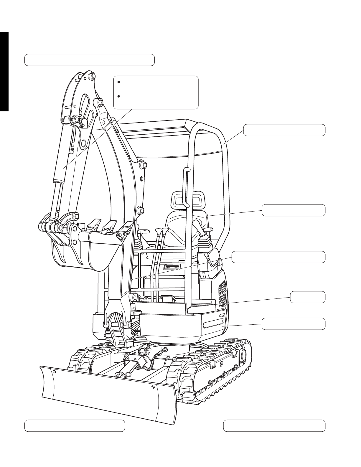
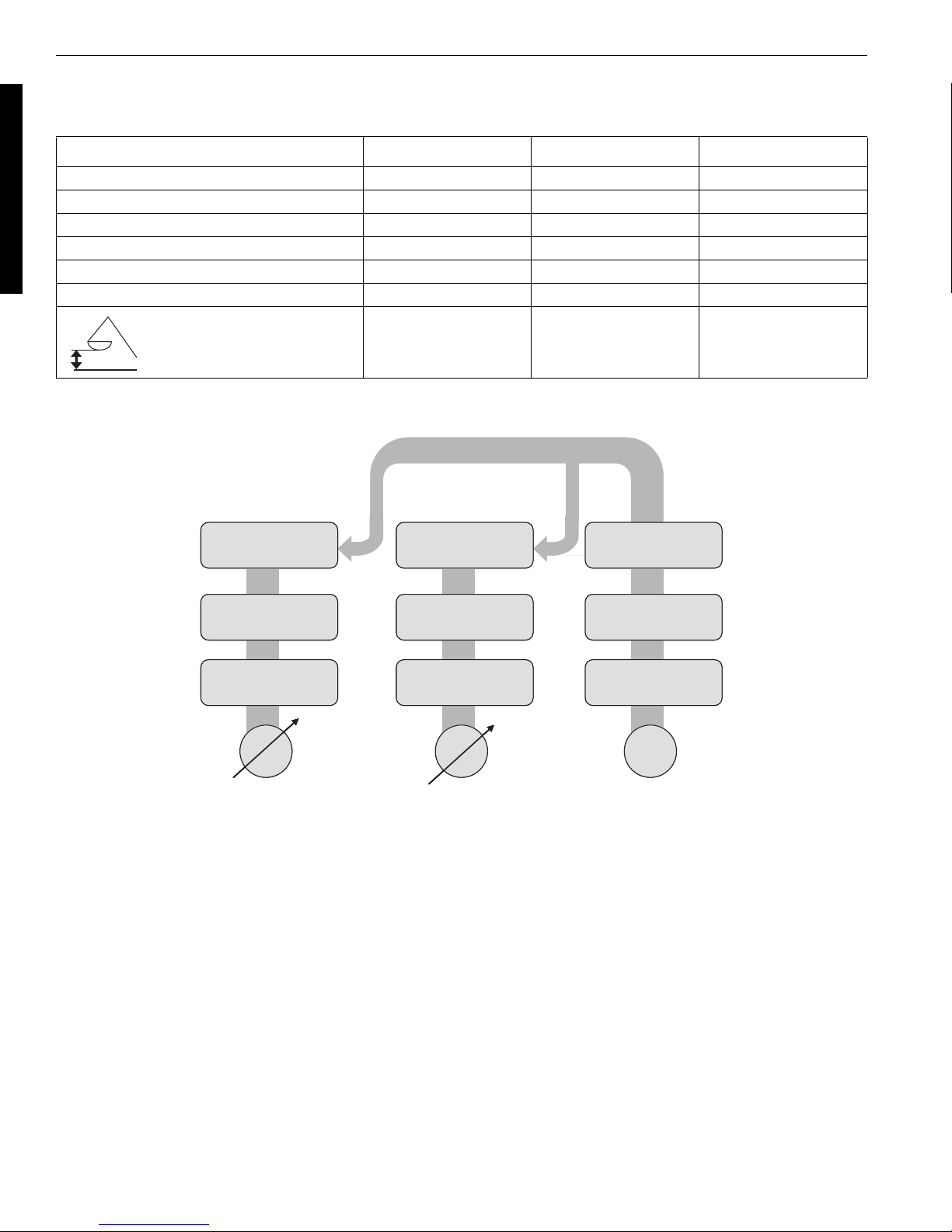
c. Major Selling Points and Improvements
1. Quick chart
Inner package of hoses for all attachments
Max. excavation capacity
increased by 22%
Max. excavation depth
increased by 10%
4-port ROPS specification
Engine start control
High-positioned boom cylinder
Flat steps
Travel lock function
Theft-proof version (EU - option)
Standard equipped with SC valve
I-4
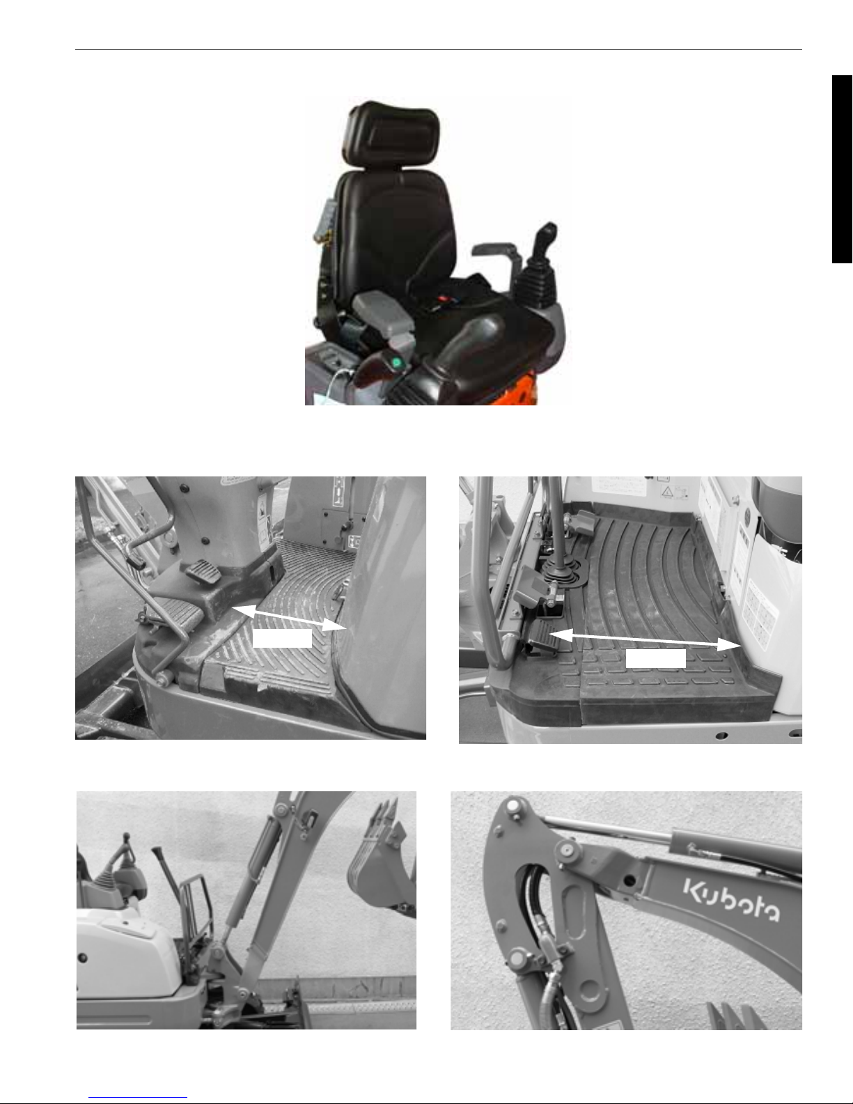
2. Wrist arm control lever
s
3. Enlarged foot space
U-15 (Previous model)
WSM U15-3
U15-3 (New model)
330mm
4. Upper positioned boom cylinder 5.
460mm
Inner package of hoses for front attachment
I-5
WSM U15-3
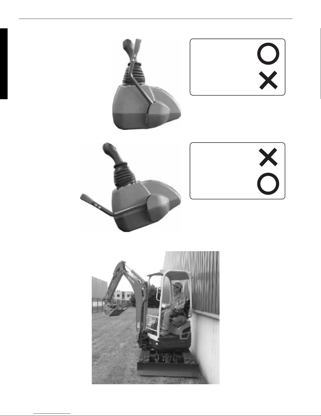
6. Engine start control, Travel lock function
Unloading lever : UP
Unloading lever : DOWN
Engine start :
Front attachment,
traveling :
Engine start :
7. 4-post ROPS
Front attachment,
traveling :
The equipment is of European specifications.
I-6
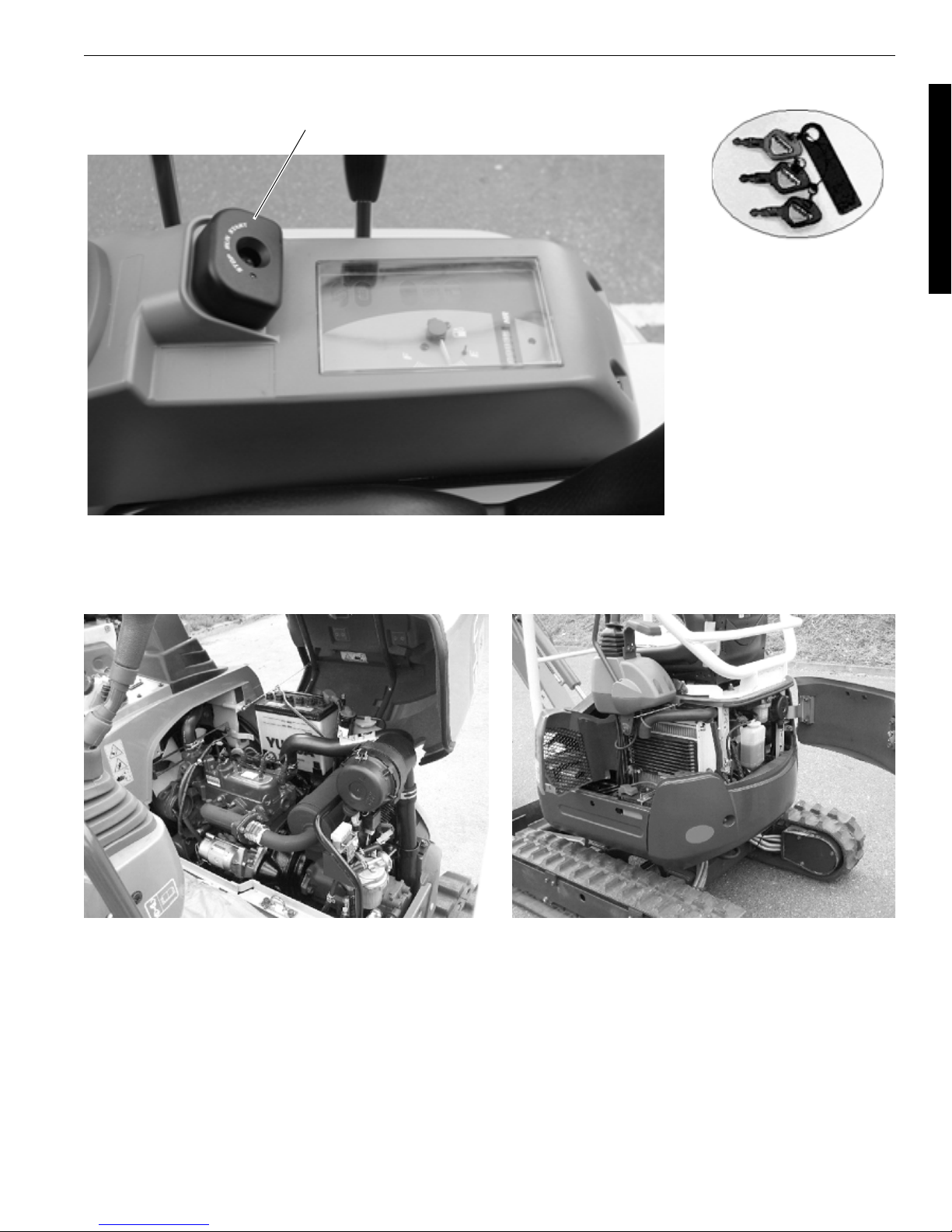
8. Machine equipped with theft-proof device (Future EU option)
Antenna unit
WSM U15-3
Starter key set
9. Side-opening type full-open hood
U-15 (Previous model) U15-3 (New model)
Paint color and equipment are of European specifications.
I-7

WSM U15-3
{
{
{
{
{
{
{
{
{
d. Evaluation of Competitive Power with Competitors
1. Workability
Offence Defense
{ Increase in engine output 9.6 8.8 11.2 8.5 11.3
{
{
{
{
{
{
{
2. Durability
Offence Defense
{
{
{
{
{
{
{
{ Boom cast steel members
{ High-tensile brass bush
Item U15-3
Max. excavation capacity
increased by 22%
Max. excavation depth
increased by 10%
Max. vertical depth
increased by 11%
Max. excavation radius
increased by 5%
Travel 2-speed traction force
increased by 5%
Travel 2-speed speed
increased by 8%
Swiveling force increased by
12%
Item U15-3
Boom cylinder Protection of
cylinder by high-positioning
Protection by inner package
of hoses for all attachments
Standard equipped with tension spring
Double-grouser type iron
crawler <For domestic market only>
Introduction of high-back
and integrated seat
Prevention of water entry by
enclosed hydraulic oil tank
Equipped with starter automatic release function
Current
U-15
15.2 12.5 14.2 13.7 14.4
2310 2100 2155 2100 2170
1900 1720 1870 1750 1720
3900 3720 3900 3720 3800
2.2/4.3 2.0/4.0 2.3/4.3 2.1/4.3 2.3/4.0
Current
U-15
KOMATSU
PC15MR
----
----
KOMATSU
PC15MR
xxxx
''xx
x {{{
x--{
x {{{
x---
x---
x { xx
x { --
YAN MAR
Vio15
YAN MAR
Vio15
SCM
301.5CR
SCM
301.5CR
Appealing point in sales
We will appeal such a
point that the max. excavation capacity and max.
excavation depth which
are the basic performances of excavating
machine take a lead over
those of our existing
machines as well as
competitive companies'
machines.
Appealing point in sales
As the greatest differentiation from competitive
companies' products, we
will appeal such a point
that loading work can be
performed without hassle. This is because the
machine can be brought
close to a 2-ton dump
truck without damage to
the boom cylinder during
loading work. Such job is
found often with
machines of this class.
We will also appeal such
a point that the machine
is equipped with the
inner package of hoses
for all attachments which
gives no damage to cylinder.
I-8

3. Operability
{
{
{
{
{
{
{
{
{
{
{
{
{
{
WSM U15-3
Offence Defense
{ Horizontal operation
Starter key used also for
{
higher-ranked models
Equipped with auto-glow
{
indicator
Right and left pedaling for
{
swing
4. Comfort
Offence Defense
{ Ample getting-on/off space
{ Flat steps
5. Maintainability
Item U15-3
Item U15-3
Current
U-15
Current
U-15
Front
operation
KOMATSU
PC15MR
x {{{We will appeal the com-
x---
x---
x {{{
KOMATSU
PC15MR
x {{{
YAN MAR
Vio15
YAN MAR
Vio15
'''
SCM
301.5CR
SCM
301.5CR
Appealing point in sales
fort and operability of
horizontal operation to
users of current U-15.
We will also appeal to
rental users that the
starter key can be used
also for higher-ranked
models.
Appealing point in sales
We will appeal the
ampleness of getting-on/
off space.
Offence Defense
{ Theft-proof specification
{
Standard equipped with SC
valve
{ Rotary joint O-ring
{ Side-opening full-open hood
{ Split-type dozer hose
Item U15-3
6. Safety
Offence Defense
{ Travel lock function, Unlock
{ Engine start control
{ Compatible with ROPS
Item U15-3
Current
U-15
Current
U-15
KOMATSU
PC15MR
x x x x We will appeal to rental
' --
x---
xxxx
{ x { x
KOMATSU
PC15MR
xxx{ We will appeal such a
xxx{
xxxx
YAN MAR
Vio15
YAN MAR
Vio15
SCM
301.5CR
SCM
301.5CR
Appealing point in sales
uses that the machine
can be equipped with a
new system theft-proof
device as well as the
improved operability of
SC valve and 4P multivalve.
Appealing point in sales
point that the machine
assures the Japan's topclass safety.
I-9
WSM U15-3
7. Working Range
U15-3 U-15 Difference
Max. excavation depth 2310 2100 +210
Max. vertical excavation depth 1900 1720 +180
Max. excavation radius 3900 3720 +180
Max. excavation height 3540 3740 -200
Max. dumping height 2440 2600 -160
Max. floor excavation radius 3840 3610 +230
1200 1270 -70
8. Outline of Hydraulic System (Travel straight function)
mm
䉰䊷䊎䉴
䊑䊷䊛
Boom
Bucket
䊋䉬䉾䊃
Travel Left
ⴕᏀ
䌐
䋱
P
1
21.6 MPa
16.6 L/min
Travel straight function is possible only together with boom operation.
Service
䉝䊷䊛
Arm
ⴕฝ
Travel Right
䌐
䋲
P
2
21.6 MPa
16.6 L/min
ᣓ࿁
Swivel
䊄䊷䉱
Dozer
䉴䉟䊮䉫
Swing
䌐
䋳
P
3
18.6 MPa
10.4 L/min
I-10
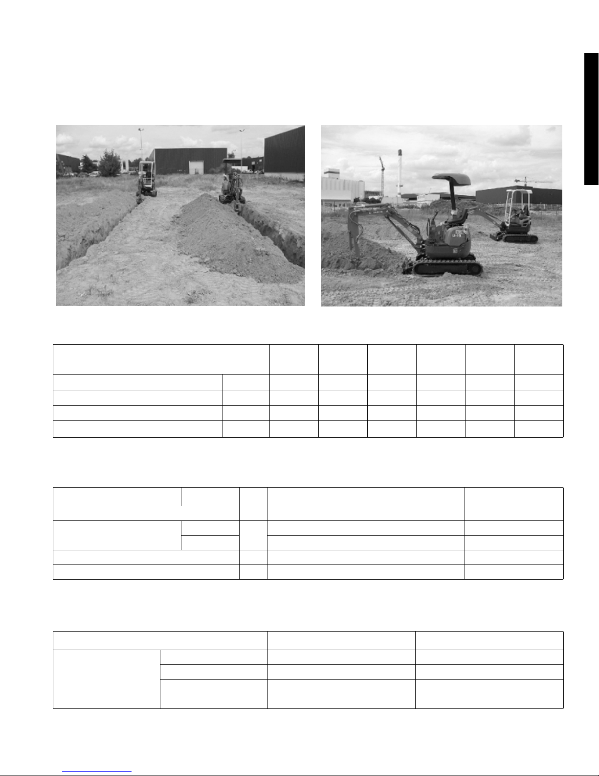
e. Actual performance comparison
1. On-site Excavation Test
-Test Conditions1 m trench excavation, 45-deg. discharge of soil
Excavation work for 10 min., (5-min. rotation)
WSM U15-3
The equipment is of European specifications.
U15-3 U-15
Volume of soil discharged per hour
Cycle time sec 8.3 9.8 +15%
Fuel consumption cc/10min 400 390
Volume of soil discharged per liter of fuel
3
/h
m
3
/L
m
31.4 25.0 +26% *24.3 *26.3 *25.9
13.1 10.7 +22%
Increasin
g rate
PC15MR-1
Vio15-2 301.5CR
* Actual measurement
2. Comparison of Operating Speed
U15-3 U-15 difference
1. Attachment operated 3 times sec 47.3 48.9 +3.4%
2. Boom
(Ground level to top)
3. Swiveling speed rpm 9.0 7.8 +13.3%
4. Combined operation sec 29.7 29.9 -0.20
UP
DOWN 2.5 2.4 -4.0%
sec
2.3 2.9 +26.1%
* Actual measurement
3. Comparison of Stability
Dynamic Front *148 *148
Tipping load
Dynamic Side *138 *127
Static Front *194 *213
Static Side *181 *177
U15-3 U-15
* Actual measurement
I-11

WSM U15-3
B.
Machine specifications
a. Major dimensions and working range (with rubber crawler)
Unit U15-3 Remarks
1 Overall length (at transport) mm 3570
2 Overall height (at transport) mm 2250
3 Overall width mm 1240/990
4 Minimum road clearance mm 145
5 Dozer outer width x height mm 1240/990 x 261
6 Tumbler-to-tumbler distance mm 1230
7 Crawler center distance mm 1010/760
8 Crawler shoe width mm 230
9 Crawler height mm 360
10 Swivel structure rear end height mm 422
11 Overall crawler length mm 1587
12 Approach angle deg. 30.1
13 Maximum digging height mm 3540
14 Maximum digging radius mm 3900
15 Maximum digging depth mm 2310
16 Maximum dumping height mm 2440
17 Maximum vertical digging depth mm 1910
18 Minimum front turning radius mm 1430/1207 Front/swing
19 Minimum tail turning radius mm 620
20 Ground contact pressure
21 Swing angle left/right deg. 63/58
22 Bucket lift angle deg. 180
23 Maximum ground digging radius mm 3840
24 Minimum ground finishing radius mm 1320
25 Radius at maximum digging height mm 2015
26 Radius at maximum dumping height mm 2012
Maximum bucket bottom height with
27
arm vertical
Overall height with arm crowded and
28
minimum front swivel radius
kPa
2
(kgf/cm
)
mm 1200 Arm vertical or fully crowded
mm 1430
25 (0.25)
from operator’s manual
I-12
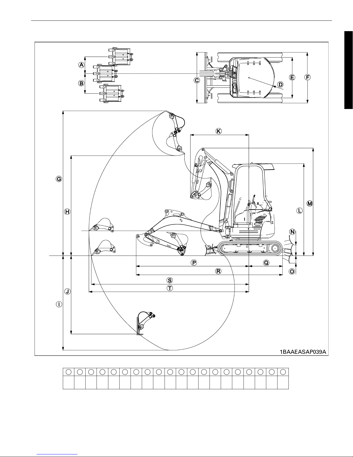
b. Dimensional drawings
WSM U15-3
A B C D E F G H I J K L M N O P Q R S T
410 485
990
1240
620
980
990
3540 2440 2310 1910 1430 2250 2630 265 180 2750 825 3570 3840 3900
1240
I-13
from operator’s manual
(mm)

WSM U15-3
c. Performance and lifting capacity
1. Performance
Unit U15-3 Remarks
Standard bucket capacity
Maximum digging force, arm KN(kgf) 8.8 (900) Teeth bottom
Maximum digging force, bucket KN(kgf) 15.2 (1550) Teeth bottom
Cycle time sec/cycle 10.8
Digging performance
Dozer capacity
heaped
Digging performance, cycle time conditions:Dig 1m depth with Standard bucket and dump soil on the
3
m
3
/h
m
3
m
ground after 45° swivel.
0.04 CECE
33.4
0.067 without extention blade
I-14
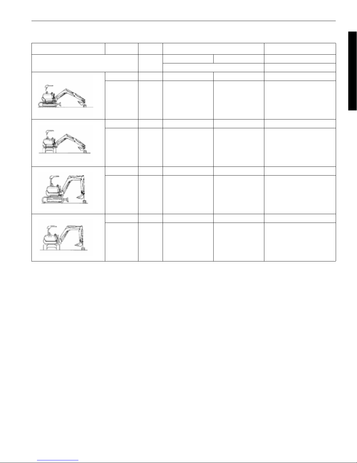
2. Lifting capacity
Lifting posture Dozer Unit U15-3 Remarks
Maximum lifting capacity
(standard arm)
(kgf)
Up kgf 215 (T) 215 (T)
Down kgf 280 (R) 280 (R)
Up kgf 100 (T) 185 (T)
Down kgf 135 (T) 195 (T)
Up kgf 475 (R) 475 (R)
Crawler extended crawler retracted
60
WSM U15-3
Down kgf 475 (R) 475 (R)
Up kgf 275 (T) 475 (R)
Down kgf 315 (T) 475 (R)
Lifting capacity
The machine can lift the loads listed above when the hydraulic pressure is as specified. But the actual measurements are based on "n = 1", which means some fluctuations are expected.
Measuring conditions:
(1) Hydraulic oil temperature: 50 ± 5 °C, riding operator (about 60 kg), engine at maximum rpm.
(2) The boom is inched until the other end of the machine comes off the ground or the boom circuit gets
relieved. Then the loads are measured.
Note:The loads also vary depending on the ground surface condition, dozer's ground-contact status,
operator's weight, remaining fuel and other factors.
(3) The boom swing position is set at the center.
(The machine may turn over if it is set off the center.)
*The above figures show the machine that is about to life a load.
In the above table, (T) means that the machine may turn over if the load is heavier. And (R) means that the
boom circuit gets relieved if the load is heavier.
I-15

WSM U15-3
I-16

WSM U15-3
II Service engineering section
A.Maintenance specifications. . . . . . . . . . . . . . . . . . . . . . . . . II-3
a. List of oil and water quantities. . . . . . . . . . . . . . . . . . . . . . . . . . . . . . II-3
b. Tightening torque . . . . . . . . . . . . . . . . . . . . . . . . . . . . . . . . . . . . . . . II-4
c. Quality specifications . . . . . . . . . . . . . . . . . . . . . . . . . . . . . . . . . . . . II-6
d. Operating noise. . . . . . . . . . . . . . . . . . . . . . . . . . . . . . . . . . . . . . . . II-11
B.Machine body structure and function . . . . . . . . . . . . . . . . II-13
a. Overall Arrangement . . . . . . . . . . . . . . . . . . . . . . . . . . . . . . . . . . . . II-13
b. Front attachment. . . . . . . . . . . . . . . . . . . . . . . . . . . . . . . . . . . . . . . II-23
c. Control levers and linkage. . . . . . . . . . . . . . . . . . . . . . . . . . . . . . . . II-28
d. Under carriage components . . . . . . . . . . . . . . . . . . . . . . . . . . . . . . II-34
C.Engine. . . . . . . . . . . . . . . . . . . . . . . . . . . . . . . . . . . . . . . . II-44
a. Main specification . . . . . . . . . . . . . . . . . . . . . . . . . . . . . . . . . . . . . . II-44
b. Performance curves . . . . . . . . . . . . . . . . . . . . . . . . . . . . . . . . . . . . II-45
c. Engine electrical data . . . . . . . . . . . . . . . . . . . . . . . . . . . . . . . . . . . II-46
d. Engine servicing data . . . . . . . . . . . . . . . . . . . . . . . . . . . . . . . . . . . II-47
e. Engine Mount . . . . . . . . . . . . . . . . . . . . . . . . . . . . . . . . . . . . . . . . . II-48
f. Fuel System . . . . . . . . . . . . . . . . . . . . . . . . . . . . . . . . . . . . . . . . . . II-49
g. Cooling system . . . . . . . . . . . . . . . . . . . . . . . . . . . . . . . . . . . . . . . . II-52
h. Air cleaner. . . . . . . . . . . . . . . . . . . . . . . . . . . . . . . . . . . . . . . . . . . . II-54
D.Hydraulic system. . . . . . . . . . . . . . . . . . . . . . . . . . . . . . . . II-55
a. Main pump . . . . . . . . . . . . . . . . . . . . . . . . . . . . . . . . . . . . . . . . . . . II-55
b. Control valve . . . . . . . . . . . . . . . . . . . . . . . . . . . . . . . . . . . . . . . . . . II-61
c. Swivel motor . . . . . . . . . . . . . . . . . . . . . . . . . . . . . . . . . . . . . . . . . . II-69
d. Travel motor (Wheel motor) . . . . . . . . . . . . . . . . . . . . . . . . . . . . . . II-73
e. Pilot valve (Remote control valve). . . . . . . . . . . . . . . . . . . . . . . . . . II-83
f. Cylinders . . . . . . . . . . . . . . . . . . . . . . . . . . . . . . . . . . . . . . . . . . . . . II-87
g. Swivel Joint (Rotary joint) . . . . . . . . . . . . . . . . . . . . . . . . . . . . . . . . II-92
h. Unload valve . . . . . . . . . . . . . . . . . . . . . . . . . . . . . . . . . . . . . . . . . . II-96
i. Selector valve . . . . . . . . . . . . . . . . . . . . . . . . . . . . . . . . . . . . . . . . . II-98
j. Accessaries of hydraulic compornents . . . . . . . . . . . . . . . . . . . . . . II-99
h. Hydraulic system flow . . . . . . . . . . . . . . . . . . . . . . . . . . . . . . . . . . II-103
l. Service port system. . . . . . . . . . . . . . . . . . . . . . . . . . . . . . . . . . . . II-108
m. Hydraulic components layout : U15-3 . . . . . . . . . . . . . . . . . . . . . . II-111
n. Hydraulic circuit diagram. . . . . . . . . . . . . . . . . . . . . . . . . . . . . . . . II-112
II-1

WSM U15-3
E.Electrical system. . . . . . . . . . . . . . . . . . . . . . . . . . . . . . . II-113
a. New Functions of Electric System . . . . . . . . . . . . . . . . . . . . . . . . . II-113
b. Battery circuit . . . . . . . . . . . . . . . . . . . . . . . . . . . . . . . . . . . . . . . . . II-114
c. Key switch (Engine starter switch). . . . . . . . . . . . . . . . . . . . . . . . . II-115
d. Safty lever lock switch . . . . . . . . . . . . . . . . . . . . . . . . . . . . . . . . . . II-116
e. Solenoid valve . . . . . . . . . . . . . . . . . . . . . . . . . . . . . . . . . . . . . . . . II-118
f. Travel hi-speed control circuit . . . . . . . . . . . . . . . . . . . . . . . . . . . . II-120
g. Meter panel . . . . . . . . . . . . . . . . . . . . . . . . . . . . . . . . . . . . . . . . . . II-127
h. Fuses . . . . . . . . . . . . . . . . . . . . . . . . . . . . . . . . . . . . . . . . . . . . . . . II-133
i. Auto glow circuit. . . . . . . . . . . . . . . . . . . . . . . . . . . . . . . . . . . . . . . II-134
j. Auto release control system . . . . . . . . . . . . . . . . . . . . . . . . . . . . . II-144
k. Water temp. sensor & gauge . . . . . . . . . . . . . . . . . . . . . . . . . . . . . II-151
l. Fuel control circuit . . . . . . . . . . . . . . . . . . . . . . . . . . . . . . . . . . . . . II-153
m. Engine stop solenoid . . . . . . . . . . . . . . . . . . . . . . . . . . . . . . . . . . . II-154
n. coil commander . . . . . . . . . . . . . . . . . . . . . . . . . . . . . . . . . . . . . . . II-156
o. Fuel sensor . . . . . . . . . . . . . . . . . . . . . . . . . . . . . . . . . . . . . . . . . . II-158
p. Engine oil pressure sensor circuit . . . . . . . . . . . . . . . . . . . . . . . . . II-161
q. Engine electrical system . . . . . . . . . . . . . . . . . . . . . . . . . . . . . . . . II-162
r. Horn circuit. . . . . . . . . . . . . . . . . . . . . . . . . . . . . . . . . . . . . . . . . . . II-164
s. Charging system (Alternator). . . . . . . . . . . . . . . . . . . . . . . . . . . . . II-167
t. Relay . . . . . . . . . . . . . . . . . . . . . . . . . . . . . . . . . . . . . . . . . . . . . . . II-171
u. Route of Electric Wiring . . . . . . . . . . . . . . . . . . . . . . . . . . . . . . . . . II-174
v. Electrical component layout. . . . . . . . . . . . . . . . . . . . . . . . . . . . . . II-181
w. Electric Circuit . . . . . . . . . . . . . . . . . . . . . . . . . . . . . . . . . . . . . . . . II-182
x. Electrical Wiring diagram . . . . . . . . . . . . . . . . . . . . . . . . . . . . . . . . II-187
II-2

A.Maintenance specifications
a. List of oil and water quantities
Unit U15-3 Remarks
Radiator soft water L 2.7 Kubota LLC-N-50F
Reserve tank soft water L 0.6
Crankcase engine oil
(at filter replacement)
Hydraulic tank oil L 13 ISO 46
Total hydraulic oil L 22 ISO 46
Wheel motor gear oil L 0.25 SAE 90 (API, GL-4)
Swivel reducer gear oil L -
Track roller gear oil cc 40 Engine Oil SAE 30 Class CD
Carrier roller
(upper track roller)
Front idler cc 30 Engine Oil SAE 30 Class CD
Fuel tank light oil (full) L 18 Diesel light oil No. 3
L3.5
cc - Grease EP2
Class CC
10W30
WSM U15-3
II-3

WSM U15-3
b. Tightening torque
1. Machine
Loctite U15-3 Remarks
Travel wheel motor { 60.8 ~ 70.6 (6.2 ~ 7.2)
Control valve {
Sprocket { 60.8 ~ 70.6 (6.2 ~ 7.2)
Track roller { 103 ~ 117.7 (10.5 ~ 12)
Carrier roller 48.1 ~ 55.9 (4.9 ~ 5.7) Slide plate
Plate (idler) 77.5 ~ 90.2 (7.9 ~ 9.2)
Grease cylinder nipple 98.0 ~ 108.0 (9.0 ~ 11.0)
Swivel bearing { 103 ~ 117.7 (10.5 ~ 12)
Swivel motor { 367.7 ~ 431.5 (37.5 ~ 44.0)
Return filter 19.6 ~ 29.4 (2.0 ~ 3.0)
Engine bracket/engine support {
Engine anti-vibration rubber { 39.2 ~ 45.1 (4.0 ~ 4.6) Nut
Engine anti-vibration rubber 39.2 ~ 45.1 (4.0 ~ 4.6)
Counterweight { 107.9 ~ 125.5 (11.0 ~ 12.8) Oil tank
Coupling 48.1 ~ 55.9 (4.9 ~ 5.7)
Main pump 77.5 ~ 90.2 (7.9 ~ 9.2)
Rotary joint 48.1 ~ 55.9 (4.9 ~ 5.7)
Rotary joint stopper { 48.1 ~ 55.9 (4.9 ~ 5.7)
Muffler flange 23.5 ~ 27.5 (2.4 ~ 2.8)
Control valve through bolt 13.7 ~ 14.7 (1.4 ~ 1.5)
Unit: N·m (kgf·m)
2. General bolt/nut tightening torque
Unit: N·m (kgf·m)
4T 7T 9T
M6 7.8 ~ 9.3 (0.8 ~ 0.95) 9.8 ~ 11.3 (1.0 ~ 1.15) 12.3 ~ 14.2 (1.25 ~ 1.45)
M8 17.7 ~ 20.6 (1.8 ~ 2.1) 23.5 ~ 27.5 (2.4 ~ 2.8) 29.4 ~ 34.3 (3.0 ~ 3.5)
M10 39.2 ~ 45.1 (4.0 ~ 4.6) 48.1 ~ 55.9 (4.9 ~ 5.7) 60.8 ~ 70.6 (6.2 ~ 7.2)
M12 62.8 ~ 72.6 (6.4 ~ 7.4) 77.5 ~ 90.2 (7.9 ~ 9.2) 103.0 ~ 117.7 (10.5 ~ 12.0)
M14 107.9 ~ 125.5 (11.0 ~ 12.8) 123.6 ~ 147.1 (12.6 ~ 15.0) 166.7 ~ 196.1 (17.0 ~ 20.0)
M16 166.7 ~ 191.2 (17.0 ~ 19.5) 196.1 ~ 225.4 (20.0 ~ 23.0) 259.7 ~ 304 (26.5 ~ 31.0)
M18 245.2 ~ 284.4 (25.0 ~ 29.0) 274.6 ~ 318.7 (28.0 ~ 32.5) 343.2 ~ 402.1 (35.0 ~ 41.0)
M20 333.4 ~ 392.3 (34.0 ~ 40.0) 367.7 ~ 431.5 (37.5 ~ 44.0) 519.8 ~ 568.8 (53.0 ~ 58.0)
II-4
3. Hydraulic pipe tightening torque
WSM U15-3
Steel pipe size (mm)
(O.D. x I.D. x Thickness)
I8 x 6 x t1
I10 x 7 x t1.5
I12 x 9 x t1.5
I16 x 12 x t2
I18 x 14 x t2
I27.2 x 21.6 x t2.8
Tightening torque
N·m (kgf·m)
29.4 ~ 39.2 (3.0 ~ 4.0) *17
39.2 ~ 44.1 (4.0 ~ 4.5) *19
53.9 ~ 63.7 (5.5 ~ 6.5) *21
88.3 ~ 98.1 (9.0 ~ 10.0) *29
127.5 ~ 137.3(13.0 ~ 14.0) *32
235.4 ~ 255.0(24.0 ~ 26.0) *41
Wrench width (mm)
[Reference]
Remarks
* Ihara-made sleeve nuts
4. Hydraulic hose tightening torque
Thread size
(piping thread)
1/8” 7.8 ~ 11.8 (0.8 ~ 1.2) 19.6 ~ 29.4 (2.0 ~ 3.0) *17
1/4” 24.5 ~ 29.4 (2.5 ~ 3.0) 36.3 ~ 44.1 (3.7 ~ 4.5) *19
3/8” 37.2 ~ 42.1 (3.8 ~ 4.3) 68.6 ~ 73.5 (7.0 ~ 7.5) *22
1/2” 58.8 ~ 63.7 (6.0 ~ 6.5) 83.4 ~ 88.3 (8.5 ~ 9.0) *27
3/4” 117.7 ~ 127.5 (12.0 ~ 13.0) 166.6 ~ 181.3 (17.0 ~ 18.5) *36
Note: * Wrench width may vary depending on the manufacturer, thread diameter and other factors.
Tightening torque N·m (kgf·m)
Union nut Taper thread
Wrench width
[Reference]
Remarks
5. Engine
N·m (kgf·m)
Engine model D782
Cylinder head cover 4.9 (0.5)
Nozzle holder 58.8 (6.0)
Rocker arm bracket nut 10.8 (1.1)
Cylinder head cover 40.2 (4.1)
Connecting rod bolt 28.4 (2.9)
Flywheel 56.9 (5.8)
Bg case bolt 1 14.7 (1.5)
Bg case bolt 2 28.4 (2.9)
Bearing case cover bolt 10.8 (1.1)
Hose clamp (threaded type) N·m (kgf·cm)
Part code Applicable diameter (mm) Tightening torque
09318-89016 12 ~ 16 2.5 ~ 3.4 (25 ~ 35)
09318-89039 31 ~ 40 2.5 ~ 3.4 (25 ~ 35)
09318-89045 36 ~ 46 2.5 ~ 3.4 (25 ~ 35)
RB101-63631 13 ~ 20 3.4 ~ 4.4 (35 ~ 45)
RC101-64581 15 ~ 25 4.9 ~ 5.9 (50 ~ 60)
68311-72821 26 ~ 38 4.9 ~ 5.9 (50 ~ 60)
RC411-63181 40 ~ 55 4.9 ~ 5.9 (50 ~ 60)
RC401-63191 50 ~ 60 4.9 ~ 5.9 (50 ~ 60)
69284-63171 77 ~ 95 4.9 ~ 5.9 (50 ~ 60)
RD411-63821 32 ~ 44 4.9 ~ 5.9 (50 ~ 60)
II-5
WSM U15-3
c. Quality specifications
No Specificatios Items Unit U15-3 Remarks
Q1 Main Speed JIS A8404
1 1 Machine size Total length (Transport) mm 3575 ± 71
2 Total width mm 1240/990 ± 12
3 Total height (Canopy) mm 2300 ± 23
4 Total height (Cabin) mm -
2 1 Weight Machine weight (Canopy) kg 1600 ± 32 Fuel tank
2 Machine weight (Cabin) kg -
3 1 Performance Swivel speed rpm 8.7 ± 0.9 Rated engine RPM, K=100%
2 Travel speed F1 km/h 2.2 ± 0.2
3F2km/h4.0 ± 0.4
4 R1 km/h 2.2 ± 0.2
5 R2 km/h 4.0 ± 0.4
6 Gradeability deg 30 <
4 1 Rear end min. turning radius mm 620 ± 12
2 Swivel frame rear ground clearance mm 422 ± 8
3 Tambler center distance mm 1230 ± 37
4 Crawler total length mm 1587 ± 48
5 Crawler total width mm 1240/990 ± 26
6 Crawler shoe width mm 230 ± 5
7 Min. ground clearance mm 145 ± 4
5 1 Engine, Model name D782-BH-4
2 Rated output DIN 70020 kw 9.6 ± 0.2
ps 13.0 ± 0.3
3 Rated speed rpm 2300
4 Displacement L 0.778
cc 778
6 1 Hydraulic pump type Variable x2 +gear
2 Pump delivery L 16.6 x 2, 10.4, 6.2
3 Main relief pressure
(Bench set)
P1,P2 Mpa
kgf/cm
2
Bar
P3 Mpa
2
kgf/cm
Bar
P4 Mpa
2
kgf/cm
Bar
7 1 Swivel motor type
8 1 Under carrage Travel motor type Variable displace-
3 Crawler shoe type Rubber
+1.0
21.6
-
0.5
+10
220
-
5
+9.8
216
-
4.9
+1.0
18.6
-
0.5
+10
190
-
5
+9.8
186
-
4.9
+1.0
3.9
-
0.5
+10
40
-
5
+9.8
39
-
4.9
ment pump
II-6
WSM U15-3
No Specificatios Items Unit U15-3 Remarks
9 1 Front attachment Bucket
2
heaped
capacity
CECE
3 Bucket width mm 456 ± 10 Without side cutter
4 Swing angle L deg 63 ± 2
5 R deg 58 ± 2
6 Max. digging radius mm 3901 ± 59
7
Ground level Max. digging radius
8 Ground level Min. finish radius mm 1320 ± 26 Bucket bottom horizontal
9 Max. digging depth mm 2306 ± 46
10 Max. vertical digging depth mm 1911 ± 38
11 Max. digging height mm 3536 ± 71
12 Max. dump height mm 2443 ± 49
14 Mini. turning radius mm 1426 ± 43
15 Mini. turning radius
(Left swing)
16 Off-set
17 R mm 385 ± 12
amount
Lmm510 ± 15
18 Max. digging force kgf 1.55
10 1 Dozer Width mm 1244/990 ± 5
2 Height mm 261 ± 5
4 Max. lift above GL mm 263 ± 13
5 Max. below GL mm 182 ± 9
11 4 Water & oil Fuel Tank L 17.5 ± 0.9
5 Hydraulic oil Tank L 13 ± 0.7
Q2 Main Specs JIS A8404
1 1 Bucket tooth slaggish mm 73 ± 93
2 Decline of front attachment mm 0 ± 10
3 Dozer's declination mm 0 ± 10
3 3 Min. clearance of bucket teeth to boom cylinder protector mm
4 1 Approach angle deg 30.1 ± 3.0
5 1 Crawler height mm 360 ± 7 Include grouser on the sprocket
2 Max. crawler height mm 360 ± 7
Q3 Engine performance
1 1 Max. engine torque
2 1 Max, engine rpm no load rpm 2600 >
2 1 pump relief rpm
3 2 pump relief rpm 2300 <
4 3 pump relief rpm 2300 <
3 1 Idling rpm rpm 1200 + 150/-0
3
m
0.04 ± 0.002
mm 3843 ± 58
mm 1207 ± 36
N15.2
+34
37
-
16
kgf•m/rpm
N•m/rpm
4.52/1750
44.3/1750
II-7

WSM U15-3
No Specificatios Items Unit U15-3 Remarks
Q4 Travelling performance
1 1 Travel motor block performance, L/R mm 300 > 20 deg, 10 min
2 1 Max, Traction force F1 kgf•m 1255 ± 126 K=65%
kN•m 12.8 ± 1.3
2 F2 kgf•m 637 ± 64
kN•m 6.5 ± 0.7
3 1 Travel straightness F1 mm 600 > 10m distance
2 F2 mm 600 >
3 Dozer F1 mm 600 > Dozer up & down 10m distance
4 Dozer R1 mm 600 >
4 1 Track shoe sag distance Iron mm 25 ~ 30
2 Rubber mm 10 ~ 15
Q5 Work performance
4 2 Arm digging force kgf 824< Bucket tooth root
kN 8.4<
3 Bucket digging force kgf 1412< Machine stance to JIS bucket tooth
kN 14.4<
5 1 Boom speed up sec 2.2 ± 0.3 Oil temp. 50 ± 5°C
3 down sec 2.5 ± 0.3 Oil temp. 50 ± 5°C
6 1 Arm speed crowd sec 3.5 ± 0.3 Oil temp. 50 ± 5°C
2 extend sec 2.4 ± 0.3 Oil temp. 50 ± 5°C
7 1 Bucket speed crowd sec 2.8 ± 0.3 Oil temp. 50 ± 5°C
2 dump sec 1.9 ± 0.3 Oil temp. 50 ± 5°C
8 1 Dozer speed up sec 1.4 ± 0.3 Max. down to max. up
2 down sec 1.9 ± 0.3 Max. up to max. down
13 1 Max. digging height radius mm 2015 ± 202
2 Max. dump height radius mm 2012 ± 121 at bucket pin
4 Bucket bottom height at arm vertical mm 1200 ± 36 Bucket horizontal
5 Bucket wrist angle degree 180 ± 3
Q6 Swivel, swing performance
1 1 Swivel torque L kgf•m 217 < Arm extend,show/Quick
kN•m 2.1 <
2Rkgf•m217 <
kN•m 2.1 <
2 1 Swivel capable angle at slope deg 18 < Bucket load=JIS heaped x 1.8
3 1 Swivel block performance L/R deg 30 >
5 1 Swivel start-up speed sec 2.1 ± 0.2 0 ~ 90 deg swivel
7 1 Swing speed Left sec 4.6 ± 0.3
2 Right sec 3.7 ± 0.3
8 1 Swing Lock Swivel R&L mm 6 > 90 deg-swivel, 100 times actual
root
Max. heiht to ground
digging cylinder dislocation
II-8

WSM U15-3
No Specificatios Items Unit U15-3 Remarks
Q7 Hydraulic performance
1 1 Relief pressure setting P1
kgf/cm
2
MPa
bar
2P2
kgf/cm
2
MPa
bar
3P3
kgf/cm
2
MPa
bar
4P4
kgf/cm
2
MPa
bar
5 1 Cylinder block performance Boom mm 25 > Arm extend, bucket
2 Arm mm 15 >
3 Bucket mm 10 >
4 Dozer mm 25 >
6 1 Boom cushioning performance 30°C sec 3 >
2 50°C sec 0.5 to 1.5
3 80°C sec 0.3 <
8 1 Service port flow No load/load L 27
Q8 Lever operating force & stroke
1 1 Boom lever operating force kgf 1.4 ± 0.5 Measured 20 mm below the grip
kN 13.7 ± 4.9
4 Arm lever kgf 1.4 ± 0.5
N 13.7 ± 4.9
5 Bucket lever kgf 1.4 ± 0.5
N 13.7 ± 4.9
6 Swivel (Swing) lever kgf 1.4 ± 0.5
N 13.7 ± 4.9
7 Dozer lever kgf 3.1 ± 0.5
N 30.0 ± 4.9
8 Travel lever L/R kgf 1.5 ± 0.5
N 15.0 ± 4.9
9 Accelerator lever (up/down) kgf 3.4 ± 1.5 Measured 30 mm below the grip
N 35.0 ± 14.7
10 Swing pedal kgf 10.0 ± 1.0 Measured Step end.
N 98.0 ± 9.8
11 Safety lock lever, L&R up kgf 2.0 ± 1.0
N 20.0 ± 9.8
down kgf 3.0 ± 1.0
N 30.0 ± 9.8
220
21.6
215.8
220
21.6
215.8
190
18.6
186.3
40
3.9
39.2
+10
-
+10
-
+1.0
-
+10
-
+1.0
-
+10
-
+1.0
-
5
+1.0
-
+9.8
-
5
5
5
0.5
0.5
+9.8
-
0.5
+9.8
-
0.5
+9.8
-
4.9
4.9
4.9
4.9
Hydraulic oil temp. 50 ± 5°C
height 1m, 10 min.
Bucket load : Heaped
Soil gravity : 1.8
end.
end.
II-9
WSM U15-3
No Specificatios Items Unit U15-3 Remarks
1 13 Service port pedal kgf 5.0 ± 1.0 L / R
N 51.0 ± 10
2 1 Boom lever stroke up mm 72 ± 10 Measured grip end
2 down mm 72 ± 10
3 Arm lever stroke (crowd/dump) mm 72 ± 10
4 Bucket lever stroke (crowd/dump) mm 74 ± 10
5 Swivel lever stroke mm 74 ± 10
6 Dozer lever up & down mm 80 ± 10
7 Travel lever, L & R, F & R L mm 75 ± 10
R mm 75 ± 10
9 Swing pedal stroke mm 6 ± 10 Measured Step end
10 Service port pedal stroke (LH & RH) mm 12 ± 10
Q9 Stability
1 1 Standard arm, Dynamic
operation load limit
2 Bucket load
3 Bucket load
2 1 Standard arm, Static
operation load limit
2 Bucket load
Q10 Comfortability
11Noise level At operator’s
2 Cab db(A) - Cab door close
3 Noise source; LWA db(A) 92 >
Bucket load
to 10 degrees
tipping
to tipping,
track frame
extended
to tipping,
track frame
retracked
Bucket load
to tipping,
track frame
extended
to tipping,
track frame
retracked
ear LPA
Side, dozer up kgf - arm extended, bucket crowd, swing
N-
Over end,
dozer up
Side, dozer up kgf 121 <
Over end,
dozer up
Side, dozer up kgf 63 <
Over end,
dozer up
Side, dozer up kgf 162 < front level crowd, swing 0 degree,
Over end,
dozer up
Side, dozer up kgf 95 <
Over end,
dozer up
Canopy db(A) 78 >
kgf -
N-
N1187 <
kgf 130 <
N1275 <
N 618 <
kgf 130 <
N1275 <
N1589 <
kgf 175 <
N1716 <
N932 <
kgf 175 <
N1716 <
0 degree, exclude bucket weight
37Kg.
exclude bucket weight 37Kg.
Load is added at the top of arm.
II-10
 Loading...