

Page 1

Code No. K1042-7121-4
OPERATOR'S MANUAL
©
KUBOTA Corporation 2008
PRINTED IN U.S.A.
READ AND SAVE THIS MANUAL
T2080
T2380
T1880MODELS
T
1
8
8
0
·
T
2
0
8
0
·
T
2
3
8
0
1BDADAFAP0010
Page 2
KUBOTA Corporation is ···
Since its inception in 1890, KUBOTA Corporation has grown to
rank as one of the major firms in Japan.
To achieve this status, the company has through the years
diversified the range of its products and services to a remarkable
extent. Nineteen plants and 16,000 employees produce over 1,000
different items, large and small.
All these products and all the services which accompany them,
however, are unified by one central commitment. KUBOTA makes
products which, taken on a national scale, are basic necessities.
Products which are indispensable. Products which are intended to
help individuals and nations fulfill the potential inherent in their
environment. KUBOTA is the Basic Necessities Giant.
This potential includes water supply, food from the soil and from
the sea, industrial development, architecture and construction,
transportation.
Thousands of people depend on KUBOTA's know-how, technology,
experience and customer service. You too can depend on
KUBOTA.
Abbreviations Definitions
ABBREVIATION LIST
American Petroleum Institute
Power Take Off
Permanent Type (=Ethylene glycol anti-freeze)
Revolutions Per Minute
Society of Automotive Engineers
Kubota Reverse Awareness System
API
PTO
PT
rpm
SAE
KRA
UNIVERSAL SYMBOLS
As a guide to the operation of your machine, various universal symbols have been utilized on the instruments and
controls. The symbols are shown below with an indication of their meaning.
Safety Alert Symbol
Gasoline Fuel
Brake
Parking Brake
Engine-Stop
Engine-Run
Starter Control
Power Take-Off Clutch Control-Off Position
Power Take-Off Clutch Control-On Position
Mower-Lowered position
Mower-Raised position
Cutting Height
Headlight
Headlight-ON
Headlight-OFF
Fast
Slow
Engine Speed Control
Choke
Battery
Oil Pressure
Cruise Control
California Proposition 65
3 WARNING 3
This spark ignition system complies with Canadian ICES-002.
The engine exhaust from this product
contains chemicals known to the State
of California to cause cancer, birth
defects or other reproductive harm.
Page 3

FOREWORD
3
SAFETY FIRST
IMPORTANT :
NOTE :
3
DANGER :
3
WARNING :
3
CAUTION :
Indicates an imminently hazardous situation which, if not
avoided, will result in death or serious injury.
Indicates a potentially hazardous situation which, if not
avoided, could result in death or serious injury.
Indicates a potentially hazardous situation which, if not
avoided, may result in minor or moderate injury.
Indicates that equipment or property damage could result if
instructions are not followed.
Gives helpful information.
You are now the proud owner of a KUBOTA LAWN TRACTOR. This machine is a
product of KUBOTA's quality engineering and manufacturing. It is made of fine
materials and under a rigid quality control system. It will give you long, satisfactory
service. To obtain the best use of your machine, please read this manual carefully.
It will help you become familiar with the operation of the machine and contains
many helpful hints about machine maintenance. It is KUBOTA's policy to utilize, as
quickly as possible, every advance in our research. The immediate use of new
techniques in the manufacturing of products may cause some small parts of this
manual to be outdated. KUBOTA distributors and dealers will have the most
up-to-date information. Please do not hesitate to consult them.
This symbol, the industry's ''Safety Alert Symbol'', is used throughout this manual
and on labels on the machine itself to warn of the possibility of personal injury.
Read these instructions carefully. It is essential that you read the instructions and
safety regulations before you attempt to assemble or use this unit.
Page 4

CONTENTS
SAFE OPERATION ................................................................................................. 1
SERVICING OF MACHINE ......................................................................................... 1
SPECIFICATIONS....................................................................................................... 2
INSTRUMENT PANEL AND CONTROLS................................................................... 4
MOWER MOUNTING .................................................................................................. 5
ATTACHING THE MOWER ..................................................................................... 5
ADJUSTING THE MOWER DECK (FOR BEAUTIFUL FINISH CUT) ..................... 7
OPERATING THE ENGINE....................................................................................... 10
STARTING THE ENGINE ...................................................................................... 10
Parking Brake Lock Pedal ..............................................................................................10
Throttle Lever & Choke Knob .........................................................................................11
Key Switch......................................................................................................................11
COLD WEATHER STARTING ............................................................................... 12
CHECKING SAFETY DEVICES ............................................................................ 12
CHECK WHILE OPERATING THE ENGINE ......................................................... 13
STOPPING THE ENGINE...................................................................................... 13
WARMING UP ....................................................................................................... 14
Warm-up and Transmission Oil in the Low Temperature Range....................................14
JUMP STARTING .................................................................................................. 15
OPERATING THE MACHINE.................................................................................... 16
OPERATING NEW MACHINE ............................................................................... 16
Changing Lubricating Oil for New Machines...................................................................16
STARTING ............................................................................................................. 17
Seat ................................................................................................................................17
Light Switch ....................................................................................................................17
Lift Lever.........................................................................................................................17
Throttle Lever..................................................................................................................18
Parking Brake ................................................................................................................. 18
Speed Control Pedal....................................................................................................... 18
Cruise Control Device..................................................................................................... 19
STOPPING............................................................................................................. 20
CHECK DURING DRIVING ................................................................................... 20
Immediately Stop the Engine if:......................................................................................20
Easy Checker (TM)......................................................................................................... 20
Hourmeter (option).......................................................................................................... 20
PARKING ............................................................................................................... 21
Parking............................................................................................................................21
TRANSPORTING................................................................................................... 21
Hydrostatic Transaxle Bypass Rod.................................................................................21
OPERATING THE MOWER ...................................................................................... 22
MAKING THE MOST OF YOUR MOWER............................................................. 22
ADJUSTING CUTTING HEIGHT ........................................................................... 22
Cutting Height Control Dial .............................................................................................22
Page 5

CONTENTS
OPERATING THE MOWER................................................................................... 23
KRA system Normal Operating Mode.............................................................................23
PTO Lever ......................................................................................................................24
KRA system Override Mode ........................................................................................... 24
WHEN OPERATING MULCHING FUNCTION ...................................................... 25
TO CHANGE THE OPERATING MODE FROM MULCHING
TO SIDE DISCHARGE .......................................................................................... 27
ADJUSTING THE CLAMP ..................................................................................... 28
Side Discharge Position..................................................................................................28
Mulching Position............................................................................................................28
MAINTENANCE......................................................................................................... 29
SERVICE INTERVALS .......................................................................................... 29
LUBRICANTS AND FUEL...................................................................................... 30
Hydrostatic Transmission ...............................................................................................31
PERIODIC SERVICE................................................................................................. 32
HOW TO OPEN THE HOOD ................................................................................. 32
Hood ...............................................................................................................................32
Engine Cover..................................................................................................................32
DAILY CHECK ....................................................................................................... 32
Checking Amount of Fuel and Refueling ........................................................................33
Checking Engine Oil Level.............................................................................................. 34
Checking Cooling Air Intake Screen...............................................................................34
Oiling...............................................................................................................................35
EVERY 25 HOURS ................................................................................................ 37
Cleaning Air Cleaner.......................................................................................................37
EVERY 50 HOURS ................................................................................................ 38
Adjusting Belt Tensions and Replacement.....................................................................38
Checking Brake Pedal ....................................................................................................40
Lubricating All Grease Fittings........................................................................................ 40
Checking Tire Pressure .................................................................................................. 41
Inflation Pressure............................................................................................................41
Checking Air Cleaner Element [T2080,T2380] ............................................................... 41
EVERY 100 HOURS .............................................................................................. 42
Changing Engine Oil....................................................................................................... 42
Cleaning Engine Shroud................................................................................................. 43
Checking Spark Plug [T2080,T2380]..............................................................................43
Checking Fuel Lines .......................................................................................................44
Checking Cables............................................................................................................. 44
Battery ............................................................................................................................45
Replacing Air Cleaner Paper Element............................................................................46
Replacing Fuel Filter.......................................................................................................47
Engine Oil Filter Cartridge Change................................................................................. 47
EVERY 200 HOURS .............................................................................................. 49
Checking Spark Plug [T1880].........................................................................................49
Cleaning Bendix Starter [T1880]..................................................................................... 49
EVERY 500 HOURS .............................................................................................. 49
Cleaning Solenoid Shift Starter [T2030,T2380] .............................................................. 49
EVERY 2 YEARS................................................................................................... 49
Replacing Fuel Lines ......................................................................................................49
SERVICE AS REQUIRED...................................................................................... 50
Page 6

CONTENTS
Replacing Fuses.............................................................................................................50
Replacing bulbs ..............................................................................................................50
Checking and Replacing Blade.......................................................................................51
GENERAL TORQUE SPECIFICATION ................................................................. 53
TIGHTENING TORQUE CHART ........................................................................... 54
STORAGE ................................................................................................................. 55
TROUBLESHOOTING............................................................................................... 56
ENGINE TROUBLESHOOTING ............................................................................ 56
BATTERY TROUBLESHOOTING ......................................................................... 56
MACHINE TROUBLESHOOTING ......................................................................... 57
MOWER TROUBLESHOOTING............................................................................ 57
Page 7

Page 8

1SAFE OPERATION
SAFE OPERATION
Careful operation is your best insurance against an accident. Read and understand this section carefully before operation.
All operators, no matter how experienced they may be, should read this and other related manuals before operation of the
machine or any implement attached to it. It is the owner's obligation to instruct all operators in safe operation.
This cutting machine is capable of amputating hands and feet and throwing objects. Failure to observe the following safety
instructions could result in serious injury or death.
1. Know your equipment and its limitations. Read,
understand and follow all instructions in this manual
before attempting to start and operate the machine.
2. Know the controls and how to stop quickly.
3. Pay special attention to the safety labels on the
machine and mower.
4. The exhaust gas from the muffler is very hot. To
prevent fire, do not expose dry grass, mowed grass, oil
or any other combustible materials to exhaust gas.
Also keep the engine and muffler clean all the time.
5. Never wear loose, torn, or bulky clothing. It may catch
on moving parts or controls, leading to the risk of
accident. Safety boots or shoes, eye and hearing
protection, gloves, etc. are recommended.
6. Do not operate machine or any implement attached to
it while under the influence of alcohol, drugs, or other
substances or while fatigued.
7. Check brakes, and other mechanical parts for faulty
adjustment and wear. Replace worn or damaged parts
promptly. Check the tightness of all nuts and bolts
regularly. (For further details, see "MAINTENANCE"
section.)
8. Keep the machine and attachments in good operating
condition and keep safety devices in place and in
proper working condition.
9. This machine is equipped with many safety devices.
Do not attempt to remove or alter them.
10.Keep all shields and guards in place. Replace all
missing or damaged items for your safety.
11.Never allow any bystanders around or near machine
during operation.
Be sure the area is clear of other people before
mowing.
Stop machine if anyone enters the area.
12.Before allowing other people to use your machine,
explain proper operation to them and have them read
this manual before operation.
13.Never allow passengers or non-qualified operators on
the machine at any time. You must operate the
machine from the seat only.
14.Carefully check the area to be mowed and clear any
objects such as rocks, bottles, cans, toys, etc., that
may damage the mower, the grass catcher or cause
personal injury.
15.Keep your machine clean. Dirt, grease, and trash
accumulations contribute to fires or lead to personal
injury.
16.Keep all nuts, bolts, and screws tight to be sure the
equipment is in safe working condition.
Check the mower blade mounting bolts for proper
tightness at frequent intervals.
17.Use only implements recommended by KUBOTA. Use
proper ballast to front or rear of machine to reduce the
risk of upsets. Follow the "SAFE OPERATION"
procedures, specified in the Equipment's Manual.
18.Follow the maintenance recommendations. See
"MAINTENANCE " section.
19.It is recommended that your machine be thoroughly
inspected at least once a year by an authorized
KUBOTA Dealer.
C Starting
1. Never start engine or operate levers from anywhere
other than the seat.
2. Before starting the engine, make sure that all levers
(including auxiliary control levers) are in their neutral
positions, that the parking brake is engaged, and that
both the mower clutch and the Power Take-Off (PTO)
are disengaged.
3. Do not start engine by shorting across starter
terminals or by by-passing the safety start switch. The
machine may start and move if normal starting circuitry
is bypassed.
4. Do not operate or idle engine in a poorly ventilated
area. Exhaust contains poisonous carbon monoxide, a
colorless and odorless gas.
C Working
1. Watch where you are going at all times. Watch for and
avoid obstacles. Be alert near trees and other
obstructions.
2. When working in groups, always let others know what
you are doing ahead of time.
3. Never try to get on or off a moving machine.
4. When using any attachments, never direct discharge
material toward bystanders. Do not allow anyone near
the attachments while in operation.
Do not mow when bystanders are present in the
mowing area.
1. BEFORE OPERATING
2. OPERATING
Page 9
SAFE OPERATION2
5. To reduce fire hazards, keep the engine exhaust area
free of grass or leaves.
6. Slow down before turning.
7. Turn off blades when not mowing.
8. Mow only in daylight.
9. Be sure rotating blades and engine are stopped and
the key is removed before placing hands or feet near
blades.
10.Shut the engine off and wait for all movement to stop
before removing grass catcher or unclogging chute. [if
equipped]
11.Know what is behind you before overriding the KRA
system. Do not override the KRA system unless
absolutely necessary and safe to do so.
KUBOTA strongly recommends against overriding the
KRA system.
12.When mowing for the first time, cut the grass higher
than desired.
This will uncover any unseen object that may damage
the mower or grass catcher.
13.Always inspect the mower and grass catcher after
striking any foreign object. This will insure that all
mower and grass catcher parts are safe and secure
and not damaged.
Repair or replace any damaged parts before restarting.
14.Use only implements recommended in this manual.
Use proper ballast to front or rear of machine to reduce
the risk of upsets. Follow the "SAFE OPERATION"
procedures specified in the manuals included with the
equipment.
15.Do not operate the mower without the entire grass
catcher or the discharge shield in place.
Be aware of the mower discharge direction and do not
point it at anyone.
16.Watch for traffic when operating near or crossing
roadways.
17.Never leave a running machine unattended.
Always turn off blades, set parking brake, stop engine,
and remove the key before dismounting.
18.Be extremely alert for all other traffic when operating
the mower and grass catcher near public roads or
highways.
19.Do not operate where machine could tip or slip.
Do not operate near ditches, holes, embankments, or
other terrain which may collapse under the machine's
weight. The risk of machine tip-over is increased when
the ground is loose or wet.
C Pulling loads
Use extra care when pulling loads to reduce the risk of
serious personal injury or death due to a machine tip-over.
a) Pull only from the hitch. Never attach loads to the axle
housing or any other point above hitch.
b) Limit loads to those you can safely control.
c) Do not turn sharply.
d) Use care when backing.
C Operation on slopes
Slopes are a major factor related to loss-of-control and tipover accidents, which can result in severe injury or death.
All slopes require extra caution. If you cannot back up the
slope or if you feel uneasy on it, do not mow it.
1. Mow up and down slopes, not across, to avoid
machine tip-over. Stay off hills and slopes too steep for
safe operation.
2. Remove obstacles such as rocks, tree limbs, etc.
3. Stay alert for holes in the terrain and other hidden
hazards. Keep away from drop-offs. Uneven terrain
could overturn the machine. Tall grass can hide
obstacles.
4. Use slow speed.
5. Follow the KUBOTA's recommendations for wheel
weights or counterweights to improve stability.
6. The weight of grass in the grass catcher may increase
the possibility of tip over.
7. Keep all movement on slopes slow and gradual. Do
not make sudden changes in speed or direction.
8. Avoid starting or stopping on a slope. If tires lose
traction, disengage the blades and proceed slowly
straight down the slope.
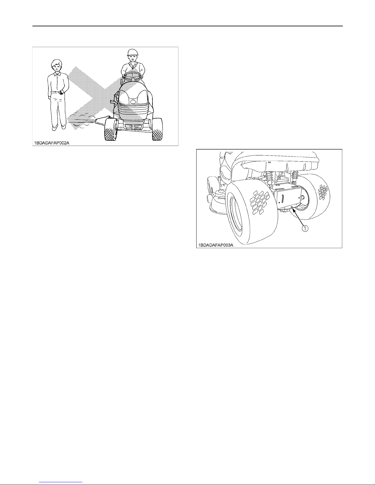
(1) Hitch hole
DO
Page 10

3SAFE OPERATION
9. If the machine stops going uphill, disengage PTO and
back slowly down.
10.Reduce speed and exercise extreme caution on
slopes and in sharp turns to prevent tip-over or loss of
control.
11.Use special caution when changing direction on
slopes.
1. Do not turn on slopes unless necessary and then turn
slowly and gradually downhill, if possible.
2. Do not mow near drop-offs, ditches, or embankments.
The machine could suddenly turn over if a wheel falls
over the edge of a cliff or ditch, or if an edge caves in.
3. Do not mow on wet grass. Reduced traction could
cause sliding.
4. Do not try to stabilize the machine by putting your foot
on the ground.
5. Do not use grass catcher on steep slopes.
6. Do not stop or start suddenly when going uphill or
downhill.
7. Never "freewheel". Do not let the machine travel
downhill with HST pedal at neutral position.
8. Do not modify or alter the machine.
C Children
Tragic accidents can occur if the operator is not alert to
the presence of children. Children are attracted to the
machine and the mowing activity. Never assume that
children will remain where you last saw them.
1. Keep children out of the mowing area and under the
watchful care of another responsible adult.
2. Be alert and turn the machine off if children enter the
area.
3. Before and when backing, look behind and down for
small children.
4. Never carry children. They may fall off and be
seriously injured or interfere with safe machine
operation.
5. Never allow children to operate the machine, even
under adult supervision.
6. Use extra care when approaching blind corners,
shrubs, trees, or other obstructions that might hide
children from sight.
C Operators, age 60 years and above
Data indicates that operators, age 60 years and above,
are involved in a large percentage of machine-related
injuries. These operators should evaluate their ability to
operate the machine safely enough to protect themselves
and others from serious injury.
C Stopping
1. Make sure that the machine has come to a complete
stop before dismounting.
2. Before dismounting, disengage the PTO, lower all
implements, place all control levers in their neutral
positions, apply parking brake, turn off the engine and
remove the key.
3. Do not park the machine on a steep incline. Park on
relatively flat areas.
1. Disengage power to attachment(s) when transporting
or not in use.
2. Do not tow this machine. Use a suitable truck or trailer
when transporting on public roads.
3. It is recommended that this machine not be used on
public roads.
4. Use extra care when loading or unloading the machine
into a trailer or truck.
1. Before servicing the machine, park the machine on a
firm, level surface, set the parking brake, stop the
engine and remove the key.
2. To avoid injury, do not adjust, unclog or service the
mower or grass catcher with the engine running. Make
sure rotating blades are stopped before dismounting
the machine.
3. Disengage power to attachment(s), stop the engine
and remove the key before making any repairs or
adjustments.
4. Allow the machine to cool off before servicing the
engine, muffler, etc.
5. Keep machine free of grass, leaves, or other debris
build-up.
6. Use extra care in handling gasoline and other fuels.
They are flammable and vapors are explosive.
a) Use only an approved container.
b) Never remove fuel cap or refuel with the engine
running. Allow engine to cool before refueling.
Do not smoke while refueling or when standing
near fuel.
c) Never refuel the machine indoors and always clean
up spilled fuel or oil.
d) Never store the machine or fuel container inside
where there is an open flame, such as in a water
heater.
7. Do not change the engine governor setting or
overspeed the engine.
8. Never run a machine inside a closed area.
9. Mower blades are sharp and can cut your hands. Wrap
the blade(s) or wear gloves, and use extra caution
when servicing them.
10.Keep nuts and bolts, especially blade attachment
bolts, tight and keep equipment in good condition.
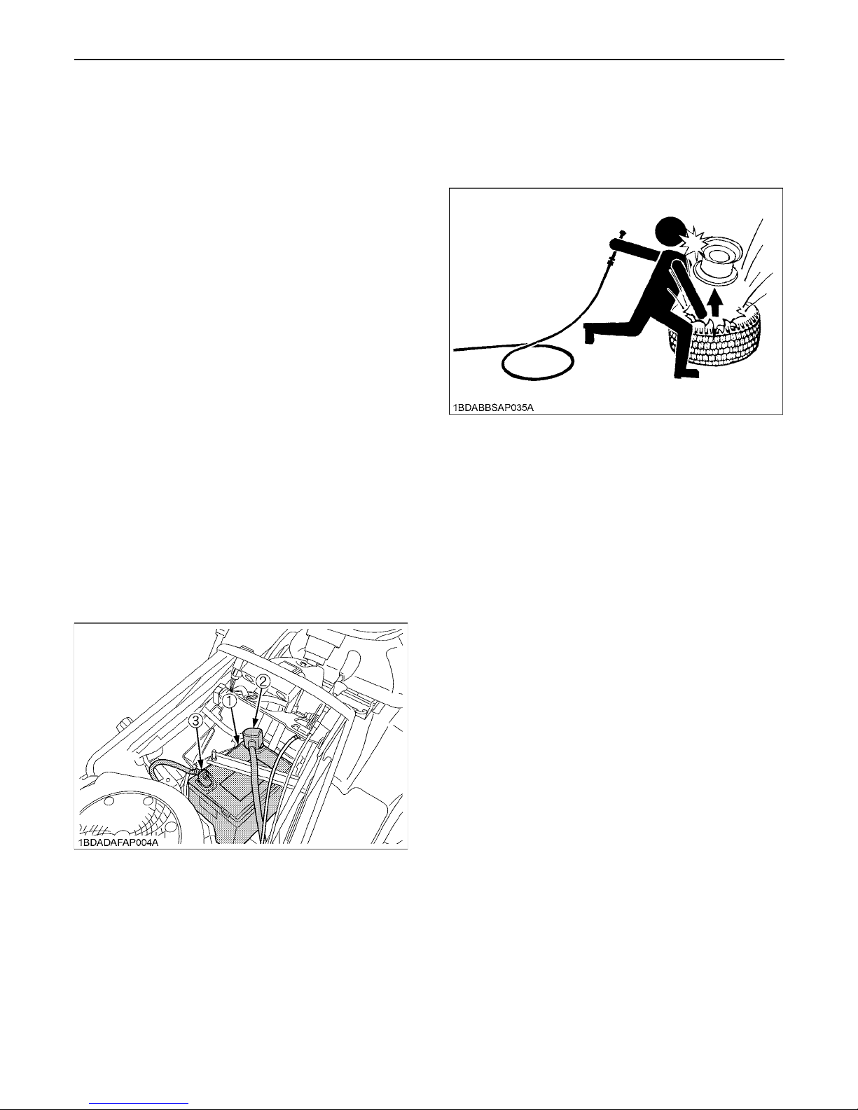
DO NOT
3. TRANSPORTING
4. SERVICING
Page 11
SAFE OPERATION4
11.Do not smoke when working around the battery.
Keep all sparks and flames away from battery. The
battery presents an explosion hazard because it gives
off hydrogen and oxygen...especially when
recharging.
12.Before "JUMP STARTING" a dead battery, read and
follow all of the instructions to help protect the
alternator from damage due to extreme load changes.
(See "JUMP STARTING" in "OPERATING THE
ENGINE" section.)
Batteries contain sulfuric acid and produce explosive
gases. Follow the instructions below to prevent
personal injury.
A Wear eye and skin protection.
A Keep sparks and flame away.
A Always have adequate ventilation while charging
or using the battery.
13.Keep first aid kit and fire extinguisher available at all
times.
14.Disconnect the battery's negative (-) cable before
working on or near electric components.
15.Do not use or charge the refillable type battery if the
fluid level is below the LOWER (lower limit level) mark.
Otherwise, the battery component parts may
prematurely deteriorate, which may shorten the
battery's service life or cause an explosion. Check the
fluid level regularly and add distilled water as required
so that the fluid level is between the UPPER and
LOWER levels.
16.To avoid sparks from an accidental short circuit,
always disconnect the battery's negative (-) cable first
and connect it last.
17.Make sure cotter pins and cir clips are properly
secured on the front and rear wheels, respectively.
18.Never tamper with safety devices.
Check their proper operation regularly.
19.Check brake operation frequently. Adjust and service
as required.
20.Properly dispose of used lubricants, filters, batteries,
and other such components.
21.Do not attempt to mount a tire on a rim. This should be
done by a qualified person with the proper equipment.
22.Always maintain the correct tire inflation pressure. Do
not inflate tires above the recommended pressure
shown in the Operator's Manual.
23.Securely support the machine when changing wheels
or the wheel tread width.
24.Make sure that wheel bolts have been tightened to the
specified torque.
1. Keep the machine and supply of fuel in locked storage
and remove the ignition key to prevent children or
others from playing or tampering with them.
2. When machine is to be stored for a long time,
disconnect battery cables or remove the battery.
Always remove the negative (-) cable first and reinstall
the negative (-) cable last.
3. Do not store the machine with fuel in the tank inside a
building where fumes may ignite. Allow the engine to
cool before storing.
4. To avoid the danger of exhaust fume poisoning, do not
operate the engine in a closed building without
adequate ventilation.
5. To reduce fire hazards, clean the machine thoroughly
before storage. Dry grass and leaves around the
engine and mufflers may ignite.
(1) Battery
(2) Positive cable (+)
(3) Negative cable (-)
5. STORAGE
Page 12
5SAFE OPERATION
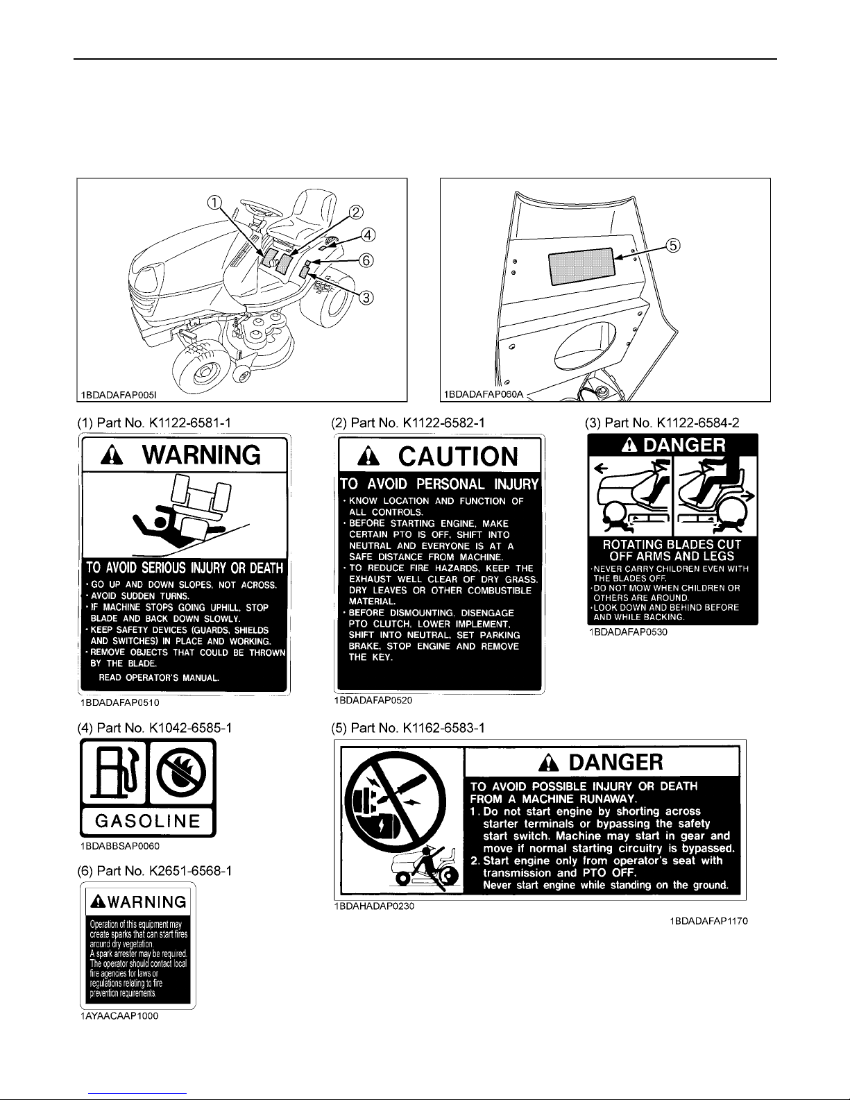
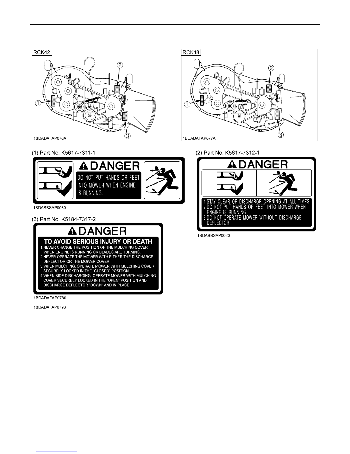
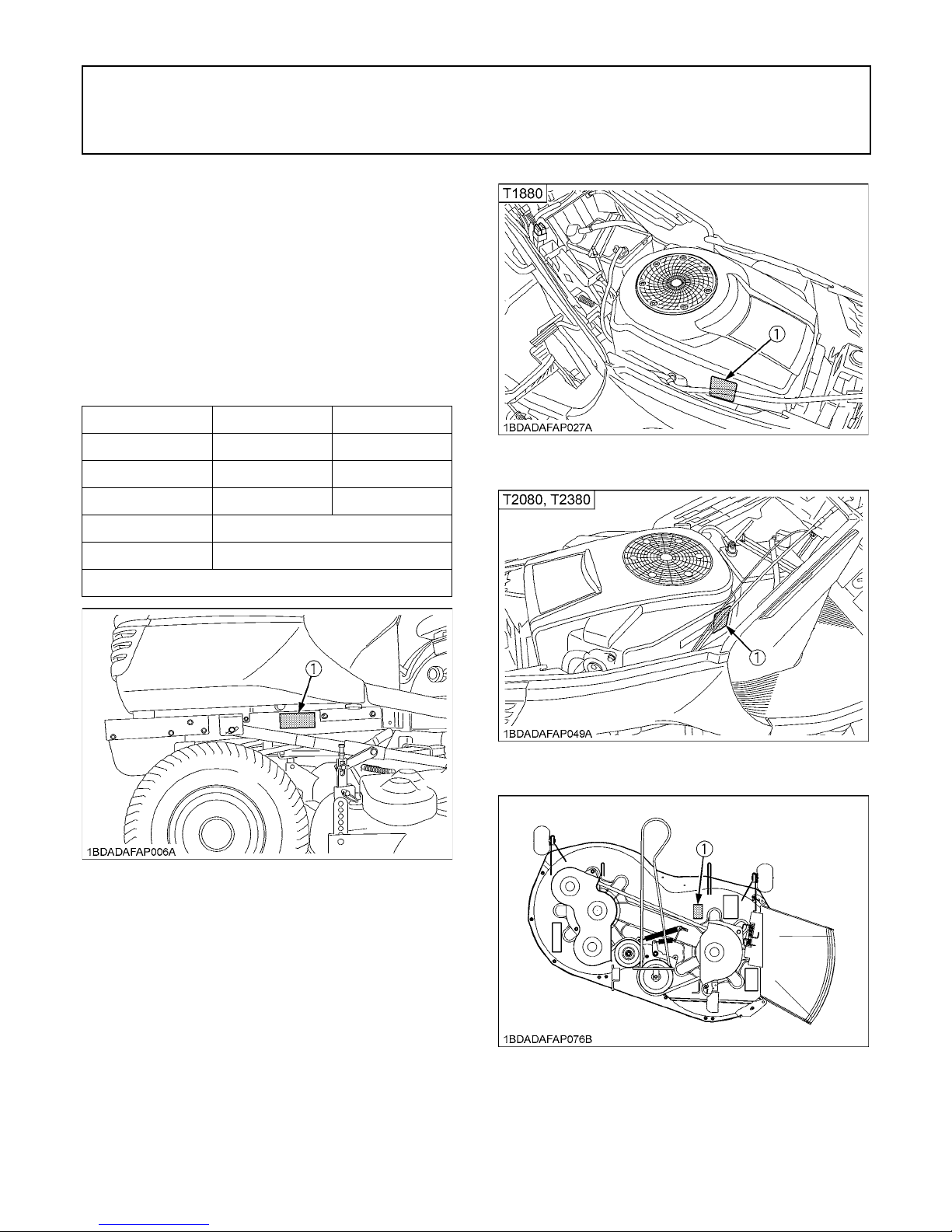
6. DANGER, WARNING AND CAUTION LABELS
Page 13
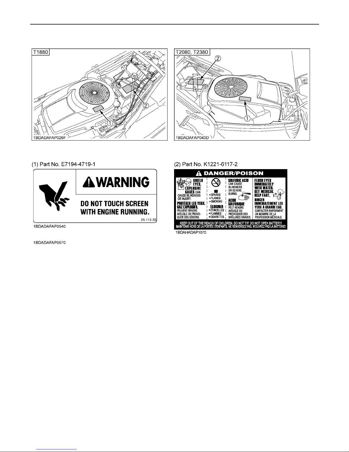
SAFE OPERATION6
Page 14
7SAFE OPERATION
1. Keep danger, warning and caution labels clean and free from obstructing material.
2. Clean danger, warning and caution labels with soap and water, and dry with a soft cloth.
3. Replace damaged or missing danger, warning and caution labels with new labels from your KUBOTA Dealer.
4. If a component with danger, warning and/or caution label(s) affixed is replaced with new part, make sure the label(s)
is(are) attached in the same location(s) as the replaced component.
5. Mount new danger, warning and caution labels by applying on a clean dry surface and pressing any bubbles to outside
edge.
7. CARE OF DANGER, WARNING AND CAUTION LABELS
Page 15

Page 16
1SERVICING OF MACHINE
SERVICING OF MACHINE
After reading this manual thoroughly, you will find that you
can do some of the regular maintenance yourself. Your
dealer is interested in helping you get the best
performance from your new machine and wants to help
you get the most value from it. When in need of parts or
major service, be sure to see your KUBOTA Dealer. When
in need of parts, be prepared to give your dealer the
machine, engine and mower serial numbers.
Locate the serial numbers now and record them in the
space provided.
Type Serial No.
Machine
Engine
Mower
Date of Purchase
Name of Dealer
(To be filled in by purchaser)
(1) Machine serial No.
(1) Engine serial No.
(1) Engine serial No.
(1) Mower serial No.
Page 17

2 SPECIFICATIONS
SPECIFICATIONS
Model T1880 T2080 T2380
Engine
Model GH540V GH710V GH720V
Type OHV air cooled gasoline engine
Number of cylinders 1 2
Total displacement cm (cu. in.) 597 (36.4) 725 (44.2)
Max.horse power kW (HP)/rpm 13.4 (18) 14.9 (20) 17.2 (23)
Cylinder bore and stroke mm (in.)
89 x 86
(3.50 x 3.38)
83 x 67 (3.27 x 2.64)
Fuel Automobile unleaded or regular gasoline
Starter Electric starter with battery
Lubrication Full pressure lubrication
Cooling Forced air cooled
Battery type U1L-9 (12V, 300CCA)
Spark plug Champion RC12YC
Capacities
Fuel tank L (U.S. gals.) 15 (3.9)
Engine crankcase L (U.S. qts.) 1.5 (1.6) 1.8 (1.9)
Hydrostatic transmission case L (U.S. qts.) 2.75 (2.9)
Machine
PTO Belt
Direction of revolution Clockwise viewed from top
Revolution (PTO speed) rpm 3200
PTO clutch Belt tension
Transmission Hydrostatic transmission
Traveling speeds
Forward km/h (mph) 0 to 9.0 (0 to 5.6)
Reverse km/h (mph) 0 to 5 (0 to 3.1)
Brake External disktype
Tires
Front 15 x 6.00-6
Rear 22 x 11.00-10
Dimensions
Overall length mm (in.) 1850 (72.8)
Overall width (with mower) mm (in.) 1392 (54.8) 1544 (60.8)
Overall height mm (in.) 1090 (42.9) 1125 (44.3)
Wheelbase mm (in.) 1290 (50.8) 1380 (54.3)
Treads
Front mm (in.) 783 (30.8)
Rear mm (in.) 727 (28.6)
Weight (with mower) kg (lbs.) 280 (617) 285 (628)
Page 18

3SPECIFICATIONS
NOTE: *Manufacturer's estimate. The company reserves the right to change the specifications without notice.
Mower
Type RCK42-LT20 RCK48-LT23
Mounting method Parallel Linkage
Adjustment of cutting height Dial gauge
Cutting width mm (in.) 1067(42) 1219 (48)
Cutting height mm (in.) 25 to 102 (1.0 to 4.0)
Weight (Approx.) kg (lbs.) 51 (112.5) 58 (127.9)
Number of blades 2
Dimensions
Total length mm (in.) 868 (34.2) 957 (37.7)
Total width mm (in.) 1358 (53.5) 1521 (59.9)
Total height mm (in.) 295 (11.6)
Discharge Right Side
Model T1880 T2080 T2380
Page 19
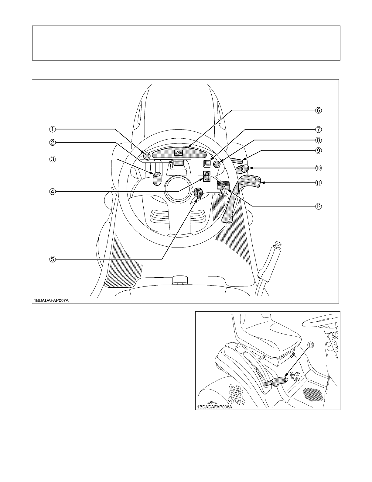
4 INSTRUMENT PANEL AND CONTROLS
INSTRUMENT PANEL AND CONTROLS
(1) Choke knob
(2) Hour meter (option)
(3) Throttle lever
(4) Light switch
(5) Key switch
(6) Easy checker (TM)
(7) KRA system switch
(8) Cruise control knob (T2080, T2380)
(9) Parking brake lock pedal
(10) PTO lever
(11) Speed control pedal
(12) Brake pedal
(13) Lift lever
Page 20
5MOWER MOUNTING
MOWER MOUNTING
ATTACHING THE MOWER
To avoid personal injury:
A Shut off the engine and remove the key before
attaching the mower.
1. Park the machine on level ground and place the
mower deck at the right side of machine.
Raise mower lift lever and lock in raised position.
2. Turn the front wheels to the left. Slide the mower under
the machine, then return wheels to straight ahead
position. Adjust height control dial to 1" and lower
mower lift lever and lock in lower position.
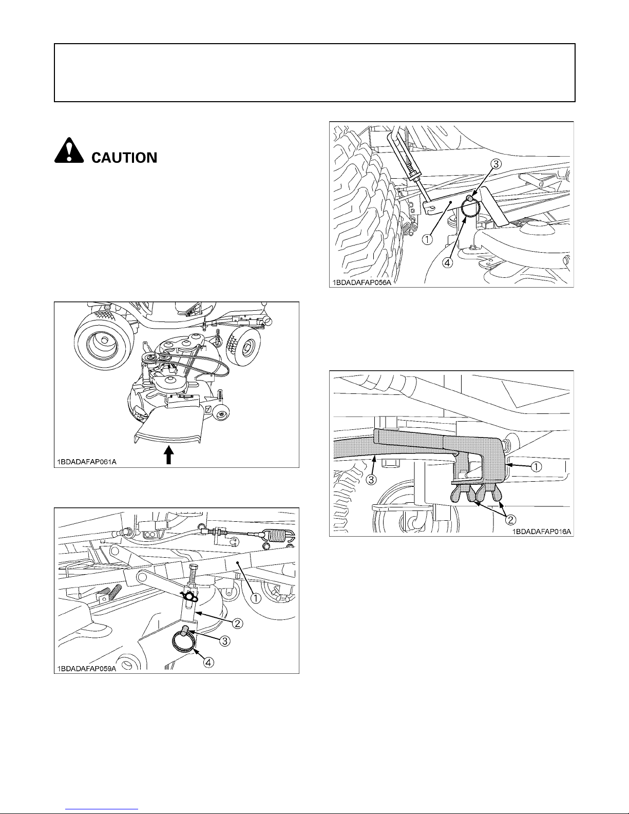
3. Attach the mower deck to the link and mower link with
four clevis pins and snap rings.
4. Attach the PTO belt to the engine pulley then attach
the belt support bracket.
(1) Mower link
(2) Link
(3) Clevis pin
(4) Snap ring
(1) Belt support bracket
(2) Wing bolt
(3) PTO belt
Page 21
MOWER MOUNTING6
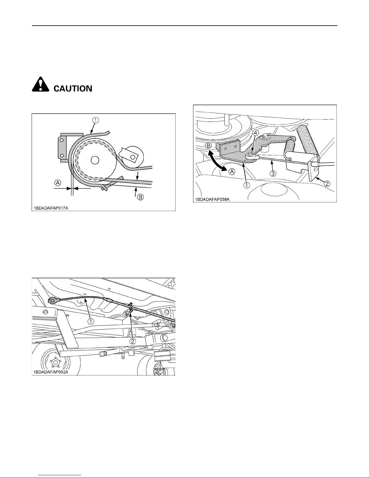
[Belt support bracket attaching and adjustment]
Adjust the belt support bracket to the following
specification with the PTO lever in the "ENGAGED"
position and tighten the belt support bracket.
To avoid personal injury:
A Make sure engine is not running.
5. Remove the mower brake wire clamped under the
step.
6. After passing the mower brake wire through the wire
holder, attach it to the mower brake with the rue ring
cotter pin.
7. The mower brake is a safety device to stop the blades.
When the PTO lever is in the "DISENGAGED"
position, the brake is applied to the pulley groove and
the blade stops turning in a very short time. With the
PTO lever at the "ENGAGED" position, the brake is off
the pulley groove and the pulley is allowed to turn.
(1) Belt support bracket (A) Clearance between belt support
bracket and pulley. 1 to 2 mm
(3/64" to 5/64")
(B) Clearance between belt support
bracket and belt. 6 to 7 mm
(15/64" to 9/32")
(1) Mower brake wire
(2) Clamp
(1) Mower brake
(2) Wire holder
(3) Mower brake wire
(4) Rue ring cotter pin
(A) PTO lever "ENGAGED"
(B) PTO lever "DISENGAGED"
Page 22
7MOWER MOUNTING
To avoid personal injury:
A Make sure engine is not running when
adjusting the brake.
A Do not operate mower when the brake is not
properly adjusted.
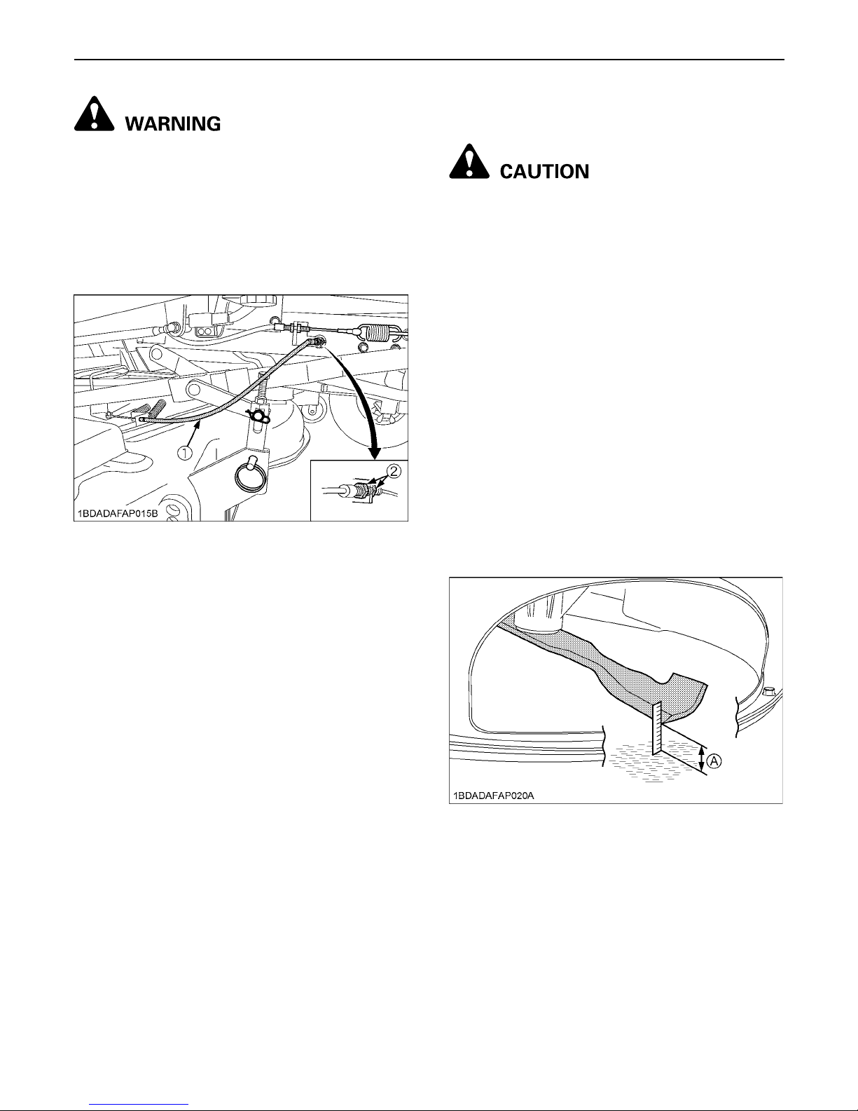
8. Check mower brake performance by repeatedly
switching the PTO lever from "ENGAGED" to
"DISENGAGED". Adjust the mower brake wire if
necessary.
ADJUSTING THE MOWER DECK (FOR
BEAUTIFUL FINISH CUT)
To avoid personal injury:
A Shut off the engine and remove the key.
A Set parking brake.
A Allow the blades to stop before making
adjustments.
A Blades may be sharp. When you handle blades,
wear heavy gloves or wrap end of blade with a
rag.
1. Park the machine on a level surface.
2. Tire inflation pressure must be correct.
(See "EVERY 50 HOURS" in "PERIODIC SERVICE"
section.)
3. Raise the lift lever to the top position. Turn the cutting
height control dial to adjust height to the desired
height.
4. Lower the mower deck by pushing the lift lever
downward.
5. Turn left blade so that it is parallel to rear axle.
Hold drive belt and turn right blade so that it is parallel
to axle.
6. Measure from each outside blade tip (Left) to (Right)
to the level surface. The difference between
measurements should be less than 3 mm (1/8 in.).
(1) Mower brake wire
(2) Adjustment nuts
(A) Blade tip height
Page 23

MOWER MOUNTING8
7. Loosen the nuts.
Adjust the link, lift link and lift rod length so that the
difference between measurements (Left) and (Right)
is less than 3 mm (1/8 in.).
8. Adjust the blade height so that the rear blade is 5 mm
(0.2 in.) higher than the front blade.
9. Tighten the nuts.
(1) Link
(2) Nut
(1) Lift link
(2) Lift rod
(3) Nut
A Make sure the rear blade is higher than the front
blade; otherwise beautiful finish cut can't be
obtained.
(A) Front
(B) Rear
Page 24

9MOWER MOUNTING
[For the mower with serial number below]
(RCK42-LT20) 14218 and above
(RCK48-LT23) 11927 and above
10.Measure from the outside tip of the right blade to the
level surface (while the blade is parallel to the rear
axle). This will be measurement C.
11.Measure from the level surface to the bottom of the
discharge cover at point D as shown in the picture
below. This will be measurement D.
12.The difference between measurement D and C should
be 88 mm.
If not, adjust by loosening the bolt and moving the
Plate Discharge Stopper.
To avoid personal injury:
A Make sure D-C is not more than 88 mm.
(A) Measurement C
(B) Mower cover
(A) Bent mark line
(A) Measurement D
(A) Plate discharge stopper
(B) Mower cover
(C) Mower deck upper surface
Page 25

10 OPERATING THE ENGINE
OPERATING THE ENGINE
To avoid personal injury:
A Read "SAFE OPERATION" in the front of this
manual.
A Read the danger, warning and caution labels
located on the machine.
A To avoid danger of exhaust fume poisoning, do
not operate the engine in a closed building
without proper ventilation.
A Never start the engine while standing on the
ground. Start the engine only from the
operator's seat.
STARTING THE ENGINE
BParking Brake Lock Pedal
A To apply the parking brake, depress the brake pedal
and the parking brake lock pedal simultaneously with
your right foot. Then release the brake pedal while
holding the parking brake lock pedal down.
A To release the parking brake, depress the brake pedal
and release slowly with your right foot.
A This machine is equipped with safety devices.
If you dismount from the seat and the parking brake is
not applied, the engine will stop automatically.
(Operator presence control)
[T1880]
The operator's seat position can be adjusted forward and
rearward. Loosen the seat adjustment knob, slide the seat
to the desired position and then retighten the knob.
1. Apply the parking brake.
(1) Brake pedal
(2) Parking brake lock pedal
(A) "DEPRESS"
(B) "PUSH FORWARD WHILE
DEPRESSING (1)"
2. Make sure that the PTO lever is in the
"DISENGAGED" position.
(1) PTO lever : "ENGAGED"
: "DISENGAGED"
3. Adjusting the operator's position.
(1) Seat adjustment knob
Page 26

11OPERATING THE ENGINE
[T2080, T2380]
The operator's seat position can be adjusted forward and
backward by pulling the seat sliding lever.
A If engine is cold,
Pull the choke knob out.
A If engine is warm,
Move the throttle lever to "HALF SPEED" position.
BThrottle Lever & Choke Knob
Pulling the throttle lever downward decreases the engine
speed and pushing it upward increases the engine speed.
Always pull the choke knob out to the "ON" position to
start the engine in cold conditions.
Always push choke knob in to the "OFF" position after the
engine has started.
BKey Switch
A To avoid damage to the starter, do not operate starter
more than 5 seconds at a time. If engine does not start,
wait 10 seconds before trying again.
A Do not turn the key to the "START" position while the
engine is running.
A Do not operate the machine under full load condition
until it is sufficiently warmed up 2 or 3 minutes for
temperatures above 0 (32 ).
(1) Seat sliding lever
4. Set the throttle lever as follows.
(1) Throttle lever
(2) Choke knob
: "FAST"
: "SLOW"
(A) Pull out: "ON" position
(B) Push in: "OFF" position
5. Insert the key into the key switch. Turn
the key switch to "START" position and
release key to "ON" position when the
engine starts.
OFF... The position where the key can be inserted
into or removed from the key switch. [When
the key is turned to this position, the engine
shuts off.]
ON..... The engine is running.
Start... Depress the brake pedal fully and pull the PTO
lever to the "DISENGAGED" position, turn the
key switch to this position to start the engine.
: "OFF"
: "ON"
: "START"
Page 27

OPERATING THE ENGINE12
COLD WEATHER STARTING
If the ambient temperature is below 0 (32 ) and the
engine is very cold, start it in the following manner:
1. Pull the choke knob out.
2. Turn the key switch to the START (" ") position.
A Operate starter 5 seconds.
A If engine does not start, wait 10 seconds.
A Repeat this procedure until engine starts.
3. When the engine starts, release key to ON (" ")
position.
4. Move the throttle lever to "HALF SPEED" position.
A When the temperature is below 0 (32 ). Keep the
engine at medium speed to warm up the lubricant of
engine and transmission at least 10 minutes. If the
machine is operated before the lubricant of engine and
transmission is warmed sufficiently, the machine life
will be shortened.
A Do not operate the machine under full load condition
until it is sufficiently warmed up.
CHECKING SAFETY DEVICES
1. Check the following tests before operating the mower.
Sit on the operator's seat for all tests.
2. If the machine does not pass one of the following tests,
do not operate the machine.
Contact your KUBOTA Dealer.
C Safety Start Control 1
1. Depress the brake pedal fully.
2. Engage the PTO lever.
3. Turn the key switch to the "START" position.
4. The engine should not crank.
C Safety Start Control 2
1. Disengage the PTO lever.
2. Release the brake pedal.
3. Turn the key to "START" position.
4. The engine should not crank.
C Seat Safety Control 1
1. Run the engine at half throttle.
2. Engage the PTO lever.
3. Stand up. (DO NOT GET OFF THE MACHINE.)
4. Engine should shut off.
C Seat Safety Control 2
1. Run the engine at half throttle.
2. Disengage PTO lever.
3. Release the brake pedal.
4. Stand up. (DO NOT GET OFF THE MACHINE.)
5. Engine should shut off.
C KUBOTA Reverse Awareness system
(KRA system) 1
1. Start and run the engine at half throttle.
2. Engage the PTO lever.
3. Press slightly on reverse side of speed control pedal.
4. Engine should shut off.
C KUBOTA Reverse Awareness system
(KRA system) 2
1. Start and run the engine at 1/4 throttle.
2. Engage the PTO lever.
3. Press the KRA system override switch.
4. The KRA indicator light should flash.
5. Press slightly on the reverse side of speed control
pedal.
6. Engine should not shut off.
Remove the fuse from under the seat before test 3
C KUBOTA Reverse Awareness system
(KRA system) 3
1. Start and run the engine at 1/4 throttle.
2. Engage the PTO lever.
3. Press the KRA system override switch.
4. The KRA indicator light should not flash.
5. Press slightly on reverse side of speed control pedal.
6. Engine should shut off.
Page 28

13OPERATING THE ENGINE
CHECK WHILE OPERATING THE ENGINE
- Check color of the exhaust fumes.
- Check the headlights.
- Check performance of the PTO clutch.
- Check safety switch, seat safety control, and PTO
safety control.
If one of these do not operate properly, contact your
KUBOTA Dealer immediately.
- Check for abnormal noise and vibration.
- Check Easy Checker (TM).
STOPPING THE ENGINE
1. Keep the engine at 1/2 to 3/4 throttle and
turn the key switch to the "OFF" position.
2. Remove the key.
3. Do not leave the key switch "ON" (key in
the "ON" position) as the battery will
discharge when the engine is not running.
4. Set the parking brake.
(1) Brake pedal
(2) Parking brake lock pedal
(A) "DEPRESS"
(B) "PUSH FORWARD WHILE
DEPRESSING (1)"
5. Close the fuel valve.
(1) Fuel valve (A) "OPEN"
(B) "CLOSE"
Page 29

OPERATING THE ENGINE14
WARMING UP
To avoid personal injury:
A Be sure to apply the parking brake during
warm-up.
For 5 minutes after engine start-up, allow engine to warm
up without applying any load. This is to allow oil to reach
every engine part. If load should be applied to the engine
without this warm-up period, trouble such as seizure,
breakage or premature wear may develop.
BWarm-up and Transmission Oil in the Low
Temperature Range
Hydraulic oil serves as transmission fluid. In cold weather,
the oil may be cold with increased viscosity.
This can cause delayed oil circulation or abnormally low
hydraulic pressure for some time after engine start-up.
This in turn can result in trouble in the hydraulic system.
To prevent the above, observe the following instructions:
Warm up the engine at about 50% of rated rpm according
to the table below:
A Do not operate the machine under full load condition
until it is sufficiently warmed up.
Ambient temperature Warm-up time requirement
Higher than 0 (32 ) Approx. 5 minutes
0 to -10 (32 to 14 ) 5 to 10 minutes
-10 to -20 (14 to -4 ) 10 to 15 minutes
Below -20 (-4 ) More than 15 minutes
Page 30

15OPERATING THE ENGINE
JUMP STARTING
To avoid personal injury:
A Battery gases can explode. Keep cigarettes,
sparks, and flames away from battery.
A If machine battery is frozen, do not jump start
engine.
A Do not connect other end of negative (-) jumper
cable to negative (-) terminal of machine
battery.
When jump starting engine, follow the instructions below
to safely start the engine.
1. Bring helper vehicle with a battery of the same voltage
as disabled machine within easy cable reach. "THE
VEHICLES MUST NOT TOUCH".
2. Apply the parking brakes of both vehicles and put the
shift levers in neutral. Shut the engine off.
3. Put on safety goggles and rubber gloves.
4. Ensure the vent caps are securely in place.
(if equipped)
5. Cover vent caps with damp rags. Do not allow the rag
to touch the battery terminals.
6. Attach the red clamp to the positive (red, (+) or pos.)
terminal of the dead battery and clamp the other end
of the same cable to the positive (red, (+) or pos.)
terminal of the helper battery.
7. Clamp the other cable to the negative (black, (-) or
neg.) terminal of the helper battery.
8. Clamp the other end to the engine block or frame of
the disabled machine as far from the dead battery as
possible.
9. Start the helper vehicle and let its engine run for a few
moments. Start the disabled machine.
10.Disconnect the jumper cables in the exact reverse
order of attachment. (Steps 8, 7 and 6).
11.Remove and discard the damp rags.
A This machine has a 12 volt negative (-) ground starting
system.
A Use only same voltage for jump starting.
A Use of a higher voltage source on machine could
result in severe damage to machine electrical system.
Use only matching voltage source when "Jump
starting" a low or dead battery condition.
(1) Dead battery
(2) Lay a damp rag over the vent caps
(3) Jumper cables
(4) Engine block or frame
(5) Helper battery
Connect cables in numerical order.
Disconnect in reverse order after use.
Page 31

16 OPERATING THE MACHINE
OPERATING THE MACHINE
OPERATING NEW MACHINE
How a new machine is operated and maintained
determines the life of the machine.
A new machine just off the factory production line has
been, of course, tested, but the various parts are not
accustomed to each other, so care should be taken to
operate the machine for the first 50 hours at a slower
speed and avoid excessive work or operation until the
various parts become "broken-in." The manner in which
the machine is handled during the "breaking-in" period
greatly affects the life of your machine. Therefore, to
obtain the maximum performance and the longest life of
the machine, it is very important to properly break-in your
machine. In handling a new machine, the following
precautions should be observed.
BChanging Lubricating Oil for New
Machines
The lubricating oil is especially important in the case of a
new machine. The various parts are not "broken-in" and
are not accustomed to each other; small metal grit may
develop during the operation of the machine; and this may
wear out or damage the parts. Therefore, care should be
taken to change the lubricating oil a little earlier than
would ordinarily be required.
For further details of change interval hours, see
"SERVICE INTERVALS" in "MAINTENANCE" section.
To avoid serious injury or death:
A Do not operate the mower without the deflector
shield in the down position nor the mulching
cover in front.
To avoid serious injury:
A Do not allow any person other than the driver to
ride on the machine.
A Do not drive the machine close to the edges of
ditches or banks which may collapse under the
weight of the machine, especially when the
ground is loose or wet.
A Slow down before turning.
A To avoid tip over, operate up and down slopes,
not across. Avoid sudden starts and stops on
slopes. Slow down, and use extra caution when
changing direction on a slope. Do not use the
machine on steep incline.
Park the machine on a firm, level surface.
A Watch where you are going at all times. Watch
for and avoid obstacles. Be alert at curbs, near
trees, and other obstructions and hidden
hazards.
A Do not drive a machine on streets or highways.
Watch for traffic when you cross roads or
operate near roads.
A Look to the rear before and when backing.
Make sure the area immediately behind you is
clear of obstructions or holes and small
children. Use extra caution when a machine is
equipped with Grass Catcher.
To avoid personal injury:
A Clear the work area of objects which might be
picked up and thrown by blades.
A Do not direct the opening of the chute at
bystanders or animals. Ejected objects may
cause injury. Plan your mowing carefully
before starting operation.
A Keep bystanders especially children and
animals away from the mowing area.
A Be sure to disengage the PTO and sit on the
operator's seat before starting the engine.
Page 32

17OPERATING THE MACHINE
STARTING
BSeat
To avoid personal injury:
A Make sure that the seat is completely secured
after each adjustment.
A Do not allow any person other than the driver to
ride on the machine.
[T1880]
The operator's seat position can be adjusted forward and
rearward. Loosen the seat adjustment knob, slide the seat
to the desired position and then retighten the knob.
[T2080, T2380]
The operator's seat position can be adjusted forward and
backward by pulling the seat sliding lever.
BLight Switch
Pushing the light switch upward illuminates the headlights
and pushing it downward turns the lights off.
BLift Lever
The lift lever is used to raise and lower the mower deck.
To raise the mower deck, lift the lever slightly, then push
the button at the top of the lift lever, and pull the lever
upward.
To lower the mower deck, lift the lever slightly, then push
the button at the top of the lift lever, hold the button in and
lower the lever down.
1. Adjust the operator's position.
(1) Seat adjustment knob
(1) Seat sliding lever
2. Select Light Switch Positions.
(1) Light switch : "ON"
: "OFF"
3. Raise the implement.
(1) Lift Lever
(2) Button
"RAISE"
"LOWER"
Page 33

OPERATING THE MACHINE18
BThrottle Lever
Pulling the throttle lever backward decreases the engine
speed and pushing it forward increases the engine speed.
BParking Brake
To release the parking brake, depress the brake pedal
again.
BSpeed Control Pedal
"FORWARD"
Depress the speed control pedal with the toe of your right
foot to move forward.
"REVERSE"
Depress the speed control pedal with the heel of your right
foot to move in reverse.
Depress the speed control pedal a little and you can drive
slowly.
To increase travel-speed, depress the speed control
pedal more until the desired speed is reached.
A When the parking brake is applied, the speed control
pedal is locked in the neutral position.
4. Accelerate the Engine.
(1) Throttle lever : "FAST"
: "SLOW"
5. Unlock the Parking Brake.
(1) Brake pedal (A) "DEPRESS"
6. Depress the Speed Control Pedal.
(1) Speed control pedal (A) "FORWARD"
(B) "REVERSE"
Page 34

19OPERATING THE MACHINE
BCruise Control Device
[T2080, T2380]
The cruise control device is designed for machine
operating efficiency and operator's comfort. This device
will provide a constant forward operating speed by
mechanically holding the speed control pedal at a
selected position.
C To engage cruise control device
1. Accelerate speed to desired level using speed control
pedal.
2. Pull the cruise control knob.
3. Release the speed control pedal while pulling the
cruise control knob.
4. Release the cruise control knob and desired speed will
be maintained.
C To disengage speed set device
A Step on the forward acceleration side of the pedal or
depress the brake pedal.
A Cruise control device will not operate in reverse.
A To prevent the damage of cruise control device, do not
depress the reverse pedal when the cruise control
device is engaged.
(1) Speed control pedal (A) "FORWARD"
(B) "REVERSE"
(1) Cruise control knob : "ENGAGED"
Page 35

OPERATING THE MACHINE20
STOPPING
CHECK DURING DRIVING
BImmediately Stop the Engine if:
A The engine suddenly slows down or accelerates.
A Unusual noises are suddenly heard.
A Exhaust fumes suddenly become discolored.
While driving, make the following checks to see that all the
parts are functioning normally.
BEasy Checker (TM)
A To avoid inaccurate accumulation of indicated
operating hours, turn the key switch to "OFF" when the
engine is not running.
BHourmeter (option)
The hourmeter indicates in five digits the hours the
machine has been used; the last digit indicates 1/10 of an
hour.
A As the hour meter works electrically, it starts to work
when the key switch is turned to "ON", regardless of
the engine running or not.
1. Release the speed control pedal and
depress the brake pedal to stop the
machine.
2. Pull the PTO lever to the "DISENGAGED"
position.
3. Slow the engine down.
(A) If this warning light comes on during operation, stop the
engine immediately and check level of engine oil.
(See "Checking Engine Oil Level" in "DAILY CHECK" in
"PERIODIC SERVICE" section.)
(1) Hour meter
Page 36

21OPERATING THE MACHINE
PARKING
BParking
To avoid personal injury:
Before leaving the operator's position:
A Apply parking brake.
A Lower all implements to the ground.
A Shut off the engine.
A Remove the key.
1. When parking, be sure to set the parking brake.
To apply the parking brake;
Depress the brake pedal firmly and the parking brake
lock pedal simultaneously with your right foot. Then
release the brake pedal while holding the parking
brake lock pedal down.
2. Before getting off the machine, disengage the PTO,
lower all implements to the ground, set the parking
brake, stop the engine and remove the key.
3. If it is necessary to park on an incline, be sure to chock
the wheels to prevent accidental rolling of the
machine.
TRANSPORTING
1. Transport the machine on a trailer.
A Fasten the machine to the trailer.
A To prevent the hood from opening by wind while in
transit, it is necessary to either load the machine
forward or use a suitable tie down for the hood.
2. Do not attempt to tow this machine, or damage to the
transmission may result.
BHydrostatic Transaxle Bypass Rod
A Do not push the machine without pulling the bypass
rod or transmission damage may occur.
A Never pull the rod with the engine running.
1. To push the machine, pull the HST bypass rod and
hold it.
2. After moving the machine, release the rod and it will
return automatically to normal position.
(1) Chocks
(1) HST bypass rod
Page 37

22 OPERATING THE MOWER
OPERATING THE MOWER
MAKING THE MOST OF YOUR MOWER
1. When using your mower for the first time, choose a
smooth level area and cut in straight and slightly
overlapping strips.
2. The size and type of the area to be mowed will
determine the proper mowing pattern. Take into
account obstructions, such as trees, fences and
buildings. To keep grass clippings off fences,
sidewalks, etc., it is advisable to go over the outside of
the area to be mowed several times in a clockwise
direction. To mow the area remaining, work in a
counterclockwise direction so that the clippings are
dispersed onto the previously cut area.
3. Always keep the left side of the mower toward trees,
posts or other obstacles on the first trip around the
obstacle.
4. Most lawns should be mowed to keep the grass
approximately 50 to 80 mm (2 to 3 in.) high. Best
results are obtained by cutting often and not too short.
To keep a green lawn, never mow more than one third
of the height of the grass or a maximum of 25 mm (1
in.) in one mowing.
For extremely tall grass, set the cutting height at
maximum cutting height for the first mowing, then
reset to the desired height and mow again. Allow the
grass to grow to 80 mm (3 in.), then cut off only the top
inch.
5. For best appearance, grass should be cut in the
afternoon or evening when it is free of moisture.
To avoid personal injury:
A Clear the work area of objects which might be
picked up and thrown by blades.
A Keep bystanders and animals away from the
mowing area.
A Be sure to disengage the PTO and sit on the
operator's seat before starting the engine.
ADJUSTING CUTTING HEIGHT
To avoid serious injury or death:
A Do not operate mower in the "TOP" position.
BCutting Height Control Dial
Raise the lift lever to the top position. Turn the cutting
height control dial to the desired cutting height. Then
lower the lift lever and the mower deck will be set to the
cutting height.
1. Before adjusting the cutting height, check that all tire
pressures are correct. If necessary, adjust to the
correct tire pressure.
2. To set the cutting height, pull the mower lift lever up to
raise the mower deck to the "TOP" position.
3. Turn the cutting height control dial to adjust the height.
4. Set the anti-scalp rollers' height as shown to keep
clearance between rollers and ground more than 6
mm (0.25 in.).
(1) Cutting height control dial
(2) Lift lever
"RAISE"
"LOWER"
Page 38

23OPERATING THE MOWER
5. Lower the mower deck by pushing the mower lift lever
downward. This lowers the mower deck from the
"TOP" position to the "OPERATING" position.
6. Use the higher settings for mowing in a rough area or
when mowing tall grass. Lower settings should be
used only for smooth lawns where short grass is
desired.
OPERATING THE MOWER
A This machine is equipped with the KRA (KUBOTA
Reverse Awareness) system.
This feature shuts down the engine if the operator
attempts reverse travel while any PTO driven
implement is engaged. The purpose of the KRA
system is to increase operator awareness of the risk of
back-over accidents. The KRA system incorporates an
override switch on the dash that allows the operator to
override the system and keep the PTO engaged
during reverse travel. KUBOTA strongly recommends
against overriding the KRA system, but if the operator
deems it absolutely necessary and safe to do so, he
may activate the override switch. The override switch
light flashes while activated as a reminder to the
operator that the PTO (i.e. mower, grass catcher,
snowblower, etc.) remains engaged during reverse
travel. The operator should return the KRA system to
normal operating mode as soon as possible by
momentarily disengaging the PTO.
BKRA system Normal Operating Mode
1. Start the engine.
2. Set the throttle lever to the "FAST" position.
3. Push down the PTO lever to the "ENGAGED" position.
(1) Anti-scalp roller
(1) Throttle lever : "FAST" position
: "SLOW" position
Page 39

OPERATING THE MOWER24
BPTO Lever
To engage mower blades, push the PTO lever to the
"ENGAGED" position. To stop the mower blades, pull the
PTO lever to the "DISENGAGED" position.
A When attempting to operate the machine in reverse
with the PTO engaged, the engine will shut down.
A If you dismount from the seat while the PTO is running,
the engine will stop automatically. (Operator Presence
Control)
A Before starting the engine, pull the PTO lever to the
"DISENGAGED" position and depress brake pedal,
otherwise, the starter will not operate.
A For best cut quality and performance, always mow
with the throttle lever in "FAST" position.
Use the speed control pedal to select the desired mowing
speed range.
1. Control ground speed by using the speed control
pedal of the machine.
A Keep the mower deck in the fully raised position when
the mower is not engaged.
BKRA system Override Mode
To avoid personal injury:
A Before and when backing, look down and
behind the machine to be sure no bystanders,
especially children, have entered the area.
A K.R.A. System override switch allows the operator to
mow or operate attachments while in reverse if the
operator deems it absolutely necessary and safe to do
so. (i.e. the operator should make sure that no
bystanders, especially children, have entered the
area.)
If the owner does not wish certain operators to utilize
the override switch allowing mowing or implement
operation in reverse, then he or she may remove the
fuse from the system to prevent override. (See NOTE
(4) below)
1. Start the engine.
2. Set the throttle to the "FAST" position.
3. Push the PTO lever to the "ENGAGED" position.
4. Stop the machine (Set the speed control pedal to
NEUTRAL) or depress the speed control pedal
forward.
5. Push the K.R.A. System override switch.
6. Look down and behind the machine to be sure that no
bystanders, especially children have entered the area.
7. Depress the speed control pedal with the heel of your
right foot to move in the reverse direction.
(1) PTO lever : "ENGAGE"
: "DISENGAGE"
(1) During heavy duty use, operate the machine at a
slower ground speed or go over the area twice.
The first pass should be with the deck at the highest
cutting position, then mow to desired height.
(2) The mower will not cut cleanly if the ground speed is
too high or if the blade speed drops due to an
overload.
(1) K.R.A. System switch
Page 40

25OPERATING THE MOWER
To avoid serious injury or death:
A Engine components can get extremely hot from
operation. To prevent severe burns, do not
touch these areas while the engine is running,
or immediately after it is turned off.
Never operate the engine with heat shields or
guards removed.
WHEN OPERATING MULCHING
FUNCTION
To avoid personal injury:
A Shut off the engine and remove the key.
1. Park the machine on the firm and level surface.
2. Unlatch the clamp holding the mulching cover.
(1) The K.R.A. System Override Mode can not be
activated by pushing the switch while the speed
control pedal is depressed to initiate rearward
movement.
(2) The override switch light flashes while activated as
a reminder to the operator that PTO (i.e. mower,
grass catcher, snow blower, etc.) remains engaged
during reverse travel.
(3) The K.R.A. System Override Mode will remain
activated until the PTO lever is returned to the
"DISENGAGED" position.
(4) To prevent use of the K.R.A. System Override
Mode, remove the fuse located under the seat:
A The engine can be started.
A The machine PTO can be engaged if the speed
control pedal is in the neutral or forward position.
A Selection of PTO operation (i.e. mower, grass
catcher, snow blower, etc.) during reverse travel
is not possible.
(1) Fuse
(1) Mulching cover
(2) Clamp
Page 41

OPERATING THE MOWER26
3. Unhook the mulching cover in the back.
(1) Slide the mulching cover a little backward.
(2) Lift the mulching cover slightly and unhook it.
4. Lift the discharge deflector and the mower cover.
5. While lifting the mulching cover a little, move the
mulching cover forward and hook the rear of the cover
onto the deck.
Release the mower cover and discharge deflector
then place them on the stay of mulching cover.
(1) Mulching cover (A) "SLIDE"
(1) Mulching cover (A) "LIFT"
(1) Discharge deflector
(2) Mower cover
(3) Mulching cover
(1) Discharge deflector
(2) Mower cover
(3) Mulching cover
(4) Stay of mulching cover
Page 42

27OPERATING THE MOWER
6. Fasten the clamp of the mulching cover and make sure
the cover is fixed to the mower deck securely with no
gap for discharge.
To avoid personal injury:
A Do not operate the mower with the mulching
cover not certainly hooked.
TO CHANGE THE OPERATING MODE
FROM MULCHING TO SIDE DISCHARGE
To avoid personal injury:
A Shut off the engine and remove the key.
To change the mode, reverse the procedures in "WHEN
OPERATING MULCHING FUNCTION".
1. Park the machine on the firm and level surface.
2. Lift the discharge deflector and the mower cover.
3. Unlatch the clamp of the mulching cover.
4. While lifting the mulching cover a little, move the
mulching cover backward and hook in the back
securely.
5. Put back the discharge deflector and the mower cover
to the original position.
6. Fasten the clamp of the mulching cover and make sure
it is fixed to the mower deck securely.
To avoid personal injury:
A Do not operate the mower with the mulching
cover not certainly hooked.
(1) Mower deck
(2) Clamp
Page 43

OPERATING THE MOWER28
ADJUSTING THE CLAMP
To avoid personal injury:
A Shut off the engine and remove the key.
Make sure the mulching cover is fixed securely. If not,
adjust the clamp stay and the hook plate to fix it.
BSide Discharge Position
1. Hang the rear part of the mulching cover on the hook
in the rear of the mower deck.
2. Loosen the bolts of the clamp stay.
3. While pushing the mulching cover to the mower deck
stopper, fasten the clamp.
4. Adjust the clamp stay so that the clamp would not be
loosen, and then fasten the bolts securely.
BMulching Position
1. Put the mulching cover in the mulching position.
2. Loosen the bolts of the hook plate.
3. While pushing the mulching cover to the front fully,
fasten the clamp.
4. Adjust the hook plate so that the clamp would not be
loosen, and then fasten the bolts securely.
A Do not touch the clamp stay for adjusting the
clamp in the mulching position.
(1) Clamp
(2) Clamp stay
(3) Stopper
(4) Bolt
(5) Mulching cover
(1) Discharge deflector
(2) Mower cover
(3) Mulching cover
(1) Clamp
(2) Hook plate
(3) Bolt
Page 44

29MAINTENANCE
MAINTENANCE
SERVICE INTERVALS
The following servicing tasks should be carried out on the machine at the stated running-time intervals.
No. Items
Used hours (Hr)
Ref.
page
25 50 100 150 200 250 300 350 400 450 500 550 600 After since
1 Belt tension Adjust
every
50 Hrs
38 *2
2Brake Check
every
50 Hrs
40 *2
3Greasing -
every
50 Hrs
40
4
Air
cleaner
[T2080,
T2380]
Precleaner
element
Clean
every
25 Hrs
37 *1
@
Replace
every
100 Hrs
46
Air cleaner
element
Check
every
50 Hrs
41 *3
Replace
every
100 Hrs
46
Air
cleaner
[T1880]
Precleaner
element
Clean
every
25 Hrs or
2 months
37 *1
@
Air cleaner
element
Replace
every 100
Hrs or
annually
46
5Tire Check
every
50 Hrs
41
6 Engine oil Change
every
100 Hrs or
annually
42
7 Engine shroud Clean
every
100 Hrs
43
8
Spark plug condition
and gap
[T2080, T2380]
Check
every
100 Hrs or
annually
43
Spark plug condition
and gap
[T1880]
Check
every
200 Hrs or
every
2 years
49
9 Engine oil filter Replace
every
100 Hrs or
annually
47
10 Fuel line
Check
every
100 Hrs or
annually
44
@
Replace
every
2 years
49 *2
11 Fuel filter Replace
every
100 Hrs or
annually
47 @
12 Cable
Check
Adjust
every
100 Hrs
44
13 Battery condition Check
every
100 Hrs
45
Page 45

30 MAINTENANCE
A The jobs indicated by must be done initially.
*1 Precleaner element should be cleaned more often in dusty conditions than in normal conditions.
*2 Consult your local KUBOTA Dealer for this service.
*3 Clean or replace as necessary.
A The items listed above (@ marked) are registered as emission related critical parts by KUBOTA in the U.S.EPA non-
road emission regulation. As the engine owner, you are responsible for the performance of the required maintenance
on the engine according to the above instruction.
Please see the Warranty Statement in detail.
LUBRICANTS AND FUEL
To prevent serious damage to hydraulic systems, use only KUBOTA genuine fluid or its equivalent.
A Engine Oil:
Oil used in the engine should have an American Petroleum Institute (API) service classification and proper SAE
Engine Oil according to the ambient temperatures as shown above.
A Indicated capacity of oil are manufacture's estimate.
A Gasohol (up to 10% ethyl alcohol, 90% unleaded) is approved for engine.
14
Bendix starter
[T1880]
Clean
every
200 Hrs
49 *2
Solenoid shift starter
[T2080, T2380]
Clean
every
500 Hrs
49 *2
15 Fuse Replace
Service as
required
50
16 Light bulb Replace 50
17 Mower blade
Check
Replace
51
Place Capacities Lubricants
Engine crankcase
[T2080, T2380]
1.6 to 1.8 L
(1.7 to 1.9 U.S.qts.)
Engine oil: API service classification SG, SH, SJ or higher
Below 0 (32 ): SAE 5W-20 or 5W-30
Above -18 (0 ): SAE 10W-30
Engine crankcase
[T1880]
1.5 L (1.6 U.S.qts.)
Engine oil: API service classification SG, SH, SJ or higher
Below 0 (32 ): SAE 5W-20 or 5W-30
Above 0 (32 ): SAE 10W-30
Hydrostatic transmission
2.7 to 2.75 L
(2.85 to 2.9 U.S.qts.)
Engine oil: API service classification SL
SAE 20W-50
King pins Until grease over flows
Multipurpose Grease
NLGI-2 OR NLGI-1 (GC-LB)
Front axle pivot pin
Brake pedal shaft
Seat adjuster
Speed control pedal shaft
Throttle cable
PTO clutch cable
Mower brake cable
Mower link
Moderate Amount Oil or Spray type grease
Fuel tank 15 L (3.9 U.S.gals.) Unleaded gasoline 87 octane or higher
No. Items
Used hours (Hr)
Ref.
page
25 50 100 150 200 250 300 350 400 450 500 550 600 After since
Page 46

31MAINTENANCE
BHydrostatic Transmission
Checking oil level: Be sure to check the oil level when the
transmission is cold. Remove the oil level check port.
The correct level should be even with the bottom of the
port. If necessary to add oil, remove breather tube and
add from top port plug. Be sure to use correct oil which is
specified in the table in "LUBRICANTS AND FUEL" in
"MAINTENANCE" section.
(1) Oil level
(2) Top port plug
(3) Oil level check port
Page 47

32 PERIODIC SERVICE
PERIODIC SERVICE
HOW TO OPEN THE HOOD
To avoid personal injury from contact with moving
parts:
A Never open the hood while the engine is
running.
A Do not touch muffler or exhaust pipes while
they are hot; Severe burns could result.
BHood
To open the hood, lift the hood as shown in the figure
below.
BEngine Cover
Open the hood, loosen the knob bolts and then pull engine
cover forward to remove.
DAILY CHECK
To prevent trouble from occurring, it is important to know
the condition of the machine. Check it before starting.
To avoid personal injury:
A Be sure to check and service the machine on a
level surface with the engine shut off, the key
removed and the parking brake securely set.
(1) Hood (A) "PULL"
(1) Engine cover
(2) Knob bolt
(A) "PULL"
No. Check item
Ref.
Page
Walking
around the
machine
1
The tire, pressure, wear
and damage
41
2 Fuel and Oil leak -
3 Engine oil level 34
4 Fuel level 33
5
Damage of machine
body, tightness of all bolts
and nuts
-
6 Cooling air intake screen 34
7 Oiling 35
Mower
1
Make sure blade bolts are
tight.
51
2
Check blades for wear or
damage.
51
3 Check all hardware. -
4
Make sure all pins are in
place.
-
Others 1
Check the areas where
previous trouble was
experienced.
-
While sitting in
the operator's
seat
1
Speed control pedal,
Brake pedal
-
2 Parking brake -
Turning the
key switch
"ON"
1 Headlights -
Page 48

33PERIODIC SERVICE
BChecking Amount of Fuel and Refueling
To avoid personal injury:
A Handle fuel carefully. If the engine is running,
do not fill the fuel tank. If engine is hot, let
engine cool several minutes before adding fuel.
Do not smoke while filling the fuel tank or
servicing the fuel system. Fill fuel tank only to
bottom of filler neck. Do not fill completely full.
The empty space in the tank allows gasoline to
expand, when it heats up. Never remove the
fuel tank cap or add fuel when the fuel tank is
hot.
Check the fuel level. Take care that the fuel tank does not
become empty.
A Do not mix oil with gasoline.
Unleaded fuel is recommended. Regular leaded gasoline
with an octane rating index of 87 or higher may be used.
Avoid switching from unleaded to regular gasoline to
prevent engine damage.
Gasoline/Alcohol blends
Gasohol (up to 10% ethyl alcohol, 90% unleaded gasoline
by volume) is approved as a fuel. Other gasoline/alcohol
blends are not approved.
Gasoline/Ether blends
Methyl Tertiary Butyl Ether (MTBE) and unleaded
gasoline blends (up to a maximum of 15% MTBE by
volume) are approved as a fuel. Other gasoline/ether
blends are not approved.
Starting the
engine
1
Color of the exhaust
fumes
-
2
Safety start switch, seat
safety control and other
safety devices.
If either of these do not
operate properly, contact
your local KUBOTA
Dealer immediately.
12
3
Check for abnormal noise
and vibration.
-
4 Check Easy Checker(TM) 20
5 Check the air cleaner 37
Fuel tank capacity 15 L (3.9 U.S.gals.)
No. Check item
Ref.
Page
(1) Fuel tank cap
(2) Fuel tank filler neck
(3) Filler neck bottom
(4) Max. fuel level
(5) Empty space
(C) Clearance
(Fuel level is under the filler neck.)
Page 49

PERIODIC SERVICE34
BChecking Engine Oil Level
To avoid personal injury:
A Always stop the engine and remove the key
before checking oil.
C Oil level check
1. Check engine oil before starting the engine or 5
minutes or more after the engine has stopped.
2. Wipe dipstick area clean.
3. To check the oil level.
[T2080, T2380]
Remove the dipstick, wipe it clean, replace it WITHOUT
SCREWING IT IN, and draw it out again. Check to see
that the oil level is between the two marks.
[T1880]
Remove the dipstick, wipe it clean, replace it, and draw it
out again. Check to see that the oil level is between the
two marks.
4. Add new oil to the prescribed level at the oil port if
necessary.
5. When using a different brand or viscosity oil from the
previous one, remove the old oil completely.
Never mix two different types of oil.
6. Use the proper Engine Oil (SAE grade) according to
the ambient temperatures.
(See "LUBRICANTS AND FUEL" in "MAINTENANCE"
section.)
BChecking Cooling Air Intake Screen
To avoid personal injury:
A Be sure to stop the engine before checking or
cleaning air intake screens.
A Air intake screens must be clear of debris to prevent
engine from overheating.
1. Lift hood and check that the pedestal and air intake
screens are clear of grass clippings and debris.
2. If screens are dirty, clean screens with a brush or
cloth.
3. If the dust or chaff is accumulated inside of the panel,
clean the inside of the panel completely.
After cleaning, place the air intake screen properly.
(1) Engine oil port
(2) Oil level dipstick
(A) "UPPER LEVEL"
(B) "LOWER LEVEL"
(1) Engine oil port
(2) Oil level dipstick
(A) "UPPER LEVEL"
(B) "LOWER LEVEL"
Page 50

35PERIODIC SERVICE
BOiling
To avoid personal injury:
A Be sure to stop the engine and remove the key
before oiling.
Oil the following points before starting.
Oiling ends of outer wires.
(1) Screen
(1) Front axle pivot pin
(1) Throttle cable
Page 51

PERIODIC SERVICE36
A Oil these points on both sides of the machine.
(1) Throttle cable
(1) PTO clutch cable
(1) Mower brake cable
(1) Brake pedal
(1) Speed control pedal shaft
(1) Around the hole of the mower link
(2) Around the pin
(3) Pivot of mower link
(4) Pivot of lift arm
Page 52

37PERIODIC SERVICE
EVERY 25 HOURS
BCleaning Air Cleaner
[T2080, T2380]
Check the air cleaner daily or before starting the
engine. Check for a buildup of dirt and debris around the
air cleaner system. Keep this area clean. Also check for
loose or damaged components. Replace all bent or
damaged air cleaner components.
A Operating the engine with loose or damaged air
cleaner components could allow unfiltered air into the
engine causing premature wear and failure.
C Clean precleaner
[T2080, T2380]
Wash and reoil the precleaner every 25 hours of
operation. (more often under extremely dusty or dirty
conditions.)
1. Open the door on the blower housing to access the air
cleaner element and precleaner.
2. Unhook the latch and remove the precleaner from the
air cleaner element, or remove as an assembly for
servicing. Make sure the base and the sealing area is
clean before reassembly is performed.
3. Wash the precleaner in warm water with detergent.
Rinse the precleaner thoroughly until all traces of
detergent are eliminated. Squeeze out excess water.
(do not wring.) Allow the precleaner to air dry.
4. Saturate the precleaner with new engine oil.
Squeeze out all excess oil.
5. Reinstall the precleaner over the paper element and
secure with the latch.
6. Close and latch the door.
[T1880]
Wash and reoil the precleaner every 25 hours or every 2
months of operation. (more often under extremely dusty
or dirty conditions.)
1. Loosen the air cleaner cover knobs and remove the air
cleaner cover.
(1) Door
(2) Air cleaner element
(3) Latch
(A) "OPEN"
(1) Precleaner
(2) Air cleaner element
(1) Air cleaner cover knob
(2) Air cleaner cover
Page 53

PERIODIC SERVICE38
2. Remove the precleaner from the air cleaner cover.
3. Wash the precleaner in warm water with detergent.
Rinse the precleaner thoroughly until all traces of
detergent are eliminated. Squeeze out excess water.
(do not wring.) Allow the precleaner to air dry.
4. Saturate the precleaner with new engine oil.
Squeeze out all excess oil.
5. Reinstall the precleaner into the upper section of the
air cleaner cover. Make sure hole in precleaner is
aligned with the upper mounting knob.
6. Reinstall the air cleaner cover and secure with the two
knobs.
A Operating in dusty condition may require more
frequent maintenance than above.
EVERY 50 HOURS
BAdjusting Belt Tensions and Replacement
C PTO belt tension
To avoid personal injury:
A Always stop the engine, set the parking brake,
remove the key, and disengage PTO.
If the PTO belt slips while the PTO is operating under
load, check the PTO spring length and adjust the tension
spring length, as explained below.
1. Push down the PTO lever to the "ENGAGED" position.
2. If (L) is shorter than 73 mm (2.87 in.) adjust it with the
tension clutch cable adjusting nut.
(L) should be 75 to 78 mm. (2.95 to 3.07 in.)
3. After adjustment tighten the nut securely.
When replacing the PTO belt, (L) should be 78 to 81
mm (3.07 to 3.19 in.) at 51 mm (2 in.) cutting height.
(1) Precleaner
(2) Air cleaner cover
(1) Tension clutch cable adjusting nut
Page 54

39PERIODIC SERVICE
C PTO belt replacement
1. Remove the belt support bracket, the belt support and
the PTO belt.
2. Hang the PTO belt on the pulley.
While inserting the belt support into the hole of the
mower deck, fasten the bolt.
3. Attach the PTO belt to the engine pulley then attach
the belt support bracket.
[Belt support bracket attaching and adjustment]
Adjust the belt support bracket to the following
specification with the PTO lever in the "ENGAGED"
position and tighten the belt support bracket.
To avoid personal injury:
A Make sure engine is not running.
(1) Belt support bracket
(2) Wing bolt
(3) PTO belt
(1) Belt support
(2) Belt support bolt
(3) PTO belt
(4) Hole of the mower deck
(1) Belt support bracket
(2) Wing bolt
(3) PTO belt
(1) Belt support bracket (A) Clearance between belt support
bracket and pulley. 1 to 2 mm
(3/64" to 5/64")
(B) Clearance between belt support
bracket and belt. 6 to 7 mm
(15/64" to 9/32")
Page 55

PERIODIC SERVICE40
BChecking Brake Pedal
To avoid personal injury:
A When making adjustments, park the machine
on flat area, block wheels, stop engine and
remove the key.
Correct play ranges from 40 to 50 mm (1.6 to 2.0 in.). If it
is not correct, loosen the lock nut (2) and turn the nut (3)
in the desired direction until the proper play is achieved.
After adjustment, retighten lock nut securely.
BLubricating All Grease Fittings
To avoid personal injury:
A Be sure to stop the engine and remove the key
before greasing.
Grease the following grease nipples.
(1) Brake pedal
(2) Lock nut
(3) Nut
(4) Spring
(A) Play 40 to 50 mm (1.6 to 2.0 in.)
(1) King pins (RH & LH)
Page 56

41PERIODIC SERVICE
BChecking Tire Pressure
To avoid personal injury:
A Do not attempt to mount a tire on a rim. This
should be done by a qualified person with the
proper equipment.
A Always maintain the correct tire pressure.
Do not inflate tires above the recommended
pressure shown in the Operator's Manual.
A Do not use tires larger than specified.
BInflation Pressure
Though the inflation pressure is factory-set to the
prescribed level, it naturally drops slowly in the course of
time. Thus, check it and inflate as necessary.
A When jacking up the rear tires, be sure
1. To block the front tires.
2. To position a jack inside beside either of the
supporting plates.
BChecking Air Cleaner Element
[T2080,T2380]
(See "Cleaning Air Cleaner" in "EVERY 25 HOURS" in
"PERIODIC SERVICE" section.)
Normal wheel tire pressures cold
Front Rear
100 kPa
14 psi
1.0 kgf/cm
70 kPa
10 psi
0.7 kgf/cm
(1) Ground (A) "INSUFFICIENT"
(B) "NORMAL"
(C) "EXCESSIVE"
Page 57

PERIODIC SERVICE42
EVERY 100 HOURS
BChanging Engine Oil
Every 100 hours of operation or annually change the
engine oil.
1. To change the used oil, remove the drain plug at the
side of the engine and drain the oil completely. The
used oil can be drained out more easily if the engine is
warm.
2. Fill with the new oil up to the full level on the dipstick.
Do not overfill.
3. To check the oil level.
[T2080, T2380]
Remove the dipstick, wipe it clean, replace it WITHOUT
SCREWING IT IN, and draw it out again. Check to see
that the oil level is between the two marks.
[T1880]
Remove the dipstick, wipe it clean, replace it, and draw it
out again. Check to see that the oil level is between the
two marks.
(1) Drain plug
(1) Engine oil port
(2) Oil level dipstick
(A) "UPPER LEVEL"
(B) "LOWER LEVEL"
Page 58

43PERIODIC SERVICE
BCleaning Engine Shroud
To avoid personal injury:
A Make sure engine is cool to the touch before
removing shrouds.
1. Remove the engine shroud mounting bolts and detach
the shroud.
2. Check to see if the engine's cooling fins are blocked
with dust and dirt. Clean them with compressed air if
required.
To avoid personal injury:
A Always shield eyes and face from air deposits
and objects.
BChecking Spark Plug [T2080,T2380]
Every 100 hours of operation or annually check the
spark plug condition and gap.
1. Lift hood.
2. Remove the spark plug wire from spark plug.
3. Use a spark plug wrench to remove plug.
A This engine is equipped with resistor-type spark plug.
4. Inspect spark plug for cracked porcelain, pitted
electrodes, or other wear and damage. Replace spark
plug if necessary.
5. Check spark plug gap with gap gauge.
(1) Shroud
(1) Spark plug (both sides)
Recommended spark plug CHAMPION RC12YC
(A) 0.76 mm (0.03 in.)
Page 59

PERIODIC SERVICE44
BChecking Fuel Lines
To avoid personal injury:
A Be sure to stop the engine and remove the key
when attempting to make the following checks
and changes.
A Never fail to check the fuel lines periodically.
The fuel lines are subject to wear and aging.
Fuel may leak out onto the running engine,
causing a fire.
The fuel line connections should be checked every 100
hours of operation, whichever occurs first.
1. The fuel line is made of rubber and ages regardless of
service period.
2. If the fuel line and clamps are found damaged or
deteriorated, replace them.
A When the fuel line is disconnected for maintenance or
repair, close both ends of the fuel line with a piece of
clean cloth or paper to prevent dust and dirt from
entering. In addition, particular care must be taken not
to admit dust and dirt into the fuel pump. Entrance of
dust and dirt causes malfunction of the fuel pump.
BChecking Cables
If the throttle lever fails to accelerate the engine speed,
look for loose nuts. If they are loose, tighten them.
(1) Fuel valve (A) "OPEN"
(B) "CLOSE"
(1) Pipe clamps
(2) Fuel line
(3) Fuel filter
(1) Throttle cable
(2) Lock nuts
Page 60

45PERIODIC SERVICE
BBattery
To avoid personal injury:
A Never remove the vent cap while the engine is
running. Keep electrolyte away from eyes,
hands and clothes. If you are spattered with it,
wash it away completely with water
immediately and get medical attention.
A Wear eye protection and rubber gloves when
working around battery.
Mishandling the battery shortens the service life and adds
to maintenance costs.
The original battery is a maintenance-free, nonaccessible type battery.
If the battery is weak, the engine will be difficult to start
and the lights will become dim. It is important to check the
battery periodically.
C Battery Charging
To avoid the possibility of battery explosion:
For the refillable type battery, follow the
instructions below.
A Do not use or charge the refillable type battery
if the fluid level is below the LOWER (lower limit
level) mark.
Otherwise, the battery component parts may
prematurely deteriorate, which may shorten the
battery's service life or cause an explosion.
Check the fluid level regularly and add distilled
water as required so that the fluid level is
between the UPPER and LOWER levels.
To avoid personal injury:
A When the battery is being activated, hydrogen
and oxygen gases in the battery are extremely
explosive. Keep open sparks and flames away
from the battery at all times, especially when
charging the battery.
A When charging battery, ensure that the vent
caps are securely in place (if equipped).
A When disconnecting the cables from the
battery, start with the negative terminal first.
When connecting the cables to the battery,
start with the positive terminal first.
A Never check battery charge by placing a metal
object across the posts.
Use a voltmeter or hydrometer.
(For accessible maintainable type batteries with
removable vent caps.)
1. Make sure each electrolyte level is at the bottom of
vent wells, if necessary add distilled water in a wellventilated area.
2. The water in the electrolyte evaporates during
recharging. Liquid shortage damages the battery.
Excessive liquid spills over and damages the machine
body.
3. To slow charge the battery, connect the battery
positive terminal to the charger positive terminal and
the negative to the negative, then recharge in the
standard fashion.
4. A boost charge is only for emergencies. It will partially
charge the battery at a higher rate and in a short time.
When using a boost-charged battery, it is necessary to
recharge the battery as soon as possible.
Failure to do this will shorten the battery's service life.
5. When the specific gravity of electrolyte reaches
1.27~1.29 charge has completed.
6. When exchanging an old battery with new one, use a
battery of equal specification shown in
"SPECIFICATIONS".
(1) Battery
(1) Vent well
(2) Separator
(3) Electrolyte
(A) "HIGHEST LEVEL "
(B) "LOWEST LEVEL"
Page 61

PERIODIC SERVICE46
(For non-accessible maintenance-free type batteries.)
Maintenance-free, non-accessible batteries are designed
to eliminate the need to add water. Yet the volume of
electrolyte above plates may eventually become depleted
due to abnormal conditions such as high heat or improper
regulator setting. Use a voltmeter to check the state of
charge. (See reference chart below to determine if
charging is necessary.)
BReplacing Air Cleaner Paper Element
[T1880]
Every 100 hours of operation or annually replace the
paper element if equipped with a precleaner. Check every
25 hours of operation or annually if not equipped with a
precleaner.
(More often under extremely dusty or dirty conditions.)
1. Loosen the air cleaner cover knobs and remove the air
cleaner cover.
2. Remove the air cleaner cover and the precleaner,
service as required.
3. Remove the air cleaner element with the integral
rubber seal.
4. Gently tap the pleated side of the paper element to
dislodge dirt. Do not wash the paper element or use
pressurized air, as this will damage the element.
Replace a dirty, bent, or damaged element with a
genuine element. Handle new elements carefully; do
not use if the rubber seal is damaged.
5. Clean all air cleaner components of any accumulated
dirt or foreign material. Prevent any dirt from entering
the throat of carburetor.
6. Install the air cleaner element with the pleated side
"out" and seat the rubber seal onto the edges of the air
cleaner base.
7. Reinstall the precleaner, into the upper section of the
air cleaner cover. Make sure the hole in precleaner is
aligned with the upper mounting knob.
8. Reinstall the air cleaner cover and secure with the two
knobs.
[T2080, T2380]
Every 100 hours of operation or annually replace the
paper element if equipped with a precleaner. Check every
50 hours of operation if not equipped with a precleaner.
(More often under extremely dusty or dirty conditions.)
1. Open the door on the blower housing to access the air
cleaner element.
2. Unhook the latch and remove the air cleaner element
and precleaner.
Battery voltage State of charge
12.6 100% (Full charge)
12.4 75%
12.2 50%
12.0 25%
11.8 0%
(1) Air cleaner element with rubber seal
(2) Paper element
(1) Air cleaner element with rubber seal
(1) Air cleaner cover knob
(2) Air cleaner cover
Page 62

47PERIODIC SERVICE
3. Remove the precleaner from the paper element.
Service the precleaner as described in "Cleaning Air
Cleaner" in "EVERY 25 HOURS".
4. Gently tap the paper element to dislodge dirt. Do not
wash the paper element or use pressurized air, as
this will damage the element. Replace a dirty, bent, or
damaged element with a genuine part. Handle the new
element carefully; do not use if the sealing surfaces
are bent or damaged.
5. Clean the air cleaner base as required and check
condition.
6. Reinstall the precleaner over the paper air cleaner
element and install on the base.
Secure with the latch.
7. Close and latch the door.
A Operating the engine with loose or damaged air
cleaner components could allow unfiltered air into the
engine causing premature wear and failure.
BReplacing Fuel Filter
This should be done by your local KUBOTA Dealer.
BEngine Oil Filter Cartridge Change
To avoid personal injury:
A Engine oil is a toxic substance. Dispose of
used oil properly. Contact your local
authorities for approved disposal methods or
possible recycling.
To avoid personal injury:
A Be sure to stop the engine and remove the key
before changing the oil and the oil filter
cartridge.
A Allow engine to cool down sufficiently; oil can
be hot and may cause burns.
The oil filter cartridge must be changed every 100 service
hours or annually.
Always use a genuine oil filter.
(1) Door
(2) Air cleaner element
(3) Latch
(A) "OPEN"
(1) Precleaner
(2) Air cleaner element
(1) Fuel filter
Page 63

PERIODIC SERVICE48
[T1880]
1. To keep dirt, grass clippings, etc., out of the engine,
clean the area around the oil fill cap/dipstick before
removing it.
2. Remove the oil drain plug and oil fill cap/dipstick.
Be sure to allow ample time for complete drainage.
3. Remove the old filter and wipe off the mounting pad.
4. Reinstall the drain plug. Make sure it is tightened to 14
N-m (125 in. lb.) torque.
5. Place the new replacement filter in a shallow pan with
the open end up. Pour new oil of the proper type, in
through the threaded center hole. Stop pouring when
the oil reaches the bottom of the threads. Allow a
minute or two for the oil to be absorbed by the filter
material.
6. Apply a thin film of clean oil to the rubber gasket on the
new filter.
7. Install the replacement oil filter to the mounting pad.
Turn the oil filter clockwise until the rubber gasket
contacts the pad, then tighten the filter an additional
2/3 to 1 turn.
8. Fill the crankcase, with new oil of the proper type, to
the "F" mark on the dipstick. Refer to "LUBRICANTS
AND FUEL" in "MAINTENANCE" section.
Always check the level with the dipstick before adding
more oil.
9. Reinstall the oil fill cap/dipstick and push firmly into
place.
10.Test run the engine to check for leaks. Stop the
engine, allow a minute for the oil to drain down, and
recheck the level on the dipstick. Add more oil, as
necessary, so the oil level is up to but not over the "F"
mark on the dipstick.
A To prevent extensive engine wear or damage, always
maintain the proper oil level in the crankcase. Never
operate the engine with the oil level below the "L" mark
or over the "F" mark on the dipstick.
[T2080, T2380]
1. The drain plug is located on the starter side of the oil
pan. Clean the area around the oil drain plug and the
oil fill cap/dipstick.
2. Remove the drain plug and the oil fill cap/dipstick.
3. Allow the oil to drain and then reinstall the drain plug.
Tighten 13.6 N-m (10 ft. lb.).
4. Remove the old filter and wipe off the filter adapter with
a clean cloth.
5. Place a new replacement filter in a shallow pan with
the open end up. Pour new oil, of the proper type, in
through the threaded center hole. Stop pouring when
the oil reaches the bottom of the threads. Allow a
minute or two for the oil to be absorbed by the filter
material.
6. Apply a thin film of clean oil to the rubber gasket on the
new oil filter.
7. Install the new oil filter to the filter adapter. Hand
tighten the filter clockwise until the rubber gasket
contacts the adapter, then tighten the filter an
additional 3/4-1 turn.
8. Fill the engine with the proper oil to the "FULL" or "F"
mark on the dipstick. Always check the oil level with
the dipstick before adding more oil.
9. Reinstall the oil fill cap/dipstick and tighten securely.
10.Start the engine and check for oil leaks. Recheck oil
level before placing the engine into service.
Stop the engine, correct any leaks, and allow a minute
for the oil to drain down, then recheck the level on the
dipstick.
A To prevent extensive engine wear or damage, always
maintain the proper oil level in the crankcase. Never
operate the engine with the oil level below the "ADD"
or "L" mark or above the "FULL" or "F" mark on the
dipstick.
(1) Engine oil filter cartridge
(1) Engine oil filter cartridge (A) "MOUNTING SURFACE"
Page 64

49PERIODIC SERVICE
EVERY 200 HOURS
BChecking Spark Plug [T1880]
Every 200 hours of operation or every 2 years check
the spark plug condition and gap.
1. Lift hood.
2. Remove the spark plug wire from spark plug.
3. Use a spark plug wrench to remove plug.
A This engine is equipped with resistor-type spark plug.
4. Inspect spark plug for cracked porcelain, pitted
electrodes, or other wear and damage. Replace spark
plug if necessary.
5. Check spark plug gap with gap gauge.
BCleaning Bendix Starter [T1880]
Consult your local KUBOTA Dealer for this service.
EVERY 500 HOURS
BCleaning Solenoid Shift Starter
[T2030,T2380]
Consult your local KUBOTA Dealer for this service.
EVERY 2 YEARS
BReplacing Fuel Lines
This should be done by your local KUBOTA Dealer.
(1) Spark plug
Recommended spark plug CHAMPION RC12YC
(A) 0.76 mm (0.03 in.)
Page 65

PERIODIC SERVICE50
SERVICE AS REQUIRED
BReplacing Fuses
Replacement of the fuse
1. Open hood.
2. Remove the blown fuse.
3. Place a new 3A or 5A fuse in position.
A If the new fuse happens to blow out within a short time,
contact your dealer for inspection and repair.
Never "jump" the fuse with wire or foil, etc.
C Protected circuit
BReplacing bulbs
(A) Replacement of the headlight bulb
1. Open hood.
2. Turn bulb socket to remove socket from headlight
housing.
3. Push bulb down and turn one quarter turn to remove
bulb from the socket.
4. Install new bulb to the socket.
5. Install the socket in housing.
6. Close hood.
(B) Replacement of the Indicator light bulb
1. Open hood.
2. Turn bad bulb socket to the left.
And remove it.
3. Pull bulb from the socket.
4. Push new bulb into the socket.
5. Install the socket.
6. Close hood.
(1) Fuse location
(2) Slow blow fuse
(3) Fuse location
FUSE NO.
(ID LABEL)
CAPACITY
(A)
Protected circuit
(1)
IG/M 5 Main fuse
OPC 3 Engine running circuit
(2) Slow blow fuse 20
Check circuit against
wrong battery connection
(3) - 3 KRA system
Headlight bulb
12.8 Rated Voltage/
1.04 AMP/15 MSCP
Indicator light bulb
14.0 Rated Voltage/
0.27 AMP/2 MSCP
Page 66

51PERIODIC SERVICE
BChecking and Replacing Blade
To avoid personal injury:
A Be sure to stop the engine and remove the key.
A Blades may be sharp. When you handle blades,
wear heavy gloves or wrap end of blade with a
rag.
C Checking
The blade cutting edges should be kept sharp at all times.
Sharpen the cutting edges, if they resemble blade (B).
Replace the blades if they appear similar to blade (C).
C Replacing
1. Remove the mower deck from the machine and turn it
over to expose the blades.
2. Wedge a block of wood between the blade and mower
housing as illustrated.
3. The bolt for black blade has right hand threads, turn
counterclockwise to loosen.
The bolt for red blade has left hand threads, turn
clockwise to loosen.
A Use the proper size box or socket wrench to tighten or
loosen the blade mounting bolt.
A Black blade to be assembled at discharge deflector
(Black color) side.
Red blade to be assembled at mower deck wall (Red
color) side.
4. To sharpen the blades yourself, clamp the blade
securely in a vise.
Use a large mill file and file along the original bevel
until sharp.
5. To check the blade for balance, place a small rod
through the center hole. If the blade is not balanced,
file the heavy side of the blade until balance is
achieved.
6. To attach blades, be sure to install the cup washer
between the blade and bolt head.
A Make sure that the cup washer is not flattened out or
worn; this may cause blade to slip excessively.
Replace the cup washer if either is damaged.
(A) New blade
(B) Worn blade
(C) Cracked blade
(1) Block
(2) Blade (Black)
(3) Blade (Red)
(4) Discharge deflector
(5) Bolt (Right hand thread)
(6) Bolt (Left hand thread)
(A) "LOOSEN"
Page 67

PERIODIC SERVICE52
7. Before checking or replacing the blade, wipe grass
and mud off the top and inside of the mower.
Especially clean up the inside of the belt cover,
because otherwise the belt life will be reduced.
A Tighten the bolt of the all blades from 103 to 118 N-m
of torque. (76 to 87 ft-lbs of torque.)
C Mower belt replacement
1. Remove the mower from the machine.
2. Remove the left and right hand shield from the mower
deck.
3. Clean around the pulleys to remove the belt from the
pulley. Slip the belt over the top of the left side pulley.
4. To install a new belt, reverse the above procedure.
A Tighten cover bolts securely.
(1) Spindle holder
(2) Blade
(3) Cup washer
(4) Bolt
(1) PTO belt
(2) Tension pulley
(3) Belt
(4) Left side pulley
Page 68

53PERIODIC SERVICE
GENERAL TORQUE SPECIFICATION
American standard cap screws
with UNC or UNF threads
Metric cap screws
SAE grade No.
GR.5
GR.8
Property class
Class 8.8
Class 10.9
1/4
(ft-lbs)
(N-m)
(kgf-m)
8 - 9.6
10.7 - 12.9
1.11 - 1.33
12 - 14.4
16.1 - 19.3
1.66 - 1.99
M6
(ft-lbs)
(N-m)
(kgf-m)
7.2 - 8.3
9.81 - 11.3
1.0 - 1.15
5/16
(ft-lbs)
(N-m)
(kgf-m)
17 - 20.5
23.1 - 27.8
2.35 - 2.84
24 - 29
32.5 - 39.3
3.31 - 4.01
M8
(ft-lbs)
(N-m)
(kgf-m)
17.4 - 20.2
23.6 - 27.4
2.4 - 2.8
21.7 - 25.3
29.4 - 34.3
3.0 - 3.5
3/8
(ft-lbs)
(N-m)
(kgf-m)
35 - 42
47.5 - 57.0
4.84 - 5.82
45 - 54
61.0 - 73.2
6.22 - 7.47
M10
(ft-lbs)
(N-m)
(kgf-m)
35.5 - 41.2
48.1 - 55.8
4.9 - 5.7
44.9 - 52.1
60.8 - 70.5
6.2 - 7.2
1/2
(ft-lbs)
(N-m)
(kgf-m)
80 - 96
108.5 - 130.2
11.07 - 13.29
110 - 132
149.2 - 179.0
15.22 - 18.27
M12
(ft-lbs)
(N-m)
(kgf-m)
57.2 - 66.5
77.5 - 90.1
7.9 - 9.2
76.0 - 86.8
103 - 117
10.5 - 12.0
9/16
(ft-lbs)
(N-m)
(kgf-m)
110 - 132
149.2 - 179.0
15.22 - 18.27
160 - 192
217.0 - 260.4
22.14 - 26.57
M14
(ft-lbs)
(N-m)
(kgf-m)
91.2 - 108
124 - 147
12.6 - 15.0
123 - 144
167 - 196
17.0 - 20.0
5/8
(ft-lbs)
(N-m)
(kgf-m)
150 - 180
203.4 - 244.1
20.75 - 24.91
220 - 264
298.3 - 358.0
30.44 - 36.53
M16
(ft-lbs)
(N-m)
(kgf-m)
145 - 166
196 - 225
20.0 - 23.0
192 - 224
260 - 303
26.5 - 31.0
Page 69

PERIODIC SERVICE54
TIGHTENING TORQUE CHART
Thread
size
d (mm)
Hexa-Bolt
Head size
B (mm)
No mark 7T
ft-lbs N-m kgf-m ft-lbs N-m kgf-m
M8 12 or 13
13.0 - 15.2
(14.1 1.1)
17.8 - 20.6
(19.2 1.4)
1.9 - 2.1
(2.0 0.1)
17.5 - 20.3
(18.9 1.4)
23.5 - 27.5
(25.5 2.0)
2.4 - 2.8
(2.6 0.2)
M10 14 or 17
28.9 - 33.3
(31.1 2.2)
39.3 - 45.1
(42.2 2.9)
4.0 - 4.6
(4.3 0.3)
35.4 - 41.2
(38.3 2.9)
48.1 - 55.9
(52.0 3.9)
4.9 - 5.7
(5.3 0.4)
M12 17 or 19
46.3 - 53.5
(49.9 3.6)
62.8 - 72.6
(67.7 4.9)
6.4 - 7.4
(6.9 0.5)
57.1 - 66.5
(61.8 4.7)
77.6 - 90.2
(83.9 6.3)
8.0 - 9.2
(8.6 0.6)
M14 19 or 22
79.6 - 92.6
(86.1 6.5)
107.9 - 125.5
(116.7 8.8)
11.0 - 12.8
(11.9 0.9)
91.1 - 108.5
(99.8 8.7)
123.6 - 147.0
(135.3 11.7)
12.6 - 15.0
(13.8 1.2)
A Figure "7" on the top of the bolt indicates that the bolt is of special material.
A Before tightening, check the figure on the top of bolt.
Page 70

55STORAGE
STORAGE
To avoid personal injury:
A To reduce fire hazards, allow the engine and
exhaust system to cool before storing the
machine in an enclosed space or near
combustible materials.
A To avoid the danger of exhaust fume
poisoning, do not operate the engine in a
closed building without proper ventilation.
A Do not clean the machine with engine running.
A To avoid fire hazards, Do not leave grass and
leaves in the mower and the grass catcher.
A When storing, remove the key from the key
switch to avoid operation by unauthorized
persons.
When the machine will not be operated for over two
months, clean the machine and perform the following
operations before storage.
1. Repair parts as necessary.
2. Check bolts and nuts and tighten as necessary.
3. Apply grease or engine oil to parts most likely to rust.
4. Inflate the tires to a little above the standard pressure
levels. (Approximately 110%)
5. Lower the mower to the ground.
6. Remove the battery from the machine, recharge it,
adjust the electrolyte to the proper level, and store in a
cool dry place.
The battery discharges over time even while in
storage. Recharge it once a month in hot seasons and
once every two months in cold seasons.
7. Drain fuel tank, fuel lines, and carburetor, or use a fuel
stabilizer, to prevent deterioration of the gasoline. If
you choose to use a fuel stabilizer, follow the
manufacturers recommendations, and add the correct
amount for the capacity of the fuel system. Fill the fuel
tank with clean, fresh gasoline. Run the engine for 2 to
3 minutes to get stabilized fuel into the carburetor.
8. Store the machine where it is dry and sheltered from
rain. Cover the machine with a vinyl tarp.
9. Moisture content in most grasses can damage the
mower and grass catcher if these components are not
properly cleaned after use.
Make sure the mower and the grass catcher are clean
and completely empty before storage.
1. Check the tire inflation pressure and adjust as
required.
2. Install the battery. Before installing the battery, be sure
it is fully charged.
3. Do daily checking. (See "DAILY CHECK" in
"PERIODIC SERVICE" section.)
4. Check all fluid levels. (engine oil, hydrostatic oil)
5. Start the engine. Shut the engine off and walk around
the machine and make a visual inspection looking for
evidence of oil or other fluids.
6. Run engine a couple of minutes before you put engine
under load.
7. With the engine fully warmed up, release the parking
brake and test the brakes for proper adjustment as you
move forward. Adjust the brakes as necessary.
REMOVING THE MOWER FROM STORAGE
Page 71

56 TROUBLESHOOTING
TROUBLESHOOTING
ENGINE TROUBLESHOOTING
If the engine is not performing correctly, refer to the table below for the cause and its corrective measure.
If you have any questions, contact your local KUBOTA Dealer.
BATTERY TROUBLESHOOTING
If Check
Engine is difficult to start. A Fuel tank or fuel filter is clogged by dirt.
A Spark plug malfunction.
A Dirt or water in the fuel system.
A In winter, oil viscosity increases, and engine cranks
slow.
A Battery is discharged.
Insufficient engine power. A Air cleaner element is clogged.
A Insufficient fuel flow or quality.
Engine stops suddenly. A Insufficient fuel.
Exhaust fumes are colored. A Fuel quality is poor.
Black smoke is emitted from the muffler during
operation; power output is lowered.
A Air cleaner element is clogged.
A Choke not fully opened.
Bluish white smoke is emitted from the muffler during
operation.
A Too much engine oil.
Engine will not idle. A Spark plug not gapped correctly.
A Faulty spark plug.
Engine loses power or overheats. A Engine overheating.
A Dirty air cleaner.
A Dirt or water in fuel lines, filter, etc.
A Out of fuel.
A Engine cooling air intake screen or air cleaner element
plugged.
Engine knocks. A Stale or low octane fuel.
If Check
Starter does not function. A Battery discharged.
A Poor terminal connection.
A Battery life expired.
When viewed from top, the top of plates looks whitish. A Electrolyte level is low.
A Battery was used too much without recharging.
Recharging is impossible. A Battery life expired.
Terminals are severely corroded and heat up. A Poor terminal connection or stained terminal.
Page 72

57TROUBLESHOOTING
If you have any questions, contact your local KUBOTA Dealer.
MACHINE TROUBLESHOOTING
If you have any questions, contact your local KUBOTA Dealer.
MOWER TROUBLESHOOTING
Battery electrolyte level drops rapidly. A There is a crack or pin holes in the electrolytic cells.
A Charging system trouble.
If Check
Machine operation is not smooth. A Hydrostatic transmission oil is low.
Machine does not move while engine is running. A Parking blake is on.
A Transmission oil is insufficient.
A HST belt slipping or broken.
Machine moves when speed control pedal is not
depressed.
(Engine is operated.)
A Hydrostatic neutral system is not correctly adjusted.
If Check
Discharge chute plugged. A Grass too wet.
A Grass too long.
A Cutting too low.
A Engine rpm too low.
A Ground speed too fast.
Streaking of uncut grass. A Ground speed too fast.
A Engine rpm too low.
A Grass too long.
A Blades dull or damaged.
A Debris in mower deck.
Uneven cut. A Mower deck not level.
A Ground speed too fast.
A Blades dull.
A Blades worn.
A Tire inflation.
A Mower rollers not adjusted correctly.
Blades scalping grass. A Cutting height too low.
A Blades speed too fast.
A Ridges in terrain.
A Rough or uneven terrain.
A Bent blade(s).
A Low tire inflation.
A Anti-scalp rollers not adjusted correctly.
Belt slipping. A Belt tension incorrect.
A Mower deck plugged.
A Debris in pulleys.
A Worn belt.
If Check
Page 73

58 TROUBLESHOOTING
If you have any questions, contact your local KUBOTA Dealer.
Excessive vibration. A Debris on mower deck or in pulleys.
A Damaged drive belt or PTO belt twisted.
A Damaged pulleys.
A Pulleys out of alignment.
A Blades out of balance.
Mower loads down machine. A Engine rpm too low.
A Ground speed too fast.
A Debris wrapped around mower spindles.
Grass tips are jagged and turn grayish brown. A Blades dull.
A Blades worn.
A Mower deck is not level.
If Check
 Loading...