

Kubota Super Series 2 KX 91-3, Super Series 2 U 35-3 Operator's Manual
MODELS
OPERATOR'S MANUAL
1BAAGABAP0290
1BAAGABAP0280
English (Australia)
Code No. RC468-8131-4
K
X
9
1
3
S
2
·
U
3
5
3
S
2
PRINTED IN JAPAN
©
KUBOTA Corporation 2007
READ AND SAVE THIS MANUAL
KX91-3 · U35-3

KUBOTA Corporation is ···
Since its inception in 1890, KUBOTA Corporation has grown to
rank as one of the major firms in Japan.
To achieve this status, the company has through the years
diversified the range of its products and services to a remarkable
extent, until today, 19 plants and 16,000 employees produce over
1,000 different items, large and small.
All these products and all the services which accompany them,
however, are unified by one central commitment. KUBOTA makes
products which, taken on a national scale, are basic necessities.
Products which are indispensable, products intended to help
individuals and nations fulfill the potential inherent in their
environment. For KUBOTA is the Basic Necessities Giant.
This potential includes water supply, food from the soil and from
the sea, industrial development, architecture and construction, and
transportation.
Thousands of people depend on KUBOTA's know-how, technology,
experience and customer service. You too can depend on
KUBOTA.
KX91-3S2/U35-3S2
AO . I . 5 - 5 . 1 . AK
Abbreviations Description
LIST OF ABBREVIATION
American Petroleum Institute
American Society for Testing and Materials, USA
Committee for European Construction Equipment
German Institute for Standards, Federal Republic of Germany
European Standard
Falling Object Protective Structures
''Front'' means the front view towards the boom and dozer
High speed
International Standardization Organization
Japanese Industrial Standard
Volume (Liter)
Liter per minute
Low speed
Military Standards
Revolutions Per Minute
Roll-Over Protective Structures
Society of Automotive Engineers, USA
Two Pattern Selection System
Auto Idle
API
ASTM
CECE
DIN
EN
FOPS
FRONT
Hi
ISO
JIS
L
L/min
Lo
MIL
rpm
ROPS
SAE
TPSS
AI
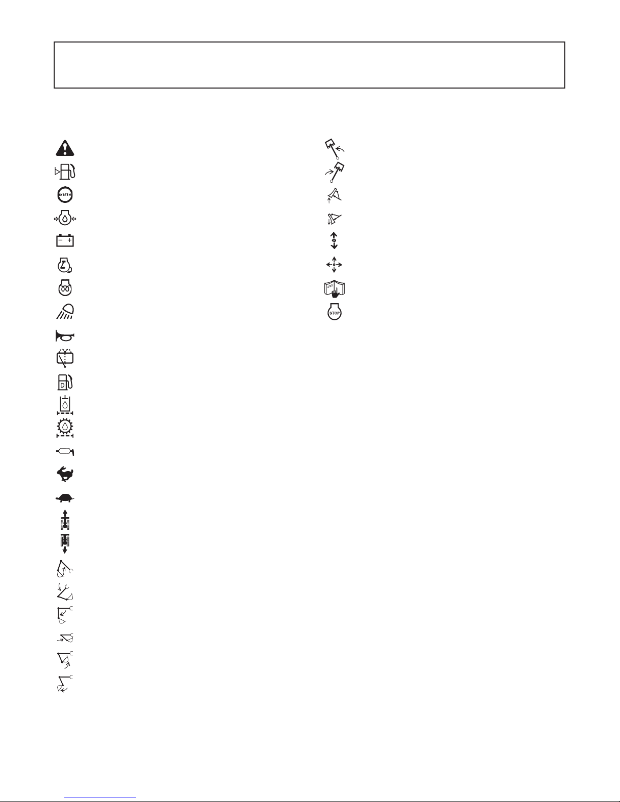
GENERAL SYMBOLS
The instruments and operation elements have been marked with a series of symbols in order to simplify the operation of
excavator. These symbols are listed below with the respective descriptions.
Safety alert Symbol
Warning lamp ''Fuel level too low''
System lamp
Warning lamp ''Engine Oil pressure''
Warning lamp ''Battery charge''
Warning lamp ''Auto Idle (AI) Lamp''
Indicator lamp ''Glow''
Working light switch
Horn
Wiper/Washer switch
Diesel
Hydraulic fluid
Gear oil
Boom swing (left)
Boom swing (Right)
Dozer raise
Dozer lower
Operation direction of control lever
Operation direction of control lever
Read operator's manual
Engine stop control lamp
Grease
Fast
Slow
Excavator - Overhead movement toward the front
Excavator - Overhead movement toward the rear
Boom up
Boom down
Arm up
Arm crowd
Bucket crowd
Bucket dump

FOREWORD
You are now the proud owner of a KUBOTA Excavator. This excavator is a product
of KUBOTA quality engineering and manufacturing. It is made of fine materials and
under a rigid quality control system. It will give you long, satisfactory service. To
obtain the best use of your excavator, please read this manual carefully. It will help
you become familiar with the operation of the excavator and contains many helpful
hints about excavator maintenance. It is KUBOTA's policy to utilize as quickly as
possible every advance in our research. The immediate use of new techniques in
the manufacture of products may cause some small parts of this manual to be
outdated. KUBOTA distributors and dealers will have the most up-to-date
information. Please do not hesitate to consult with them.
Please note that there may be some differences between your actual machine and
the illustration in the instructions.
3
This symbol, the industry's ''Safety Alert Symbol'', is used throughout this manual
and on labels on the machine itself to warn of the possibility of personal injury.
Read these instructions carefully. It is essential that you read the instructions and
safety regulations before you attempt to assemble or use this unit.
3
3
3
IMPORTANT :
NOTE :
DANGER :
WARNING :
CAUTION :
Indicates an imminently hazardous situation which, if not
avoided, will result in death or serious injury.
Indicates a potentially hazardous situation which, if not
avoided, could result in death or serious injury.
Indicates a potentially hazardous situation which, if not
avoided, may result in minor or moderate injury.
Indicates that equipment or property damage could result if
instructions are not followed.
Gives helpful information.
SAFETY FIRST

CONTENTS
SAFE OPERATION ................................................................................................. 1
DEALER SERVICE...................................................................................................... 1
TECHNICAL DATA...................................................................................................... 2
DESCRIPTION OF MACHINE PARTS........................................................................ 3
INSTRUMENT PANEL AND CONTROL ELEMENTS................................................. 4
CHECKS BEFORE START ......................................................................................... 6
DAILY CHECKS....................................................................................................... 6
CAB TYPE MACHINES ........................................................................................... 6
Wiper/Washer Switch(CAB type only) ..............................................................................6
Interior Lamp(CAB type only) ...........................................................................................6
Heater Switch(CAB type).................................................................................................. 7
Opening/Closing of CAB Door(CAB type only)................................................................. 8
Opening/Closing of Front CAB Window(CAB type only) .................................................. 8
Working Light Switch ........................................................................................................9
Emergency Hammer(CAB type only)................................................................................9
OPERATION OF THE ENGINE................................................................................. 10
STARTING THE ENGINE ...................................................................................... 10
Display Selector Switch ..................................................................................................11
Charge Lamp..................................................................................................................12
Oil Lamp ......................................................................................................................... 12
Glow Lamp......................................................................................................................12
LCD Display for Normal Operation ................................................................................. 12
LCD Display for Warning ................................................................................................13
Warning Lamp ................................................................................................................14
Checkpoints after Starting the Engine ............................................................................ 14
STARTING THE ENGINE UNDER COLD CONDITIONS...................................... 15
STOPPING THE ENGINE...................................................................................... 15
Emergency Engine Stop Knob........................................................................................15
STARTING WITH AN AUXILIARY BATTERY ....................................................... 16
Observe Following Guidelines when Starting with an Auxiliary Battery..........................16
EXCAVATOR OPERATION ...................................................................................... 17
RUNNING-IN OF THE NEW EXCAVATOR........................................................... 17
Do not Work with Full Engine Rpm's or Full Loads during the First 50 Working Hours.. 17
Oil Change in the Run-in Stage......................................................................................17
Seat Belt .........................................................................................................................17
STARTING ............................................................................................................. 17
Operator's Seat...............................................................................................................17
Lock Lever ......................................................................................................................18
Working Light Switch ......................................................................................................19
Travel Buzzer..................................................................................................................19
DRIVING ................................................................................................................ 19
Drive Levers(Right,Left)..................................................................................................20
Travel Speed Switch.......................................................................................................21

CONTENTS
TURNS................................................................................................................... 22
Pivot Turn ....................................................................................................................... 22
Spin Turn ........................................................................................................................23
UP AND DOWNHILL DRIVING.............................................................................. 23
OPERATION OF THE DOZER .............................................................................. 24
TWO PATTERN SELECTION SYSTEM(TPSS) .................................................... 24
Pattern Change...............................................................................................................24
OPERATION OF THE BOOM................................................................................ 25
OPERATION OF THE ARM................................................................................... 26
OPERATION OF THE BUCKET ............................................................................ 26
UNIT SWING AND BOOM SWING OPERATION.................................................. 27
Unit Swing Operation......................................................................................................27
Boom Swing Operation................................................................................................... 27
SERVICE PORT OPERATION .............................................................................. 28
Service Port Operation ...................................................................................................28
One Way Flow Operation ...............................................................................................32
1-way or 2-way CIRCUIT SELECTION VALVE OPERATION ............................... 33
AUTO IDLE (AI) OPERATION ............................................................................... 34
IMPORTANT INFORMATION ON EXCAVATOR OPERATION ............................ 34
HOW TO RELEASE PRESSURE TRAPPED IN THE HYDRAULIC SYSTEM...... 35
TRANSPORTING THE EXCAVATOR ON A VEHICLE............................................. 36
LIFTING OF THE EXCAVATOR................................................................................ 38
MAINTENANCE......................................................................................................... 40
MAINTENANCE INTERVALS ................................................................................ 40
OPENING AND CLOSING OF PARTS.................................................................. 43
Opening and Closing of the Fuel Tank Cap....................................................................43
Opening/Closing of the Engine Hood .............................................................................43
Opening/Closing of the Side Hood .................................................................................43
Where to store the Tool and the Grease Gun.................................................................44
Where to keep Operators Manual...................................................................................44
DAILY CHECKS..................................................................................................... 45
Checking Coolant Level.................................................................................................. 45
Checking Fuel Level ....................................................................................................... 45
Checking Engine Oil Level..............................................................................................46
Checking Hydraulic Oil Level.......................................................................................... 46
Lubrication Points ........................................................................................................... 47
Checking Radiator and Oil Cooler ..................................................................................48
Checking Washer Liquid(only for CAB type) ..................................................................48
Checking and Cleaning Engine and Electrical Wiring.....................................................48
Washing Whole Machine................................................................................................48
REGULAR CHECKS AND MAINTENANCE WORK ................................................. 49
EVERY 50 SERVICE HOURS ............................................................................... 49
Draining Fuel Tank .........................................................................................................49
Draining Water Separator...............................................................................................49
Battery ............................................................................................................................ 49
Battery Charging.............................................................................................................50
Greasing Swing Bearing Teeth.......................................................................................51
EVERY 200 SERVICE HOURS ............................................................................. 51
Checking Fan Belt Tension.............................................................................................51

CONTENTS
Checking Radiator Hoses and Clamps...........................................................................51
Inspection and Cleaning Air Filter Element.....................................................................52
Air Filter Maintenance..................................................................................................... 53
Greasing Swing Bearing.................................................................................................53
Checking Fuel Line and Intake Air Line .......................................................................... 54
EVERY 250 SERVICE HOURS ............................................................................. 54
Changing Engine Oil(First Engine Oil Change after 50 Service Hours) ......................... 54
EVERY 500 SERVICE HOURS ............................................................................. 55
Replacing Engine Oil Filter(Replace the engine oil filter every 500 hours,
or every 1 year in the case that service hour is less than 500 hours).............................55
Drive unit Oil Change(First Oil Change at 100 hours) .................................................... 55
Replacing Fuel Filter Cartridge.......................................................................................56
Replacing Hydraulic Return Filter Element(first replacement after 250 service hours) .. 56
EVERY 1000 SERVICE HOURS ........................................................................... 57
Hydraulic Oil Check for Machines with Hydraulic Breakers............................................ 57
Hydraulic Oil Change(Including Replacing Suction Filter
and Breather Filter Element in Hydraulic Tank)..............................................................57
Replacing Hydraulic Pilot Filter Element.........................................................................58
EVERY 1000 SERVICE HOURS OR ONCE A YEAR ........................................... 58
Replacing Air Filter Element ........................................................................................... 58
EVERY 1500 SERVICE HOURS ........................................................................... 58
Checking Fuel Injection Nozzle(Injection Pressure) .......................................................58
EVERY 2000 SERVICE HOURS ........................................................................... 58
Changing Front Idler and Track Roller Oil ...................................................................... 58
Checking Alternator and Starter Motor ...........................................................................58
EVERY 3000 SERVICE HOURS ........................................................................... 59
Checking Injection Pump................................................................................................59
ANNUAL SERVICE................................................................................................ 59
Electrical Wiring and Fuses ............................................................................................ 59
BIENNIAL SERVICING .......................................................................................... 59
Replacing of Radiator Hoses..........................................................................................59
Changing Radiator Coolant ............................................................................................59
Replacing Fuel Hose ......................................................................................................60
Replacing Intake Air line.................................................................................................60
OTHER ADJUSTMENTS AND REPLACEMENTS.................................................... 61
PURGING FUEL SYSTEM .................................................................................... 61
ADJUSTMENT OF TRACKS ................................................................................. 61
Rubber Tracks ................................................................................................................61
Special Information when Using Rubber Tracks.............................................................62
Steel Tracks....................................................................................................................62
CHANGING THE BUCKET .................................................................................... 63
FUSES ................................................................................................................... 63
Replacing Fuses.............................................................................................................63
Fuse Capacities and Circuits..........................................................................................63
Auxiliary Electric .............................................................................................................64
Slow Blow Fuse ..............................................................................................................64
TROUBLESHOOTING............................................................................................... 65
KUBOTA I.C.S. NAVIGATION LIST OF MESSAGES ........................................... 67
OPERATION UNDER COLD WEATHER CONDITIONS .......................................... 69

CONTENTS
PREPARATION FOR OPERATION IN COLD WEATHER .................................... 69
PROCEDURE AFTER DONE WORK.................................................................... 69
LONG STORAGE ...................................................................................................... 70
RECOMMENDED OILS............................................................................................. 72
APPENDICES............................................................................................................ 73
MAIN DIMENSIONS .............................................................................................. 73
LIFTING CAPACITY .................................................................................................. 74
1SAFE OPERATION
SAFE OPERATION
The best insurance against accidents is to abide by the
safety regulations.
Read and understand this manual carefully before
operating the excavator.
Every user, however experienced, should carefully read
and understand this manual and those of the attachments
and accessories before taking the excavator into
operation. The owner is obliged to inform the operators of
these instructions in detail.
Keep this manual in the pocket under the seat.
1. Make yourself acquainted with the excavator and be
aware of its limits. Read the operating instructions
carefully before starting the excavator.
2. Obey the danger, warning and caution labels on the
machine.
3. For your safety, ROPS/FOPS (Roll-Over Protective
Structures, Falling Objects Protective Structures.) with
a seat belt is installed by KUBOTA. Always use the
seat belt when the machine is equipped with a ROPS/
FOPS.
Do not modify structural members of ROPS by
welding, drilling, bending, grinding or cutting, as this
may weaken the structure. If any component is
damaged, replace it. Do not attempt repairs. If ROPS
is loosened or removed for any reason, make sure all
parts are reinstalled correctly. Tighten mounting bolts
to proper torque.
4. The seat belt must be inspected regularly and
replaced if damaged.
5. Study control lever pattern A and pattern B. Then
choose the one which is most familiar. Familiarize
yourself with the pattern selected by operation slowly
at low engine speed.
6. Do not operate the excavator while under the influence
of alcohol, medication, controlled substances or while
fatigued.
7. Check the surroundings carefully before using the
excavator or when attachments are being attached.
A Pay attention to the overhead clearance with electric
wires.
A Check for pipes and buried cables before digging.
A Check for hidden holes, hindrances, soft underground,
and overhangs.
1. BEFORE OPERATION
(1) Seat belt
(1) Pattern selector lever (Two Pattern Selection System: TPSS)
SAFE OPERATION2
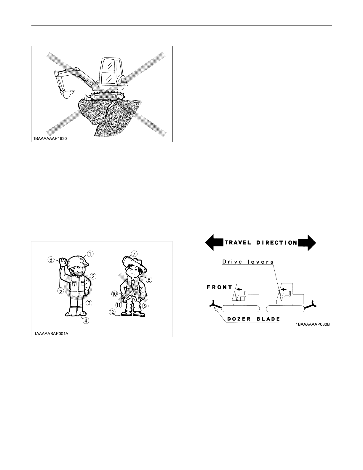
A During excavator use, do not allow any persons within
the working range.
8. Do not allow other persons to use the machine before
having informed him on the exact operation and work
instructions, and be assured that the operator's
manual has been read and completely understood.
9. Do not wear baggy, torn or oversized clothing when
working with the excavator. Clothing can get caught in
rotating parts or control elements which can cause
accidents or injuries. Wear adequate safety clothing,
e.g. safety helmet, safety shoes, eye protection, ear
protection, working gloves, etc., as necessary and as
prescribed by law or statutes.
10.Do not allow passengers to ride on any part of the
excavator at anytime. The operator must remain in the
excavator seat during operation.
11.Check mechanical parts for correct adjustments and
wear. Replace worn or damaged parts immediately.
12.Keep your excavator clean. Heavy soiling, grease,
dust and grass can cause fires, accidents or injuries.
13.Use only KUBOTA authorized attachments.
14.Before starting the excavator, be absolutely sure that
the excavator has been filled with fuel, lubricated,
greased and undergone all necessary maintenance.
15.Do not modify the excavator, otherwise it could lead to
unforeseen safety problems.
16.Make sure attachments, particularly those utilizing
quick attach systems, are securely mounted.
1. Get into and out of the machine safely. Always face the
machine. Always use handrails and available steps
and keep yourself well balanced. Do not hold any of
the control levers and switches. Do not jump on or off
the machine, whether stationary or in motion.
2. Start and control the excavator only from the
operator's seat. The driver should not lean out of his
seat when the engine is running.
3. Before starting the engine, make sure that lock levers
are in position "Lock" and all control levers and pedals
are in their neutral positions and the seat belt is
fastened correctly.
4. Make sure that the dozer blade is in front of you. (The
dozer must be raised.) If the levers are activated with
the dozer blade at the rear, the tracks will move in the
opposite direction of the drive levers.
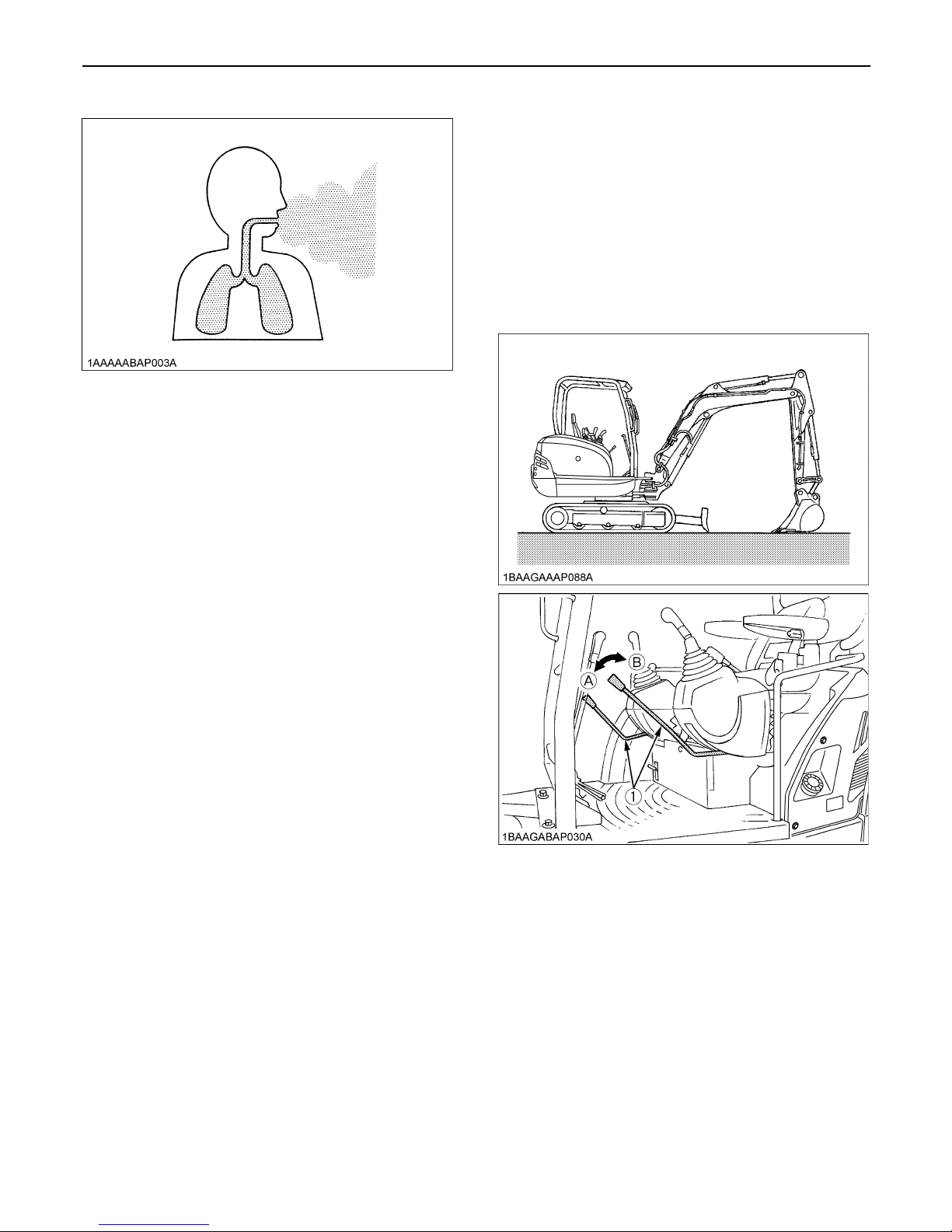
5. Do not operate or idle engine in a non-ventilated area.
Carbon monoxide gas is colorless, odorless, and
deadly.
(1) Helmet
(2) Clothing fit for work
(3) Tight seams
(4) Good grip footwear
(5) Well fitting cuffs
(6) Working gloves
(7) Straw hat
(8) Towel
(9) Baggy trousers
(10) Loose cuffs of the shirt
(11) Baggy shirt
(12) Rubber sandals
2. STARTING OF THE EXCAVATOR
3SAFE OPERATION
6. Keep all safety equipment and covers in place.
Replace damaged or missing safety devices.
7. Precautions against tipping over. Keep away from
steep slopes and embankments. Do not swing the
bucket downhill. Lower the dozer during digging. Keep
the bucket as low as possible while driving uphill. Turn
slowly on slopes (at reduced speed). Do not place the
excavator near the edges of trenches and banks, as
the earth can give away due to the weight of the
excavator.
8. Watch out at all times for the area to which the
excavator is being moved.
Pay attention to any hindrances.
C Safety for children
Tragedy can occur if the operator is not alert to the
presence of children. Children generally are attracted to
machines and the work they do.
1. Never assume that children will remain where you last
saw them.
2. Keep children out of the work area and under the
watchful eye of another responsible adult.
3. Be alert and shut your machine down if children enter
the work area.
4. Never carry children on your machine. There is no safe
place for them to ride. They may fall off and be run
over or interfere with your control of the machine.
5. Never allow children to operate the machine even
under adult supervision.
6. Never allow children to play on the machine or on the
attachments.
7. Use extra caution when backing up. Look behind and
down to make sure the area clear before moving.
8. When parking your machine, if at all possible, park on
a firm, flat and level surface; if not, park across a slope.
Lower the bucket and dozer to the ground, remove the
key, place the control lock levers in the locked position
from the ignition and lock the cab door (if equipped),
before you leave.
Before leaving the machine,
A Park the excavator on a firm, flat and level surface.
A Lower the attachments and the dozer blade to the
ground.
A Stop the engine.
A Release pressure trapped in the hydraulic system.
A Lock all control levers.
A Remove the key.
3. AFTER OPERATION
(1) Lock lever for control lever (A) "Unlock"
(B) "Lock"
SAFE OPERATION4
1. Observe all regulations concerning the transport of
excavators on public roads.
2. Use adequately long and robust ramps when loading
on a vehicle. (for details see "TRANSPORTING THE
EXCAVATOR ON A VEHICLE")
3. Do not change the running direction and to avoid a
tipping over, do not try to swing the attachment
crosswise to the loading ramps.
4. Lower the attachment on the loading plane and
release the pressure from the hydraulic system.
Block the tracks with blocks and tie down the
excavator. After loading the excavator on the vehicle,
securely tie down the undercarriage of the excavator
using suitable chains, tensioners and approved
methods.
5. Avoid abrupt braking of the vehicle with the excavator
loaded. The excavator may shift causing on accident.
6. If the excavator is to tow another machine, make sure
the load is smaller than the strength of the hook, tow
chain or cable.
7. Do not use hooks on the roof of canopy or cabin for
lifting the excavator.
Before doing maintenance work on the excavator, place
the machine on even solid ground, lower the attachments
to the ground, stop the engine , release pressure trapped
in the hydraulic system and remove the key. When
dismantling hydraulic parts, make sure that the hydraulic
oil has cooled down sufficiently to avoid burns.
Start maintenance work carefully, e.g. loosen plug slowly
so that oil will not squirt out.
1. Before doing work on the engine, the exhaust system,
the radiator and the hydraulics, let the excavator cool
down sufficiently.
2. Turn off the engine at all times when filling with fuel.
Avoid spilling and over-filling of fuel.
3. Smoking is prohibited while refueling or handling the
battery! Keep sparks and fire away from the fuel tank
and battery. Flammable gases escape from the
battery, especially during charging.
4. Do not use or charge the refillable type battery if the
fluid level is below the LOWER (lower limit level) mark.
Otherwise, the battery component parts may be
prematurely deteriorated, which may shorten the
battery's service life or cause an explosion. Check the
fluid level regularly and add distilled water as required
so that the fluid level is between the UPPER and
LOWER levels.
5. Read and follow the directions "STARTING WITH AN
AUXILIARY BATTERY" in "OPERATION OF THE
ENGINE", when starting with an auxiliary battery.
6. Keep a first-aid box and a fire extinguisher at hand at
all times.
7. Do not open the radiator cap before the radiator has
cooled down sufficiently
First loosen the cap to the first stop and allow the
system enough time to release the remaining
pressure. Then loosen the cap completely.
8. To avoid short-circuiting the battery, always remove
the ground cable first and attach the plus cable first.
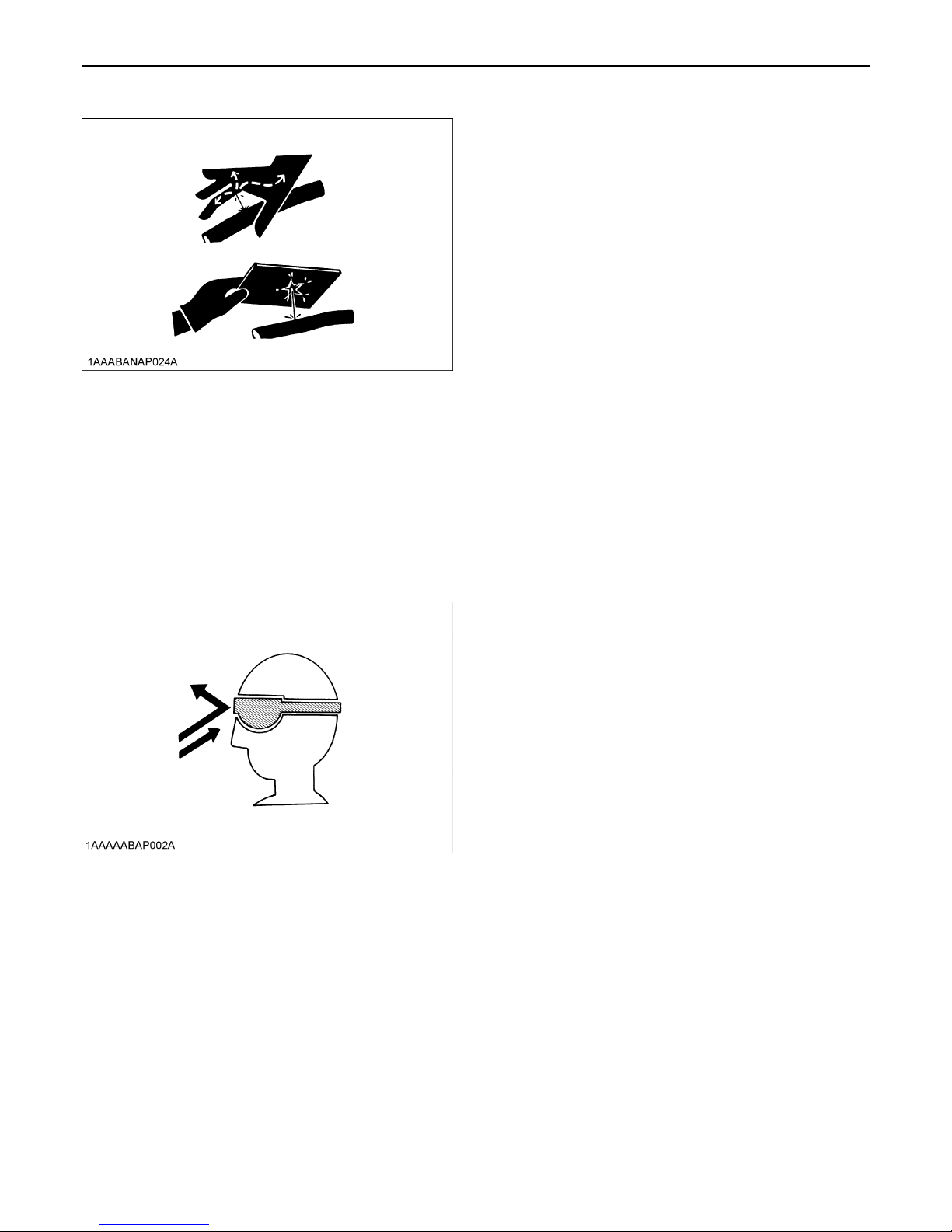
9. Leaking hydraulic fluid has enough pressure to
penetrate the skin and cause serious injuries.
Leakages from pin holes can be totally invisible. Do
not use hands for checking for leaks. Always use a
piece of wood or cardboard. It is strongly
recommended to use a face mask or eye protection.
Should injuries occur with leaking hydraulic fluid,
contact a doctor immediately. This fluid can cause
gangrene or serious allergic reactions.
4. SAFE LOADING AND TRANSPORT OF
THE EXCAVATOR
Max. drawbar pull at
coupling hook
70450 N (7183 kgf)
Max. vertical load at
coupling hook
7210 N (735 kgf)
5. MAINTENANCE
5SAFE OPERATION
10.To avoid environmental damage from acid and heavy
metals, do not throw the battery away.
11.Observe all laws and regulations concerning the
disposal of used oil, coolants, solvents, hydraulic
fluids, battery acids and batteries.
12.To avoid fire, do not heat the hydraulic components
(tanks, pipes, hoses, cylinders) before they have been
drained and washed.
13.Use a face mask or eye protection to protect the eyes
and respiratory system against dust and other foreign
particles.
14.Securely support excavator with stands or suitable
blocking before working underneath. For your safety,
do not work under any hydraulically supported
devices. They can settle, suddenly leak down, or be
accidentally lowered.
15.Do not dismantle the spring of the track tensioner. If
dismantling is necessary, contact your KUBOTA
dealer where the machine was purchased, or
competent service shop. The assembly must be done
according to the work shop manual of KUBOTA
(W.S.M.) for the product involved.
16.KUBOTA uses no parts which are lined with asbestos.
Do not use these kind of parts even if they are
available and can be installed.
SAFE OPERATION6
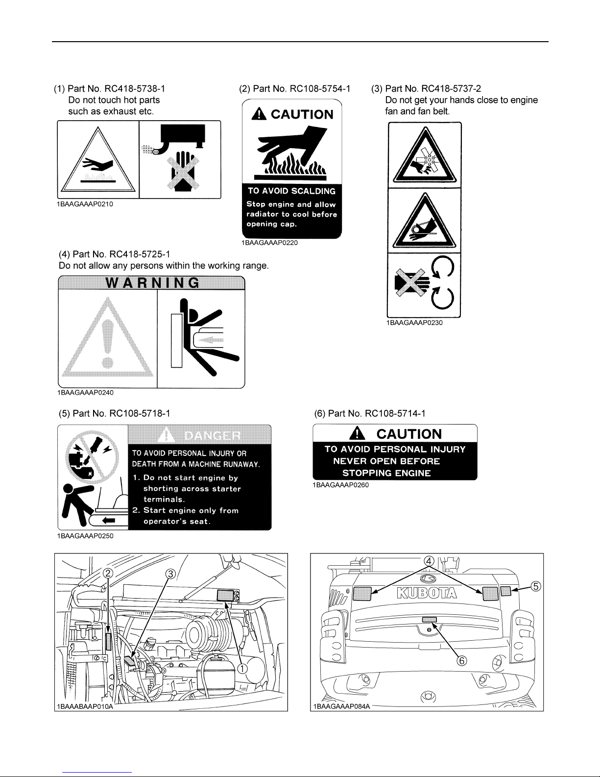
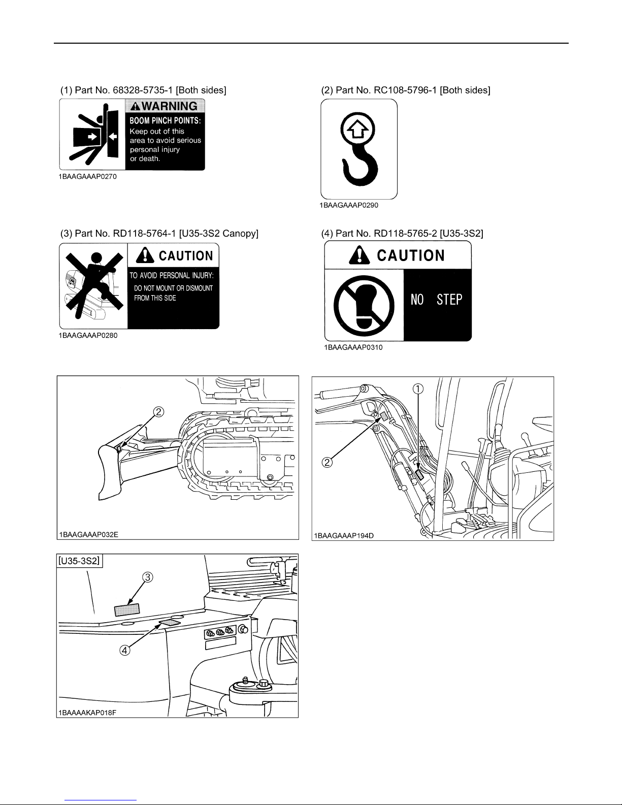
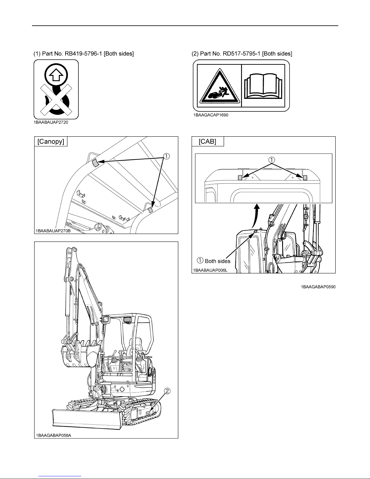
6. DANGER, WARNING AND CAUTION LABELS
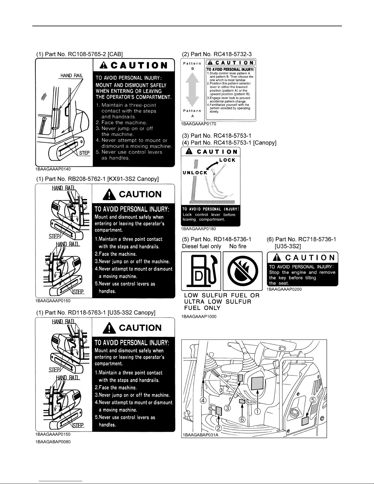
7SAFE OPERATION
SAFE OPERATION8
9SAFE OPERATION
SAFE OPERATION10
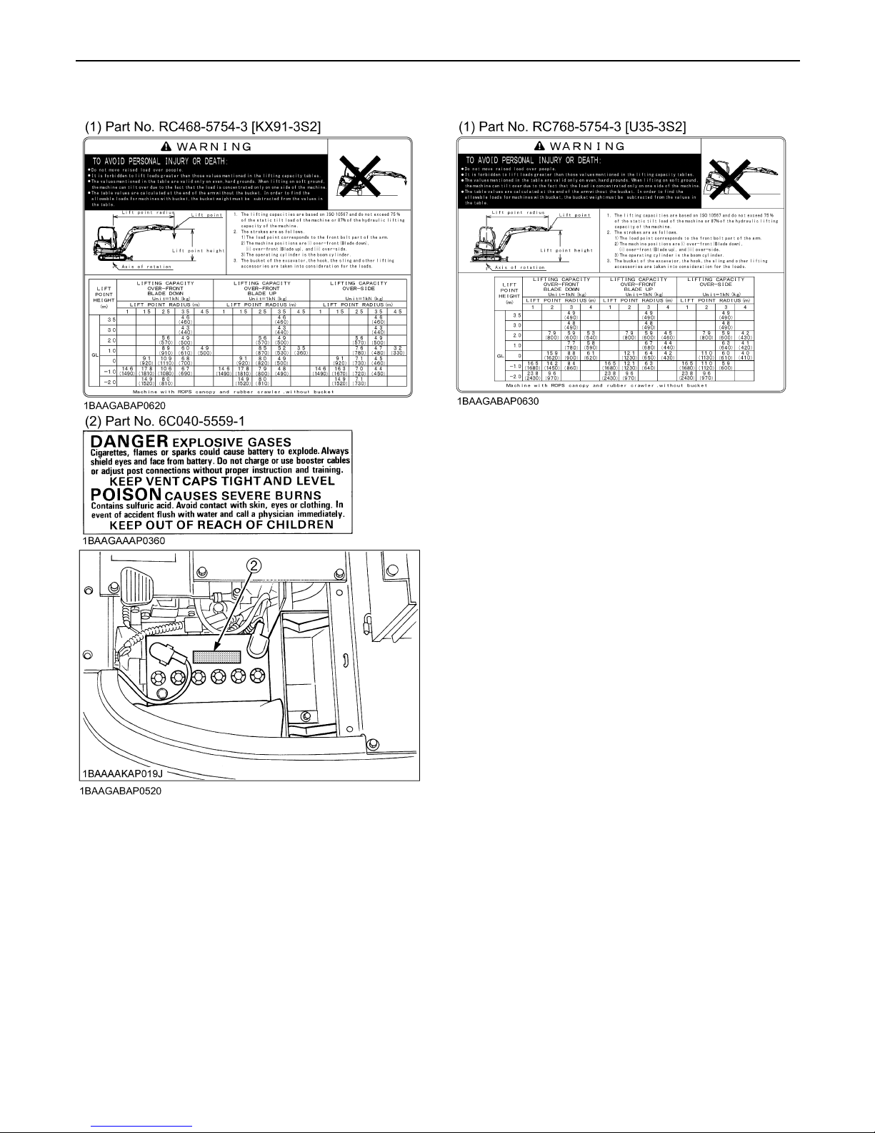
11SAFE OPERATION
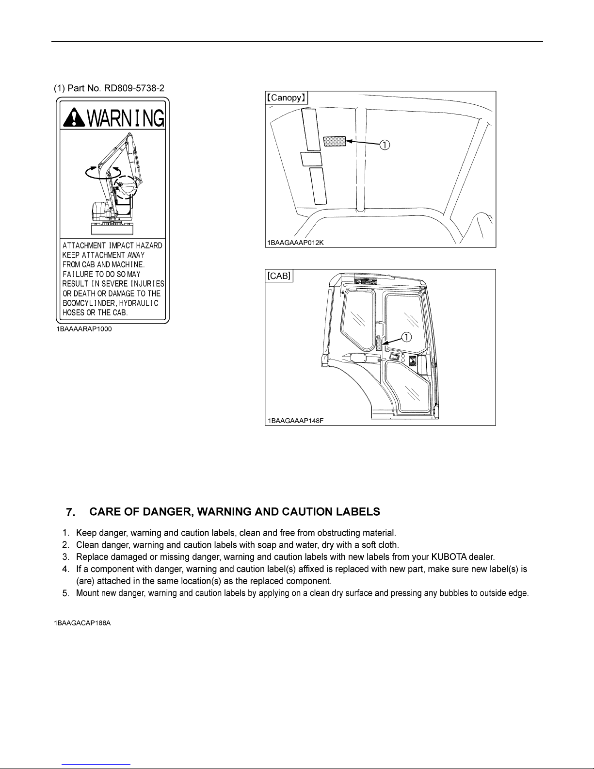
SAFE OPERATION12
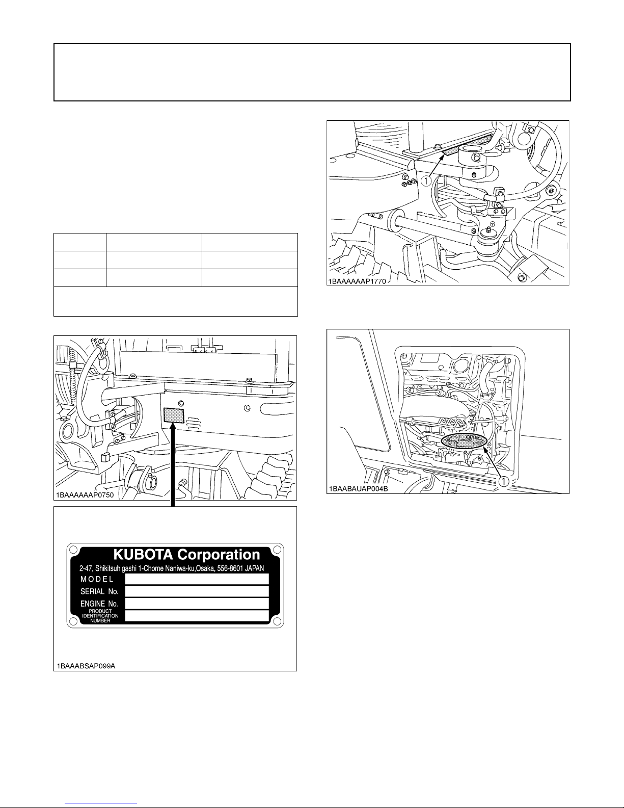
1DEALER SERVICE
DEALER SERVICE
Your KUBOTA dealer is always ready to help so that your
excavator offers the best performance. After having
carefully read these instruction, you will realize that much
of the routine maintenance can be done by yourself. Your
KUBOTA dealer is responsible for servicing and the
delivery of spare parts. When ordering spare parts from
your KUBOTA dealer, always mention the serial number
of the excavator and the engine.
Note these numbers right away in the supplied lines.
Model Serial No.
Excavator
Engine
Dealer's name
(To be filled in through the owner)
(1) Serial No.
(1) Engine serial No.

2 TECHNICAL DATA
TECHNICAL DATA
A Above dimensions are based on the machine with rubber trucks.
A Specifications subject to change without notice.
D With unloaded digging bucket.
D Firm compacted soil.
D Operators must exercise extra caution and follow instructions in the operator's manual.
D Worse condition or heavier attachment to the above will decrease climbing angle.
KUBOTA EXCAVATOR
Model name KX91-3S2 U35-3S2
Type Canopy CAB Canopy CAB
Operating weight (including operator's) kg 3225 3325 3640 3750
Engine
Type Water cooled 4 cycle diesel engine with 3 cylinder
Model name
KUBOTA
D1703-M-E3-BH-US2
KUBOTA
D1703-M-E3-BH-US1
Total displacement cc 1647
Engine power SAE
J1955 gross
kW 22.1
Rated speed rpm 2250
Performance
Unit swing speed rpm 9.4 8.9
Travel speed
Fast km/h 4.8 4.6
Slow km/h 3.1 3.0
Ground pressure
(With operator)
kPa
(kgf/ )
31.8
(0.32)
32.8
(0.33)
32.7
(0.33)
33.7
(0.34)
Climbing angle % (deg) *36 (20)
Angle in case of
crossing slope
% (deg) *27 (15)
Dozer Width x Height mm 1550 x 335 1700 x 335
Boom swing angle
Left rad (deg) 1.40 (80) 1.22 (70)
Right rad (deg) 0.87 (50)
Pressure
connection
for
attachments
Max.displacement
(Theoretical)
L/min 63.0 60.0
Max. pressure
Mpa
(kgf/ )
23.5
(240)
24.5
(250)
Fuel tank capacity L 50 40
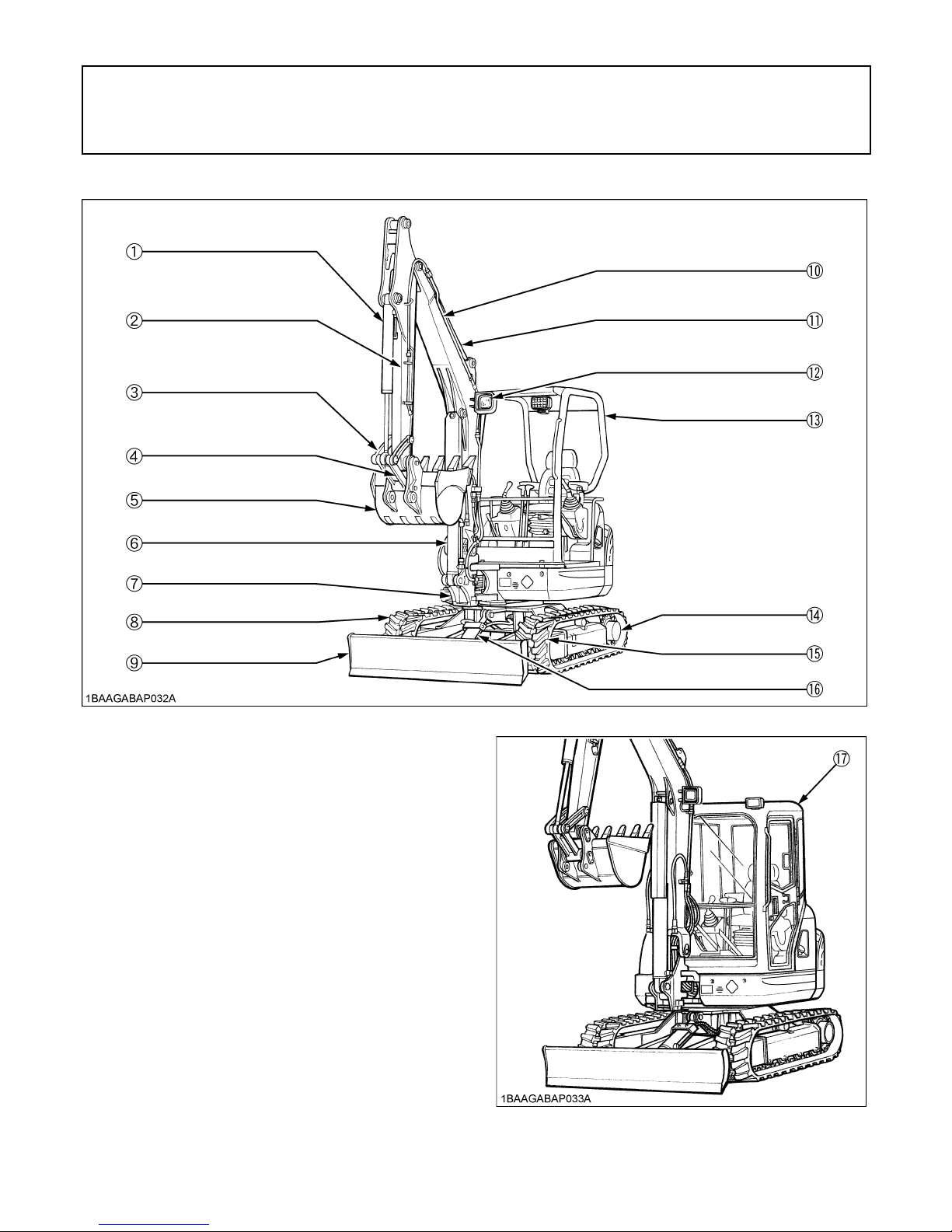
3DESCRIPTION OF MACHINE PARTS
DESCRIPTION OF MACHINE PARTS
DEPICTED CONTENTS
(1) Bucket cylinder
(2) Arm
(3) Bucket link 2 and 3
(4) Bucket link 1
(5) Bucket
(6) Boom cylinder
(7) Swing bracket
(8) Track
(9) Dozer blade
(10) Boom
(11) Arm cylinder
(12) Working light
(13) Canopy
(14) Drive sprocket
(15) Front idler
(16) Dozer cylinder
(17) Cabin

4 INSTRUMENT PANEL AND CONTROL ELEMENTS
INSTRUMENT PANEL AND CONTROL ELEMENTS
B Instrument Panel, Switches
DEPICTED CONTENTS
(1) Cup holder (U35-3S2)
(2) Service port switch
(3) Horn switch
(4) Breaker lock switch
(5) Travel speed switch
(6) Speed indicator light
(7) Starter switch
(8) LCD display
(9) Flow volume setting switch
(10) Switch for Auto idle control
(11) Heater switch (CAB type only)
(12) Emergency engine stop knob
(13) Cup holder (KX91-3S2)
(14) Wiper / Washer switch (CAB type only)
(15) Working Light switch
(16) Service port activation switch
(17) Display selector switch
(18) Warning lamp
5INSTRUMENT PANEL AND CONTROL ELEMENTS
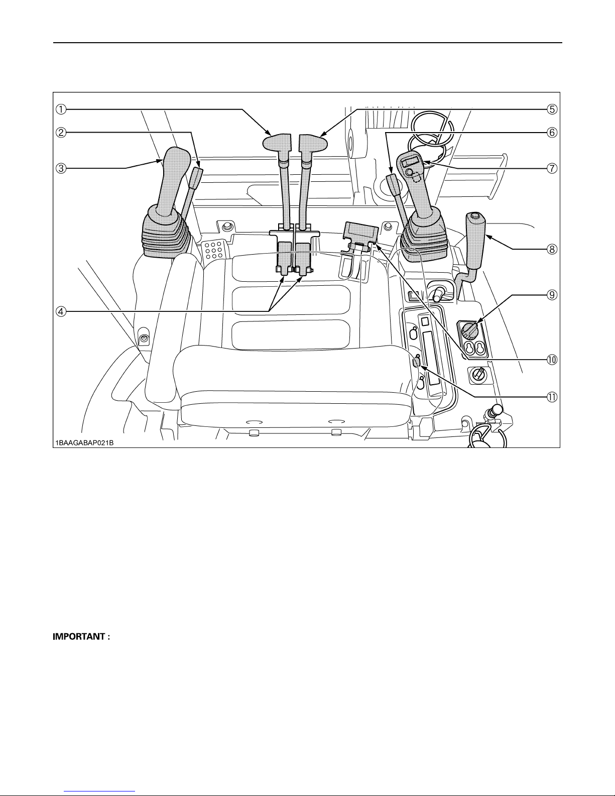
B Control Pedals and Levers
D To prevent inadvertent machine movement, pull the lock lever.
DEPICTED CONTENTS
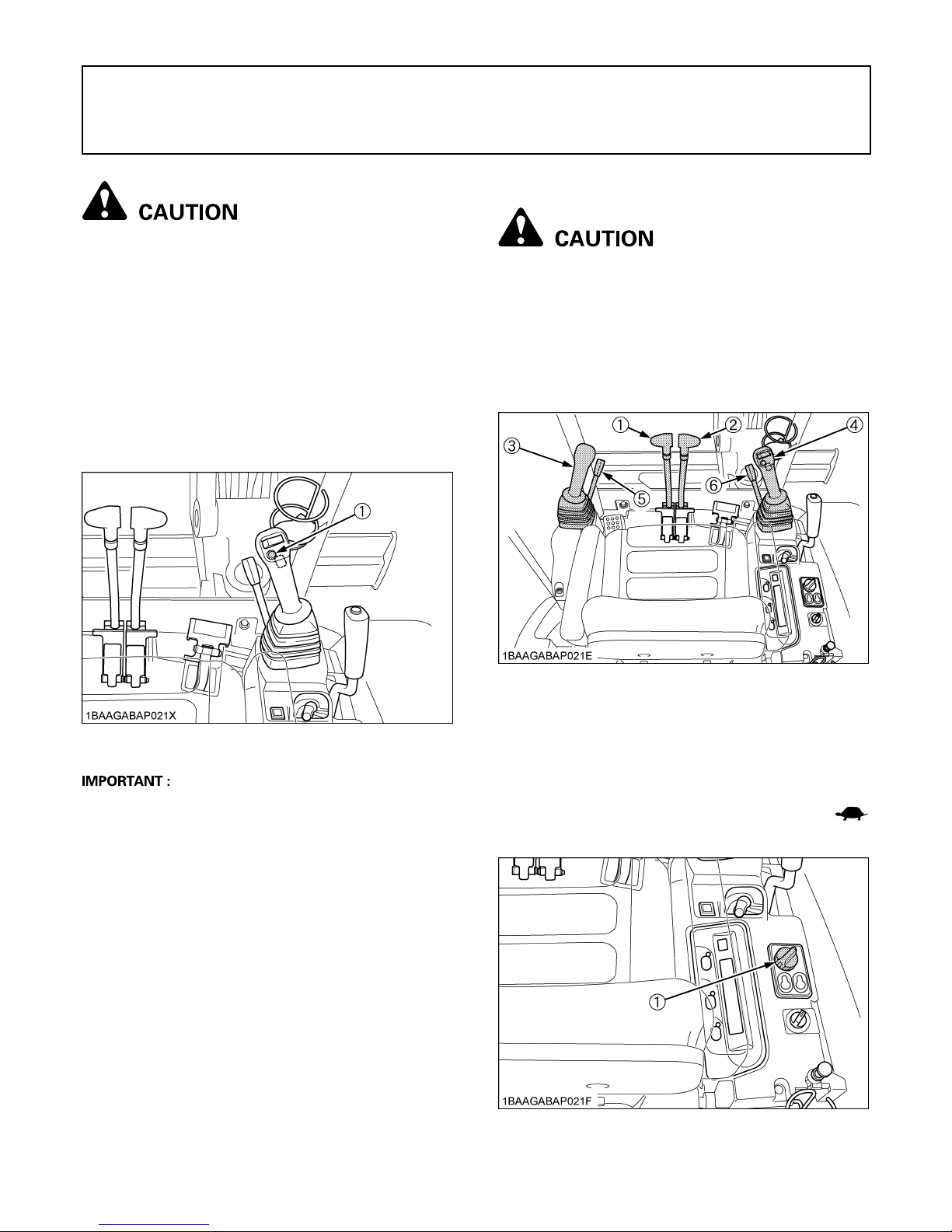
(1) Drive lever (left)
(2) Lock lever (left)*
(3) Control lever for front attachments (left)
(4) Drive pedal
(5) Drive lever (right)
(6) Lock lever (right) [Only Canopy type]*
(7) Control lever for front attachments (right)
(8) Dozer control lever
(9) Throttle potentiometer
(10) Boom swing pedal
(11) Service port activation switch
6 CHECKS BEFORE START
CHECKS BEFORE START
DAILY CHECKS
In order to avoid damage, it is important to check the
condition of the excavator before starting.
To avoid personal injury:
A Do maintenance work on the excavator only on
level ground with the engine off and the lock
lever in the "Lock" position.
Checks
Go around the excavator and check for visual damage
and wear.
Check coolant level. (See regular checkpoints in the
chapter on maintenance.)
Check fuel level.
Check engine oil level.
Check hydraulic fluid level.
Check air filter for clogging.
Check all control lamps, indicators, tachometer and hour
meter.
Check the light system.
Check the seat belt and the ROPS/FOPS safety device.
Check the condition of the safety and warning labels.
(See "DANGER, WARNING AND CAUTION LABELS" in
"SAFE OPERATION".)
CAB TYPE MACHINES
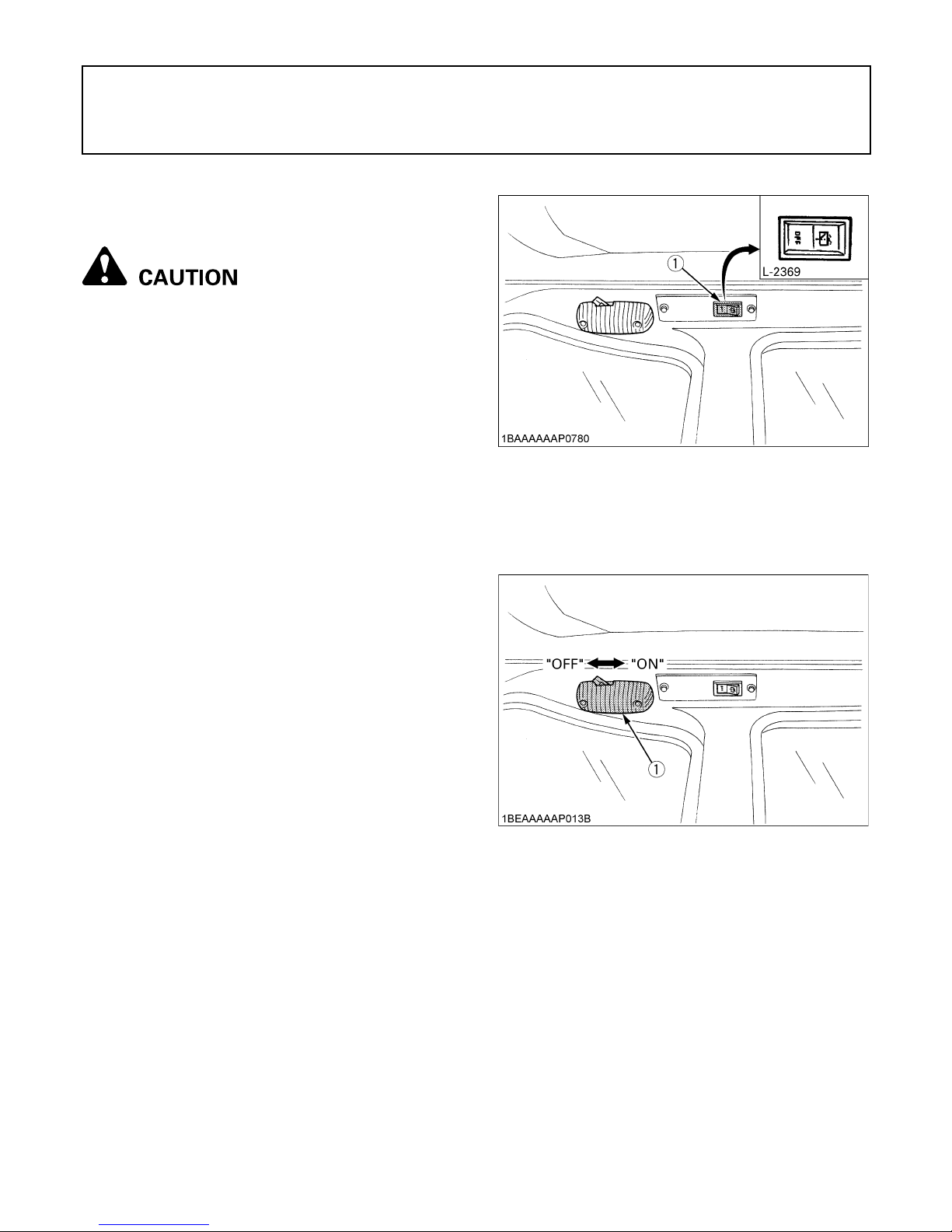
BWiper/Washer Switch(CAB type only)
Turn the starter switch to position "RUN" and push the
switch for the wiper and washer system; the wiper will
begin to move. A further push on the switch will activate
the washer system.
A Do not activate the switch if the tank for the cleaning
fluid is empty; the pump can be damaged.
A This can also be the case if the wiper is moved on a
dry window. In this case, make sure that cleaning fluid
is applied to the pane before activating the wiper.
A In frosty conditions, make sure that the wiper blade is
not frozen to the glass before switching-on. The motor
can be damaged if the wiper system is used under
such conditions.
BInterior Lamp(CAB type only)
To turn on the interior lamp, set the starter switch to the
"RUN" and then the interior lamp switch to the "ON"
positions, respectively.
(1) Wiper switch
(1) Interior lamp
7CHECKS BEFORE START
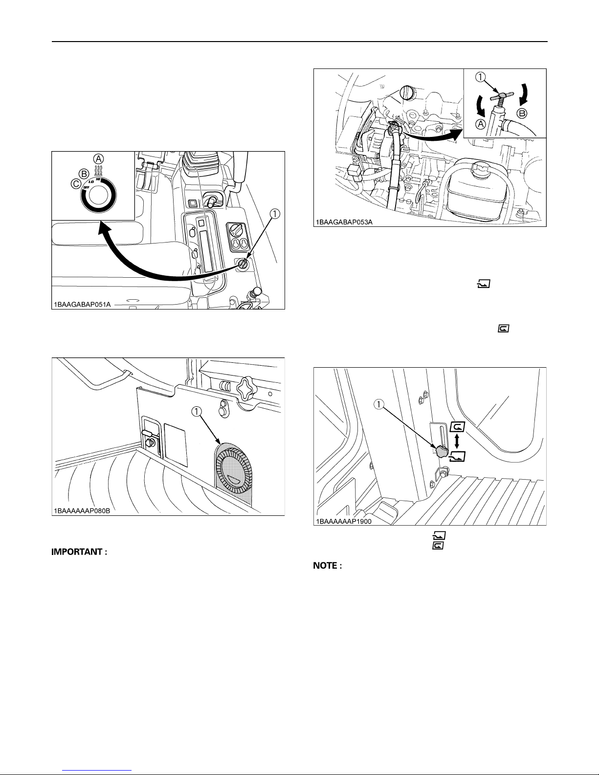
BHeater Switch(CAB type)
Turn the starter switch to position "RUN" and turn the
heater switch clockwise, the heater fan will be activated
and the CAB will start to warm up. The heater has two
positions - "Low" and "High" -.
A During the summer, turn the heater valve clockwise to
close the valve.
C Recirculation / Fresh Air Selection knob
A FRESH AIR: Set the knob to the position, and
fresh air will flow into the CAB. This is helpful when you
work in a dusty conditions or if the glass windows get
foggy.
A RECIRCULATION: Set the knob to the position,
and the in-CAB air will be recirculated.This is useful for
heating the CAB quickly or keeping it extra warm.
A When heating, do not keep the knob at the
"RECIRCULATION" position for a long time. The
windshield easily gets foggy.
A While working in a dusty conditions, keep the knob at
the "FRESH AIR" position. This increases the
pressure in the CAB, which helps prevent dust from
coming into the CAB.
(1) Heater switch (A) Pos. "High"
(B) Pos. "Low"
(C) Pos. "Off"
(1) Heater outlet
(1) Heater valve (A) Open
(B) Close
(1) Recirculation/
fresh air selection knob
"FRESH AIR"
"RECIRCULATION"
CHECKS BEFORE START8
BOpening/Closing of CAB Door(CAB type
only)
1. Unlock the CAB door and pull the knob. Open the CAB
door fully until fixed into place.
2. To close the CAB door, push the release lever down
and close the door.
3. When leaving the excavator, always lock the door.
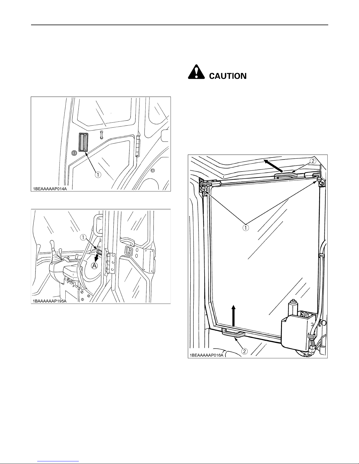
BOpening/Closing of Front CAB
Window(CAB type only)
To avoid personal injury:
A Keep hands and feet away from the area
between front window and CAB frame.
Otherwise the operator risks serious injuries
by pinching or crushing.
A Other persons should stay away when opening
the window.
To open and close the front window, take the steps below.
1. Release the lock levers on the top of the front window.
2. Hold the top and bottom grips tightly with both hands.
Pull the top grip slightly upward and toward yourself to
let the windshield slide inward.
3. Pull the windshield all the way to the rubber at the back
of the CAB. Tighten up the lock levers.
(1) Door knob
(1) Release lever (A) Down
(1) Lock levers (2) Grip
9CHECKS BEFORE START
4. To close the window, take the reverse steps 3, 2 and 1.
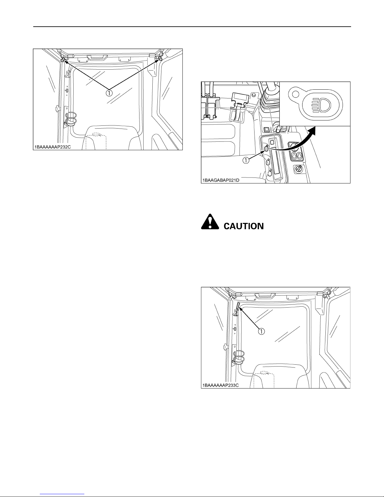
BWorking Light Switch
To turn on the working light, set the starter switch to the
"RUN" position and press the working light switch.
BEmergency Hammer(CAB type only)
To avoid personal injury:
A When breaking the window pane, close your
eyes and cover them with an arm.
Emergency hammer is for breaking window pane to
escape urgently away from excavator as a result of
window rail locking mechanism failure.
(1) Lock lever
(1) Working light switch
(1) Emergency hammer
10 OPERATION OF THE ENGINE
OPERATION OF THE ENGINE
To avoid personal injury:
A Read "SAFE OPERATION" at the beginning of
this operator's manual.
A Obey the danger, warning and caution labels
on the excavator.
A To avoid the danger of exhaust fume
poisoning, do not operate the machine in a
closed building without proper ventilation.
A Always start the engine from the operator's
seat. Do not start the engine while standing
next to the excavator. Before starting the
engine, sound the horn to get the attention of
persons standing nearby.
A Do not use starting fluid or ether.
A In order not to overload the battery and starter, avoid
start-ups of more than 10 sec.
A When engine does not start in 10 sec., please wait 20
sec. or more, before attempting to restart.
STARTING THE ENGINE
To avoid personal injury:
A The operator should not depend solely on the
warning lamps, but should always conduct the
routine checks (see "MAINTENANCE").
Start the engine in the following manner:
1. Before starting the engine, make sure that all control
levers are in the neutral positions.
2. Pull the lock levers all the way back. (lock position)
3. Turn the throttle potentiometer towards the
symbol.
(1) Horn switch
(1) Drive lever (left)
(2) Drive lever (right)
(3) Attachment control lever (left)
(4) Attachment control lever (right)
(5) Lock lever (left)
(6) Lock lever (right) (Only Canopy type)
(1) Throttle potentiometer
 Loading...