

Kubota WSM STV32, WSM STV36, WSM STV40, STV32, STV36 Workshop Manual
...
WORKSHOP MANUAL
KiSC issued 04, 2006 A
TRACTOR
STV32,STV36,STV40

TO THE READER
KiSC issued 04, 2006 A
This Workshop Manual has been prepared to provide servicing personn el with information on the mechanism,
service and main tenance of STV32, STV36 and STV40 . It is divided i nto three parts, "General ", "Mec hanism" an d
"Servicing".
B General
Information on the tracto r identifi catio n, the gene ral precau tions , mainten ance chec k list, c heck and ma intena nce
and special tools are described.
B Mechanism
Information on the construction and function are included. This part should be understood before proceeding with
troubleshooting, disassembling and servicing.
Refer to Diesel Engine / Tractor Mechanism Workshop Manual (Code No. 97897-01872 / 97897-18200) for the one
which has not been described to this workshop manual.
B Servicing
Information on the troubleshooting, servicing specification lists, tightening torque, checking and adjusting,
disassembling and assembling, and servicing which cover procedures, precautions, factory specifications and
allowable limits.
All information illustrations and specifications contained in this manual are based on the latest product information
available at the time of publication.
The right is reserved to make changes in all information at any time without notice.
Due to covering many models of thi s manual, informa tion or picture b eing used ha ve not been specif ied as one
model.
August 2004
KUBOTA Corporation 2004
0000008021E
STV32 · STV36 · STV40, WSM SAFETY INSTRUCTIONS
KiSC issued 04, 2006 A
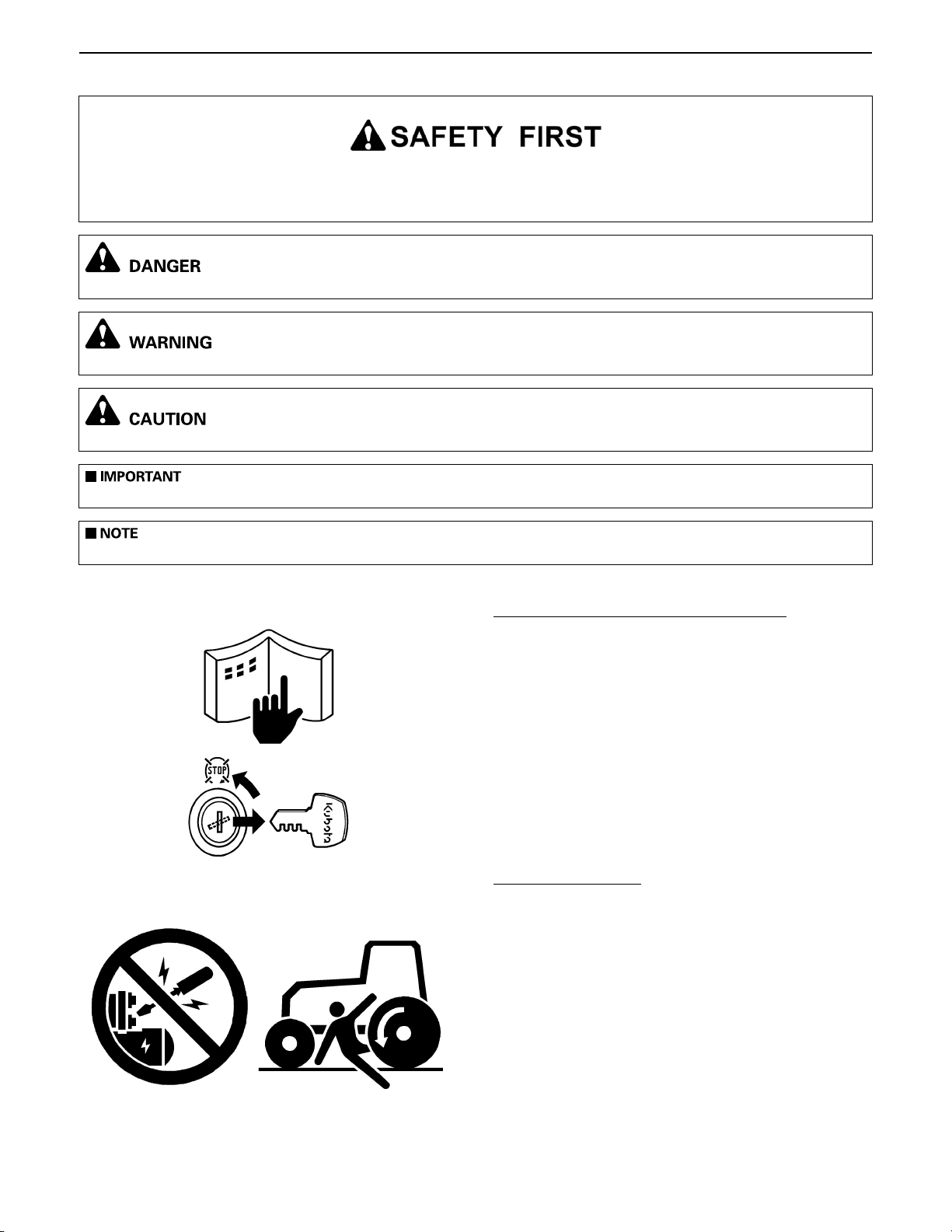
This symbol, the indu stry's "Saf ety Alert Symbol " is used throu ghout this ma nual and on labe ls on the mach ine
itself to warn of the possibility of per sonal injur y. Read these inst ructions care fully.It is essen tial that you read the
instructions and safety regulations before you attempt to repair or use this unit.
A Indicates an imminently hazardous situation which, if not avoided, will result in death or serious injury.
A Indicates a potentially hazardous situation which, if not avoided, could result in death or serious injury.
A Indicates a potentially hazardous situation which, if not avoided, may result in minor or moderate injury.
A Indicates that equipment or property damage could result if instructions are not followed.
A Gives helpful information.
BEFORE SERVICING AND REPAIRING
A Read all instruc tions and safety instructions in this
manual and on your machine safety decal s .
A Clean the work area and machine.
A Park the machine on a firm and level ground, and set
the parking brake.
A Lower the implement to the ground.
A Stop the engine, and remove the key
A Disconnect the battery negative cable
A Hang a "DO NOT OPERATE" tag in operator
station.
SAFETY STARTING
A Do not start the engine by shorting across starter
terminals or bypassing the safety start switch.
A Do not alter or remove any part of machine safety
system.
A Before starting the engine, make sure that all s hift
levers are in neutral positions or in disengaged
positions.
A Never start the engine while standing on ground.
Start the engine only from operator's seat.
0000000752E
0000000753E
0000000754E
1

STV32 · STV36 · STV40, WSM SAFETY INSTRUCTIONS
KiSC issued 04, 2006 A
SAFETY WORKING
A Do not work on the machine while under the
influence of alcohol, medication, or other substances
or while fatigued.
A Wear close fitting clothing and safety equipment
appropriate to the job.
A Use tools appropriate to the wo rk. Makeshift tools,
parts, and procedures are not recommended.
A When servicing is performed together by two or
more persons, take care to perform all work safely.
A Do not work under the machine that is supported
solely by a jack. Always support the machine by
safety stands.
A Do not touch the rotating or hot parts while the
engine is running.
A Never remove the radiator cap while the e ngine is
running, or immediately after stopping. Otherwise,
hot water will spout out from radiator. Only remove
radiator cap when cool enough to touch with bare
hands. Slowly loos en the cap to fi rst stop to re lieve
pressure be fore removing completely.
A Escaping fluid (fue l or hydraulic oil ) under pressure
can penetrate the skin causing serious injury.
Relieve pressure before disconnect ing hydraulic or
fuel lines. Tighten all connections before applying
pressure.
0000000755E
AVOID FIRES
A Fuel is extremely flammable and explosive under
certain condit ions. Do not smoke or al low fla mes or
sparks in your working area.
A To avoid sparks from an accidental short circuit,
always disconnect the battery negative cable first
and connect it last.
A Battery gas can explode. Keep sparks and open
flame away from the top of bat tery, esp ecially when
charging the battery.
A Make sure that no fuel has been spilled on the
engine.
0000000756E
2
STV32 · STV36 · STV40, WSM SAFETY INSTRUCTIONS
KiSC issued 04, 2006 A
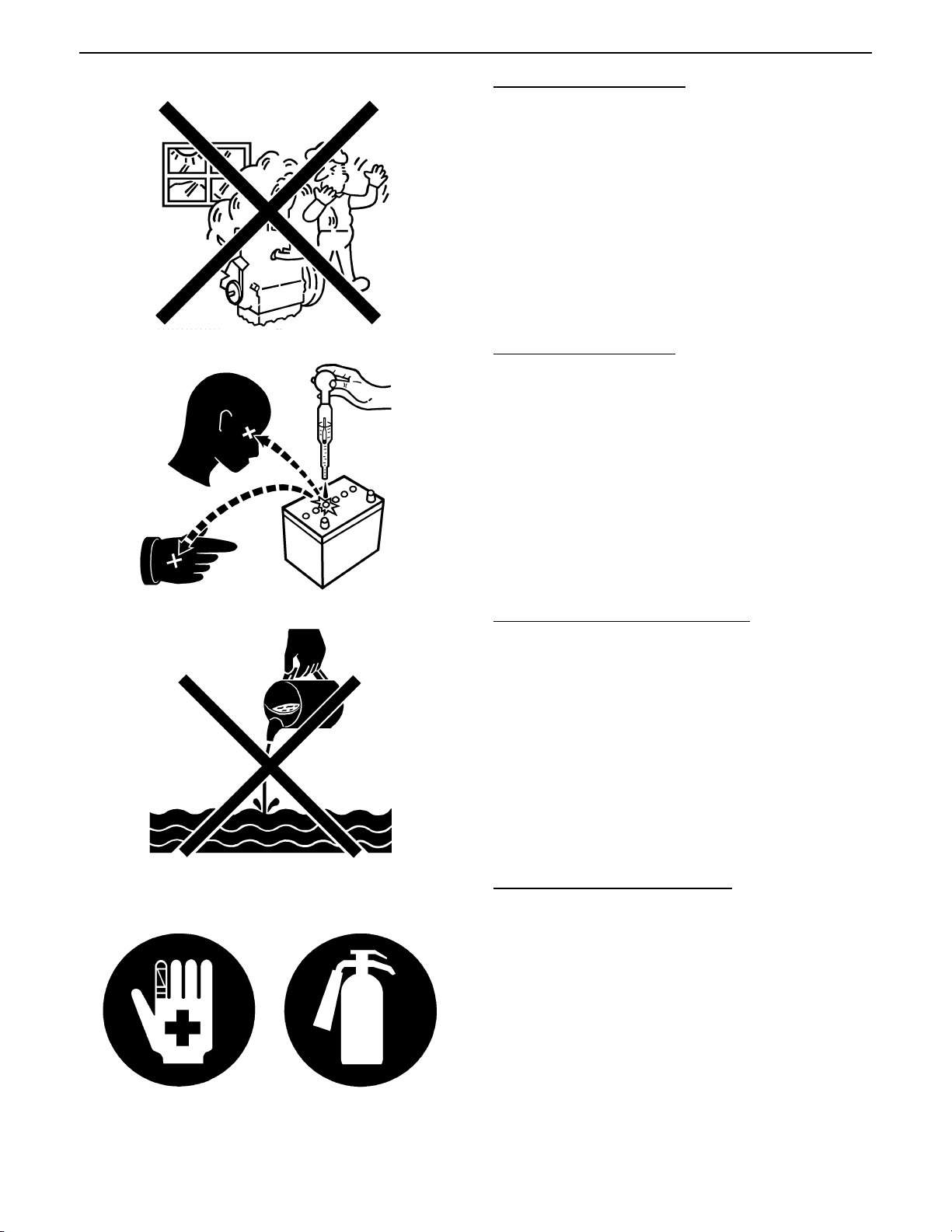
VENTILATE WORK AREA
A If the engine must be running to do some work, make
sure the area is well ventilated. Never run the engine
in a closed area. The exhaust gas contains
poisonous carbon monoxide.
0000000757E
PREVENT ACID BURNS
A Sulfuric acid in battery elec trolyte is poiso nous. It is
strong enough to burn skin, clothing and cause
blindness if splashed into eyes. Keep electrolyte
away from eyes, hands and clothing. If you spill
electrolyte on yourself, flush with water, and get
medical attention immediately.
0000000758E
DISPOSE OF FLUIDS PROPERLY
A Do not pour fluids in to the ground, down a drain, or
into a stream, pond, or lake. Observe relevant
environmental protection regulations when
disposing of oil, fuel, cool ant, electrolyte and other
harmful waste.
0000000759E
PREPARE FOR EMERGENCIES
A Keep a first aid k it and fire ex tingu isher h andy at all
times.
A Keep emergency numbers for doctors, ambulance
service, hospital and fire department near your
telephone.
0000000760E
3
STV32 · STV36 · STV40, WSM SAFETY INSTRUCTIONS
KiSC issued 04, 2006 A
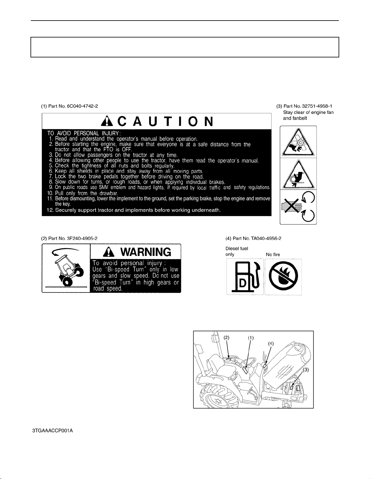
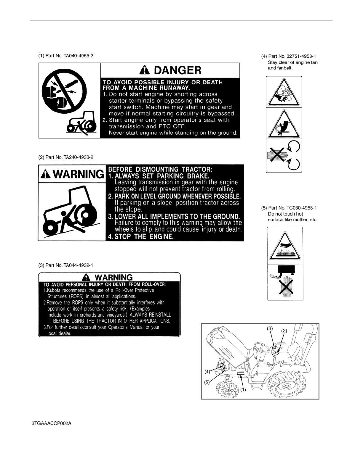
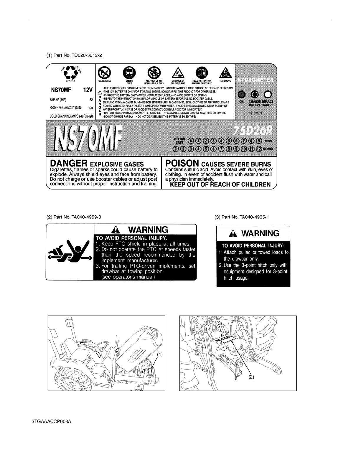
SAFETY DECALS
The following safety decals are installed on the machine.
If a decal becomes damaged, illegible or is not on the machine, replace it. The decal part number is listed
in the parts list.
0000006792E
4
STV32 · STV36 · STV40, WSM SAFETY INSTRUCTIONS
KiSC issued 04, 2006 A
0000006766E
5
STV32 · STV36 · STV40, WSM SAFETY INSTRUCTIONS
KiSC issued 04, 2006 A
0000000762E
6
STV32 · STV36 · STV40, WSM SPECIFICATIONS
KiSC issued 04, 2006 A
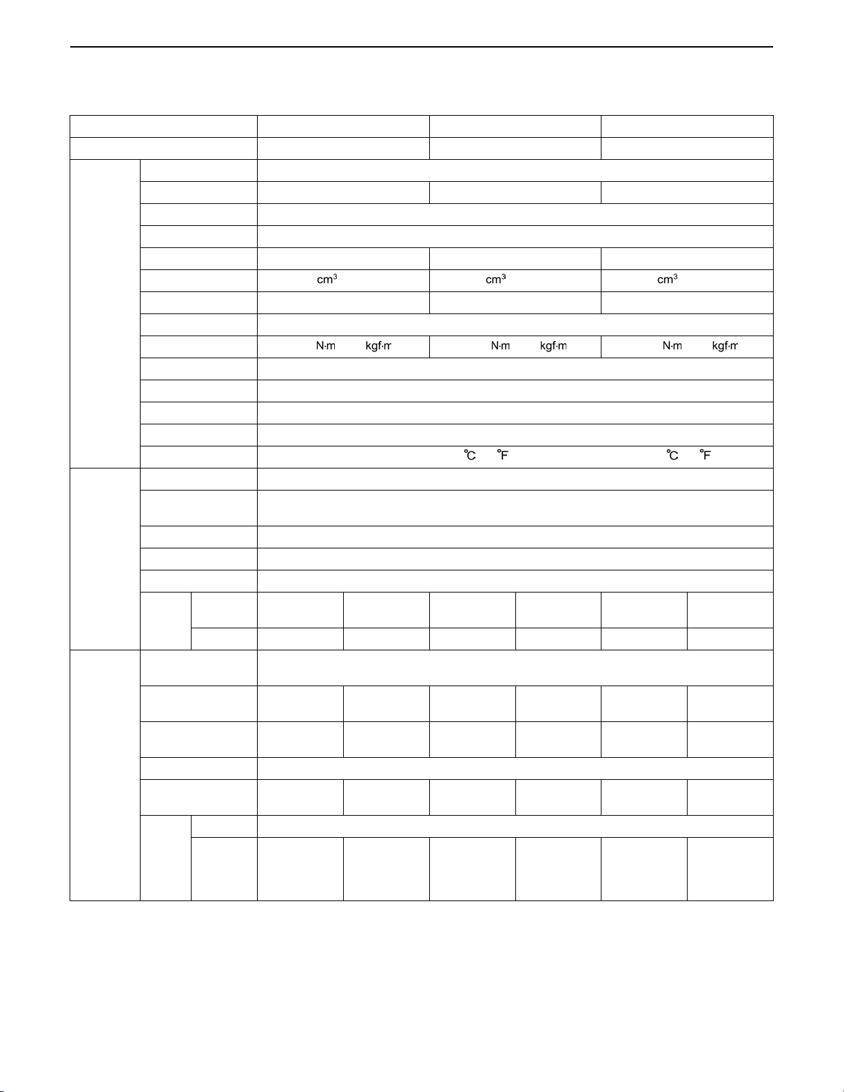
SPECIFICATIONS
Model STV32 STV36 STV40
PTO power 17.7 kW (24.1 HP)* 20.2 kW (27.5 HP)* 22.8 kW (31.0 HP)
Maker KUBOTA
Model D1503-M D1703-M D1803-M
Type E-TVCS, water-cooled, 4-cycle diesel
Number of cylinders 3
Bore and stroke 83 x 92.4 mm (3.27 x 3.64 in.) 87 x 92.4 mm (3.43 x 3.64 in.) 87 x 102.4 mm (3.43 x 4.03 in.)
Total displacement 1499 (91.5 cu.in.) 1647 (100.5 cu.in.) 1826 (111.4 cu.in.)
Engine
Capacities
Dimensions
Engine gross power 24.1 kW (32.3 HP)* 26.8 kW (35.9 HP)* 29.5 kW (39.5 HP)*
Rated revolution 2700 rpm
Maximum torque 99.2 (10.0 ) 108.3 (10.9 ) 120.7 (12.2 )
Battery 12 V, RC : 123 min, CCA : 490 A
Starting system Electric starting with cell starter 12 V, 1.4 kW
Lubricating system Forced Iubrication by trochoidal pump
Cooling system Pressurized radiator, forced circulation with water pump
Fuel Diesel fuel No. 2-D [above -10 (14 )], Diesel fuel No. 1-D [below 10 (14 )]
Fuel tank 29.5 L (7.79 U.S.gals, 6.49 Imp.gals)
Engine crankcase
(with filter)
Engine coolant 6.1 L (6.4 U.S.qts, 5.4 Imp.qts)
Transmission case 22 L (5.81 U.S.gals, 4.84 Imp.gals)
Front axle case 4.0 L (4.2 U.S.qts, 3.5 Imp.qts)
Tires
Front
Rear 9.5 - 22 13.6 - 16 9.5 - 22 13.6 - 16 9.5 - 22 13.6 - 16
Overall length
(with 3P)
Overall width
(min. tread)
Overall height
(with ROPS)
Wheel base 1610 mm (63.4 in.)
Minimum ground
clearance
Front 1030 mm (40.6 in.)
Tread
Rear
Farm:
6 - 12
1220 mm
(48.0 in.)
2350 mm
(92.5 in.)
235 mm
(9.3 in.)
950 mm
(37.4 in.)
1070 mm
(42.1 in.)
Turf:
24 x 8.5 - 14
1310 mm
(51.6 in.)
2340 mm
(92.1 in.)
225 mm
(18.9 in.)
965 mm
(38.0 in.)
1055 mm
(41.5 in.)
6.7 L (7.1 U.S.qts, 5.9 Imp.qts)
Farm:
6 - 12
2860 mm (112.6 in.)
1220 mm
(48.0 in.)
2350 mm
(92.5 in.)
235 mm
(9.3 in.)
950 mm
(37.4 in.)
1070 mm
(42.1 in.)
Turf:
24 x 8.5 - 14
1310 mm
(51.6 in.)
2340 mm
(92.1 in.)
225 mm
(18.9 in.)
965 mm
(38.0 in.)
1055 mm
(41.5 in.)
Farm:
6 - 12
1220 mm
(48.0 in.)
2350 mm
(92.5 in.)
235 mm
(9.3 in.)
950 mm
(37.4 in.)
1070 mm
(42.1 in.)
Turf:
24 x 8.5 - 14
1310 mm
(51.6 in.)
2340 mm
(92.1 in.)
225 mm
(18.9 in.)
965 mm
(38.0 in.)
1055 mm
(41.5 in.)
7

STV32 · STV36 · STV40, WSM SPECIFICATIONS
KiSC issued 04, 2006 A
Model STV32 STV36 STV40
Weight (with ROPS)
Clutch Dry single plate
Steering Hydrostatic power steering
Travelling
system
Hydraulic
system
PTO
system
Transmission Main-hydrostatic transmission, range gear shift (3 forward and 3 reverse)
Brake Wet disk type
Min. turning radius
(with bi-speed turn)
Differential Bevel gear
Hydraulic control
system
Pump capacity
Three point hitch SAE Category 1
Max. lift
force
Rear
Mid
975 kg
(2150 Ibs)
At lift
points
24 in.
behind lift
points
PTO shaft SAE 1-3/8, 6 splines
Revolution 2 speeds (540 rpm at 2670 engine rpm, 800 rpm at 2717 engine rpm)
PTO shaft U.S.A. No.5 (KUBOTA 10-tooth) involute spline
Revolution 1 speed (2500 rpm at 2734 engine rpm)
995 kg
(2194 Ibs)
2.2 m (7.2 feet) with brake, 2.5 m (8.2 feet) without brake
3P : 22.3 L / min (5.9 U.S.gals / min, 4.9 Imp.gals min)
Power steering : 13.6 L / min (3.6 U.S.gals / min., 3.0 Imp.gals / min)
975 kg
(2150 Ibs)
Position control
1150 kg (2535 Ibs)
890 kg (1962 Ibs)
995 kg
(2194 Ibs)
975 kg
(2150 Ibs)
995 kg
(2194 Ibs)
Note : * Manufacture's estimate.
The company reserves the right to change the specifications without notice.
0000004797E
8

STV32 · STV36 · STV40, WSM TRAVELLING SPEEDS
KiSC issued 04, 2006 A
TRAVELLING SPEEDS
Model STV32, 36, 40
Tire Size (Rear) 9.5 - 22 13.6 - 16
Range gear shift lever km/h km/h
1 (Low) 0 to 6.6 0 to 6.5
Forward
2 (Middle) 0 to 12.7 0 to 12.6
3 (High) 0 to 28.4 0 to 28.2
Max. Speed (at 2850 engine rpm) 29.9 29.8
1 (Low) 0 to 4.8 0 to 4.7
2 (Middle) 0 to 9.2 0 to 9.2
Reverse
3 (High) 0 to 20.6 0 to 20.4
Max. Speed (at 2850 engine rpm) 21.7 21.6
The company reserves the right to change the specifications without notice
0000008023E
9
STV32 · STV36 · STV40, WSM DIMENSIONS
KiSC issued 04, 2006 A
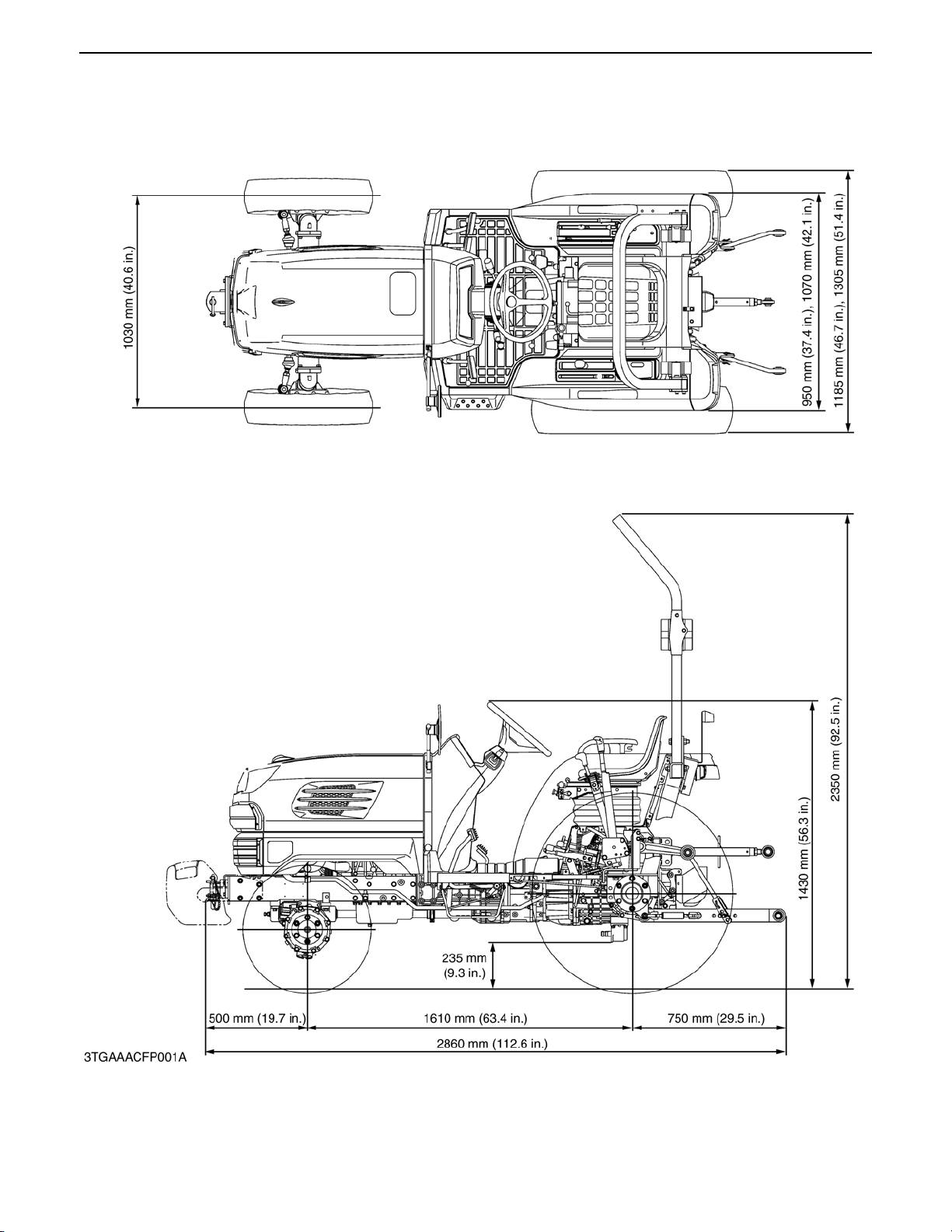
DIMENSIONS
0000006808E
10

KiSC issued 04, 2006 A
G GENERAL

CONTENTS
KiSC issued 04, 2006 A
1. TRACTOR IDENTIFICATION.............................................................................................G-1
2. GENERAL PRECAUTION..................................................................................................G-2
3. HANDLING PRECAUTIONS FOR ELECTRICAL PARTS AND WIRING......................G-3
[1] WIRING..............................................................................................................................G-3
[2] BATTERY ..........................................................................................................................G-5
[3] FUSE .................................................................................................................................G-5
[4] CONNECTOR....................................................................................................................G-6
[5] HANDLING OF CIRCUIT TESTER.................................................................................G-7
4. LUBRICANTS, FUEL AND COOLANT.............................................................................G-8
5. TIGHTENING TORQUES...................................................................................................G-9
[1] GENERAL USE SCREWS, BOLTS AND NUTS ..........................................................G-9
[2] STUD BOLTS ...................................................................................................................G-9
6. MAINTENANCE CHECK LIST ........................................................................................G-10
7. CHECK AND MAINTENANCE ........................................................................................G-12
[1] DAILY CHECK............................ ..... ............................................................. ..................G-12
[2] CHECK POINTS OF INITIAL 50 HOURS...................................................................G-13
[3] CHECK POINTS OF EVERY 50 HOURS...................................................................G-18
[4] CHECK POINTS OF EVERY 100 HOURS.................................................................G-20
[5] CHECK POINTS OF EVERY 200 HOURS.................................................................G-27
[6] CHECK POINTS OF EVERY 400 HOURS.................................................................G-29
[7] CHECK POINTS OF EVERY 600 HOURS.................................................................G-30
[8] CHECK POINTS OF EVERY 800 HOURS.................................................................G-30
[9] CHECK POINTS OF EVERY 1 YEAR........................................................................G-30
[10] CHECK POINTS OF EVERY 2 YEARS......................................................................G-30
[11] OTHERS..........................................................................................................................G-33
8. SPECIAL TOOLS .............................................................................................................G-36
[1] SPECIAL TOOLS FOR ENGINE..................................................................................G-36
[2] SPECIAL TOOLS FOR TRACTOR...............................................................................G-42
9. TIRES ................................................................................................................................G-47
[1] TIRE PRESSURE...........................................................................................................G-47
[2] TREAD.............................................................................................................................G-48
(1) Front Wheels...........................................................................................................G-48
(2) Rear Wheels............................................................................ ................................G-49
[3] TIRE LIQUID INJECTION..............................................................................................G-50
10.IMPLEMENT LIMITATIONS .............................................................................................G-52
STV32 · STV36 · STV40, WSM GENERAL
KiSC issued 04, 2006 A
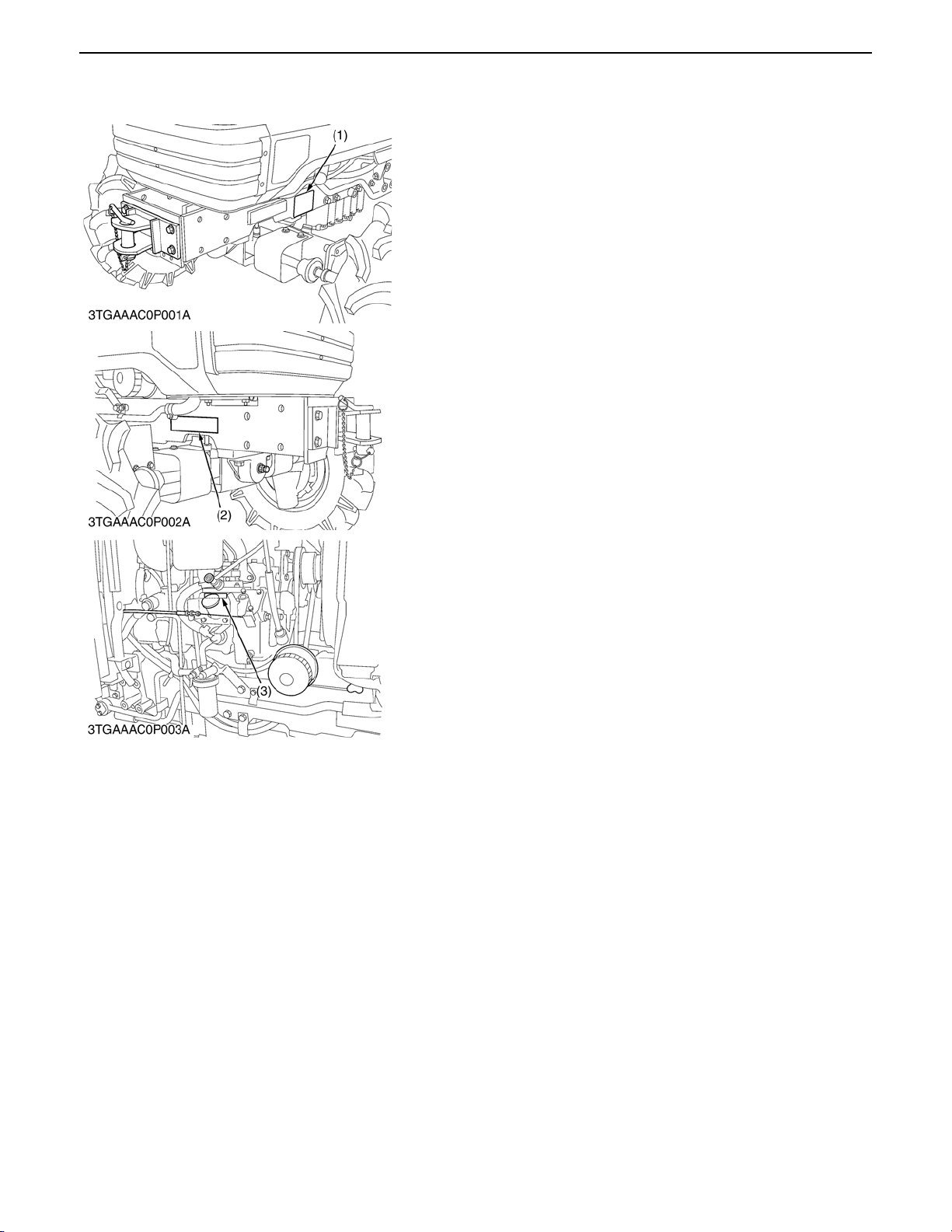
1. TRACTOR IDENTIFICATION
When contacting your local KUBOTA distributor, always specify
engine serial number, tractor serial number and hour meter
reading.
(1) Tractor Identification Plate (3) Engine Serial Number
(2) Tractor Serial Number
0000007957E
G-1
STV32 · STV36 · STV40, WSM GENERAL
KiSC issued 04, 2006 A
2. GENERAL PRECAUTION
A During disassembly, carefully arrange removed parts in a
clean area to prevent conf usion late r. Screws, bolts and nuts
should be installed in their original position to prevent
reassembly errors.
A When special tools are required, use KUBOTA genuine
special tools. Special tools which are not frequently used
should be made according to the drawings provided.
A Before disassembling or servicing electrical wires, always
disconnect the ground cable from the battery first.
A Remove oil and dirt from parts before measuring.
A Use only KUBOTA genuine parts for parts replacement to
maintain machine performance and to assure safety.
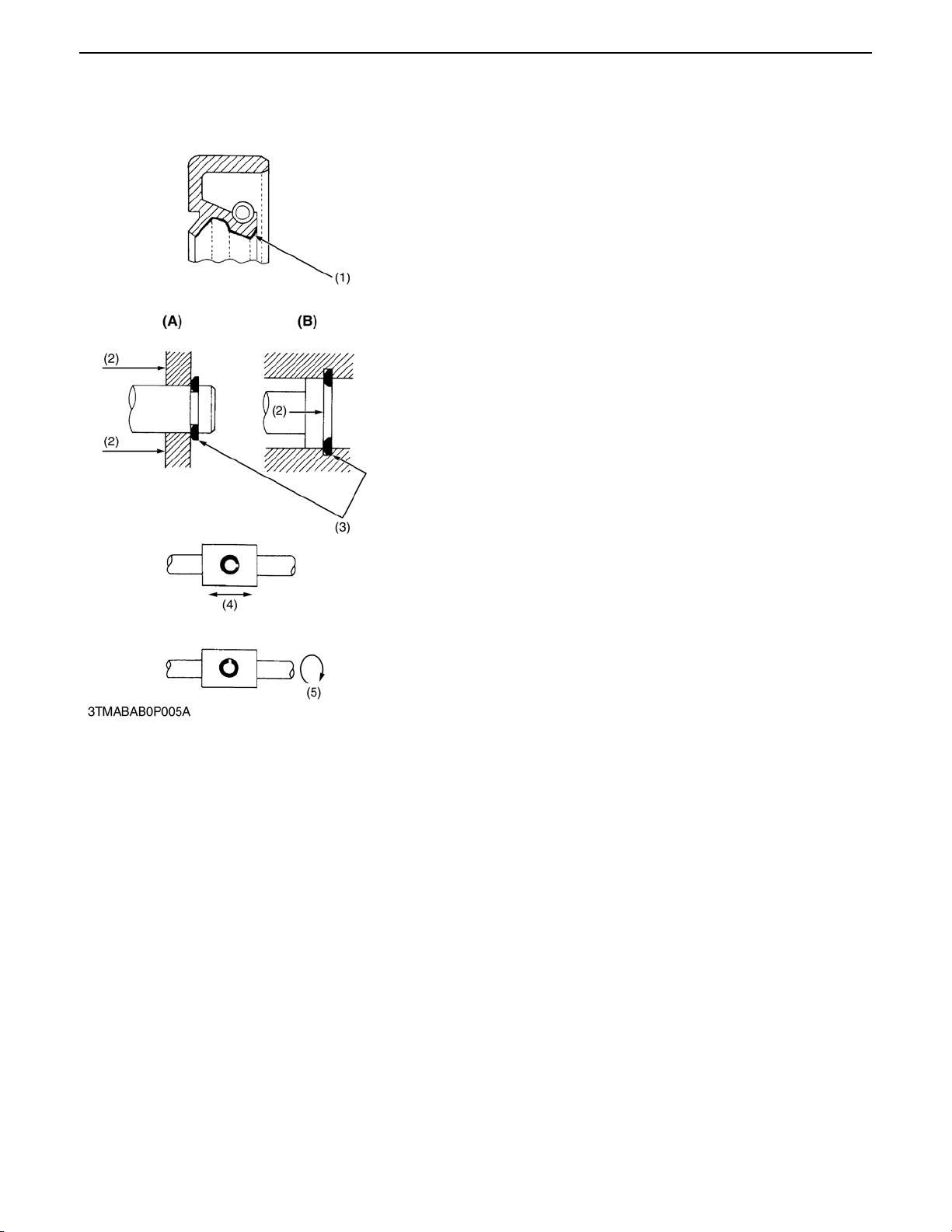
A Gaskets and O-rings must be replaced during reassembly.
Apply grease to new O -rings or oil seals b efore assembling.
See the figure left side.
A When reassembling external snap rings or internal snap rings,
they must be position ed so that sharp edge face s again st the
direction from which a force is applied. See the figure left side.
A When inserting spring pins, their splits must face the direction
from which a force is applied. See the figure left side.
A To prevent damage to t he hydraul ic system, u se only sp ecified
fluid or equivalent.
(1) Grease (A) External Snap Ring
(2) Force (B) Internal Snap Ring
(3) Sharp Edge
(4) Axial Force
(5) Rotating Movement
0000000612E
G-2

STV32 · STV36 · STV40, WSM GENERAL
KiSC issued 04, 2006 A
3. HANDLING PRECAUTIONS FOR ELECTRICAL PARTS
AND WIRING
To ensure safety and prevent damage to the machine and
surrounding equipment, heed the following precautions in
handling electrical parts and wiring.
A Check electrical wiring for damage and loosened
connection every year. To this end, educate the customer
to do his or her own check and at the same time
recommend the dealer to perform periodic check for a fee.
A Do not attempt to modify or remodel any electrical parts
and wiring.
A When removing the battery cables, disconnect the
negative cable first. When installing the battery cables,
connect the positive cable first.
(1) Negative Terminal (2) Positive Terminal
0000000613E
[1] WIRING
A Securely tighten wiring terminals.
(1) Correct (2) Incorrect
(Securely Tighten) (Loosening Leads to Faulty
Contact)
A Do not let wiring contact dangerous part.
(1) Dangerous Part (3) Wiring (Correct)
(2) Wiring (Incorrect) (4) Dangerous Part
A Securely insert grommet.
(1) Grommet (A) Correct
(B) Incorrect
0000000614E
0000000615E
0000000616E
G-3
STV32 · STV36 · STV40, WSM GENERAL
KiSC issued 04, 2006 A
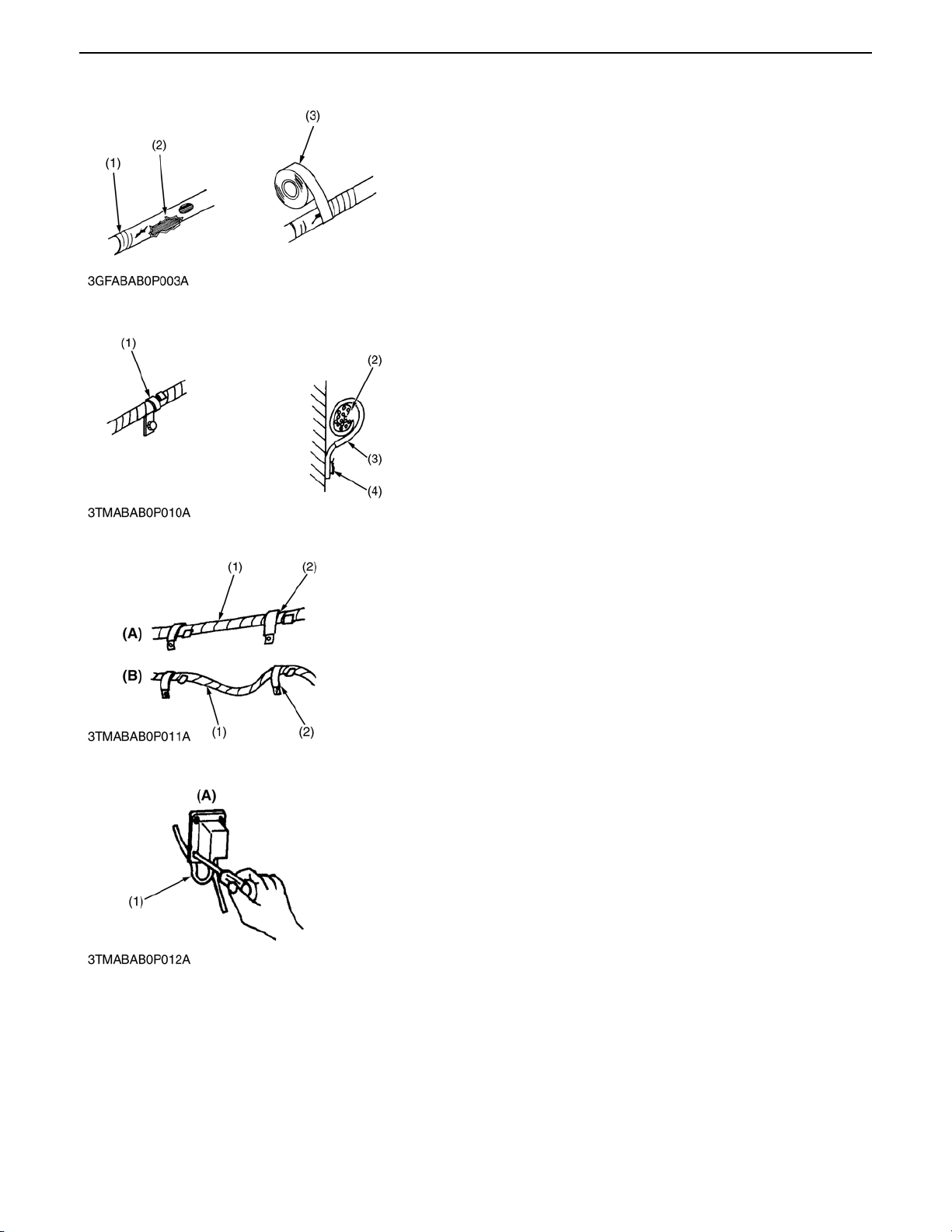
A Repair or change torn or aged wiring immediately.
(1) Aged (3) Insulating Vinyl Tape
(2) Torn
0000002256E
A Securely clamp, being careful not to damage wiring.
(1) Clamp (3) Clamp
*Wind Clamp Spirally (4) Welding Dent
(2) Wire Harness
0000000617E
A Clamp wiring so that there is no twist, unnecessary sag, or
excessive tension, except for movable part, where sag be
required.
(1) Wiring (A) Correct
(2) Clamp (B) Incorrect
0000000618E
A In installing a part, take care not to get wiring caught by it.
(1) Wiring (A) Incorrect
0000000619E
G-4
STV32 · STV36 · STV40, WSM GENERAL
KiSC issued 04, 2006 A
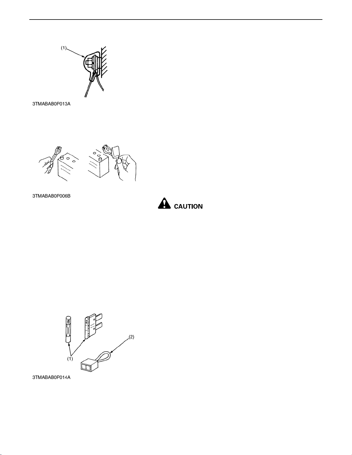
A After installing wiring, check protection of terminals and
clamped condition of wiring, only connect battery.
(1) Cover
*Securely Install Cover
0000000620E
[2] BATTERY
A Take care not to confuse positive and negative terminal posts.
A When removing battery cables, disconnect negative cable
first. When installing battery cables, check for polarity and
connect positive cable first.
A Do not install an y b atte ry wi th ca pac it y o the r than is s pe ci fie d
(Ah).
A After connecting cab les to battery terminal posts, apply high
temperature grease to them and securely install terminal
covers on them.
A Do not allow dirt and dust to collect on battery.
[3] FUSE
A Take care not to let battery liquid spill on your skin and
clothes. If contaminated, wash it off with water
immediately.
A Before recharging the battery, remove it from the
machine.
A Before recharging, remove cell caps.
A Do recharging in a well-ventilated place where there is no
open flame nearby, as hydrogen gas and oxygen are
formed.
0000000621E
A Use fuses with specified capacity.
Neither too large or small capacity fuse is acceptable.
A Never use steel or copper wire in place of fuse.
A Do not install working light, radio set, etc. on machine which is
not provided with reserve powe r suppl y.
A Do not install accessories if fuse capacity of reserve power
supply is exceeded.
(1) Fuse (2) Fusible Link
0000000622E
G-5
STV32 · STV36 · STV40, WSM GENERAL
KiSC issued 04, 2006 A
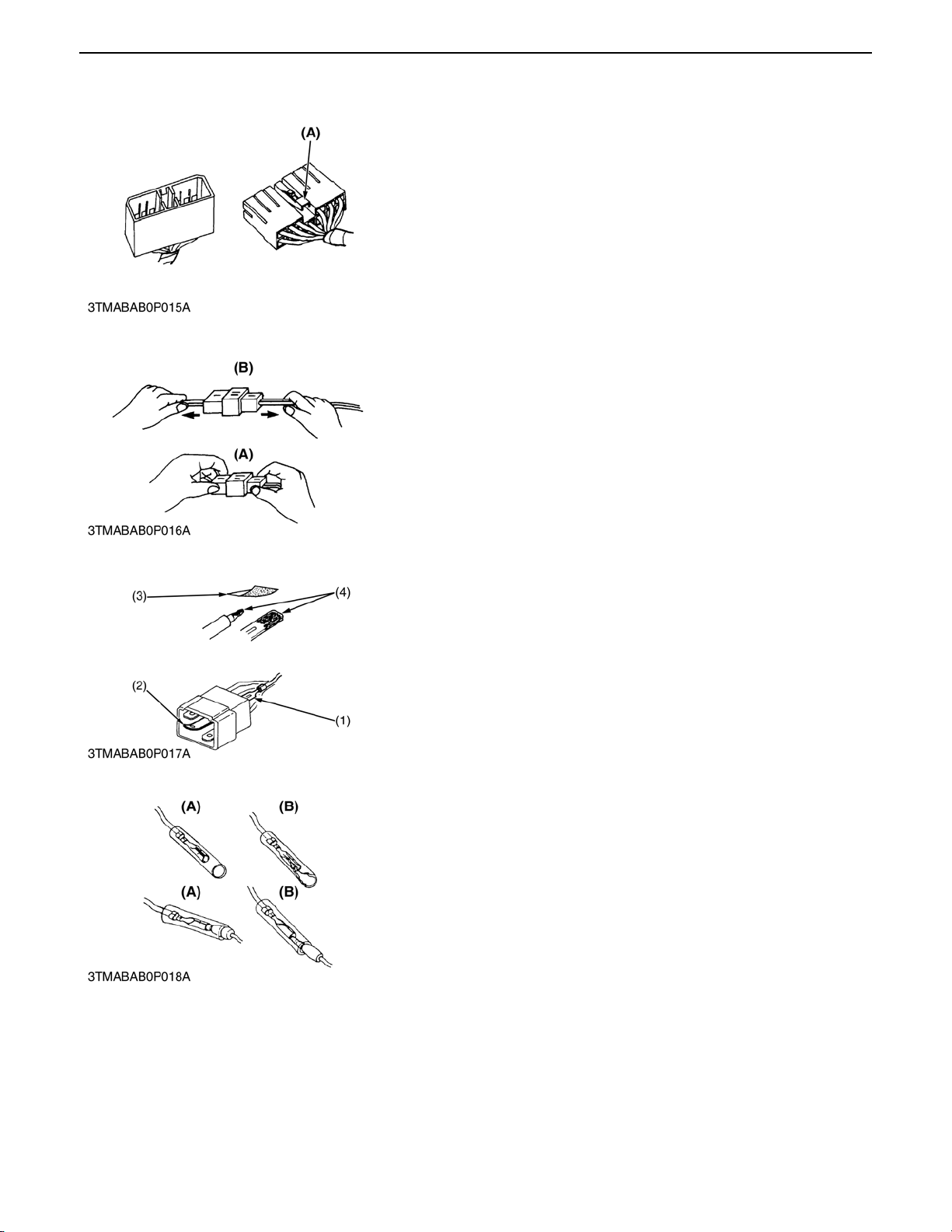
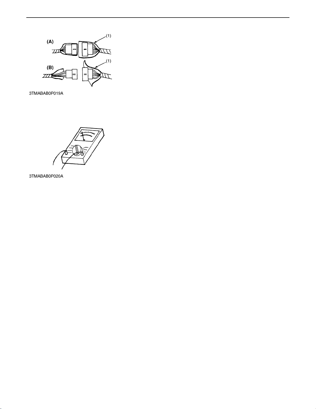
[4] CONNECTOR
A For connector with lock, push lock to separate.
(A) Push
0000000623E
A In separating connectors, do not pull wire harnesses.
A Hold connector bodies to separate.
(A) Correct (B) Incorrect
0000000624E
A Use sandpaper to remove rust from terminals.
A Repair deformed termin al. Make certain th ere is no terminal
being exposed or displaced.
(1) Exposed Terminal (3) Sandpaper
(2) Deformed Terminal (4) Rust
0000000625E
A Make certain that there is no female connector being too open.
(A) Correct (B) Incorrect
0000000626E
G-6
STV32 · STV36 · STV40, WSM GENERAL
KiSC issued 04, 2006 A
A Make certain plastic cover is large enough to cover whole
connector.
(1) Cover (A) Correct
(B) Incorrect
0000000627E
[5] HANDLING OF CIRCUIT TESTER
A Use tester correctly following manual provided with tester.
A Check for polarity and range.
0000000628E
G-7
STV32 · STV36 · STV40, WSM GENERAL
KiSC issued 04, 2006 A
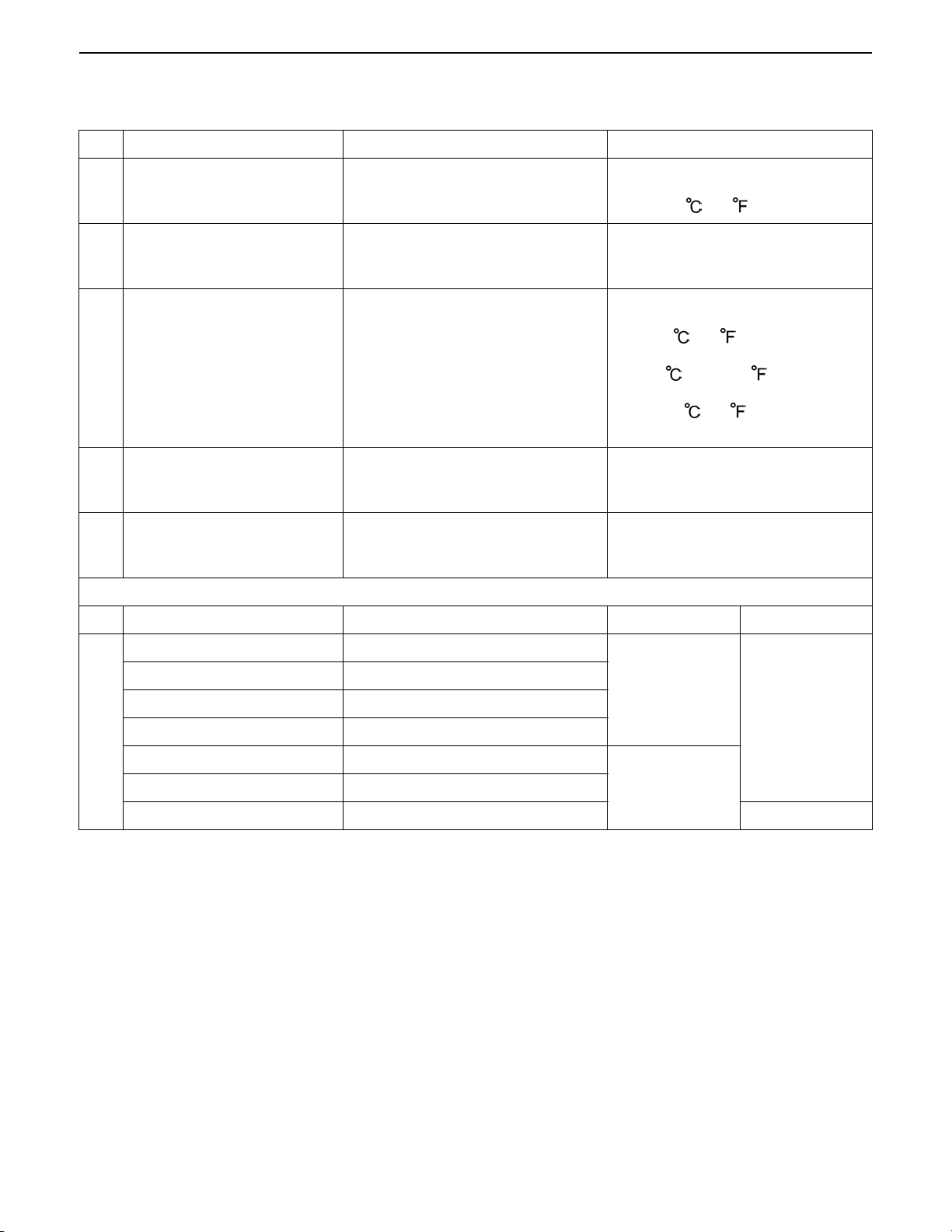
4. LUBRICANTS, FUEL AND COOLANT
Place Capacity Lubricants, fuel and coolant
1 Fuel tank
2 Coolant (with reserve tank)
3 Engine crankcase (with filter)
4 Transmission case
5 Front differential case oil
Place No. of greasing point Capacity Type of grease
29.5 L
7.79 U.S.gals.
6.49 lmp.gals.
6.1 L
6.4 U.S.qts.
5.4 lmp.qts.
6.7 L
7.1 U.S.qts.
5.9 lmp.qts.
22 L
5.81 U.S.qts.
4.84 lmp.qts.
4.0 L
4.2 U.S.qts.
3.5 lmp.qts.
Grease
No. 2-D diesel fuel
No. 1-D diesel fuel if temperature is
below -10 (14 )
Fresh clean water with anti-freeze
Engine oil: API service CC or CD
class
Below 0 (32 ) :
SAE10W, 10W-30 or 10W-40
0 to 25 (32 to 77 ) :
SAE20, 10W-30 or 10W-40
Above 25 (77 ) :
SAE30, 10W-30 or 10W-40
KUBOTA SUPER UDT fluid*
KUBOTA SUPER UDT fluid or
SAE80, 90 gear oil
Brake pedal shaft 1
Clutch pedal shaft 1
Top link 2
Lift rod 1
6
Battery terminal 2
Cruise control lever 2
Speed control wire Oiling Engine oil
*KUBOTA original transmission hydraulic fluid.
Until grease
overflows
Moderate
amount
Multipurpose
type grease
0000007958E
G-8
STV32 · STV36 · STV40, WSM GENERAL
KiSC issued 04, 2006 A
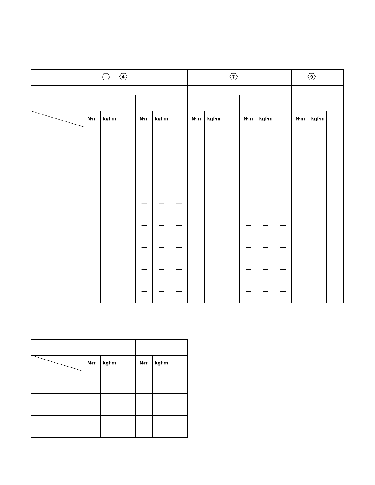
5. TIGHTENING TORQUES
[1] GENERAL USE SCREWS, BOLTS AND NUTS
Screws, bolt and n uts whose tightening torque are n ot specified in this Workshop M anual should be tightened
according to the table below.
Indication on top of
bolt
Material of bolt SS400, S20C S43C, S48C SCr435, SCM435
Material of
opponent part
Unit
Diameter
M6
(6 mm, 0.24 in.)
M8
(8 mm, 0.31 in.)
M10
(10 mm, 0.39 in.)
M12
(12 mm, 0.47 in.)
M14
(14 mm, 0.55 in.)
M16
(16 mm, 0.63 in.)
M18
(18 mm, 0.71 in.)
M20
(20 mm, 0.79 in.)
7.85
to
9.31
17.7
to
20.5
39.3
to
45.1
62.8
to
72.5
108
to
125
167
to
191
246
to
284
334
to
392
No-grade or 4T 7T 9T
Ordinariness Aluminum Ordinariness Aluminum Ordinariness
ft-lbs ft-lbs ft-lbs ft-lbs ft-lbs
0.80
5.79
7.85
0.80
5.79
9.81
1.00
7.24
7.85
0.80
5.79
12.3
to
0.95
1.8
to
2.1
4.0
to
4.6
6.4
to
7.4
11.0
to
12.8
17.0
to
19.5
25.0
to
29.0
34.0
to
40.0
to
6.87
13.1
to
15.1
29.0
to
33.2
46.3
to
53.5
79.6
to
92.5
123
to
141
181
to
209
246
to
289
to
8.82
16.7
to
19.6
31.4
to
34.3
to
0.90
1.7
to
2.0
3.2
to
3.5
to
6.50
12.3
to
14.4
23.2
to
25.3
to
11.2
23.6
to
27.4
48.1
to
55.8
77.5
to
90.2
124
to
147
197
to
225
275
to
318
368
to
431
to
1.15
2.4
to
2.8
4.9
to
5.7
7.9
to
9.2
12.6
to
15.0
20.0
to
23.0
28.0
to
32.5
37.5
to
44.0
to
8.31
17.4
to
20.2
35.5
to
41.2
57.2
to
66.5
91.2
to
108
145
to
166
203
to
235
272
to
318
to
8.82
17.7
to
20.5
39.3
to
44.1
62.8
to
72.5
to
0.90
1.8
to
2.1
4.0
to
4.5
6.4
to
7.4
to
6.50
13.1
to
15.1
29.0
to
32.5
46.3
to
53.5
to
14.2
29.5
to
34.3
60.9
to
70.6
103
to
117
167
to
196
260
to
304
344
to
402
491
to
568
1.25
to
1.45
3.0
to
3.5
6.2
to
7.2
10.5
to
12.0
17.0
to
20.0
26.5
to
31.0
35.0
to
41.0
50.0
to
58.0
9.05
to
10.4
21.7
to
25.3
44.9
to
52.0
76.0
to
86.7
123
to
144
192
to
224
254
to
296
362
to
419
[2] STUD BOLTS
Material of oppone t
Unit
Diameter
(8 mm, 0.31 in.)
(10 mm, 0.39 in.)
(12 mm, 0.47 in.)
part
M8
M10
M12
Ordinariness Aluminum
ft-lbs ft-lbs
11.8
15.6
24.6
31.3
29.5
49.0
to
to
to
1.2
to
1.6
2.5
to
3.2
3.0
to
5.0
8.68
8.82
to
11.5
18.1
23.1
21.7
36.1
to
11.8
19.7
to
to
25.4
to
31.4 3.2 23.1
0.90
to
1.2
2.0
to
2.6
0000000766E
6.51
to
8.67
14.5
to
18.8
0000000767E
G-9

STV32 · STV36 · STV40, WSM GENERAL
KiSC issued 04, 2006 A
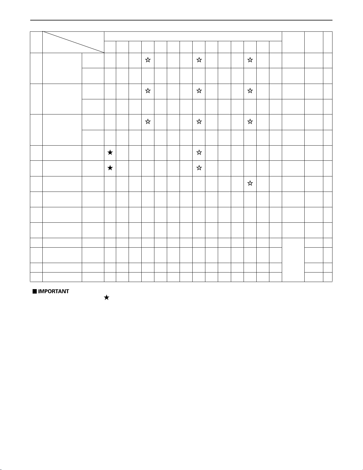
6. MAINTENANCE CHECK LIST
Period
No.
Item
1 Greasing -
Engine start
2
system
Wheel bolt
3
torque
4 Engine oil Change
5 Brake pedal Adjust
6 Fan belt Adjust
7 Clutch pedal Adjust
Battery
8
condition
Air cleaner
9
element
[Single type]
Air cleaner
element
[Double type]
(Primary
element)
10
Air cleaner
element
[Double type]
(Scondary
element)
Fuel filter
11
element
12 Parking brake Adjust
13 Fuel line
14 Engine oil filter Replace
Hydraulic oil
15
filter
Hydraulicoil filter
16
[HST]
17 Toe-in Adjust
Check
Check
Check
Clean
Replace
Clean
Replace
Replace
Clean
Replace
Check
Replace
Replace
Replace
Indication on hour meter
50 100 150 200 250 300 350 400 450 500 550 600 650 700
After
since
every
50Hr
every
50Hr
every
50Hr
every
100Hr
every
100Hr
every
100Hr
every
100Hr
every
100Hr
every
100Hr
every 1
year
every
100Hr
every 1
year
every 1
year
every
100Hr
every
400Hr
every
100Hr
every
100Hr
every 2
years
every
200Hr
every
200Hr
every
200Hr
every
200Hr
Refer-
ence
page
G-18,
19
G-19
G-20
G-13
G-23
G-23
G-17
G-25 *4
G-21 *1
G-21
G-21 *1
G-21 *2
G-21
G-22
G-22
G-24
G-22
G-22 *3
G-14
G-16
G-16
G-29
G-10
STV32 · STV36 · STV40, WSM GENERAL
KiSC issued 04, 2006 A
Period
No.
Item
Radiator hose
18
and clamp
Power steering
19
hose
HST oil line
20
[HST]
Transmission
21
fluid
Front axle case
22
oil
23 Front axle pivot Adjust
Engine valve
24
clearance
25 Cooling system Flush
26 Coolant Change
27 Fuel system Bleed
Clutch housing
28
water
29 Fuse Replace G-34
30 Light bulb Replace G-35
Check
Replace
Check
Replace
Check
Replace
Change
Change
Adjust
Drain G-33
50 100 150 200 250 300 350 400 450 500 550 600 650 700
Indication on hour meter
After
since
every
200Hr
every 2
years
every
200Hr
every 2
years
every
200Hr
every 2
years
every
400Hr
every
400Hr
every
600Hr
every
800Hr
every 2
years
every 2
years
Service
as
required
Refer-
ence
page
G-27
G-27 *3
G-28
G-28
G-28
G-28 *3
G-15
G-16
G-30
1-S13
G-31
G-31
G-33
A The jobs indicated by must be done after the first 50 hours of operation.
A *1 : Air cleaner should be cleaned more often in dusty conditions than in normal conditions.
A *2 : Every year or every 6 times of cleaning.
A *3 : Replace only if necessary.
A *4 : When the battery is used for less than 100 hours per year, check the battery condition by reading
the indication annually.
0000007959E
G-11

STV32 · STV36 · STV40, WSM GENERAL
KiSC issued 04, 2006 A
7. CHECK AND MAINTENANCE
A Be sure to check and serv ice the tractor on a flat place with engine shut off , the parkin g brake on and
chock the wheels.
0000000633E
[1] DAILY CHECK
To prevent troubl e from occ urring, it is important to know t he condition of the tra ctor. Check the foll owing items
before starting.
Checking
A Check areas where previous trouble was experienced.
A Walk around the tractor.
1. Check the tire pressure, and check for wear and damage.
2. Check for oil and water leak.
3. Check the engine oil level.
4. Check the transmission fluid level.
5. Check the coolant level.
6. Check the condition of seat belt and ROPS attaching hardware.
7. Check and clean the radiator screen and grill.
8. Check the screws and nuts of tires are tight.
9. Check the number plate.
10.Care of danger, warning and caution labels
11.Clean around the exhaust manifold and the muffler of the engine.
A While sitting in the operator's seat.
1. Check the HST pedal, brake pedals and clutch pedal.
2. Check the parking brake.
3. Check the steering wheel.
A Turning the key switch .
1. Check the performance of the easy checker lights.
2. Check the lights, turn signal lights, hazard lights and other light equipment. Clean if necessary.
3. Check the performance of the meters and gauges.
A Starting the engine,
1. Check to see that the lights on the easy checker go off.
2. Check the color of the exhaust gas.
3. Check the brakes for proper operation.
0000007965E
G-12
STV32 · STV36 · STV40, WSM GENERAL
KiSC issued 04, 2006 A
[2] CHECK POINTS OF INITIAL 50 HOURS
Changing Engine Oil
A Before changing oil, be sure to stop the engine.
1. Start and warm up the engine for approx. 5 minutes.
2. Place an oil pan underneath the engine.
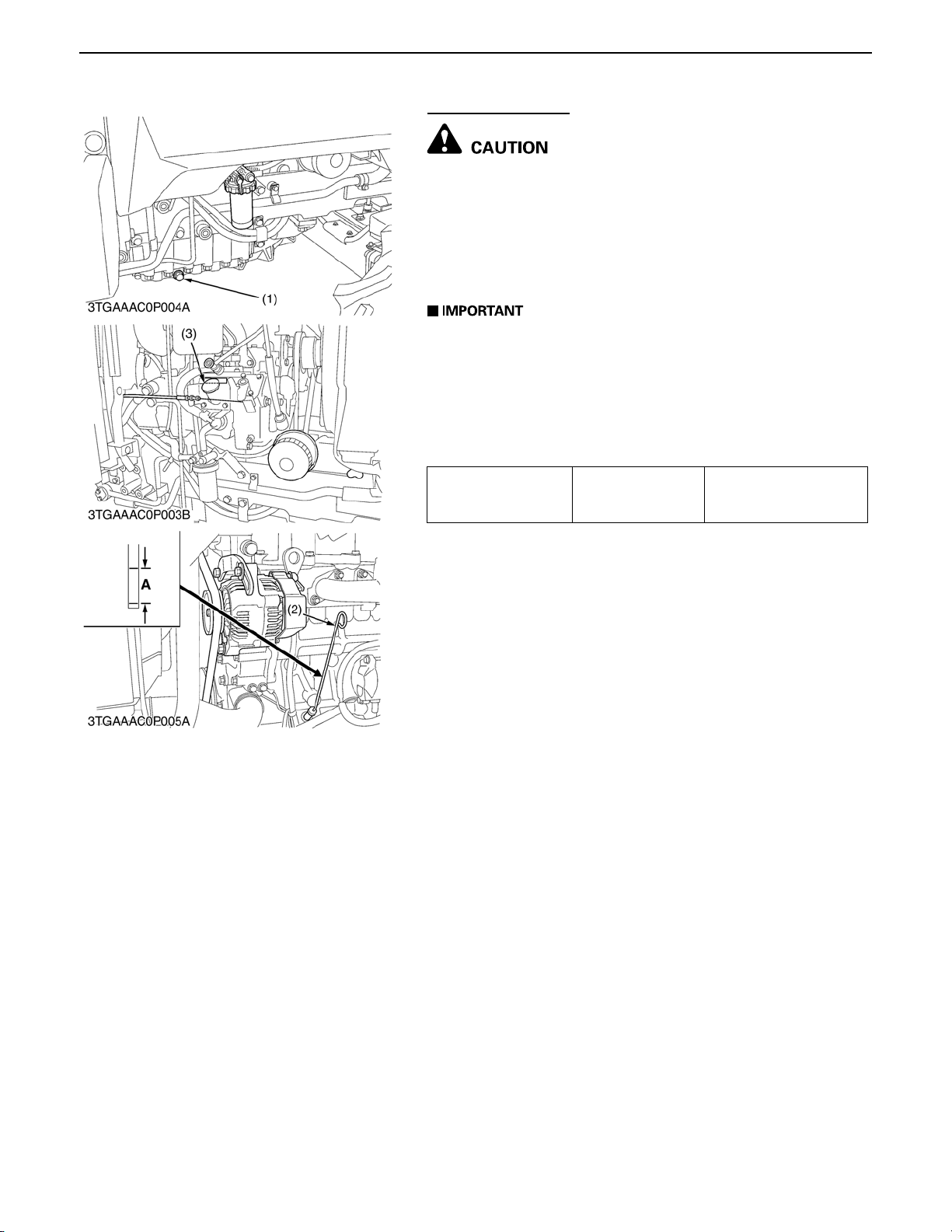
3. To drain the used oil, rem ove the dr ain plu g (1) at the b ottom
of the engine and drain the oil completely.
4. Screw in the drain plug (1).
5. Fill new oil up to upper line on the dipstick (2).
A When using an oil of different manufacture or viscosity
from the previous one, remove all of the old oil.
A Never mix two different types of oil.
A Use the proper SAE Engine Oil according to ambient
temperatures.
A Refer to "LUBRICANTS, FUEL AND COOLANT". (See
page G-8.)
Engine oil Capacity
6.7 L
7.1 U.S.qts
5.9 lmp.qts
(1) Drain Plug (A) Oil level is acceptable within
(2) Dipstick this range.
(3) Oil Inlet Plug
0000007967E
G-13
STV32 · STV36 · STV40, WSM GENERAL
KiSC issued 04, 2006 A
Replacing Engine Oil Filter Cartridge
A Be sure to stop the engine before changing oil filter
cartridge.
A Allow engine to cool down sufficiently, oil can be hot and
can burn.
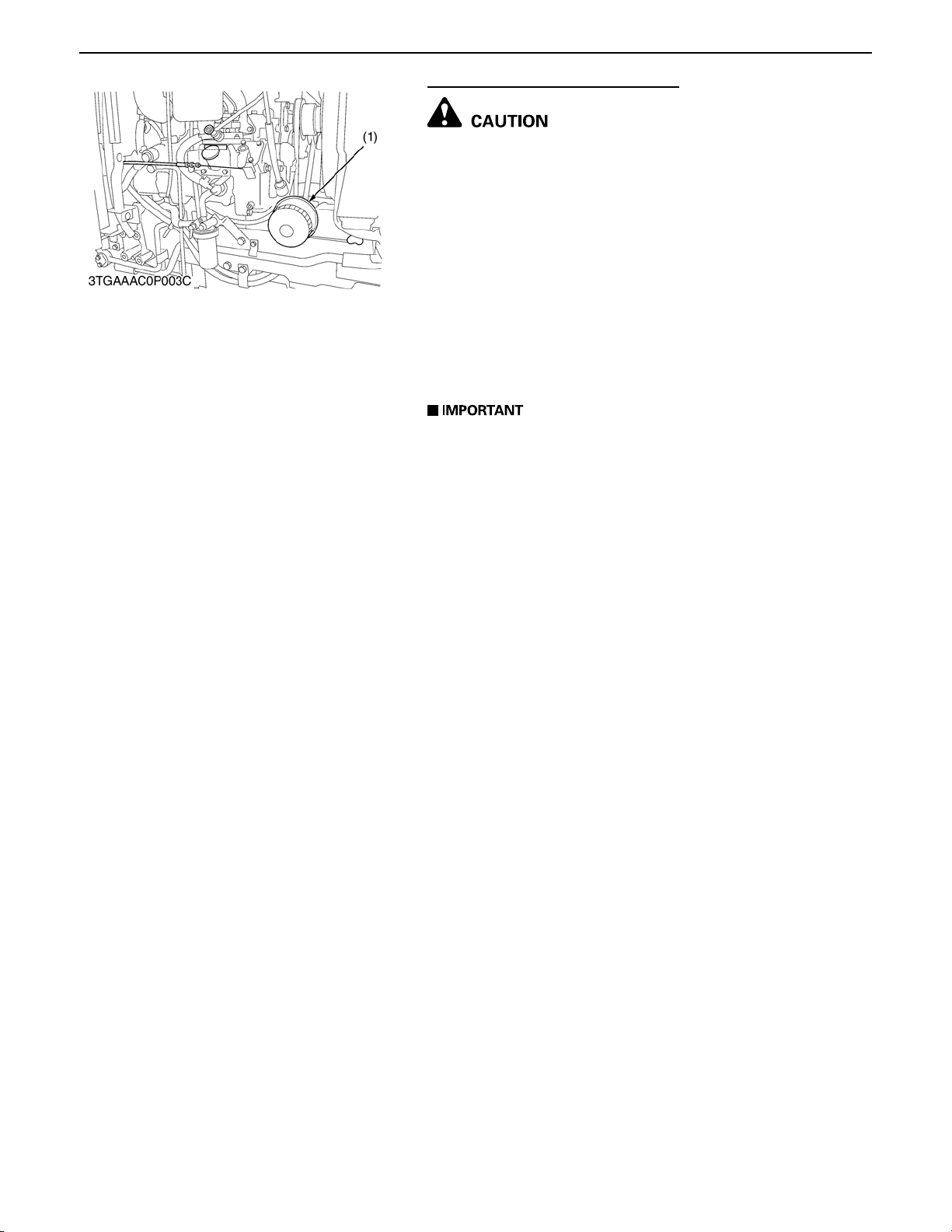
1. Remove the oil filter cartridge with the filter wrench.
2. Apply a slight coat of oil onto the rubber seal of new filter.
3. To install the new cartridge, screw it in by hand. Over
tightening may cause deformation of rubber gasket.
4. After the new cartridge has been replaced, the engine oil
normally decrease a little. Thus see that the eng ine oil d oes
not leak through the seal and be sure to read the oi l level on
the dipstick. Then, replenish the engine oil up to the specified
level.
A To prevent serious damage to the engine, replacement
filter must be highly efficient. Use only a KUBOTA
genuine filter or its equivalent.
(1) Engine Oil Filter
0000007968E
G-14
STV32 · STV36 · STV40, WSM GENERAL
KiSC issued 04, 2006 A
Changing Transmission Flu id
A Be sure to stop the engine when checking and changing
the transmission fluid.
A Allow engine to cool down sufficiently, oil can be hot and
can burn.
1. Place an oil pan under the tractor.
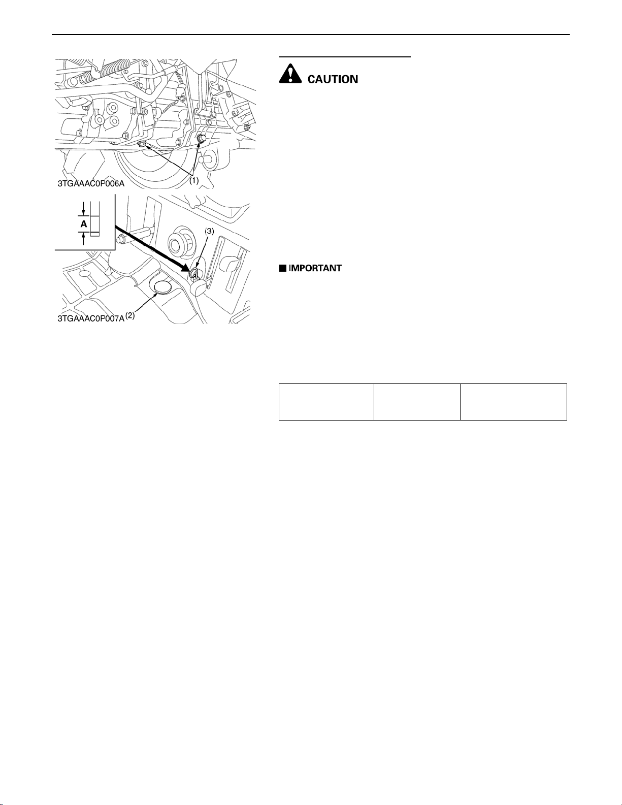
2. Remove the drain plug (1) at the bottom of the transmission
case.
3. Drain the transmission fluid.
4. After draining, screw in the drain plug.
5. Fill new oil from filling port after removing the filling plug (2) up
to the upper notch on the dipstick.
6. After running the eng ine for a few minu tes, stop it a nd check
the oil level again, if low, add oil to the prescribed level.
A Use only multi-grade transmission oil. Use of other oils
may damage the transmission or hydraulic system.
Refer to "LUBRICANTS, FUEL AND COOLANT" (See
page G-8.).
A Never work the tractor immediately after changing the
transmission oil. Keeping the engine at medium speed
for a few minutes to prevents dama ge to the transmission.
A Do not mix different blands oil together.
Transmission fluid Capacity
22 L
5.81 U.S.gals
4.84 Imp.gals
(1) Drain Plug A : Oil level is acceptable within
(2) Filling Plug this range.
(3) Dipstick
0000007969E
G-15
STV32 · STV36 · STV40, WSM GENERAL
KiSC issued 04, 2006 A
Replacing Hydrauli c Oil Filter Cartridge
A Be sure to stop the engine before changing the oil filters.
A Allow engine to cool down sufficiently, oil can be hot and
can burn.
1. Drain the transmission fluid.
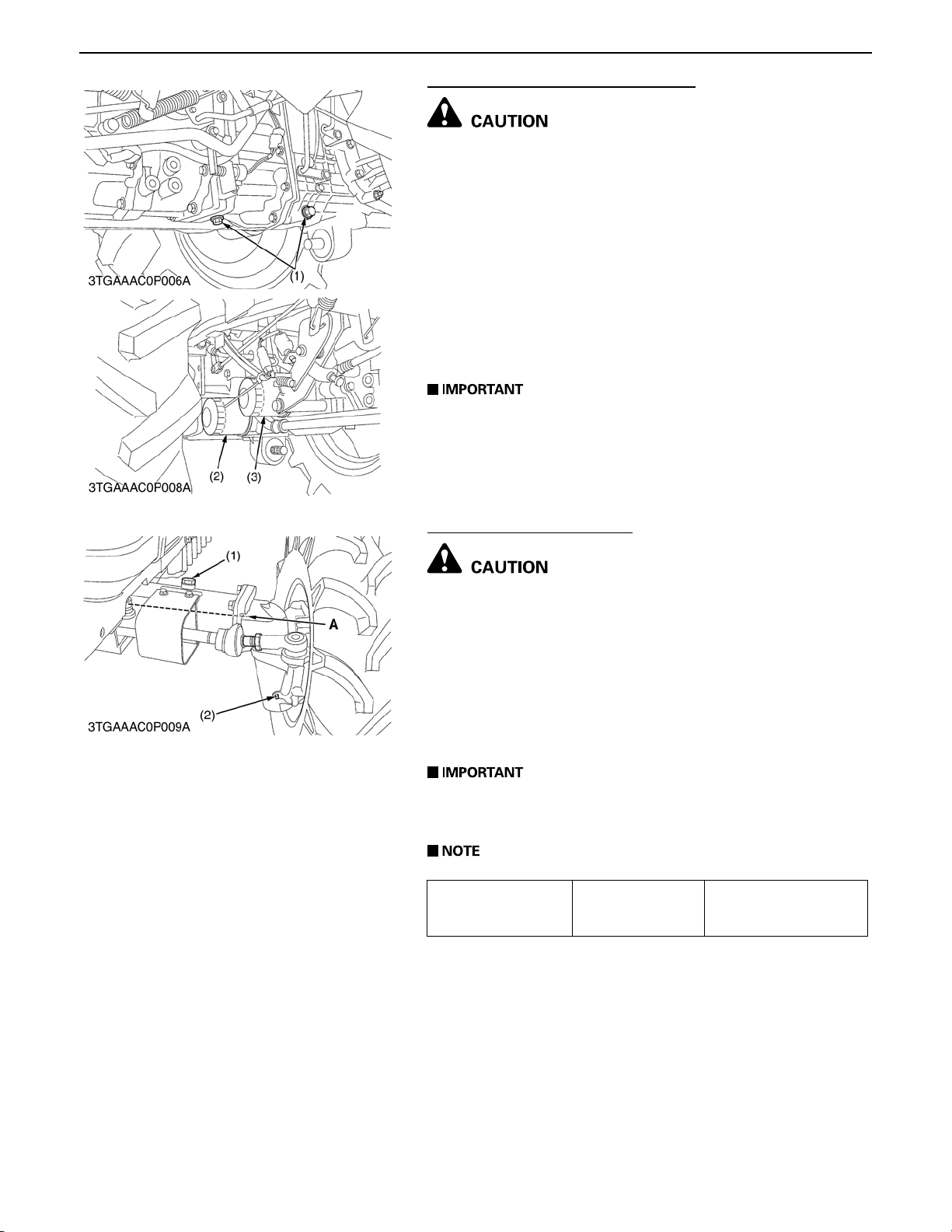
2. Remove the both oil filter cartridges by using a filter wrench.
3. Apply a slight coat of oil onto the new cartridge gasket.
4. To install the new cartridge, screw it in by hand. Over
tightening may cause deformation of rubber gasket.
5. After the new cartridge ha s been replaced, the transmissio n
fluid level will normally decrease slightl y. Make sure that the
transmission fl uid does n ot leak through the seal. Check the
fluid level.
A To prevent serious damage to the hydraulic system. Use
only a genuine KUBOTA filter or its equivalents.
(1) Drain Plug (3) Hydraulic Oil Filter (for HST)
(2) Hydraulic Oil Filter
0000007970E
Changing Front Axle Case Oil
A Be sure to stop the engine before changing the front axle
case oil.
A Allow engine to cool down sufficiently, oil can be hot and
can burn.
1. Remove the both right and left drain plugs (2) at bottom of the
bevel gear case.
2. Drain the front axle case oil.
3. After draining, screw in the two drain plugs.
4. Fill new oil from filling port with specified amount.
A Use KUBOTA SUPER UDT fluid or SAE 80, 90 gear oil.
Refer to "LUBRICANTS, FUEL AND COOLANT" (See
page G-8.)
A Oil level is at the center of the front axle.
Front axle case oil Capacity
4.0 L
1.06 U.S.gals.
0.88 Imp.gals.
(1) Filling Plug A : Oil Level
(2) Drain Plug
0000007971E
G-16
 Loading...