

Page 1

K UBOT A
Page 2

3
WARNING
To prevent electrical shock the following instruction must be followed.
Before the generator can be connected to a building’s electrical
system, a licensed electrician must install an isolation (transfer)
switch in the building’s main fuse box. The switch is the connection
point for generator power and allows selection of generator or main
line power to the building.
This will prevent the generator from charging the main power line
(backfeeding) when the main power supply has failed or has been
turned off for line repair. Backfeeding can electrocute or injure line
maintenance personnel. Also, generator and building electrical
system damage can occur when normal operating power returns if
unit is used without an isolation switch.
Page 3

FOREWORD
You are now the proud owner of a KUBOTA Diesel Engine Generator. This generator is a product of KUBOTA quality engineering and manufacturing. It is
made of fine materials and under a rigid quality control system with correct
maintenance. It will give you long, satisfactory service. To obtain the best use
of your generator, please read this manual carefully. It will help you become
familiar with the operation of the generator and contains many helpful hints
about generator maintenance. It is KUBOTA's policy to utilize as quickly as
possible every advance in our research. The immediate use of new techniques
in the manufacture of products may cause some small parts of this manual to
be outdated. KUBOTA distributors and dealers will have the most up-to-date
information. Please do not hesitate to consult with them.
3
SAFETY FIRST
This symbol, the industry's "Safety Alert Symbol", is used throughout this
manual and on labels on the machine itself to warn of the possibility of personal
injury. Read these instructions carefully. It is essential that you read the instructions and safety regulations before you attempt to assemble or use this unit.
3
DANGER : Indicates an imminently hazardous situation which, if not
avoided, will result in death or serious injury.
3
WARNING : Indicates a potentially hazardous situation which, if not
avoided, could result in death or serious injury.
3
CAUTION: Indicates a potentially hazardous situation which, if not
avoided, may result in minor or moderate injury.
IMPORTANT : Indicates that equipment or property damage could result
if instructions are not followed.
NOTE : Gives helpful information.
Page 4

CONTENTS
SAFE OPERATION ..................................................................................................1
SERVICING OF GENERATOR........ ............................................................................1
SPECIFICATIONS .......................................................................................................2
Part Names ......................................................................................................................3
INSTRUMENT PANEL AND PART NAMES................................................................4
Control Panel......... ....... ....... ............................................................... ....... ....... ....... ......... 4
Control Box................... ....... ....... ............................................................... ....... ....... ......... 5
PREPARATION TO SUPPLY THE ELECTRIC POWE R.............................................6
CONNECTING THE LOAD... .......................................................................................8
Connection Notes............................................................................................................. 8
Connecting the Load ........................................................................................................ 8
PRE-OPERATION CHECK.............. ..........................................................................10
DAILY CHECK........................................................................................................10
How to Open the Door.................................................................................................... 10
Battery............................................................................................................................10
Engine Oil.......................................................................................................................11
Coolant...........................................................................................................................11
Opening and Closing of the Fuel Tank Cap ...................................................................11
Fuel ................................................................................................................................12
OPERATING THE GENERATOR............................ ..................................................13
SAFETY DEVICES.................. ... ............................................................................13
STARTING THE ENGINE ......................................................................................14
Warm-up in Cold Ambient Temperatures.......................................................................15
COLD WEATHER STARTING ...............................................................................16
STOPPING THE ENGINE ......................................................................................17
EMERGENCY STOP SWITCH ..............................................................................18
MAINTENANCE.........................................................................................................19
SERVICE INTERVALS...........................................................................................20
PERIODIC SERVICE. ................................................................................................22
FUEL ......................................................................................................................22
Fuel Level Check and Refueling .................................................................................... 22
Air Bleeding the Fuel System......................................................................................... 23
Cleaning the Fuel Filter Element.................................................................................... 23
Fuel Filter Cartridge Replacement .................................................................................24
Cleaning the Water Separator (Sedimenter).................................................................. 24
Draining Water in the Fuel Tank........ ....... ....... ....... ....... ....... .......................................... 25
ENGINE OIL...........................................................................................................25
Checking Oil Level and Adding Engine Oil.....................................................................26
Changing Engine Oil ......................................................................................................27
Replacing the Oil Filter Cartridge ...................................................................................27
RADIATOR.............................................................................................................28
Checking Coolant Level, Adding Coolant....................................................................... 28
Changing Coolant........................................................................................................... 29
Remedies for Rapid Coolant Loss.................................................................................. 29
Checking Radiator Hoses and Clamps .......................................................................... 30
Precaution Overheating.................................................................................................. 30
Page 5

CONTENTS
Cleaning Radiator Core (outside)...................................................................................30
Cleaning the Radiator (inside)........................................................................................30
Anti-freeze......................................................................................................................30
AIR CLEANER........................................................................................................31
Cleaning Primary Air Filter Element ...............................................................................32
Evacuator Valve ............................................................................................................. 32
For the Air Cleaner with a Dust Cup............................................................................... 32
BATTERY...............................................................................................................32
Battery Charging ............................................................................................................32
Instructions for Long Term Storage................................................................................34
Battery Boost Starting ....................................................................................................34
ELECTRIC WIRING ......................... ......................................................................34
FAN BELT ... .. .........................................................................................................35
Adjusting Fan Belt Tension ............................................................................................35
FULLY BUNDED ................. .. .................................................................................35
TRANSPORTING / STORAGE..................................................................................36
Transporting ...................................................................................................................36
Lifting Procedure ............................................................................................................ 36
Storage...........................................................................................................................37
OPERATION OF THE EMERGENCY RELAY...........................................................38
TROUBLESHOOTING...............................................................................................40
When it is Difficult to Start the Engine............................................................................ 40
When Starter does not Start...........................................................................................40
When Output is Insufficient .................................... ....... ....... ....... ....... ....... .....................41
When Engine Suddenly Stops........................................................................................41
When Color of Exhaust Smoke is Black and Excessive................................................. 41
When Engine must be Stopped Immediately ............................................................ 42
When Engine Overheats ................................................................................................42
Generator Troubleshooting ............................................................................................43
WIRING DIAGRAM....................................................................................................45
Page 6
SAFE OPERATION
Careful operation is your best insurance against an accident. Read and understand this
operator’s manual carefully before operating the generator. All operators, no matter how
much experience they may have had, should read this manual and all labels on the
generator before operating the generator. It is the owner's responsibility to instruct all
operators in safe operation.
Be sure to observe the following for safe operation.
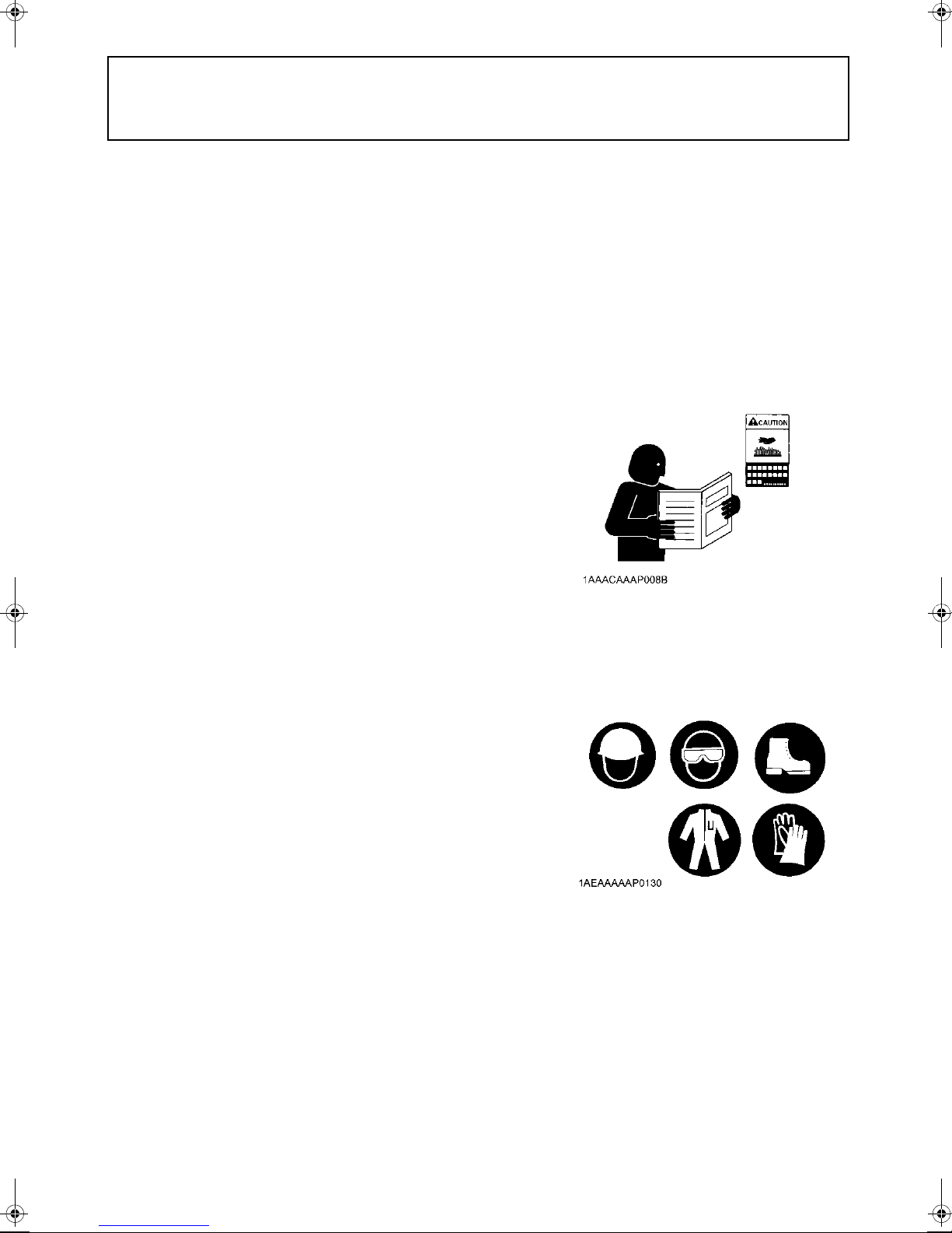
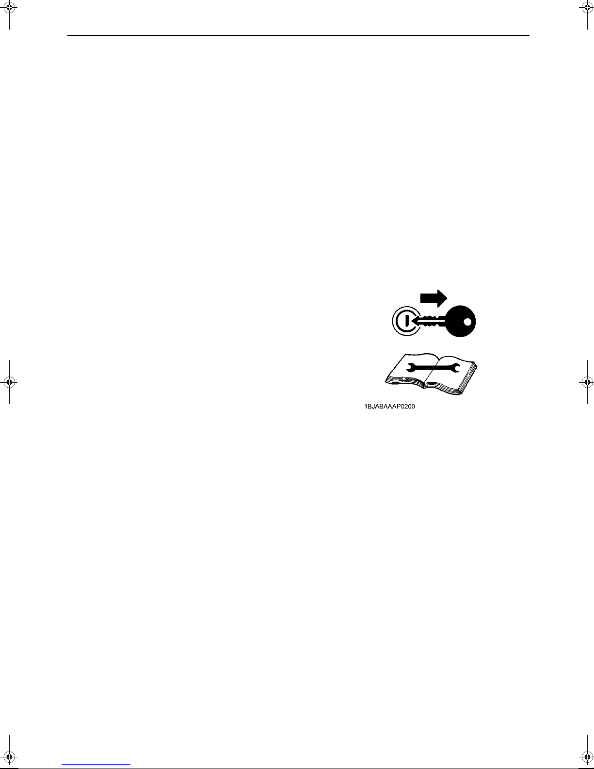
OBSERVE SAFETY INSTRUCTIONS
A Read and understand carefully this OPERATOR'S
MANUAL and LABELS ON THE GENERATOR before
attempting to start and operate the generator.
A Learn how to operate and work safely. Know your
equipment and its limitations. Always keep the generator
in good condition.
A Before allowing other people to use your generator,
explain to them how to operate and have them read this
manual before operation.
A DO NOT modify the engine by yourself.
UNAUTHORIZED MODIFICATIONS to the engine may
impair the function and / or safety and affect engine life.
1SAFE OPERATION
WEAR SAFETY CLOTHING
A DO NOT wear loose, torn or bulky clothing around the
generator that may catch on working controls and
projections causing personal injury.
A Use additional safety items, e.g. hard hat, safety
protections, gloves, etc., as appropriate or required.
A DO NOT operate generator or any equipment attached to
it while under the influence of alcohol, medication, or
other substances, or while fatigued.
A DO NOT wear radio or music headphones while
operating the generator.
Page 7
SAFE OPERATION2
CHECK BEFORE OPERATION & STARTING THE ENGINE
A Always turn off the circuit breaker and all switches for the
electrical devices before starting the generator.
A Check the wiring and connections of the electrical
devices before starting the generator.
A Be sure to check the engine before operation. If
something is wrong with the engine, repair it immediately
and before operation.
A Keep all guards and shields in place before operating the
generator. Replace any that are damaged or missing.
A Check to see that bystanders are in a safe distance from
the generator before starting.
A Always keep the generator at least 1 m away from
buildings and other facilities.
A DO NOT allow children or livestock to approach the
generator while the engine is running.
A DO NOT start the engine by shorting across starter
terminals or bypassing normal starting circuit. The
generator may start unexpectedly causing electric shock
to others.
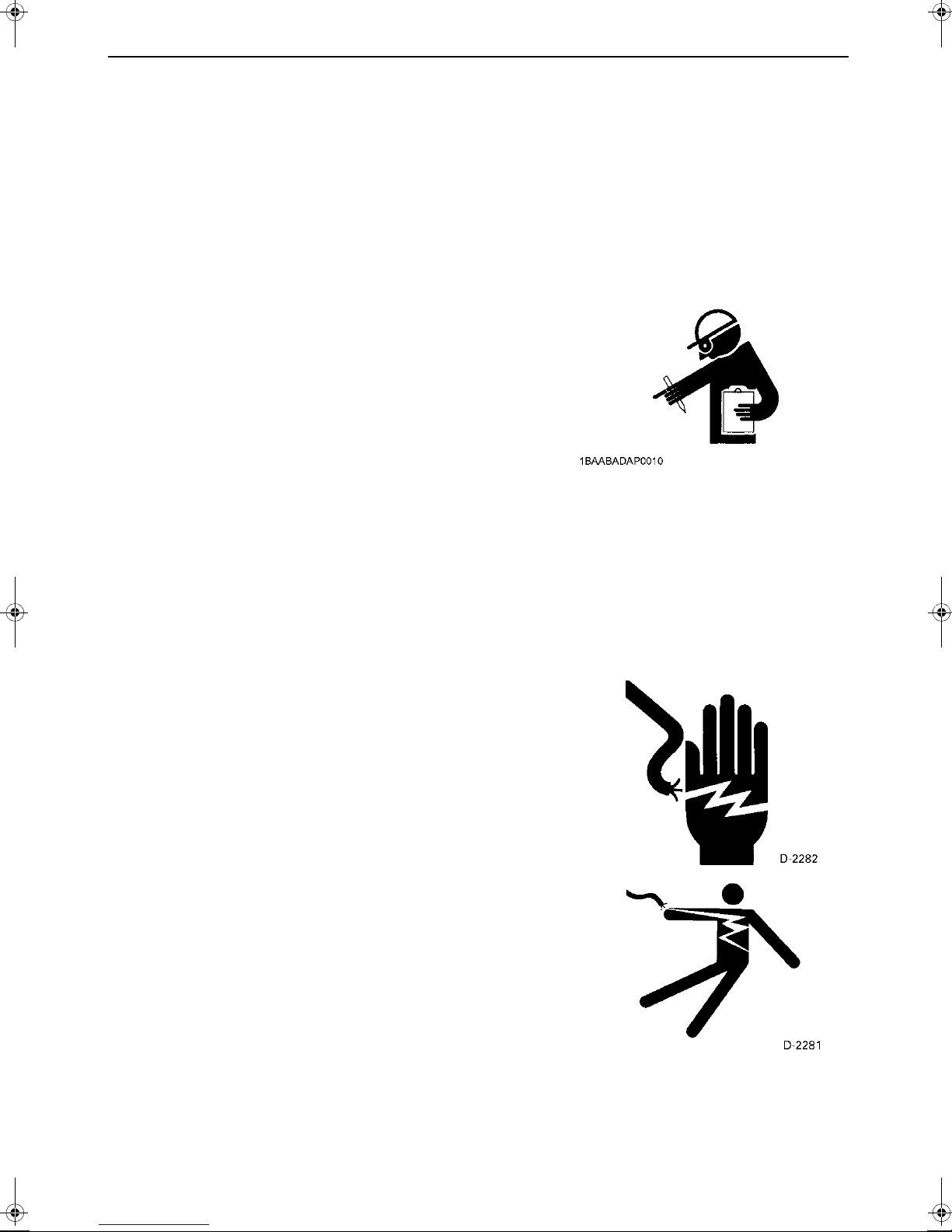
HANDLING ELECTRICAL COMPONENTS
Always exercise extra caution when handling electrical
equipment. Careless handling of electrical components can
cause serious personal injury, death by electrocution or
property damage.
A DO NOT touch the electrical system during operation.
A Connect or disconnect the load to the AC receptacles or
terminals only when the engine is stopped.
A Make certain that all power cables and wiring are in good
condition. Bare wire or frayed insulation can cause
dangerous electrical shock, burns or death.
A DO NOT use the generator in damp or wet conditions.
Handling terminals and cables with wet hands can result
in personal injury or death.
A Always shut the engine off and allow to cool before
cleaning. Use water sparingly when cleaning the outside
of the generator. Make sure that water does not splash
onto the electrical system or into the generator.
A DO NOT touch the generator with wet hands. You may
get an electric shock that can cause burns or death.
A DO NOT connect this generator to any building's
electrical system unless an isolation switch has been
installed by a licensed electrician.
A DO NOT run other generators in parallel.
Page 8
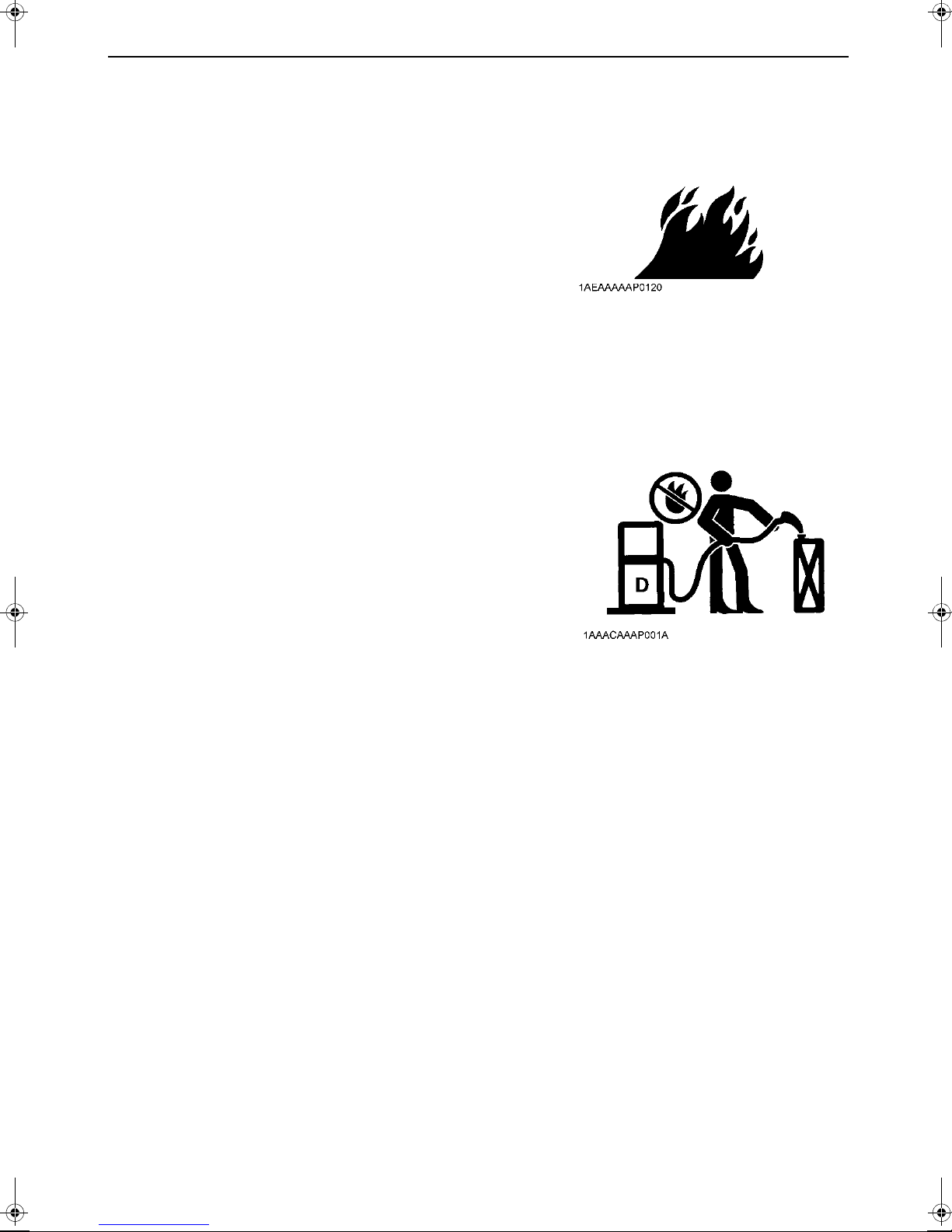
KEEP THE AREA AROUND THE ENGINE CLEAN
A Be sure to stop the engine before cleaning.
A Keep the engine clean and free of accumulated dirt,
grease and trash to avoid a fire. Store flammable fluids
away from sparks and fire.
A DO NOT stop the engine without idling. Sudden stops
can cause temperatures around the engine to rise
suddenly. Keep the engine idling for about 5 minutes
before stopping.
SAFE HANDLING OF FUEL AND LUBRICANTS
A Always stop the engine before refueling and/or
lubricating.
A DO NOT smoke or allow flames or sparks in the working
area. Fuel is extremely flammable and explosive under
certain conditions.
A Refuel only when the engine has cooled off. Refuel in a
well ventilated and open place. When fuel and lubricants
are spilled, clean them up before starting the engine.
A DO NOT mix gasoline or alcohol with diesel fuel. The
mixture can cause a fire and damage engine
components.
A Operate the generator on a firm and level surface only.
DO NOT tilt or move the generator while it is running
since this can cause fuel spillage.
3SAFE OPERATION
Page 9
SAFE OPERATION4
EXHAUST GASES & FIRE PREVENTION
A Engine exhaust fumes can be very harmful if allowing
them to accumulate. Be sure to run the engine in a well
ventilated place and where there are no people or
livestock near the generator.
A DO NOT operate the generator in a closed area such as
inside houses, warehouses, tunnels, wells, ship holds,
tanks, etc. or places without proper ventilation.
A DO NOT operate the generator where the building or
other obstructions block off air circulation or where
exhaust gas can accumulate.
A The exhaust gas from the muffler is very hot. To prevent
a fire, DO NOT expose to dry grass, papers, oil and any
other combustible materials to exhaust gas. Also, keep
the engine and muffler clean at all times.
A To avoid fire, be alert for leaks of flammables from hoses
and lines. Be sure to check for leaks from hoses or pipes,
such as fuel and engine oil by following the maintenance
check list.
A To avoid a fire, DO NOT short across power cables and
wires.
Check to see that all power cables and wiring are in good
condition.
A Keep all power connections clean and tight. Bare wire or
frayed insulation can cause a dangerous electrical shock
and personal injury.
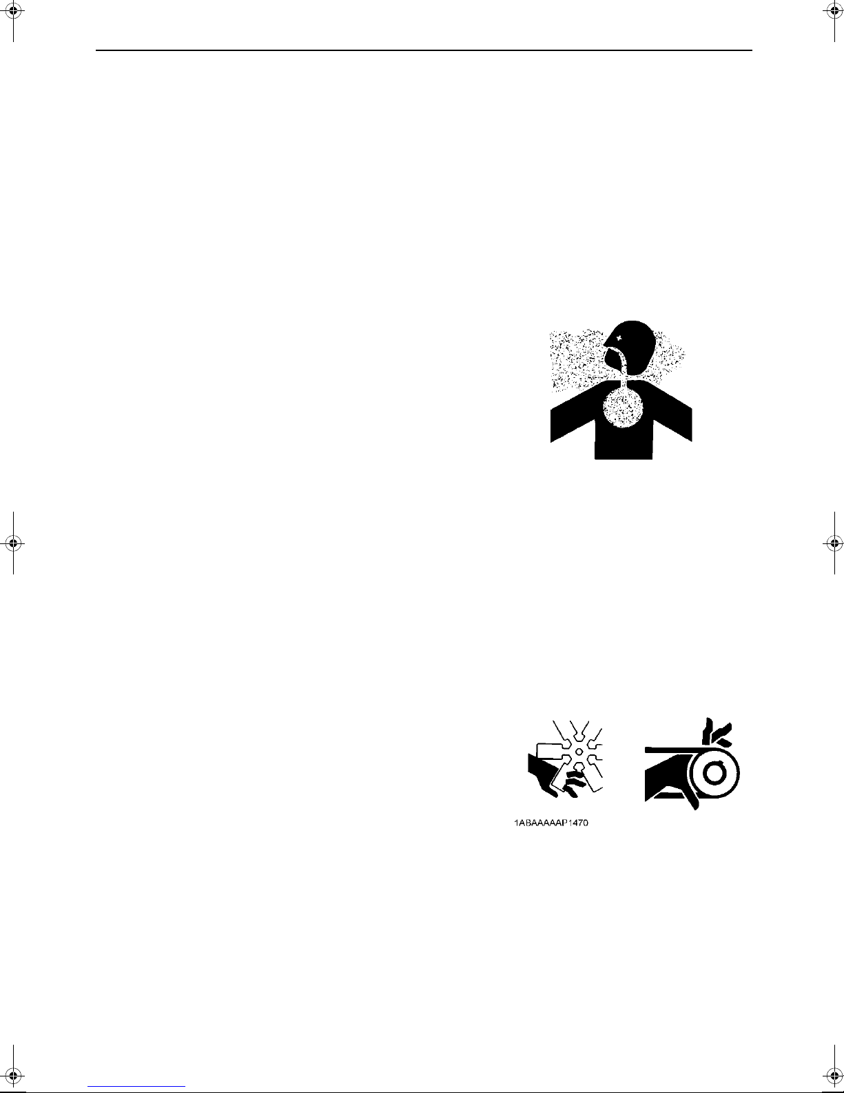
HANDS AND BODY AWAY FROM THE ROTATING PARTS
A DO NOT operate the generator with the side covers
removed or open. Serious personal injury may result if
fingers or clothing are caught in the rotating parts.
A Be sure to stop the engine before checking or adjusting
belt tension and cooling fan.
A To avoid personal injury, keep your hands and body
away from the rotating parts, such as cooling fan, V-belt,
fan drive V-belt, pulleys or flywheel.
A DO NOT run the engine with installed safety guards
detached. Install safety guards securely before
operation.
Page 10

ESCAPING FLUID
A Relieve all pressure in the oil and the cooling systems
before any lines, fittings or related items are removed or
disconnected.
A Be alert for possible pressure when disconnecting any
device from a system that utilizes pressure.
DO NOT check for pressure leaks with your hand.
High pressure oil or fuel can cause serious personal
injury.
A Escaping fluid under pressure has sufficient force to
penetrate skin causing serious personal injury.
A Fluid escaping from pinholes may be invisible.
Use a piece of cardboard or wood to search for
suspected leaks: DO NOT use hands or body. Use safety
goggles or other eye protection when checking for leaks.
A If injured by escaping fluid, see a medical doctor at once.
This fluid can produce gangrene or severe allergic
reaction.
5SAFE OPERATION
Page 11
SAFE OPERATION6
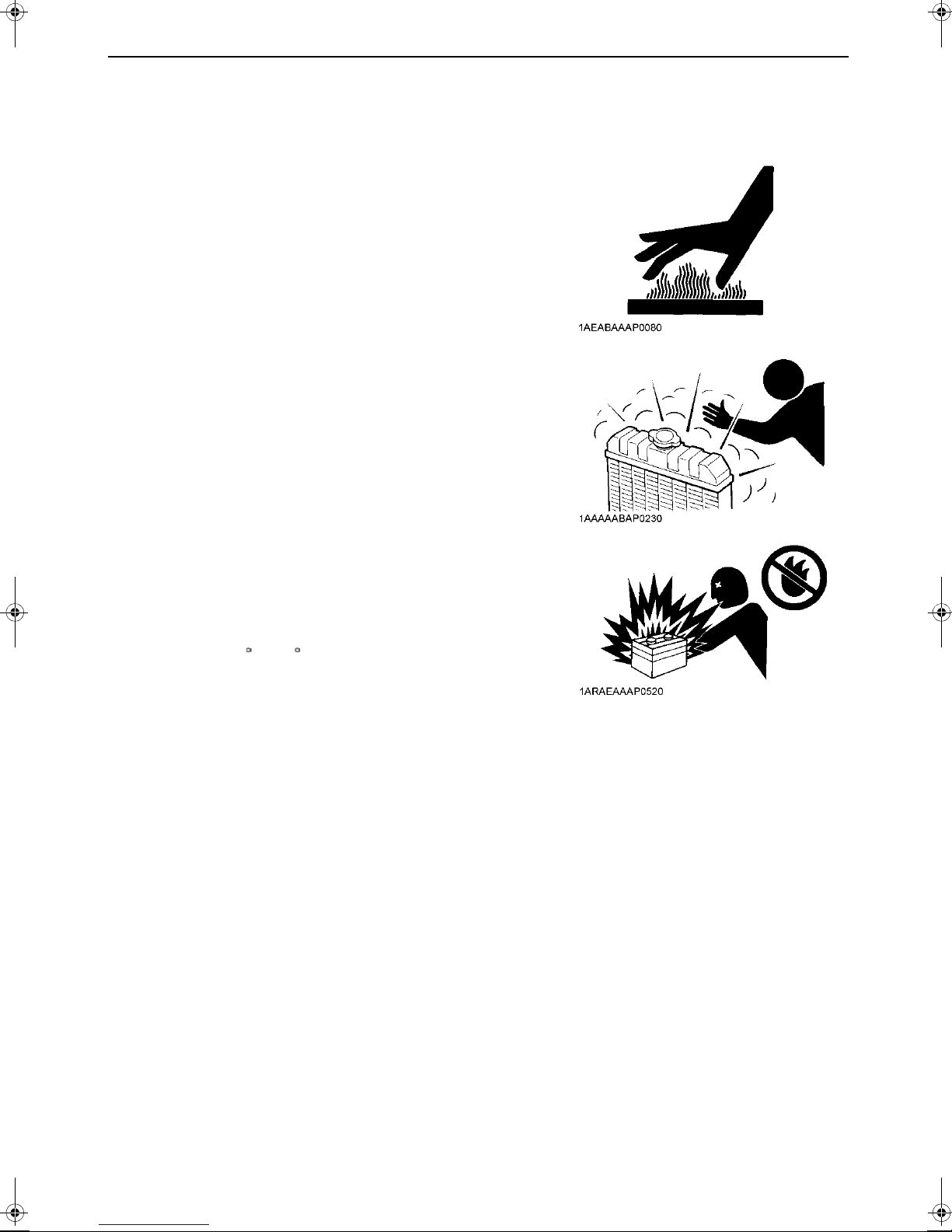
CAUTIONS AGAINST BURNS & BATTERY EXPLOSION
A To avoid burns, be alert for hot components, e.g. muffler,
muffler cover, radiator, pipes, hoses, engine body,
coolant, engine oil, etc. during operation and just after the
engine has been shut off.
A DO NOT remove the radiator cap while the engine is
running or immediately after stopping. Otherwise hot
water from the radiator will escape under pressure
causing injury by scalding. Wait for more than 10 minutes
to allow the coolant to cool down, before removing the
cap.
A Make sure to close the drain valve of coolant and engine
oil, close radiator pressure cap and tighten hose clamps
before operating. If any of these parts are taken off, or left
loose, serious personal injury can result.
A The battery presents an explosive hazard. When the
battery is being activated, hydrogen and oxygen gases
are extremely explosive.
A Keep sparks and open flames away from the battery,
especially when charging the battery. DO NOT strike a
match near the battery.
A DO NOT check battery charge by placing a metal object
across the terminals. Use a voltmeter or hydrometer.
A DO NOT charge battery if frozen, there is a risk of
explosion. When battery is frozen, allow the battery to
warm up to 16 C (61 F) before charging.
A DO NOT use or charge the battery if its fluid level is below
the LOWER (lower limit level) mark (refillable type battery
only).
Otherwise, the component parts may deteriorate earlier
than expected, which may shorten the service life or
cause an explosion. Add distilled water until the fluid level
Page 12
CONDUCTING SAFETY CHECKS & MAINTENANCE
A Know how to stop the generator quickly, and understand
operation of all the controls. DO NOT permit anyone to
operate the generator without proper instruction.
A When checking engine or servicing, place the generator
in an open area and level ground. DO NOT work on
anything that is supported ONLY by lift jacks or a hoist.
Always use blocks or safety stands to support the
generator before servicing.
A Detach the battery from the generator before conducting
service.
Put a “DO NOT OPERATE!” tag on the key switch and
remove the key to avoid accidental starting.
A To avoid sparks from an accidental short circuit, always
disconnect the battery’s ground cable (-) first and
connect it last.
A Sulfuric acid in battery electrolyte is poisonous. It is
strong enough to burn skins and clothing and cause
blindness if splashed into eyes. Keep electrolyte away
from eyes, hands and clothing.
If you spill electrolyte on yourself, flush with water, and
get medical attention immediately.
A Be sure to stop the engine and remove the key when
conducting daily and periodic maintenance, servicing
and cleaning.
A Check or conduct maintenance after the engine, coolant,
muffler, or muffler cover have cooled off completely.
A Always use the appropriate lifting equipment and make
sure safety stands are in good condition when performing
any service work. Make sure that you understand how to
use the equipment before servicing.
A Use ONLY the correct engine flywheel rotating
techniques for manually rotating the engine. DO NOT
attempt to rotate the engine by pulling or prying on the
cooling fan or V-belt. This practice can cause serious
personal injury or premature machine damage to the
cooling fan.
A Replace fuel, lubricant and coolant hoses with their hose
clamps every 2 years or earlier if required. They are
made of rubber and deteriorate over time whether used
or not.
A When servicing is performed together by two or more
persons, take care to perform all work safely.
A Keep first aid kit and fire extinguisher handy at all times.
7SAFE OPERATION
Page 13
SAFE OPERATION8
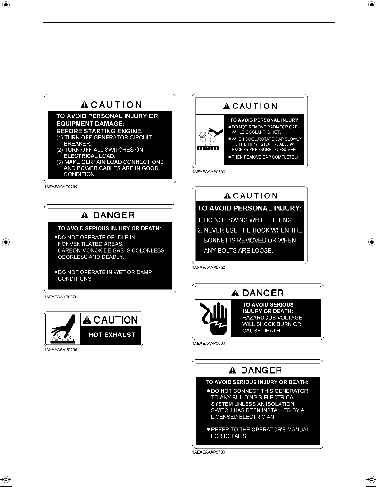
DANGER, WARNING AND CAUTION LABELS
Pay special attention to all labels on the generator.
Refer to following representations for labels used on the SQ-Series Generator. Labels are
available individually from your KUBOTA Dealer.
(1) Part No. G3341-8851-0 (5) Part No. G3907-8832-0
(6) Part No. G3352-8836-0
(2) Part No. G3341-8824-0
(3) Part No. 18620-8806-0
(4) Part No. 18901-5090-0
(7) Part No. G3341-8830-0
(8) Part No. G3341-8831-0
Page 14
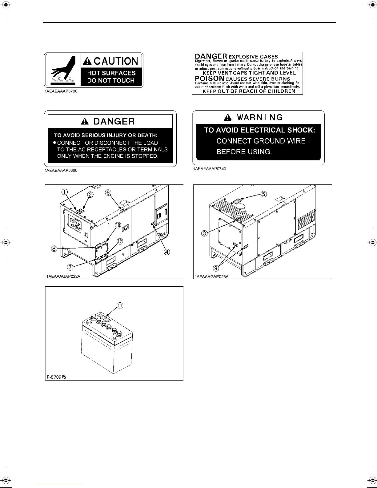
(9) Part No. G3102-8806-0 (11) Part No. 6C090-5896-0
(10) Part No. G3341-8822-0 (12) Part No. G3341-8895-0
9SAFE OPERATION
Page 15

SAFE OPERATION10
CARE OF DANGER, WARNING AND CAUTION LABELS
1. Keep danger, warning and caution labels clean and free from obstructing material.
2. Clean danger, warning and caution labels with soap and water, dry with a soft cloth.
3. Replace damaged or missing danger, warning and caution labels with new labels from your
local KUBOTA Dealer.
4. If a component with danger, warning and caution label(s) affixed is replaced with new part,
make sure new label(s) is (are) attached in the same location(s) as the replaced component.
5. Mount new danger, warning and caution labels by applying on a clean dry surface and
pressing any bubbles to outside edge.
Page 16
SERVICING OF GENERATOR
Your dealer is interested in you r new generator and h as
the desire to help you get the most v alue from it. After
reading this manual thoroughly, you will find that you can
do some of the regul ar maintenance yourself.
However, when in need of parts or major service, be sure
to see your KUBOTA Dealer.
For service, contact the KUBOT A Deal ership from which
you purchased your generator or your local KUBOTA
Dealer.
When in need of parts, be prepar ed to give your dealer
the generator and engine serial numbers.
Locate the serial numbers now and record them in the
space provided below.
Model Serial No.
Generator
Engine
Date of Purchase
Name of Dealer
(To be filled in by purchaser)
1SERVICING OF GENERATOR
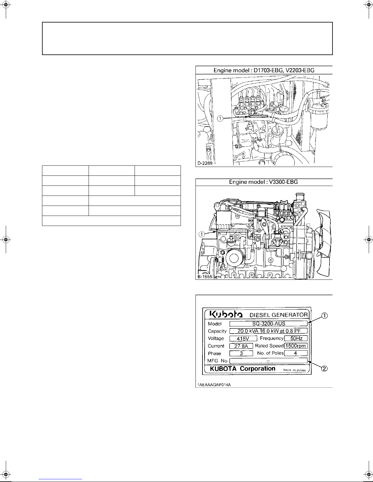
(1) Engine model and serial number
(1) Generator m odel
(2) Generator serial number
Page 17
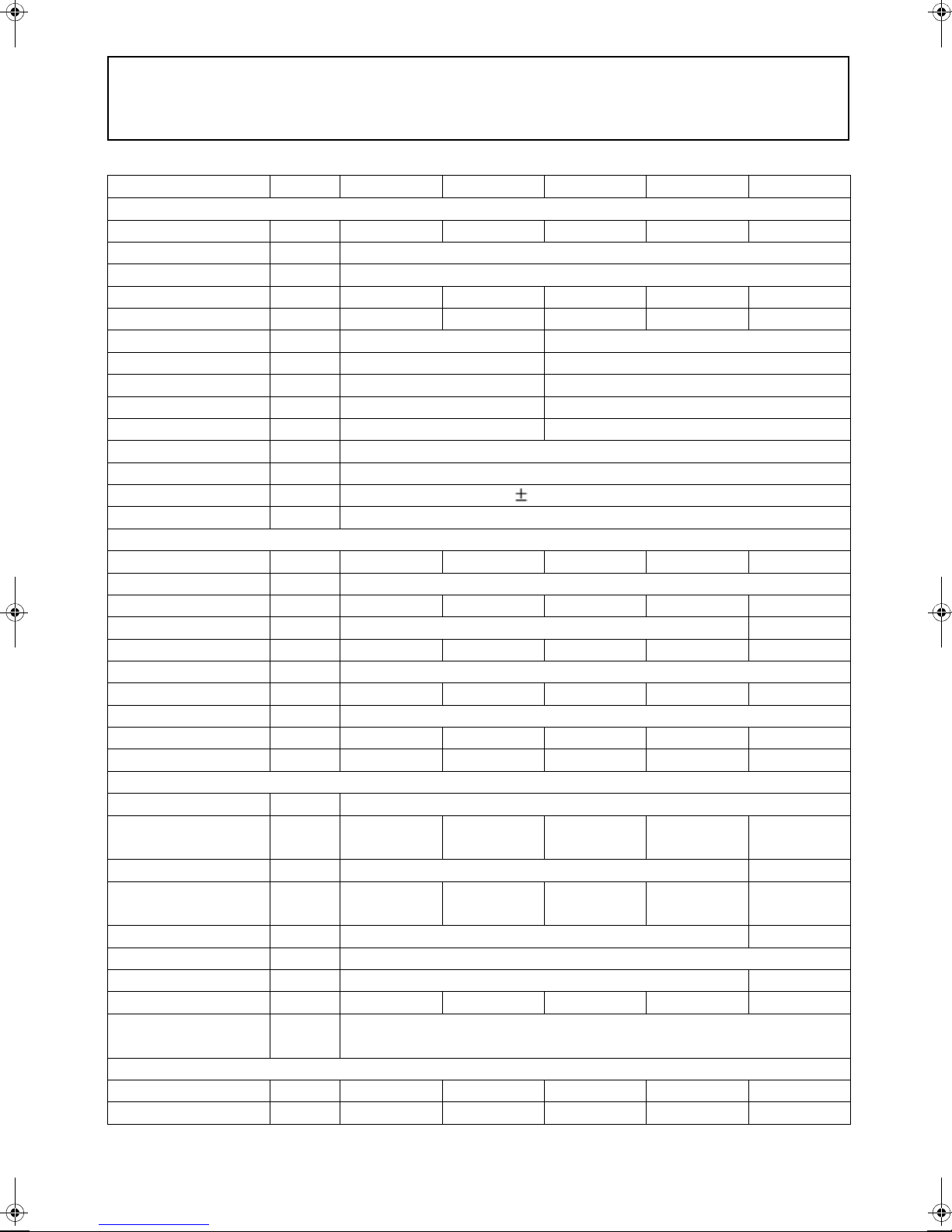
2 SPECIFICATIONS
SPECIFICATIONS
MOKUZIYOU
MODEL Unit SQ-1120 SQ-1150 SQ-3140 SQ-3200 SQ-3300
GENERATOR
Model PX-312KE1 PX-319KE1 PX-312KE3 PX-319KE3 PX-322KE3
Design Revolving field, self-excited brushless AC generator
Frequency Hz 50
Standby Output
Continuous Output
Voltage-single phase V 240 240
Voltage-3 phase V --- 415
Armature connection Series Star with neutral
Phase & Wire 1 Phase & 4 Wires 3 Phase & 12 Wires
Power Factory 1.0 0.8
No. of Poles 4-pole
Insulation Class H
Voltage Regulation %
Type of Coupling Direct coupled
DIESEL ENGINE
Model D1703-EBG V2203-EBG D1703-EBG V2203-EBG V3300-EBG
Type Vertical, water-cooled, 4-cycle diesel engine
No. of cylinders 34344
Bore x Stroke mm 87 x 92.4 98 x 110
Displacement L 1.647 2.197 1.647 2.197 3.318
Engine Speed rpm 1500
Continuous rated output
Lubricating oil API service class CF or higher
Oil capacity L 5.6 7.6 5.6 7.6 13.2
Coolant capacity * L 6.6 7.4 6.6 7.4 9.3
SET
Fuel Diesel fuel No.2 (ASTM D975)
Fuel Consumption
At full load
Fuel tank capacity L 62 68
Continuous operating
hours (at 3/4 load)
kVA (kW)
kVA (kW)
kW (HP)
L/h 3.9 5.5 3.8 5.3 7.7
hrs 20.7 15.1 21.4 15.5 11.5
11.8 (11.8) 16 (16) 15.4 (12.3) 22 (17.6) 33 (26.4)
11.2 (11.2) 15 (15) 14 (11.2) 20 (16) 30 (24)
1.5 (No load to full load)
13.6 (18.2) 18.4 (24.7) 13.6 (18.2) 18.4 (24.7) 26.8 (35.9)
Battery (Ah/5Hr) 80D26R (55Ah)
Starting system Electric
L x W x H mm 1675 x 780 x 1070
Approx. Net Wt. kg 699 762 699 762 935
Emergency stop
system
AMPS
Single phase 240V A 46.7 62.5 12.5 (3 set) 18.1 (3 set) 27.1 (3 set)
Three Phase 415V A --- --- 19.5 27.8 41.7
*Including the recovery tank
130E41R (92Ah)
1935 x 860 x 1095
In case of abnormal : Oil pressure, water temperature, fan belt broken
When the side cover and door open with running
Page 18
3SPECIFICATIONS
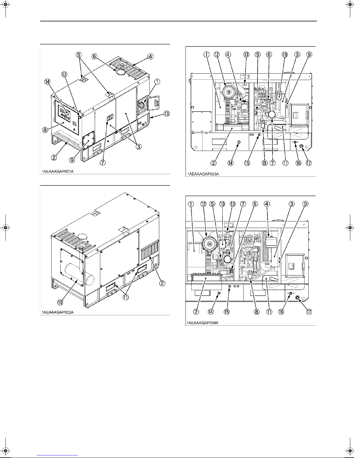
BPart Names
[SQ-1120, SQ-3140, SQ-1150, SQ-3200]
[SQ-3300]
(1) Fuel tank cap-with lockable key
(2) Cooling air inlet
(3) Door
(4) Cooling air outlet
(5) Handling hook
(6) Radiator top cover
(7) Door handle-with lockable key
(8) Panel cover
(9) Load center cover
(10) Muffler
(11) Fork pockets
(12) Emergency stop switch
(13) Fully Bunded (Base bunded to 110% capacity)
(14) Control panel
(1) Generator
(2) Battery
(3) Radiator
(4) Recovery tank
(5) Oil dipstick
(6) Engine oil port
(7) Oil filter cartridg e
(8) Fuel sedimenter cartridge (water separator)
(9) Electric fuel feed pump
(10) Fuel filter cartridge
(11) Fuel tank
(12) Air cleaner
(13) Safety switch
(14) Engine oil drain plug
(15) Coolant drain plug
(16) Fuel tank drain plug
(17) Containment drain point (Plug size: 3/4)
Page 19
4 INSTRUMENT PANEL AND PART NAMES
INSTRUMENT PANEL AND PART NAMES
MOKUJIYOU
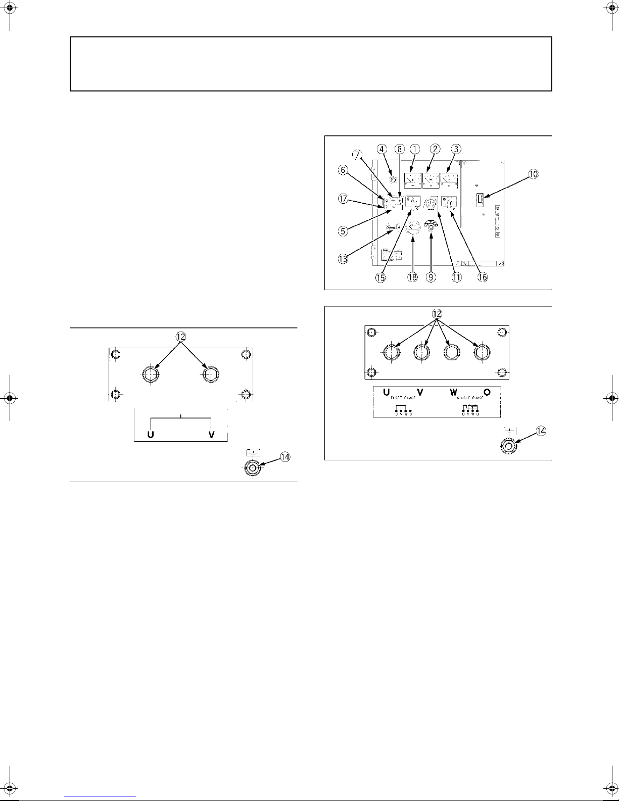
BControl Panel
C 1 Phase Type
[SQ-1120, SQ-1150]
C 3 Phase Type
[SQ-3140, SQ-3200, SQ-3300]
(1) A.C. Voltmeter
(2) Frequency meter
(3) A.C. Ammeter
(4) Pilot lamp (Green lamp)
(5) Glow plug lamp
(6) Water temperature lamp
(7) Oil pressure lamp
(8) Battery charge lamp
(9) Main switch (key)
(10) Circuit breaker
(11) Voltage adjuster
(12) Terminals (output)
(13) Hour meter
(14) Ground terminal
(15) Door open lamp
(16) Fuel gauge
(1) A.C. Voltmeter
(2) Frequency meter
(3) A.C. Ammeter
(4) Pilot lamp (Gree n lamp)
(5) Glow plug lamp
(6) Water temperature lamp
(7) Oil pressure lamp
(8) Battery charge lamp
(9) Main switch (key)
(10) Circuit breaker
(11) Voltage adjuster
(12) Terminals (output)
(13) Hour meter
(14) Ground terminal
(15) Voltmeter change-over switch
(16) Ammeter change-over switch
(17) Door open lamp
(18) Fuel gauge
Page 20

BControl Box
5INSTRUMENT PANEL AND PART NAMES
C 1 Phase Type
C 3 Phase Type
(1) AVR
(Automatic voltage
regulator)
(2) Relay unit
(3) Emergency relay
(4) Starter relay
(5) Solenoid relay
(6) Glow relay
(7) Thermal relay
(Over current relay)
(8) CT
(Current transformer)
(9) Terminal (Generator)
(10) Terminal (AVR)
(11) Terminal (Batte ry) TB3
(12) Terminal
(Main switch) TB2
(13) Terminal
(Auxiliary output) TB1
(14) Terminal
(Auto-start unit) TB4
(15) Fuse (3A, F1)
(16) Fuse (10A, F2)
(17) Fuse (3A, F3)
(18) Fuse (1A, F4)
(19) Fuse (2A, AVR)
Page 21

6 PREPARATION TO SUPPLY THE ELECTRIC POWER
PREPARATION TO SUPPLY THE ELECTRIC POWER
1. Generator grounding
The end user, equipment owner or operator must contact
his local, state, county or municipal electric code
department to determine the approved generator
grounding method to be used in his application or
location.
Recommendations in the NEC (National Electrical Code),
NFPA (National Fire Protection Association),
AUSTRALIAN STANDARDS and OSHA (Occupational
Safety and Health Administration) regulations must be
followed to assure compliance and safe operation.
Always be sure to ground (earth) the generator terminals
to comply with the local, state, national or OSHA
requirements.
One possible connection method for construction site use
is as follows:
(1) Load center cover
(2) Generator ground terminal
(A) #6AWG
Flexible copper ground
connection
(B) Metal ground rod or
building cold water pipe
system per N.E.C. code
Page 22

7PREPARATION TO SUPPLY THE ELECTRIC POWER
AC devices
Electric power (W)
= Voltage (V) Current (A) Power factor
Motor input (kVA)
Motor output (kW)
Motor efficiency power factor
=
2. Recommended capacity of electrical
devices
APPLICATION RANGE
You can operate the SQ-series generator in the following
range.
Typical
Apparatus
SQ-1120
SQ-1150
SQ-3140
SQ-3200
SQ-3300
A Keep an inverter load below 40% of the generator
capacity.
A Keep a mercury lamp l oad below 60% of t he generator
capacity.
A Make sure that tot al active me rcury lamp lo ad is below
30% or so of the generator capacity. Turn on the
mercury lamps one by one. Be careful not to tu rn off
the lamps and on again immedia tely. The generator
voltage may rise to extremely high levels and the AVR
may get damaged.
A Before turning on the lamps again, wait for 10 minutes
or so until the lamps cool down enough.
A The data shown above is only a guideline to
approximate load capacities and may vary from
generator model to generator model, with different
types of loads at rated outputs. These values may be
different from a ct u al ap pl i ca t i ons be c au se of t he in pu t
characteristics peculiar to each load.
Light and
heaters
Commutator
motor
11.2 kVA 7.0 kVA
(11.2 kW)
15.0 kVA
(15.0 kW)
11.2 kVA
(11.2 kW)
16 kVA
(16 kW)
24 kVA
(24 kW)
(5.6 kW)
9.5 kVA
(7.6 kW)
8.5 kVA
(6.8 kW)
12.5 kVA
(10.0 kW)
19.0 kVA
(15.2 kW)
Induction
motor
---
---
5.5 kW (7.5 HP)
3 Phase
7.5 kW (10 HP)
3 Phase
11 kW (15 HP)
3 Phase
A Connecting a motor.
When connecting to a line starting motor, these
generators may be used to start a submerged pump of
5.5kW, 7.5kW, 11.0kW (three phase). When starting
the motor, the voltage drops immediately. The circuit
may be opened if an electromagnetic switch is
connected to the same circuit. When connecting two
motors or more, make sure the total current capacity
of the motors does not exceed the total rated current.
A Connecting to lights and electric heaters.
When connecting to lights or electric heaters, the
generator can be used up to the rated capacity. When
using a single phase, it can be used up to the rated
current.
A Power factor calculation s.
The power factor calculation is used to determine
input of the electrical devices.
Power factors of commonly used devices are listed in the
following table.
Load type Power factor
Single-phase induction motors 0.4 to 0.75
3-phase induction motors 0.65 to 0.85
Electric heaters, incandescent
lamps
Commutator motor 0.8 to 0.95
Fluorescent lamps, mercury
lamps
AC arc welder 0.4 to 0.6
A Ordinarily, a motor is rated in kW. This does not ref er
to motor output.
A If a lighting system is employed together with som e
types of computers and inverter air- conditioners and/
or the regulated power supply for TV sets, the lights
might suffer flickering. This phenomenon does not
indicate a fault of the gen erator: it is caused by poor
matching between the above-mentioned regulated
power supply and the generator's au tomatic voltage
regulator. In such a case, modify the load combination
to eliminate the flickering.
1.0
0.4 to 0.9
Page 23

8 CONNECTING THE LOAD
CONNECTING THE LOAD
MOKUJIYOU
BConnection Notes
BConnecting the Load
To avoid personal injury:
A Before the generator can be
connected to a building’s electrical
system, a licensed electrician must
install an isolation (transfer) switch
in the building’s main fuse box. The
switch is the connection point for
generator power and allows
selection of generator or main line
power to the building. This will
prevent the generator from charging
the main power line (backfeeding)
when the main power supply has
failed or has been turned off for line
repair. Backfeeding can electrocute
or injure line maintenance personn el.
Also, generator and building
electrical system damage can occur
when normal operating power
returns if unit is used without an
isolation switch.
1. Avoid connecting the generator to commercial power
outlet.
2. Avoid connecting the generator in parallel with any
other generator.
To avoid personal injury:
A Connect or disconnect the load to
the AC receptacle only when the
engine is stopped.
1. Turn OFF the circuit breakers on the control panel.
(1) Circuit breaker
2. Connect the load to the A.C. output terminals.
(1) Terminals (output)
3. Finally be sure to close the cover and tighten up the
lock screws.
Page 24

C Single phase 2 terminal s type
Use (U)-(V)
(1) Light
(2) Television
(3) Air conditioner
(4) Electric Drill
(5) Motor Pump
C 3 phase and single phase 4 terminals type
A For 3 phase power source
Use (U)-(V)-(W)
9CONNECTING THE LOAD
(1) Motor
A For single phase power source
Use (O)-(U)
(O)-(V)
(O)-(W)
(1) Electric Drill
(2) Motor Pump
(3) Air conditioner
Page 25

10 PRE-OPERATION CHECK
PRE-OPERATION CHECK
DAILY CHECK
To prevent problems from occurring, it is important to
know the condition of the ge nerator. Always perform the
following check items before starting the generator.
To avoid personal injury:
A Before checking or servicing the
generator, make sure it is on a level
surface with the engine shut off.
C Check items
-Check for oil, fuel and coolant leakage
-Check and drain bunded base as required
-Check cooling air inlet and outlet for obstructio ns or
clogging
-Check radiator fins for clogging
-Check fan belt tension
-Check engine oil level
-Check coolant level
-Check generator grounding
-Refuel
(See "FUEL" in "PERIODIC SERVICE" section.)
-Care of danger, warning and caution labels
(See "DANGER, WARNING AND CAUTION LABELS" in
" SAFE OPERATION" section.)
To avoid personal injury from contact
with moving parts;
A DO NOT open the door or generator
side cover while the engine is
running.
A Do not touch muffler or exhaust
pipes while they are hot; Severe
burns could result.
BHow to Open the Door
Insert the door key and turn clockwise and open the
machine doors. The doors open together on hinges.
The door of the generator is equipped with a safety
switch. Safety switch automatically shuts off the engine
when door is opened.
(1) Door
(2) Safety switch
BBattery
The battery is shipped in dry, ch arged condition without
electrolyte.
The battery must be charged prope rly before using for the
first time.
To avoid the possibility of battery
explosion:
The battery comes in two types:
refillable and non-refillable. For using
the refillable type battery, follow the
instructions below.
A DO NOT use or charge the battery if
the fluid level is below the LOWER
(lower limit level) mark.
Otherwise, the battery component
parts may deteriorate prematurely,
shorten the battery's service life;
which may cause an explosion.
Immediately, add distilled water until
the battery's fluid level comes
somewhere between the UPPER and
LOWER levels.
A Keep all sparks and flames away
from the battery and fuel tank. A
battery, especially when charging,
will give off hydrogen and oxygen
gases which can explode and cause
serious personal injury.
Page 26

1. Remove the vent plugs.
2. Fill cells up to the upper level with electrolyte.
[Specific gravity of sulfuric acid 1.270 to 1.290 (at
20 C=68 F)]
3. Allow the battery to sit for about one hour after filling.
4. If the electrolyte level is dropped, refill with electrolyte
up to the upper level .
5. Replace the vent plugs.
6. Charge the battery at the n ormal chargin g rate of 6.0
amperes.
7. Wash off any electrolyte which may have spilled.
(1) Vent plug opening
(2) Electrolyte level indication tube
(3) Indicated level
A The duration of dry charged efficiency, will decrease in
proportion to the period of time elapsed after shipment
and during storage. To obta in the longest ser vice life
of the battery, it is necessary for the battery to be
charged for a sufficient period of time. Continue to
charge until all cells are gassing freely, and the
voltage and specific gravity reading in all cells remain
constant for 3 or more successive rea dings taken at
30 minute intervals.
A When the battery has been ch ar ged fu lly, t he spe cific
gravity of electr olyte should be 1 .270 to 1.290 (at 20 C
=68 F).
(A) Upper level
(B) Lower level
11PRE-OPERATION CHECK
BCoolant
To avoid personal injury:
A Place the machine on a level surface.
A DO NOT remove the radiator cap
while coolant is hot. When cool,
rotate the radiator cap slowly to the
first stop to allow excess pressure to
escape. Then remove cap
completely.
1. Remove the radiator cap and fill with specified coolant
until the coolant level is just below the port.
2. Fill with coolant to the “FULL” mark on the recovery
tank.
3. Securely tighten radiator cap and recovery tank cap.
A See "RADIATOR" in "PERIODIC SERVICE" section
for changing coolant.
BOpening and Closing of the Fuel Tank Cap
1. Open the tank cap cover, insert the tank cap cover key
and turn clockwise. Then turn the tank cap
counterclockwise to open.
BEngine Oil
The generator has been shipped without engine oil.
Fill with oil to the correct level before attempting to
start the engine.
1. Place the machine on a level surface.
2. Remove the oil cap.
3. Add engine oil of grade CF or high er, up to the uppe r
mark on the oil level gauge.
A See "ENGINE OIL" in "PERIODIC SERVICE" section
for engine oil capacity and checking engine oil level.
There are three types of key. Select the key as necessary.
(1) Key
(2) Fuel tank cap
(3) Tank cap cover
2. To close the tank ca p, turn cl ockwise and t he tank cap
cover key in the opposite direction. Then close the
tank cap cover.
Page 27

PRE-OPERATION CHECK12
BFuel
To avoid personal injury:
A DO NOT refuel when engine is
running or hot.
A Always shut off the engine before
refueling.
A DO NOT overfill fuel system. If any
fuel overflows, wipe it up completely
before starting operation.
A When refueling, keep all flames,
sparks and cigarettes away from
generator.
1. Always fill the fuel through the fuel tank strainer.
2. Make sure that dirt or water does not enter the fuel
tank.
3. Fill with Diesel fuel No.2-D (ASTMD975).
4. Below 0 C (32 F) a mix of No.1-D and No.2-D is
acceptable.
5. Fuel level is read by fuel gauge placed on the control
panel.
Fuel gauge is activate d with the main switch k ey "ON".
A If the fuel tank should empty complete ly causing the
engine to stop, then the fuel system requires air
bleeding after filling the tank and before restarting the
engine.
(See "Air Bleeding the Fuel System" in "PERIODIC
SERVICE" section.)
Page 28

13OPERATING THE GENERATOR
OPERATING THE GENERATOR
SAFETY DEVICES
To avoid personal injury:
A Read " SAFE OPERATION" in the front
of this manual.
A Read the danger, warning and caution
labels located on the generator.
A To avoid the danger of exhaust fume
poisoning, do not operate the en gine in
a closed building without proper
ventilation.
A Always turn OFF the circuit breaker
before starting the generator.
A Turn OFF a ll switches on the electrical
devices.
A Check the wiring and connections of the
electrical devices before starting the
machine.
A DO NOT touch the live parts during
operation.
To avoid serious injury or death:
A DO NOT modify or remove the safety
devices. Unauthorized modification or
removal may affect the function and
safety of the machine, which m ay result
in serious injury or death.
1. The access door are equipped with safety devices to
detect the opening and/or closing condition of door.
2. The door safety switch (2 ) is located on the access
door.
If you turn the key switch to "ON" with the access door
open, the starter of engine will not activate. (While the
fuel pump solenoid can be activated.)
3. Turn the key switch to "OFF" to close the access door
and then restart the engine.
(1) Access door
(2) Safety switch
4. If you open the access door while the engine is
running, the emergency stop system will stop the
engine.
To maintain the battery's life as much as possible, turn
the key switch to "OFF" position.
(For detail on the emergency unit, see "OPE RATION
OF THE EMERGENCY RELAY" on page 38.)
Page 29

OPERATING THE GENERATOR14
STARTING THE ENGINE
To avoid personal injury:
A To prevent contact with live components
or rotating parts, the engine
automatically stops when load center
cover or access door is opened.
A While the load center cover or access
door remains open, the starter will not
activate.
A Be sure to stop the en gine according to
proper procedure before you open the
load center cover or access door.
Otherwise the power supply will be shut
down instantaneously.
A DO NOT apply any tape or anything else
that would keep the safety switch
inactive.
1. Turn OFF all switches on the electrical
devices.
2. Turn OFF the circuit breakers on the
control panel.
3. Ensure that the fuel lever is set to the
"OPEN" Position.
(1) Fuel lever
(2) Water separator
(A) "OPEN"
4. Insert the key into the main switch and
turn it "ON".
5. Check the battery charge lamp and oil
pressure lamp are "ON".
(1) Circuit breaker (A) "OFF"
A For the AUS specifi ed mo dels , also turn OFF th e lo ad
center circuit breaker.
(1) Water temperature lamp
(2) Oil pressure lamp
(3) Battery charge lamp
(4) Door open lamp
A Do not use ether or any starting fluid for starting the
engine, or severe engine damage will occur.
A To protect the battery and the starter, make sure that
the starter is not continuously turned for more than 10
seconds.
A When there is a severe ove rl oad or sh o rt ci rcu i t in th e
wiring of the generator, the circuit breaker turns OFF.
If this happens, eliminate t he cau se and th en tur n t he
circuit breaker ON again.
A The thermal relay do es not work if the battery voltage
falls below the prescribed level, which will detect
overload on the meter. Therefore, be aware of the
battery condition.
Page 30

6. Turn the key to "GLOW" position.
A See "COLD WEATHER STARTING" section as to the
preheating times.
7. Turn the key to the "START" position
and release when the engine starts.
(1) Main switch (Key) ( A) "OFF"
(B) "ON"
(C) "GLOW"
(D) "START"
15OPERATING THE GENERATOR
BWarm-up in Cold Ambient Temperatures
In cold weather, the engine oil may be cold with increased
viscosity. This can delay oil circulation or abnor mally low
oil pressure for some time after engine start-u p. Th is can
result trouble in the lubrication circuit o r damage to the
engine moving parts.
To prevent the above problems, perform the following
instructions:
Warm up the engine at rated revolution w ith no load.
Ambient temperature Warm-up time requirement
Above 0
0 C(32 F) to -10 C(14 F)
Below -10
C
(32 F) At least 10 minutes
10 to 20 minutes
C
(14 F)
More than 20 minutes
10. Check the voltage on the meters.
A Voltage regulation can be achieved by turning the
voltage adjuster in clockwise or counterclockwise
direction.
A Set voltage to the same as the devices being used.
Single Phase Type
A Do not run the starter motor continuously for more
than 10 seconds at a time, or it may damage the
starter. If the engine fa ils to start, wait for about 30
seconds and try again. When the engine starts to
generate electric power, the green lamp will light up.
8. Check to see that the battery charge
lamp, oil pressure lamp and door open
lamp are "OFF".
9. Check the warning lamps.
Whenever the engine stops automatically during
operation, correct the problem before restarting the
engine.
A Be sure to warm up the engine, not only in winter, but
also in warmer seasons. An insuffic iently warmed-up
engine can short en its service life.
(1) Circuit breaker
(2) Voltage adjuster (Potentiometer)
(3) AC Volt meter
3 Phase Type
(A) "ON"
(1) Circuit breaker
(2) Voltage adjuster (Potentiometer)
(3) AC Volt meter
(4) Voltmeter Change-Over switch
(A) "ON"
Page 31

OPERATING THE GENERATOR16
11. Turn ON the circuit breaker on the
control panel.
(1) Circuit breaker (A) "ON"
A For the AUS specifi ed models, turn O N the load cent er
circuit breaker that corresponds to the receptacle
being used.
12. Turn ON the electric al device switc hes
for the connections.
COLD WEATHER STARTING
If the ambient temperature is below * -5 C (23 F) and the
engine is very cold, start it in the following manner:
Take steps (1) through (5) in "STARTING THE E NGI NE "
section.
6. Turn the main switch (key) to the
"GLOW" position until the glow plug
indicator goes off.
A If the ambient temperature is low, the preheating time
will take longer.
A Shown below are the st andard preheating times for
various temperatures. This operation, however, is not
required, when the engine is warmed up.
Ambient temperature Preheating time
Above 10 C (50 F) NO NEED
10 C (50 F) to
-5 C (23 F)
*Below -5 C (23 F)
Limit of continuous use 20 seconds
7. Turn the key to "S T" ("START") positi on
and the engine should start.
Approx. 5 seconds
Approx. 10 seconds
(If the engine fails to start after 10 seco nds, turn off the
key for 30 seconds. Then repeat steps (6) and (7) above.)
A Do not allow the starter motor to run continuously for
more than 10 seconds.
A Be sure to warm up the engine, not only in winter, but
also in warmer seasons. An insufficiently war med-up
engine can shorten its service life.
A When there is possibility of temperature drops below
-15 C (5 F) detach the battery from the machine, and
keep it indoor in a safe area . Reinstalled the battery
before the next operation.
Page 32

17OPERATING THE GENERATOR
STOPPING THE ENGINE
1. Turn OFF all electrical device switches
for connected loads.
A For the AUS models, also turn OFF the load center
circuit breaker.
2. Turn OFF the circuit breakers.
4. Turn the main switch (key) to the "OFF"
position.
(1) Main switch (Ke y ) (A) "OFF"
5. Turn the fuel lever to the "CLOSE"
position.
(1) Circuit breaker (A) "OFF"
3. Allow the engine to run with no load for
about 5 minutes before stopping the
engine completely.
(1) Fuel lever
(2) Filter bowl
(A) "CLOSE"
Page 33

OPERATING THE GENERATOR18
EMERGENCY STOP SWITCH
A If the emergency stop swit ch is pressed, the battery
power is turned off and the engine is interrupted. Do
not press this switch except for an emergency.
(1) Emergency stop switch
1. If anything unusual occu rs, press the switch (1) and
the engine must be stopped immediately.
2. In this case, be sure to turn off the main switch.
3. Rotate the button to reset emergency stop.
Page 34

MAINTENANCE
ANTI-FREEZE & DISPOSAL OF FLUIDS
A DO NOT run the engine with installe d safety guards detached.
A Anti-freeze contains poison. Wear rubber gloves to avoid personal injury.
In case of contact with skin, wash it off immediately.
A DO NOT mix different types of Anti-freeze. The mixture can produce
chemical reaction causing harmful substances. Use approved or genuine
KUBOTA Anti-freeze.
A Be mindful of the environment and the ecology. Before draining any fluids,
find out the correct way of disposing of them. Observe the relevant
environmental protection regulations when dispos ing of oil, fuel, coolant,
filters and batteries.
A When draining fluids from the engine, place a suitable container
underneath the engine body.
A DO NOT pour waste onto the ground , down a drain, or into any water
source.
19MAINTENANCE
To avoid personal injury:
A Be sure to conduct daily checks,
periodic maintenance, refueling or
cleaning on a level surface with the
engine shut off and the key removed.
A Before allowing other people to use
your generator, explain how to
operate, and have them read and
understand this manual before
operation.
A When cleaning any parts, do not use
gasoline. Use a regular cleanser.
A Always use proper tools that are in
good condition. Make sure you
understand how to use them before
performing any service work.
A When installing, be sure to tighten all
nuts and bolts lest they should be
loose. Tighten the nuts and bolts to
the specified torque.
A DO NOT put any tools on the battery,
or battery terminals may short out.
Severe burns or fire could result.
Detach the battery from the engine
before maintenance.
A DO NOT touch muffler or exhaust
pipes while they are hot; severe
burns could result.
Page 35

20 MAINTENANCE
SERVICE INTERVALS
Observe the following for service and maintenance.
Interval
Ref.
page
No.
Check point
First
50
hours
Every
day
Every
100
hours
Every
hours
250
Every
500
hours
1 Check of fuel pipes and clamp bands 2 Check and drain bunded base as required 35
3 Change of engine oil *5 11
4 Cleaning of air cleaner element 31 *1
5 Check of battery electrolyte level 32
6 Check of fan belt tightness 35
7 Check of radiator hoses and clamp bands 30
8 Check of intake air hose 31
9 Replacement of oil filter cartridge 27
Replacement of fuel filter cartridge or element 23,
10
24
11 Cleaning of sedimenter (water separator) 24
12 Cleaning of water jacket (radiator interior) 30
13 Replacement of fan belt 35
14 Check of valve clearance 15 Replacement of air cleaner element 31 *2
Check of damage in electric wiring and loose
16
connections
Check of fuel injection nozzle injection
17
pressure
34
-*3
18 Check of injection pump - *3
19 Replacement of fuel pipes and clamp bands - *3
Replacement of radiator hoses and clamp
20
bands
30
21 Replacement of battery 32
22 Change of radiator coolant (L.L.C.) *5 29
23 Replacement of intake air hose 31 *4
A The jobs indicated by must be done after the first 50 hours of operation.
*1 Air cleaner should be cleaned more often in dusty conditions than in normal conditions.
*2 After 6 times of cleaning.
*3 Consult your local KUBOTA Dealer for this service.
*4 Replace earlier if necessary.
*5 Level check.
A When the battery is used for less than 100 hours in a year, check its electrolyte yearly. (for refillable battery’s only)
Page 36

Interval
No.
Check point
Every
1000
hours
Every
1500
hours
Every
3000
hours
Every
1
year
Every
years
Ref.
page
2
1 Check of fuel pipes and clamp bands 2 Check and drain bunded base as required 35
3 Change of engine oil 11
4 Cleaning of air cleaner element 31 *1
5 Check of battery electrolyte level 32
6 Check of fan belt tightness 35
7 Check of radiator hoses and clamp bands 30
8 Check of intake air hose 31
9 Replacement of oil filter cartridge 27
Replacement of fuel filter cartridge or element 23,
10
24
21MAINTENANCE
11 Cleaning of sedimenter (water separator) 24
12 Cleaning of water jacket (radiator interior) 30
13 Replacement of fan belt 35
14 Check of valve clearance 15 Replacement of air cleaner element 31 *2
Check of damage in electric wiring and loose
16
connections
Check of fuel injection nozzle injection
17
pressure
34
-*3
18 Check of injection pump - *3
19 Replacement of fuel pipes and clamp bands - *3
Replacement of radiator hoses and clamp
20
bands
30
21 Replacement of battery 32
22 Change of radiator coolant (L.L.C.) 29
23 Replacement of intake air hose 31 *4
A The jobs indicated by must be done after the first 50 hours of operation.
*1 Air cleaner should be cleaned more often in dusty conditions than in normal conditions.
*2 After 6 times of cleaning.
*3 Consult your local KUBOTA Dealer for this service.
*4 Replace earlier if necessary.
*5 Level check.
A When the battery is used for less than 100 hours in a year, check its electrolyte yearly. (for refillable battery’s only)
Page 37

22 PERIODIC SERVICE
Model Capacity
SQ-1120, SQ-3140,
[Engine model : D1703-EBG]
SQ-1150, SQ-3200
[Engine model : V2203-EBG]
62
SQ-3300
[Engine model : V3300-EBG]
68
L Fuel tank capacity
PERIODIC SERVICE
FUEL
Fuel is flammable and can be dangerous. You should
handle fuel with care.
To avoid personal injury:
A DO NOT mix gasoline or alcohol with
diesel fuel. This mixture can cause
an explosion.
A Be careful not to spill fuel during
refueling. If fuel should spill, wipe it
off at once, or it may cause a fire.
A Stop the engine before refueling.
Keep the machine away from the fire.
A Be sure to stop the engine while
refueling or bleeding and when
cleaning or changing fuel filter or fuel
pipes. DO NOT smoke when working
around the machine or when
refueling.
A Check the above fuel systems in a
well ventilated and open place.
A When fuel and lubricant are spilled,
refuel after the machine cooled
down.
A Cetane Rating : The minimum recommended Fuel
Cetane Rating is 45. A cetane rating greater th an 50
is preferred, especially for ambient temperatures
below - 20 C (-4 F) or elev atio ns abo ve 15 00 m.
A Diesel Fuel Specification Type and Sulf ur Content %
(ppm) used, must be compliant with all applicable
emission regulations for the area in which the engine
is operated.
A Use of diesel fuel wit h s u lfu r cont e nt les s t ha n 0 . 10 %
(1000 ppm) is strongly recommended.
A If high-sulfur fuel (sulfur content 0.50 % (5000 ppm) to
1.0 % (10000 ppm)) is used as a diesel fuel, change
the engine oil and oil filter at shorter intervals.
(approximately half).
A DO NOT USE Fuels that have sulfur content greater
than 1.0 % (10000 ppm).
A Be sure to use a strainer when filling the fue l tank, or
dirt or sand in the fue l may cause trouble in the f uel
injection pump.
A Always use diesel fuel. Yo u are required not to use
alternative fuel, because its quality is unknown and
affect the generator performance. Kerosene, which is
very low in cetane rating, adversely affects the engine.
Diesel fuel differs in grades depending on the
temperature.
A Be careful not to let the fuel tank become empty, or air
can enter the fuel system, necessitating bleeding
before next engine start.
BFuel Level Check and Refueling
1. Check to see that the fuel level is above the lower limit
of the fuel level gauge.
2. If the fuel is too low, add fuel to the upper limit. Do not
overfill.
A No.2-D is a distillate fuel oil of lower volatility for
engines in industrial and heavy mobile service.
(SAE J313 JUN87)
A Diesel fuels specified to EN 590 or ASTM D975 ar e
recommended.
Page 38

23PERIODIC SERVICE
BAir Bleeding the Fuel System
To avoid personal injury;
A DO NOT bleed a hot engine as this
could cause fuel to spill onto a hot
exhaust manifold creating a danger
of fire.
Air bleeding of the fuel system is required if;
A after the fuel filter and pipes have been detached and
refitted;
A after the fuel tank has become empty; or
A before the engine is to be used after long storage.
[PROCEDURE]
1. Fill the fuel tank with fuel.
2. Set the fuel lever to "OPEN" position.
3. Turn the key to "ON" for 30 to 40 seconds.
BCleaning the Fuel Filter Element
[Engine model : D1703-EBG, V2203-EBG]
Replace the fuel filter element every 500 hours of use,
using the following procedure.
1. Close the fuel filter lever.
(1) Fuel filter lever
(2) Fuel filter pot
2. Remove the top cap, and rinse the inside with diesel
fuel.
3. Take out the element, and replace the element.
4. After cleaning, reinstall the fue l filte r to ke ep du st a nd
dirt out.
5. Air-bleed the fuel line.
6. Properly dispose of used fuel filter element.
(A) "CLOSE"
(B) "OPEN"
(1) Main switch (Key) ( A) "ON"
A With the key switch at "ON", the fuel electro-
mechanical pump can be activated automatically to
vent the air in the fuel pipes, hoses and filter.
A Always turn the key to "OFF" when air is v ented and
the engine is not used, or it will cause the batt ery to
discharge.
A Entrance of dust, water and dirt can cause a
malfunction of the fuel injection pump and the injection
nozzle. Wash the fuel filter cup periodically.
(1) O ring
(2) Filter element
(3) Spring
(4) Filter bowl
(5) Screw ring
Page 39

PERIODIC SERVICE24
BFuel Filter Cartridge Replacement
[Engine model : V3300-EBG]
Replace the fuel filter cartrid ge every 500 hours of use,
using the following procedure.
1. Turn the fuel lever to the "CLOSE" position.
(1) Fuel filter cartridge
(2) O ring
(3) Pipe joint
(4) Cover
(1) Fuel lever
(2) Water separator
(A) "CLOSE"
2. Remove the fuel filter cartridge by using ring spanner.
(1) Fuel filter cartridge (A) "REMOVE"
3. Apply fuel oil thinly over the gasket and tighten the
cartridge into position by hand-tightening only.
4. Air-bleed the fuel line.
5. Properly dispose the used fuel filter cartridge.
BCleaning the Water Separator
(Sedimenter)
A Every 250 hours of operation, clean the fuel filter in a
clean place to prevent dust contamination.
A When the marker com es close to the drain out level,
remove the screw ring and let water flow out of the
filter bowl.
1. Turn the fuel lever to the "CLOSE" position.
(1) Fuel lever
(2) Water separator
(A) "CLOSE"
A Replace the fuel filter cartridge periodically to prevent
wear of the fue l inject ion pu mp plunge r or th e injec tion
nozzle, due to dirt or water in the fuel.
2. Remove the filter bowl, and rinse the inside with diesel
fuel.
3. 3. Take out the element, and rinse it with diesel fuel.
4. After cleaning, reinstall the fuel filter to keep out dust
and dirt.
5. Air-bleed the fuel line.
A Entrance of water, dust and dirt can cause a
malfunction of the fuel injection pump and the injection
nozzle. Wash the fuel filter cup periodically.
Page 40

(1) O ring
(2) Filter element
(3) Spring
(4) Marker
(5) Filter bowl
(6) Screw ring
BDraining Water in the Fuel Tank
If the water separator gets filled too often, let water out of
the fuel tank.
The water in the ta nk can be draine d by openi ng the pl ug,
as shown below illustration.
25PERIODIC SERVICE
ENGINE OIL
To avoid personal injury:
A Be sure to stop the engine before
checking and changing the engine
oil and the oil filter cartridge.
A DO NOT touch muffler or exhaust
pipes while they are hot; severe
burns could result. Always stop the
engine and allow it to cool before
conducting inspections,
maintenance, or cleaning.
A Contact with engine oil can damage
your skin.
Put on gloves when handling engine
oil. If you come in contact with
engine oil, wash it off immediately.
A Be sure to check the engine oil on a level surface. If
placed on gradient s, oi l qua ntit y can n ot b e meas ure d
accurately.
(1) Fuel tank drain plug
(2) Fuel tank cap
A Do not operate a diesel engine when engine oil is
overfilled. This can effect the air intake system which
could result in engine damage or malfunction.
Page 41

PERIODIC SERVICE26
Model Capacity
SQ-1120, SQ-3140
[Engine model : D1703-EGB]
SQ-1150, SQ-3200
[Engine model : V2203-EGB]
SQ-3300
[Engine model : V3300-EGB]
5.6
7.6
13.2
BChecking Oil Level and Adding Engine Oil
1. Check the engine oil level b efore star ting or mor e than
5 minutes after stopping the engine.
2. Remove the oil le vel gaug e, wi pe it c lean and rei nsta ll
it.
3. Take the oil level gauge out again, and check the oil
level.
4. If the oil level is too low, remove the oil port, an d add
new oil to the prescribed level.
5. After adding oil, wait more than 5 minutes a nd check
the oil level again. It takes some time for the oil to drain
down to the oil pan.
6. If the engine is operated with the oil level ne aring the
lower limit, the oil may deterior ate more quickly than
normal, therefor e, ke epi ng the oil leve l ne ar t he up per
limit is recommended.
Engine oil capacity L
A CJ-4 classification oil is intended for use in engines
equipped with DPF (Diesel Particulate Filter) and is
Not Recommended for use in Kubota E3 specification
engines.
A Oil used in the engine should have API clas sification
and Proper SAE Engine Oil Viscosity according to the
ambient temperatures where the engine is operated.
A With strict emission control regulations now in effect,
the CF-4 and CG-4 engine oils have bee n developed
for use with low sulfur fuels, for On-Highwa y vehicle
engines. When a Non-Road engine runs on high sulfur
fuel, it is advisable to use a "CF or better" classification
engine oil with a high Total Base Number (a minimum
TBN of 10 is recommended).
(1) Oil port
(2) Oil level gauge
[Lower end of oil level gauge]
(A) Engine oil level within this
range is proper.
above 25 C (77 F)
0 to 25 C (32 to 77 F)
below 0 C (32 F)
SAE30 or
SAE20 or
SAE10W or
SAE10W-30
SAE10W-40
SAE10W-30
SAE10W-40
SAE10W-30
SAE10W-40
A When using oil of different brands from the previous
one, be sure to drain all the previous oil before adding
the new engine oil.
Page 42

27PERIODIC SERVICE
BChanging Engine Oil
To avoid personal injury:
A Be sure to stop the engine before
draining engine oil.
A When draining engine oil, place a
suitable container underneath the
engine and dispose of it according to
local regulations.
A DO NOT drain oil from a hot engine.
Allow engine to cool down
sufficiently to avoid being burned.
1. Change oil after the initial 50 hours of operation and
every 250 hours thereafter.
2. Remove the drain plug to drain the engine oil. Drain all
the old oil, drains easier and completely when the
engine is warm. Inspect drain plug gasket. Re place if
damaged.
BReplacing the Oil Filter Cartridge
To avoid personal injury:
A Be sure to stop the engine before
changing the oil filter cartridge.
A Allow engine to cool down
sufficiently. Oil can be hot and cause
burns.
1. Replace the oil filter cartridge every 500 hours of
operation.
2. Remove the old oil filter cart ridge with a filter wr ench.
Dispose of filter properly.
3. Apply a film of oil to the gasket of the new cartridge.
4. Screw in the cartridge by hand. When the gasket
contacts the seal surface, tighten the cartrid ge firmly
only by hand. If you tighten the cartridge with a
wrench, it will be tightened too much.
(1) Engine oil drain plug
3. Install the oil drain plug and gasket.
4. Add new engine oil up to the upper line of the oil level
gauge.
(1) Oil filter cartridg e
(2) Remove with a filter wrench
(Tighten with your hand)
(1) Oil filter cartridg e
Page 43

PERIODIC SERVICE28
5. After the new cartridge has been replaced, the engine
oil level normally decreases a little. Th erefore run th e
engine for a while and check for oil leaks through the
seal before checking the engine oil level. Add oil if
necessary.
A Completely wipe off any oil sticking to the machine in
the filter area.
RADIATOR
Make it a rule to check the coolant level before every
operation.
To avoid personal injury:
A DO NOT stop the engine suddenly,
stop it after about 5 minutes of
unloaded idling.
A Work only after letting the engine and
radiator cool off completely (more
than 30 minutes after it has been
stopped).
A DO NOT remove the radiator cap
while coolant is hot. When cool,
rotate cap slowly to the first stop to
allow excess pressure to escape.
Then remove cap completely.
If overheating should occur, steam
gushes out from the radiator or
recovery tank; Allow the engine to
cool before attempting to open the
cap. Severe burns could result.
BChecking Coolant Level, Adding Coolant
1. Remove the radiator cap after the engine has
completely cooled, and check to see that coolant
reaches the supply port.
2. If the radiator is pr ovided with a recovery t ank, ch eck
the coolant level of the recovery tank. When it is
between the "FULL" and "LOW" marks, the coolant
will usually last for one day’s work.
(1) Recovery tank
(2) Cap
3. When the coolant le vel dr ops du e t o eva po r at ion , ad d
only coolant up to the full level.
(A) "FULL"
Upper line 1.1 L
(B) "LOW"
(1) Radiator top cover
(2) Radiator cap
(3) Coolant filling port
Page 44

[Engine model : D1703-EBG, V2203-E BG]
4. Check to see by a drain plug;
it is at the fully bunded as shown below.
(1) Coolant drain plug
(2) Radiator
[Engine model : V3300-EBG]
4. Check to see the two drain points; one is at the
crankcase side and the other is at the fully bunded as
shown below.
29PERIODIC SERVICE
BChanging Coolant
1. To drain coolant, always remove both drain plugs and
simultaneously open the radiator cap as well. With the
radiator cap kept closed, the coolant will not drain
completely. Dispose of used coolant properly.
2. Remove the overflow pipe of the radiator pressure cap
to drain the recovery tank.
3. Prescribed coolant volume
L
Engine model Coolant capacity
D1703-EBG 5.5
V2203-EBG 6.3
V3300-EBG 8.2
4. An improperly tightened radiator cap or a gap between
the cap and the seat increases loss of coolant.
5. Coolant (Radiator cleaner and anti-fr ee ze)
Season
Summer
Winter (When
temperature drops
below 0 C (32 F)) or all
season
Pure water and radiator
cleaner
Pure water and anti-freeze
(See "Anti-freeze" in
"RADIATOR" section.)
Coolant
(1) Coolant drain cock
(2) Coolant drain plug
(3) Radiator
A If the radiator cap has to be removed, proceed with
caution and secure ly retighten the cap.
A If coolant is leaking, consult your local KUBOTA
Dealer.
A Make sure that mudd y or sea wa ter is not us ed i n the
radiator.
A Use clean, fresh water and 50% anti-freeze to fill th e
recovery tank.
A Do not refill recovery tank with coolant over the
"FULL" level mark.
A Be sure to clos e the ra diator c ap se curely. If the cap is
loose or improperly closed, coolant may leak out and
decrease the level quickly.
A When coolant is added, coolant level may drop the
first time the engine is started. Stop the engine, and
add coolant if necessary.
BRemedies for Rapid Coolant Loss
1. Check for dust and dirt betwee n the radiator fins and
cooling tube. Clean the fins and the tubes as if
necessary.
2. Check the tension of the fa n belt. If loose, tighten it
securely.
3. Check the internal blockage in the radiator cooling
tubes. If scale forms in the tubes, clean with the scale
inhibitor or its equivalent.
Page 45

PERIODIC SERVICE30
BChecking Radiator Hoses and Clamps
To avoid personal injury:
A Be sure to check radiator hoses and
hose clamps periodically. If radiator
hoses are damaged or coolant leaks
out, overheating can occur.
Check to see if radiator h oses are properly fixed every
250 hours of operation or 6 months, whichever comes
first.
1. If hose clamps are loose or water leaks, tig hten hose
clamps securely.
2. Replace hoses and hose clamps if rad i ato r hoses ar e
swollen, hardened or cracked.
Replace hoses and hose clamps every 2 years, or earlier
as required, if hoses are found to be swollen, hardened or
cracked.
(1) Radiator hose
(2) Hose clamp
BPrecaution Overheating
Take the following actions in the event the coolant
temperature is nearly or more than the boiling point,
which is called "Precaution overheating". Take these
actions if the engine’s the alarm lamp lights up.
1. Turn off all output circuit breakers and keep the engine
running without load.
2. Do not stop the engine suddenly. Stop it after about 5
minutes of unloaded idling.
3. If the engine stops within about 5 minutes of running
under no load, immediately leave an d keep yourself
away from the machine. Do not open the hood and
any other part.
4. Keep yourself and othe rs well away from the engine
for an additional 10 minutes or while the steam
continues to blow out.
5. Checking that there is no danger of being burned
eliminate the causes of overheating according to the
manual, see "TROUBLESHOOTING" section. And
then restart the engine.
BCleaning Radiator Core (outside)
If dust is between the fin and tube, wash it away with
running water.
A Do not clean radiator with firm tools such as spatulas
or screwdrivers. They may damage the delicate fins or
tubes. It can cause coolant lea ks o r d ecr ease cooling
performance.
A Be careful to keep water off of electrical parts.
BCleaning the Radiator (inside)
1. Clean up the coolant line inside in the following cases.
A As per the SERVICE INTERVALS list.
A When changing the coolant.
2. Use a radiator cleaning agent. This helps wash
away scale deposits.
BAnti-freeze
To avoid personal injury:
A When using anti-freeze, put on some
protection such as rubber gloves
(Anti-freeze contains poison.).
A If should drink anti -freeze, throw up
at once and take medical attention.
A When anti-freeze comes in contact
with the skin or clothing, wash it off
immediately.
A Do not mix different types of anti-
freeze. The mixture can produce
chemical reaction causing harmful
substances.
A Anti-freeze is extremely flammable
and explosive under certain
conditions. Keep fire and children
away from anti-freeze.
A When draining fluids from the
engine, place some container
underneath the engine body.
A Do not pour waste onto the grounds,
down a drain, or into any water
source.
A Also, observe the relevant
environmental protection
regulations when disposing of antifreeze.
Always use a 50/ 50 mix of l ong-li fe co olant and c lean so ft
water in KUBOTA engines.
Contact KUBOTA concerning coolant for extreme
conditions.
1. Long-life coolant (hereafter LLC) comes in several
types. Use ethylene glycol (EG) type for this engine.
Page 46

31PERIODIC SERVICE
2. Before employing LLC-mixed cooling wate r, flush the
radiator with fresh water. Repeat this procedure 2 or 3
times to clean up the radiator and engine block from
inside.
3. Mixing the LLC
Premix 50% LLC with 50% clean soft water. When
mixing, stir it up well, and then fill into the radiator.
4. The procedure for the mixing of water and anti-freeze
differs according to the make of the anti-freeze. Refer
to SAE J1034 standard, mo re sp ecif ica lly al so to SAE
J814c.
Vol %
Anti-freeze
Freezing Point Boiling Point*
CFCF
50 -37 -34 108 226
*
At 1.013 x 10 Pa (760 mmHg) pressure (atmospheric)
A higher boiling point is obtained by using a r adiator
pressure cap which permits the development of
pressure within the cooling system.
5. Adding the LLC
(1) Add only water if the coolant level reduces in the
cooling system by evaporation.
(2) If there is a coolant leak, add the LLC of the same
manufacturer and type in the same coolant
percentage.
*Never add any long-life coolant of different
manufacturer. (Different brands may have different
additive components, and the engine may fail to
perform as specified.)
6. When the LLC is mixed, do no t employ any radiator
cleaning agent. Th e LLC contains anticorros ive agent.
If mixed with the cleaning agent, sludge may build up,
adversely affecting the engine parts.
7. Kubota's genuine long-life coolant has a service life of
2 years. Be sure to change the coolant every 2 years.
A The above data represent industry standards that
necessitate minimum glycol content in the
concentrated anti-freeze.
[Engine model : D1703-EBG, V2203-EBG]
5. Replace the element every year or every 6 cleanings.
.
(1) Air cleaner body
(2) Element
(3) Wing bolt
(4) Evacuator valve
A Make sure the wing bolt for the element is tight
enough. If it is loo se, dust and dir t may be suck ed into
the engine, causing premature wearing down the
cylinder liner and piston ring earlier, and thereby
resulting in poor power output and need for engine
repair.
[Engine model : V3300-EBG]
If the air cleaner is equipped with the secondary element,
start it in the following manner :
Take steps (1) through (4) foregoing.
5. Replace the primary e lement every year or every 6
cleanings. If the primary element is heavily stained,
replace it sooner. At this time, also replace the
secondary element.
6. The secondary element should be removed only if it is
to be replaced.
7. To protect the engine, d o not remove the secondary
element in normal servicing of the primary element.
AIR CLEANER
Since the air cleaner employed on this engine is a dry
type, never apply oil to it.
1. Open the evacuator valve once a week under ordinary
conditions - or daily when used in severe or dusty
conditions. This will get rid of large particles of du st
and dirt.
2. Wipe the inside air cleaner clean with cloth if it is dirty
or wet.
3. Avoid touching the element except when cleaning.
4. When dry dust adheres to the element, blow
compressed air from the inside turning the element.
Pressure of compressed air must be unde r 205 kPa
(2.1 kgf/cm , 30 psi).
(1) Air cleaner body
(2) Cover
(3) Secondary element
(4) Primary element
(5) Evacuator valve
Page 47

PERIODIC SERVICE32
A Make sure hooking clip is tight enough. If it is loose,
dust and dirt may be sucked into the eng ine, causin g
excessive wear or premature engine failure and need
for engine repair.
BCleaning Primary Air Filter Element
1. To clean the element, use clean dry compressed air
on the inside of the element.
Air pressure at the nozzle must not exce ed 205 kPa
(2.1 kgf/cm , 30 psi).
Maintain reasonable distance between the nozzle and
filter.
BEvacuator Valve
Open the evacuator valve once a week under ordinary
conditions - or daily when used in dusty condition - to get
rid of large particles of dust and dirt.
A If the dust cup is mounted incorrectly, dust or dirt will
not collect in the cup and allow the dust to co me into
direct contact with the element an d thus require the
element be replaced prematurely.
BATTERY
To avoid personal injury:
A Be careful not to let the battery
electrolyte contact your body or
clothing.
A Wear eye protection and rubber
gloves, since the diluted sulfuric acid
solution burns skin and eyes, and
eats holes in clothing. Should this
occur, immediately wash it off with
running water and get medical
attention.
Mishandling of the battery shortens the service life and
adds to maintenance costs. Obtain the maximum
performance and the longest life of the battery by
handling properly and with care.
Engine starting will be difficult, if the battery charge is low.
Be sure to keep the battery in a fully charged state for best
performance and battery life.
BBattery Charging
(1) Air cleaner body
(2) Secondary element
(3) Primary element
(4) Dust cup
(5) "TOP" mark
(6) Evacuator valve
BFor the Air Cleaner with a Dust Cup
Remove and clean out the dust cup once a week un der
normal conditions or daily in extreme conditions.
Do not allow the dust cup to fill above half way regardless
of conditions.
Install the air cleaner dust cup with "TOP" indicated on the
rear of the cup in the upward position with hor izontally
mounted air cleaner bodies or vertically mounted air
cleaner bodies, the cup may be mounted in any direction.
To avoid the possibility of battery
explosion:
The batteries come in two types:
refillable and non-refillable. For using
the refillable type battery, follow the
instructions below.
A DO NOT use or charge the battery if
the fluid level is below the LOWER
(lower limit level) mark.
Otherwise, the battery component
parts may deteriorate prematurely,
which will shorten the battery’s
service life or may cause an
explosion.
Immediately, add distilled water until
the battery’s fluid level comes
somewhere between the UPPER and
LOWER levels.
A When the battery is being activated,
hydrogen and oxygen gases in the
battery are extremely explosive.
Keep open sparks and flames away
from the battery at all times,
especially when charging the
battery.
Page 48

A When charging the battery, ensure
the vent caps are securely in place (if
equipped).
A When disconnecting the cable from
the battery, start with the negative
terminal, and when connecting them,
start with the positive terminal first.
A DO NOT check the battery charge by
placing a metal object across the
terminals. Use a voltmeter or
hydrometer.
1. Make sure that each electrolyte level is to the bottom
of vent wells, if necessary, add only distilled water in a
well-ventilated place.
33PERIODIC SERVICE
(1) Battery electrolyte level (A) "TOO LOW"
(B) "PROPER"
(C) "TOO HIGH"
2. To slow charge the battery, connect the charger
positive terminal to the battery positive terminal, and
the negative to the negative, then recharge in the
normal manner.
3. Quick recharging charges the battery at a high rate in
a short time. This is only for emergencies.
4. Recharge the battery as ea rly as possible, or battery
life will be extremely shortened.
5. When exchanging an old battery for a new one, use a
battery of equal specifications shown in page 2.
(1) Thick cable red (+)
(2) Battery case
(3) Negative / ground cable black (-)
(4) Plug
A Connect the charger positive termina l to the battery
positive terminal, and negative to the negative.
A When disconnecting the cable from the batte ry, start
with the negative terminal first.
When connecting the cable to the b attery, start with
the positive terminal first.
If reversed, the contact of t ools on the battery may
cause a shortage.
(A) "HIGHEST LEVEL"
(B) "LOWEST LEVEL"
Page 49

PERIODIC SERVICE34
BInstructions for Long Term Storage
1. When storing the generator fo r long periods of time,
remove the battery, adjust the electrolyte to the proper
level, and store in a dry and dark place.
2. The battery naturally discharges while it is stored.
Recharge it once a month in summer, and every 2
months in winter.
6. Clamp the other cable to the negative (black, (-) or
neg.) terminal of the helper battery.
7. Clamp the other end to the engi ne block or frame of
the generator as far from the dead battery as possible.
8. Start the disabled generator.
9. disconnect the jumper cables in the exact reverse
order of attachment. (Steps 7, 6 and 5).
10.Remove and discard the damp rags.
BBattery Boost Starting
To avoid serious personal injury.
A Battery gases can explode. Keep
cigarettes, sparks, and flames away
from battery.
A If generator battery is frozen, do not
battery boost start engine.
A DO NOT connect other end of
negative (-) jumper cable to negative
(-) terminal of generator battery.
When battery boost starting engine, follow the
instructions below to safely start the engine.
1. Bring helper batter y of the same voltage as disabled
generator within easy cable reach.
2. Put on safety goggles and rubber gloves.
3. Ensure the vent caps are securely in place. (if
equipped)
4. Cover vent caps w it h da mp r ag s. Do no t a ll ow t he r ag
to touch the battery terminals.
5. Attach the red clamp to th e positive (red, (+) or pos.)
terminal of the dead battery and clamp the other end
of the same cable to the positive (red, (+) or pos.)
terminal of the helper battery.
A This machine has a 12 volt negative (-) ground starting
system.
A Use only same voltage for jump starting.
A Use of a higher voltage source on generators
electrical system could result in severe damage to
generators electrical system.
ELECTRIC WIRING
To avoid personal injury:
Shorting of electric cable or wiring may
cause a fire.
A Check to see if electric cables and
wiring are swollen, hardened or
cracked.
A Keep dust and water away from all
power connections.
Loose wiring and terminal parts
make bad connections, be sure to
repair them before starting the
engine.
Damaged wiring reduces the capacity of electrical parts.
Change or repair damaged wiring immediately.
(1) Dead battery
(2) Lay a damp rag over vent caps.
(3) Jumper cables
(4) Engine block or frame
(5) Helper battery
(A) Connect cables in numerical order.
Disconnect in reverse order after use.
Page 50

35PERIODIC SERVICE
FAN BELT
BAdjusting Fan Belt Tension
To avoid personal injury:
A Be sure to stop the engine and
remove the key before checking the
belt tension.
A Be sure to reinstall the detached
safety shield after maintenance or
checking.
[Engine model : D1703-EBG, V2203-E BG]
Proper fan belt
tension
[Engine model : V3300-EBG]
Proper fan belt
tension
A deflection of between 7 to 9 mm
when the belt is pressed in the
middle or the span.
A deflection of between 10 to 12 mm
when the belt is pressed in the
middle of the span.
FULLY BUNDED
A Before installing the unit all environmental factors
must be considered.
Generator installation must comply with local building
codes, fire regulations and environmental
requirements.
Use these instructions as a general guide only, t he
complete installation must comply with all local, state,
and federal building codes, fire ordinances, and any
other applicable regulations.
1. Open the access door and check for anything unusual
every workday.
2. Look at the point (1) to make sure anything
accumulated will not spill out.
3. If an accumulation may co me ou t, lo ose n the plug (3)
to drain the unit.
4. Finally, retighten up the plug.
1. Stop the engine and remove the key.
2. Apply moderate thumb pressure to belt between
pulleys.
3. If tension is incorrect, loosen the alternator mounting
bolts and, using a l ever p lace d bet wee n the a lt ernat or
and the engine block, pull the alterna tor out until the
deflection of the belt falls within acceptable limits.
4. Replace fan belt if it is damaged.
A If belt is loosen or damage d and the fan is dama ged,
it could result in overheating or insufficient char ging.
Adjust correctly or replace the belt.
(1) Check point
(2) Fully bunded (Base bunded to 110% capacity)
(3) Containment drain point (Plug size: 3/4)
L
Engine model Fully bunded capacity
D1703-EBG, V2203-EBG 84
V3300-EBG 104
(1) Fan belt
(2) Bolt and nut
[D1703-EBG, V2203-EBG]
(A) 7 to 9 mm (under load of 98 N)
[V3300-EBG]
(A) 10 to 12 mm (under load of 64 N)
Page 51

36 TRANSPORTING / STORAGE
TRANSPORTING / STORAGE
MOKUJIYOU
BTransporting
BLifting Procedure
To avoid personal injury:
A Secure the generator to prevent
movement during operation.
A DO NOT stand near or under the
generator while it is suspended.
A The generator is heavy. Utilize
suitable equipment to lift and
transport. Keep hands and feet away
from under the suspended
generator.
A When transporting the generator,
remove the (-) battery cable, close
the fuel cock lever, and keep the
generator level to prevent fuel
spillage.
1. When transporting the generator, use only suitable
transporting equipment, such as crane, fork lift or etc.
2. The generator is equipped with the 2 inlets in the
machine bed for forklift forks. Transportability is
increased by 2 ways; special forklift openings and 1point lifting hook.
Use lifting equipment of sufficient capacity.
To avoid personal injury:
A Use hangers and wire ropes which
are strong enough to withstand the
weight of the machine.
A The apex of the wire rope (distance
"A") must be a minimum of 127 cm.
Or use a spreader bar.
A DO NOT swing while lifting.
A DO NOT use the hook when the
bonnet is removed or when any bolts
are loose.
When lifting the generator for loading it onto a truck or a
ship, follow the method shown below.
Model Approx. gross wt. kg
SQ-1120, SQ-3140 759
SQ-1150, SQ-3200 854
SQ-3300 1015
(1) Wire Rope
(2) Fork pockets
(A) Minimum of 127 cm
Page 52

BStorage
To avoid personal injury:
A DO NOT clean the machine with
engine running.
A To avoid the danger of exhaust fume
poisoning, do not operate the engine
in a closed building without proper
ventilation.
A When storing the generator just after
running, let the engine cool off.
Before storing the generator for more than a few months,
remove any dirt on the machine, and:
1. Remove dirty engine coolant, fill with new coolant and
run the engine for about 5 minutes.
When coolant is added, coolant level dr ops the first
time the engine is started, sto p the engine and add
more coolant.
2. Remove dirty engine oil, fill with new oil and ru n the
engine for about 5 minutes to let the oil penetrate to all
the parts.
3. Check all the bolts an d n ut s, an d ti g ht en i f ne ces sa ry .
4. Remove the battery from the generator, adjust the
electrolyte level , and recharge it. Stor e the b attery in a
dry and dark place.
5. When the engine is not used for a long period of time,
run it for about 5 minutes un der no load every 2 to 3
months to keep it fr ee fr om ru st. If th e eng ine i s stor ed
without any runnin g, moistur e in the air may condens e
into dew over the sliding parts of the engine, resulting
in rust.
6. If you forget to run the engine for longer than 5 to 6
months, apply enough engine oil to the valve guide
and valve stem seal and make sure the valves work
smoothly before starting the engine.
7. Store the generato r in a flat place a nd remove the key.
8. Do not store the generator in a place where fl ammable
materials such as dry grass or straw are present.
9. When covering the gener ator for storage, let engine
and muffler cool off completely.
10.Operate the engine after checking and repairing
damaged wiring or pipes, and clearing flammable
materials carried by rodents, insects or birds.
37TRANSPORTING / STORAGE
Page 53

38 OPERATION OF THE EMERGENCY RELAY
OPERATION OF THE EMERGENCY RELAY
MOKUJIYOU
The SQ series generator is equipped with an emergency unit (EG-20) that is designed to detect trouble and stop the engine
automatically.
1. What to detect
Trouble Detection Method
Oil pressure fall
Water temperature rise
Belt broken
Load center cover or door
open
Oil pressure switch
(ON at below 49 kpa (7 psi))
Water temperature switch
(ON at above 115 3 C (239 5 F))
Voltage of alternator terminal L
(Charge lamp ON: Stop or trouble)
(Charge lamp OFF : Normal)
Safety switch
(ON : Open)
(OFF : Closed)
*The oil pressure switch stays ON after the start
delay period.
*The water temperature switch stays ON after
the start delay period.
*The alternator terminal L stays at "L" after the
start delay period.
*The door limit switch comes ON when the key
switch is set from "START" to "ON" position at
starting.
(*The door limit switch is located on the load
center cover and on the access door.
*The door limit switch is activated when the load
center cover or the access door is opened.)
Start-up delay time
A All the alarms but the doo r-related one are ke pt inactive for a certa in period of time (7 to 14 seconds) af ter the key
switch is set from "START" to "ON" position.
Start delay period.
This interval is necessary to prevent the engine from shutting down while oil pressure is still low after engine start-up.
2. Method at start-up
1. Set the key switch to "ON" position, and the electric fuel feed pump turns ON.
2. Set the key switch to "GLOW" position, and the solenoid turns ON.
3. Set the key switch to "START" position, and the starter is activated. Turn it back to "ON" position, and the emergency
unit starts automatic detecting.
A If the starter is activated b ut the engine fails t o star t, the oil pre ssure switch stays ON. If the key switch is turn ed and
left at "ON" position in this state, the solenoid and fuel electric feed pump will turn OFF after the start delay period. To
have the engine restarted, turn the key switch back to "OFF" position again.
3. Method with an alarm
1. If any of the warning lamps is ON, turn OFF the solenoid and electric fuel feed pump and the engine stops.
2. To restart the engi ne, turn the key switch back to "OFF" position then start again.
A When this device stops the engine, it may be that a malfunction and some minor damage to the engine has occurred.
To limit engine damage as much as possible , please do not m ake the assump tion that shut d own was a false alarm.
Check unit thoroughly prior to restarting.
A Be sure to turn the key switch back to "OFF" position, or the battery will be dead.
Page 54

39OPERATION OF THE EMERGENCY RELAY
4. Alarms and Corrective Measures
If a trouble occurs during op eration, a corresp onding indicator lam p lights up and the engine stops. Deter mine at which
lamp is ON, and pinp oint and correct the cause of trouble.
(1) Water temperature lamp
Lights up if the engine is overheating.
(2) Oil pressure lamp
Lights up if engine oil pressure is too low.
(3) Battery charge lamp
Lights up if there is a battery problem or if the belt is broken.
(4) Access door open lamp
Lights up if the load center cover or the access door is opened.
Light-up Possible Causes Countermeasures
Engine overheating. *See "Precaution Overheating" in
"PERIODIC SERVICE" section. (See page 30.)
Lamp (1)
Lamp (2)
Lamp (3)
Lamp (4)
Water temperature sensor faulty. *Replace the water temperature sensor.
Water temperature sensor wiring faulty. *Repair the wiring.
Insufficient engine oil. *Add engine oil.
Lubricating system in trouble. *Check the system.
Oil pressure sensor faulty. *Replace the sensor.
Oil pressure sensor wiring faulty. *Repair the wiring.
Fan belt loose or damaged. *Readjust belt tension or replace the belt.
Alternator terminal in poor contact. *Connect tightly.
Alternator problem. *Check the alternator.
Access door opened. *Close the door.
Limit switch faulty. *Replace the limit switch.
Limit switch wiring faulty. *Repair the wiring.
Page 55

40 TROUBLESHOOTING
TROUBLESHOOTING
MOKUJIYOU
If the engine does not function properly, use the following chart to identify and correct the cause.
BWhen it is Difficult to Start the Engine
Cause Countermeasures
*Check the fuel tank and fuel filter.
Remove water, dirt and other
impurities.
Fuel is thick and
doesn't flow.
Air or water
mixed in fuel
system.
Thick carbon
deposits on
orifice of
injection nozzle.
Valve clearance
is wrong.
Leaking valves *Grind valves.
Fuel injection
timing is wrong.
Engine oil
becomes thick
in cold weather
and engine
cranks slow.
*As all fuel will be filtered by the filter,
if there should be water or other
foreign matters on the filter, clean th e
filter with kerosene or replace the
filter.
*If air is in the fuel filter or injection
lines, the fuel pump will not work
properly. To attain proper fuel
injection pressure, check carefully for
loosened fuel line coupling, cap nut
and etc.
*Loosen joint bolt atop fuel filter and
air vent screws of fuel injection pump
to eliminate all the air in the fuel
system.
*This is caused when water or dirt is
mixed in the fuel. Clean the nozzle
injection piece, being careful not to
damage the orifice.
*Check to see if nozzle is working
properly or not. If not, install a new
nozzle.
*[Engine model : D1703-EBG,
V2203-EBG]
Adjust valve clearance to 0.18 to
0.22 mm when the engine is cold.
[Engine model : V3300-EBG]
Adjust valve clearance to 0.23 to
0.27 mm when the engine is cold.
*Adjust injection timing
*[Engine model : D1703-EBG]
The injection ti min g 15 .5 before top
dead center.
[Engine model : V2203-EBG]
The injection ti min g 17 .0 before top
dead center.
[Engine model : V3300-EBG]
The injection ti min g 10 .0 before top
dead center.
*Change grade of oil according to the
weather (temperature).
Cause Countermeasures
*Bad valve or excessive wear of
Low
compression
Battery is
discharged and
the engine will
not crank.
A If the cause of troub le cannot be foun d, contact your
local KUBOTA Dealer.
rings, pistons and liners cause
insufficient compression.
Replace with new parts.
*Charge battery.
*In winter, always remove battery
from machine, charge fully and keep
indoors.
Install in machine at time of use.
BWhen Starter does not Start
Cause Countermeasures
Emergency
switch "ON"
Battery
discharges too
much
Access door is
opened.
Defect of
contact point or
shortage of
alternator Lshaped coupler
Alternator defect *Replace.
Fuse blows. *Replace.
*Rotate button to reset emergency
stop.
*Recharge battery.
*Close the door.
*Check wiring and repair.
Page 56

BWhen Output is Insufficient BWhen Engine Suddenly Stops
41TROUBLESHOOTING
Cause Countermeasures
*Clean orifice and needle valve,
Carbon stuck
around orifice of
nozzle piece
Compression is
insufficient.
Leaking valves
Fuel is
insufficient.
Overheating of
moving parts
Valve clearance
is wrong.
Air cleaner is
dirty
Fuel injection
pressure is
wrong.
Injection pump
wear
being very careful not to damage
the nozzle orifice.
*Check nozzle to see if good. If not,
replace with new parts.
*Bad valve and excessive wear of
rings, pistons and liners cause
insufficient compression. Replace
with new parts.
*Grind valves.
*Check fuel system.
*Check lubricating oil system.
*Check to see if lubricating oil filter is
working properly.
*Filter element deposited with
impurities would cause poor
lubrication. Change element.
*Check that bearing clearances are
within factory specs.
*Check injection timing.
[Engine model : D1703-EBG,
V2203-EBG]
*Adjust valve clearance to 0.18 to
0.22 mm with the eng ine is cold.
[Engine model : V3300-EBG]
*Adjust valve clearance to 0.23 to
0.27 mm with the eng ine is cold.
*Clean the element every 250 hours
of operation.
*Adjust to proper pressure.
13.7 Mpa (140 kgf/cm , 1991 psi)
*Do not use poor quality fuel as it will
cause wear of the pump.
Only use No.2-D diesel fuel.
*Check the fuel injec tion pump
element and delivery valve assembly
and replace as necessary.
Cause Countermeasures
*Check the fuel tank and refill the
Lack of fuel
Bad nozzle
Moving parts
are overheated
due to shortage
of lubrication oil
or improper
lubrication.
fuel, if necessary.
*Also check the fue l system for ai r or
leaks.
*If necessary, replace with a new
nozzle.
*Check amount of engine oil with oil
level gauge.
*Check lubricating oil system.
*At every second oil change, oil filter
cartridge should be replaced.
*Check to see if the engine bearing
clearances are within factory specs.
BWhen Color of Exhaust Smoke is Black
and Excessive
Cause Countermeasures
Fuel governing
device bad
Fuel is of
extremely poor
quality.
Nozzle is bad.
Combustion is
incomplete.
Engine is
operating in
overload
condition.
*Contact dealer for repairs.
*Select good quality fuel.
Use No.2-D diesel fuel only.
*If necessary, replace with new
nozzle.
*Cause is poor atomization, improper
injection timing, etc.
Because of trouble in injection
system or in poor valve adjustment,
or compression
leakage, poor compression, etc.
Check for the cause.
*Diagnose and eliminate reason for
overload.
Page 57

TROUBLESHOOTING42
B When Engine must be Stopped
Immediately
Cause Countermeasures
Engine
revolution
suddenly
decreases or
increases.
Unusual sound
is heard
suddenly.
Color of exhaust
suddenly turns
dark.
Bearing parts
are overheated.
Oil lamp lights
up during
operation.
*Check the adjustments, injection
timing and the fuel system.
*Check all moving parts carefully.
*Check the fuel injection system,
especially the fuel injection nozzle.
*Check for overload condition.
*Check the lubricating system.
*Check the lubricating system.
*Check, if the engine bearing
clearances are within factory specs.
*Check the function of the relieve
valve in the lubricating system.
*Check pressure switch.
*Check filter base gasket.
BWhen Engine Overheats
Cause Countermeasures
Engine oil
insufficient
Fan belt broken
or elongated
Coolant
insufficient
Excessive
concentration of
antifreeze
Radiator net or
radiator fin
clogged with
dust
Inside of
radiator or
coolant flow
route corroded
Fan or radiator
or radiator cap
defective
Thermostat
defective
Temperature
gauge or sensor
defective
Overload
running
Head gasket
defective or
water leakage
Incorrect
injection timing
Unsuitable fuel
used
*Check oil level. Replenish oil as
required.
*Check all moving parts carefully.
*Replenish coolant.
*Add water only or change to coo lant
with the specified mixing ratio.
*Clean net or fin carefully.
*Clean or replace radiator and parts.
*Replace defective parts.
*Check thermostat and replace if
necessary.
*Check temperature with
thermometer and replace if
necessary.
*Reduce load.
*Replace parts.
*Adjust to proper timing.
*Use the specified fuel.
Page 58

BGenerator Troubleshooting
Trouble Possible causes Correction
Single-phase load applied beyond allowable
level (on three phase models).
Unusual noise or vibration
Frame overheated.
Voltage failure to rise.
Voltage too high.
Voltage hunting
Circuit breaker turned OFF.
Pilot lamp failure to light up
Bearing deteriorated. *Replace the bearing.
Coupling damaged. *Replace the coupling.
Cooling fan inlet or outlet blocked. *Unblock the inlet or outlet.
Voltage too high. *Readjust the voltage.
Overloaded. *Reduce the load.
Voltage maladjusted. *Readjust using the voltage control.
AVR excitation output cable broken. *Repair the cable.
AVR itself in trouble. *Replace the AVR.
Exciter's winding short-circuited or broken. *Replace the generator.
AVR excitation input cable broken. *Repair the cable.
Generator's winding broken. *Replace the generator.
AVR excitation output fuse blown out. *Replace the fuse.
Voltage maladjusted. *Readjust using the voltage control.
AVR voltage detection cable broken. *Repair the cable.
AVR itself in trouble. *Replace the AVR.
Mercury arc lamp or such conductive load
connected.
Inverter or such switching load connected. *Disconnect such load.
AVR itself in trouble. *Replace the AVR.
Connected cable or load short-circuited.
Overloaded. *Reduce the load.
Lamp bulb broken. *Replace the bulb.
Generator voltage too low. *See "Voltage failure to rise" above.
43TROUBLESHOOTING
*Lower the load to acceptable level.
*Disconnect such load.
*Contact a qualifi ed electrical engineer for
inspection.
Page 59

TROUBLESHOOTING44
Page 60

WIRING DIAGRAM 45
WIRING DIAGRAM
Page 61

WIRING DIAGRAM46
Page 62

WIRING DIAGRAM 47
Page 63

WIRING DIAGRAM48
 Loading...