

Kubota SM-E3B Series, Z602-E2B, D662-E2B, Z482-E2B, D902-E2B Workshop Manual
...
WORKSHOP MANUAL
KiSC issued 03, 2011 A
DIESEL ENGINE
SM-E3B SERIES

TO THE READER
KiSC issued 03, 2011 A
This Workshop Manual has been prepared to provide servicing personnel with
information on the mechanism, service and maintenance of SM-E3B series. It is divided
into three parts, “General”, “Mechanism” and “Servicing”.
Q General
Information on the engine identification, the general precautions, maintenance check
list, check and maintenance and special tools are described.
Q Mechanism
Information on the construction and function are included. This part should be
understood before proceeding with troubleshooting, disassembling and servicing.
Refer to Diesel Engine Mechanism Workshop Manual (Code No. 9Y021-01876) for
the one which has not been described to this workshop manual.
Q Servicing
Information on the troubleshooting, servicing specification lists, tightening torque,
checking and adjusting, disassembling and assembling, and servicing which cover
procedures, precautions, factory specifications and allowable limits.
All information illustrations and specifications contained in this manual are based on
the latest product information available at the time of publication.
The right is reserved to make changes in all information at any time without notice.
Due to covering many models of this manual, information or picture being used have
not been specified as one model.
© KUBOTA Corporation 2007
March 2007
SM-E3B SERIES WSM
SAFETY FIRST
KiSC issued 03, 2011 A
SAFETY INSTRUCTIONS
SAFETY INSTRUCTIONS
This symbol, the industry’s “Safety Alert Symbol”, is used throughout this manual and on labels on
the machine itself to warn of the possibility of personal injury. Read these instructions carefully.
It is essential that you read the instructions and safety regulations before you attempt to repair or use
this unit.
DANGER : Indicates an imminently hazardous situation which, if not avoided, will result in
death or serious injury.
WARNING : Indicates a potentially hazardous situation which, if not avoided, could result in
death or serious injury.
CAUTION : Indicates a potentially hazardous situation which, if not avoided, may result in
minor or moderate injury.
Q IMPORTANT : Indicates that equipment or property damage could result if instructions are not
followed.
Q NOTE : Gives helpful information.
BEFORE SERVICING AND REPAIRING
• Read all instructions and safety instructions in this
manual and on your engine safety decals.
• Clean the work area and engine.
• Park the machine on a firm and level ground.
• Allow the engine to cool before proceeding.
• Stop the engine, and remove the key.
• Disconnect the battery negative cable.
• Hang a “DO NOT OPERATE” tag in operator
station.
1

SM-E3B SERIES WSM
KiSC issued 03, 2011 A
SAFETY INSTRUCTIONS
SAFETY STARTING
• Do not start the engine by shorting across starter
terminals or bypassing the safety start switch.
• Unauthorized modifications to the engine may impair
the function and / or safety and affect engine life.
SAFETY WORKING
• Do not work on the machine while under the influence
of alcohol, medication, or other substances or while
fatigued.
• Wear close fitting clothing and safety equipment
appropriate to the job.
• Use tools appropriate to the work. Makeshift tools,
parts, and procedures are not recommended.
• When servicing is performed together by two or more
persons, take care to perform all work safely.
• Do not touch the rotating or hot parts while the engine
is running.
• Never remove the radiator cap while the engine is
running, or immediately after stopping. Otherwise, hot
water will spout out from radiator. Only remove
radiator cap when cool enough to touch with bare
hands. Slowly loosen the cap to first stop to relieve
pressure before removing completely.
• Escaping fluid (fuel or hydraulic oil) under pressure
can penetrate the skin causing serious injury. Relieve
pressure before disconnecting hydraulic or fuel lines.
Tighten all connections before applying pressure.
• Wear a suitable hearing protective device such as
earmuffs or earplugs to protect against objectionable
or uncomfortable loud noises.
• Do not open high-pressure fuel system.
High-pressure fluid remaining in fuel lines can cause
serious injury. Do not disconnect or attempt repair or
fuel lines, sensors, or any other components between
the high-pressure fuel pump and injectors on engines
with high pressure common rail fuel system.
• High voltage exceeding 100 V is generated in the
ECU, and is applied to the injector.
Pay sufficient caution to electric shock when
performing work activities.
2
SM-E3B SERIES WSM
KiSC issued 03, 2011 A
SAFETY INSTRUCTIONS
AVOID FIRES
• Fuel is extremely flammable and explosive under
certain conditions. Do not smoke or allow flames or
sparks in your working area.
• To avoid sparks from an accidental short circuit,
always disconnect the battery negative cable first and
connect it last.
• Battery gas can explode. Keep sparks and open
flame away from the top of battery, especially when
charging the battery.
• Make sure that no fuel has been spilled on the engine.
VENTILATE WORK AREA
• If the engine must be running to do some work, make
sure the area is well ventilated. Never run the engine
in a closed area. The exhaust gas contains poisonous
carbon monoxide.
DISPOSE OF FLUIDS PROPERLY
• Do not pour fluids into the ground, down a drain, or
into a stream, pond, or lake. Observe relevant
environmental protection regulations when disposing
of oil, fuel, coolant, electrolyte and other harmful
waste.
PREVENT ACID BURNS
• Sulfuric acid in battery electrolyte is poisonous. It is
strong enough to burn skin, clothing and cause
blindness if splashed into eyes. Keep electrolyte
away from eyes, hands and clothing. If you spill
electrolyte on yourself, flush with water, and get
medical attention immediately.
3
SM-E3B SERIES WSM
KiSC issued 03, 2011 A
SAFETY INSTRUCTIONS
PREPARE FOR EMERGENCIES
• Keep a first aid kit and fire extinguisher handy at all
times.
• Keep emergency numbers for doctors, ambulance
service, hospital and fire department near your
telephone.
4
SM-E3B SERIES WSM
KiSC issued 03, 2011 A
SPECIFICATIONS
SPECIFICATIONS
Model Z482-E3B Z602-E3B
Number of Cylinders 2
Type Vertical, Water-cooled, 4 cycle IDI diesel engine
Bore × Stroke 67.0 × 68.0 mm (2.64 × 2.68 in.) 72.0 × 73.6 mm (2.83 × 2.90 in.)
Total Displacement 479.0 cm
ISO Net Continous
ISO / SAE Net Intermittent
SAE Gross Intermittent
8.10 kW / 3600 min
(10.9 HP / 3600 min
9.30 kW / 3600 min
(12.5 HP / 3600 min
9.90 kW / 3600 min
(13.3 HP / 3600 min
Maximum Bare Speed 3800 min
Minimum Bare Idling Speed 900 to 1000 min
Combustion Chamber Spherical type (E-TVCS)
Fuel Injection Pump Bosch MD type mini pump
Governor All speed mechanical governor
Direction of Rotation Counter-clockwise (viewed from flywheel side)
Injection Nozzle Bosch “Throttle” type
Injection Timing 0.37 rad (21 °) before T.D.C. 0.35 rad (20 °) before T.D.C.
Firing Order 1-2
Injection Pressure 13.73 MPa (140.0 kgf/cm
Compression Ratio 23.5 : 1 24 : 1
Lubricating System Forced lubrication by trochoid pump
Oil Pressure Indicating Electrical type switch
Lubricating Filter Full flow paper filter (Cartridge type)
Cooling System Pressurized radiator, forced circulation with water pump (not included in the basic engine)
Starting System Electric Starting with Starter
Starting Motor 12 V, 0.8 kW 12 V, 1.0 kW
Starting Support Device By glow plug in combustion chamber
EGR None
Battery 12 V, 28 AH equivalent 12 V, 36 AH equivalent
Charging Alternator 12 V, 150 W 12 V, 480 W
Fuel Diesel Fuel No.2-D (ASTM D975)
Lubricating Oil
Oil Pan Depth
Lubricating Oil
Capacity
101 mm (3.98 in.)
Oil Pan Depth
121 mm (4.76 in.)
Weight (Dry) kg (lbs) 53.1 (117) 60.0 (132)
* The specification described above is of the standard engine of each model.
* Conversion Formula : HP = 0.746 kW, PS = 0.7355 kW
3
(29.23 cu.in.) 599.0 cm3 (36.55 cu.in.)
-1
(rpm)
-1
(rpm))
-1
(rpm)
-1
(rpm))
-1
(rpm)
-1
(rpm))
-1
(rpm)
10.1 kW / 3600 min
(13.5 HP / 3600 min
11.6 kW / 3600 min
(15.5 HP / 3600 min
12.5 kW / 3600 min
(16.8 HP / 3600 min
-1
(rpm)
2
, 1991 psi)
-1
( rpm)
-1
(rpm))
-1
( rpm)
-1
(rpm))
-1
( rpm)
-1
(rpm))
Class CF lubricating oil as per API classification is recommended.
For details on recommended lubricating oils, see page G-6, 9
2.1 L (0.55 U.S.gals) 2.5 L (0.66 U.S.gals)
2.5 L (0.66 U.S.gals) –
W10336300
5

SM-E3B SERIES WSM
KiSC issued 03, 2011 A
SPECIFICATIONS
Model D722-E3B D782-E3B D902-E3B
Number of Cylinders 3
Type Vertical, Water-cooled, 4 cycle IDI diesel engine
Bore × Strok e
Total Displacement 719.0 cm
ISO Net Continuous
ISO / SAE Net Intermittent
SAE Gross Intermittent
Maximum Bare Speed 3800 min
67.0 × 68.0 mm
(2.64 × 2.68 in.)
3
(43.88 cu.in.) 778.0 cm3 (47.48 cu.in.) 898.0 cm3 (54.80 cu.in.)
12.0 kW / 3600 min
(16.4 HP / 3600 min
14.0 kW / 3600 min
(18.8 HP / 3600 min
14.9 kW / 3600 min
(20.0 HP / 3600 min
-1
(rpm) 3450 min-1 (rpm) 3800 min-1 (rpm)
-1
(rpm)
-1
(rpm))
-1
(rpm)
-1
(rpm))
-1
(rpm)
-1
(rpm))
Minimum Bare Idling Speed 900 to 1000 min
67.0 × 73.6 mm
(2.64 × 2.90 in.)
11.7 kW / 3200 min
(15.7 HP / 3200 min
13.5 kW / 3200 min
(18.1 HP / 3200 min
14.1 kW / 3200 min
(18.9 HP / 3200 min
-1
-1
-1
-1
-1
-1
-1
(rpm)
(rpm)
(rpm))
(rpm)
(rpm))
(rpm)
(rpm))
72.0 × 73.6 mm
(2.83 × 2.90 in.)
15.2 kW / 3600 min
(20.4 HP / 3600 min
17.5 kW / 3600 min
(23.5 HP / 3600 min
18.5 kW / 3600 min
(24.8 HP / 3600 min
-1
(rpm)
-1
(rpm))
-1
(rpm)
-1
(rpm))
-1
(rpm)
-1
(rpm))
Combustion Chamber Spherical type (E-TVCS)
Fuel Injection Pump Bosch MD type mini pump
Governor All speed mechanical governor
Direction of Rotation Counter-clockwise (viewed from flywheel side)
Injection Nozzle Bosch “Throttle” type
Injection Timing 0.37 rad (21 °) before T.D.C. 0.30 rad (17 °) before T.D.C. 0.35 rad (20 °) before T.D.C.
Firing Order 1-2-3
2
Injection Pressure 13.73 MPa (140.0 kgf/cm
, 1991 psi)
Compression Ratio 23.5 : 1 24 : 1
Lubricating System Forced lubrication by trochoid pump
Oil Pressure Indicating Electrical type switch
Lubricating Filter Full flow paper filter (Cartridge type)
Cooling System Pressurized radiator, forced circulation with water pump (not included in the basic engine)
Starting System Electric Starting with Starter
Starting Motor 12 V, 0.8 kW 12 V, 1.0 kW 12 V, 1.2 kW
Starting Support Device By glow plug in combustion chamber
EGR None
Battery 12 V, 36 AH equivalent 12 V, 52 AH equivalent
Charging Alternator 12 V, 150 W 12 V, 480 W
Fuel Diesel Fuel No.2-D (ASTM D975)
Lubricating Oil
Lubricating Oil
Capacity
Oil Pan Depth
101 mm (3.98 in.)
Oil Pan Depth
121 mm (4.76 in.)
3.2 L (0.85 U.S.gals) – 3.7 L (0.98 U.S.gals)
3.8 L (1.0 U.S.gals) 3.6 L (0.95 U.S.gals) –
Class CF lubricating oil as per API classification is recommended.
For details on recommended lubricating oils, see page G-6, 9
Weight (Dry) kg (lbs) 63.0 (139) 63.5 (140) 72.0 (159)
* The specification described above is of the standard engine of each model.
* Conversion Formula : HP = 0.746 kW, PS = 0.7355 kW
W10304910
6
SM-E3B SERIES WSM
KiSC issued 03, 2011 A
PERFORMANCE CURVES
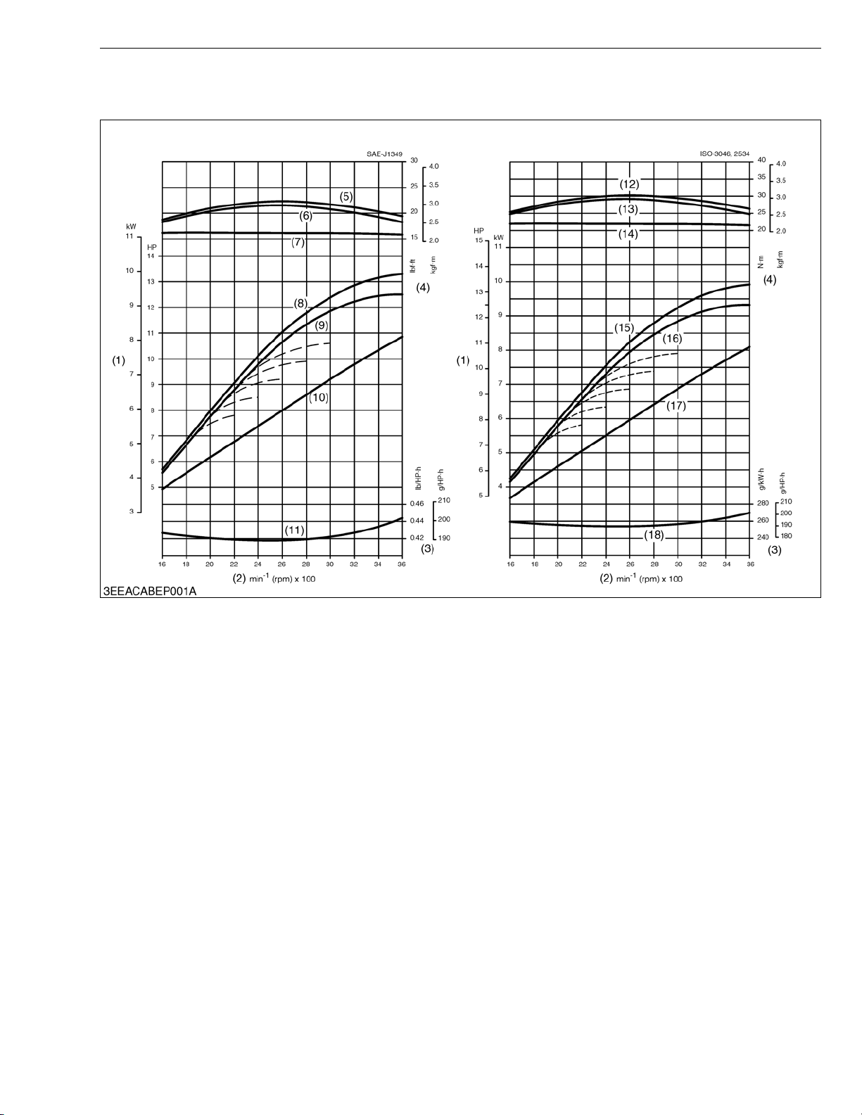
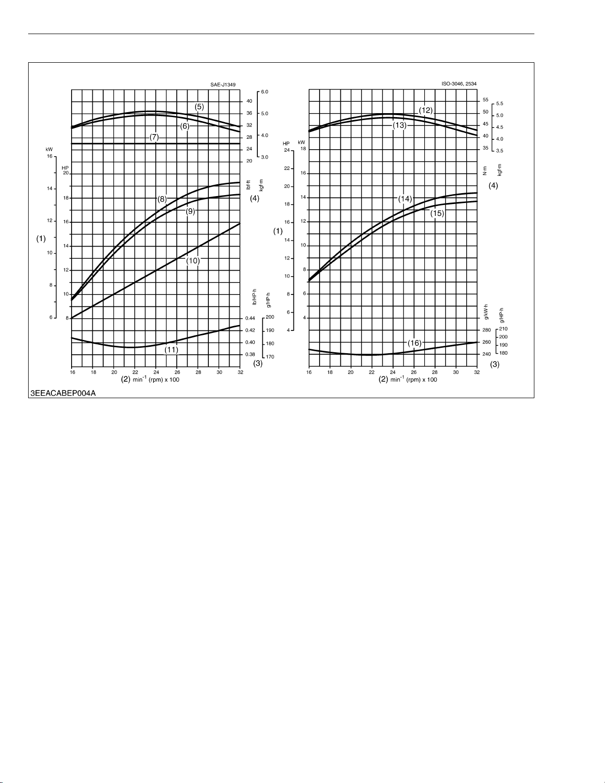
Q Z482-E3B
PERFORMANCE CURVES
(1) Brake Horsepower
(2) Engine Speed
(3) B.S.F.C.
(4) Torque
(5) Gross Intermittent Torque
(6) Net Intermittent Torque
(7) Net Continuous Torque
(8) Gross Intermittent B.H.P.
(9) Net Intermittent B.H.P.
(10) Net Continuous B.H.P.
(11) Net Intermittent B.S.F.C.
(12) Gross Torque
(13) Overload Torque
(14) Continuous Torque
(15) Gross B.H.P.
(16) Overload B.H.P.
(17) Continuous B.H.P.
(18) Overload B.S.F.C.
7
SM-E3B SERIES WSM
KiSC issued 03, 2011 A
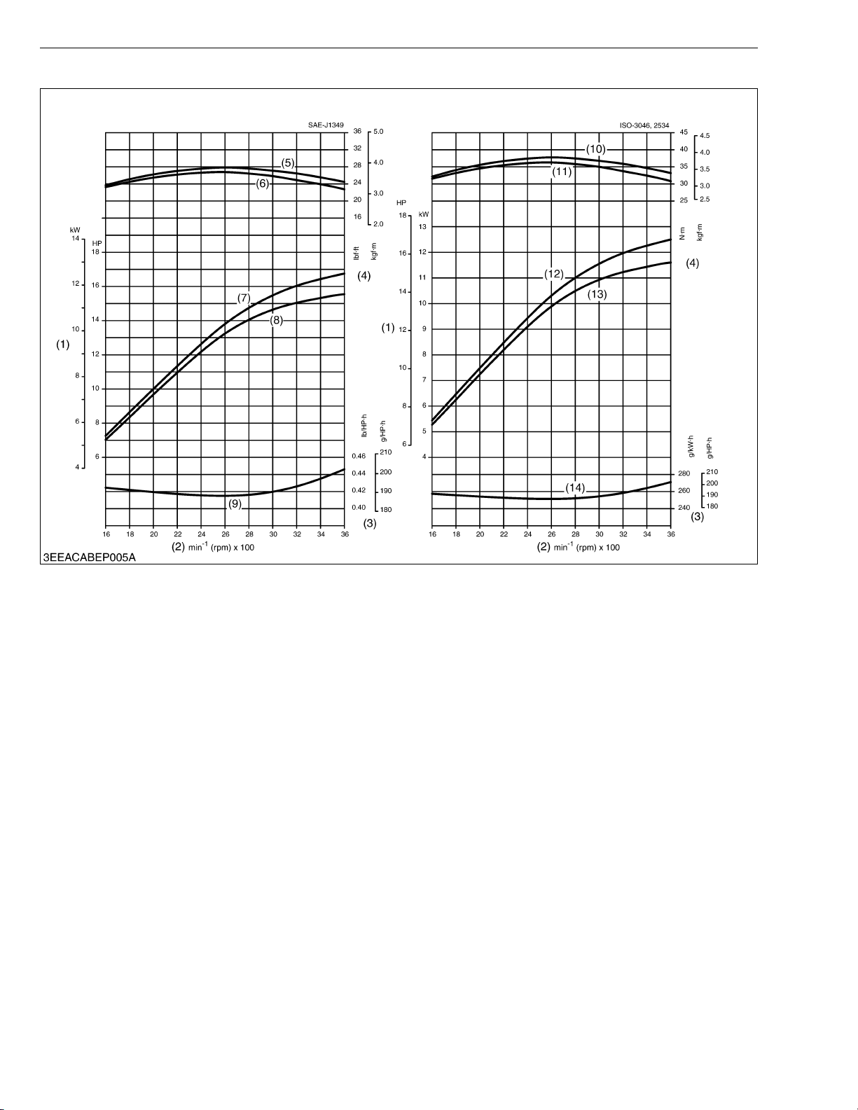
Q Z602-E3B
PERFORMANCE CURVES
(1) Brake Horsepower
(2) Engine Speed
(3) B.S.F.C.
(4) Torque
(5) Gross Intermittent Torque
(6) Net Intermittent Torque
(7) Gross Intermittent B.H.P.
(8) Net Intermittent B.H.P.
(9) Net Intermittent B.S.F.C.
(10) Gross Torque
(11) Overload Torque
(12) Gross B.H.P.
(13) Overload B.H.P.
(14) Overload B.S.F.C.
8
SM-E3B SERIES WSM
KiSC issued 03, 2011 A
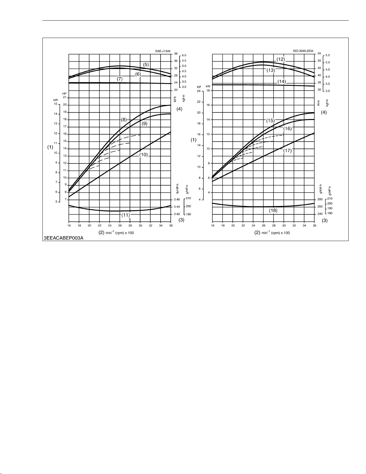
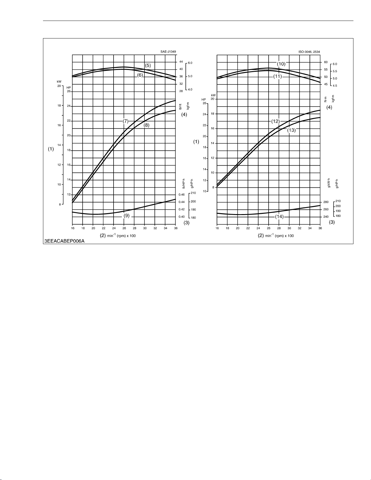
Q D722-E3B
PERFORMANCE CURVES
(1) Brake Horsepower
(2) Engine Speed
(3) B.S.F.C.
(4) Torque
(5) Gross Intermittent Torque
(6) Net Intermittent Torque
(7) Net Continuous Torque
(8) Gross Intermittent B.H.P.
(9) Net Intermittent B.H.P.
(10) Net Continuous B.H.P.
(11) Net Intermittent B.S.F.C.
(12) Gross Torque
(13) Overload Torque
(14) Continuous Torque
(15) Gross B.H.P.
(16) Overload B.H.P.
(17) Continuous B.H.P.
(18) Overload B.S.F.C.
9
SM-E3B SERIES WSM
KiSC issued 03, 2011 A
Q D782-E3B
PERFORMANCE CURVES
(1) Brake Horsepower
(2) Engine Speed
(3) B.S.F.C.
(4) Torque
(5) Gross Intermittent Torque
(6) Net Intermittent Torque
(7) Net Continuous Torque
(8) Gross Intermittent B.H.P.
(9) Net Intermittent B.H.P.
(10) Net Continuous B.H.P.
(11) Net Intermittent B.S.F.C.
(12) Gross Torque
(13) Overload Torque
(14) Gross B.H.P.
(15) Overload B.H.P.
(16) Overload B.S.F.C.
10
SM-E3B SERIES WSM
KiSC issued 03, 2011 A
Q D902-E3B
PERFORMANCE CURVES
(1) Brake Horsepower
(2) Engine Speed
(3) B.S.F.C.
(4) Torque
(5) Gross Intermittent Torque
(6) Net Intermittent Torque
(7) Gross Intermittent B.H.P.
(8) Net Intermittent B.H.P.
(9) Net Intermittent B.S.F.C.
(10) Gross Torque
(11) Overload Torque
(12) Gross B.H.P.
(13) Overload B.H.P.
(14) Overload B.S.F.C.
11
SM-E3B SERIES WSM
KiSC issued 03, 2011 A
DIMENSIONS
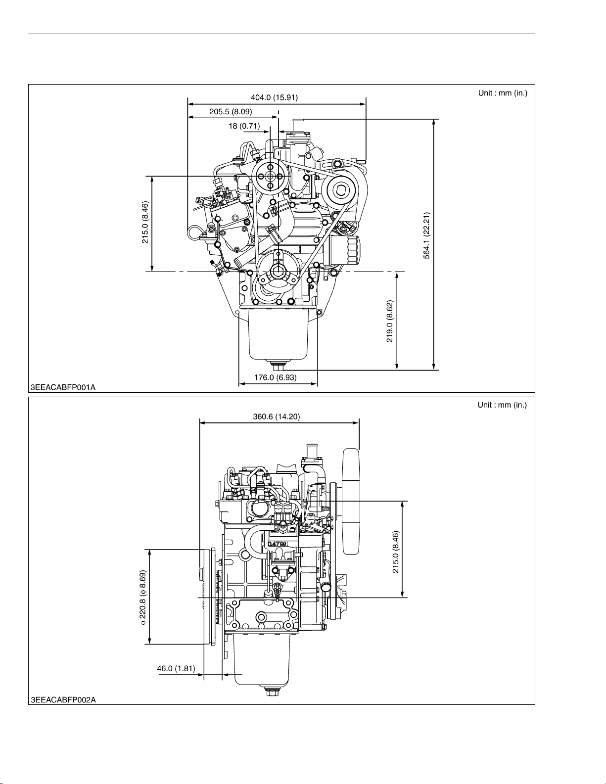
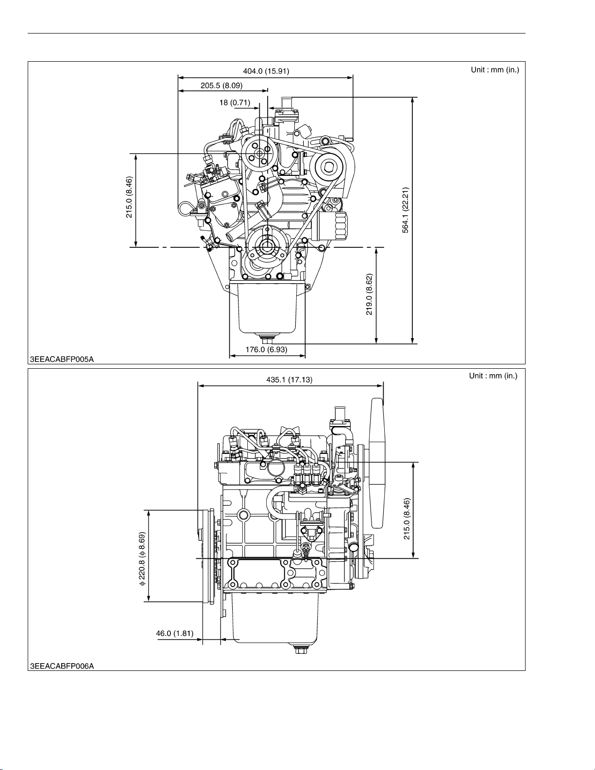
Q Z482-E3B
DIMENSIONS
12
SM-E3B SERIES WSM
KiSC issued 03, 2011 A
Q Z602-E3B
DIMENSIONS
13
SM-E3B SERIES WSM
KiSC issued 03, 2011 A
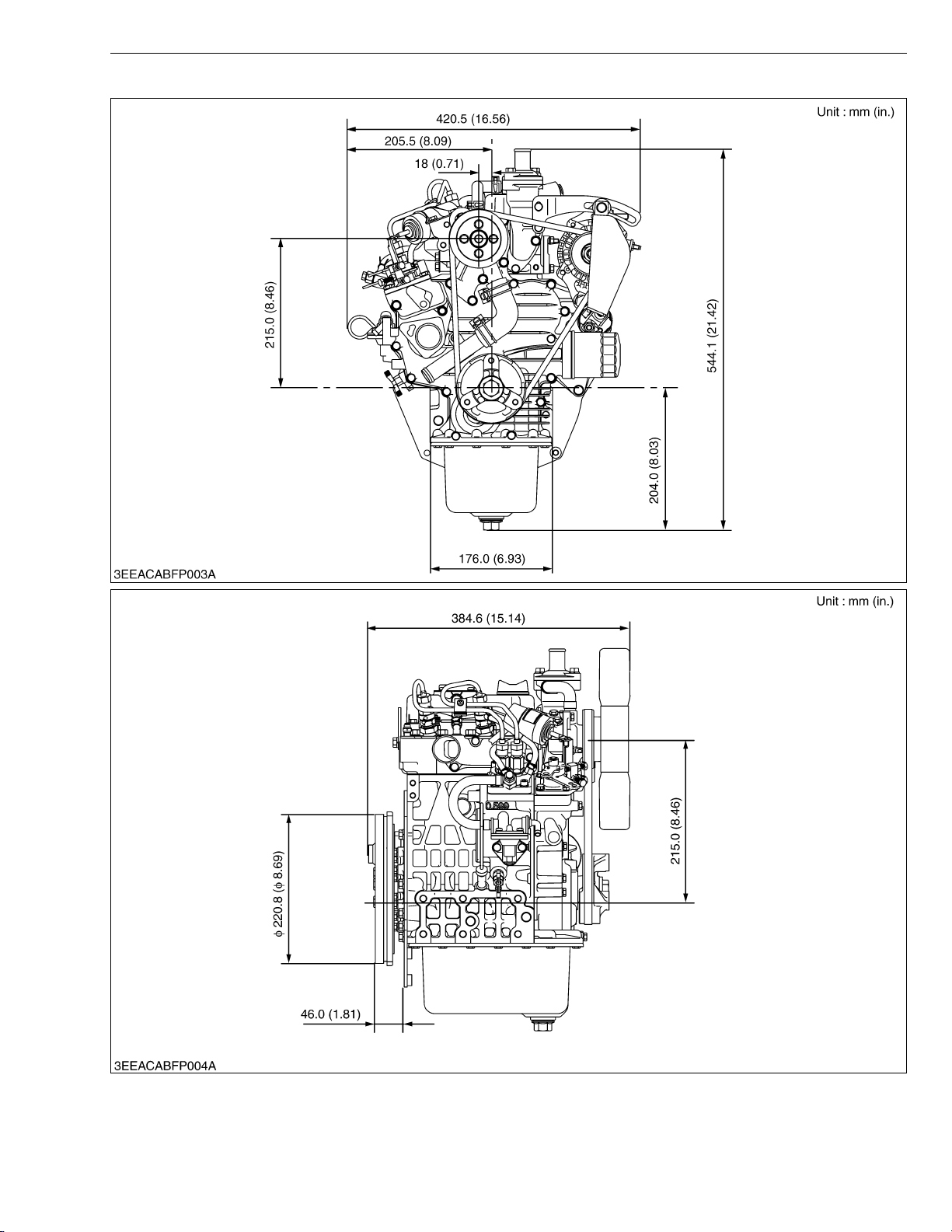
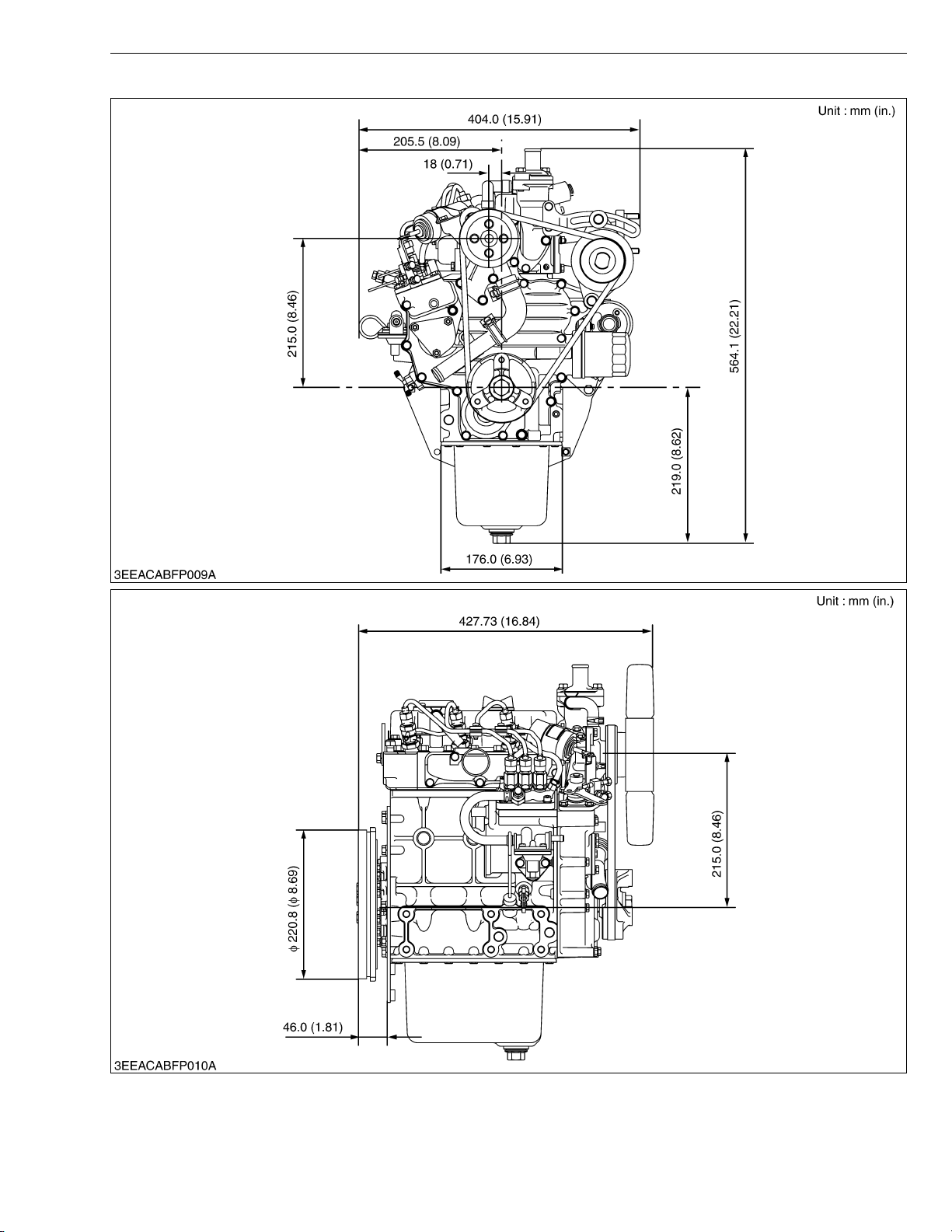
Q D722-E3B
DIMENSIONS
14
SM-E3B SERIES WSM
KiSC issued 03, 2011 A
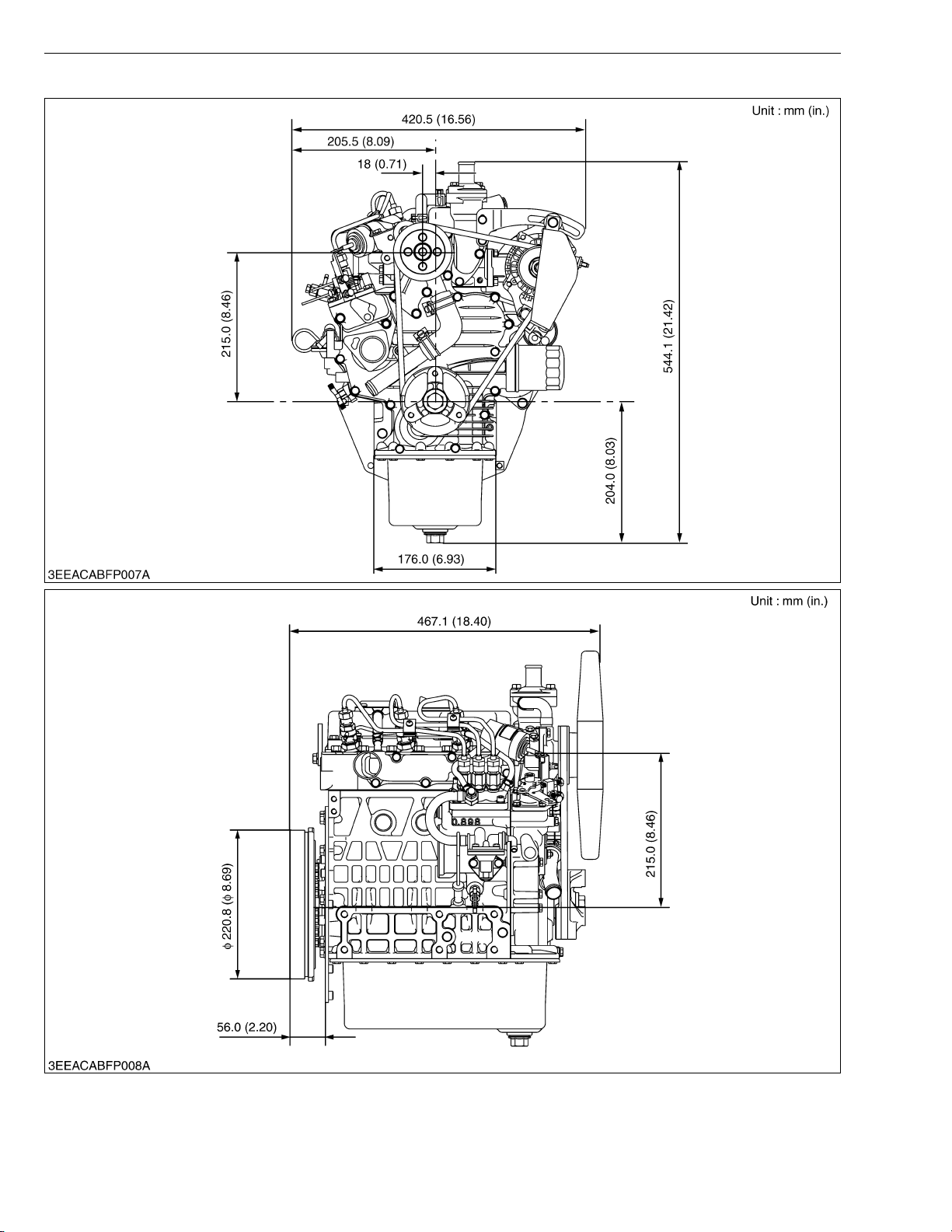
Q D782-E3B
DIMENSIONS
15
SM-E3B SERIES WSM
KiSC issued 03, 2011 A
Q D902-E3B
DIMENSIONS
16

GENERAL
KiSC issued 03, 2011 A
CONTENTS
1. ENGINE IDENTIFICATION ............................................................................. G-1
[1] MODEL NAME AND ENGINE SERIAL NUMBER ................................ G-1
[2] E3B ENGINE............................................................................................. G-2
[3] CYLINDER NUMBER ............................................................................... G-2
2. GENERAL PRECAUTIONS ............................................................................ G-3
3. MAINTENANCE CHECK LIST ....................................................................... G-4
4. CHECK AND MAINTENANCE ....................................................................... G-7
[1] DAILY CHECK POINTS........................................................................... G-7
[2] CHECK POINTS OF INITIAL 50 HOURS ............................................. G-9
[3] CHECK POINT OF EVERY 50 HOURS ............................................. G-11
[4] CHECK POINT OF EVERY 75 HOURS ............................................. G-12
[5] CHECK POINTS OF EVERY 100 HOURS......................................... G-13
[6] CHECK POINT OF EVERY 150 HOURS ........................................... G-16
[7] CHECK POINTS OF EVERY 200 HOURS......................................... G-16
[8] CHECK POINTS OF EVERY 400 HOURS......................................... G-17
[9] CHECK POINTS OF EVERY 500 HOURS......................................... G-18
[10]CHECK POINTS OF EVERY 1 OR 2 MONTHS ............................... G-20
[11]CHECK POINT OF EVERY YEAR....................................................... G-22
[12]CHECK POINT OF EVERY 800 HOURS ........................................... G-23
[13]CHECK POINTS OF EVERY 1500 HOURS ....................................... G-24
[14]CHECK POINTS OF EVERY 3000 HOURS ....................................... G-26
[15]CHECK POINTS OF EVERY 2 YEARS.............................................. G-29
5. SPECIAL TOOLS.......................................................................................... G-33
SM-E3B SERIES WSM
KiSC issued 03, 2011 A
1. ENGINE IDENTIFICATION
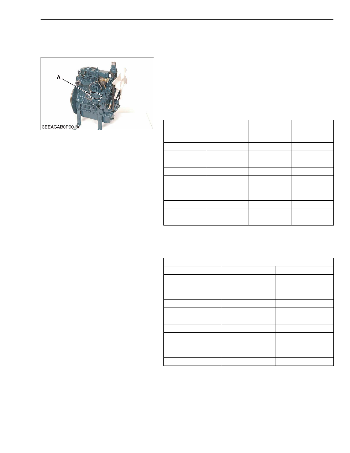
[1] MODEL NAME AND ENGINE SERIAL NUMBER
When contacting the manufacture, always specify your engine
model name and serial number.
The engine model and its serial number need to be identified
before the engine can be serviced or parts replaced.
Q Engine Serial Number
The engine serial number is an identified number for the engine.
It is marked after the engine model number.
It indicates month and year of manufacture as follows.
• Year of manufacture
Alphabet or
Number
6 2006 H 2017
7 2007 J 2018
8 2008 K 2019
9 2009 L 2020
A 2010 M 2021
B 2011 N 2022
C 2012 P 2023
D 2013 R 2024
E 2014 S 2025
F 2015 T 2026
G 2016 V 2027
Year
Alphabet or
Number
G GENERAL
Yea r
A : Engine Model Name and Serial
Number
• Month of manufacture
Month Engine Lot Number
January A0001 ~ A9999 B0001 ~ BZ999
February C0001 ~ C9999 D0001 ~ DZ999
March E0001 ~ E9999 F0001 ~ FZ999
April G0001 ~ G9999 H0001 ~ HZ999
May J0001 ~ J9999 K0001 ~ KZ999
June L0001 ~ L9999 M0001 ~ MZ999
July N0001 ~ N9999 P0001 ~ PZ999
August Q0001 ~ Q9999 R0001 ~ RZ999
September S0001 ~ S9999 T0001 ~ TZ999
October U0001 ~ U9999 V0001 ~ VZ999
November W0001 ~ W9999 X0001 ~ XZ999
December Y0001 ~ Y9999 Z0001 ~ ZZ999
* Alphabetical letters “I” and “O” are not used.
e.g. D902
- 7 B A001
(a) (b)(c) (d)
(a) Engine Model Name : D902
(b) Year : 7 indicates 2007
(c) Month : A or B indicates January
(d) Lot number : (0001 ~ 9999 or A001 ~ Z999)
W1010477
W1011076
G-1
SM-E3B SERIES WSM
KiSC issued 03, 2011 A
G GENERAL
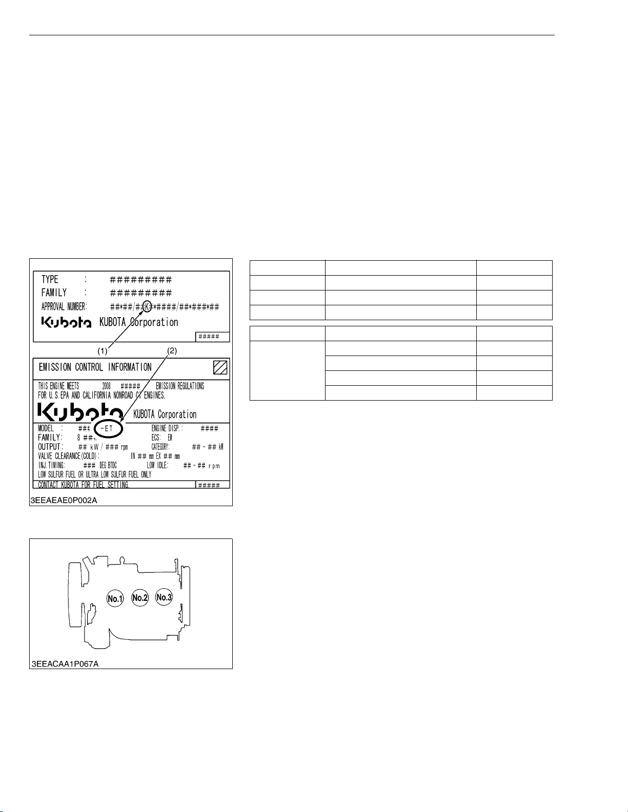
[2] E3B ENGINE
[Example : Engine Model Name D902-E3B-XXXX]
The emission controls previously implemented in various countries to prevent air pollution will be stepped up as
Non-Road Emission Standards continue to change. The timing or applicable date of the specific Non-Road Emission
regulations depends on the engine output classification.
Over the past several years, Kubota has been supplying diesel engines that comply with regulations in the
respective countries affected by Non-Road Emission regulations. For Kubota Engines, E3B will be the designation
that identifies engine models affected by the next emission phase (See the table below).
When servicing or repairing ###-E3B series engines, use only replacement parts for that specific E3B engine,
designated by the appropriate E3B Kubota Parts List and perform all maintenance services listed in the appropriate
Kubota Operator's Manual or in the appropriate E3B Kubota Workshop Manual. Use of incorrect replacement parts
or replacement parts from other emission level engines (for example: E2B engines), may result in emission levels out
of compliance with the original E3B design and EPA or other applicable regulations.Please refer to the emission label
located on the engine head cover to identify Output classification and Emission Control Information. E3B engines are
identified with "ET" at the end of the Model designation, on the US EPA label. Please note : E3B is not marked on the
engine.
Category (1) Engine output classification EU regulation
K From 19 to less than 37 kW STAGE ΙΙΙA
J From 37 to less than 75 kW STAGE ΙΙΙA
I From 75 to less than 130 kW STAGE ΙΙΙA
[3] CYLINDER NUMBER
Category (2) Engine output classification EPA regulation
Less than 19kW Tier 4
ET
(1) EU regulation engine output classification category
(2) “E3B” engines are identified with “ET” at the end of the Model designation, on
the US EPA label.
“E3B” designates Tier 3 and some Interim Tier 4 / Tier 4 models, depending on
engine output classification.
From 19 to less than 56 kW Interim Tier 4
From 56 to less than 75 kW Tier 3
From 75 to less than 130 kW Tier 3
W1031971
The cylinder numbers of KUBOTA diesel engine are designated
as shown in the figure.
The sequence of cylinder numbers is given as No.1, No.2 and
No.3 starting from the gear case side.
W1011077
G-2
SM-E3B SERIES WSM
KiSC issued 03, 2011 A
2. GENERAL PRECAUTIONS
• During disassembly, carefully arrange removed parts in a clean
area to prevent confusion later. Screws, bolts and nuts should be
replaced in their original position to prevent reassembly errors.
• When special tools are required, use KUBOTA genuine special
tools. Special tools which are not frequently used should be
made according to the drawings provided.
• Before disassembling or servicing live wires, make sure to
always disconnect the grounding cable from the battery first.
• Remove oil and dirt from parts before measuring.
• Use only KUBOTA genuine parts for parts replacement to
maintain engine performance and to ensure safety.
• Gaskets and O-rings must be replaced during reassembly.
Apply grease to new O-rings or oil seals before assembling.
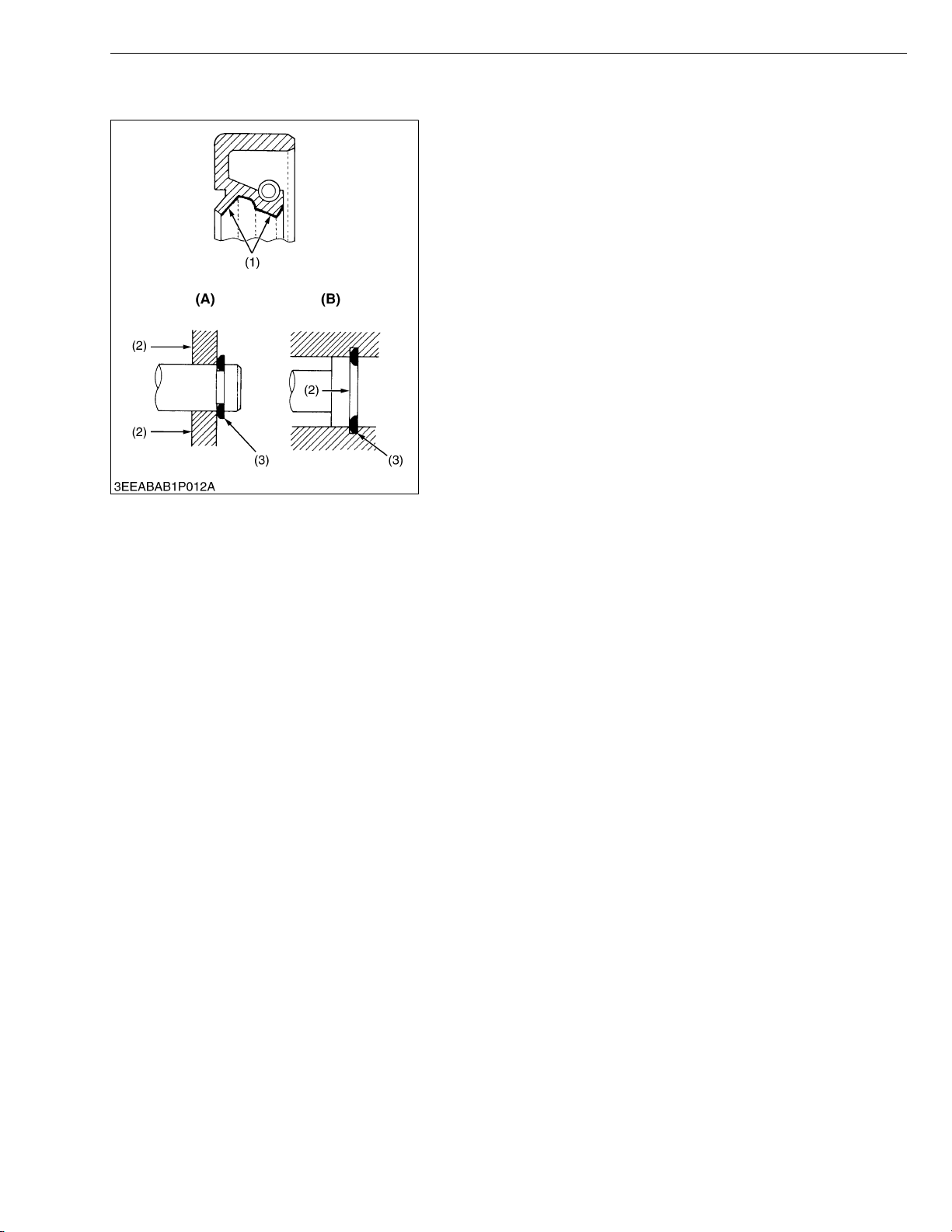
• When reassembling external or internal snap rings, position them
so that the sharp edge faces against the direction from which
force is applied.
• Be sure to perform run-in the serviced or reassembled engine.
Do not attempt to give heavy load at once, or serious damage
may result to the engine.
(1) Grease
(2) Force
(3) Place the Sharp Edge against the
Direction of Force
G GENERAL
(A) External Snap Ring
(B) Internal Snap Ring
W1011734
G-3

SM-E3B SERIES WSM
KiSC issued 03, 2011 A
G GENERAL
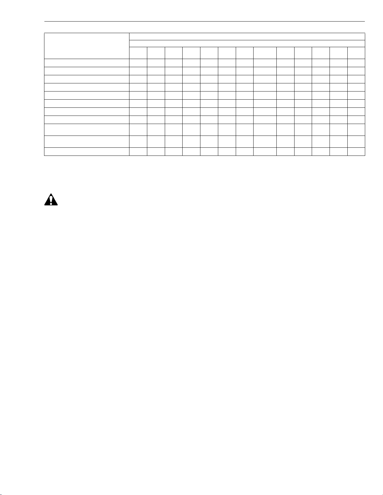
3. MAINTENANCE CHECK LIST
To maintain long-lasting and safe engine performance, make it a rule to carry out regular inspections by following
the table below.
Service Interval
Item
*Checking fuel hoses and clamp
bands
(1) Oil pan depth
(101 mm, 3.98 in.)
Changing
Engine oil
Checking fan belt tension and
damage
*Cleaning air cleaner element
(Replace the element after 6 times
cleaning)
Cleaning fuel filter (element type)
Checking battery electrolyte level
Replacing oil
filter cartridge
Checking radiator hoses and clamp
bands
*Checking intake air line ,
*Replacing fuel filter ,
Cleaning water jacket and radiator
interior
Replacing fan belt ,
(2) Oil pan depth
(121 mm, 4.76 in.)
(3) Extended oil
pan depth
(101 mm, 3.98 in.)
(1) Oil pan depth
(101 mm, 3.98 in.)
(2) Oil pan depth
(121 mm, 4.76 in.)
(3) Extended oil
pan depth
(101 mm, 3.98 in.)
50
hrs75hrs
,
+
,
+
+
+
+
+
100
hrs
,
,
,
,
,
,
150
hrs
,
200
hrs
,
,
,
(1) This oil pan depth is optional for Z482-E3B and D722-E3B.
(2) This oil pan depth is standard for Z482-E3B, D722-E3B and D782-E3B.
(3) This oil pan depth is standard for Z602-E3B and D902-E3B.
+ Change engine oil and replace oil filter cartridge after the first 50 hours of operation.
* The items listed above (* marked) are registered as emission related critical parts by KUBOTA in the U.S. EPA
nonroad emission regulation. As the engine owner, you are responsible for the performance of the required
maintenance on the engine according to the above instruction.
400
hrs
Every
500
hrs
,
1 or 2
months1 year
800
hrs
1500
hrs
3000
hrs2 years
W1029462
G-4
SM-E3B SERIES WSM
CAUTION
KiSC issued 03, 2011 A
Service Interval
Item
Recharging battery ,
*Replacing air cleaner element ,
Checking valve clearance ,
*Checking injection nozzle condition ,
*Checking injection timing ,
*Checking injection pump ,
*Replacing intake air line ,
Replacing battery ,
Replacing radiator hoses and clamp
bands
*Replacing fuel hoses and clamp
bands
Changing radiator coolant (L.L.C.) ,
50
hrs75hrs
100
hrs
150
hrs
200
hrs
400
hrs
Every
500
hrs
1 or 2
months1 year
800
hrs
G GENERAL
1500
3000
hrs
hrs2 years
,
,
* The items listed above (* marked) are registered as emission related critical parts by KUBOTA in the U.S. EPA
nonroad emission regulation. As the engine owner, you are responsible for the performance of the required
maintenance on the engine according to the above instruction.
W1014630
• When changing or inspecting, be sure to level and stop the engine.
G-5

SM-E3B SERIES WSM
KiSC issued 03, 2011 A
G GENERAL
Q NOTE
Engine Oil :
• Refer to the following table for the suitable American Petroleum Institute (API) classification of engine oil
according to the engine type (with internal EGR, external EGR or non-EGR) and the Fuel Type Used :
(Low Sulfur, Ultra Low Sulfur or High Sulfur Fuels).
Engine oil classification (API classification)
Fuel Type
High Sulfur Fuel
[0.05 % (500 ppm) ≤
Sulfur Content <
0.50 % (5000 ppm)]
Engines with non-EGR
Engines with internal EGR
CF
(If the "CF-4, CG-4, CH-4, or CI-4" engine
oil is used with a high-sulfur fuel, change
the engine oil at shorter intervals.
(approximately half))
Engines with external EGR
–
Low Sulfur Fuel
[Sulfur Content <
0.05 % (500 ppm)] or
Ultra Low Sulfur Fuel
[Sulfur Content <
CF, CF-4, CG-4, CH-4 or CI-4
CF or CI-4
(Class CF-4, CG-4 and CH-4 engine oils
cannot be used on EGR type engines.)
0.0015 % (15 ppm)]
EGR : Exhaust Gas Re-circulation
W1024941
• CJ-4 classification oil is intended for use in engines equipped with DPF (Diesel Particulate Filter) and is
Not Recommended for use in Kubota E3 specification engines.
• Oil used in the engine should have API classification and Proper SAE Engine Oil Viscosity according to
the ambient temperatures where the engine is operated.
• With strict emission control regulations now in effect, the CF-4 and CG-4 engine oils have been developed
for use with low sulfur fuels, for On-Highway vehicle engines. When a Non-Road engine runs on high
sulfur fuel, it is advisable to use a "CF or better" classification engine oil with a high Total Base Number
(a minimum TBN of 10 is recommended).
Fuel :
• Cetane Rating : The minimum recommended Fuel Cetane Rating is 45. A cetane rating greater than 50 is
preferred, especially for ambient temperatures below −20 °C (−4 °F) or elevations above 1500 m (5000 ft).
• Diesel Fuel Specification Type and Sulfur Content % (ppm) used, must be compliant with all applicable
emission regulations for the area in which the engine is operated.
• Use of diesel fuel with sulfur content less than 0.10 % (1000 ppm) is strongly recommended.
• If high-sulfur fuel (sulfur content 0.50 % (5000 ppm) to 1.0 % (10000 ppm)) is used as a diesel fuel, change
the engine oil and oil filter at shorter intervals. (approximately half)
• DO NOT USE Fuels that have sulfur content greater than 1.0 % (10000 ppm).
• Diesel fuels specified to EN 590 or ASTM D975 are recommended.
• No.2-D is a distillate fuel of lower volatility for engines in industrial and heavy mobile service. (SAE J313
JUN87)
• Since KUBOTA diesel engines of less than 56 kW (75 hp) utilize EPA Tier 4 and Interim Tier 4 standards,
the use of low sulfur fuel or ultra low sulfur fuel is mandatory for these engines, when operated in US EPA
regulated areas. Therefore, please use No.2-D S500 or S15 diesel fuel as an alternative to No.2-D, and use
No.1-D S500 or S15 diesel fuel as an alternative to No.1-D for ambient temperatures below −10 °C (14 °F).
1) SAE : Society of Automotive Engineers
2) EN : European Norm
3) ASTM : American Society of Testing and Materials
4) US EPA : United States Environmental Protection Agency
5) No.1-D or No.2-D, S500 : Low Sulfur Diesel (LSD) less than 500 ppm or 0.05 wt.%
No.1-D or No.2-D, S15 : Ultra Low Sulfur Diesel (ULSD) 15 ppm or 0.0015 wt.%
G-6
SM-E3B SERIES WSM
IMPORTANTQ
NOTEQ
KiSC issued 03, 2011 A
4. CHECK AND MAINTENANCE
[1] DAILY CHECK POINTS
Checking Engine Oil Level
1. Level the engine.
2. To check the oil level, draw out the dipstick (1), wipe it clean,
reinsert it, and draw it out again.
Check to see that the oil level lies between the two notches.
3. If the level is too low, add new oil to the specified level.
• When using an oil of different maker or viscosity from the
previous, drain old oil. Never mix two different types of oil.
• Be sure to inspect the engine, locating it on a horizontal
place. If placed on gradients, accurately, oil quantity may
not be measured.
• Be sure to keep the oil level between upper and lower limits
of the dipstick. Too much oil may cause a drop in output or
excessive blow-by gas. On the closed breather type engine
in which mist is sucked through port, too much oil may
caused oil hammer. While too little oil, may seize the
engine’s rotating and sliding parts.
(1) Dipstick
G GENERAL
W1016222
G-7
SM-E3B SERIES WSM
CAUTION
IMPORTANTQ
KiSC issued 03, 2011 A
G GENERAL
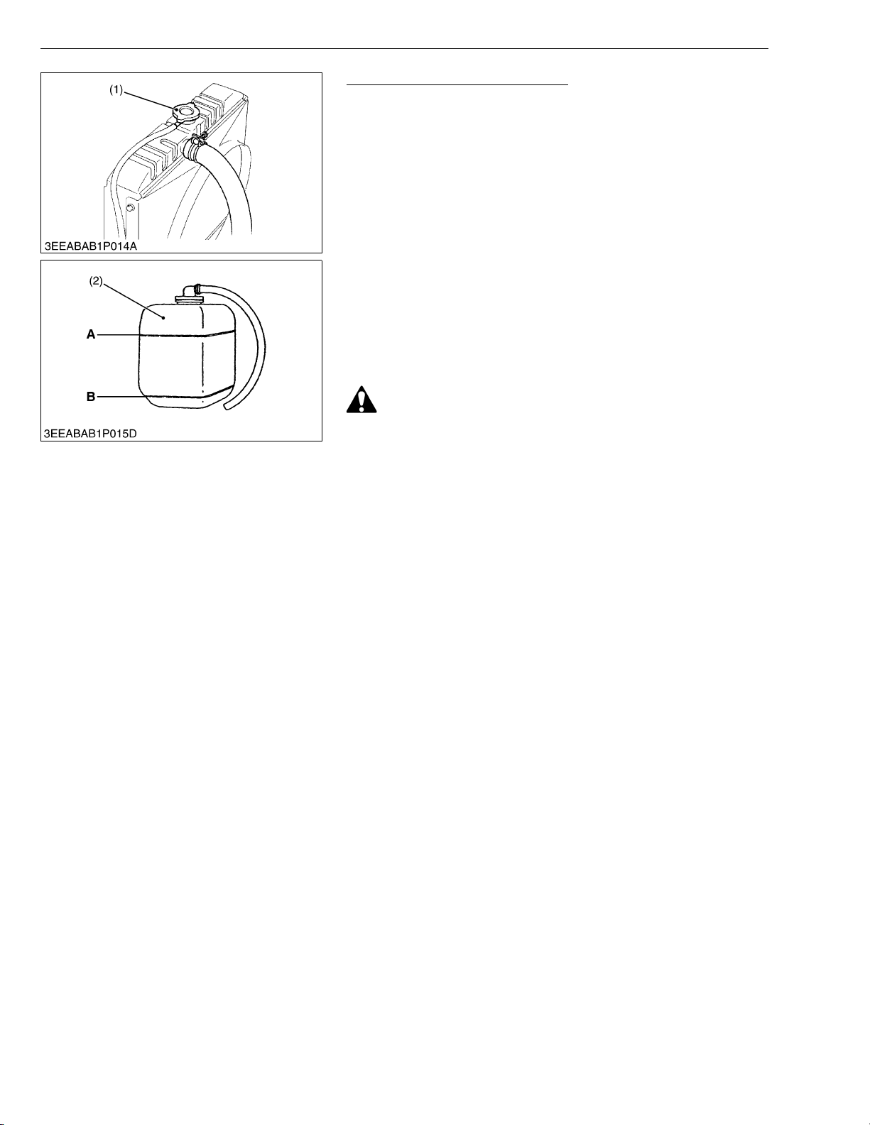
Checking and Replenish Coolant
1. Without recovery tank :
Remove the radiator cap (1) and check to see that the coolant
level is just below the port.
With recovery tank (2) :
Check to see that the coolant level lies between FULL (A) and
LOW (B).
2. If coolant level is too low, check the reason for decreasing
coolant.
(Case 1)
If coolant is decreasing by evaporation, replenish only fresh, soft
water.
(Case 2)
If coolant is decreasing by leak, replenish coolant of the same
manufacture and type in the specified mixture ratio (fresh, soft
water and L.L.C.). If the coolant brand cannot be identified, drain
out all of the remaining coolant and refill with a totally new brand
of coolant mix.
• Do not remove the radiator cap until coolant temperature is
below its boiling point. Then loosen the cap slightly to
relieve any excess pressure before removing the cap
completely.
• During filling the coolant, air must be vented from the engine
coolant passages. The air vents by jiggling the radiator
upper and lower hoses.
• Be sure to close the radiator cap securely. If the cap is loose
or improperly closed, coolant may leak out and the engine
could overheat.
• Do not use an antifreeze and scale inhibitor at the same time.
• Never mix the different type or brand of L.L.C..
(1) Radiator Cap
(2) Recovery Tank
A: FULL
B: LOW
W1035779
G-8
SM-E3B SERIES WSM
CAUTION
IMPORTANTQ
KiSC issued 03, 2011 A
[2] CHECK POINTS OF INITIAL 50 HOURS
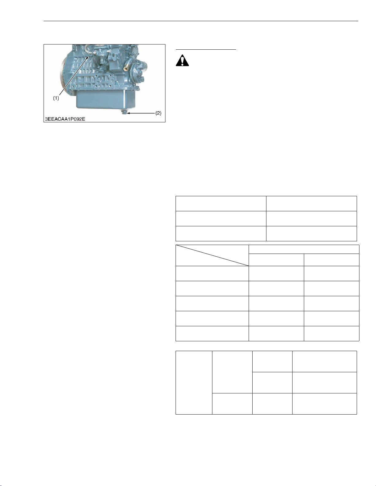
Changing Engine Oil
• Be sure to stop engine before changing engine oil.
1. Start and warm up the engine for approx. 5 minutes.
2. Place an oil pan underneath the engine.
3. To drain the used oil, remove the drain plug (2) at the bottom of
the engine and drain the oil completely.
4. Screw the drain plug (2).
5. Fill new oil up to upper line on the dipstick (1).
• When using an oil of different maker or viscosity from the
previous one, remove all of the old oil.
• Never mix two different types of oil.
• Engine oil should have properties of API classification CF
(See page G-6).
• Use the proper SAE Engine Oil according to ambient
temperature.
• Upon an oil change, be sure to replace the gasket with new
one.
Above 25 °C (77 °F)
0 °C to 25 °C (32 °F to 77 °F)
Below 0 °C (32 °F)
G GENERAL
SAE 30 or SAE 10W-30
SAE 10W-40
SAE 20 or SAE 10W-30
SAE 10W-40
SAE 10W or SAE 10W-30
SAE 10W-40
Oil pan depth
Models
*Z482-E3B
*D722-E3B
D782-E3B –
Z602-E3B
D902-E3B
* 101 mm (3.98 in.) oil pan depth is optional.
Drain plug with
Tightening
torque
(1) Dipstick (2) Drain Plug
copper gasket
Drain plug with
rubber coated
gasket
101 mm (3.98 in.) 121 mm (4.76 in.)
0.55 U.S.gals
0.85 U.S.gals
0.66 U.S.gals
0.98 U.S.gals
M12 × 1.25
M22 × 1.5
M22 × 1.5
Engine oil capacity
2.1 L
3.2 L
2.5 L
3.7 L
2.5 L
0.66 U.S.gals
3.8 L
1.0 U.S.gals
3.6 L
0.95 U.S.gals
–
–
33 to 37 N·m
3.3 to 3.8 kgf·m
24 to 27 lbf·ft
64 to 73 N·m
6.5 to 7.5 kgf·m
47 to 54 lbf·ft
45 to 53 N·m
4.5 to 5.5 kgf·m
33 to 39 lbf·ft
W1016604
G-9
SM-E3B SERIES WSM
CAUTION
IMPORTANTQ
NOTEQ
KiSC issued 03, 2011 A
G GENERAL
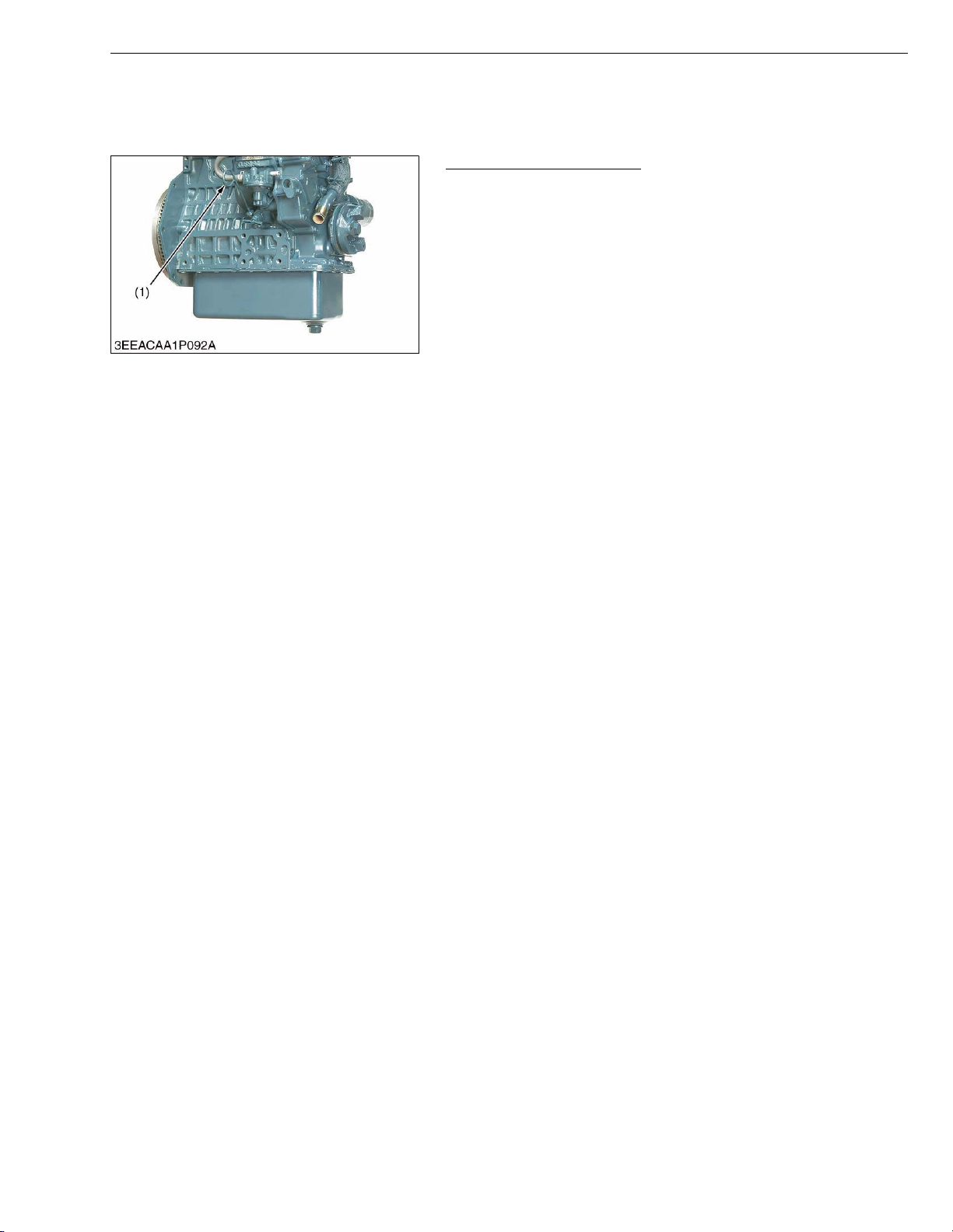
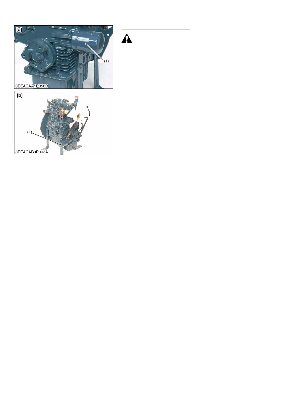
Replacing Oil Filter Cartridge
• Be sure to stop the engine before changing filter cartridge.
1. Remove the oil filter cartridge (1) with the filter wrench.
2. Apply a slight coat of oil onto the new cartridge gasket.
3. To install the new cartridge, screw it in by hand. Over tightening
may cause deformation of rubber gasket.
4. After the new cartridge has been replaced, the engine oil
normally decrease a little. Thus see that the engine oil does not
leak through the seal and be sure to read the oil level on the
dipstick. Then, replenish the engine oil up to the specified level.
• To prevent serious damage to the engine, replacement
element must be highly efficient. Use only a KUBOTA
genuine filter or its equivalent.
• The oil pan of 101 mm (3.98 in.) depth is optional for Z482E3B and D722-E3B. This service interval is every 150 hours.
(1) Engine Oil Filter Cartridge [a] Standard Type
[b] One-side Maintenance Type
W1017137
G-10
SM-E3B SERIES WSM
CAUTION
NOTEQ
KiSC issued 03, 2011 A
[3] CHECK POINT OF EVERY 50 HOURS
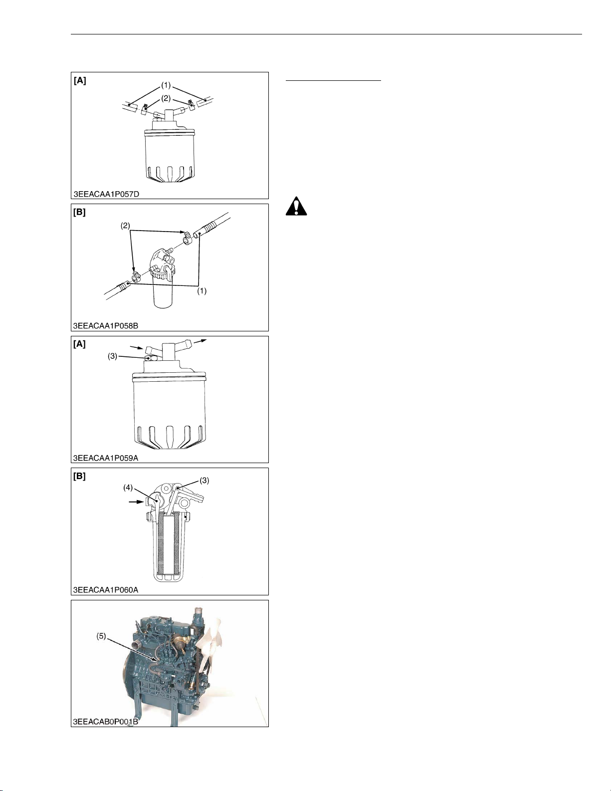
Checking Fuel Hose
1. If the clamp (2) is loose, apply oil to the threads and securely
retighten it.
2. The fuel hose (1) is made of rubber and ages regardless of the
period service.
Change the fuel hose together with the clamp every two years.
3. However, if the fuel hose and clamp are found to be damaged or
deteriorate earlier than two years, then change or remedy.
4. After the fuel hose and the clamp have been changed, bleed the
fuel system.
• Stop the engine when attempting the check and change
prescribed above.
(When bleeding fuel system)
1. Fill the tank with fuel and open the cock (4). ([B] only.)
2. Loosen the air vent plug (3) of the fuel filter a few turns.
3. Screw back the plug when bubbles do not come up any more.
4. Open the air vent cock (5) on top of the fuel injection pump.
5. If equipped electrical fuel feed pump, turn the key to AC position
and pump the fuel up for 10 to 15 seconds.
If equipped mechanical fuel feed pump, set the stop lever on stop
position and crank the engine for 10 to 15 seconds.
6. Close securely the air vent cock after air bleeding.
G GENERAL
• Always keep the air vent cock on the fuel injection pump
closed except when air is vented, or it may cause the engine
to stop.
(1) Fuel Hose
(2) Clamp
(3) Air Vent Plug
(4) Fuel Cock
(5) Air Vent Cock
[A] Cartridge Type
[B] Element Type
W1035921
G-11
 Loading...