

Page 1
OPERATOR'S MANUAL
UTILITY VEHICLE
PRINTED IN U.S.A.
English (U.S.A.)
Code No. K7211-7121-5
KUBOTA Corporation 2011
©
R
T
V
4
0
0
C
i
1AYAACPAP0010
READ AND SAVE THIS MANUAL
Page 2
ABBREVIATION LIST
Abbreviations Definitions
2WD
4WD
API
ASABE
ASTM
DIN
fpm
Km/h
MPH
m/s
PTO
RH/LH
ROPS
rpm
r/s
SAE
CVT
Two Wheel Drive
Four Wheel Drive
American Petroleum Institute
American Society of Agricultural and Biological Engineers, USA
American Society for Testing and Materials, USA
Deutsches Institut für Normung, GERMANY
Feet Per Minute
Kilometers Per Hour
Miles Per Hour
Meters Per Second
Power Take Off
Right-hand and left-hand sides are determined by facing
in the direction of forward travel
Roll-Over Protective Structures
Revolutions Per Minute
Revolutions Per Second
Society of Automotive Engineers, USA
Continuously Variable Transmission
KUBOTA Corporation is ···
Since its inception in 1890, KUBOTA Corporation has grown to
rank as one of the major firms in Japan.
To achieve this status, the company has through the years
diversified the range of its products and services to a remarkable
extent, until today, 19 plants and 16,000 employees produce over
1,000 different items, large and small.
All these products and all the services which accompany them,
however, are unified by one central commitment. KUBOTA makes
products which, taken on a national scale, are basic necessities.
Products which are indispensable, products intended to help
individuals and nations fulfill the potential inherent in their
environment. For KUBOTA is the Basic Necessities Giant.
This potential includes water supply, food from the soil and from
the sea, industrial development, architecture and construction,
transportation.
California Proposition 65
WARNING
Engine exhaust, some of its constituents,
certain vehicle components and fluids,
contain or emit chemicals known to the
State of California to cause cancer and birth
defects or other reproductive harm.
IMPORTANT
The engine in this machine is equipped by the manufacture with a
standard spark arrester.
It is a violation of California Public Resource Code Section 4442 to
use or operate this engine on or near any forest-covered, brushcovered land, or grass- covered land unless the exhaust system is
equipped with a working spark arrester meeting state laws. Other
states or federal areas may have similar laws.
This spark ignition system complies with Canadian ICES-002.
Thousands of people depend on KUBOTA's know-how, technology,
experience and customer service. You too can depend on
KUBOTA.
Page 3

UNIVERSAL SYMBOLS
As a guide to the operation of your vehicle, various universal symbols have been utilized on the instruments and
controls. The symbols are shown below with an indication of their meaning.
Safety Alert Symbol
Brake
Brake & Parking Brake
Battery Charging Condition
Engine Oil-Pressure
Turn Signal
Engine-Stop
Engine-Run
Engine-Diagnostic
Starter Control
Differential Lock
Master Lighting Switch
Headlight
Audible Warning Device
Four-Wheel Drive-On
Four-Wheel Drive-Off
Lock
Unlock
Page 4

FOREWORD
You are now the proud owner of a KUBOTA Vehicle. This vehicle is a product of
KUBOTA quality engineering and manufacturing. It is made of excellent materials
and under a rigid quality control system. It will give you long, satisfactory service.
To obtain the best use of your vehicle, please read this manual carefully. It will help
you become familiar with the operation of the vehicle and contains many helpful
hints about vehicle maintenance. This manual contains instructions for minor
maintenance, but information about major repairs is outlined in the KUBOTA Work
Shop Manual and should be performed only by a KUBOTA Dealer Technician. It is
KUBOTA's policy to utilize as quickly as possible every advance in our research.
The immediate use of new techniques in the manufacture of products may cause
some small parts of this manual to become outdated. KUBOTA distributors and
dealers will have the most up-to-date information. Please do not hesitate to consult
with them.
3
This symbol, the industry's ''Safety Alert Symbol'', is used throughout this manual
and on labels on the machine itself to warn of the possibility of personal injury.
Read these instructions carefully. It is essential that you read the instructions and
safety regulations before you attempt to assemble or use this unit.
3
3
3
IMPORTANT :
NOTE :
DANGER :
WARNING :
CAUTION :
Indicates an imminently hazardous situation which, if not
avoided, will result in death or serious injury.
Indicates a potentially hazardous situation which, if not
avoided, could result in death or serious injury.
Indicates a potentially hazardous situation which, if not
avoided, could result in minor or moderate injury.
Indicates that equipment or property damage could result if
instructions are not followed.
Gives helpful information.
SAFETY FIRST
Page 5

CONTENTS
SAFE OPERATION ............................................................................................ -1
SERVICING OF VEHICLE........................................................................................... 1
SPECIFICATIONS....................................................................................................... 2
SPECIFICATION TABLE ......................................................................................... 2
TRAVELING SPEEDS ............................................................................................. 3
VEHICLE LIMITATIONS.............................................................................................. 4
INSTRUMENT PANEL AND CONTROLS................................................................... 5
LOCATION OF PARTS............................................................................................ 5
PRE-OPERATION CHECK ......................................................................................... 9
DAILY CHECK ......................................................................................................... 9
OPERATING THE ENGINE....................................................................................... 10
STARTING THE ENGINE ...................................................................................... 10
Cold Weather Starting ....................................................................................................12
STOPPING THE ENGINE...................................................................................... 12
WARMING UP ....................................................................................................... 12
JUMP STARTING .................................................................................................. 13
OPERATING THE VEHICLE ..................................................................................... 14
OPERATING NEW VEHICLE ................................................................................ 14
Do not Operate the Vehicle at Full Speed for the First 50 Hours ...................................14
Changing Lubricating Oil for New Vehicles .................................................................... 14
STARTING ............................................................................................................. 14
Seat Belt .........................................................................................................................14
Head Light Switch........................................................................................................... 15
Horn Button.....................................................................................................................15
Brake Pedal ....................................................................................................................16
Range Gear Shift Lever..................................................................................................16
4WD Lever......................................................................................................................17
Parking Brake Lever ....................................................................................................... 17
Speed Control Pedal.......................................................................................................17
STOPPING............................................................................................................. 18
Stopping.......................................................................................................................... 18
CHECK DURING DRIVING ................................................................................... 18
Immediately Stop the Engine if:......................................................................................18
Easy Checker(TM)..........................................................................................................19
Fuel Gauge.....................................................................................................................19
Hourmeter.......................................................................................................................20
PARKING ............................................................................................................... 20
Parking Brake Lever ....................................................................................................... 20
ACCESSORY......................................................................................................... 21
12V Electric Outlet..........................................................................................................21
OPERATING TECHNIQUES ................................................................................. 21
Differential Lock..............................................................................................................21
Unfamiliar Terrain ...........................................................................................................22
Page 6

CONTENTS
Driving in Reverse ..........................................................................................................22
Driving in "4WD" .............................................................................................................23
Turning the Vehicle.........................................................................................................23
Hills.................................................................................................................................24
Traversing Hillsides ........................................................................................................24
Sliding and Skidding .......................................................................................................24
Driving through Water..................................................................................................... 25
CARGO BED ............................................................................................................. 26
CARGO BED.......................................................................................................... 26
General Caution.............................................................................................................. 26
Max. Cargo Load ............................................................................................................26
Cargo Bed Tailgate......................................................................................................... 27
Raising and Lowering the Cargo Bed.............................................................................28
TIRES AND WHEELS ............................................................................................... 29
TIRES..................................................................................................................... 29
Inflation Pressure............................................................................................................29
Tire Type and Use ..........................................................................................................29
WHEELS ................................................................................................................ 30
SHOCK ABSORBERS ........................................................................................... 30
Rear Shock Absorber Spring Adjustment....................................................................... 30
TOWING AND TRANSPORTING.............................................................................. 31
TOWING AND TRANSPORTING .......................................................................... 31
Rear Trailer Hitch............................................................................................................31
Front Trailer Hitch...........................................................................................................31
Winch Mount Bracket......................................................................................................32
MAINTENANCE......................................................................................................... 33
SERVICE INTERVALS .......................................................................................... 33
LUBRICANTS AND FUEL...................................................................................... 36
PERIODIC SERVICE................................................................................................. 37
HOW TO OPEN THE HOOD AND TILT THE SEAT.............................................. 37
Hood ...............................................................................................................................37
Operator's Seat...............................................................................................................38
HOW TO RAISE THE CARGO BED...................................................................... 38
Raising and Lowering the Cargo Bed.............................................................................38
JACK-UP POINT.................................................................................................... 39
Front End........................................................................................................................39
Rear End......................................................................................................................... 39
DAILY CHECK ....................................................................................................... 40
Walk Around Inspection.................................................................................................. 40
Checking Amount of Fuel and Refueling ........................................................................40
Checking Engine Oil Level..............................................................................................41
Checking Transmission Fluid Level................................................................................42
Checking Brake Fluid Level............................................................................................42
Checking Brake Pedal .................................................................................................... 43
Checking Parking Brake .................................................................................................43
Checking Gauges, Meter and Easy Checker(TM) .......................................................... 43
Checking Head Light, etc................................................................................................ 43
Checking Seat Belt and ROPS.......................................................................................43
Page 7

CONTENTS
Checking Joint Boot........................................................................................................44
Checking Tire Inflation Pressure.....................................................................................44
EVERY 50 HOURS ................................................................................................ 45
Greasing .........................................................................................................................45
Checking Engine Start System.......................................................................................46
EVERY 100 HOURS .............................................................................................. 46
Checking Wheel Bolt Torque..........................................................................................46
Changing Engine Oil....................................................................................................... 47
Cleaning Engine Air Cleaner Element ............................................................................48
Cleaning CVT Air Cleaner Element ................................................................................48
Checking Spark Plug Condition & Gap........................................................................... 49
Checking Fuel Line.........................................................................................................50
Checking Carbon Canister Air Filter ............................................................................... 51
Checking Battery Condition ............................................................................................51
Adjusting Toe-in.............................................................................................................. 53
Cleaning Spark Arrester .................................................................................................54
EVERY 200 HOURS .............................................................................................. 54
Adjusting Parking Brake Lever .......................................................................................54
Replacing Engine Oil Filter .............................................................................................55
Changing Engine Oil in Clutch Case ..............................................................................55
Checking and Cleaning Engine Cooling Air Inlet and Engine Cooling Fin......................56
Checking Brake Pedal .................................................................................................... 57
Checking Brake Light Switch..........................................................................................57
Checking CVT Belt .........................................................................................................57
EVERY 300 HOURS .............................................................................................. 58
Checking Tire..................................................................................................................58
Adjusting Engine Valve Clearance .................................................................................58
EVERY 400 HOURS .............................................................................................. 58
Changing Transmission Oil.............................................................................................58
Changing Front Axle Case Oil ........................................................................................59
EVERY 500 HOURS .............................................................................................. 60
Cleaning Engine Combustion Chamber .........................................................................60
EVERY 1000 HOURS or EVERY 1 YEAR............................................................. 60
Replacing Engine Air Cleaner Element ..........................................................................60
Replacing CVT Air Cleaner Element ..............................................................................60
EVERY 1 YEAR ..................................................................................................... 60
Checking Engine Breather Hose ....................................................................................60
Checking Brake Hose and Pipe...................................................................................... 60
Checking Engine Intake Air Line.....................................................................................61
Checking CVT Intake Air Line.........................................................................................61
EVERY 2 YEARS................................................................................................... 62
Changing Brake Fluid ..................................................................................................... 62
Replacing Fuel Hose ......................................................................................................62
EVERY 4 YEARS................................................................................................... 62
Replacing Engine Breather Hose ...................................................................................62
Replacing Brake Master Cylinder (Inner Parts) ..............................................................62
Replacing Engine Intake Air Line....................................................................................62
Replacing CVT Intake Air Line........................................................................................62
Replacing Brake Hose....................................................................................................62
SERVICE AS REQUIRED...................................................................................... 62
Checking Brake Pad.......................................................................................................62
Adjusting Parking Brake .................................................................................................63
Page 8

CONTENTS
Adjusting Alternator Drive Belt Tension..........................................................................63
Replacing Fuse...............................................................................................................63
Replacing Slow-Blow Fuses ........................................................................................... 64
Replacing Light Bulb.......................................................................................................65
STORAGE ................................................................................................................. 66
VEHICLE STORAGE ............................................................................................. 66
REMOVING THE VEHICLE FROM STORAGE..................................................... 66
TROUBLESHOOTING............................................................................................... 67
ENGINE TROUBLESHOOTING ............................................................................ 67
BATTERY TROUBLESHOOTING ......................................................................... 69
MACHINE TROUBLESHOOTING ......................................................................... 70
OPTIONS................................................................................................................... 71
ENGINE EMISSION RELATED INFORMATION....................................................... 72
INDEX........................................................................................................................ 73
Page 9
SAFE OPERATION
-1SAFE OPERATION
Careful operation is your best insurance against an
accident.
Read and understand this Operator's Manual carefully
before operating the vehicle.
All operators, no matter how much experience they may
have, should read this and other related manuals before
operating the vehicle or any implement attached to it. It is
the owner's obligation to instruct all operators in safe
operation.
1. BEFORE OPERATING THE VEHICLE
1. Know your equipment and its limitations. Read this
entire manual before attempting to start and operate
the vehicle.
2. Pay special attention to the Danger, Warning and
Caution labels on the vehicle.
3. Do not remove Roll-Over Protective Structures
(ROPS) for any application and fasten seat belts at all
times. This combination will reduce the risk of serious
injury or death, should the vehicle be upset.
If the ROPS is loosened or removed for any reason,
make sure that all parts are reinstalled correctly before
operating the vehicle.
Never modify or repair a ROPS because welding,
bending, drilling, grinding, or cutting may weaken the
structure.
A damaged ROPS structure must be replaced, not
repaired or revised.
If any structural member of the ROPS is damaged,
replace the entire structure at your local KUBOTA
Dealer.
5. Do not operate the vehicle or any implement attached
to it while under the influence of alcohol, medication,
controlled substances or while fatigued.
6. Carefully check the vicinity before operating the
vehicle or any implement attached to it. Check for
overhead clearance which may interfere with the CAB
or ROPS. Do not allow any bystanders around or near
the vehicle during operation.
7. Never allow anyone without a valid driver's license to
operate this vehicle.
8. Before allowing other people to use your vehicle,
explain how to operate and have them read this
manual before operation.
9. Never wear loose, torn, or bulky clothing around the
vehicle. It may catch on moving parts or controls,
leading to the risk of an accident. Use additional safety
items, e.g. helmet, safety boots or shoes, eye and
hearing protection, gloves, etc., as appropriate or
required.
10.This vehicle is for off road use only.
KUBOTA does not recommend operating on public
roads.
11.In addition to the driver, only 1 passenger should ride
in the vehicle.
Minimum age for passenger is 5 years old.
12.Keep all shields in place and stay away from all
moving parts.
13.Check brakes, speed control pedal, and other
mechanical parts for improper adjustment and wear.
Replace worn or damaged parts promptly. Check the
tightness of all nuts and bolts regularly. (For further
details, see "MAINTENANCE" section.)
14.Keep your vehicle clean. Dirt, grease, and trash build
up may contribute to fires and lead to personal injury.
15.Use only implements meeting the specifications listed
under "VEHICLE LIMITATIONS" in this manual or
implements approved by KUBOTA.
16.The maximum cargo capacity of this vehicle is 200kg.
Reduce cargo capacity to match operating conditions.
Do not carry anything which raises the center-ofgravity and sticks outside the cargo bed.
17.Do not modify the vehicle. Unauthorized modification
may affect the function of the vehicle, which may result
in personal injury.
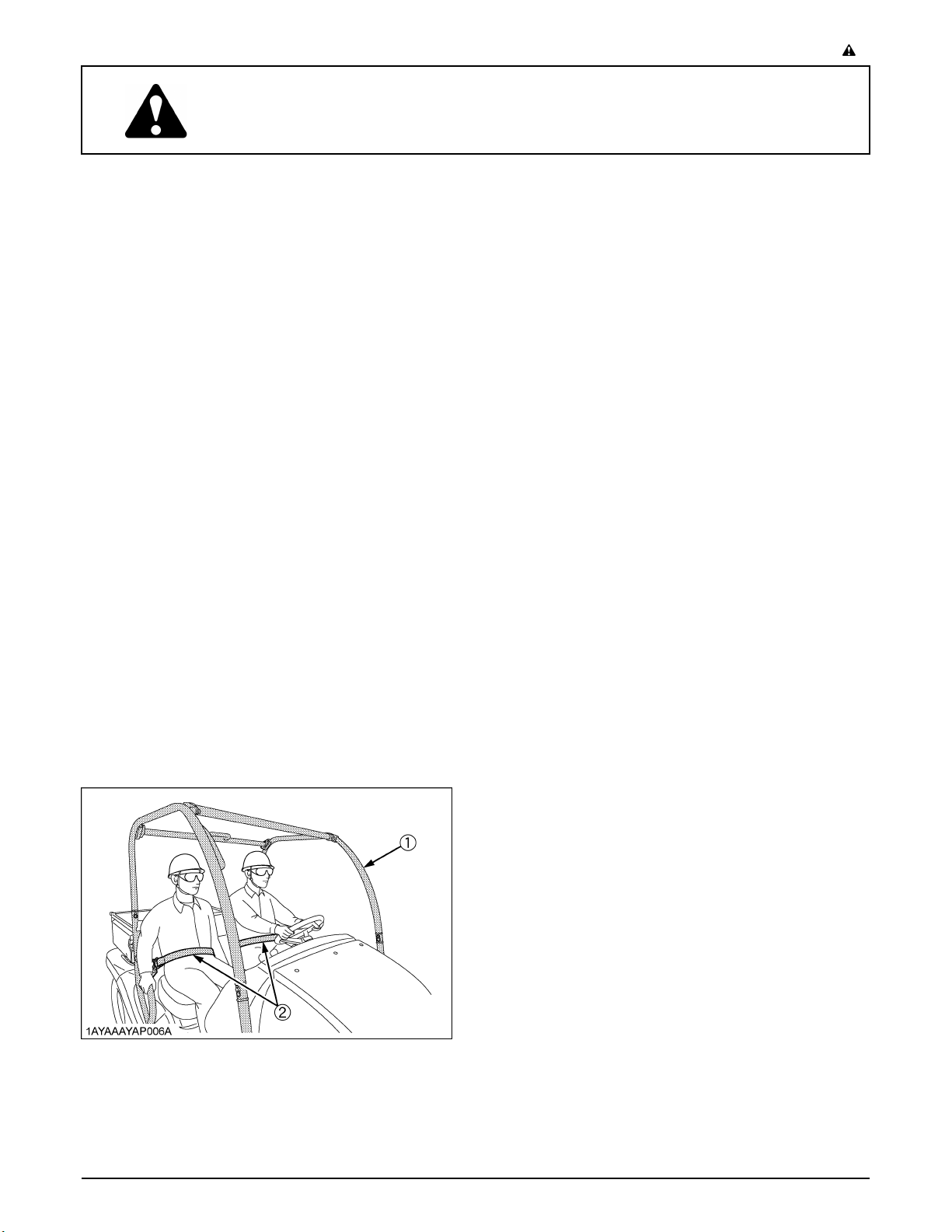
(1) ROPS
(2) Seat belt
4. Always use the seat belts. Check the seat belts
regularly and replace if frayed or damaged.
Page 10
SAFE OPERATION-2
2. OPERATING THE VEHICLE
Operator safety is a priority. Safe operation, specifically
with respect to overturning hazards, entails understanding
the equipment and environmental conditions at the time of
use. Some prohibited uses which can affect overturning
hazards include traveling and turning with implements
and loads carried too high etc. This manual sets forth
some of the obvious risks, but the list is not, and cannot
be, exhaustive. It is the operator's responsibility to be alert
for any equipment or environmental condition that could
compromise safe operation.
5. The vehicle cannot turn with the differential locked and
attempting to do so could be dangerous.
6. Do not operate near ditches, holes, embankments, or
other ground surface features which may collapse
under the vehicle's weight. The risk of vehicle upset is
even higher when the ground is loose or wet.
7. Watch where you are going at all times. Watch for and
avoid obstacles. Be alert at row ends, near trees, and
other obstructions.
8. When working in groups, always let the others know
what you are going to do before you do it.
9. Never try to get on or off a moving vehicle.
10.Do not stand between vehicle and trailer unless
parking brake is applied.
C Starting
1. Always sit in the operator's seat when starting engine
or operating levers or controls.
2. Before starting the engine, make sure that all levers
are in their neutral positions, that the parking brake is
engaged.
3. Do not start engine by shorting across starter
terminals or bypassing the safety start switch. The
vehicle may start in gear and move if normal starting
circuitry is bypassed.
4. Be sure that the operator (and passenger) seat belts
are fastened.
5. Do not operate or idle engine in a non-ventilated area.
Carbon monoxide gas is colorless, odorless, and
deadly.
C Operating
1. Do not wear headphones while operating.
2. Pull only from the trailer hitch (if equipped). Never hitch
to axle housing or any other point except trailer hitch;
such arrangements will increase the risk of serious
personal injury or death due to a vehicle upset.
C Safety for children
Tragedy can occur if the operator is not alert to the
presence of children. Children generally are attracted to
vehicles and the work they do.
1. Never assume that children will remain where you last
saw them.
2. Keep children out of the work area and under the
watchful eye of another responsible adult.
3. Be alert and shut your vehicle down if children enter
the work area.
4. Never carry children in the cargo bed. There is no safe
place for them to ride. No person under the age of 5
may ride as a passenger in this vehicle. A passenger
under 5 years of age requires special restraints which
are not available with this vehicle.
5. Never allow children to operate the vehicle even under
adult supervision.
6. Never allow children to play on the vehicle or on the
implement.
7. Use extra caution when backing up. Look behind and
down to make sure area is clear before moving.
8. Whenever possible, park your vehicle on a firm, flat
and level surface. If this is not possible, park it across
the slope. Set the parking brake(s), lower the
implements to the ground, remove the key from the
ignition and chock the wheels.
(1) Trailer hitch (if equipped)
3. Keep all shields and guards in place. Replace any that
are missing or damaged.
4. Avoid sudden starts. To avoid upsets, slow down
when turning, on uneven ground, and before stopping.
C Operating on slopes
Slopes are a major factor related to loss-of-control and tipover accidents, which can result in severe injury or death.
All slopes require extra caution.
1. Travel straight up or down hill.
2. Reduce load when operating on hilly or over rough
terrain.
3. Keep front wheels straight at crest of hill or going over
bumps.
4. Do not stop or start suddenly when going uphill or
downhill. Be especially cautious when changing
direction on slopes.
Page 11

-3SAFE OPERATION
5. If vehicle stops or loses power going up a hill, lock
parking brake to hold vehicle on slope. Maintain
direction of travel and release brake slowly. Back
straight downhill while maintaining control. Do not turn
vehicle sideways. Vehicle is more stable in a straight
forward or rearward position.
6. When riding on soft terrain, turn front wheels slightly
uphill to keep vehicle on a straight line across the hill.
7. If the vehicle begins to tip, turn front wheels downhill to
gain control before proceeding.
(1) To avoid upsets, always back up steep slopes. If
you cannot back up the slope or if you feel uneasy
on it, do not operate on it. Stay off slopes too
steep for safe operation.
(2) Driving forward out of a ditch, mired condition or
up a steep slope increases the risk of a vehicle to
be upset backward. Always back out of these
situations. Extra caution is required with 4-wheel
drive mode because the increased traction can
give the operator false confidence in the vehicle's
ability to climb slopes.
(3) Keep all movement on slopes slow and gradual.
Do not make sudden changes in speed, direction
or apply brake and make sudden motions of the
steering wheel.
(4) Special attention should be made to the weight
and location of implements and loads as such will
affect the stability of the vehicle.
C Operation in inclement conditions
1. Only operate during daylight or with good artificial
light.
2. Operate vehicle in an open, unobstructed area.
3. Use helmet and/or protective gear for certain
operating conditions.
4. Reduce speed according to trail, terrain and visibility
conditions.
5. Never drive exceeding the limit of visibility. Slow down
near crest of hill until getting a clear view of the other
side.
6. Stay alert for holes, rocks and other hidden hazards in
the terrain.
7. Never cross any body of water where depth may be
unknown to the operator (Deep water is considered
anything above the bottom edge of the axle cap).
Choose a course within the waterway where both
banks have a gradual incline. Cross at a point known
to be safe.
5. Do not apply the differential lock while traveling at high
speeds. The vehicle may run out of control.
6. Avoid sudden motions of the steering wheel as they
can lead to a dangerous loss of stability. The risk is
especially great when the vehicle is traveling at high
speeds.
C Other miscellaneous
1. Clean platform if dirty and remove any debris from
around foot controls.
2. Always keep both hands on the steering wheel.
3. Always keep arms and legs inside the operating
compartment.
4. Never operate the vehicle while standing.
5. Do not tow a cart with any riders on it.
6. Never attempt wheelies, jumps or other stunts.
3. HAULING LOADS IN THE CARGO BED
1. No riders in cargo bed or anywhere else.
2. Do not overload vehicle. Securely anchor all loads.
3. Be sure load is evenly distributed.
4. Reduce cargo capacity when operating on rough or
hilly terrain.
5. Balance loads evenly and secure them. Braking could
shift the load and affect vehicle stability.
6. Never operate vehicle with the cargo bed raised.
7. Operate cargo bed dump with vehicle stationary and
parking brake locked. Do not dump while moving.
8. Operate the cargo bed dump on level ground only.
9. Do not place hands or body under the cargo bed when
lowering bed.
4. PARKING THE VEHICLE
1. Lower all implements to the ground, place all control
levers in their neutral positions, set the parking brake,
stop the engine, and remove the key.
2. Make sure that the vehicle has come to a complete
stop before dismounting.
3. Avoid parking on steep slopes, if at all possible park on
a firm and level surface; if not, park across a slope with
chock the wheels and always with attachment on the
ground.
Failure to comply with this warning may allow the
vehicle to move and could cause injury or death.
C Driving the vehicle at high speeds
1. Check the front wheel engagement. The braking
characteristics are different between 2 and 4 wheel
drive. Be aware of the difference and use carefully.
2. Always slow the vehicle down before turning. Turning
at high speed may tip the vehicle over.
3. Turn the headlights on.
4. Drive at speeds that allow you to maintain control at all
times.
Page 12
SAFE OPERATION-4
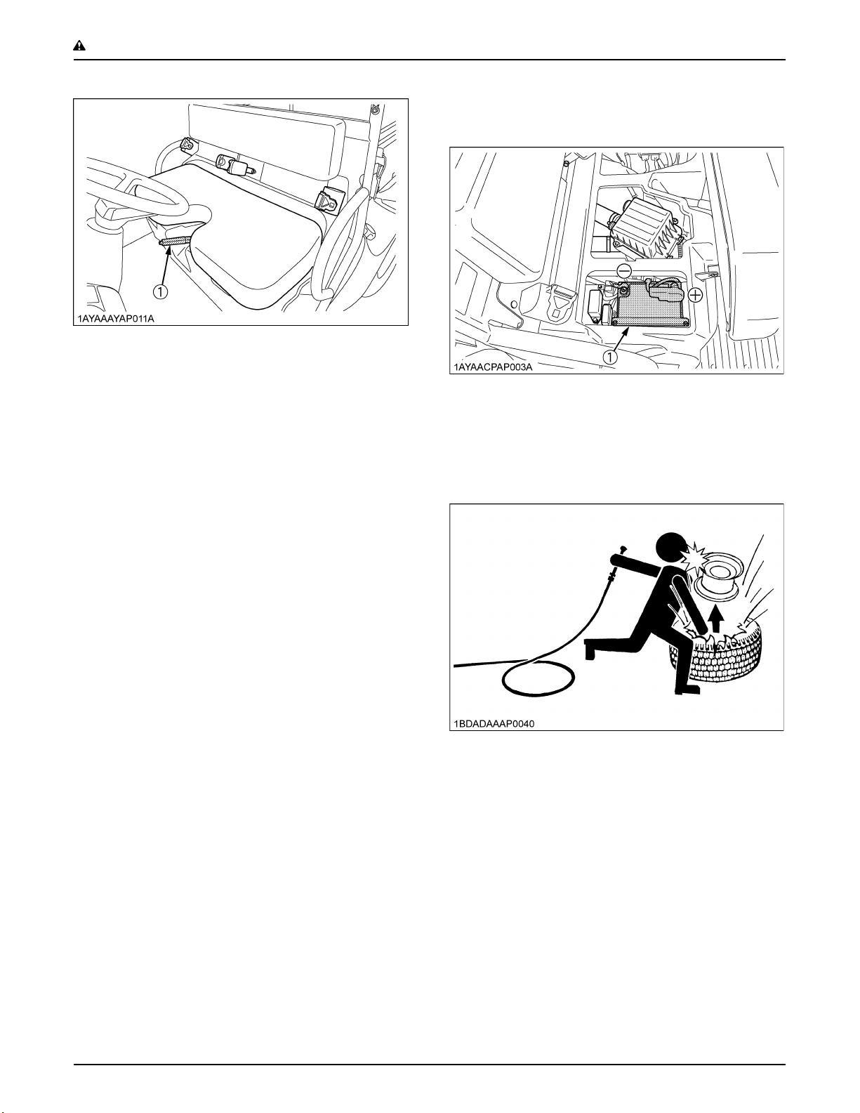
(1) Parking brake lever
8. To avoid sparks from an accidental short circuit,
always disconnect the battery's ground cable (-) first
and reconnect it last.
5. TRANSPORTING
1. Disengage power to attachment(s) when transporting
or not in use.
2. Do not tow this vehicle. Use a suitable truck or trailer
when transporting on public roads.
3. Use extra care when loading or unloading the vehicle
into a trailer or truck.
6. SERVICING THE VEHICLE
Before servicing the vehicle, park it on a firm, flat and level
surface, set the parking brake, lower all implements to the
ground, place the range gear shift lever in neutral, stop the
engine and remove the key.
1. Allow the vehicle time to cool off before working on or
near the engine, muffler, radiator, etc.
2. Always stop the engine before refueling. Avoid spills
and overfilling.
3. Do not smoke when working around battery or when
refueling. Keep all sparks and flames away from
battery and fuel tank. The battery presents an
explosive hazard, because it gives off hydrogen and
oxygen especially when recharging.
4. Before "jump starting" a dead battery, read and follow
all of the instructions. (See "JUMP STARTING" in
"OPERATING THE ENGINE" section.)
5. Keep first aid kit and fire extinguisher handy at all
times.
6. Disconnect the battery's ground cable before working
on or near electric components.
7. To avoid the possibility of battery explosion, do not use
or charge the refillable type battery if the fluid level is
below the LOWER (lower limit level) mark. Check the
fluid level regularly and add distilled water as required
so that the fluid level is between the UPPER and
LOWER marks.
(1) Battery
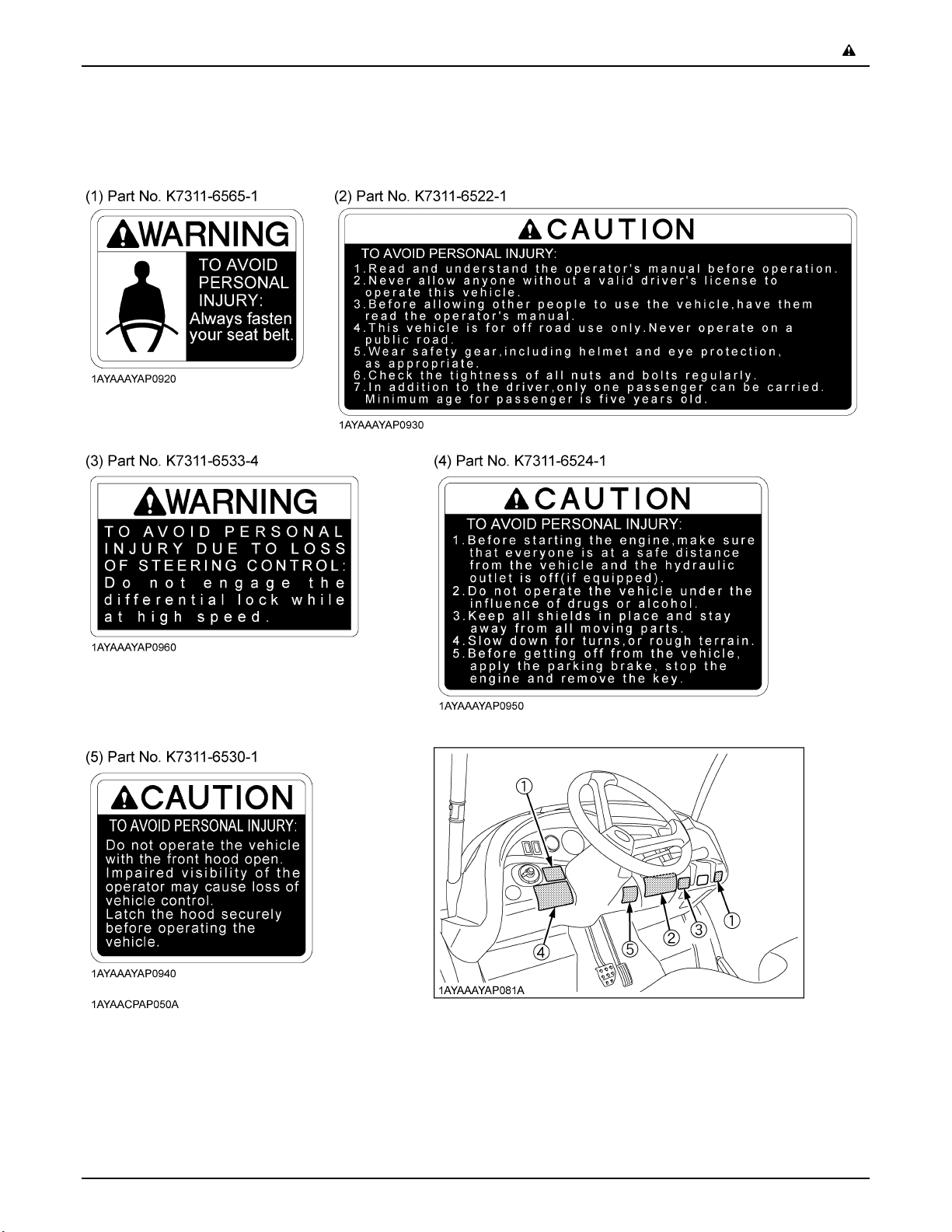
9. Do not attempt to mount a tire on a rim. This should be
done by a qualified person with the proper equipment.
10.Always maintain the correct tire pressure. Do not
inflate tires above the recommended pressure shown
in the operator's manual.
11.Securely support the vehicle when changing wheels.
12.Make sure that wheel bolts have been tightened to the
specified torque.
13.Waste products such as used oil, fuel, hydraulic fluid,
and batteries, can harm the environment, people, pets
and wildlife. Please dispose properly.
See your local Recycling Center or KUBOTA Dealer to
learn how to recycle or get rid of waste products.
Page 13
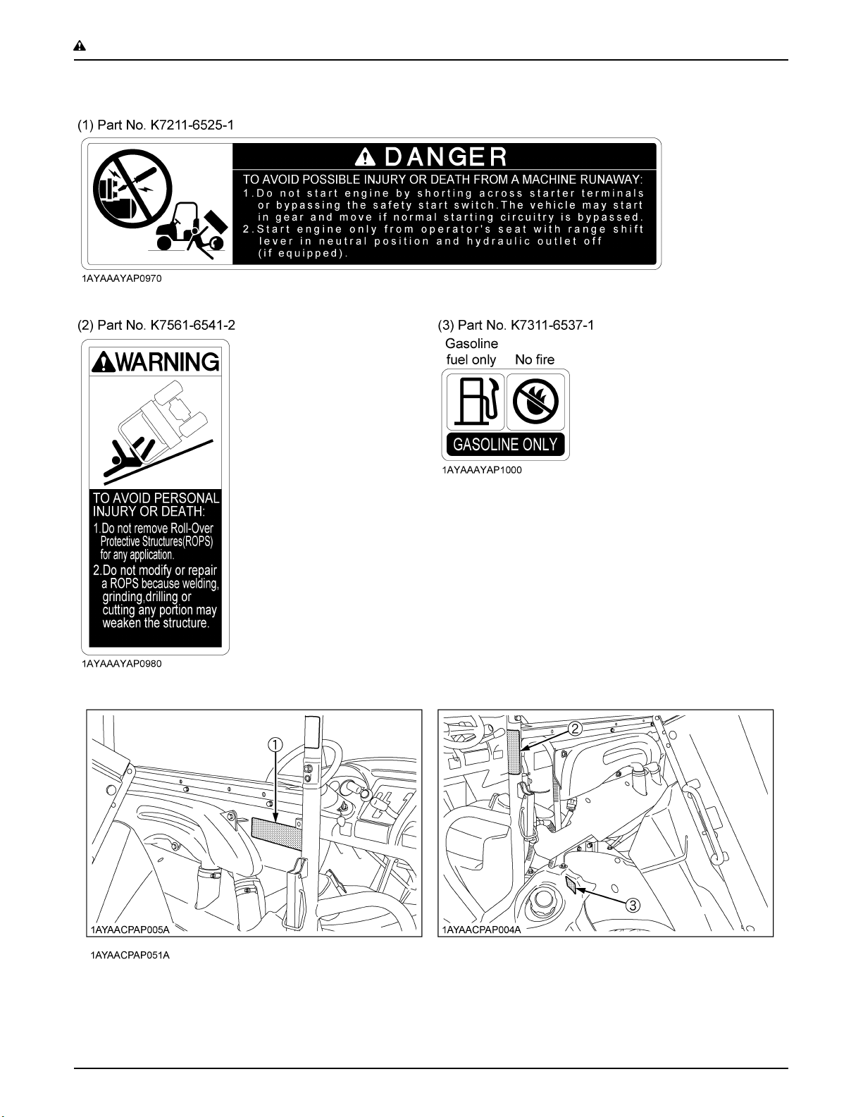
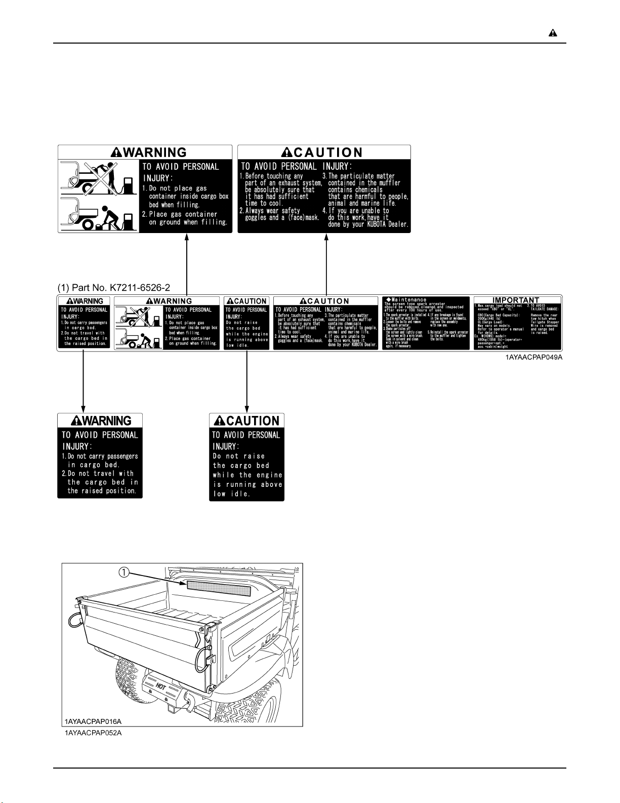
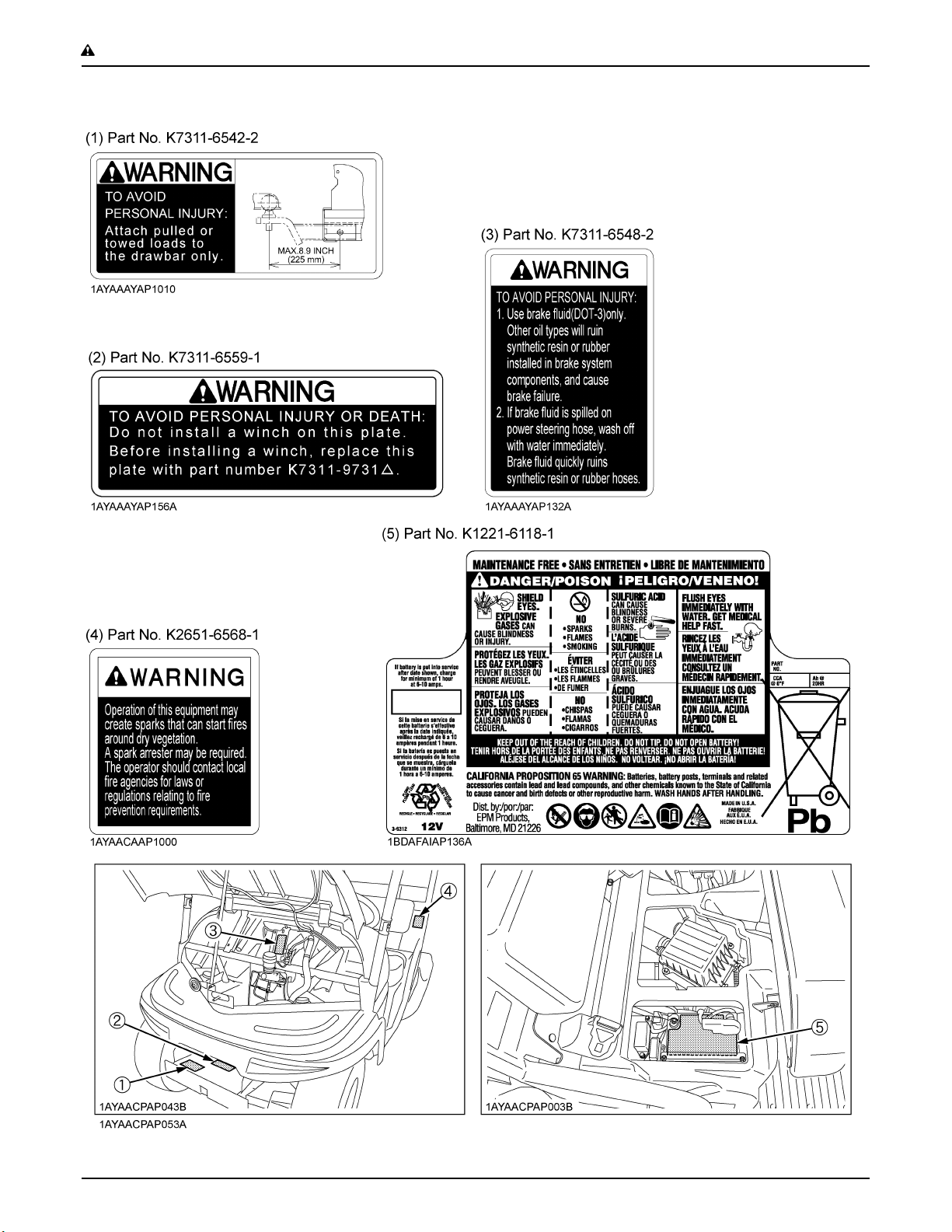
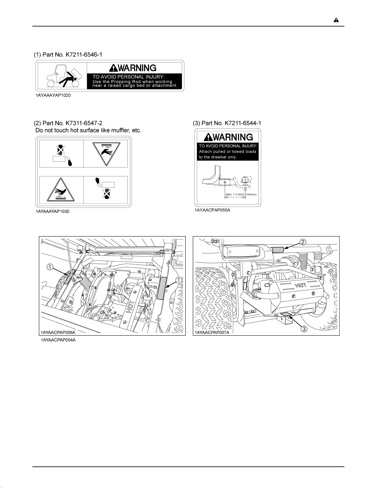
7. DANGER, WARNING AND CAUTION LABELS
-5SAFE OPERATION
Page 14
SAFE OPERATION-6
Page 15
-7SAFE OPERATION
Page 16
SAFE OPERATION-8
Page 17
-9SAFE OPERATION
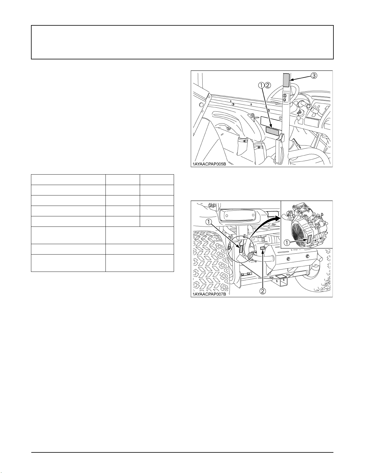
8. CARE OF DANGER, WARNING AND CAUTION LABELS
1. Keep danger, warning and caution labels clean and free from obstructing material.
2. Clean danger, warning and caution labels with soap and water, dry with a soft cloth.
3. Replace damaged or missing danger, warning and caution labels with new labels from your local KUBOTA Dealer.
4. If a component with danger, warning and caution label(s) affixed is replaced with new part, make sure new label(s)
is(are) attached in the same location(s) as the replaced component.
5. Mount new danger, warning and caution labels by applying on a clean dry surface and pressing any bubbles to outside
edge.
Page 18

Page 19
SERVICING OF VEHICLE
Your dealer is interested in your new vehicle and has the
desire to help you get the most value from it. After reading
this manual thoroughly, you will find that you can do some
of the regular maintenance by yourself.
However, when in need of parts or major service, be sure
to see your KUBOTA Dealer.
For service, contact the KUBOTA Dealership from which
you purchased your vehicle or your local KUBOTA
Dealer.
When in need of parts, be prepared to give your dealer
vehicle, engine, transmission and ROPS serial numbers.
Locate the serial numbers now and record them in the
space provided.
1SERVICING OF VEHICLE
Type Serial No.
Vehicle
Engine
Transmission
ROPS
Product Identification
Number
Date of Purchase
Name of Dealer
(To be filled in by purchaser)
C Warranty
This vehicle is warranted under the Kubota Limited
Express warranty a copy of which may be obtained from
your selling dealer. No warranty shall, however, apply if
the vehicle has not been handled according to the
instruction given in the Operator's Manual even it is within
the warranty period.
C Scrapping the vehicle and its procedure
To put the vehicle out of service, correctly follow the local
rules and regulations of the country or territory where you
scrap it. If you have questions, consult your local
KUBOTA Dealer.
(1) Vehicle serial number
(2) Vehicle identification number
(3) ROPS serial number
(1) Engine serial number
(2) Transmission assy serial number
Page 20

2 SPECIFICATIONS
SPECIFICATIONS
SPECIFICATION TABLE
Model RTV400Ci
Model SUBARU GH4120
Engine
Fuel Capacity L (U.S.gals) 20 (5.3)
Transmission Continuously variable transmission (CVT)
Wheels, Drive system 4, Rear 2WD or 4WD
Differential lock Standard; hand operated with mechanical holder
Gear selection Hi-Lo range forward, neutral, reverse
Brakes
Steering Rack & Pinion
Suspension
Dimensions
Type 1 cylinder OHC, Air-cooled, EFI Gas
Displacement L (cu. in.) 0.404 (24.7)
Front / Rear Dry disk brake
Parking brake Rear wheel, hand lever
Front Independent, MacPherson strut-type
Rear Semi-independent, Multi-link
Length mm (in.) 2690 (105.9)
Width mm (in.) 1390 (54.7)
Height, overall mm (in.) 1829 (72)
Front tread centers mm (in.) 1016 (40)
Rear tread centers mm (in.) 1041 (41)
Wheelbase mm (in.) 1800 (70.9)
Ground
clearance
Turning diameter m (ft) 7 (22.9)
Max. rolling weight
(Towing Capacity)
Payload capacity kg (lbs.) 480 (1058)
Weight kg (lbs.) 565 (1246) with ATV Tires / 570 (1257) with HDWS Tires
Width mm (in.) 1032 (40.6)
Length mm (in.) 856 (33.7)
Depth mm (in.) 290 (11.4)
Cargo bed
Volume m (cu.ft.) 0.25 (9)
Bed height
(unloaded)
Max. cargo bed load kg (lbs.) 200 (441)
front axle
mm (in.)
rear axle 175 (6.9)
kg (lbs.) Rear: 500 (1102) / Front: 250 (551)
mm (in.) 810 (31.9)
205 (8.1)
Page 21
Model RTV400Ci
3SPECIFICATIONS
Front
Tires
Rear
Front deluxe guard Opt.
Body color Orange / Camo
Speedometer Opt.
Rear net Opt.
A The company reserves the right to change the specifications without notice.
A The values in "Ground clearance" and "Weight" are those of the machine equipped with the tires in the table above.
24x9-12
HDWS, 6PLY
24x11-12
HDWS, 6PLY
24x9-12
ATV, 6PLY
24x11-12
ATV, 6PLY
TRAVELING SPEEDS
Traveling speeds
km/h (mph)
Range gear
shift lever
Gear position
Low 24 (15)
High 40 (25)
Reverse 24 (15)
Page 22
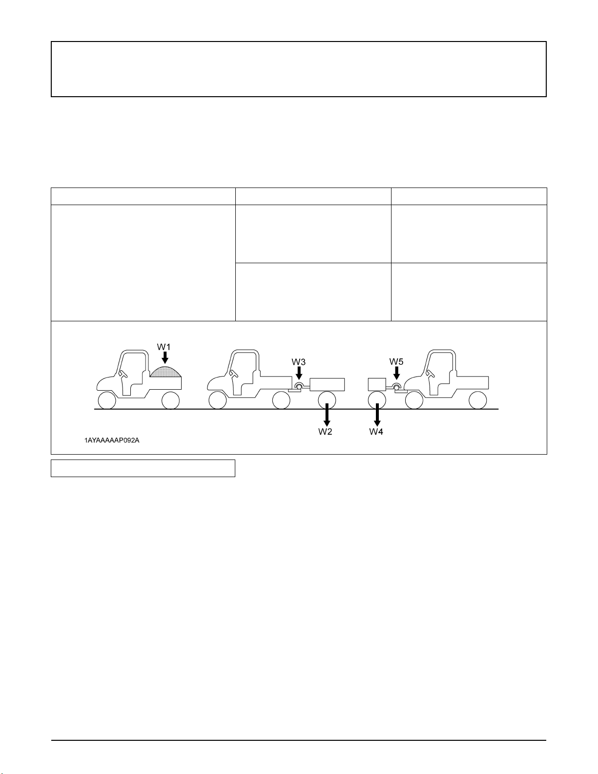
4 VEHICLE LIMITATIONS
VEHICLE LIMITATIONS
The KUBOTA Vehicle has been thoroughly tested for proper performance with implements sold or approved by KUBOTA.
Use with implements which are not sold or approved by KUBOTA and which exceed the maximum specifications listed
below, or which are otherwise unfit for use with the KUBOTA Vehicle may result in malfunctions or failures of the vehicle,
damage to other property and injury to the operator or others. [Any malfunctions or failures of the vehicle resulting from use
with improper implements are not covered by the warranty]
Max. Cargo loading weight (W1) Rear trailer hitch Front trailer hitch
Max. Cargo load should not exceed "200 kg
(441 lbs.)" or "CL".
CL = 480 kg (1058 lbs.) - (operator +
passenger + opt. + acc. + cabin) weight
Max. rolling weight (W2)
500 kg (1102 lbs.)
Max. rolling weight (W4)
250 kg (551 lbs.)
CL: Cargo Load
opt.: option
acc.: accessory
Rolling weight: Trailer weight + Cargo Load
A Above mentioned specifications are based on level ground condition.
Max. tongue weight (W3)
50 kg (110 lbs.)
Max. tongue weight (W5)
50 kg (110 lbs.)
Page 23
5INSTRUMENT PANEL AND CONTROLS
INSTRUMENT PANEL AND CONTROLS
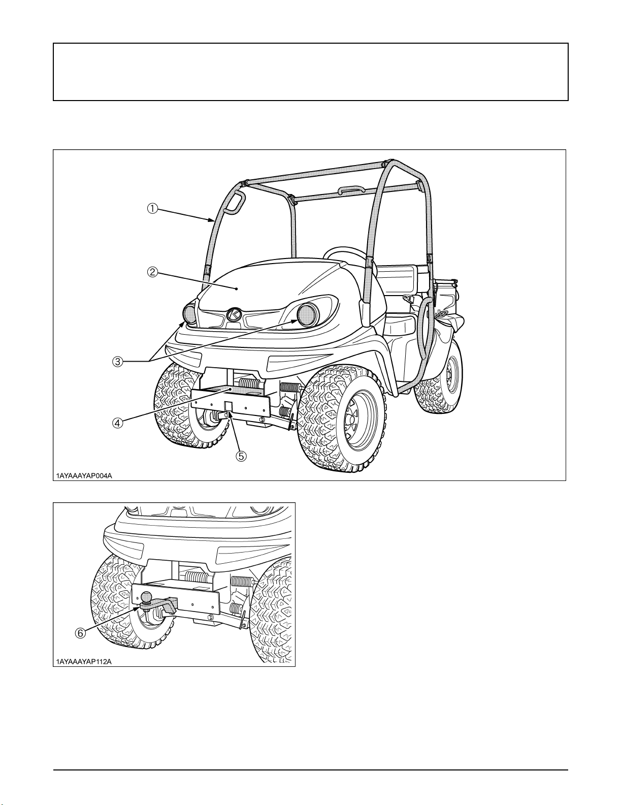
LOCATION OF PARTS
ILLUSTRATED CONTENTS
(1) ROPS............................................................. --
(2) Front hood...................................................... 37
(3) Headlights...................................................... 15
(4) Winch mount bracket (if equipped)................. 32
(5) Front trailer hitch bracket................................ 31
(6) Front trailer hitch (if equipped)........................ 31
Page 24
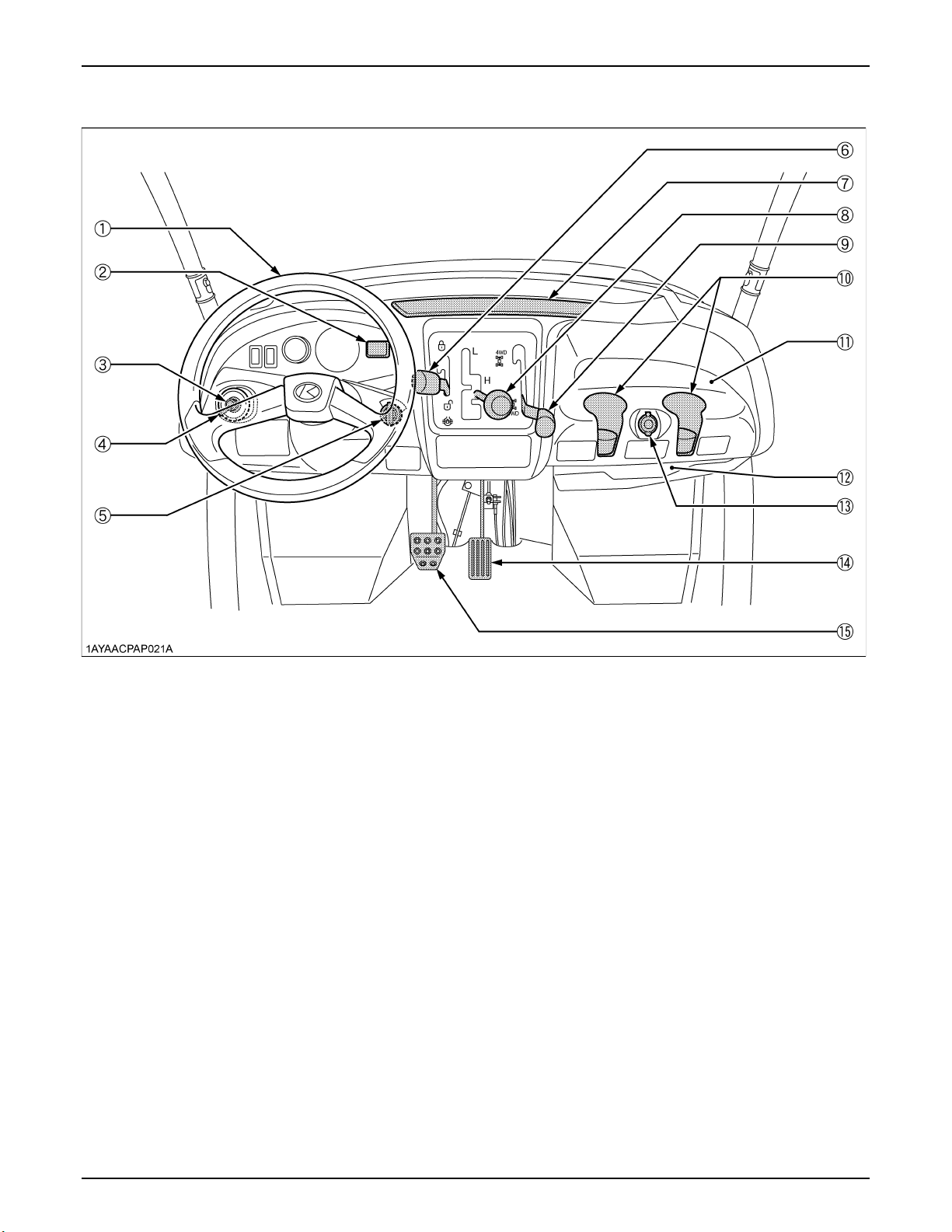
6 INSTRUMENT PANEL AND CONTROLS
ILLUSTRATED CONTENTS
(1) Steering wheel................................................. --
(2) Hourmeter........................................................ 20
(3) Horn button...................................................... 15
(4) Head light switch.............................................. 15
(5) Key switch........................................................ --
(6) Differential lock lever........................................ 21
(7) Easy Checker(TM)........................................... 19
(8) Range gear shift lever...................................... 16
(9) 4WD lever........................................................ 17
(10) Cup holder...................................................... --
(11) Glove box....................................................... --
(12) Operator's manual holder............................... --
(13) 12V accessory plug........................................ 21
(14) Speed control pedal....................................... 17
(15) Brake pedal.................................................... 16
Page 25
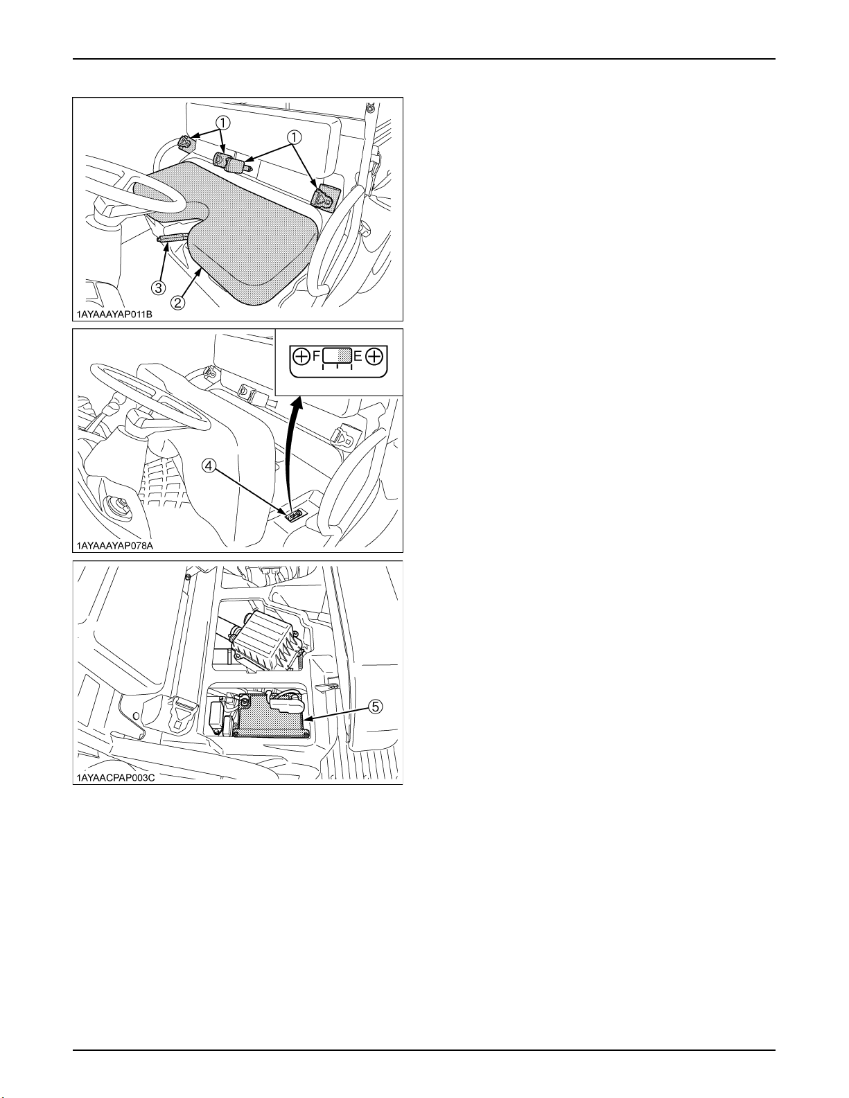
7INSTRUMENT PANEL AND CONTROLS
ILLUSTRATED CONTENTS
(1) Seat belts....................................................... 14
(2) Seat............................................................... 38
(3) Parking brake lever........................................ 20
(4) Fuel gauge..................................................... 19
(5) Battery........................................................... --
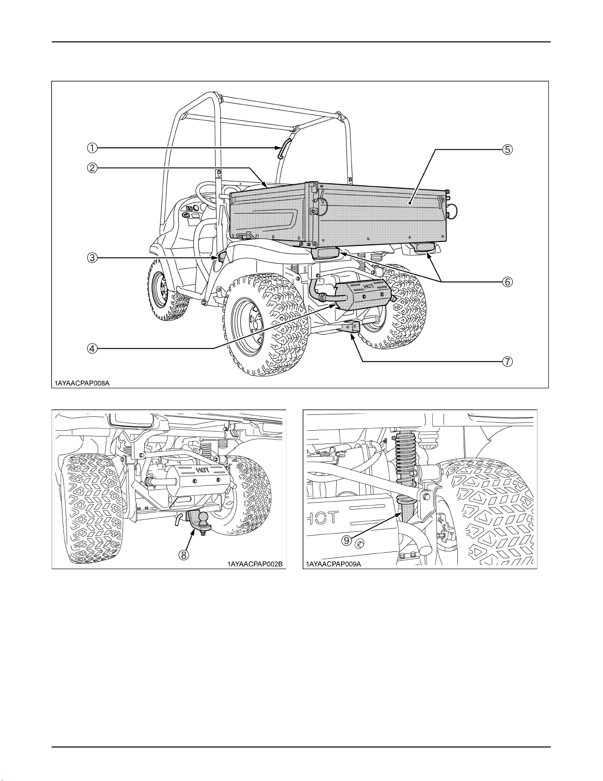
Page 26
8 INSTRUMENT PANEL AND CONTROLS
ILLUSTRATED CONTENTS ILLUSTRATED CONTENTS
(1) Handgrip.......................................................... -- (5) Tailgate............................................................ 27
(2) Cargo bed........................................................ 26 (6) Tail lamp........................................................... --
(3) Fuel tank cap.................................................... -- (7) Rear trailer hitch bracket................................... 31
(4) Muffler.............................................................. -- (8) Rear trailer hitch (if equipped)......................... 31
(9) Rear shock absorber........................................ 30
Page 27
PRE-OPERATION CHECK
DAILY CHECK
To prevent trouble from occurring, it is important to know
the condition of the vehicle well. Check it before starting.
To avoid personal injury:
A Be sure to check and service the vehicle on a
level surface with the engine shut off and the
parking brake "ON" and implement lowered to
the ground if equipped.
Check item
- Walk around inspection
- Check engine oil level
- Check transmission fluid level
- Check brake fluid level
- Check brake
- Check parking brake
- Check indicators, gauges and meters
- Check lights
- Check seat belt and ROPS
- Check front and drive joint boots
- Check tire inflation pressure
- Refuel
(See "DAILY CHECK" in "PERIODIC SERVICE" section.)
- Care of danger, warning and caution labels
(See "DANGER, WARNING AND CAUTION LABELS" in
"SAFE OPERATION" section.)
9PRE-OPERATION CHECK
Page 28
10 OPERATING THE ENGINE
OPERATING THE ENGINE
STARTING THE ENGINE
To avoid personal injury:
A Read "SAFE OPERATION" in the front of this
manual.
A Read the danger, warning and caution labels
located on the vehicle.
A To avoid the danger of exhaust fume
poisoning, do not operate the engine in a
closed building without proper ventilation.
A Never start engine while standing on ground.
Start engine only at the operator's seat.
A Make it a rule to set the range gear shift lever to
the "NEUTRAL" position.
A Do not use starting fluid to aid engine starting.
A To protect the battery and the starter, make sure that
the starter is not continuously turned for more than 10
seconds.
If the engine dose not start, allow 60-second cool
down period between start attempts.
1. Make sure the parking brake is applied.
(1) Parking brake lever (A) Pull to "PARK"
A The brake indicator light comes on while parking brake
is applied and goes off when it is released.
(1) Brake indicator light
Page 29

2. Set the range gear shift lever to the
"NEUTRAL" position.
(1) Range gear shift lever (L) LOW Range
(H) HIGH Range
(N) "NEUTRAL" POSITION
(R) "REVERSE"
11OPERATING THE ENGINE
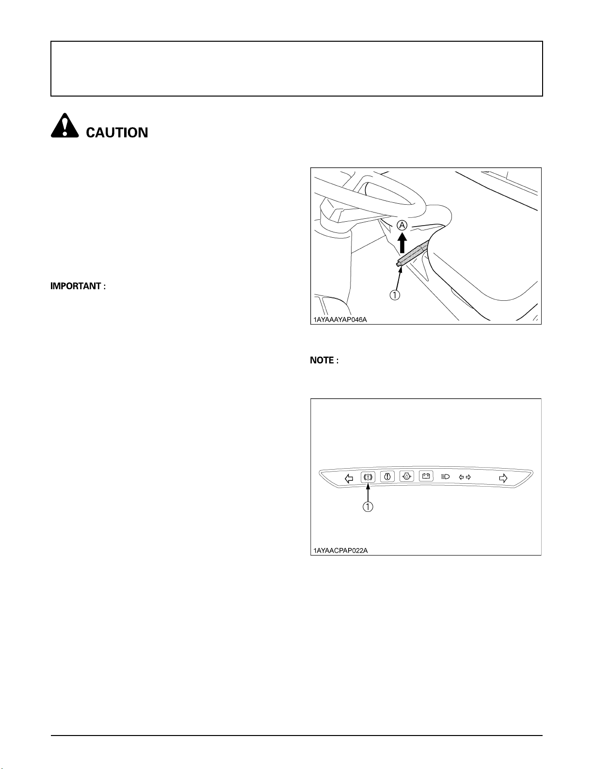
C Check Easy Checker(TM) Lamps:
1. When the key is turned "ON", lamps(2)(3)(4) should
come on. If trouble should occur at any location while
the engine is running, the warning lamp corresponding
to that location comes on.
2. The brake indicator light(1) comes on.
(1) While brake is applied and goes off when it is
released.
(2) When the brake fluid is below the "MIN" mark.
(Add the brake fluid to the "MAX" mark.)
(See "Checking Brake Fluid Level" in "DAILY
CHECK" in "PERIODIC SERVICE" section.)
3. Insert the key into the key switch and
turn it "ON".
( ) "OFF" (Engine-Stop)
( ) "ON" (Engine-Run)
( ) "START" (Engine-Start)
(1) Brake indicator light
(2) Engine diagnostic light
(3) Engine oil pressure light
(4) Electrical charge light
A Daily checks with the Easy Checker(TM) only, are not
sufficient. Never fail to conduct daily checks carefully
by referring to "DAILY CHECK" in "PERIODIC
SERVICE" section.
A For further details of Easy Checker(TM), see "Easy
Checker(TM)" in "CHECK DURING DRIVING" in
"OPERATING THE VEHICLE" section.
4. Turn the key to the "START" position
and release when the engine starts.
A As safety function, the engine will not start unless the
range gear shift lever is in the "NEUTRAL" position.
Page 30

OPERATING THE ENGINE12
BCold Weather Starting
When the ambient temperature is below 0 (32 ), the
engine is very cold. If the engine fails to start after 10
seconds, turn off the key for 30 seconds. Then repeat
steps 3 and 4. To protect the battery and the starter, make
sure that the starter is not continuously turned for more
than 10 seconds.
If it is difficult to start the engine, step on the speed control
pedal slightly.
It is likely to occur engine stalling without its warming up.
In this case re-start engine with depressing speed control
pedal approximately 1/4.
STOPPING THE ENGINE
1. Park the vehicle on a firm, flat and level surface.
2. After slowing the engine to idle, place the range gear
shift lever in neutral and set the parking brake.
3. Turn the key to "OFF".
4. Remove the key.
WARMING UP
To avoid personal injury:
A Be sure to set the parking brake during warm-
up.
A Be sure to set the range shift lever to the
"NEUTRAL" position.
For 5 minutes after engine start-up, allow the engine to
warm up without applying any load. This is to allow oil to
reach every engine part. If load should be applied to the
engine without this warm-up period, trouble such as
seizure, breakage or premature wear may develop.
Page 31

JUMP STARTING
To avoid personal injury:
A Battery gases can explode. Keep cigarettes,
sparks, and flames away from battery.
A If vehicle battery is frozen, do not jump start
engine.
A Do not connect other end of negative jumper
cable to negative terminal of vehicle battery.
A The parts such as the muffler may be hot. Be
careful not to get burned in connecting jumper
cables.
When jump starting the engine, follow the instructions
below to safely start the engine.
1. Bring helper vehicle with a battery of the same voltage
as the disabled vehicle within easy cable reach. "THE
VEHICLES MUST NOT TOUCH".
2. Engage the parking brake of both vehicles and put the
shift lever in neutral. Shut the engine off.
3. Put on safety goggles and rubber gloves.
4. Ensure the vent caps are securely in place. (if
equipped)
5. Attach the red clamp to the positive (red, (+) or pos.)
terminal of the dead battery and clamp the other end
of the same cable to the positive (red, (+) or pos.)
terminal of the helper battery.
6. Clamp the other cable to the negative (black, (-) or
neg.) terminal of the helper battery.
7. Clamp the other end to the engine block or frame of
the disabled vehicle as far from the dead battery as
possible.
8. Start the helper vehicle and let its engine run for a few
moments. Start the disabled vehicle.
9. Disconnect the jumper cables in the exact reverse
order of attachment. (Steps 7, 6 and 5).
13OPERATING THE ENGINE
(1) Dead battery
(2) Jumper cables
(3) Engine block or frame
(4) Helper battery
A This vehicle has a 12 volt negative (-) ground starting
system.
A Use only same voltage for jump starting.
A Use of a higher voltage source could result in severe
damage to vehicle's electrical system.
Use only matching voltage source when "Jump
starting" a low or dead battery.
Page 32

14 OPERATING THE VEHICLE
OPERATING THE VEHICLE
OPERATING NEW VEHICLE
How a new vehicle is handled and maintained determines
the life of the vehicle.
A new vehicle just off the factory production line has been,
of course, tested, but the various parts are not
accustomed to each other, so care should be taken to
operate the vehicle for the first 50 hours at a slower speed
and avoid excessive work or operation until the various
parts become "broken-in." The manner in which the
vehicle is handled during the "breaking-in" period greatly
affects the life of your vehicle. Therefore, to obtain the
maximum performance and the longest life of the vehicle,
it is very important to properly break-in your vehicle. In
handling a new vehicle, the following precautions should
be observed.
BDo not Operate the Vehicle at Full Speed
for the First 50 Hours
A Do not start quickly nor apply the brakes suddenly.
A In winter, operate the vehicle after fully warming up the
engine.
A Do not run the engine at speeds faster than
necessary.
A On rough roads, slow down to suitable speeds.
Do not operate the vehicle at fast speed. The above
precautions are not limited only to new vehicles, but to
all vehicles. But it should be especially observed in the
case of new vehicles.
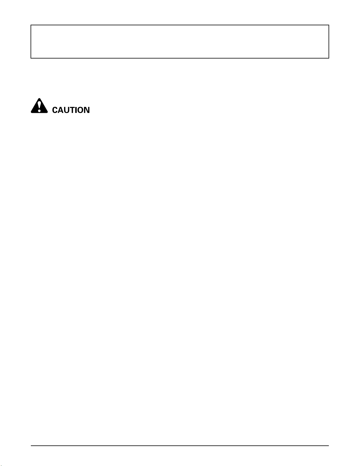
STARTING
1. Fasten the seat belt.
BSeat Belt
To avoid personal injury:
A Seat belts reduce injury. Always wear your seat
belts. The lap-style seat belts may not provide
adequate protection for small children. Special
care is recommended when carrying a child
passenger.
To avoid personal injury:
A Always use the seat belts when operating and
riding in the vehicle.
Adjust the seat belts for proper fit and connect the buckle.
This seat belt is an auto-locking retractable type.
BChanging Lubricating Oil for New
Vehicles
The lubricating oil is especially important in the case of a
new vehicle. The various parts are not "broken-in" and are
not accustomed to each other. Small pieces of metal grit
may develop during the operation of the vehicle; and this
may wear out or damage the parts. Therefore, care should
be taken to change the lubricating oil a little earlier than
would ordinarily be required. For further details of change
interval hours, see "MAINTENANCE" section.
(1) Seat belt
Page 33

15OPERATING THE VEHICLE
2. Selecting light switch position.
BHead Light Switch
The head light switch is operative when the key switch is
in the "ON" position.
Turn on the key switch and turn the head light switch to
the "ON" position.
Turn the head light switch to the "OFF" position to turn off
the head light.
BHorn Button
The horn switch is operative when the key switch is in
either the "ON" or "OFF" position.
The horn will sound when the horn button is pressed.
(1) Horn button
(1) Head light switch Head lights "ON"
Head lights "OFF"
A Turning the head light switch to the "ON" position
causes the following lamps to light simultaneously.
(1) Tail lights (lamps at the rear portions of the
vehicle)
A Do not allow the headlights to remain on when idling.
Page 34

OPERATING THE VEHICLE16
3. Checking the brake pedal.
BBrake Pedal
To avoid personal injury:
A If the operator suddenly brakes, an accident
may occur due to loss of control or the shifting
forward of heavy loads.
A When driving on icy, wet or loose surface,
make sure the vehicle is correctly ballasted to
avoid skidding and loss of steering control.
Operate at reduced speed.
The brake pedal is the left pedal on the foot board.
Depress the pedal to slow or stop the vehicle.
4. Selecting the travel speed.
BRange Gear Shift Lever
To avoid personal injury:
A Avoid changing range gear shift lever when
ascending or descending a slope.
A Before ascending or descending a slope, shift
to the "L" range to control the vehicle speed.
A If you shift gears while ascending or
descending a slope, be prepared to use the
brake to maintain control.
A Operate in reverse at slow speeds to maintain
control.
1. The range gear shift lever can only be shifted when
vehicle is completely stopped and the speed control
pedal is in the "NEUTRAL" position.
2. To avoid transmission and shift linkage damage,
completely stop the vehicle using the brake pedal
before shifting gears.
Shift the gears with the engine running at idling speed.
3. Select proper gear and engine speed depending on
the type of job.
4. Before dismounting vehicle, shift the range gear shift
lever to the "NEUTRAL" position and apply parking
brake.
(1) Brake pedal
(1) Range gear shift lever (L) LOW Range
(H) HIGH Range
(N) "NEUTRAL" POSITION
(R) "REVERSE"
Page 35

17OPERATING THE VEHICLE
A Do not force the range gear shift lever. If it is difficult to
shift the lever into "L", or "H" on slopes, be sure to
apply the parking brake before starting the procedure.
(1) Slightly depress the speed control pedal to rotate
the gears inside of transmission.
(2) Release the speed control pedal to the
"NEUTRAL" position.
A An accident may occur with erratic shifting operation.
A Improper range gear shift lever position will cause the
vehicle to momentarily coast on slopes.
B4WD Lever
To avoid personal injury:
A Do not engage the front wheel drive when
traveling at road speed.
A When driving on icy, wet or loose surfaces,
make sure the vehicle is correctly ballasted to
avoid skidding and loss of steering control.
Operate at reduced speed and engage front
wheel drive.
A An accident may occur if the vehicle is
suddenly braked, such as by heavy towed
loads shifting forward causing loss of control.
A The braking characteristics are different
between 2 and 4 wheel drive. Be aware of the
difference and use carefully.
C Front wheel drive is effective for the following
jobs:
1. When greater pulling force is needed, such as working
in a wet field, when pulling a trailer, or when working
with a front-end blade.
2. When working in sandy soil.
3. When working on snow-covered terrains.
5. Unlock the parking brake and start
slowly.
BParking Brake Lever
To release the parking brake, depress the brake pedal,
push release button and push down parking brake lever.
Make sure that indicator in the Easy Checker(TM) goes
off.
(1) 4WD lever "4WD"
"2WD"
A Use the lever to engage the front wheels with the
vehicle stopped. Shift the lever to "4WD" to engage the
front wheel drive.
A Tires will wear quickly if front wheel drive is engaged
on paved roads.
A If the 4WD lever is difficult to shift to "2WD", stop the
vehicle, turn the steering wheel in both directions and
then move the lever.
(1) Parking brake lever
(2) Release button
(A) "RELEASE"
BSpeed Control Pedal
Use the speed control pedal when traveling. Push down
on it for higher speed.
(1) Speed control pedal
Page 36

OPERATING THE VEHICLE18
STOPPING
BStopping
1. Release the speed control pedal.
2. Step on the brake pedal.
3. After the vehicle has stopped, put the range gear shift
lever in neutral, and apply the parking brake.
CHECK DURING DRIVING
BImmediately Stop the Engine if:
A The engine suddenly slows down or accelerates,
A Unusual noises are suddenly heard,
A Exhaust fumes suddenly become very dark,
While driving, check the following items to see that all the
parts are functioning normally.
(1) Easy Checker(TM)
(1) Fuel gauge
Page 37

19OPERATING THE VEHICLE
BEasy Checker(TM)
If the warning lamps in the Easy Checker(TM) come on
during operation, immediately stop the engine, and find
the cause as shown below.
Never operate the vehicle with an Easy Checker(TM)
lamp on.
( ) Brake indication light
The warning lamp in the Easy Checker(TM) comes on
if the parking brake is applied.
If the lamp is on during operation, release the parking
brake lever immediately.
If the brake fluid goes below the prescribed level, the
warning lamp in the Easy Checker(TM) will come on.
If this should happen during operation, check to see
that there is no oil leak in the brake system, and then
add oil.
(See "Checking Brake Fluid Level" in "DAILY CHECK"
in "PERIODIC SERVICE" section.)
Engine diagnostic light
If sensors malfunction, the Easy Checker(TM) will
come on. If the light is active, stop the vehicle and shut
off the engine. If the light is active after restart, consult
your local KUBOTA Dealer.
BFuel Gauge
The fuel gauge indicates the fuel level.
Be careful not to empty the fuel tank. Otherwise air may
enter the fuel system.
(1) Fuel gauge (F) "FULL"
(E) "EMPTY"
A Do not refuel over "F". Fill the tank only to the bottom
of the filler neck in the fuel tank.
Engine oil pressure light
If the oil pressure in the engine goes below the
prescribed level, the warning lamp in the Easy
Checker(TM) will come on.
If this should happen during operation, and it does not
go off when the engine is accelerated, check the level
of engine oil.
(See "Checking Engine Oil Level" in "DAILY CHECK"
in "PERIODIC SERVICE" section.)
Electrical charge light
If the alternator is not charging the battery, the Easy
Checker(TM) will come on.
If this should happen during operation, check the
electrical charging system or consult your local
KUBOTA Dealer.
Page 38

OPERATING THE VEHICLE20
BHourmeter
The hourmeter indicates in 5 digits the hours the vehicle
has been used; the last digit indicates 1/10 of an hour.
Use the hourmeter to see if your vehicle has reached the
recommended service intervals, and do your vehicle
maintenance yourself or have its maintenance done by
your local KUBOTA Dealer as necessary.
(See "SERVICE INTERVALS" in "MAINTENANCE"
section.)
PARKING
BParking Brake Lever
To avoid personal injury:
BEFORE DISMOUNTING VEHICLE
A ALWAYS APPLY THE PARKING BRAKE AND
LOWER ALL IMPLEMENTS TO THE GROUND.
Leaving transmission in gear with the engine
stopped will not prevent from rolling.
A STOP THE ENGINE AND REMOVE THE KEY.
1. Stop the vehicle on a level surface.
2. To apply the parking brake, depress the brake pedal
and pull the parking brake lever to park.
3. To release the parking brake, push the release button
and push down the parking brake lever. When the
parking brake is released, the brake indicator light in
the Easy Checker(TM) goes off.
(1) Hourmeter
(1) Parking brake lever
(2) Release button
A If the vehicle is operated with the parking brake
applied, the parking brake will be damaged.
(A) "RELEASE"
Page 39

21OPERATING THE VEHICLE
ACCESSORY
B12V Electric Outlet
The 12 volt receptacle is located on the front-panel. An
auxiliary light or other devices may be connected to this
connector.
C This outlet is activated when the key switch is in
either the "ON" or "OFF" position.
When the plug is not used, pull it out. Be careful that
leaving the plug inserted causes the battery to run out.
C Do not connect a light or other device that draws
more than 120 watts to this connector, or the
battery may discharge very rapidly or the outlet
may fail.
A Do not use as a cigarette lighter.
A Do not use when wet.
OPERATING TECHNIQUES
BDifferential Lock
To avoid personal injury due to loss of steering
control:
A Do not operate the vehicle at high speed with
differential lock engaged.
A Do not attempt to turn with the differential lock
engaged.
A Be sure to release the differential lock before
making a turn in field conditions.
If one of the rear wheels should slip, shift the differential
lock lever to the "ENGAGE" position. Both wheels will
then turn together, reducing slippage.
Differential lock is maintained while shifting the differential
lock lever to the "ENGAGE" position.
(1) 12V electric outlet
(1) Differential lock lever "ENGAGE"
"DISENGAGE"
A When using the differential lock, always slow the
engine down.
A To prevent damage to power train, do not engage
differential lock when one wheel is spinning and the
other is completely stopped.
A If the differential lock cannot be released, stop the
vehicle, turn the steering wheel alternately.
Page 40

OPERATING THE VEHICLE22
BUnfamiliar Terrain
To avoid personal injury:
A Be sure to check for hidden obstacles or
hazards before driving in a new area.
A Keep your speed down until you know the area
well.
A Use existing trails and stay away from
hazardous areas such as steep, rocky slopes
or swamps.
A Be cautious when visibility is limited, as you
may not be able to see obstacles in your path.
BDriving in Reverse
To avoid personal injury:
A Turn around, look down and behind you before
backing up to be sure there are no obstacles or
people in your way.
A Depress speed control pedal gradually and
back up cautiously.
A To stop while driving in reverse take your foot
off the speed control pedal and gradually apply
the brake.
A Do not suddenly engage the brake.
Page 41

23OPERATING THE VEHICLE
BDriving in "4WD"
To avoid personal injury:
A Do not drive in "4WD" on paved surfaces.
For the maximum traction, shift the range gear shift lever
into low range and use "4WD" on steep slopes or when
stuck in the mud, with differential locked if necessary.
BTurning the Vehicle
To avoid personal injury:
A Reduce vehicle speed before entering the turn
and maintain an even speed through the turn.
A Do not make sharp turns in order to avoid loss
of control or tipping.
Page 42

OPERATING THE VEHICLE24
BHills
To avoid personal injury:
A Do not turn sideways on a hill, or the vehicle
may roll over.
A Always go straight up hill or down hill.
A Slow down until you can get a clean view of the
other side at the crest of a hill.
A If the engine stalls on a steep slope, roll slowly
straight down, using the brake.
A Stop and look for obstacles before descending
a hill.
BTraversing Hillsides
To avoid personal injury:
A Reduce vehicles speed to prevent tipping or
loss of control.
A Do not traverse hillsides that are slippery or
covered with rocks or obstacles which may
cause you to tip over.
BSliding and Skidding
To avoid personal injury:
A Drive slowly and carefully when you are unsure
or unprepared for the surface.
A Do not apply heavy braking force or accelerate
when skidding to prevent loss of control.
A Use 4WD and maintain low speeds on areas
covered with clay, mud, ice or snow to prevent
uncontrolled skidding.
Page 43

BDriving through Water
To avoid personal injury:
A Do not drive through water whenever it is
possible.
A Drive slowly across shallow water and choose
a location to enter and exit the water where the
banks are not too steep or slippery.
A Check before entering for rocks, holes or other
obstacles that may cause overturn, get stuck or
submerged.
A Never operate the vehicle in fast flowing water
or in excess of 6 inches (152 mm) in depth.
Tires may float, making it difficult to maintain
control, and also may cause starter trouble.
A Wet brakes may reduce the stopping ability of
the vehicle. After operating in water, always
apply the brakes to dry them out.
A The brake that gets wet may wear out faster.
Check for brake wear more frequently if
operating in water often.
25OPERATING THE VEHICLE
(1) Axle cap
A Operate the vehicle in water not deeper than 6 inches
(152 mm) as the engine cooling fin could be clogged
with mud and the electrical parts could be damaged.
Muddy water could enter into the engine cooling air
inlet for the air-cooled engine.
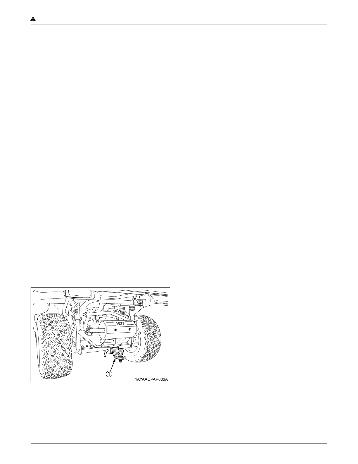
A After operating the vehicle in water, remove the rubber
plug from the CVT cover, check for accumulated water
and drain it.
(1) Engine cooling air inlet (A) Left rear tire
(1) Rubber plug
(2) CVT cover
(A) Right rear tire
Page 44

26 CARGO BED
CARGO BED
CARGO BED
BGeneral Caution
To avoid personal injury:
A Never carry passengers in the cargo bed. They can be tossed about or even thrown off causing serious
injury or death.
A Never raise the cargo bed when it is loaded.
A Driving with the cargo bed tilted may be hazardous.
Always lower the bed and latch the bed before driving.
A Be careful not to put any part of your body, such as hands or arms, between the bed and vehicle.
A Drive slowly when it is loaded.
To avoid personal injury:
A Do not raise the cargo bed while the engine is running above low idle.
BMax. Cargo Load
A Maximum Cargo Load (MCL) capacity is 200 kg (441 lbs).
A Never carry loads exceeding the Permissible Cargo Load (PCL).
A Max. Cargo load should not exceed "200 kg (441 lbs.)" or "CL".
CL = PC - (operator + passenger + opt. + acc. + cabin) weight
(CL: Cargo Load / PC: Payload Capacity / opt.: option / acc.: accessory)
[Payload capacity]
Payload capacity kg (lbs.) 480 (1058)
Page 45

27CARGO BED
BCargo Bed Tailgate
To avoid personal injury:
A Do not apply a load to the tailgate while the
tailgate is open, or the wire loop may break.
A Do not place fingers or hands between the
tailgate and the arm (latch) when closing, or
fingers or hands may be pinched.
For loading and unloading, the tailgate of the cargo bed
can be opened.
The tailgate is held level to the cargo bed floor with wire
loops.
Do not move the vehicle with the tailgate fully lowered.
In a fully lowered position, the tailgate may obstruct the
vehicle tail lamps and damage them by swinging motion.
1. Raise the arms (latch) at each end of the tailgate and
open the tailgate.
2. Close the tailgate by lifting it and pushing it firmly
closed. Push the arms (latch) down to make sure the
latches stay securely closed.
A TO AVOID TAILGATE DAMAGE:
Remove the rear trailer hitch when wire loop is
removed and cargo bed is raised.
(1) Tailgate
(2) Arm (latch)
(3) Wire loop
Page 46

CARGO BED28
BRaising and Lowering the Cargo Bed
To avoid personal injury;
A Make sure the vehicle is on a firm, level surface
and the parking brake is applied before raising
the cargo bed and securing the cargo bed in the
raised position.
A A loaded cargo bed can be very heavy. Never
raise the cargo bed when it is loaded. Unload
the cargo bed before raising it by hand.
1. Park the vehicle on a flat surface.
2. Empty the cargo bed by hand.
3. Release the latches on both sides and then raise the
cargo bed with the hand grip.
6. Release the safety support from the latch slot by
pulling up on the middle of the support.
7. Put the safety support into the support holder.
(1) Support holder
8. Slowly lower the cargo bed onto the frame and set the
latches on both sides.
(1) Latch
(2) Hand grip
(A) "LOCK"
(B) "RELEASE"
(C) "RAISE"
4. Push the safety support into the latch slot to lock when
the cargo is fully raised.
(1) Safety support
(2) Latch slot
5. To lower the cargo bed, raise the cargo bed slightly
using the handgrip.
Page 47

TIRES AND WHEELS
29TIRES AND WHEELS
TIRES
To avoid personal injury:
A Do not attempt to mount a tire on a rim. This
should be done by a qualified person with the
proper equipment.
A Always maintain the correct tire pressure.
Do not inflate tires above the recommended
pressure shown in the operator's manual.
A Do not use tires other than those approved by
KUBOTA.
BInflation Pressure
Though the tire pressure is factory-set to the prescribed
level, it naturally drops slowly in the course of time. Thus,
check it everyday and inflate as necessary.
Tire sizes Inflation Pressure
24 x 9 - 12 HDWS,
Front
24 x 11 - 12 HDWS,
Rear
24 x 9 - 12 ATV,
Front
24 x 11 - 12 ATV,
Rear
97 kPa
(0.97 kgf/cm , 14 psi)
BTire Type and Use
C Heavy duty work site tire
C All terrain vehicle tire
(1) Ground (A) "INSUFFICIENT"
(B) "NORMAL"
(C) "EXCESSIVE"
Page 48

TIRES AND WHEELS30
WHEELS
To avoid personal injury:
A Support vehicle securely on stands before
removing a wheel.
A Never operate vehicle with loose wheel bolts.
A When re-fitting a wheel, tighten the bolts to the
following torques then recheck after driving the vehicle
200 m (200 yards) and thereafter according to service
interval.
SHOCK ABSORBERS
BRear Shock Absorber Spring Adjustment
To avoid personal injury:
A Be sure to work on a firm, flat and level surface
with the engine shut off and parking brake
"ON".
A Keep the position of the left and right rear
shock absorber equal.
Uneven adjustment can cause poor handling
and loss of control, which could lead to an
accident.
The spring adjusting sleeves on the rear shock absorbers
have 5 positions so that the springs can be adjusted for
different riding and loading conditions.
For adjusting the rear shock absorber springs, turn the
adjusting sleeves on the shock absorbers to the desired
position with the hook wrench.
[Rear shock absorber position]
Position Spring Feeling Load
1 Stronger Hard Heavy
(1) Torque wheel bolts to 108.4 to 121.9 N-m
(11 to 12.4 kgf-m) (80 to 90 lbf-ft)
2
3 (default)
4
5 Weaker Soft Light
A If you feel any difficulty in the adjustment, consult your
local KUBOTA dealer.
The rear shock absorber spring is adjusted to third
position (default) in the figure below.
(A) Rear shock absorber
(B) Adjusting sleeve (Turn here with a hook wrench.)
Page 49

TOWING AND TRANSPORTING
31TOWING AND TRANSPORTING
TOWING AND TRANSPORTING
BRear Trailer Hitch
[if equipped]
To avoid personal injury:
A Always tow a load slowly enough to maintain
control and avoid tipping.
A To provide adequate braking ability and
traction, do not tow a load unless vehicle cargo
bed is loaded or attachment is installed.
A Attach a trailer to the trailer hitch only.
The rear trailer hitch load is listed in the "VEHICLE
LIMITATIONS" section. When towing other equipment,
use a safety chain.
BFront Trailer Hitch
[if equipped]
To avoid personal injury:
A Do not tow this vehicle unless all the functions
of the vehicle are properly working, since the
malfunction of steering operation or braking
may cause an accident.
Use the front trailer hitch for greater maneuverability in
confined areas such as a barn.
The front trailer hitch load is listed in the "VEHICLE
LIMITATIONS" section.
(1) Rear trailer hitch (if equipped)
(2) Hitch pin (if equipped)
(1) Front trailer hitch (if equipped)
(2) Hitch pin (if equipped)
Page 50

TOWING AND TRANSPORTING32
BWinch Mount Bracket
[if equipped]
Mounting the optional winch always requires reading the
instruction manual attached to the winch thoroughly
before using it.
(1) Winch mount bracket (if equipped)
Page 51

33MAINTENANCE
MAINTENANCE
To avoid personal injury and vehicle damage:
A Be sure you have sufficient knowledge, experience, the proper replacement parts and tools before you
attempt any vehicle maintenance task.
A If you don't have the knowledge and equipment which are necessary to perform the maintenance task,
consult your local KUBOTA Dealer.
A Have your local KUBOTA Dealer perform inspection items which are marked *6 in the chart below.
SERVICE INTERVALS
A The jobs indicated by must be done after the first 50 hours of operation.
A Changing engine oil and engine oil filter indicated by must be done after the first 20 hours of operation.
*1 The initial 50 hours should not be a replacement cycle.
*2 Air cleaner should be cleaned more often in dusty conditions than in normal conditions.
*3 Every 1000 hours or every 1 year whichever comes faster.
*4 Replace if any deterioration (crack, hardening, scar, or deformation) or damage occurred.
*5 Every 2000 hours or every 2 years whichever comes faster.
*6 Consult your local KUBOTA Dealer for this service.
*7 When the battery is used for less than 100 hours per year, check the battery condition by reading the indicator annually.
*8 Vehicles subjected to extreme operations and/or conditions must be inspected and serviced more frequently.
*9 Replace only if necessary.
*10 The initial 20 hours should not be a replacement cycle.
Extreme Conditions:
1. Frequent or prolonged operations in dusty environments
2. Prolonged low speed operations
3. Extended idle time
4. Frequent short trips which do not let the engine warm up (especially in cold weather)
A GASOLINE ENGINE EMISSION RELATED MAINTENANCE INSTRUCTIONS:
1. Non-warranty maintenance, repair, or replacement of the emission control devices and systems should be performed
by a qualified repair establishment or individual which has the experience and equipment to perform such work.
See the Emissions Warranty Statement.
2. To ensure the best quality and reliability, use new KUBOTA Genuine parts or their equivalents for repair and
replacement, whenever you have maintenance done.
No. Items
1 Greasing Apply
Engine start
2
system
3 Wheel bolt torque Check
Air cleaner
4
element (Engine)
Check
Clean
Replace
Indication of Hour Meter
20 50 100 150 200 250 300 350 400 450 500 550 600 650 700
After
700 hrs
every
50 hrs
every
50 hrs
every
100 hrs
every
100 hrs
every
1000
hrs or
1 year
Ref.
Page
45
46
46 *1
48 *2
60 *3
Page 52

34 MAINTENANCE
No. Items
Clean
Air cleaner
5
element (CVT)
6 Fuel line
Carbon canister air
7
filter
8 Battery condition Check
9 Toe-in Adjust
10 Spark arrester Clean
Parking brake
11
lever
12 Engine oil filter Replace
13 Engine oil Change
Engine oil in clutch
14
case
Engine cooling air
15
inlet and Engine
cooling fin
16 CVT belt Check
17 Transmission oil Change
Spark plug
18
condition and gap
19 Brake pedal Check
20 Brake hose & pipe
21 Brake light switch Check
Intake air line
22
(Engine)
Intake air line
23
(CVT)
Replace
Check
Replace
Check
Adjust
Change
Check
Check
Check
Replace
Check
Replace
Check
Replace
Indication of Hour Meter
20 50 100 150 200 250 300 350 400 450 500 550 600 650 700
After
700 hrs
every
100 hrs
every
1000
hrs or
1 year
every
100 hrs
every
2 years
every
100 hrs
every
100 hrs
every
100 hrs
every
100 hrs
every
200 hrs
every
200 hrs
every
100 hrs
every
200 hrs
every
200 hrs
every
200 hrs
every
400 hrs
every
100 hrs
every
200 hrs
every
1 year
every
4 years
every
200 hrs
every
1 year
every
4 years
every
1 year
every
4 years
Ref.
Page
48 *2
60 *3
50 *4
62 *6
51 *9
51 *7
53
54
54
55 *10
47
55
56
57
58
49
57
60 *4
62 *6
57 *1
61 *4
62
61 *4
62
*1
*6
*8
*10
*1
*6
*1
*6
Page 53

35MAINTENANCE
No. Items
24 Tire wear Check
25 Front axle case oil Change
Engine valve
26
clearance
Engine
27
combustion
chamber
28 Brake fluid Change
Brake master
29
cylinder
(inner parts)
Engine breather
30
hose
31 Brake pad wear Check
32 Parking brake Adjust 63 *6
33 Fuse Replace 63
34 Light bulb Replace 65
Adjust
Clean
Replace
Check
Replace
20 50 100 150 200 250 300 350 400 450 500 550 600 650 700
Indication of Hour Meter
After
700 hrs
every
300 hrs
every
400 hrs
every
300 hrs
every
500 hrs
every
2 years
every
4 years
every
1 year
every
4 years
Service
as
required
Ref.
Page
58 *1
59
58
60
62 *6
62 *6
60 *4
62 *6
62 *6
Page 54

36 MAINTENANCE
LUBRICANTS AND FUEL
No. Locations Capacities Lubricants
Automobile unleaded or regular gasoline
1 Fuel 20 L (5.3 U.S.gals.)
[Filter exchanged]
2 Engine crankcase
3 Transmission case 5.4 L (1.4 U.S.gals.) KUBOTA UDT or SUPER UDT-2 fluid*
4 Front axle case 0.21 L (0.22 U.S.qts.) KUBOTA UDT or SUPER UDT-2 fluid*
Brake fluid
5
(reservoir and lines)
1.6 L (1.7 U.S.qts.)**
[Filter non-exchanged]
1.4 L (1.5 U.S.qts.)**
0.2 L (0.21 U.S.qts.)
Greasing No. of greasing points Capacity Type of grease
Battery terminal 2
Cargo bed pivot 2
Parking brake pivot 2
Range gear shift lever pivot 1
4WD lever pivot 1
Differential lock lever 1
Unleaded gasoline 87 octane or higher
Gasohol (E10 or less)
Engine oil: API Service
Classification SG, SH, SJ or higher
Above -18 (0 )...SAE10W-30
Below 0 (32 )......SAE5W-20 or 5W-30
KUBOTA DOT3 GENUINE BRAKE FLUID
Moderate amount Spray Type Grease
*KUBOTA UDT or SUPER UDT-2 fluid --- KUBOTA original transmission hydraulic fluid
**Oil amount when the oil level is at the upper level of the oil level gauge.
C Engine Oil:
Oil used in the engine should have an American Petroleum Institute (API) service classification and Proper SAE Engine
Oil according to the ambient temperatures as shown above:
C Fuel:
A Gasohol (up to 10% ethyl alcohol, 90% unleaded gasoline by volume) is approved for the engine. Other gasoline/
alcohol blends are not approved.
C Transmission oil:
To complete lubrication of the transmission, it is important that a multi-grade transmission fluid be used in this system.
We recommend the use of KUBOTA UDT or SUPER UDT-2 fluid for optimum protection and performance. (Consult
your local KUBOTA Dealer for further detail.)
Do not mix different brands or grades.
C Brake fluid:
Always use KUBOTA DOT3 GENUINE BRAKE FLUID from a sealed container. If it is not available, you should use only
DOT3 fluid as a temporary replacement from a sealed container.
However, the use of any non-KUBOTA brake fluid can cause corrosion and decrease the life of the system.
Have the brake system flushed and refilled with KUBOTA DOT3 GENUINE BRAKE FLUID as soon as possible.
A Indicated capacity of water and oil are manufacturer's estimate.
Page 55

PERIODIC SERVICE
5. Press-fit the hood into position with both hands.
To avoid personal injury:
A Do not work under any hydraulically supported
devices. They can settle, suddenly leak down,
or be accidentally lowered. If necessary to work
under vehicle or any vehicle elements for
servicing or adjustment, securely support them
with stands or suitable blocking beforehand.
HOW TO OPEN THE HOOD AND TILT THE
SEAT
To avoid personal injury from contact with moving
parts;
A Never open the operator's seat while the engine
is running.
(1) Support link
(2) Hole
37PERIODIC SERVICE
(A) "HOLD"
(B) "PUSH" (Lock)
(C) "PULL" (Unlock)
BHood
1. To open the hood, pull up the latch lever to release the
latch and open the hood.
2. Push the support link into the hole to lock when the
hood is fully raised.
(1) Support holder
(1) Latch lever
(2) Hood
3. To close the hood, hold the hood and lift up it slightly
and pull the support link to unlock.
4. Put the support link into the support holder.
(A) "RELEASE"
Page 56

PERIODIC SERVICE38
BOperator's Seat
To open the seat, raise the seat to the forward position.
(1) Operator's seat
HOW TO RAISE THE CARGO BED
To avoid personal injury:
A When servicing under raised bed, make sure
safety support is properly mounted.
A Do not touch muffler or exhaust pipes while
they are hot; Severe burns could result.
BRaising and Lowering the Cargo Bed
To avoid personal injury;
A Make sure the vehicle is on a firm, level surface
and the parking brake is applied before raising
the cargo bed and securing the cargo bed in the
raised position.
A A loaded cargo bed can be very heavy. Never
raise the cargo bed when it is loaded. Unload
the cargo bed before raising it by hand.
1. Park the vehicle on a flat surface.
2. Empty the cargo bed by hand.
3. Release the latches on both sides and then raise the
cargo bed with the hand grip.
(1) Latch
(2) Hand grip
4. Push the safety support into the latch slot to lock when
the cargo is fully raised.
(A) "LOCK"
(B) "RELEASE"
(C) "RAISE"
Page 57

(1) Safety support
(2) Latch slot
5. To lower the cargo bed, raise the cargo bed slightly
using the handgrip.
6. Release the safety support from the latch slot by
pulling up on the middle of the support.
7. Put the safety support into the support holder.
39PERIODIC SERVICE
JACK-UP POINT
To avoid personal injury, death or vehicle damage:
A Do not work under the vehicle unless it is
secured by safe stands or suitable blocking.
BFront End
Jack up at the front bumper only.
(1) Support holder
8. Slowly lower the cargo bed onto the frame and set the
latches on both sides.
(1) Front bumper
(2) Jack
(3) Wooden block
BRear End
Jack up the rear side after placing a wooden block under
the transmission bottom cover for securing the engine and
then supporting it.
Do not jack it up supporting the steel plate portion under
the transmission bottom cover directly.
(1) Transmission bottom cover
(2) Jack
(3) Wooden block
Page 58

PERIODIC SERVICE40
DAILY CHECK
For your own safety and maximum service life of the
vehicle, make a thorough daily inspection before
operating the vehicle to start the engine.
To avoid personal injury:
A Be sure to check and service the vehicle on a
flat surface with the engine shut off and the
parking brake "ON".
BWalk Around Inspection
Look around and under the vehicle for such items as loose
bolts, trash build-up, oil or coolant leaks, broken or worn
parts.
BChecking Amount of Fuel and Refueling
To avoid personal injury:
A Handle fuel carefully. If the engine is running,
do not fill the fuel tank. If engine is hot, let
engine cool several minutes before adding fuel.
Do not smoke while filling the fuel tank or
servicing the fuel system. Fill fuel tank only to
bottom of filler neck. Do not fill completely full.
The empty space in the tank allows gasoline to
expand, when it heats up. Never remove the
fuel tank cap or add fuel when the fuel tank is
hot.
Check the fuel level. Take care that the fuel tank does not
become empty.
Fuel tank capacity 20 L (5.3 U.S.gals.)
A Do not mix oil with gasoline.
Use only unleaded gasoline with an octane rating index of
87 or higher may be used.
A Use fuel within approximately 30 days after purchase
to avoid deterioration in fuel quality, or add fuel
stabilizer to keep fuel fresh and stabilized.
A Fuel blend differs from season to season for the best
seasonal engine performance. To prevent engine
performance troubles such as vapor lock or hard
starting, use fuel within the season in which the fuel is
purchased.
A Infrequent use of the engine during a season can
make fuel stale in the fuel tank of the machine. Stale
fuel condition can cause engine performance troubles
by varnish and plugged carburetor components.
A Seal the fuel storage container tightly and store it out
of sunlight and heat to prevent fuel degradation.
A Condensation in the fuel tank may occur because of
various operating or environmental conditions. To
reduce condensation and avoid affecting machine
operation, fill the fuel tank at the end of daily operation
and store fuel in the plastic container.
A Use only an approved fuel container. Use only non-
metal, portable fuel containers approved by the
Underwriter's Laboratory (U.L.) or the American
Society for Testing & Materials (ASTM). If using a
funnel, make sure it is plastic and has no screen or
filter.
A Never remove the fuel tank cap or add fuel with the
engine running. Allow the engine to cool before
refueling.
A Never add fuel to or drain fuel from the machine
indoors. Move the machine outdoors and provide
adequate ventilation.
A Clean up spilled fuel immediately. If fuel is spilled on
clothing, change clothing immediately. If fuel is spilled
near machine, do not attempt to start the engine but
move the machine away from the area of spillage.
Avoid creating any source of ignition until fuel vapors
have dissipated.
A Never store the machine or fuel container where there
is an open flame, spark, or pilot light such as on a
water heater or other appliance.
A Prevent fire and explosion caused by static electric
discharge. Static electric discharge can ignite fuel
vapors in an ungrounded fuel container.
A Never fill containers inside a vehicle or on a truck or a
trailer bed with a plastic liner. Always place containers
on the ground away from your vehicle before fueling.
Page 59

A Remove fuel-powered equipment from the truck or the
trailer and refuel it on the ground. If this is not possible,
then refuel such equipment with a portable container,
rather than from a fuel dispenser nozzle.
A Keep the nozzle in contact with the rim of the fuel tank
or container opening at all times until the fueling is
complete. Do not use a nozzle lock-open device.
A Never overfill fuel tank. Replace the fuel tank cap and
tighten securely.
A Replace all fuel container caps securely after use.
A For gasoline engines, do not use gas with methanol.
Methanol is harmful to your health and to the
environment.
A Do not use stale fuel.
A Fill fuel tank at the end of daily operation to prevent
condensation in the fuel tank.
[Use of alcohol mixed gasoline (Gasohol: E10 or
less)]
Use "gasohol" only when the ethanol additive is less than
10% of the fuel. The use of methanol additive is not
recommended. For the best results, use unleaded fuel
with a minimum of 87 octane.
41PERIODIC SERVICE
BChecking Engine Oil Level
To avoid personal injury:
A Be sure to stop the engine before checking the
oil level.
1. Park the vehicle on a flat surface and raise the cargo
bed. Shut off the engine and remove the key.
2. Allow the engine to cool for 5 minutes or more.
3. To check the oil level, draw out the dipstick, wipe it
clean, reinstall it, and draw it out again. Check to see
that the oil level lies between the 2 notches.
If the level is too low, add new oil to the prescribed
level at the oil inlet.
(See "LUBRICANTS AND FUEL" in "MAINTENANCE"
section.)
(1) Fuel tank cap
(2) Fuel tank filler neck
(3) Max. fuel level
(1) Oil inlet
(2) Dipstick
(A) Oil level is acceptable within this range.
A When using an oil of different maker or viscosity from
the previous one, remove all of the old oil.
Never mix 2 different types of oil.
A If oil level is low, do not run engine.
A Clean the area around dipstick and oil inlet before
removing or loosening them, and be careful not to
allow the dust go into the engine.
Page 60

PERIODIC SERVICE42
BChecking Transmission Fluid Level
1. Park the vehicle on a flat surface and raise the cargo
bed. Shut off the engine and remove the key.
2. Allow the engine to cool for 5 minutes or more.
3. To check the oil level, draw out the dipstick, wipe it
clean, reinstall it, and draw it out again. Check to see
that the oil level lies between the 2 notches.
If the level is too low, add new oil to the prescribed
level at the oil inlet.
(See "LUBRICANTS AND FUEL" in "MAINTENANCE"
section.)
BChecking Brake Fluid Level
To avoid personal injury:
A Never operate the vehicle, if the brake fluid is
below the "MIN" mark.
A Use only KUBOTA DOT3 GENUINE BRAKE
FLUID from a sealed container. Using other
type of oil ruins synthetic resin or rubber
installed in brake system components, and
may cause brake failure.
A Avoid contamination of the brake fluid.
Thoroughly clean area around the filler cap
before removing. Do not open the brake fluid
reservoir cap unless absolutely necessary.
A Use extreme care when filling the reservoir. If
brake fluid is spilled on power steering hose,
wash off with water immediately. Brake fluid
quickly ruins synthetic resin or rubber hoses.
1. Park the vehicle on a level ground and open the hood.
2. Check to see that the brake fluid level is between the
"MAX" and "MIN" marks.
3. If it is below the "MIN" mark, add brake fluid to the
"MAX" mark.
(1) Dipstick (A) Oil level is acceptable within this range.
A If oil level is low, do not run engine.
(1) Oil tank cap (A) "MAX"
(B) "MIN"
Page 61

43PERIODIC SERVICE
BChecking Brake Pedal
To avoid personal injury:
A Stop the engine and chock the wheels before
checking brake pedal.
1. Inspect the brake pedals for free travel, and smooth
operation.
2. Adjust if incorrect measurement is found: (See
"Checking Brake Pedal" in "EVERY 200 HOURS" in
"PERIODIC SERVICE" section.)
BChecking Parking Brake
Pull the parking brake lever to apply the brakes. With the
key switch at "ON" position, the brake indicator on the
instrument panel lights up. To release the brakes, push in
the button at the tip of the parking brake lever and tilt down
the lever.
A Make sure the brake indicator light on the Easy
Checker(TM) goes off when parking brake lever is
down.
(1) Brake pedal (A) "FREE TRAVEL"
(B) "PEDAL STROKE"
(1) Parking brake lever
(2) Release button
(A) "PULL"
(B) "RELEASE"
BChecking Gauges, Meter and Easy
Checker(TM)
1. Inspect the instrument panel for broken gauge(s),
meter(s) and Easy Checker(TM) lamps.
2. Replace if broken.
BChecking Head Light, etc.
1. Inspect the lights for broken bulbs and lenses.
2. Replace if broken.
BChecking Seat Belt and ROPS
1. Always check condition of seat belt and ROPS
attaching hardware before operating vehicle.
2. Replace if damaged.
Page 62

PERIODIC SERVICE44
BChecking Joint Boot
1. Check to see if the joint boots are not damaged.
2. If the boots are cuts, cracked or shows signs of
deterioration, consult your local KUBOTA Dealer.
(1) Joint boot
(2) Front drive shaft
(3) Tie rod
BChecking Tire Inflation Pressure
Though the tire pressure is factory-set to the prescribed
level, it naturally drops slowly in the course of time. Thus,
check it everyday and inflate as necessary.
Tire sizes Inflation Pressure
24 x 9 - 12 HDWS,
Front
24 x 11 - 12 HDWS,
Rear
24 x 9 - 12 ATV,
Front
24 x 11 - 12 ATV,
Rear
(0.97 kgf/cm , 14 psi)
97 kPa
(1) Joint boot
(2) Drive shaft
(1) Ground (A) "INSUFFICIENT"
(B) "NORMAL"
(C) "EXCESSIVE"
Page 63

EVERY 50 HOURS
BGreasing
Apply a small amount of multi-purpose grease to the
following points every 50 hours: If you operated the
vehicle in extremely wet and muddy conditions, lubricate
grease fittings more often.
45PERIODIC SERVICE
(1) Battery terminals (spray type grease)
(1) Cargo bed pivot (spray type grease)
(1) Range gear shift lever pivot (spray type grease)
(2) 4WD lever pivot (spray type grease)
(3) Differential lock lever (spray type grease)
(1) Parking brake pivot (spray type grease)
Page 64

PERIODIC SERVICE46
BChecking Engine Start System
To avoid personal injury:
A Do not allow anyone near the vehicle while
testing.
A If the vehicle does not pass the test do not
operate the vehicle.
C Preparation before testing.
1. Place all control levers in the "NEUTRAL" position.
2. Set the parking brake and stop the engine.
C Test: Range gear shift lever safety switch
1. Sit on the operator's seat.
2. Shift the range gear shift lever to "H" position.
3. Return the Speed control pedal to the "N" position.
4. Turn the key to "START" position.
5. The engine must not crank.
6. Repeat the step 2 to 5 with the range gear shift lever
at "L" and "R" each position.
7. If it cranks, consult your local KUBOTA Dealer for this
service.
EVERY 100 HOURS
BChecking Wheel Bolt Torque
To avoid personal injury:
A Never operate vehicle with a loose wheel bolts.
A Any time bolts are loosened, retighten to the
specified torque.
A Check all bolts frequently and keep them tight.
Check wheel bolts regularly especially when new. If they
are loose, tighten them as follows.
(1) Torque wheel bolts to 108.4 to 121.9 N-m
(11 to 12.4 kgf-m) (80 to 90 lbf-ft)
Page 65

BChanging Engine Oil
To avoid personal injury:
A Be sure to stop the engine before changing the
oil.
A Allow engine to cool down sufficiently, oil can
be hot and can burn.
A To Avoid Damage! Vehicles subjected to extreme
operations and/or conditions must be inspected and
serviced more frequently.
Extreme Conditions:
1. Frequent or prolonged operations in dusty
environments
2. Prolonged low speed operations
3. Extended idle time
4. Frequent short trips which do not let the engine warm
up (especially in cold weather)
(1) Oil inlet
(2) Dipstick
47PERIODIC SERVICE
(A) Oil level is acceptable within this range
A Pay special attention to the engine oil level. A rise in oil
level can be an indication of contaminates and/or
associated with frequent use where the engine does
not reach operating temperature. Monitor the oil level
during such operations. Change the oil immediately if
the oil level begins to rise.
1. Park the vehicle on a flat surface and raise the cargo
bed. Shut off the engine and remove the key.
2. To drain the used oil, remove the drain plug at the
bottom of the engine and completely drain the oil into
an oil pan.
All the used oil can be drained out easily when the
engine is still warm.
3. After draining, reinstall the drain plug.
4. Fill with the new oil up to the upper notch on the
dipstick. Check the oil level after cranking slightly.
When too much oil is added, drain out the excessive
oil.
(See "LUBRICANTS AND FUEL" in "MAINTENANCE"
section.)
[Filter exchanged]
Oil capacity
1.6 L (1.7 U.S.qts.)
[Filter non-exchanged]
1.4 L (1.5 U.S.qts.)
(1) Drain plug (A) Left rear tire
A When using an oil of different maker or viscosity from
the previous one, remove all of the old oil.
Never mix 2 different types of oil.
A If oil level is low, do not run engine.
A Clean the area around dipstick and oil inlet before
removing or loosening them, and be careful not to
allow the dust go into the engine.
Page 66

PERIODIC SERVICE48
BCleaning Engine Air Cleaner Element
1. Remove the air cleaner cover.
2. Blow compressed air to the end of the element and
inside the air cleaner with care not to allow dust into
the intake air inlet.
3. Remove the air cleaner element.
4. Clean the element:
(1) When dry dust adheres to the element, blow
compressed air from the inside, turning the
element. Pressure of compressed air must be
under 205 kPa (2.1 kgf/cm , 30 psi).
(2) When carbon or oil adheres to the element,
replace the element with new one even if it has
not been used for 1 year.
5. Replace the element:
Once yearly or after every sixth cleaning, whichever
comes first.
BCleaning CVT Air Cleaner Element
1. Remove the air cleaner cover and element.
2. Clean the element:
(1) When dry dust adheres to the element, blow
compressed air from the inside, turning the
element. Pressure of compressed air must be
under 205 kPa (2.1 kgf/cm , 30 psi).
(2) When carbon or oil adheres to the element,
replace the element with new one even if it has
not been used for 1 year.
3. Replace the element:
Once yearly or after every sixth cleaning, whichever
comes first.
(1) Cover
(2) Clamp
(3) Element
(A) Intake air inlet
(B) Element end
(C) Air cleaner inside
A The air cleaner uses a dry element, never apply oil.
A Do not run the engine with filter element removed.
A When removing and installing the element, be careful
not to allow dust into the intake air inlet.
(1) Cover
(2) Clamp
(3) Element
A The air cleaner uses a dry element, never apply oil.
A Do not run the engine with filter element removed.
Page 67

BChecking Spark Plug Condition & Gap
Remove the spark plugs, check condition, and reset the
gap or replace with new plugs as necessary.
1. Raise the cargo bed.
2. Raise the seat.
Then remove a push rivet with unlocked, and turn over
the rubber sheet.
49PERIODIC SERVICE
6. Remove plugs and check its condition.
Replace the plug if worn or reuse is questionable.
7. Inspect spark plugs for cracked porcelain, pitted
electrodes, or other wear and damage. Replace the
spark plug if necessary.
(1) Spark plug (A) Rubber sheet
(1) Push rivet
(2) Rubber sheet
A To remove push rivet:
Push the pin, and set the locked rivet to the unlocked
rivet.
A To install push rivet:
Push the pin, and set the unlocked rivet to the initial
rivet.
Then set the push rivet into the hole to install, push the
pin and set it to the locked rivet.
A Do not clean the spark plug in a machine using
abrasive grit. Some grit could remain in the spark plug
and enter the engine causing extensive wear and
damage.
Recommended spark plug NGK BR6HS
8. Check the gap using a wire feeler gauge. Adjust the
gap from 0.6 to 0.7 mm (0.024 to 0.028 in.) by carefully
bending the ground electrode.
(1) Pin (P) "PUSH"
3. Before removing spark plugs, clean the area around
the base of the plug to keep dirt and debris out of the
engine.
4. Remove the spark plug wires from spark plugs.
5. Use a spark plug wrench to remove the spark plugs.
9. Reinstall the spark plug into the cylinder head.
Tightening torque
(initial)
Retightening torque
12 to 15 N-m
(8.9 to 11 lbf-ft)
23 to 27 N-m
(17 to 19 lbf-ft)
Page 68

PERIODIC SERVICE50
BChecking Fuel Line
To avoid personal injury:
A Be sure to stop the engine and remove the key
when attempting to make the following checks
and changes.
A Never fail to check the fuel lines periodically.
The fuel lines are subject to wear and aging.
Fuel may leak out onto the running engine,
causing a fire.
The fuel line connections should be checked annually or
every 100 service hours, whichever comes first.
1. Park the vehicle on a flat surface and raise the cargo
bed.
2. The fuel line is made of rubber and ages regardless of
service period.
3. If the fuel line and clamps are found to be damaged or
deteriorated, replace them.
A When the fuel line is disconnected for maintenance or
repair, close both ends of the fuel line with a piece of
clean cloth or paper to prevent dust and dirt from
entering. In addition, particular care must be taken not
to admit dust and dirt into the fuel pump. Entrance of
even a small amount of dust or dirt cause premature
wear and malfunction of the fuel pump and injector
components.
(1) Fuel line (Carbon canister Throttle body)
(2) Hose clamp
(A) Throttle body
(1) Fuel line (Fuel pump Throttle body)
(2) Hose clamp
(3) Fuel pump with filter
(1) Fuel line (Fuel tank Throttle body)
(2) Hose clamp
(A) Throttle body
(1) Fuel line (1 way valve Carbon canister)
(2) Fuel line (3 way connector 1 way valve)
(3) Fuel line (Fuel tank 3 way connector)
(4) Fuel line (Carbon canister Throttle body)
(5) Hose clamp
(A) Carbon canister
(B) 1 way valve
(C) 3 way connector
Page 69

51PERIODIC SERVICE
BChecking Carbon Canister Air Filter
Check the carbon canister air filter every 100 hours of
operation. (more often under extremely dusty or dirty
conditions.)
To avoid personal injury:
A Stop the engine, set the parking brake and
remove the key.
1. Raise the cargo bed, and push the safety support into
the latch slot to lock.
2. Remove the cover and remove the carbon canister air
filter.
BChecking Battery Condition
To avoid the possibility of battery explosion:
For the refillable type battery, follow the
instructions below.
A Do not use or charge the refillable type battery
if the fluid level is below the LOWER (lower limit
level) mark. Otherwise, the battery component
parts may prematurely deteriorate, which may
shorten the battery's service life or cause an
explosion. Check the fluid level regularly and
add distilled water as required so that the fluid
level is between the UPPER and LOWER levels.
To avoid personal injury:
A Never remove the vent caps while the engine is
running.
A Keep electrolyte away from eyes, hands and
clothes. If you are spattered with it, wash it
away completely with water immediately and
get medical attention.
A Wear eye protection and rubber gloves when
working around the battery.
(1) Canister air filter
(2) Cover
(3) Carbon canister
3. Check to see if the carbon canister air filter is worn out,
damaged or dirty.
4. If the air filter is dirty, wash the air filter in warm water
with detergent. Then rinse the air filter thoroughly until
all traces of detergent are eliminated. Squeeze out
excess water. (do not wring.) Allow the air filter to air
dry. Do not use high pressure air to clean filter.
5. If the air filter is worn out, damaged or too dirty to wash
clean, replace it with a new one.
6. Reinstall the carbon canister air filter and secure it with
the cover.
A Operating in dusty condition may require more
frequent maintenance than above.
(A) Intake air duct
(B) Air port
The factory-installed battery is non-refillable type.
If the battery is weak, charge the battery or replace it
with new one.
A Mishandling the battery shortens the service life and
adds to maintenance costs.
The original battery is maintenance free, but needs
some servicing.
If the battery is weak, the engine will be difficult to start
and the lights will be dim. It is important to check the
battery periodically.
A When exchanging an old battery for new one, use
battery of equal specification in table below.
Battery
TYPE
U1L-10 12 25 22 300
Volts (V)
Capacity
at 20 hrs
(A.H.)
Reserve
Capacity
(min)
Cold
Cranking
Amps
Page 70

PERIODIC SERVICE52
C Battery Charging
To avoid personal injury:
A When the battery is being activated, hydrogen
and oxygen gases in the battery are extremely
explosive. Keep open sparks and flames away
from the battery at all times, especially when
charging the battery.
A When disconnecting the cable from the battery,
start with the negative terminal first. When
connecting the cable to the battery, start with
the positive terminal first.
A Never check battery charge by placing a metal
object across the posts.
Use a voltmeter or hydrometer.
C Battery Replacing
1. Park the vehicle on a flat surface.
2. Apply the parking brake, stop the engine and remove
the key.
3. Raise the seat.
4. Disconnect the cables from the negative terminal first,
and then from the positive terminal.
5. Loosen the 2 nuts of the battery holder, take the rods
out of the 2 elongated holes and remove the battery
holder.
(1) Battery
1. To slow charge the battery, connect the battery
positive terminal to the charger positive terminal and
the negative to the negative, then charge for at least 1
hour at 6 to 10 amperes.
2. A boost charge is only for emergencies. It will partially
charge the battery at a high rate and in a short time.
When using a boost-charged battery, it is necessary to
recharge the battery as early as possible.
Failure to do this will shorten the battery's service life.
(1) Negative cable
(2) Positive cable
(3) Battery
(4) Battery holder
(5) Nut
(6) Rod
(A) Seat
(B) Elongated hole
(C) "TAKE OUT"
(F) "FRONT"
6. Lift the battery from the vehicle, and install a new
battery into the vehicle with the negative terminal
positioned toward the rear of vehicle.
7. Install the battery holder to the vehicle with the 2 nuts
in place, and tighten these nuts securely.
8. Connect the cable to the positive terminal first, and
tighten it securely.
Then connect the cable to the negative terminal, and
tighten it securely.
9. Close the seat.
C Direction for Storage
1. When storing the vehicle for a long period, remove the
battery from vehicle, adjust the electrolyte to the
proper level (refillable type only) and store in a dry
place out of direct sunlight.
2. The battery self-discharges while it is stored.
Recharge it once every 3 months in hot seasons and
once every 6 months in cold seasons.
Page 71

BAdjusting Toe-in
Proper toe-in 0 to 20 mm (0 to 0.79 in.)
53PERIODIC SERVICE
C Adjusting procedures
1. Loosen the lock nut and turn the tie rod to adjust the
rod length until the proper toe-in measurement is
obtained.
2. Retighten the lock nut.
1. Park vehicle on a flat place.
2. Turn steering wheel so front wheels are in the straight
ahead position.
3. Lock the park brake and stop the engine.
4. Measure distance between tire beads at front of tire, at
hub height.
5. Measure distance between tire beads at rear of tire, at
hub height.
6. Front distance should be shorter than rear distance. If
not, adjust tie rod length.
(A) Wheel - to - wheel distance at rear
(B) Wheel - to - wheel distance at front
(C) "FRONT"
A Tightening torque:
74.0 to 84.0 N-m
(7.6 to 8.5 kgf-m)
(55 to 61 lbf-ft)
(1) Lock nuts
(2) Tie-rod
A Keep the length of the left and right tie-rod equal.
Page 72

PERIODIC SERVICE54
BCleaning Spark Arrester
To avoid personal injury:
A After operating the engine, do not touch the
muffler, exhaust pipe, or spark arrester until
they have had sufficient time to cool.
This screen type spark arrester was examined, tested,
and qualified in accordance with the USDA Forest Service
Standard 5100-1c.
C Maintenance and cleanout procedure
The screen type spark arrester should be removed,
cleaned, and inspected after every 100 hours of use.
1. The spark arrester is installed to the muffler with bolts.
2. Loosen the bolts and remove the spark arrester.
3. Shake particles off the screen and lightly clean the
screen with a wire brush. Soak in solvent and clean
with a wire brush again if necessary.
4. If any breakage is found in the screen or weldment,
replace the assembly with a new one.
5. Reinstall the spark arrester to the muffler and tighten
the bolts.
EVERY 200 HOURS
BAdjusting Parking Brake Lever
The parking brake should be adjusted when the parking
brake lever reaches 8 to 12 notches and will not hold the
vehicle in place.
Consult your local KUBOTA dealer.
C Adjusting procedure
1. Park the vehicle on a firm, flat and level surface, and
shut off the engine and remove the key.
2. Release the parking brake.
3. Loosen the lock nut, and adjust the cable wire length.
4. Pull the parking brake lever 1 notch, and make sure
the vehicle does not roll easily by hand.
5. Release the parking brake, and make sure the vehicle
rolls easily by hand.
6. Tighten the lock nut.
A USDA approval requires clearance between spark
arrester sleeve and exhaust pipe to be no larger than
0.023" (0.584 mm).
(1) Spark arrester
(2) Bolt
(3) Muffler
(1) Parking brake lever
(2) Lock nut
Page 73

55PERIODIC SERVICE
BReplacing Engine Oil Filter
To avoid personal injury:
A Be sure to stop the engine before changing the
oil filter cartridge.
A Allow engine to cool down sufficiently, oil can
be hot and can burn.
1. Park the vehicle on a flat surface and raise the cargo
bed. Shut off the engine and remove the key.
2. Remove the oil filter.
3. Put a film of clean engine oil on the rubber seal of the
new filter.
4. Tighten the filter quickly until it contacts the mounting
surface.
Tighten filter by hand an additional 1/2 turn only.
5. After the new filter has been replaced, the engine oil
normally decreases a little. Make sure that the engine
oil does not leak through the seal and be sure to check
the oil level on the dipstick. Then, replenish the engine
oil up to the prescribed level.
BChanging Engine Oil in Clutch Case
To avoid personal injury:
A Be sure to stop the engine before changing the
oil.
A Allow engine to cool down sufficiently, oil can
be hot and can burn.
1. Park the vehicle on a flat surface and raise the cargo
bed. Shut off the engine and remove the key.
2. To drain the used oil, remove the drain plug at the
bottom of the engine and the drain plug at the bottom
of the clutch case, and completely drain the oil into an
oil pan.
All the used oil can be drained out easily when the
engine is still warm.
(1) Engine oil filter (A) Right rear tire
A To prevent serious damage to the engine, use only a
KUBOTA genuine filter.
(1) Drain plug (Engine oil) (A) Left rear tire
(2) Drain plug (Clutch case) (A) Left rear tire
(B) Clutch case
3. After draining, reinstall the 2 drain plugs.
Page 74

PERIODIC SERVICE56
4. Fill with the new oil up to the upper notch on the
dipstick. Check the oil level after cranking slightly.
When too much oil is added, drain out the excessive
oil.
(See "LUBRICANTS AND FUEL" in "MAINTENANCE"
section.)
[Filter exchanged]
Oil capacity
1.8 L (1.9 U.S.qts.)
[Filter non-exchanged]
1.6 L (1.7 U.S.qts.)
BChecking and Cleaning Engine Cooling
Air Inlet and Engine Cooling Fin
To avoid personal injury:
A Park the vehicle on a firm and level surface.
A Stop the engine, remove the key and apply the
parking brake.
A Allow the engine to cool down sufficiently
when checking and cleaning.
A Engine cooling air inlet and engine cooling fin must be
clear of debris to prevent the engine from overheating.
1. Raise the cargo bed, and push the safety support into
the latch slot to lock.
2. Check the engine cooling air inlet for dirt and debris,
and wash it clean with water.
(1) Oil inlet
(2) Dipstick
A When using an oil of different maker or viscosity from
the previous one, remove all of the old oil.
Never mix 2 different types of oil.
A If oil level is low, do not run engine.
A Clean the area around dipstick and oil inlet before
removing or loosening them, and be careful not to
allow the dust go into the engine.
(A) Oil level is acceptable within this range
(1) Engine cooling air inlet (A) Left rear tire
3. Check the engine cooling fin for dirt and debris, and
clear them with air pressure (not to exceed 205 kPa
(2.1 kgf/cm , 30 psi)).
(1) Engine cooling fin
Page 75

57PERIODIC SERVICE
BChecking Brake Pedal
To avoid personal injury:
A Stop the engine and chock the wheels before
checking brake pedal.
A If movement is outside of the specifications,
contact your local KUBOTA Dealer for
adjusting the brake.
C Checking the brake pedal free travel
Proper brake pedal
free travel
1. Release the parking brake.
2. Slightly depress the brake pedal and measure free
travel at the top of the pedal stroke.
3. If brake pedal free travel is outside of the
specifications, contact your local KUBOTA Dealer for
adjusting the brake.
C Checking the brake pedal stroke
Pedal stroke
7 to 14 mm (0.3 to 0.6 in.)
on the pedal
Less than 65 mm (2.56 in.)
on the pedal
BChecking Brake Light Switch
1. Park the vehicle on a flat surface.
2. Step on the brake pedal to check if the brake light
comes on.
3. If it does not, check the bulb or brake light switch.
(1) Brake light switch (A) "FRONT"
BChecking CVT Belt
Consult your local KUBOTA Dealer for this service.
1. Release the parking brake.
2. Step on the pedal and measure the pedal stroke.
3. If brake pedal stroke is outside of the specifications,
contact your local KUBOTA Dealer for adjusting the
brake.
(1) Brake pedal (A) "FREE TRAVEL"
(B) "PEDAL STROKE"
Page 76

PERIODIC SERVICE58
EVERY 300 HOURS
BChecking Tire
1. Check to see if tires are not damaged.
2. If the tires are cracked, bulged, or cut, or they are worn
out, replace or repair them at once.
C Tire Tread Depth
Always replace the tires when the tread depth is worn to
minimum allowable.
(A) 3 mm (0.12 in.)
EVERY 400 HOURS
BChanging Transmission Oil
To avoid personal injury:
A Allow engine to cool down sufficiently, oil can
be hot and can burn.
1. Park the vehicle on a flat surface, and apply parking
brake then raise the cargo bed. Shut off the engine
and remove the key.
2. To drain the used oil, remove the drain plug at the
bottom of the transmission case and drain the oil
completely into the oil pan.
3. Check the rubber washer on the drain plug. Replace it
if missing or in poor condition.
4. After draining, reinstall the drain plug.
5. Fill with the new KUBOTA SUPER UDT fluid up to the
upper notch on the dipstick.
(See "LUBRICANTS AND FUEL" in "MAINTENANCE"
section.)
6. After running the engine for a few minutes, stop the
engine and check the oil level again; add oil to
prescribed level.
Oil Capacity 5.4 L (1.4 U.S.gals.)
BAdjusting Engine Valve Clearance
If you do not have the proper tools and/or are not
mechanically proficient, consult your local KUBOTA
Dealer for this service.
(1) Dipstick (A) Oil level is acceptable within this range.
Page 77

(1) Drain plug
A Do not operate the vehicle immediately after changing
the transmission fluid.
Run the engine at medium speed for a few minutes to
prevent damage to the transmission.
59PERIODIC SERVICE
BChanging Front Axle Case Oil
1. Park the vehicle on a firm, flat and level surface.
2. To drain the used oil, remove the drain and filling plugs
at the front axle case and drain the oil completely into
the oil pan.
3. After draining, reinstall the drain plug.
4. Fill with the new oil up to the upper notch on the
dipstick.
(See "LUBRICANTS AND FUEL" in "MAINTENANCE"
section.)
5. After filling, reinstall the filling plug.
Oil capacity 0.21 L (0.22 U.S.qts.)
(1) Drain plug
(2) Filling plug with dipstick
(A) Oil level is acceptable
within this range
Page 78

PERIODIC SERVICE60
EVERY 500 HOURS
BCleaning Engine Combustion Chamber
If you do not have the proper tools and/or are not
mechanically proficient, consult your local KUBOTA
Dealer for this service.
BChecking Brake Hose and Pipe
1. Check to see that brake hose and pipe are not swollen,
hardened or cracked.
2. Check the brake hose and pipe joints for oil leaks.
3. If there is any abnormality, consult your local KUBOTA
Dealer for this service.
EVERY 1000 HOURS or EVERY 1 YEAR
BReplacing Engine Air Cleaner Element
(See "Cleaning Engine Air Cleaner Element" in "EVERY
100 HOURS" in "PERIODIC SERVICE" section.)
BReplacing CVT Air Cleaner Element
(See "Cleaning CVT Air Cleaner Element" in "EVERY 100
HOURS" in "PERIODIC SERVICE" section.)
EVERY 1 YEAR
BChecking Engine Breather Hose
To avoid serious injury:
A Be sure to stop the engine and remove the key
before checking engine breather hose.
(1) Brake pipe
Check to see if engine breather hoses are properly fixed
every 1 year.
1. Stop the engine and let cool down.
2. If hose clamps are loose or water leaks, tighten bands
securely.
3. Replace hoses and tighten hose clamps securely, if
engine breather hoses are swollen, hardened or
cracked.
Replace hoses and hose clamps every 4 years or earlier
if you checked and found that hoses are swollen,
hardened or cracked.
(1) Brake hose (Front)
(1) Brake hose (Rear)
Page 79

61PERIODIC SERVICE
BChecking Engine Intake Air Line
1. Check to see if the duct, hoses and hose clamps are
tight and not damaged.
2. If any of the duct, hoses and clamps is found worn out
or damaged, replace or repair it at once.
BChecking CVT Intake Air Line
1. Check to see if the duct, hoses and hose clamps are
tight and not damaged.
2. If any of the duct, hoses and hose clamps is found
worn out or damaged, replace or repair it at once.
(1) Intake air duct
(2) Hose (Intake air duct Engine air cleaner)
(3) Hose (Air cleaner Throttle elbow)
(4) Hose clamp
(A) Engine air cleaner
(B) Throttle elbow
(1) Intake air duct
(2) Hose (Intake air duct CVT air cleaner)
(3) Hose (CVT air cleaner CVT)
(4) Hose clamp
(A) CVT air cleaner
(B) CVT
(C) Right rear tire
Page 80

PERIODIC SERVICE62
EVERY 2 YEARS
BChanging Brake Fluid
Consult your local KUBOTA Dealer for this service.
(See "Checking Brake Fluid Level" in "DAILY CHECK" in
"PERIODIC SERVICE" section.)
BReplacing Fuel Hose
Consult your local KUBOTA Dealer for this service.
EVERY 4 YEARS
BReplacing Engine Breather Hose
Consult your local KUBOTA Dealer for this service.
BReplacing Brake Master Cylinder (Inner
Parts)
Consult your local KUBOTA Dealer for this service.
BReplacing Engine Intake Air Line
Consult your local KUBOTA Dealer for this service.
SERVICE AS REQUIRED
BChecking Brake Pad
To avoid personal injury:
A The machine can fall or slip from an unsafe
device or supports.
A Use a safe lifting device rated for the load to be
lifted.
A Lower the vehicle onto jack stands and block
the wheels before servicing. (See "JACK-UP
POINT" in "PERIODIC SERVICE" section.)
1. Park the vehicle on a firm, flat and level surface.
2. Raise the vehicle with a safe devise and lower onto the
jack or other stable supports. Block the wheels
remaining on the ground to prevent the vehicle from
moving.
3. Remove the wheel bolts and the tires.
BReplacing CVT Intake Air Line
Consult your local KUBOTA Dealer for this service.
BReplacing Brake Hose
Consult your local KUBOTA Dealer for this service.
(1) Wheel bolts
Page 81

4. Check the brake pads for wear or damage.
Check the pad's thickness:
Minimum thickness (t) should be 1mm (3/64 inch). If
below this or pad material is damaged, contact your
local Kubota Dealer.
(1) Brake pad (A) Disk brake assy
(B) Brake disk
(t) Thickness
5. Reinstall the tires with the valve stem to the outside.
6. Tighten the wheel bolts evenly in alternating sequence
until snug.
7. Repeat the same procedure for remaining three tires.
8. Lower the vehicle completely to the ground.
9. Tighten the wheel bolts from 108.4 to 121.9 N-m (80 to
90 lbf-ft).
63PERIODIC SERVICE
BReplacing Fuse
The vehicle electrical system is protected from potential
damage by fuses.
A blown fuse indicates that there is an overload or short
somewhere in the electrical system.
If any of the fuses should blow, replace with a new one of
the same capacity.
A Before replacing a blown fuse, determine why the fuse
blew and make any necessary repairs. Failure to
follow this procedure may result in serious damage to
the vehicle electrical system. Consult your local
KUBOTA Dealer for specific information dealing with
electrical problems.
C Replacement procedure
1. Disconnect the negative cable of the battery.
2. Remove the cover and the fuse box cover.
3. Pull out the blown fuse using FUSE PULLER in the
fuse box.
4. Insert a new fuse into the fuse box.
5. Install the fuse box cover.
6. Connect the negative battery cable.
BAdjusting Parking Brake
For proper adjusting of the parking brake, consult your
local KUBOTA Dealer.
BAdjusting Alternator Drive Belt Tension
For proper adjusting of the alternator drive belt, consult
your local KUBOTA Dealer.
(1) Fuse box
Page 82

PERIODIC SERVICE64
C Protected circuit
Fuse
Capacity
No.
10 15 (Work light)
11 --- Fuse puller
12 5, 10, 15 Spare
(A)
1 15 Head lamp, Tail lamp, Panel
2 10 Eng. control, Fuel pump
35 Starter
4 --- ---
515 (Hazard)
6 10 Regulator, (Work light relay), (AUX (KEY ON))
75 Panel
8 10 12V DC output
9 15 Brake lamp, Horn
Protected circuit (OLD)
BReplacing Slow-Blow Fuses
The slow-blow fuses are intended to protect the electrical
cabling. If any of them have blown out, be sure to pinpoint
the cause. Never use any substitute, use only a KUBOTA
genuine part.
C Replacement procedure
1. Disconnect the negative cable of the battery.
2. Remove the cover and the slow-blow fuse box cover.
3. Pull out the slow-blow fuse.
4. Insert a new slow-blow fuse into the slow-blow fuse
box.
5. Install the slow-blow fuse box cover.
6. Connect the negative battery cable.
(1) Slow-blow fuse box
C Protected circuit
Fuse No. Capacity (A) Protected circuit
1 Slow-blow fuse (30) Key switch
2 Slow-blow fuse (50) Regulator
Page 83

BReplacing Light Bulb
1. Head lights
Take the bulb out of the light body and replace it with
a new one.
2. Other lights
Detach the lens and replace the bulb.
Light Capacity
Head lights 27 W
Tail light 5 W
Brake light 21 W
Easy Checker(TM) 3.8 W (14V, 0.27A)
65PERIODIC SERVICE
Engine diagnostic light [LED]
of Easy Checker(TM)
Instrument panel light 3.8 W (14V, 0.27A)
0.25 W (14V, 18mA)
Page 84

66 STORAGE
STORAGE
To avoid personal injury:
A Do not clean the vehicle with engine running.
A To avoid the danger of exhaust fume
poisoning, do not operate the engine in a
closed building without proper ventilation.
A When storing, remove the key from the key
switch to avoid unauthorized persons from
operating the vehicle and getting injured.
VEHICLE STORAGE
If you intend to store your vehicle for an extended period
of time, follow the procedures outlined below.
These procedures will insure that the vehicle is ready to
operate with minimum preparation when it is removed
from storage.
1. Check the bolts and nuts for looseness, and tighten if
necessary.
2. Apply grease to vehicle areas where bare metal will
rust also to pivot areas.
3. Unload from cargo bed.
4. Inflate the tires to a pressure a little higher than usual.
5. Change the engine oil and run the engine to circulate
oil throughout the engine block and internal moving
parts for about 5 minutes.
6. With all implements lowered to the ground, coat any
exposed hydraulic cylinder piston rods with grease (if
equipped).
7. Remove the battery from the vehicle. Store the battery
following the battery storage procedures.
(See "Checking Battery Condition" in "EVERY 100
HOURS" in "PERIODIC SERVICE" section.)
8. Keep the vehicle in a dry place where the vehicle is
sheltered from the elements. Cover the vehicle.
9. Store the vehicle indoors in a dry area that is protected
from sunlight and excessive heat. If the vehicle must
be stored outdoors, cover it with a waterproof
tarpaulin.
Put boards under the tires to keep dampness away
from tire.
Keep the tires out of direct sunlight and extreme heat.
REMOVING THE VEHICLE FROM
STORAGE
1. Check the tire air pressure and inflate the tires if they
are low.
2. Install the battery. Before installing the battery, be sure
it is fully charged.
3. Check all fluid levels (engine oil, transmission oil and
any attached implements).
4. Check the spark plug gap. Install and tighten plugs to
the specified torque.
5. Start the engine. Observe all gauges. If all gauges are
functioning properly and reading normal, move the
vehicle outside. Once outside, park the vehicle and let
the engine idle for at least 5 minutes. Shut the engine
off and walk around vehicle and make a visual
inspection looking for evidence of oil or water leaks.
6. With the engine fully warmed up, release the parking
brake and test the brakes for proper adjustment as you
move forward. Adjust the brakes as necessary.
A When washing the vehicle, be sure to stop the engine.
Allow sufficient time for the engine to cool before
washing.
A Do not wash with a high-pressure car-washing
machine.
A Cover the vehicle after the muffler and the engine have
cooled down.
Page 85

TROUBLESHOOTING
ENGINE TROUBLESHOOTING
If something is wrong with the engine, refer to the table below for the cause and its corrective measure.
Trouble Cause Countermeasure
67TROUBLESHOOTING
Engine is difficult to start or
will not start.
A The range shift lever not in the proper
position.
A Key switch is not in the proper position. A Make sure key switch is in "ON"
A No fuel. A Replenish fuel.
A Improper or stale fuel.
(Fuel quality is poor.)
A Water or dirt in the fuel system. A Replace fuel and consult your
A Fuel hose or fuel filter clogged or
damaged.
A Air cleaner is clogged. A Clean or replace the air cleaner
A Spark plug defective. A Adjust the spark plug gap or replace
A Fuse is blown. A Replace the fuse.
A Engine oil viscosity is wrong. A Use oils of different viscosities,
A Battery becomes weak and the engine
does not turn over quick enough.
A Make sure the range shift lever is in
"NEUTRAL" position.
position.
A Replace fuel and consult your
KUBOTA Dealer.
KUBOTA Dealer.
A Clean or replace fuel lines, and consult
your KUBOTA Dealer.
element.
the spark plug.
A Check the spark plug wire connection.
depending on ambient temperature.
A Clean battery cables and terminals.
A Charge the battery.
A In cold weather, always remove the
battery from the engine, charge and
store it indoors. Install it on the machine
only when the machine is going to be
used.
Insufficient engine power. A Insufficient or dirty fuel. A Check the fuel system.
A Air cleaner is clogged. A Clean or replace the air cleaner
element.
A Spark plug defective. A Adjust the spark plug gap or replace it.
Engine stops suddenly. A Insufficient fuel. A Refuel.
Page 86

68 TROUBLESHOOTING
Trouble Cause Countermeasure
Rough engine running. A Spark plug defective. A Adjust the spark plug gap or replace it.
A High tension cord defective. A Consult your KUBOTA Dealer.
A Ignition coil defective. A Consult your KUBOTA Dealer.
A Fuel hose or fuel filter clogged or
damaged.
A Improper or stale fuel.
(Fuel quality is poor.)
A Air cleaner is clogged. A Clean or replace the air cleaner
Exhaust fumes are colored.
(Black, Dark or Gray)
Exhaust fumes are colored.
(White or Blue)
Engine overheats A Engine cooling air inlet is clogged. A Remove all trash.
Engine diagnostic light
comes on.
Engine will not idle. A Spark plug defective. A Adjust the spark plug gap or replace it.
A Overload. A Reduce load.
A Low grade fuel is used. A Use specified fuel.
A Air cleaner is clogged. A Clean or replace the air cleaner
A Excessive engine oil. A Reduce to the specified oil level.
A Piston ring is worn or stuck. A Consult your KUBOTA Dealer.
A Engine cooling fin is dirty with debris
accumulated.
---
A Faulty spark plug. A Replace the spark plug.
A Clean or replace fuel lines, and consult
your KUBOTA Dealer.
A Replace fuel and consult your
KUBOTA Dealer.
element.
element.
A Clean engine cooling fin.
A Consult your KUBOTA Dealer.
A Incorrect idle adjustment A Consult your KUBOTA Dealer.
A Throttle link and governor link are not
put back in place, being caught with a
stone, debris, etc.
If you have any questions, consult your local KUBOTA Dealer.
A Remove any debris from around
throttle link and governor link.
Page 87

BATTERY TROUBLESHOOTING
Trouble Cause Countermeasure Preventive measure
Starter does not function.
A Battery overused until
lights are dim.
A Battery has not been
recharged.
A Charge battery
sufficiently.
69TROUBLESHOOTING
A Charge the battery properly.
From beginning starter
does not function, and
lights soon become dim.
When viewed from top,
the top of plates look
whitish.
Recharging is impossible.
Terminals are severely
corroded and heat up.
Battery electrolyte level
drops rapidly.
A Poor terminal
connection.
A Clean the terminal
and tighten securely.
A Battery life expired. A Renew battery.
A Insufficient charging. A Charge battery
sufficiently.
A Battery was used with
an insufficient amount
of electrolyte.
A Battery was used too
much without
A Add distilled water
and charge the
battery.
A Charge battery
sufficiently.
recharging.
A Battery life expired. A Replace battery.
A Poor terminal
connection.
A There is a crack or pin
A Clean the terminal
and tighten securely.
A Replace battery.
holes in the electrolytic
cells.
A Keep the terminal clean and
tight.
Apply grease and treat with
anti-corrosives.
A Battery must be serviced
properly before initial use.
A Regularly check the
electrolyte level.
A Charge the battery properly.
A Keep the terminal clean and
tight.
Apply grease and treat with
anti-corrosives.
A Charging system
A Consult your local
trouble.
If you have any questions, consult your local KUBOTA Dealer.
KUBOTA Dealer.
Page 88

70 TROUBLESHOOTING
MACHINE TROUBLESHOOTING
Trouble Cause Countermeasure
Machine operation is not
smooth.
Machine does not move while
engine is running.
Brakes not working correctly A Brake fluid level is low. A Check fluid level.
Brake noise --- A Consult your KUBOTA Dealer.
If you have any questions, consult your local KUBOTA Dealer.
A CVT belt life expired A Consult your KUBOTA Dealer.
A Parking brake is on. A Release the parking brake.
A CVT belt is broken. A Consult your KUBOTA Dealer.
A Air is in brake system. A Consult your KUBOTA Dealer.
A Brake pads are worn. A Consult your KUBOTA Dealer.
Page 89

OPTIONS
Consult your local KUBOTA Dealer for further details.
A Backup Beeper
A Bed Liner
A Cab Heater (cab only)
A Camo Steel Cab
A Fabric Cover
A Front Accessory Box
A Front Guard (Silver)
A Front Heavy Load Strut
A Front Trailer Hitch & Pin (2")
A Front Work Light
(for plastic canopy or no canopy, 1 or 2)
A Modular Cab
(W/ steel doors)
A Plastic Canopy (Black)
A Rear Net
A Rear Trailer Hitch & Pin (2")
A Rear Work Light*
(for plastic canopy or no canopy)
A Safety Windshield
A Snow Blade (62") require Heavy Duty Spring Kit
A Speedometer
A Strobe Light*
A Turn Signal / Hazard Light Kit
A Warn 2.5CI
A Work Lights Kit*
(for metal canopy or cab, include 2 lights for front or
rear)
71OPTIONS
A Do not use electrical options (* marked) at idling speed
for many hours.
Page 90

72 ENGINE EMISSION RELATED INFORMATION
ENGINE EMISSION RELATED INFORMATION
C The engine conforms to U.S. EPA and California emission regulations for off-road small SI engines.
A Emission compliance period: 500 HOURS
A CARB emissions durability period: EXTENDED
C Exhaust Emission Control System
A Throttle Body Injection, Electronic Control Module, 3 Way Catalyst
Page 91

INDEX
73INDEX
12V Electric Outlet..........................................21
4WD Lever .....................................................17
Alternator Drive Belt Tension .........................63
Amount of Fuel and Refueling........................40
Battery Condition............................................51
Brake Fluid .....................................................62
Brake Fluid Level............................................42
Brake Hose.....................................................62
Brake Hose and Pipe .....................................60
Brake Light Switch..........................................57
Brake Master Cylinder (Inner Parts)............... 62
Brake Pad.......................................................62
Brake Pedal....................................................16
Brake Pedal....................................................43
Brake Pedal....................................................57
Carbon Canister Air Filter...............................51
Cargo Bed Tailgate ........................................27
Cold Weather Starting ....................................12
CVT Air Cleaner Element ...............................48
CVT Air Cleaner Element ...............................60
CVT Belt .........................................................57
CVT Intake Air Line ........................................61
CVT Intake Air Line ........................................62
Differential Lock..............................................21
Do not Operate the Vehicle at Full Speed for
the First 50 Hours...........................................14
Driving in "4WD".............................................23
Driving in Reverse..........................................22
Driving through Water ....................................25
Easy Checker(TM) .........................................19
Engine Air Cleaner Element...........................48
Engine Air Cleaner Element...........................60
Engine Breather Hose ....................................60
Engine Breather Hose ....................................62
Engine Combustion Chamber ........................60
Engine Cooling Air Inlet and Engine Cooling
Fin ..................................................................56
Engine Intake Air Line ....................................61
Engine Intake Air Line ....................................62
Engine Oil.......................................................47
Engine Oil Filter..............................................55
Engine Oil in Clutch Case ..............................55
Engine Oil Level .............................................41
Engine Start System.......................................46
Engine Valve Clearance.................................58
Front Axle Case Oil ........................................59
Front End........................................................39
Front Trailer Hitch...........................................31
Fuel Gauge.................................................... 19
Fuel Hose ...................................................... 62
Fuel Line........................................................ 50
Fuse............................................................... 63
Gauges, Meter and Easy Checker(TM)......... 43
General Caution ............................................ 26
Greasing ........................................................ 45
Head Light Switch.......................................... 15
Head Light, etc. ............................................. 43
Hills................................................................ 24
Hood .............................................................. 37
Horn Button ................................................... 15
Hourmeter...................................................... 20
Immediately Stop the Engine if:..................... 18
Inflation Pressure........................................... 29
Joint Boot....................................................... 44
Light Bulb....................................................... 65
Lubricating Oil for New Vehicles.................... 14
Max. Cargo Load ........................................... 26
Operator's Seat.............................................. 38
Parking Brake ................................................ 43
Parking Brake ................................................ 63
Parking Brake Lever ...................................... 17
Parking Brake Lever ...................................... 20
Parking Brake Lever ...................................... 54
Raising and Lowering the Cargo Bed............ 28
Raising and Lowering the Cargo Bed............ 38
Range Gear Shift Lever................................. 16
Rear End ....................................................... 39
Rear Shock Absorber Spring Adjustment...... 30
Rear Trailer Hitch .......................................... 31
Seat Belt ........................................................ 14
Seat Belt and ROPS...................................... 43
Sliding and Skidding ...................................... 24
Slow-Blow Fuses ........................................... 64
Spark Arrester ............................................... 54
Spark Plug Condition & Gap.......................... 49
Speed Control Pedal ..................................... 17
Stopping ........................................................ 18
Tire ................................................................ 58
Tire Inflation Pressure ................................... 44
Tire Type and Use ......................................... 29
Toe-in ............................................................ 53
Transmission Fluid Level............................... 42
Transmission Oil............................................ 58
Traversing Hillsides ....................................... 24
Turning the Vehicle........................................ 23
Unfamiliar Terrain .......................................... 22
Page 92

INDEX74
Walk Around Inspection .................................40
Wheel Bolt Torque..........................................46
Winch Mount Bracket .....................................32
 Loading...