

Page 1
OPERATOR'S MANUAL
MANUEL DE L'OPERATEUR
BEDIENUNGSANLEITUNG
- Original instructions -
- Traduction de la notice originale -
- Übersetzung der Originalanleitung -
1BDACAFAP0010
English, French, German (Europe)
Code No.
N° de code. K5682-7111-8
Code-Nr.
R
C
K
7
2
F
3
6
·
R
C
K
7
2
R
F
3
6
·
R
C
K
6
0
F
3
6
·
R
C
K
6
0
R
F
3
6
·
R
C
K
5
4
F
2
8
©
KUBOTA Cor poration 2005
PRINTED IN U.S.A.
IMPRIME AU U.S.A.
DRUCK : U.S.A.
READ AND SAVE THIS MANUAL
MANUEL A LIRE ET A CONSERVER
DIESE ANLEITUNG BITTE SORGFÄLTIG
DURCHLESEN UND GRIFFBEREIT AUFBEWAHREN
ENGLISHFRANÇAISDEUTSCH
RCK72-F36
RCK72R-F36
RCK60-F36
RCK60R-F36
RCK54-F28
MODELS
MODELES
MODELLE
Page 2

KUBOTA Corporation C'EST ···
KUBOTA ist ···
Depuis sa fondation en 1890, KUBOTA Corporation a progressé
pour figurer au rang des plus grandes entreprises du Japon.
Pour parvenir à cette position, la Société a diversifié, au cours des
années, la gamme de ses produits et services de façon
remarquable.
Aujourd'hui, 19 usines et 16,000 employés produisent plus de
1,000 articles et produits différents petits et grands.
Tous ces produits et les services qui en dépendent sont toutefois
liés à un souci majeur:
KUBOTA fabrique des produits qui, pris à une échelle nationale
sont des nécessités de base, produits indispensables, produits
conçus pour aider les hommes et leurs nations à tirer parti du
potentiel inhérent à leur environnement, KUBOTA est le géant des
nécessités de base.
Ce potentiel inclut l'approvisionnement en eau, la production
d'aliments tirés du sol et de la mer, le développement industriel,
l'architecture et la construction, les transports.
Des milliers de personnes font confiance au savoir faire de
KUBOTA, à sa technologie, à son expérience et à son service
après vente, vous aussi pouvez faire confiance à KUBOTA.
Seit der Firmengründung im Jahre 1890 ist KUBOTA zu einem der
wichtigsten Unternehmen in Japan angewachsen.
Hierzu hat zum großen Teil die ständige Erweiterung der
Produktpalette und das ständig wachsende Angebot an
Dienstleistungen beigetragen. Heute werden von 16000
Beschäftigten in 19 Werken mehr als 1000 verschiedene Produkte
hergestellt.
Das vorrangige Ziel von KUBOTA ist es, mit seinen Produkten und
den dazugehörigen Dienstleistungen Grundbedürfnissen gerecht
zu werden, auch auf internationaler Ebene.
Die von KUBOTA hergestellten Produkte sind unverzichtbar; sie
helfen einzelnen Personen, sogar ganzen Nationen die örtlich
gegebenen Möglichkeiten in Bereichen wie Wasserversorgung,
Landwirtschaft, Fischerei, Industrie, Archtitektur, Bau-und
Transportwesen bestmöglich auszuschöpfen. Tausende bauen auf
KUBOTA -und Sie?
Abbreviations Definitions
ABBREVIATION LIST
DT
fpm
G
Hi-Lo
HST
LH
m/s
PTO
RH
ROPS
rpm
r/s
SAE
2WD
4WD
Dual Traction [4WD]
Feet per minute
Gear Transmission
High speed-Low speed
Hydrostatic Transmission
Left Hand (Standing in the direction of travel)
Meters per second
Power Take Off
Right Hand (Standing in the direction of travel)
Roll-Over Protectives Structure
Revolutions per minute
Revolutions per second
Society of Automotive Engineers
Two Wheel Drive
Four Wheel Drive
ENGLISH
Page 3

ENGLISH
FOREWORD
3
SAFETY FIRST
IMPORTANT :
NOTE : Gives helpful information.
3
DANGER :
3
WARNING :
3
CAUTION :
Indicates an imminently hazardous situation which, if not
avoided, will result in death or serious injury.
Indicates a potentially hazardous situation which, if not
avoided, could result in death or serious injury.
Indicates a potentially hazardous situation which, if not
avoided, may result in minor or moderate injury.
Indicates that equipment or property damage could result if
instructions are not followed.
You are now the proud owner of a KUBOTA ROTARY MOWER. This machine is a
product of KUBOTA's quality engineering and manufacturing. It is made of excellent
materials and under a rigid quality control system. It will give you long, satisfactory
service. To obtain the best use of your rotary mower, please read this manual
carefully. It will help you become familiar with the operation of the machine and
contains many helpful hints about rotary mower maintenance. It is KUBOTA's policy
to utilize, as quickly as possible, every advance in our research. The immediate use
of new techniques in the manufacturing of products may cause some small parts of
this manual to become outdated. KUBOTA distributors and dealers will have the
most up-to-date information. Please do not hesitate to consult them.
This symbol, the industry's "Safety Alert Symbol", is used throughout this manual
and on labels on the mower itself to warn of the possibility of personal injury. Read
these instructions carefully. It is essential that you read the instructions and safety
regulations before you attempt to assemble or use this unit.
Page 4

CONTENTS
ENGLISH
SAFE OPERATION ................................................................................................. 1
IMPORTANT................................................................................................................ 1
SERVICE ..................................................................................................................... 3
INTRODUCTION ......................................................................................................... 4
SPECIFICATIONS ................................................................................................... 4
MOWER TERMINOLOGY ....................................................................................... 5
SETTING UP ............................................................................................................... 8
PRE-ASSEMBLY ..................................................................................................... 8
SETTING UP THE MOWER .................................................................................... 9
MOWER MOUNTING ................................................................................................ 11
MOUNTING THE MOWER .................................................................................... 11
DISMOUNTING THE MOWER DECK ................................................................... 12
OPERATING THE MOWER ...................................................................................... 13
MAKING THE MOST OF YOUR MOWER............................................................. 13
CUTTING HEIGHT................................................................................................. 13
OPERATING MOWER........................................................................................... 15
MAINTENANCE......................................................................................................... 16
MAINTENANCE CHECK LIST............................................................................... 16
CHECK AND MAINTENANCE............................................................................... 17
Gear box oil ....................................................................................................................17
Lubricating All Grease Fittings........................................................................................ 17
MOWER TILP UP .................................................................................................. 18
How to Tilt Up ................................................................................................................. 18
How to Mount the Mower................................................................................................20
BLADE REPLACEMENT ....................................................................................... 21
How to Check and Remove Blades................................................................................21
How to Sharpen Blades..................................................................................................22
BELT REPLACEMENT .......................................................................................... 22
FRONT GAUGE WHEEL [TIRES] ......................................................................... 23
ADJUSTING THE LIFT RODS............................................................................... 23
ADJUSTING LIFT SPRINGS (LH & RH)................................................................ 24
TIGHTENING TORQUE CHART ........................................................................... 25
TROUBLESHOOTING............................................................................................... 26
Page 5

Page 6

1SAFE OPERATION
ENGLISH
SAFE OPERATION
Careful operation is your best insurance against an
accident. Read this section carefully before operating the
mower. All operators, no matter how much experience
they may have had, should read this manual, the machine
manual and other related manuals before operating
mower. It is the owner's obligation to instruct all operators
in safe operation.
B Before operation (Pre-operation)
A Operator
1. Do not operate the machine while under the influence
of alcohol, medication, other substances or while
fatigued.
2. Be thoroughly familiar with the controls and learn how
to stop quickly in an emergency. Know your equipment
and its limitations.
3. Do not wear loose, torn, or bulky clothing around
machine. The clothing may catch on moving parts or
controls, leading to the risk of accident.
Wear and use any additional safety items such as hard
hat, safety boots or shoes, eye and hearing protection,
gloves, etc., as appropriate or required.
4. Never allow children to operate the mower, even
under adult supervision.
5. Read and understand this manual and the machine
operator's manual before operating the mower. Allow
only a properly trained person to operate the machine.
A Machine, blades and equipment
1. Do not operate the mower without all shields and
guards in place.
2. The mower is equipped with many safety devices. Do
not alter or remove any part of safety system for your
safety.
3. Keep all nuts, bolts and screws tight to be sure the
mower is in safe working condition.
4. Check the blade bolts at frequent intervals for proper
tightness.
5. Inspect the blades for wear and damage. A dull blade
can be sharpened, but a blade that is worn out, bent,
cracked, or otherwise damaged must be replaced.
6. Replace damaged or illegible safety decals.
See the following pages for required labels.
7. Do not modify the mower. Unauthorized modification
may affect the function of the mower, which may result
in personal injury.
A Working area
1. Thoroughly inspect the area where the mower is to be
used.
Remove all stones, sticks, wires, bones and other
objects that could be thrown at high speed.
2. Keep the area of operation clear of all persons,
particularly small children, and pets.
All people and pets should be kept at a safe distance
from the work area.
B Operation
A Starting
1. Never start the engine or operate levers from
anywhere other than the seat.
2. Before starting the engine, disengage the FRONT
PTO and shift the machine transmission into neutral.
A Operation
1. Keep bystanders at a safe distance from the machine
during mowing operations.
2. Do not stand on the mower.
3. While making turns in rough terrain, reduce machine
speed.
4. Upon striking a foreign object, stop and inspect the
machine and the mower for damage. Repair the
damage before resuming operation.
5. If the mower discharge deflector becomes clogged,
stop the machine; disengage the mower drive; shut off
the engine and remove the key, and clean out the
deflector before continuing. (For side discharge
mower)
6. Hillside operation is dangerous and is not
recommended. If it is necessary to mow on a hillside,
use extreme caution. Never mow across the face of a
slope.
7. When mowing in rough terrain or in high grass, set the
mower at the highest cutting level to reduce the
possibility of the mower striking debris or hidden
objects.
8. Before operating the machine in reverse, look to see if
the area is clear of all objects.
B Maintenance and Storage
Never attempt to make adjustments or repairs of any kind
while the machine and mower are running. Shut off the
engine, remove the key, set the parking brake and allow
the blades to stop.
Page 7
SAFE OPERATION2
ENGLISH
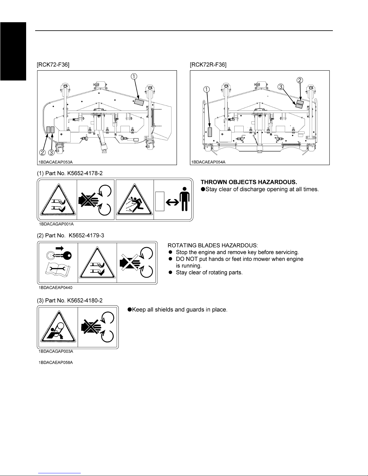
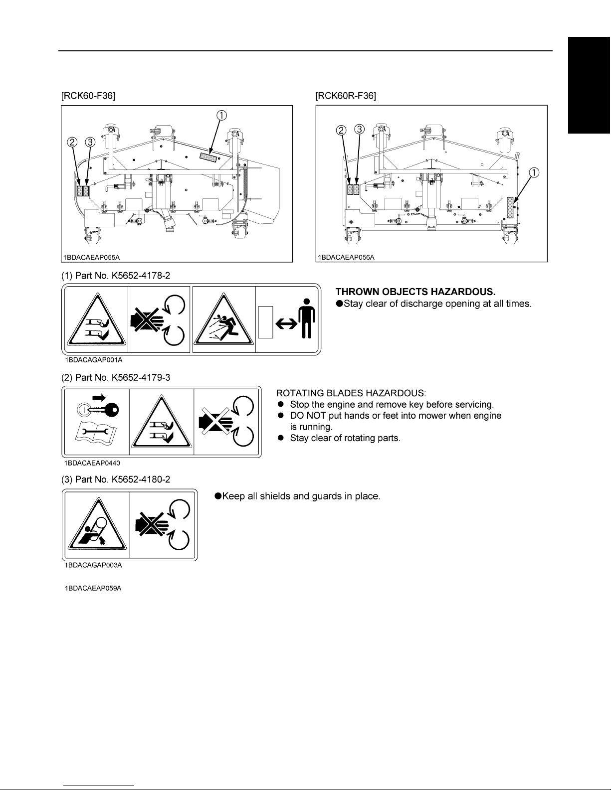
MOWER SAFETY LABELS
Page 8
3SAFE OPERATION
ENGLISH
Page 9

SAFE OPERATION4
ENGLISH
Page 10

5SAFE OPERATION
ENGLISH
1. Keep pictorial safety labels clean and free from obstructing material.
2. Clean pictorial safety labels with soap and water, dry with a soft cloth.
3. Replace damaged or missing pictorial safety labels with new labels from your local KUBOTA Dealer.
4. If a component with pictorial safety label(s) affixed is replaced with new part, make sure new label(s) is (are) attached
in the same location(s) as the replaced component.
5. Mount new pictorial safety labels by applying on a clean dry surface and pressing any bubbles to outside edge.
CARE OF PICTORIAL SAFETY LABELS
Page 11

Page 12
1IMPORTANT
ENGLISH
IMPORTANT
To obtain maximum productivity from your mower, the
following items should be read and observed.
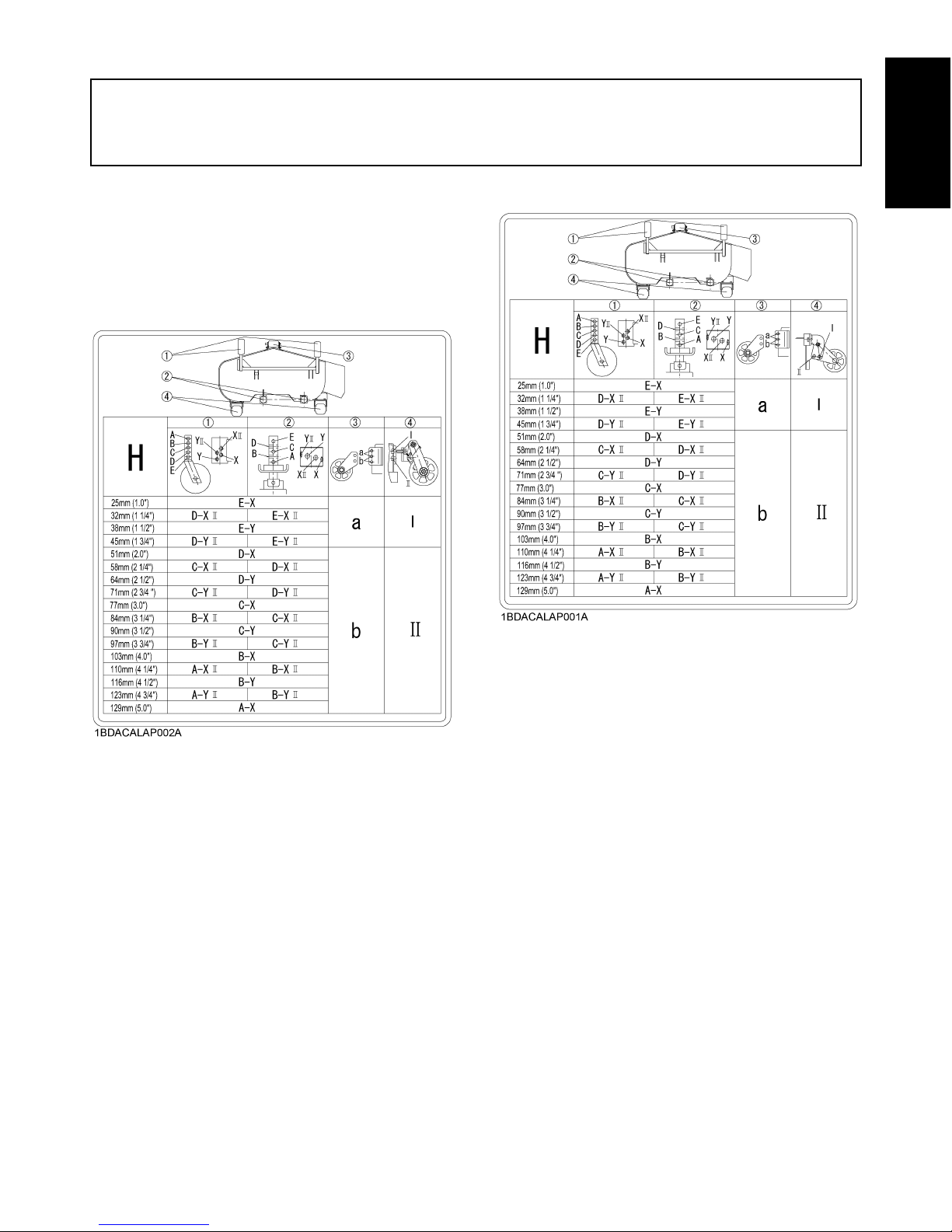
1. Adjust the anti-scalp rollers and wheels according to
the mowing height. Refer to the label below.
This label is also affixed to the mower deck.
[RCK72-F36 / RCK72R-F36]
[RCK60-F36 / RCK60R-F36]
(1) Front gauge wheel
(2) Lift rod
(3) Front roller
(4) Anti-scalp roller
(1) Front gauge wheel
(2) Lift rod
(3) Front roller
(4) Anti-scalp roller
Page 13

IMPORTANT2
ENGLISH
[RCK54-F28]
2. Grease the following parts. (See "MAINTENANCE
CHECK LIST" in "MAINTENANCE" section.)
A Universal joint
A Front gauge wheel brackets and front gauge
wheels
A Three spindle shafts
A Belt tension pivot and tension pulley
A Front roller
3. Remove the belt shield from the mower deck and
clean out debris daily.
4. When replacing the blades, follow the instructions as
shown below. (See "BLADE REPLACEMENT" in
"MAINTENANCE" section.)
(1) Front gauge wheel
(2) Lift rod
(3) Front roller
(1) Spindle holder
(2) Blade
(3) 2-Cup washers
(4) Spline boss
(5) Bolt
(6) Spindle guard
(1) Block (A) "Loosen" (counterclockwise)
Page 14

3SERVICE
ENGLISH
SERVICE
1. When in need of parts or service, give the serial
number of the mower to the dealer.
2. The serial number is located on the right side of the
deck.
3. For your reference, please record the serial number in
the space provided.
KUBOTA MOWER
MO DEL
SERI AL NUMBER
DATE OF PURCHASE
NA ME OF D EA LER
(1) Serial number
Page 15

4 INTRODUCTION
ENGLISH
INTRODUCTION
SPECIFICATIONS
Model RCK72-F36 RCK72R-F36 RCK60-F36 RCK60R-F36 RCK54-F28
Suitable front mower F2880, F3680 F2880
Mounting method 2 point linkage
Adjustment of cutting height Gauge wheel
Cutting width mm 1826 1524 1375
Cutting height mm 25 to 129
Discharge direction Side Rear Side Rear Side
Weight (Approx.) kg 214 210 180 170 130
Blade spindle speed r/s (rpm) 40.1 (2405) 44.9 (2695) 51.5 (3088)
Blade tip velocity m/s (fpm) 78.7 (15490) 73.8 (14520) 76.2 (15110)
Blade length mm 625 523 475
Number of blades 3
Dimensions
Total length mm 1160 1090 980
Total width mm 2250 1910 1850 1610 1770
Total height mm 450
Page 16

5INTRODUCTION
ENGLISH
MOWER TERMINOLOGY
[RCK72-F36]
[RCK72R-F36]
(1) Shield
(2) Gauge wheel arm right
(3) Gauge wheel arm left
(4) Discharge deflector
(5) Deck
(6) Gear box
(7) Front gauge wheel
(8) Universal joint
(9) Front roller
(10) Anti-scalp roller
(11) Center frame
(12) Blade
Page 17

6 INTRODUCTION
ENGLISH
[RCK60-F36]
[RCK60R-F36]
(1) Shield
(2) Gauge wheel arm right
(3) Gauge wheel arm left
(4) Discharge deflector
(5) Deck
(6) Gear box
(7) Front gauge wheel
(8) Universal joint
(9) Front roller
(10) Anti-scalp roller
(11) Center frame
(12) Blade
Page 18

7INTRODUCTION
ENGLISH
[RCK54-F28]
(1) Shield
(2) Gauge wheel arm right
(3) Gauge wheel arm left
(4) Discharge deflector
(5) Deck
(6) Gear box
(7) Front gauge wheel
(8) Universal joint
(9) Front roller
(10) Center frame
(11) Blade
Page 19

8 SETTING UP
ENGLISH
SETTING UP
Some of the mower parts were packed separately.
Read the following procedure to properly assemble
the mower.
PRE-ASSEMBLY
Take out all mower components from the case and check
the parts as shown in the figure.
[RCK72-F36]
[RCK72R-F36]
[RCK60-F36]
[RCK60R-F36]
[RCK54-F28]
Page 20

9SETTING UP
ENGLISH
SETTING UP THE MOWER
1. Attach the front gauge wheels to the arms of the deck
with the clevis pins and snap rings.
A Set the mark on top end of the front wheel shaft
forward.
A Check the tire inflation pressure.
[RCK72-F36 / RCK60-F36]
2. Install the discharge pin with the spring pushed
against the mower deck, then install the spring pin as
shown in the figure.
The spring should provide resistance to the discharge
deflector.
[RCK54-F28]
2. Install the discharge pin with the spring pushed against
the mower deck, then install the cotter pin as shown in
the figure.
The spring should provide resistance to the discharge
deflector.
(1) Clevis pin ø9x53, snap ring (ø45)
(2) Front gauge wheel
(3) Mark
(4) Front wheel shaft
(5) Gauge wheel arm
(A) "Forward"
Inflation Pressure 2.0 kgf/cm (28psi)
(1) Ground (A) "INSUFFICIENT"
(B) "NORMAL"
(C) "EXCESSIVE"
(1) Deck
(2) Spring
(3) Discharge pin
(4) Spring pin
(5) Discharge deflector
(A) "Front"
(1) Deck
(2) Spring
(3) Discharge pin
(4) Cotter pin
(5) Discharge deflector
(A) "Front"
Page 21

SETTING UP10
ENGLISH
[RCK72-F36 / RCK72R-F36]
3. Install the gas spring to the mower deck with the clevis
pin, the plain washer and the split pin.
(1) Gas spring
(2) Clevis pin, plain washer, split pin
Page 22

11MOWER MOUNTING
ENGLISH
MOWER MOUNTING
MOUNTING THE MOWER
To avoid personal injury:
A Before mounting the mower deck, read and
understand the use of the lift link lowering
speed control knob.
(See "Lift Link Lowering Speed Control Knob"
in "OPERATING THE MACHINE" section in the
operator's manual of the machine.)
A Place the PTO lever in the "DISENGAGE"
position.
A Place the High-Low gear shift lever in the
"NEUTRAL" position.
A The mower links (left hand, right hand) are
spring-loaded. Have an assistant hold the arm
in position when mounting the mower deck.
1. Move the mower deck under the mower links and
place the hydraulic lift lever in the "DOWN" position.
2. Attach the front end of the mower links to the mower
deck with clevis pins and set pins.
3. Start the engine, raise the mower deck, lock the lift link
lowering speed control knob and shut off the engine.
4. Install the lift rods to the mower deck with lock pins and
down the mower deck on the ground.
[RCK72-F36 / RCK72R-F36]
5. Attach the gas spring to the mower link with the clevis
pin and the rue ring cotter.
A When operating the mower, make sure the tilt lever is
unlocked.
A For tilting up the mower, see "MOWER TILT UP"
section in the operator's manual of the mower.
6. Pull back the coupler of the universal joint.
Push the universal joint onto the PTO shaft until the
coupler locks.
Slide the universal joint backward and forward to
check that the universal joint is locked securely.
A Finally pull the universal joint to see if it is locked tight
in position.
(1) Mower link
(2) Set pin
(3) Clevis pin
(1) Lift rod
(2) Lock pin
(3) Mower link
(4) Gas spring
(5) Tilt lever ("UNLOCKED" position)
(6) Rue ring cotter
(1) Universal joint
(2) Coupler
(3) Chain
(A) "PULL"
Page 23

MOWER MOUNTING12
ENGLISH
7. [Only for universal joint with the chain]
Hook the chain on the cover stay of the frame.
8. After mounting the mower deck, adjust the lift link
lowering speed.
DISMOUNTING THE MOWER DECK
For dismounting the mower deck, reverse the above
procedures.
To avoid personal injury:
A The mower links (left hand, right hand) are
spring-loaded. Have an assistant hold the arm
in position when mounting the mower deck.
(1) Universal joint
(2) Chain
(3) Cover stay
Page 24

13OPERATING THE MOWER
ENGLISH
OPERATING THE MOWER
MAKING THE MOST OF YOUR MOWER
1. When using your mower for the first time, choose a
smooth level area and cut in straight and slightly
overlapping strips.
2. The size and type of the area to be mowed will
determine the proper mowing pattern. Take into
account obstructions, such as trees, fences and
buildings. To keep grass clippings off fences,
sidewalks, etc., it is advisable to go over the outside of
the area to be mowed several times in a clockwise
direction. To mow the area remaining, work in a
counterclockwise direction so the clippings are
dispersed onto the previously cut area. (For side
discharge mower)
3. Always keep the left side of the mower toward trees,
posts or other obstacles on the first trip around the
obstacle. (For side discharge mower)
4. Most lawns should be mowed to keep the grass
approximately 50 to 80mm (2 to 3 in.) high. Best
results are obtained by cutting often and not too short.
To keep a green lawn, never mow more than one third
of the height of the grass or a maximum of 25mm (1
in.) in one mowing.
For extremely tall grass, set the cutting height at
maximum for the first mowing, then reset to the
desired height and mow again. Allow the grass to grow
to 80mm (3 in.), then cut off only the top growth.
5. On thick or springy grass or soft ground, the mower
rollers may sink into the ground, resulting in the cut
being too low.
Adjust the cutting height to get the desired height of
cut.
6. For best appearance, grass should be cut in the
afternoon or evening when it is free of moisture.
CUTTING HEIGHT
To avoid serious injury or death:
A Never operate the mower in transport position.
1. Check the both front gauge wheel pressures daily and
inflate as necessary to prevent uneven cutting height.
(See "FRONT GAUGE WHEEL" in "MAINTENANCE"
section.)
2. Cutting height can be adjusted from 25 to 129 mm (1.0
to 5 in.). To set the cutting height, adjust the front
gauge wheels and lift rods.
3. Adjust the anti-scalp roller as shown in the figure.
[RCK72-F36 / RCK72R-F36]
(1) Front gauge wheel
(2) Lift rod
(3) Front roller
(4) Anti-scalp roller
Page 25

OPERATING THE MOWER14
ENGLISH
[RCK60-F36 / RCK60R-F36]
[RCK54-F28]
C For adjusting the lift rod tension
To adjust the tension, insert the set pin from A, B, C or D
as shown in the figure.
A For easy adjusting of the lift rods, place a wooden
block under the rear end of the mower deck before
lowering the mower deck.
A Cutting height will change because of the ground
condition.
4. Use higher settings for mowing in a rough area or
when mowing high grass. Lower settings should be
used only for smooth lawns where short grass is
desired.
5. Lower the mower deck by pushing the hydraulic
control lever forward. This lowers the mower deck
from the transport position to the operating position.
(1) Front gauge wheel
(2) Lift rod
(3) Front roller
(4) Anti-scalp roller
(1) Front gauge wheel
(2) Lift rod
(3) Front roller
Page 26

15OPERATING THE MOWER
ENGLISH
OPERATING MOWER
To avoid serious injury or death:
A Do not operate the mower without the
discharge deflector properly in place.
To avoid personal injury:
A Clear the work area of objects which might be
picked up and thrown.
A Do not direct the opening of the deflector at
bystanders or animals. Ejected objects may
cause injury. Plan your mowing carefully
before starting operations.
A Keep bystanders and animals away from the
mowing area.
A Be sure to disengage the front PTO clutch of
the mower before starting the engine.
1. Keep the engine running at full throttle for best results.
Control travel speed by the speed control pedal or
lever.
2. During heavy duty use, operate the machine at a
slower ground speed or go over the area twice.
3. Keep the mower deck in the fully raised position when
the mower is disengaged.
4. The mower will not cut cleanly if the ground speed is
too high or if the blade speed drops due to an
overload.
A To prevent the engine from overheating, keep the
radiator and the radiator net clean.
Page 27

16 MAINTENANCE
ENGLISH
MAINTENANCE
MAINTENANCE CHECK LIST
To avoid personal injury:
A Stop the engine and remove the key.
A The jobs indicated by must be done initially.
No. Check Point
Used hours (Change or check every interval)
Reference
page
Daily 50 Hrs 150 Hrs 2 years
1 Oil leakage check 17
2 Make sure blade caps crews are tight. 21
3 Blade wear check 21
4 All hardware check ---
5 Make sure all pins are in place. ---
6 Mower deck cleaning ---
7
Greasing
A Universal joint
A Spindle shafts
A Belt tension pulley
A Belt tension pivot
17
A Front gauge wheels and gauge wheel
brackets
A Front roller
17
8 Gear box oil check 17
9 Gear box oil change 17
10 Gear box oil seal change ---
11 Front gauge wheel pressure 23
Page 28

17MAINTENANCE
ENGLISH
CHECK AND MAINTENANCE
To avoid personal injury:
A Stop the engine, set the parking brake, and
remove the key.
BGear box oil
1. To check the oil level, remove the check plug (bolt).
A Place the mower on a level surface.
Loosen the check plug. Oil should be visible
through the opening. If the oil level is too low, add
new oil to the check plug level.
(Use SAE 90 gear oil)
0.4 L (0.42 qts.)
A Do not fill oil over the level to reach the check plug.
BLubricating All Grease Fittings
(Use multipurpose EP2 grease (NLGI Grade No. 2).)
Grease the following locations.
(1) Drain plug (Bolt)
(2) Check plug (Bolt)
(3) Inlet (Bolt)
(1) Mower universal joint
(2) Grease nipple
(A) Apply grease to the spline with
the brush.
(1) Universal joint
(1) Front gauge wheel bracket
(2) Front gauge wheel
Page 29

MAINTENANCE18
ENGLISH
[RCK72-F36 / RCK72R-F36 / RCK60-F36 /
RCK60R-F36]
[RCK54-F28]
MOWER TILP UP
To avoid personal injury or death:
A Do not start the engine while tilting the mower
deck.
To avoid personal injury:
A Be sure to tilt the mower on a level surface and
the parking brake on.
A Move the PTO lever in the "DISENGAGE"
position.
A Move the High-Low gear shift lever in the
"NEUTRAL" position.
BHow to Tilt Up
1. Place the PTO lever in the "DISENGAGE" position.
2. Stop the engine, set the parking brake and remove the
key.
3. Place the High-Low gear shift lever in the "NEUTRAL"
position.
4. [Only for universal joint with the chain]
Remove the chain from the frame.
5. Remove the universal joint from the machine.
(1) Front roller
(1) Spindle shaft
(2) Belt tension pivot
(3) Belt tension pulley
(4) Center spindle shaft
(1) Spindle shaft
(2) Belt tension pivot
(3) Belt tension pulley
(4) Center spindle shaft
(1) Coupler
(2) Universal joint
(3) Chain
Page 30

19MAINTENANCE
ENGLISH
[RCK72-F36 / RCK72R-F36]
For assisting the tilting up force.
A Detach the tilt pipe set in the mower deck, and set it in
the tilt lever.
A Pull the tilt pipe in the direction of the arrow, hook the
tilt lever, and remove the tilt pipe.
To avoid personal injury:
A Securely insert the tilt lever in the tilt pipe.
A Never separate the hand from the tilt pipe until
the tilt lever is locked to the hook securely.
Since the tilt lever is a spring loaded lever, the
pipe may bounce back.
6. Start the engine and raise the mower fully.
7. Lock the lift link lowering speed.
(For detailed procedure, refer to the machine
"OPERATOR'S MANUAL".)
8. Stop the engine and remove the key.
9. Pull out the lock pins (LH, RH) of the anti-scalp roller
and push them upward.
10.Pull out the lock pins (LH, RH) of the rear lift rod and
lock them in the open position.
11.Disengage the lock of the tilting pin, and pull up the
mower deck as shown in the figure.
(1) Tilt lever
(2) Tilt pipe
(3) Hook
(A) "UNLOCKED"
(B) "LOCKED"
(1) Anti-scalp roller
(2) Lock pin
(A) "Upward"
(1) Mower link
(2) Lift rod
(3) Lock pin
(1) Tilting pin
Page 31

MAINTENANCE20
ENGLISH
To avoid personal injury:
A Make sure the tilting pin is locked to the mower
link securely.
12.Lock the tilting pin to the mower link as shown in the
figure.
BHow to Mount the Mower
1. To mount the mower to the machine, reverse the
above procedures.
To avoid personal injury:
A Be sure to tilt the mower on a level surface and
the parking brake on.
A Move the PTO lever in the "DISENGAGE"
position.
A Move the High-Low gear shift lever in the
"NEUTRAL" position.
[RCK72-F36, RCK72R-F36]
After mounting the mower:
2. Set the tilt lever to the "UNLOCKED" position with the
tilt pipe.
3. Adjust the lift link lowering speed.
(For detailed procedure, refer to the operator's manual
of the machine.)
(1) Mower link
(2) Tilting pin
Page 32

21MAINTENANCE
ENGLISH
BLADE REPLACEMENT
To avoid personal injury:
A Wear heavy gloves or wrap the end of the blade
with a rag when you handle blades.
A The blade bolts have Right hand threads. Turn them
counterclockwise to loosen.
A To prolong the service life of the blades, reposition
them as shown in the figure below periodically.
The blade cutting edges should be kept sharp at all times.
Sharpen the cutting edges, if they resemble the blade in
figure (B). Replace the blades if they appear similar to the
blade as shown in figure (C).
BHow to Check and Remove Blades
1. Tilt up the mower and turn it over to expose the blades.
2. Wedge a block of wood between the blade and mower
housing or install box wrench over pulley nut to
prevent spindle from rotating while removing blade
bolts, loosen the blade bolt as shown in the figure.
A Use the proper metric size box or socket wrench to
tighten or loosen the blade mounting bolt.
A Make sure that the cup washer is not flattened out or
worn, causing blade to slip easily. Replace both cup
washers if either of them is damaged.
Pass the spline boss through the blade and 2 cup
washers, and tighten the bolt.
A Tightening torque of the blade bolts.
(1) LH blade
(2) Center blade
(3) RH blade
(A) New blade
(B) Worn blade
(C) Cracked blade
(1) Block (A) "Loosen"
(1) Spindle holder
(2) Blade
(3) 2-Cup washers
(4) Spline boss
(5) Bolt
(6) Spindle guard
Blade 10 to 12 kgf-m (72 to 87 ft-lbs.)
Page 33

MAINTENANCE22
ENGLISH
BHow to Sharpen Blades
1. To sharpen the blades, clamp the blade securely in a
vise.
Use a large mill file and file along the original bevel
until sharp.
2. To check the blade for balance, place a small rod
through the center hole. The blade should balance on
this rod. If the blade is not balanced, file the heavy side
of the blade until balance is achieved.
BELT REPLACEMENT
1. Remove the mower from the machine.
2. Remove the left and right hand shields from the mower
deck. Also only for RCK54-F28 remove the center
shield.
3. Clean around the gear box.
4. Remove the belt from the tension pulley.
5. Remove the right hand bracket which mounts the gear
box to the mower deck.
Slip the belt over the top of the gear box.
6. To install a new belt, reverse the above steps.
IMPORTANT:
To avoid the misalignment of the center spindle.
A Before attaching the bolt, attach the right hand bracket
securely.
A Tighten bracket bolts securely.
(1) Tension pulley
(2) Belt
(3) Bracket (RH)
(4) Tension spring
Page 34

23MAINTENANCE
ENGLISH
FRONT GAUGE WHEEL [TIRES]
To avoid personal injury or death:
A Never exceed the tire pressure shown below
(maximum limit) when attempting to seat a
bead. If beads have not been seated by the time
the pressure reaches maximum limit, deflate
the assembly, reposition the tire on the rim,
lubricate, and reinflate. After seating the bead,
adjust inflation pressure as recommended in
the inflation pressure chart.
To avoid personal injury:
A Do not attempt to mount a tire unless qualified.
Use proper equipment.
The tire pressure is factory-set to the correct level,
however, tire pressure will drop slowly in the course of
time. Check tire pressure daily and inflate it as necessary.
A When replacing the gauge wheel, check the inflation
pressure of the tires.
ADJUSTING THE LIFT RODS
To avoid personal injury:
A Shut off the engine, set the parking brake, and
remove the key.
1. Park the front mower and the mower deck on a level
ground and set the desired cutting height.
2. Check whether the mower deck is level.
3. If not, adjust the level by the spacers.
Reference
Max inflation pressure
3.5 x 10 Pa
(50 psi, 3.5 kgf/cm )
Recommend pressure
2.0 x 10 Pa
(29 psi, 2.0 kgf/cm )
(1) Spacers
(2) Mower link
Tire
Number of spacer
RCK72-F36
RCK72R-F36
RCK60-F36
RCK60R-F36
RCK54-F28
24" 3 3 3
Page 35

MAINTENANCE24
ENGLISH
ADJUSTING LIFT SPRINGS (LH & RH)
In order to help improve traction, adjust the lift springs
according to the chart below.
RCK72-F36, RCK72R-F36,
RCK60-F36, RCK60R-F36,
RCK54-F28
RH L = 50 mm (2.0 in.)
LH L = 70 mm (2.8 in.)
(L) RIGHT HAND: 50mm (2.0 in.)
LEFT HAND: 70mm (2.8 in.)
Page 36

25MAINTENANCE
ENGLISH
TIGHTENING TORQUE CHART
A Figure "7" on the top of the bolt indicates that the bolt is of special material.
A Before tightening, check the figure on the top of bolt.
Thread
Size
d (mm)
Hexa-Bolt
Head size
B (mm)
No mark 7T
ft-lbs N-m kgf-m ft-lbs N-m kgf-m
M8 12 or 13
13.0 to 15.2
(14.1 1.1)
17.8 to 20.6
(19.2 1.4)
1.9 to 2.1
(2.0 0.1)
17.5 to 20.3
(18.9 1.4)
23.5 to 27.5
(25.5 2.0)
2.4 to 2.8
(2.6 0.2)
M10 14 or 17
28.9 to 33.3
(31.1 2.2)
39.3 to 45.1
(42.2 2.9)
4.0 to 4.6
(4.3 0.3)
35.4 to 41.2
(38.3 2.9)
48.1 to 55.9
(52.0 3.9)
4.9 to 5.7
(5.3 0.4)
M12 17 or 19
46.3 to 53.5
(49.9 3.6)
62.8 to 72.6
(67.7 4.9)
6.4 to 7.4
(6.9 0.5)
57.1 to 66.5
(61.8 4.7)
77.6 to 90.2
(83.9 6.3)
8.0 to 9.2
(8.6 0.6)
M14 19 or 22
79.6 to 92.6
(86.1 6.5)
107.9 to 125.5
(116.7 8.8)
11.0 to 12.8
(11.9 0.9)
91.1 to 108.5
(99.8 8.7)
123.6 to 147.0
(135.3 11.7)
12.6 to 15.0
(13.8 1.2)
American standard cap screws
with UNC or UNF threads
Metric cap screws
SAE grade No.
GR.5 GR.8
Property class
class 8.8 class 10.9
5/16
(ft-lbs)
(N-m)
(kgf-m)
17 to 20.5
23.1 to 27.8
2.35 to 2.83
24 to 29
32.5 to 39.3
3.31 to 4.01
M8
(ft-lbs)
(N-m)
(kgf-m)
17.4 to 20.2
23.6 to 27.4
2.4 to 2.8
21.7 to 25.3
29.4 to 34.3
3.0 to 3.5
3/8
(ft-lbs)
(N-m)
(kgf-m)
35 to 42
47.5 to 57.0
4.84 to 5.81
45 to 54
61.0 to 73.2
6.22 to 7.46
M10
(ft-lbs)
(N-m)
(kgf-m)
35.5 to 41.2
48.1 to 55.8
4.9 to 5.7
44.9 to 52.1
60.8 to 70.5
6.2 to 7.2
1/2
(ft-lbs)
(N-m)
(kgf-m)
80 to 96
108.5 to 130.2
11.06 to 13.28
110 to 132
149.2 to 179.0
15.21 to 18.25
M12
(ft-lbs)
(N-m)
(kgf-m)
57.2 to 66.5
77.5 to 90.1
7.9 to 9.2
76.0 to 86.8
103 to 117
10.5 to 12.0
9/16
(ft-lbs)
(N-m)
(kgf-m)
110 to 132
149.2 to 179.0
15.21 to 18.25
160 to 192
217.0 to 260.4
22.13 to 26.55
M14
(ft-lbs)
(N-m)
(kgf-m)
91.5 to 108.4
124 to 147
12.6 to 15.0
123 to 144
167 to 196
17.0 to 20.0
5/8
(ft-lbs)
(N-m)
(kgf-m)
150 to 180
203.4 to 244.1
20.74 to 24.89
220 to 264
298.3 to 358.0
30.42 to 36.51
M16
(ft-lbs)
(N-m)
(kgf-m)
145 to 166
196 to 225
20.0 to 23.0
192 to 224
260 to 303
26.5 to 31.0
Page 37

26 TROUBLESHOOTING
ENGLISH
TROUBLESHOOTING
Any service item refer to operator's manual for proper maintenance procedure.
Trouble Cause Remedy
Discharge cover plugged. A Grass to wet
A Grass too long.
A Cutting too low.
A Engine rpm too low.
A Ground speed too fast.
A Wait for grass to dry.
A Raise cutting height and cut grass twice.
A Raise cutting height.
A Mow at full throttle.
A Slow down.
Streaking of uncut grass. A Ground speed too fast.
A Engine rpm too low.
A Grass too long.
A Blades dull or damaged.
A Debris in mower deck.
A Slow down.
A Mow at full throttle, check and reset engine
rpm.
A Cut grass twice.
A Replace blades or have blades sharpened.
A Clean mower deck.
Uneven cut. A Mower deck not level.
A Ground speed too fast.
A Blades dull.
A Blades worn.
A Low tire inflation.
A Gauge wheels not adjusted correctly.
A Level mower deck.
A Slow-down.
A Have blades sharpened.
A Replace blades.
A Add air to correct.
A Adjust gauge wheels.
Blades scalping grass. A Cutting height too low.
A Turning speed too fast.
A Ridges in terrain.
A Rough or uneven terrain.
A Gauge wheels not adjusted correctly.
A Bent blade(s).
A Raise cutting height.
A Reduce speed on turns.
A Change mowing pattern.
A Adjust gauge wheels and antiscalp rollers.
A Adjust gauge wheels and antiscalp rollers.
A Replace blade(s).
Belt slipping. A Mower deck plugged.
A Debris in pulleys.
A Worn belt.
A Unplug and clean mower deck.
A Clean pulleys.
A Replace belt.
Excessive vibration. A Debris on mower deck or in pulleys.
A Damaged drive belt.
A Damaged pulleys.
A Pulleys out of alignment.
A Blades out of balance.
A Clean mower deck and pulleys.
A Replace drive belt.
A Replace pulleys.
A See your KUBOTA Dealer.
A Have blades balanced.
Mower loads down
machine.
A Engine rpm too low.
A Ground speed too fast.
A Debris wrapped around mower
spindles.
A Mow at full throttle, check and reset engine
rpm.
A Slow down.
A Clean mower.
 Loading...