

Page 1

WORKSHOP MANUAL
KiSC issued 03, 2017 A
TRACTOR,FRONT LOADER,
BACKHOE,ROTARY MOWER
BX23S,LA340,BT603,
RCK54D,RCK60D,
RCK54,RCK60B
Page 2

TO THE READER
KiSC issued 03, 2017 A
This Workshop Manual tells the servicing personnel about the mechanism, servicing and maintenance of BX23S.
contains 4 parts: "Information", "General", "Mechanism", and "Servicing".
Information
This section primarily contains information below.
• Safety first
• Safety decal
• Specifications
• Dimensions
General
This section primarily contains information below.
• Engine identification
• Model identification
•
General precautions
• Maintenance check list
• Check and maintenance
• Special tools
Mechanism
This section contains information on the structure and the function of the unit. Before you continue with the
subsequent sections, make sure that you read this section.
Servicing
This section primarily contains information below.
• Troubleshooting
• Servicing specifications
• Tightening torques
• Checking, disassembling and servicing
All illustrations, photographs and specifications contained in this manual are of the newest information available at the
time of publication.
Kubota reserves the right to change all information at any time without notice.
Since this manual includes many models, information or illustrations and photographs can show more than one
model.
It
© KUBOTA Corporation
March, 2017
Page 3

CONTENTS
BX23S, LA340, BT603, RCK54D, RCK60D, RCK54, RCK60B
i
KiSC issued 03, 2017 A
1. INFORMATION
SAFETY FIRST
1. Safety first................................................................................................................................................. 1-1
2. Before you start service............................................................................................................................1-2
3. Start safely................................................................................................................................................ 1-2
4. Operate safely ..........................................................................................................................................1-2
5. Protect against high pressure spray .........................................................................................................1-3
6. Avoid hot exhaust .....................................................................................................................................1-3
7. Exhaust filter cleaning
8. Prevent a fire ............................................................................................................................................1-4
9. Keep a good airflow in the work area .......................................................................................................1-4
10. Discard fluids correctly ...........................................................................................................................1-4
11. Prevent acid burns .................................................................................................................................. 1-4
12. Prepare for emergencies ........................................................................................................................1-5
SAFETY LABEL.................................................................................................................................................1-7
1. Safety labels for BX tractor.......................................................................................................................1-7
2. Safety labels for mower ..........................................................................................................................1-12
3. Safety labels for loader...........................................................................................................................1-13
4. Safety labels for backhoe .......................................................................................................................1-15
SPECIFICATIONS ...........................................................................................................................................1-17
1. BX tractor specifications .........................................................................................................................1-17
2. Mower specifications ..............................................................................................................................1-19
3. Loader specifications..............................................................................................................................1-20
3.1 Loader specifications ......................................................................................................................1-20
3.2 Bucket specifications....................................................................................................................... 1-21
3.3 Dimensional specifications of loader............................................................................................... 1-22
3.4 Operational specifications of loader ................................................................................................1-23
4. Backhoe specifications ...........................................................................................................................1-25
4.1 Backhoe specifications.................................................................................................................... 1-25
4.2 Backhoe dimensions .......................................................................................................................1-26
4.3 Backhoe lift capacity .......................................................................................................................1-27
TRAVELING SPEEDS .....................................................................................................................................1-29
DIMENSIONS ..................................................................................................................................................1-31
..................................................................................................................................................1-1
..............................................................................................................................1-3
2. GENERAL
IDENTIFICATION...............................................................................................................................................2-1
1. Tractor identification .................................................................................................................................2-1
1.1 Checking serial number and hour meter ...........................................................................................2-1
1.2 Cylinder number................................................................................................................................2-1
2. Checking mower identification..................................................................................................................2-2
3. Checking loader identification................................................................................................................... 2-2
4. Checking backhoe identification ...............................................................................................................2-2
GENERAL PRECAUTIONS...............................................................................................................................2-3
HANDLING PRECAUTIONS FOR ELECTRICAL PARTS AND WIRING .......................................................... 2-5
LUBRICANTS, FUEL AND COOLANT ..............................................................................................................2-7
1. BX tractor.................................................................................................................................................. 2-7
1.1 Lubricants, fuel, and coolant .............................................................................................................2-7
1.1.1 Fuel...........................................................................................................................................2-8
1.1.2 Engine oil ..................................................................................................................................2-8
1.1.3 Transmission oil........................................................................................................................ 2-8
1.2 Overview of biodiesel fuel (BDF)....................................................................................................... 2-9
2. Mower..................................................................................................................................................... 2-11
2.1 Lubricants........................................................................................................................................ 2-11
TIGHTENING TORQUES ................................................................................................................................2-13
Page 4

1. General use screws, bolts and nuts .......................................................................................................2-13
ii
BX23S, LA340, BT603, RCK54D, RCK60D, RCK54, RCK60B
KiSC issued 03, 2017 A
2. Stud bolts
3. Metric screws, bolts and nuts
................................................................................................................................................2-13
.................................................................................................................2-14
4. American standard screws, bolts and nuts with UNC or UNF threads ...................................................
5. Plugs
6. Adapters, elbows and others
MAINTENANCE CHECK LIST
.......................................................................................................................................................2-14
..................................................................................................................2-15
.........................................................................................................................2-17
1. BX tractor service intervals.....................................................................................................................2-17
2. Mower service intervals
CHECK AND MAINTENANCE
..........................................................................................................................2-19
.........................................................................................................................2-21
1. Periodic service ......................................................................................................................................2-21
1.1 Opening bonnet............................................................................................................................... 2-21
1.2 Daily check......................................................................................................................................2-21
1.2.1 Walk around inspection...........................................................................................................2-21
1.2.2 Checking fuel gauge and refueling .........................................................................................2-21
1.2.3 Checking engine oil level ........................................................................................................2-22
1.2.4 Checking transmission fluid level............................................................................................ 2-22
1.2.5 Checking coolant level............................................................................................................2-23
1.2.6 Cleaning panel and radiator screen........................................................................................ 2-23
1.2.7 Checking brake pedal .............................................................................................................2-24
1.2.8 Checking gauges, meters, and Easy Checker™.....................................................................2-24
1.2.9 Checking head light, hazard light, and tail light ......................................................................2-24
1.2.10 Checking seat belt and ROPS ..............................................................................................2-24
1.2.11 Checking and cleaning electrical wiring and battery cables..................................................2-24
1.2.12 Checking movable parts .......................................................................................................2-25
1.3 Check points of initial 50 hours .......................................................................................................2-25
1.3.1 Changing engine oil ................................................................................................................2-25
1.3.2 Replacing engine oil filter........................................................................................................ 2-25
1.3.3 Replacing transmission oil filter ..............................................................................................2-26
1.3.4 Changing transmission fluid.................................................................................................... 2-26
1.3.5 Cleaning transmission strainer ...............................................................................................2-27
1.4 Check points of every 50 hours....................................................................................................... 2-27
1.4.1 Greasing .................................................................................................................................2-27
1.4.2 Checking engine start system................................................................................................. 2-29
1.4.3 Checking operator presence control (OPC) system ...............................................................2-29
1.4.4 Checking wheel bolt torque ....................................................................................................2-30
1.4.5 Cleaning lock lever shaft......................................................................................................... 2-30
1.5 Check points of every 100 hours..................................................................................................... 2-30
1.5.1 Checking battery condition .....................................................................................................2-30
1.5.2 Cleaning air cleaner element ..................................................................................................2-32
1.5.3 Checking fuel filter ..................................................................................................................2-32
1.5.4 Adjusting fan belt tension........................................................................................................ 2-33
1.5.5 Adjusting HST neutral spring ..................................................................................................2-33
1.5.6 Adjusting brake pedal .............................................................................................................2-34
1.6 Check point of every 200 hours ......................................................................................................2-34
1.6.1 Replacing engine oil filter........................................................................................................ 2-34
1.6.2 Changing engine oil ................................................................................................................2-35
1.6.3 Replacing transmission oil filter ..............................................................................................2-35
1.6.4 Adjusting toe-in .......................................................................................................................2-36
1.7 Check points of every 400 hours..................................................................................................... 2-36
1.7.1 Adjusting front axle pivot......................................................................................................... 2-36
1.7.2 Changing transmission fluid.................................................................................................... 2-37
1.7.3 Cleaning transmission strainer ...............................................................................................2-38
1.7.4 Changing front axle case oil ...................................................................................................2-38
1.7.5 Replacing fuel filter element ...................................................................................................2-38
1.8 Check points of every 800 hours..................................................................................................... 2-39
1.8.1 Adjusting engine valve clearance ...........................................................................................2-39
1.9 Check points of every 1000 hours or 1 year ...................................................................................2-39
2-14
Page 5

1.9.1 Replacing air cleaner element ................................................................................................2-39
BX23S, LA340, BT603, RCK54D, RCK60D, RCK54, RCK60B
iii
KiSC issued 03, 2017 A
1.10 Check points of every 1500 hours
1.10.1 Checking injection pressure of fuel injection nozzle
1 Check points of every 2000 hours or 2 years
1.1
1.1 Flushing cooling system and changing coolant..................................................................... 2-39
1.1
1.1
1.2 Antifreeze
..............................................................................................................................2-40
.................................................................................................2-39
.............................................................
2-39
................................................................................2-39
1.12 Check points of every 3000 hours................................................................................................. 2-41
1.12.1 Checking injection pump....................................................................................................... 2-41
1.13 Check points of every 1 year......................................................................................................... 2-41
1.13.1 Checking intake air line......................................................................................................... 2-41
1.13.2 Checking radiator hoses and hose clamps........................................................................... 2-41
1.13.3 Checking power steering line................................................................................................ 2-41
1.13.4 Checking fuel lines................................................................................................................ 2-42
1.13.5 Checking engine breather hose............................................................................................2-42
1.14 Check points of every 4 years.......................................................................................................2-43
1.14.1 Replacing radiator hose........................................................................................................2-43
1.14.2 Replacing fuel hose ..............................................................................................................2-43
1.14.3 Replacing power steering hose ............................................................................................2-43
1.14.4 Replacing intake air line........................................................................................................ 2-43
1.14.5 Replacing engine breather hose...........................................................................................2-43
1.15 Service as required .......................................................................................................................2-43
1.15.1 Bleeding fuel system............................................................................................................. 2-43
1.15.2 Replacing fuse ......................................................................................................................2-43
1.15.3 Replacing light bulb ..............................................................................................................2-44
2. Mower.....................................................................................................................................................2-44
2.1 Check points of daily or each use ...................................................................................................2-44
2.1.1 Retightening mower blade screw............................................................................................ 2-44
2.1.2 Checking mower blade ...........................................................................................................2-45
2.1.3 Checking mower belt ..............................................................................................................2-45
2.1.4 Checking gear box oil level..................................................................................................... 2-45
2.1.5 Greasing spindle shafts, belt tension pivot and tension pulley ...............................................2-46
2.1.6 Greasing front and rear anti-scalp rollers ...............................................................................2-46
2.1.7 Greasing universal joint ..........................................................................................................2-46
2.2 Check points of initial 50 hours .......................................................................................................2-47
2.2.1 Changing gear box oil.............................................................................................................2-47
2.3 Check point of every 150 hours ......................................................................................................2-47
2.3.1 Changing gear box oil.............................................................................................................2-47
2.4 Check points of every 1 year........................................................................................................... 2-47
2.4.1 Checking gear box oil seal...................................................................................................... 2-47
2.5 Check point of every 4 years........................................................................................................... 2-48
2.5.1 Replacing gear box oil seal..................................................................................................... 2-48
3. Front loader ............................................................................................................................................2-48
3.1 Check points of daily or each use ...................................................................................................2-48
3.1.1 Checking transmission fluid level............................................................................................ 2-48
3.1.2 Checking hydraulic hoses....................................................................................................... 2-48
3.2 Check points of every 10 hours....................................................................................................... 2-49
3.2.1 Greasing loader ......................................................................................................................2-49
3.3 Check points of every 50 hours....................................................................................................... 2-49
3.3.1 Checking torque of main frame bolt and nut........................................................................... 2-49
4. Backhoe.................................................................................................................................................. 2-49
4.1 Check points of daily or each use ...................................................................................................2-49
4.1.1 Checking transmission fluid level............................................................................................ 2-49
4.1.2 Checking hydraulic hoses....................................................................................................... 2-49
4.1.3 Checking backhoe mounting pin............................................................................................. 2-50
4.2 Check points of every 10 hours....................................................................................................... 2-50
4.2.1 Greasing backhoe................................................................................................................... 2-50
4.3 Check points of every 50 hours....................................................................................................... 2-51
4.3.1 Checking torque sub frame bolt and nut................................................................................. 2-51
Page 6

TIRES, WHEELS, AND BALLAST...................................................................................................................2-53
iv
BX23S, LA340, BT603, RCK54D, RCK60D, RCK54, RCK60B
KiSC issued 03, 2017 A
1. T
2. Wheel tread
........................................................................................................................................................2-53
ires
1.1 Inflation pressure of tires
1.2 Dual tires
.........................................................................................................................................2-53
.................................................................................................................2-53
............................................................................................................................................2-53
2.1 Front wheels
....................................................................................................................................2-54
2.2 Rear wheels ....................................................................................................................................2-54
3. Ballast
.....................................................................................................................................................2-55
3.1 Front ballast
....................................................................................................................................2-55
3.2 Rear ballast .....................................................................................................................................2-55
IMPLEMENT LIMITATIONS ............................................................................................................................. 2-57
1. Implement limitation tables .....................................................................................................................2-57
SPECIAL TOOLS............................................................................................................................................. 2-61
1. Special tools for engine ..........................................................................................................................2-61
1.1 Special use puller set ......................................................................................................................2-61
1.2 Diesel engine compression tester (for injection nozzle).................................................................. 2-61
1.3 Nozzle tester ...................................................................................................................................2-61
1.4 Injection pump pressure tester........................................................................................................2-61
1.5 Valve guide replacing tool ...............................................................................................................2-62
1.6 Bushing replacing tool.....................................................................................................................2-63
1.7 Flywheel stopper .............................................................................................................................2-64
1.8 Crankshaft bearing 1 replacing tool ................................................................................................2-64
2. Special tools for tractor...........................................................................................................................2-65
2.1 Tie-rod end lifter ..............................................................................................................................2-65
2.2 Independent PTO clutch spring compression tool...........................................................................2-65
2.3 Disassembling and assembling stand (1/2) ....................................................................................2-66
2.4 Disassembling and assembling stand (2/2) ....................................................................................2-68
2.5 Check and high pressure relief valve assembly tool .......................................................................2-70
3. ENGINE
MECHANISM .....................................................................................................................................................3-1
1. Engine body.............................................................................................................................................. 3-1
1.1 Function of cylinder block.................................................................................................................. 3-1
1.2 Function of closed breather............................................................................................................... 3-1
1.3 Function of half-floating head cover ..................................................................................................3-1
1.4 Function of piston..............................................................................................................................3-2
1.5 Function of piston ring.......................................................................................................................3-2
1.6 Function of connecting rod................................................................................................................3-2
1.7 Function of crankshaft.......................................................................................................................3-2
1.8 Function of camshaft.........................................................................................................................3-3
1.9 Function of rocker arm ......................................................................................................................3-3
1.10 Function of flywheel ........................................................................................................................3-3
1.11 Function of timing gears ..................................................................................................................3-4
2. Lubricating system.................................................................................................................................... 3-5
2.1 Overview of lubricating system .........................................................................................................3-5
2.2 Function of oil strainer.......................................................................................................................3-7
2.3 Function of oil pump..........................................................................................................................3-7
2.4 Function of oil filter ............................................................................................................................3-7
2.5 Function of relief valve ......................................................................................................................3-8
2.6 Function of oil pressure switch..........................................................................................................3-8
3. Cooling system .........................................................................................................................................3-9
3.1 Overview of cooling system ..............................................................................................................3-9
3.2 Function of water pump................................................................................................................... 3-11
3.3 Function of radiator .........................................................................................................................3-11
3.4 Function of radiator cap .................................................................................................................. 3-11
4. Fuel system ............................................................................................................................................3-12
4.1 Overview of fuel system ..................................................................................................................3-12
4.2 Function of fuel filter........................................................................................................................3-12
Page 7

4.3 Function of fuel feed pump.............................................................................................................. 3-12
BX23S, LA340, BT603, RCK54D, RCK60D, RCK54, RCK60B
v
KiSC issued 03, 2017 A
4.4 Function of injection nozzle
VICING
SER
1. T
.....................................................................................................................................................3-15
roubleshooting for engine
2. Servicing specifications for engine
3. Tightening torques for engine
4. Checking and adjusting
..........................................................................................................................3-24
.............................................................................................................3-12
.....................................................................................................................3-15
.........................................................................................................3-19
.................................................................................................................3-23
4.1 Engine body ....................................................................................................................................3-24
4.1.1 Checking compression pressure ............................................................................................3-24
4.1.2 Checking valve clearance....................................................................................................... 3-24
4.2 Lubricating system ..........................................................................................................................3-25
4.2.1 Checking engine oil pressure .................................................................................................3-25
4.3 Cooling system................................................................................................................................ 3-26
4.3.1 Checking fan belt tension .......................................................................................................3-26
4.3.2 Checking fan belt damage and wear ......................................................................................3-26
4.3.3 Checking radiator cap air leakage ..........................................................................................3-26
4.3.4 Checking radiator water leakage ............................................................................................3-27
4.3.5 Checking thermostat valve opening temperature ...................................................................3-27
4.4 Fuel system.....................................................................................................................................3-28
4.4.1 Checking injection timing ........................................................................................................3-28
4.4.2 Checking fuel tightness of pump element............................................................................... 3-29
4.4.3 Checking fuel tightness of delivery valve................................................................................ 3-29
4.4.4 Checking nozzle spraying condition .......................................................................................3-29
4.4.5 Checking fuel injection pressure............................................................................................. 3-30
4.4.6 Checking valve seat tightness ................................................................................................3-30
4.4.7 Checking nozzle holder ..........................................................................................................3-31
5. Disassembling and assembling ..............................................................................................................3-31
5.1 Separating engine ...........................................................................................................................3-31
5.1.1 Draining engine oil ..................................................................................................................3-31
5.1.2 Removing battery.................................................................................................................... 3-32
5.1.3 Removing bonnet.................................................................................................................... 3-33
5.1.4 Disconnecting wiring harness and ground cables ..................................................................3-33
5.1.5 Disconnecting fuel hoses........................................................................................................3-34
5.1.6 Disconnecting accelerator wire............................................................................................... 3-34
5.1.7 Disconnecting propeller shaft assembly .................................................................................3-35
5.1.8 Separating engine................................................................................................................... 3-35
5.1.9 Draining coolant and removing outer engine parts ................................................................. 3-36
5.2 Disassembling the engine ...............................................................................................................3-36
5.2.1 Cylinder head and valve .........................................................................................................3-36
5.2.2 Gear case and timing gears.................................................................................................... 3-40
5.2.3 Piston and connecting rod ......................................................................................................3-44
5.2.4 Flywheel and crankshaft .........................................................................................................3-46
6. Servicing.................................................................................................................................................3-48
6.1 Cylinder head and valve.................................................................................................................. 3-48
6.1.1 Checking top clearance ..........................................................................................................3-48
6.1.2 Checking cylinder head surface flatness ................................................................................3-48
6.1.3 Checking cylinder head flaw ...................................................................................................3-49
6.1.4 Checking valve recessing .......................................................................................................3-49
6.1.5 Checking clearance between valve stem and valve guide .....................................................3-49
6.1.6 Replacing valve guide............................................................................................................. 3-50
6.1.7 Checking valve seating...........................................................................................................3-51
6.1.8 Correcting valve......................................................................................................................3-51
6.1.9 Correcting valve seat ..............................................................................................................3-51
6.1.10 Lapping valve........................................................................................................................ 3-52
6.1.11 Checking free length and tilt of valve spring .........................................................................3-52
6.1.12 Checking valve spring setting load .......................................................................................3-52
6.1.13 Checking oil clearance between rocker arm and rocker arm shaft....................................... 3-53
6.1.14 Checking push rod alignment ...............................................................................................3-53
Page 8

6.1.15 Checking oil clearance between tappet and tappet guide bore ............................................ 3-53
vi
BX23S, LA340, BT603, RCK54D, RCK60D, RCK54, RCK60B
KiSC issued 03, 2017 A
6.2 T
iming gears, camshaft and governor gear
6.2.1 Checking timing gear backlash
6.2.2 Checking idle gear 1 side clearance
6.2.3 Checking camshaft side clearance
6.2.4 Checking camshaft alignment
.................................................................................................3-55
.....................................................................................3-54
...............................................................................................3-54
.......................................................................................3-54
.........................................................................................3-54
6.2.5 Checking cam height ..............................................................................................................3-55
6.2.6 Checking oil clearance of camshaft journal
6.2.7 Checking oil clearance between idle gear 1 shaft and idle gear bushing ...............................
............................................................................3-55
3-56
6.2.8 Replacing idle gear bushing ...................................................................................................3-56
6.3 Piston and connecting rod............................................................................................................... 3-56
6.3.1 Checking piston pin bore I.D................................................................................................... 3-56
6.3.2 Checking oil clearance between piston pin and small end bushing........................................ 3-56
6.3.3 Replacing small end bushing.................................................................................................. 3-57
6.3.4 Checking connecting rod alignment........................................................................................ 3-57
6.3.5 Checking piston ring gap ........................................................................................................3-57
6.3.6 Checking clearance between piston ring and piston ring groove ...........................................3-58
6.4 Crankshaft.......................................................................................................................................3-58
6.4.1 Checking crankshaft side clearance .......................................................................................3-58
6.4.2 Checking crankshaft alignment............................................................................................... 3-59
6.4.3 Checking oil clearance between crankpin and crankpin bearing............................................ 3-59
6.4.4 Checking oil clearance between crankshaft journal and crankshaft bearing 1 ....................... 3-60
6.4.5 Replacing crankshaft bearing 1 ..............................................................................................3-61
6.4.6 Checking oil clearance between crankshaft journal and crankshaft bearing 2 and
crankshaft bearing 3 ...............................................................................................................3-62
6.5 Cylinder ...........................................................................................................................................3-63
6.5.1 Checking cylinder wear........................................................................................................... 3-63
6.5.2 Correcting cylinder (Oversize) ................................................................................................3-63
6.6 Oil pump..........................................................................................................................................3-64
6.6.1 Checking rotor lobe clearance ................................................................................................3-64
6.6.2 Checking clearance between outer rotor and pump body ......................................................3-64
6.6.3 Checking clearance between rotor and cover ........................................................................3-64
6.7 Relief valve spring...........................................................................................................................3-65
6.7.1 Checking relief valve............................................................................................................... 3-65
4. TRANSAXLE
MECHANISM .....................................................................................................................................................4-1
1. Structure of transaxle ...............................................................................................................................4-1
2. Traveling system.......................................................................................................................................4-2
2.1 Hydrostatic transmission ...................................................................................................................4-2
2.1.1 Structure of hydrostatic transmission........................................................................................ 4-2
2.1.2 Oil flow of hydrostatic transmission ..........................................................................................4-3
2.1.3 Structure of HST control linkage............................................................................................... 4-8
2.1.4 Speed set linkage .....................................................................................................................4-9
2.2 Range gear shift section .................................................................................................................4-12
2.2.1 Structure of range gear shift ...................................................................................................4-12
2.3 Front wheel drive section ................................................................................................................4-13
2.3.1 Structure of front wheel drive..................................................................................................4-13
2.4 Differential gear section...................................................................................................................4-14
2.4.1 Structure of differential gears.................................................................................................. 4-14
2.4.2 Structure of differential lock ....................................................................................................4-16
2.5 Brake section ..................................................................................................................................4-17
2.5.1 Structure of brake system.......................................................................................................4-17
3. PTO system............................................................................................................................................4-19
3.1 Structure of PTO system.................................................................................................................4-19
3.1.1 Function of PTO clutch relief valve .........................................................................................4-20
3.1.2 Engaged function of PTO clutch ............................................................................................. 4-20
3.1.3 Disengaged function of PTO clutch ........................................................................................4-20
Page 9

3.2 Structure of mid and rear PTO ........................................................................................................4-21
BX23S, LA340, BT603, RCK54D, RCK60D, RCK54, RCK60B
vii
KiSC issued 03, 2017 A
4. Others
VICING
SER
1. T
2. Servicing specifications for transaxle
3. T
.....................................................................................................................................................4-22
4.1 Hydraulic pump drive gear section
4.1.1 Structure of hydraulic pump drive gear
..................................................................................................4-22
...................................................................................4-22
.....................................................................................................................................................4-23
roubleshooting for transaxle .................................................................................................................4-23
.....................................................................................................4-27
ightening torques for transaxle .............................................................................................................4-28
4. Checking and adjusting ..........................................................................................................................4-29
4.1 Adjusting maximum speed ..............................................................................................................4-29
4.2 Adjusting HST neutral position........................................................................................................4-29
4.3 Checking and adjusting HST neutral spring (dynamic braking) ......................................................4-30
4.4 Checking charge relief pressure .....................................................................................................4-31
4.5 Checking high relief pressure (Forward) .........................................................................................4-32
4.6 Checking high relief pressure (Reverse)......................................................................................... 4-33
4.7 Readjusting relief valve (When HST does not work due to its loose hexagon socket head screw) 4-33
4.8 Checking PTO clutch operating pressure........................................................................................4-34
4.9 Adjusting brake pedal free travel..................................................................................................... 4-35
5. Disassembling and assembling ..............................................................................................................4-35
5.1 Separating transaxle .......................................................................................................................4-35
5.1.1 Draining transmission fluid...................................................................................................... 4-35
5.1.2 Removing battery.................................................................................................................... 4-36
5.1.3 Removing lift rod and lower link.............................................................................................. 4-36
5.1.4 Removing ROPS ....................................................................................................................4-37
5.1.5 Removing seat........................................................................................................................4-37
5.1.6 Removing step........................................................................................................................4-37
5.1.7 Removing fender ....................................................................................................................4-38
5.1.8 Removing fuel tank .................................................................................................................4-38
5.1.9 Removing rear wheel.............................................................................................................. 4-39
5.1.10 Removing fender center stay................................................................................................ 4-39
5.1.11 Removing fender bracket and hitch plate.............................................................................. 4-39
5.1.12 Removing transaxle assembly.............................................................................................. 4-40
5.1.13 Removing brake pedal..........................................................................................................4-41
5.1.14 Removing propeller shaft...................................................................................................... 4-41
5.1.15 Removing differential lock pedal........................................................................................... 4-41
5.1.16 Removing speed control pedal, HST damper, and cruise rod .............................................. 4-42
5.2 Hydrostatic transmission .................................................................................................................4-42
5.2.1 Removing levers and mower lift arm ......................................................................................4-42
5.2.2 Removing PTO clutch valve....................................................................................................4-43
5.2.3 Removing oil cooler cover ......................................................................................................4-43
5.2.4 Removing center section and valve plates .............................................................................4-43
5.2.5 Removing check and high pressure relief valve plug .............................................................4-44
5.2.6 Checking check and high pressure relief valve ......................................................................4-44
5.2.7 Removing cylinder block......................................................................................................... 4-45
5.2.8 Removing cylinder block and piston .......................................................................................4-45
5.2.9 Removing swashplate and trust roller bearing........................................................................ 4-46
5.2.10 Removing 4WD detent ball ...................................................................................................4-47
5.2.11 Removing neutral arm and trunnion arm............................................................................... 4-47
5.3 Hydraulic cylinder............................................................................................................................4-47
5.3.1 Removing hydraulic cylinder................................................................................................... 4-47
5.4 Transaxle shafts..............................................................................................................................4-48
5.4.1 Removing transaxle case front cover .....................................................................................4-48
5.4.2 Removing hydraulic pump assembly ......................................................................................4-49
5.4.3 Removing rear PTO cover assembly...................................................................................... 4-50
5.4.4 Disassembling rear axle (L.H.) ...............................................................................................4-50
5.4.5 Removing rear axle case (R.H.) .............................................................................................4-51
5.4.6 Removing 66T final gear......................................................................................................... 4-52
5.4.7 Removing rear axle case, R.H. and brake.............................................................................. 4-53
Page 10

5.4.8 Removing PTO clutch assembly............................................................................................. 4-54
viii
BX23S, LA340, BT603, RCK54D, RCK60D, RCK54, RCK60B
KiSC issued 03, 2017 A
5.5 Assembling shafts
5.5.1 Assembling select arms and HST pump shaft (PT
5.5.2 Assembling front wheel drive shaft, shifter
6. Servicing
.................................................................................................................................................4-56
...........................................................................................................................4-54
O clutch shaft)
, spiral bevel pinion shaft and mid-PT
..........................................
O shaft.......
6.1 Hydrostatic transmission .................................................................................................................4-56
6.1.1 Checking center section .........................................................................................................4-56
6.1.2 Checking charge relief valve................................................................................................... 4-56
6.1.3 Checking check and high pressure relief valve ......................................................................4-56
6.1.4 Checking cylinder block assembly.......................................................................................... 4-57
6.1.5 Checking thrust washer, thrust roller bearing, thrust plate and cradle bearing....................... 4-57
6.1.6 Checking pump shaft (PTO clutch shaft) ................................................................................4-57
6.1.7 Checking needle bearing ........................................................................................................4-58
6.2 Transaxle case................................................................................................................................4-58
6.2.1 Checking bearing....................................................................................................................4-58
6.2.2 Checking PTO clutch disc wear.............................................................................................. 4-58
6.2.3 Checking separate plate and back plate wear........................................................................ 4-58
6.2.4 Checking flatness of clutch piston, pressure plate and steel plate .........................................4-59
6.2.5 Checking clutch spring free length.......................................................................................... 4-59
6.2.6 Checking PTO brake disc wear ..............................................................................................4-59
6.2.7 Checking PTO brake plate...................................................................................................... 4-59
6.2.8 Checking clearance between differential case and differential side gear ............................... 4-60
6.2.9 Checking clearance between differential pinion shaft and differential pinion..........................4-60
6.2.10 Checking backlash between differential pinion and differential side gear.............................4-60
6.2.11 Checking backlash between spiral bevel pinion gear and bevel gear................................... 4-61
6.2.12 Checking brake cam lever movement ..................................................................................4-61
6.2.13 Checking flatness of actuator and bearing holder ................................................................4-61
6.2.14 Checking height of cam plate and ball.................................................................................. 4-62
6.2.15 Checking brake disc and friction plate wear .........................................................................4-62
4-54
4-55
5. FRONT AXLE
MECHANISM .....................................................................................................................................................5-1
1. Structure of front axle ...............................................................................................................................5-1
2. Front wheel alignment ..............................................................................................................................5-2
2.1 Camber of front axle.......................................................................................................................... 5-2
2.2 Kingpin angle of front axle................................................................................................................. 5-2
2.3 Caster of front axle............................................................................................................................5-2
2.4 Toe-in of front axle.............................................................................................................................5-2
SERVICING .......................................................................................................................................................5-5
1. Troubleshooting for front axle...................................................................................................................5-5
2. Servicing specifications for front axle .......................................................................................................5-6
3. Tightening torques for front axle...............................................................................................................5-7
4. Checking and adjusting ............................................................................................................................5-8
4.1 Adjusting toe-in .................................................................................................................................5-8
4.2 Adjusting front axle rocking force ......................................................................................................5-8
4.3 Adjusting front wheel steering angle .................................................................................................5-9
5. Disassembling and assembling ................................................................................................................5-9
5.1 Separating front axle assembly.........................................................................................................5-9
5.1.1 Draining front axle case oil .......................................................................................................5-9
5.1.2 Removing battery...................................................................................................................... 5-9
5.1.3 Removing bonnet.................................................................................................................... 5-10
5.1.4 Removing front wheel and propeller shaft cover ....................................................................5-10
5.1.5 Disconnecting propeller shaft .................................................................................................5-10
5.1.6 Removing front axle assembly................................................................................................ 5-11
5.2 Front axle assembly ........................................................................................................................ 5-11
5.2.1 Removing power steering cylinder.......................................................................................... 5-11
5.2.2 Removing bevel gear case and front gear case .....................................................................5-12
5.2.3 Removing front gear case cover............................................................................................. 5-12
Page 11

5.2.4 Removing 36T bevel gear and front axle shaft ....................................................................... 5-13
BX23S, LA340, BT603, RCK54D, RCK60D, RCK54, RCK60B
ix
KiSC issued 03, 2017 A
5.2.5 Removing front gear case and bevel gear case
5.2.6 Removing bevel pinion shaft and dif
5.2.7 Removing dif
6. Servicing.................................................................................................................................................5-15
6.1 Checking clearance between dif
6.2 Checking clearance between differential pinion shaft and differential pinion.................................. 5-15
6.3 Checking backlash between differential pinion and differential side gear....................................... 5-16
6.4 Checking turning torque of bevel pinion shaft ................................................................................. 5-16
6.5 Checking backlash between bevel pinion shaft and bevel gear...................................................... 5-17
6.6 Checking backlash between 12T bevel gear and 15T bevel gear ..................................................5-17
6.7 Checking clearance between center pin and pin support bushing.................................................. 5-18
ferential gear
......................................................................................................5-14
ferential case and dif
ferential gear assembly
.....................................................................5-13
..................................................
ferential side gear........................................ 5-15
6. STEERING
MECHANISM .....................................................................................................................................................6-1
1. Structure of steering system.....................................................................................................................6-1
2. Hydraulic circuit of steering ......................................................................................................................6-2
3. Steering controller ....................................................................................................................................6-3
3.1 Structure of steering controller ..........................................................................................................6-3
3.1.1 Control valve.............................................................................................................................6-3
3.1.2 Metering device ........................................................................................................................6-3
3.1.3 Relief valve ...............................................................................................................................6-4
4. Steering cylinder.......................................................................................................................................6-5
4.1 Structure of steering cylinder ............................................................................................................6-5
SERVICING .......................................................................................................................................................6-7
1. Troubleshooting for steering.....................................................................................................................6-7
2. Servicing specifications for steering .........................................................................................................6-9
3. Tightening torques for steering...............................................................................................................6-10
4. Checking and adjusting ..........................................................................................................................6-11
4.1 Checking relief valve operating pressure ........................................................................................ 6-11
5. Disassembling and assembling .............................................................................................................. 6-11
5.1 Power steering cylinder................................................................................................................... 6-11
5.1.1 Removing adapter and tie-rod ................................................................................................ 6-11
5.1.2 Disassembling steering cylinder .............................................................................................6-12
5.2 Separating power steering controller ..............................................................................................6-12
5.2.1 Removing battery.................................................................................................................... 6-12
5.2.2 Removing steering wheel .......................................................................................................6-13
5.2.3 Removing upper panel............................................................................................................ 6-13
5.2.4 Removing steering controller ..................................................................................................6-13
5.3 Separating power steering cylinder................................................................................................. 6-14
5.3.1 Removing bonnet.................................................................................................................... 6-14
5.3.2 Removing front axle assembly................................................................................................ 6-14
5.3.3 Removing power steering cylinder.......................................................................................... 6-15
6. Servicing.................................................................................................................................................6-15
6.1 Checking steering cylinder I.D. .......................................................................................................6-15
6.2 Checking clearance between rod and guide ................................................................................... 6-15
5-14
7. HYDRAULIC SYSTEM
MECHANISM .....................................................................................................................................................7-1
1. Structure of hydraulic system ...................................................................................................................7-1
2. Hydraulic circuit ........................................................................................................................................7-2
3. Hydraulic pump......................................................................................................................................... 7-4
3.1 Outline of hydraulic pump .................................................................................................................7-4
3.2 Structure of hydraulic pump ..............................................................................................................7-4
3.3 Specification of hydraulic pump ........................................................................................................7-4
4. Control valve............................................................................................................................................. 7-4
4.1 Outline of control valve...................................................................................................................... 7-4
4.2 Function of control valve ...................................................................................................................7-5
Page 12

4.2.1 Control valve in neutral position................................................................................................ 7-5
x
BX23S, LA340, BT603, RCK54D, RCK60D, RCK54, RCK60B
KiSC issued 03, 2017 A
4.2.2 Control valve in lift position
4.2.3 Control valve in down position
5. Flow priority valve
.....................................................................................................................................7-8
5.1 Outline of flow priority valve
5.2 Structure of flow priority valve
5.3 Specification of flow priority valve
.......................................................................................................7-6
..................................................................................................7-7
..............................................................................................................7-8
...........................................................................................................7-9
...................................................................................................7-10
6. Relief valve .............................................................................................................................................7-10
6.1 Outline of relief valve
6.2 Structure of relief valve
.......................................................................................................................7-10
................................................................................................................... 7-11
6.3 Function of relief valve ....................................................................................................................7-12
6.4 Specification of relief valve.............................................................................................................. 7-13
7. Hydraulic cylinder ...................................................................................................................................7-14
7.1 Structure of hydraulic cylinder......................................................................................................... 7-14
8. Hydraulic block type outlet...................................................................................................................... 7-15
8.1 Structure of hydraulic block type outlet ...........................................................................................7-15
9. Mower linkage ........................................................................................................................................7-16
9.1 Structure of mower linkage .............................................................................................................7-16
10. Front loader valve.................................................................................................................................7-17
10.1 Structure........................................................................................................................................ 7-17
10.1.1 Structure of front loader valve and pipe................................................................................ 7-17
10.1.2 Structure of front loader control valve................................................................................... 7-18
10.2 Front loader hydraulic circuit .........................................................................................................7-19
10.3 Function of loader control valve ....................................................................................................7-20
10.3.1 Loader control lever in neutral position................................................................................. 7-20
10.3.2 Loader control lever in up position........................................................................................ 7-21
10.3.3 Loader control lever in down position ...................................................................................7-23
10.3.4 Loader control lever in floating position ................................................................................7-25
10.3.5 Loader control lever in roll-back position ..............................................................................7-27
10.3.6 Loader control lever in dump position................................................................................... 7-30
SERVICING .....................................................................................................................................................7-33
1. Troubleshooting for hydraulic system..................................................................................................... 7-33
2. Servicing specifications for hydraulic system .........................................................................................7-34
3. Tightening torques for hydraulic system................................................................................................. 7-35
4. Checking and adjusting ..........................................................................................................................7-36
4.1 Relief valve...................................................................................................................................... 7-36
4.1.1 Checking relief valve setting pressure ....................................................................................7-36
4.2 Pump and priority valve................................................................................................................... 7-36
4.2.1 Checking hydraulic pump oil flow ...........................................................................................7-36
4.2.2 Checking power steering oil flow ............................................................................................7-37
4.3 Mower lift linkage ............................................................................................................................7-38
4.3.1 Adjusting mower lift linkage ....................................................................................................7-38
5. Disassembling and assembling ..............................................................................................................7-38
5.1 Hydraulic pump ...............................................................................................................................7-38
5.1.1 Removing battery.................................................................................................................... 7-38
5.1.2 Removing lift rod and lower link.............................................................................................. 7-39
5.1.3 Removing ROPS ....................................................................................................................7-39
5.1.4 Removing seat........................................................................................................................7-40
5.1.5 Removing step........................................................................................................................7-40
5.1.6 Removing fender ....................................................................................................................7-40
5.1.7 Removing fuel tank .................................................................................................................7-41
5.1.8 Removing fender center stay..................................................................................................7-41
5.1.9 Removing hydraulic pump ......................................................................................................7-41
5.2 Hydraulic cylinder block ..................................................................................................................7-42
5.2.1 Removing battery.................................................................................................................... 7-42
5.2.2 Removing lift rod and lower link.............................................................................................. 7-43
5.2.3 Removing ROPS ....................................................................................................................7-43
5.2.4 Removing seat........................................................................................................................7-43
Page 13

5.2.5 Removing step........................................................................................................................7-43
BX23S, LA340, BT603, RCK54D, RCK60D, RCK54, RCK60B
xi
KiSC issued 03, 2017 A
5.2.6 Removing fender
5.2.7 Removing fuel tank
5.2.8 Removing fender center stay
5.2.9 Removing mower linkage and wire harness
5.2.10 Removing hydraulic cylinder block
5.3 Hydraulic cylinder and control valve
....................................................................................................................7-44
.................................................................................................................7-44
..................................................................................................7-45
...........................................................................7-45
.......................................................................................7-45
................................................................................................7-46
5.3.1 Removing control valve ..........................................................................................................7-46
5.3.2 Removing control valve lever
5.3.3 Removing lift arm, hydraulic arm shaft and hydraulic arm
..................................................................................................7-46
......................................................7-46
5.3.4 Removing hydraulic piston...................................................................................................... 7-47
5.3.5 Removing lowering speed adjusting valve.............................................................................. 7-47
5.4 Mower lift linkage ............................................................................................................................7-48
5.4.1 Disassembling mower linkage ................................................................................................7-48
5.5 Control valve (Front loader) ............................................................................................................7-49
5.5.1 Removing battery.................................................................................................................... 7-49
5.5.2 Removing ROPS ....................................................................................................................7-49
5.5.3 Removing seat........................................................................................................................7-49
5.5.4 Removing step........................................................................................................................7-49
5.5.5 Removing fender ....................................................................................................................7-50
5.5.6 Removing control valve ..........................................................................................................7-50
5.5.7 Disassembling control valve ...................................................................................................7-51
6. Servicing.................................................................................................................................................7-52
6.1 Hydraulic pump ...............................................................................................................................7-52
6.1.1 Checking clearance between tip of gear tooth and casing .....................................................7-52
6.1.2 Checking clearance between bushing and shaft ....................................................................7-52
6.1.3 Checking side plate thickness ................................................................................................7-53
6.2 Hydraulic cylinder............................................................................................................................7-53
6.2.1 Checking hydraulic cylinder bore............................................................................................ 7-53
6.2.2 Checking hydraulic arm shaft bushing.................................................................................... 7-53
8. ELECTRICAL SYSTEM
MECHANISM .....................................................................................................................................................8-1
1. Wiring diagram of BX tractor ....................................................................................................................8-1
2. Electrical connector chart .........................................................................................................................8-2
3. Reading electrical circuit diagrams........................................................................................................... 8-3
3.1 How to read wiring diagram ..............................................................................................................8-3
3.2 Layout of connector diagrams...........................................................................................................8-6
3.3 Precautions on handling electrical connectors.................................................................................. 8-7
4. Starting system.........................................................................................................................................8-8
4.1 Electrical circuit of starting system ....................................................................................................8-8
4.2 Function of relay................................................................................................................................ 8-9
4.3 Function of starter .............................................................................................................................8-9
4.4 Function of glow plug ......................................................................................................................8-10
4.5 Function of safety switch.................................................................................................................8-10
4.6 Function of fuel pump...................................................................................................................... 8-10
5. OPC (Operator Presence Control) system ............................................................................................. 8-11
5.1 Electrical circuit of OPC timer.......................................................................................................... 8-11
6. Charging system..................................................................................................................................... 8-12
6.1 Electrical circuit for charging system............................................................................................... 8-12
6.2 Function of IC regulator (3P connector type) ..................................................................................8-13
7. Lighting system....................................................................................................................................... 8-14
7.1 Electrical circuit for lighting system .................................................................................................8-14
8. Gauges ...................................................................................................................................................8-15
8.1 Electrical circuit of gauge system.................................................................................................... 8-15
8.2 Meter panel .....................................................................................................................................8-16
8.2.1 Function of hour meter............................................................................................................ 8-16
8.2.2 Function of tachometer ...........................................................................................................8-16
Page 14

8.2.3 Function of fuel gauge ............................................................................................................8-16
xii
BX23S, LA340, BT603, RCK54D, RCK60D, RCK54, RCK60B
KiSC issued 03, 2017 A
8.2.4 Function of coolant temperature gauge
8.3 Function of fuel level sensor
...........................................................................................................8-17
8.4 Function of coolant temperature sensor
8.5 Function of oil pressure switch
9. Others
.....................................................................................................................................................8-19
9.1 Electrical circuit for accessory
........................................................................................................8-18
.........................................................................................................8-19
..................................................................................8-16
..........................................................................................8-17
9.2 Function of DC outlet ......................................................................................................................8-20
SER
VICING
.....................................................................................................................................................8-21
1. Troubleshooting for electrical system .....................................................................................................8-21
2. Servicing specifications for electrical system .........................................................................................8-27
3. Tightening torques for electrical system .................................................................................................8-28
4. Checking and adjusting ..........................................................................................................................8-29
4.1 Battery.............................................................................................................................................8-29
4.1.1 Checking battery voltage ........................................................................................................8-29
4.1.2 Checking battery terminal connection..................................................................................... 8-29
4.1.3 Checking battery specific gravity ............................................................................................8-29
4.2 Main switch .....................................................................................................................................8-30
4.2.1 Checking main switch connector voltage................................................................................ 8-30
4.2.2 Checking main switch continuity at off position.......................................................................8-30
4.2.3 Checking main switch continuity at on position ......................................................................8-31
4.2.4 Checking main switch continuity at preheat position ..............................................................8-31
4.2.5 Checking main switch continuity at start position ...................................................................8-31
4.3 Starter .............................................................................................................................................8-31
4.3.1 Checking motor....................................................................................................................... 8-31
4.3.2 Testing starter magnet switch (pull-in, holding coils) ..............................................................8-32
4.4 Glow plug ........................................................................................................................................8-32
4.4.1 Checking glow plug lead terminal voltage ..............................................................................8-32
4.4.2 Checking glow plug continuity ................................................................................................8-33
4.5 Safety switch ...................................................................................................................................8-33
4.5.1 Checking PTO shift lever switch continuity............................................................................. 8-33
4.5.2 Checking HST neutral switch continuity .................................................................................8-34
4.6 Operator presence control (OPC) system....................................................................................... 8-34
4.6.1 Checking seat switch and seat turnover switch continuity...................................................... 8-34
4.6.2 Checking OPC timer ...............................................................................................................8-35
4.7 Fuel pump .......................................................................................................................................8-36
4.7.1 Checking fuel pump connector voltage................................................................................... 8-36
4.7.2 Checking fuel pump continuity................................................................................................ 8-36
4.8 Engine stop solenoid.......................................................................................................................8-36
4.8.1 Testing engine stop solenoid ..................................................................................................8-36
4.9 Timer relay ......................................................................................................................................8-37
4.9.1 Checking timer relay connector voltage.................................................................................. 8-37
4.9.2 Testing timer relay................................................................................................................... 8-37
4.10 Charging system ...........................................................................................................................8-37
4.10.1 Checking battery charging current........................................................................................ 8-37
4.11 Combination switch .......................................................................................................................8-38
4.11.1 Removing combination switch............................................................................................... 8-38
4.11.2 Checking combination switch connector voltage ..................................................................8-38
4.11.3 Checking head light switch continuity when setting switch at OFF position.......................... 8-38
4.11.4 Checking head light switch continuity when setting switch at ON position ...........................8-39
4.11.5 Checking turn signal light switch continuity when setting switch knob at OFF position ........8-39
4.11.6 Checking turn signal light switch continuity when setting switch knob at RIGHT position ....8-40
4.11.7 Checking turn signal light switch continuity when setting switch knob at LEFT position....... 8-40
4.11.8 Checking hazard switch continuity when setting switch knob at OFF position .....................8-41
4.11.9 Checking hazard switch continuity when setting switch knob at ON position .......................8-41
4.11.10 Checking flasher unit connector voltage .............................................................................8-41
4.11.11 Testing flasher unit actuation............................................................................................... 8-42
4.12 Gauge ...........................................................................................................................................8-43
Page 15

4.12.1 Checking charge lamp (charging circuit) ..............................................................................8-43
BX23S, LA340, BT603, RCK54D, RCK60D, RCK54, RCK60B
xiii
KiSC issued 03, 2017 A
4.12.2 Checking engine oil pressure lamp
4.12.3 Checking engine oil pressure switch continuity
4.12.4 Checking fuel level sensor continuity
4.12.5 Checking coolant temperature sensor connector voltage
4.12.6 Checking coolant temperature sensor continuity
.......................................................................................8-43
....................................................................8-44
....................................................................................8-44
.....................................................
8-44
..................................................................8-45
4.12.7 Checking hour meter and tachometer ..................................................................................8-45
4.13 Accessory
4.13.1 Checking DC outlet connector voltage
......................................................................................................................................8-46
.................................................................................8-46
4.13.2 Checking DC outlet continuity............................................................................................... 8-46
4.14 Meter panel ...................................................................................................................................8-46
4.14.1 Checking connector voltage, sensor resistance and switch .................................................8-46
5. Disassembling and assembling ..............................................................................................................8-47
5.1 Starter .............................................................................................................................................8-47
5.1.1 Disassembling starter motor ...................................................................................................8-47
5.1.2 Removing magnet switch........................................................................................................ 8-48
5.1.3 Removing plunger................................................................................................................... 8-48
5.2 Alternator......................................................................................................................................... 8-48
5.2.1 Removing pulley .....................................................................................................................8-48
5.2.2 Removing rear end cover .......................................................................................................8-48
5.2.3 Removing brush holder........................................................................................................... 8-48
5.2.4 Removing IC regulator............................................................................................................ 8-49
5.2.5 Removing rectifier................................................................................................................... 8-49
5.2.6 Removing rear end frame .......................................................................................................8-49
5.2.7 Removing rotor .......................................................................................................................8-49
5.2.8 Removing retainer plate.......................................................................................................... 8-50
5.2.9 Removing bearing on drive end side ......................................................................................8-50
5.2.10 Removing bearing at slip ring side........................................................................................ 8-50
6. Servicing.................................................................................................................................................8-50
6.1 Starter .............................................................................................................................................8-50
6.1.1 Checking overrunning clutch ..................................................................................................8-50
6.1.2 Checking commutator and mica .............................................................................................8-51
6.1.3 Checking brush wear ..............................................................................................................8-51
6.1.4 Checking brush holder............................................................................................................8-52
6.1.5 Checking armature coil ...........................................................................................................8-52
6.1.6 Checking field coil...................................................................................................................8-52
6.2 Alternator......................................................................................................................................... 8-52
6.2.1 Checking bearing....................................................................................................................8-52
6.2.2 Checking stator.......................................................................................................................8-53
6.2.3 Checking rotor ........................................................................................................................8-53
6.2.4 Checking slip ring ...................................................................................................................8-53
6.2.5 Checking brush wear ..............................................................................................................8-53
6.2.6 Checking rectifier ....................................................................................................................8-54
9. MOWER
MECHANISM .....................................................................................................................................................9-1
1. Structure of power transmission of mower ...............................................................................................9-1
2. Structure of lifting mechanism of mower ..................................................................................................9-2
SERVICING .......................................................................................................................................................9-3
1. Troubleshooting for mower.......................................................................................................................9-3
2. Servicing specifications for mower ...........................................................................................................9-4
3. Tightening torques for mower...................................................................................................................9-5
4. Setting up mower [RCK54D-26BX and RCK60D-26BX] ..........................................................................9-6
4.1 Assembling mower............................................................................................................................9-6
4.2 Setting mower ...................................................................................................................................9-6
4.3 Mounting front link.............................................................................................................................9-7
4.4 Mounting frame link...........................................................................................................................9-8
4.5 Setting tractor....................................................................................................................................9-8
Page 16

4.6 Mounting mower................................................................................................................................ 9-9
xiv
BX23S, LA340, BT603, RCK54D, RCK60D, RCK54, RCK60B
KiSC issued 03, 2017 A
5. Checking and adjusting
5.1 Mower adjustment
5.1.1 Adjusting mower link
5.1.2 Adjusting front and rear cutting height
5.1.3 Adjusting left and right cutting height
..........................................................................................................................9-10
...........................................................................................................................9-10
...............................................................................................................9-10
....................................................................................9-10
...................................................................................... 9-1
5.1.4 Adjusting cutting height........................................................................................................... 9-12
5.2 Checking mower blade and belt
5.2.1 Checking mower blade
......................................................................................................9-14
...........................................................................................................9-14
5.2.2 Checking mower belt ..............................................................................................................9-14
6. Disassembling and assembling ..............................................................................................................9-15
6.1 Removing ramps and belt covers.................................................................................................... 9-15
6.2 Removing mower blades................................................................................................................. 9-15
6.3 Removing blade boss...................................................................................................................... 9-15
6.4 Removing gear box and mower belt ...............................................................................................9-16
6.5 Disassembling gear box..................................................................................................................9-16
6.6 Removing center pulley holder........................................................................................................ 9-17
6.7 Removing outer pulley and blade shaft...........................................................................................9-17
7. Servicing.................................................................................................................................................9-18
7.1 Adjusting turning torque of pinion shaft...........................................................................................9-18
7.2 Adjusting backlash between bevel gears ........................................................................................ 9-18
10. FRONT LOADER
MECHANISM ...................................................................................................................................................10-1
1. Hydraulic circuit ......................................................................................................................................10-1
2. Front remote hydraulic control system (if equipped) ..............................................................................10-3
2.1 Operating control lever....................................................................................................................10-3
3. Boom cylinder and bucket cylinder.........................................................................................................10-4
3.1 Structure of boom cylinder and bucket cylinder ..............................................................................10-4
4. One touch front loader............................................................................................................................10-5
4.1 Outline of one touch front loader.....................................................................................................10-5
5. One lever quick touch 4 lines coupler..................................................................................................... 10-5
5.1 Structure of one lever quick touch 4 lines coupler ..........................................................................10-5
6. Auto lock attachment and detachment ...................................................................................................10-5
6.1 Outline of auto lock attachment and detachment............................................................................10-5
6.2 Function of auto lock attachment and detachment .........................................................................10-6
7. Mechanical loader frame standing mechanism ......................................................................................10-6
7.1 Structure of mechanical loader frame standing mechanism ...........................................................10-6
8. 3rd function valve (If equipped) ..............................................................................................................10-7
8.1 Structure of 3rd function valve ........................................................................................................10-7
8.2 Function of 3rd function valve .........................................................................................................10-8
8.2.1 Activation switch in off position ...............................................................................................10-8
8.2.2 Activation switch in on position ...............................................................................................10-9
SERVICING ...................................................................................................................................................10-11
1. Troubleshooting for front loader............................................................................................................ 10-11
2. Tightening torques for front loader........................................................................................................10-13
3. Checking and adjusting ........................................................................................................................10-14
3.1 Loader stand .................................................................................................................................10-14
3.1.1 Adjusting height of loader stand ...........................................................................................10-14
3.2 Front hydraulic valve main switch and relay .................................................................................10-17
3.2.1 Checking front hydraulic valve main switch continuity.......................................................... 10-17
3.2.2 Checking connector voltage of front hydraulic valve main switch......................................... 10-18
3.2.3 Checking relay ......................................................................................................................10-18
3.3 3rd function solenoid valve............................................................................................................ 10-19
3.3.1 Checking 3rd function solenoid valve continuity ................................................................... 10-19
3.3.2 Checking connector voltage of 3rd function solenoid valve.................................................. 10-19
4. Disassembling and assembling ............................................................................................................10-19
4.1 Removing and attaching front loader ............................................................................................10-19
1
Page 17

4.1.1 Removing loader................................................................................................................... 10-19
BX23S, LA340, BT603, RCK54D, RCK60D, RCK54, RCK60B
xv
KiSC issued 03, 2017 A
4.1.2 Reinstalling loader
4.2 Bucket, boom and hydraulic cylinders
4.2.1 Attaching attachments
................................................................................................................10-
...........................................................................................10-
..........................................................................................................10-
4.2.2 Removing attachments .........................................................................................................10-
4.2.3 Removing bucket cylinder
.....................................................................................................10-29
4.2.4 Removing boom cylinder and hydraulic tubes ......................................................................10-29
4.2.5 Removing piston rod assembly............................................................................................. 10-29
4.2.6 Removing cylinder head, piston and nut............................................................................... 10-30
4.2.7 Removing piston seal and O-ring .........................................................................................10-31
4.2.8 Installing O-ring and piston seal ...........................................................................................10-31
4.3 Side frames, front guard and main frames.................................................................................... 10-31
4.3.1 Removing side frames ..........................................................................................................10-31
4.3.2 Removing front guard ...........................................................................................................10-32
4.3.3 Removing main frames......................................................................................................... 10-32
4.4 3rd function valve (If equipped).....................................................................................................10-32
4.4.1 Removing 3rd function valve ................................................................................................10-32
4.4.2 Removing hydraulic tubes of 3rd function............................................................................. 10-33
5. Servicing...............................................................................................................................................10-33
5.1 Piston rod ......................................................................................................................................10-33
5.1.1 Checking piston rod bend .....................................................................................................10-33
11. BACKHOE
MECHANISM ................................................................................................................................................... 11-1
1. Hydraulic circuit ...................................................................................................................................... 11-1
2. Control valve........................................................................................................................................... 11-2
2.1 Structure of backhoe control valve.................................................................................................. 11-2
2.2 Function of backhoe control valve................................................................................................... 11-4
2.2.1 Backhoe control valve in neutral position ............................................................................... 11-4
2.2.2 Backhoe control valve in swing right position ......................................................................... 11-5
2.2.3 Backhoe control valve in swing left position ........................................................................... 11-6
2.2.4 Backhoe control valve in boom up position ............................................................................ 11-7
2.2.5 Backhoe control valve in boom down position........................................................................ 11-8
2.2.6 Backhoe control valve in L.H. stabilizer shrink position .......................................................... 11-9
2.2.7 Backhoe control valve in L.H. stabilizer extend position....................................................... 11-10
2.2.8 Backhoe control valve in R.H. stabilizer shrink position ....................................................... 11-11
2.2.9 Backhoe control valve in R.H. stabilizer extend position ...................................................... 11-12
2.2.10 Backhoe control valve in dipperstick crowd position........................................................... 11-13
2.2.11 Backhoe control valve in dipperstick extend position.......................................................... 11-14
2.2.12 Backhoe control valve in bucket roll-back position ............................................................. 11-15
2.2.13 Backhoe control valve in bucket dump position.................................................................. 11-16
2.3 Structure of overload relief valve................................................................................................... 11-17
2.3.1 Function of relief position...................................................................................................... 11-17
2.3.2 Function of anti-cavitation position ....................................................................................... 11-18
3. Structure of hydraulic cylinder .............................................................................................................. 11-19
SERVICING ...................................................................................................................................................11-21
1. Troubleshooting for backhoe ................................................................................................................ 11-21
2. Servicing specifications for backhoe .................................................................................................... 11-23
3. Tightening torques for backhoe ............................................................................................................ 11-25
4. Checking and adjusting ........................................................................................................................11-26
4.1 Checking relief valve setting pressure .......................................................................................... 11-26
4.2 Checking control lever operation force.......................................................................................... 11-26
4.3 Checking stabilizer control lever operation force .......................................................................... 11-26
5. Disassembling and assembling ............................................................................................................ 11-26
5.1 Removing backhoe ....................................................................................................................... 11-26
5.1.1 Preparing to remove backhoe............................................................................................... 11-26
5.1.2 Releasing mounting pins ...................................................................................................... 11-27
5.1.3 Disconnecting hydraulic hoses ............................................................................................. 11-28
23
26
26
28
Page 18

5.1.4 Removing backhoe ............................................................................................................... 11-28
xvi
BX23S, LA340, BT603, RCK54D, RCK60D, RCK54, RCK60B
KiSC issued 03, 2017 A
5.2 Installing backhoe
5.2.1 Preparing to install backhoe
5.2.2 Connecting hydraulic hoses.................................................................................................. 1
......................................................................................................................... 11-28
................................................................................................. 11-28
29
1-
5.2.3 Setting mounting pins ........................................................................................................... 11-29
5.2.4 Installing backhoe ................................................................................................................. 11-29
5.3 Disassembling backhoe ................................................................................................................ 11-30
5.3.1 Removing bucket .................................................................................................................. 11-31
5.3.2 Removing dipperstick and bucket cylinder ........................................................................... 11-31
5.3.3 Removing dipperstick cylinder, boom, boom cylinder, and hoses ........................................ 11-32
5.3.4 Removing swing frame ......................................................................................................... 11-33
5.3.5 Removing swing cylinder ...................................................................................................... 11-33
5.3.6 Removing stabilizers and stabilizer cylinder ......................................................................... 11-33
5.3.7 Removing lever support and control valve............................................................................ 11-34
5.3.8 Removing backhoe main frame ............................................................................................ 11-35
5.4 Disassembling control valve.......................................................................................................... 11-35
5.5 Disassembling cylinder (Boom, dipperstick, bucket, swing, stabilizer) ......................................... 11-35
5.5.1 Removing cylinder rod assembly.......................................................................................... 11-35
5.5.2 Removing cylinder head, piston, and nut.............................................................................. 11-36
5.5.3 Checking cylinder adaptor angle .......................................................................................... 11-36
5.5.4 Removing piston seal and O-ring ......................................................................................... 11-37
5.5.5 Installing O-ring and piston seal ........................................................................................... 11-37
6. Servicing............................................................................................................................................... 11-38
6.1 Checking clearance between pin and bushing.............................................................................. 11-38
6.2 Checking thrust washer wear........................................................................................................ 11-41
6.3 Checking piston rod bend ............................................................................................................. 11-41
Page 19

1. INFORMATION
KiSC issued 03, 2017 A
Page 20
SAFETY FIRST
BX23S, LA340, BT603, RCK54D, RCK60D, RCK54, RCK60B
1-1
KiSC issued 03, 2017 A
1. Safety first 1. INFORMATION
SAFETY FIRST
1. Safety first
This symbol, the industry's "Safety Alert Symbol", is used throughout this manual and on labels on the machine itself
to warn of the possibility of personal injury. Read these instructions carefully. It is essential that you read the
instructions and safety regulations before you try to repair or use this unit.
DANGER
• Indicates an imminently hazardous situation which, if not avoided, will result in death or serious injury.
WARNING
• Indicates a potentially hazardous situation which, if not avoided, could result in death or serious injury.
CAUTION
• Indicates a potentially hazardous situation which, if not avoided, may result in minor or moderate injury.
IMPORTANT
• Indicates that equipment or property damage could result if instructions are not followed.
NOTE
• Gives helpful information.
Page 21
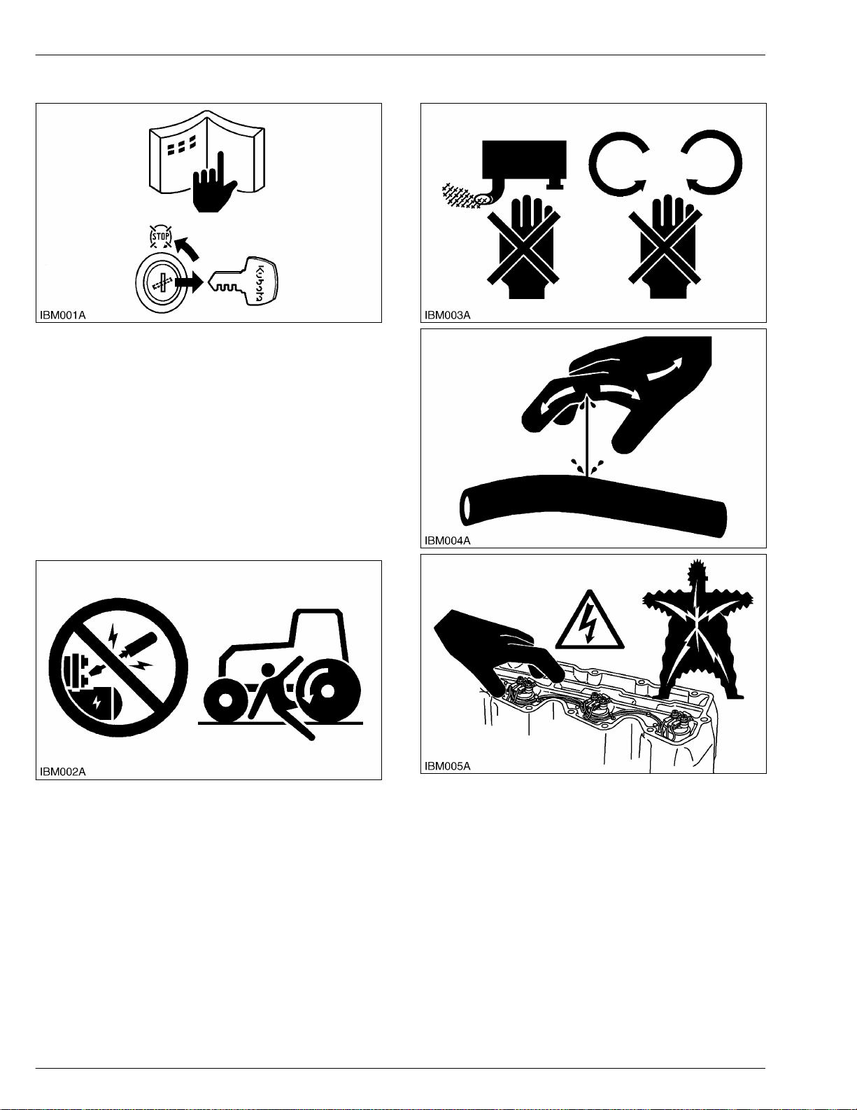
1. INFORMATION
1-2
BX23S, LA340, BT603, RCK54D, RCK60D, RCK54, RCK60B
KiSC issued 03, 2017 A
SAFETY FIRST
2. Before you start service
2. Before you start service
• Read all instructions and safety instructions in this
manual and on your machine safety decals.
• Clean the work area and machine.
• Park the machine on a stable
set the parking brake.
• Lower the implement to the ground.
• Stop the engine, then remove the key.
• Disconnect the battery negative cable.
• Hang a “DO NOT OPERATE” tag in the operator
station.
and level ground, and
4. Operate safely
3. Start safely
• Do not do the procedures below when you start the
engine.
1. Short across starter terminals.
2. Bypass the safety start switch.
• Do not alter or remove
system.
• Before you start the engine, make sure that all shift
levers are in neutral positions or in disengaged
positions.
• Do not start the engine when you stay on the
ground. Start the engine only from operator's seat.
any part of machine safety
• Do not use the machine after you consume alcohol
or medication or when you are tired.
• Put on applicable clothing and safety equipment.
• Use applicable tools only. Do
tools or parts.
• When 2 or more persons do servicing, make sure
that you do it safely.
• Do not touch the hot parts or parts that turn when
the engine operates.
• Do not remove the radiator cap when the engine
operates, or immediately after it stops. If not, hot
water can spout out from the radiator. Only remove
the radiator cap when it is at a sufficiently low
temperature to touch with bare hands. Slowly
not use alternative
Page 22
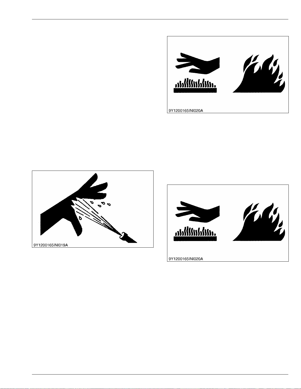
SAFETY FIRST
BX23S, LA340, BT603, RCK54D, RCK60D, RCK54, RCK60B
1-3
KiSC issued 03, 2017 A
5. Protect against high pressure spray 1. INFORMATION
loosen the cap to release the pressure before you
remove it fully
Released
•
can cause damage to the skin and cause serious
injury. Release the pressure before you disconnect
hydraulic or fuel lines. Tighten all connections
before you apply the pressure.
• Do not open a fuel system under high pressure.
The fluid under high pressure that stays in fuel lines
can cause serious injury. Do not disconnect or
repair the fuel lines, sensors, or any other
components between the fuel pump and injectors
on engines with a common rail fuel system under
high pressure.
• Put on an applicable ear protective device
(earmuffs or earplugs) to prevent injury against loud
noises.
• Be careful about electric shock. The engine
generates a high voltage of more than DC100 V in
the ECU and is applied to the injector.
fluid
.
(fuel
hydraulic oil)
or
under
pressure
5. Protect against high pressure
spray
6. Avoid hot exhaust
• Servicing machine or attachments with engine
operating can result in
Avoid exposure and skin contact with hot exhaust
gases and components.
• Exhaust parts and streams become very hot during
operation. Exhaust gases and components reach
temperatures hot enough to burn people, ignite, or
melt common materials.
serious personal injury.
• Spray from high pressure nozzles can penetrate the
skin and cause serious injury. Keep spray from
contacting hands or body
• If an accident occurs, see a doctor immediately.
Any high pressure spray injected into the skin must
be surgically removed within a few hours or
gangrene may result.
Doctors unfamiliar with this type of injury should
reference a knowledgeable medical source.
.
7. Exhaust filter cleaning
• Servicing machine or attachments during exhaust
filter cleaning can result
Avoid exposure and skin contact with hot exhaust
gases and components.
• During auto or manual/stationary exhaust filter
cleaning operations, the engine will operate at
elevated idle and hot temperatures for an extended
period of time. Exhaust gases and exhaust filter
components reach temperatures hot enough to
burn people, or ignite, or melt common materials.
in serious personal injury.
Page 23
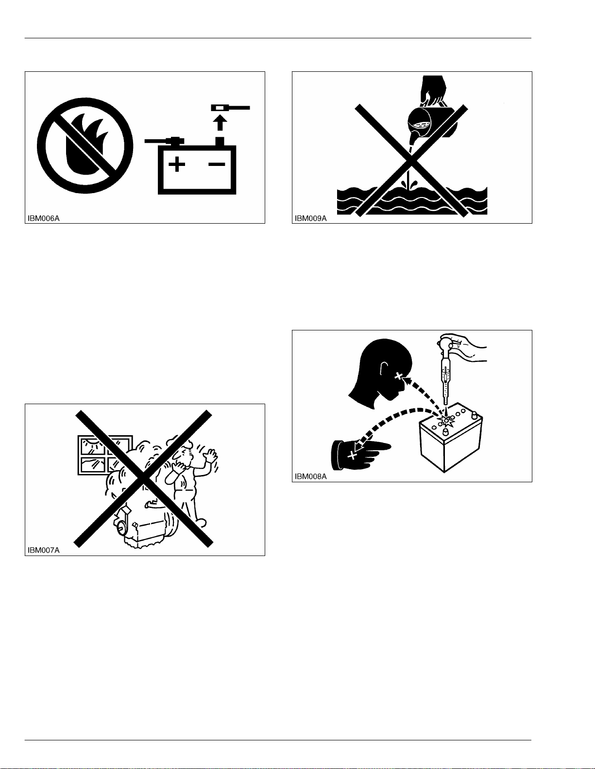
1. INFORMATION
1-4
BX23S, LA340, BT603, RCK54D, RCK60D, RCK54, RCK60B
KiSC issued 03, 2017 A
SAFETY FIRST
8. Prevent a fire
8. Prevent a fire
• Fuel is very flammable and explosive under some
conditions. Do not smoke or let flames or
your work area.
• To prevent sparks from an accidental short circuit,
always disconnect the battery negative cable first
and connect it last.
• The battery gas can cause an explosion. Keep the
sparks and open flame away from the top of
battery, especially when you charge the battery.
• Make sure that you do not spill fuel on the engine.
sparks in
10. Discard fluids correctly
• Do not discard fluids on the ground, down the drain,
into a stream, pond, or lake. Obey related
environmental
discard oil, fuel, coolant, electrolyte and other
dangerous waste.
protection regulations when you
11. Prevent acid burns
9. Keep a good airflow in the
work area
• If the engine is in operation, make sure that the
area has good airflow. Do not operate
a closed area. The exhaust gas contains poisonous
carbon monoxide.
the engine in
• Keep electrolyte away from your eyes, hands and
clothing. Sulfuric acid in battery electrolyte is
poisonous and
and cause blindness. If you spill electrolyte on
yourself, clean yourself with water, and get medical
aid immediately.
it can burn your skin and clothing
Page 24
SAFETY FIRST
BX23S, LA340, BT603, RCK54D, RCK60D, RCK54, RCK60B
1-5
KiSC issued 03, 2017 A
12. Prepare for emergencies 1. INFORMATION
12. Prepare for emergencies
• Keep a first aid kit and fire extinguisher ready at all
times.
• Keep the emergency contact telephone numbers
near your telephone at all times.
Page 25

1. INFORMATION
1-6
BX23S, LA340, BT603, RCK54D, RCK60D, RCK54, RCK60B
KiSC issued 03, 2017 A
SAFETY FIRST
Page 26

SAFETY LABEL
BX23S, LA340, BT603, RCK54D, RCK60D, RCK54, RCK60B
1-7
KiSC issued 03, 2017 A
1. Safety labels for BX tractor 1. INFORMATION
SAFETY LABEL
1. Safety labels for BX tractor
The safety labels are installed on the machine. If a label becomes damaged, illegible or is not on the machine, replace
it. The label part number is listed in the parts list.
Page 27

1. INFORMATION
1-8
BX23S, LA340, BT603, RCK54D, RCK60D, RCK54, RCK60B
KiSC issued 03, 2017 A
SAFETY LABEL
Page 28

SAFETY LABEL
BX23S, LA340, BT603, RCK54D, RCK60D, RCK54, RCK60B
1-9
KiSC issued 03, 2017 A
1. INFORMATION
Page 29

1. INFORMATION
1-10
BX23S, LA340, BT603, RCK54D, RCK60D, RCK54, RCK60B
KiSC issued 03, 2017 A
SAFETY LABEL
Page 30

SAFETY LABEL
BX23S, LA340, BT603, RCK54D, RCK60D, RCK54, RCK60B
1-11
KiSC issued 03, 2017 A
1. INFORMATION
Page 31

SAFETY LABEL
1-12
BX23S, LA340, BT603, RCK54D, RCK60D, RCK54, RCK60B
KiSC issued 03, 2017 A
1. INFORMATION
2.Safety labels for mower
2. Safety labels for mower
The safety labels are installed on the mower. If a label becomes damaged, illegible or is not on the mower, replace it.
The label part number is listed in the parts list.
Page 32

SAFETY LABEL
BX23S, LA340, BT603, RCK54D, RCK60D, RCK54, RCK60B
1-13
KiSC issued 03, 2017 A
3.Safety labels for loader 1. INFORMATION
3. Safety labels for loader
The safety labels are installed on the loader. If a label becomes damaged, illegible or is not on the loader, replace it.
The label part number is listed in the parts list.
Page 33

1. INFORMATION
1-14
BX23S, LA340, BT603, RCK54D, RCK60D, RCK54, RCK60B
KiSC issued 03, 2017 A
SAFETY LABEL
Page 34

SAFETY LABEL
BX23S, LA340, BT603, RCK54D, RCK60D, RCK54, RCK60B
1-15
KiSC issued 03, 2017 A
4.Safety labels for backhoe 1. INFORMATION
4. Safety labels for backhoe
The safety labels are installed on the backhoe. If a label becomes damaged, illegible or is not on the backhoe, replace
it. The label part number is listed in the parts list.
Page 35

1. INFORMATION
1-16
BX23S, LA340, BT603, RCK54D, RCK60D, RCK54, RCK60B
KiSC issued 03, 2017 A
SAFETY LABEL
Page 36

SPECIFICATIONS
BX23S, LA340, BT603, RCK54D, RCK60D, RCK54, RCK60B
1-17
KiSC issued 03, 2017 A
1.BX tractor specifications 1. INFORMATION
SPECIFICATIONS
1. BX tractor specifications
Model BX23S
PTO power
*1
Engine
Capacities
Dimensions
Traveling system
13.2 kW (17.7 HP)
Maker KUBOTA
Model D902
Type Liquid-cooled, 4-cycle diesel
Number of cylinders 3
Bore and stroke 72.0 × 73.6 mm (2.83 × 2.90 in.)
Total displacement 898 cm3 (54.8 cu. in.)
Engine gross power
Rated revolution 55.0 to 58.3 r/s (3300 to 3500 rpm)
Low idling revolution 1350 to 1550 rpm
Maximum torque 56.1 N⋅m (41.4 lbf⋅ft)
Battery 12 V, CCA: 560 A, RC: 86 min.
Fuel
Fuel tank 25 L (6.6 U.S.gals.)
Engine crankcase (with filter) 3.3 L (3.5 U.S.qts.)
Engine coolant 3.1 L (3.3 U.S.qts.)
Recovery tank 0.4 L (0.4 U.S.qts.)
Transmission case 11.3 L (2.99 U.S.gals.)
Overall length (without 3p) 2210 mm (87.01 in.)
Overall length (with 3p) 2515 mm (99.02 in.)
Overall width (Min. tread) 1145 mm (45.08 in.)
Overall height
Wheel base 1400 mm (55.12 in.)
Min. ground clearance 148 mm (5.83 in.)
Tread
Weight (with ROPS) 725 kg (1600 lbs)
Clutch N/A
Tire
Steering Hydrostatic type power steering
Transmission
*2
Diesel fuel No.1 [below -10 ℃ (14 ℉)]
Diesel fuel No.2 [above -10 ℃ (14 ℉)]
(with ROPS) 2190 mm (86.22 in.)
(Top of seat) 1255 mm (49.41 in.)
Front 930 mm (36.6 in.)
Rear 820 mm (32.2 in.)
Front: Turf/Bar/industrial 18 × 8.50-10
Rear: Turf/Bar/industrial 26 × 12.00-12
Main: Hydrostatic transmission, High-Low
17.1 kW (23.0 HP)
gear shift (2 forward, 2 reverse)
(Continued)
Page 37

1. INFORMA
1-18
BX23S, LA340, BT603, RCK54D, RCK60D, RCK54, RCK60B
KiSC issued 03, 2017 A
TION
Traveling system
Hydraulic unit
PTO
Manufacturer's estimate
*1
*2
SAE J1995
See and check "Implement limitation tables".
*3
SPECIFICA
Model BX23S
Brake Wet disk type
Min. turning radius 2.3 m (7.5 ft)
Hydraulic control system
Pump capacity 23.5 L/min. (6.21 gals/min)
System pressure
3-point hitch SAE Category 1
Max. lift force
*3
At lift points 5390 N (1212 lbs)
24 in. behind lift points 3040 N (680.4 lbs)
Remote control valve coupler (Rear: Option)
Remote control valve coupler (Front: Option)
System 2 valves
Coupler ISO 7241-1 series A
System 2 valves
Coupler (Fitting) ISO 7241-1 series B
PTO shaft SAE 1-3/8, 6 splines
Rear PTO
Revolution STD (2500 rpm)
PTO shaft
Mid PTO
Revolution STD (2500 rpm)
Directional control, auto-return lever sys-
tem
12.3 to 12.8 MPa (126 to 130 kgf/cm2)
[1790 to 1850 psi]
USA No. 5 (KUBOTA 10-tooth) involute
spline
TIONS
Page 38

SPECIFICATIONS
BX23S, LA340, BT603, RCK54D, RCK60D, RCK54, RCK60B
1-19
KiSC issued 03, 2017 A
2.Mower specifications 1. INFORMATION
2. Mower specifications
Model RCK60D-26BX RCK54D-26BX
Suitable tractor BX23S
Mounting method
Adjustment of cutting height Dial gauge
Cutting width 1524 mm (60 in.) 1372 mm (54 in.)
Cutting height 25 to 102 mm (1.0 to 4.0 in.)
Mower 115 kg (250 lbs) 103 kg (227 lbs)
Weight
Mower with frame
*1
link
134 kg (295 lbs) 122 kg (269 lbs)
Blade spindle speed 44.1 r/s (2647 rpm) 49.5 r/s (2969 rpm)
Blade tip velocity 72.5 m/s (14271 fpm) 73.8 m/s (14527 fpm)
Blade length 523 mm (20.6 in.) 475 mm (18.7 in.)
Number of blades 3
Overall length 1000 mm (39.4 in.) 928 mm (36.5 in.)
Dimensions
Overall width 1930 mm (76.0 in.) 1780 mm (66.5 in.)
Overall height (Min.) 281 mm (11.0 in.)
Tire Industrial, turf
*1 Remove the frame link when rear attachment is on. Remove the frame link when snow attachment is on.
*2 Bar tires are prohibited from driving over mower deck.
Drive-over-quick-joint, parallel linkage
Drive-over-suspended-linkage
*2
Page 39

SPECIFICA
1-20
BX23S, LA340, BT603, RCK54D, RCK60D, RCK54, RCK60B
KiSC issued 03, 2017 A
1. INFORMA
TION
3.Loader specifications
3. Loader specifications
3.1 Loader specifications
Loader model LA340 and LA340S
Tractor model BX23S
Boom cylinder
Bucket cylinder
Control valve One detent float position, single bucket dump, power beyond circuit
Rated flow 14 L/m (3.7 GPM)
Maximum pressure 12.8 MPa (131 kg/cm2) [1860 psi]
Net weight (approximate) 217 kg (478 lbs)
Include the quick bucket 48 in.
*1
Bore 40 mm (1.6 in.)
Stroke 326 mm (12.8 in.)
Bore 65 mm (2.6 in.)
Stroke 196 mm (7.72 in.)
*1
TIONS
Page 40

SPECIFICATIONS
BX23S, LA340, BT603, RCK54D, RCK60D, RCK54, RCK60B
1-21
KiSC issued 03, 2017 A
3.Loader specifications 1. INFORMATION
3.2 Bucket specifications
Loader model LA340 LA340S
Model Square 48 in.
Type Rigid Quick hitch
Width 1219 mm (47.99 in.)
Depth 491 mm (19.3 in.) 470 mm (18.5 in.)
Height (M) 465 mm (18.3 in.) 523 mm (20.6 in.)
Length (N) 538 mm (21.2 in.) 586 mm (23.1 in.)
Capacity
Weight 60 kg (130 lbs.) 56 kg (120 lbs.)
Struck 0.14 m3 (4.9 cu.ft.) 0.13 m3 (4.6 cu.ft.)
Heaped 0.17 m3 (6.0 cu.ft.)
Page 41

1. INFORMATION
1-22
BX23S, LA340, BT603, RCK54D, RCK60D, RCK54, RCK60B
KiSC issued 03, 2017 A
3.3 Dimensional specifications of loader
Loader model LA340 LA340S
Tractor model BX23S
A Max. lift height (to bucket pivot pin) 1804 mm (71.02 in.)
B Max. lift height under level bucket 1662 mm (65.43 in.) 1664 mm (65.51 in.)
C Clearance with bucket dumped 1323 mm (52.09 in.) 1288 mm (50.71 in.)
D Reach at max. lift height (Dumping reach) 646 mm (25.4 in.) 677 mm (26.7 in.)
E Max. dump angle 0.785 rad (45°)
F Reach with bucket on ground 1392 mm (54.80 in.) 1438 mm (56.61 in.)
G Bucket roll-back angle 0.51 rad (29°)
H Digging depth 125 mm (4.92 in.) 122 mm (4.80 in.)
J Overall height in carrying position 990 mm (39.0 in.)
SPECIFICATIONS
3.Loader specifications
Page 42

SPECIFICATIONS
BX23S, LA340, BT603, RCK54D, RCK60D, RCK54, RCK60B
1-23
KiSC issued 03, 2017 A
3.Loader specifications 1. INFORMATION
3.4 Operational specifications of loader
Loader model LA340 LA340S
Tractor model BX23S
U Lift capacity (Bucket pivot pin, max. height) 335 kg (739 lbs) 278 kg (613 lbs)
V Lift capacity (500 mm forward, max. height) 231 kg (509 lbs) 192 kg (423 lbs)
W Lift capacity (Bucket pivot pin, 1500 mm height) 372 kg (820 lbs) 317 kg (699 lbs)
X Lift capacity (500 mm forward, 1500 mm height) 268 kg (591 lbs) 229 kg (505 lbs)
Y Breakout force (Bucket pivot pin) 6258 N (1407 lbs) 5719 N (1286 lbs)
Z Breakout force (500 mm forward) 4389 N (986.7 lbs) 4008 N (901.0 lbs)
VV Bucket roll-back force at max. height 4731 N (1064 lbs) 4431 N (996.1 lbs)
XX Bucket roll-back force at 1500 mm height 5557 N (1249 lbs) 5264 N (1183 lbs)
ZZ Bucket roll-back force at ground level 5456 N (1227 lbs) 5195 N (1168 lbs)
Raising time 3.3 s
Lowering time 2.5 s
Bucket dumping time 2.7 s
Bucket rollback time 2.3 s
Page 43

1. INFORMATION
1-24
BX23S, LA340, BT603, RCK54D, RCK60D, RCK54, RCK60B
KiSC issued 03, 2017 A
LA340
LA340S
SPECIFICATIONS
3.Loader specifications
(A) Height (mm)
(B) Lift capacity (kg)
(C) At pivot pin
(D) 500 mm forward of pivot pin
(E) Rollback force (kN)
Page 44

SPECIFICATIONS
BX23S, LA340, BT603, RCK54D, RCK60D, RCK54, RCK60B
1-25
KiSC issued 03, 2017 A
4.Backhoe specifications 1. INFORMATION
4. Backhoe specifications
4.1 Backhoe specifications
Digging force (Per SAE J49)
With bucket cylinder 8610 N (1936 lbs)
With dipperstick cylinder 5209 N (1171 lbs)
Cycle time (Seconds)
Boom cylinder, extend 4.5 s
Boom cylinder, retract 3.7 s
Swing cylinder, from 90 degrees to center 1.5 s
Dipperstick cylinder, extend 4.1 s
Dipperstick cylinder, retract 3.4 s
Bucket cylinder, extend 3.1 s
Bucket cylinder, retract 2.4 s
Stabilizer cylinder, max. height to ground 2.9 s
Stabilizer cylinder, ground to max. height 2.3 s
Hydraulic cylinders
Boom Dipperstick Bucket Stabilizer Swing
Rod diameter 3.0 cm (1.2 in.) 2.5 cm (0.98 in.) 2.5 cm (0.98 in.) 2.5 cm (0.98 in.) 3.0 cm (1.2 in.)
Cylinder bore 6.5 cm (2.6 in.) 6.0 cm (2.4 in.) 5.0 cm (2.0 in.) 6.0 cm (2.4 in.) 6.0 cm (2.4 in.)
Bucket sizes
Width SAE truck capacity SAE heaped capacity Number of teeth Weight
Trenching 8 in. 20.3 cm (7.99 in.) 0.009 m3 (0.317 cu.ft.) 0.011 m3 (0.388 cu.ft.) 2 10 kg (22 lbs)
Trenching
12 in.
Trenching 16
in.
30.5 cm (12.0 in.) 0.014 m3 (0.494 cu.ft.) 0.020 m3 (0.706 cu.ft.) 3 13 kg (29 lbs)
40.6 cm (16.0 in.) 0.020 m3 (0.706 cu.ft.) 0.029 m3 (1.024 cu.ft.) 3 16 kg (35 lbs)
Page 45

SPECIFICATIONS
1-26
BX23S, LA340, BT603, RCK54D, RCK60D, RCK54, RCK60B
KiSC issued 03, 2017 A
1. INFORMATION
4.Backhoe specifications
4.2 Backhoe dimensions
Model BT603
(A) Transport height 1719 mm (67.68 in.)
(B) Stabilizer spread-transport 1296 mm (51.02 in.)
(C) Ground clearance 240 mm (9.45 in.)
(E) Overall width 1128 mm (44.41 in.)
(F) Maximum digging depth 1889 mm (74.37 in.)
(G) Digging depth, 2 ft. flat bottom 1842 mm (72.52 in.)
(H) Digging depth, 8 ft. flat bottom 1059 mm (41.69 in.)
(J) Operating height, fully raised 2539 mm (99.96 in.)
(K) Loading height 1533 mm (60.35 in.)
(L) Loading reach 1016 mm (40.00 in.)
(M) Reach from swing pivot 2612 mm (102.8 in.)
(N) Swing pivot to rear axle center line 726 mm (28.6 in.)
(P) Bucket rotation 3.14 rad (180°)
(R) Stabilizer spread-operating 1862 mm (73.31 in.)
(A3) Angle of departure per SAE J1234 0.351 rad (20.1°)
(U) Leveling angle 0.19 rad (11°)
Swing arc 2.44 rad (140°)
NOTE
• The specifications are taken with KUBOTA BX23S tractor. (Tire size: Front 18×8.5-10, Rear 26×12.00-12)
Page 46

SPECIFICA
BX23S, LA340, BT603, RCK54D, RCK60D, RCK54, RCK60B
1-27
KiSC issued 03, 2017 A
TIONS
4.Backhoe specifications 1. INFORMATION
4.3 Backhoe lift capacity
The lift capacities shown are 87% of maximum lift
force, according to SAE definition.
[A] Rated lift capacity (over
end)-kg (lbs)
(A) 192 kg (423 lbs)
(B) 212 kg (467 lbs)
(C) 215 kg (474 lbs)
(D) 209 kg (461 lbs)
(E) 203 kg (448 lbs)
(F) 201 kg (443 lbs)
(G) 214 kg (472 lbs)
(H) 262 kg (578 lbs)
Page 47

1. INFORMATION
1-28
BX23S, LA340, BT603, RCK54D, RCK60D, RCK54, RCK60B
KiSC issued 03, 2017 A
SPECIFICATIONS
4.Backhoe specifications
Page 48

TRAVELING SPEEDS
BX23S, LA340, BT603, RCK54D, RCK60D, RCK54, RCK60B
1-29
KiSC issued 03, 2017 A
TRAVELING SPEEDS
Model BX23S
Tire size (Rear) 26 × 12.00-12
Speed control pedal Range gear shift lever (At max. engine rpm)
Forward
Reverse
Low
High
Low
High
1. INFORMATION
0 to 6.5 km/h
0 to 4.0 mph
0 to 13.5 km/h
0 to 8.38 mph
0 to 5.0 km/h
0 to 3.1 mph
0 to 10.5 km/h
0 to 6.52 mph
Page 49

1. INFORMATION
1-30
BX23S, LA340, BT603, RCK54D, RCK60D, RCK54, RCK60B
KiSC issued 03, 2017 A
Page 50

DIMENSIONS
BX23S, LA340, BT603, RCK54D, RCK60D, RCK54, RCK60B
1-31
KiSC issued 03, 2017 A
DIMENSIONS
1. INFORMATION
Page 51

1. INFORMATION
1-32
BX23S, LA340, BT603, RCK54D, RCK60D, RCK54, RCK60B
KiSC issued 03, 2017 A
Page 52

2. GENERAL
KiSC issued 03, 2017 A
Page 53

IDENTIFICATION
BX23S, LA340, BT603, RCK54D, RCK60D, RCK54, RCK60B
2-1
KiSC issued 03, 2017 A
1. Tractor identification 2. GENERAL
IDENTIFICATION
1. Tractor identification
1.1 Checking serial number and hour
meter
• When contacting your local KUBOTA distributor,
always specify engine serial number, tractor serial
number and hour meter reading.
(4) Engine serial number
(1) Tractor identification plate (2) Tractor serial number
(3) ROPS identification plate
(5) Hour meter
1.2 Cylinder number
The cylinder numbers of KUBOTA diesel engine are
designated as shown in the figure.
The sequence of cylinder numbers is given as No.1,
No.2 and No.3 starting from the gear case side.
Page 54

2. GENERAL
2-2
BX23S, LA340, BT603, RCK54D, RCK60D, RCK54, RCK60B
KiSC issued 03, 2017 A
IDENTIFICATION
2. Checking mower identification
2. Checking mower
identification
• When contacting your local KUBOTA distributor,
always specify mower serial number.
(1) Mower serial number
3. Checking loader identification
• When contacting your local KUBOTA distributor,
always specify loader serial number.
4. Checking backhoe
identification
• When contacting your local KUBOTA distributor,
always specify backhoe serial number.
(1) Backhoe serial number
(1) Loader serial number [A] Boom R.H. inside
Page 55

GENERAL PRECAUTIONS
BX23S, LA340, BT603, RCK54D, RCK60D, RCK54, RCK60B
2-3
KiSC issued 03, 2017 A
GENERAL PRECAUTIONS
• Before you disassemble or repair machine, make
sure that you always disconnect the ground cable
from the battery first.
Remove oil and dirt from parts before you measure.
•
• Use KUBOTA genuine parts for replacement to
keep the machine performance and to make sure of
safety.
• You must replace the gaskets and O-rings when
you assemble again. Apply grease (1) to new Orings or oil seals before you assemble.
• When you assemble the external or internal snap
rings, make sure that the sharp edge (3) faces
against the direction from which force (2) is applied.
• When inserting spring pins, their splits must face
the direction from which a force is applied.
• To prevent damage to the hydraulic system, use
specified fluid or equivalent.
• Clean the parts before you measure them.
• Tighten the fittings to the specified torque. Too
much torque can cause damage to the hydraulic
units or the fittings. Not sufficient torque can cause
oil leakage.
• When you use a new hose or pipe, tighten the nuts
to the specified torque. Then loosen (approx. by
45°) and let them be stable before you tighten to
the specified torque (This is not applied to the parts
with seal tape.).
• When you remove the two ends of a pipe, remove
the lower end first.
• Use two pliers in removal and installation. One to
hold the stable side, and the other to turn the side
you remove to prevent twists.
• Make sure that the sleeves of flared connectors and
tapers of hoses are free of dust and scratches.
• After you tighten the fittings, clean the joint and
apply the maximum operation pressure 2 to 3 times
to check oil leakage.
2. GENERAL
(1) Grease
(2) Force
(3) Sharp edge
(4) Axial force
• When
you disassemble,
area
clean
to
make
(5) Rotating movement
(A) External circlip
(B) Internal circlip
carefully put the parts in a
easy
it
must install the screws, bolts and nuts in their initial
position to prevent the reassembly errors.
• When it is necessary to use special tools, use
KUBOTA special tools. Refer to the drawings when
you make special tools that you do not use
frequently.
to
find
the parts. You
Page 56

2. GENERAL
2-4
BX23S, LA340, BT603, RCK54D, RCK60D, RCK54, RCK60B
KiSC issued 03, 2017 A
Page 57

HANDLING PRECAUTIONS FOR ELECTRICAL PARTS AND WIRING
BX23S, LA340, BT603, RCK54D, RCK60D, RCK54, RCK60B
2-5
KiSC issued 03, 2017 A
2. GENERAL
HANDLING PRECAUTIONS FOR ELECTRICAL PARTS AND WIRING
IMPORTANT
• Check electrical wiring for damage and
loosened connection every year. To this end,
educate the customer to do his or her own
check and at the same time recommend the
dealer to perform periodic check for a fee.
• Do not try to modify or remodel any electrical
parts and wiring.
• When removing the battery cables, disconnect
the negative cable first. When installing the
battery cables, connect the positive cable first.
(1) Negative terminal (2) Positive terminal
To ensure safety and prevent damage to the machine
and
surrounding equipment, heed the following
precautions in handling electrical parts and wiring.
Page 58

2. GENERAL
2-6
BX23S, LA340, BT603, RCK54D, RCK60D, RCK54, RCK60B
KiSC issued 03, 2017 A
Page 59

LUBRICANTS, FUEL AND COOLANT
BX23S, LA340, BT603, RCK54D, RCK60D, RCK54, RCK60B
2-7
KiSC issued 03, 2017 A
1.BX tractor 2. GENERAL
LUBRICANTS, FUEL AND COOLANT
1. BX tractor
1.1 Lubricants, fuel, and coolant
IMPORTANT
•To prevent serious damage to hydraulic systems, use only KUBOT
No. Locations Capacities Grade
1
Fuel
2 Coolant with recovery tank
3 Engine crankcase
4 Transmission case
5 Front axle case
Greasing
Battery terminal 2 Moderate amount
6
Speed control pedal 1 Until grease overflow
Bonnet lock 1 Moderate amount
Bonnet guide 1 Moderate amount
*1
Oil amount when the oil level is at the upper level of the oil level gauge.
The product name of KUBOT
*2
*1
A genuine UDT fluid may be dif
25 L
6.6 U.S.gals
5.5 Imp.gals
3.1 L
3.3 U.S.qts
2.7 Imp.qts
3.3 L
3.5 U.S.qts
2.9 Imp.qts
11.3 L
2.99 U.S.gals
2.49 Imp.gals
3.6 L
3.8 U.S.qts
3.2 Imp.qts
No. of greasing
points
No. 2-D diesel fuel
•
•
No. 1-D diesel fuel if temperature is below -10 ℃ (14
Fresh clean soft water with anti-freeze
• Engine oil
API Service Classification CF or higher
Above 25 ℃ (77 ℉
-10 ℃ to 25 ℃ (14 ℉ to 77 ℉) SAE20, SAE10W-30, or 15W-40
Below -10 ℃ (14 ℉) SAE10W-30
• KUBOTA SUPER UDT-2 fluid
• KUBOTA SUPER UDT-2 fluid or SAE 80-SAE90 gear oil
Capacity Type of grease
ferent from that in the operator's manual depending on countries or territories.
A genuine fluid or its equivalent.
℉
)
) SAE30, SAE10W-30 or 15W-40
*2
*2
Multipurpose EP2 Grease (NLGI Grade No.
2)
Page 60

LUBRICANTS, FUEL AND COOLANT
2-8
BX23S, LA340, BT603, RCK54D, RCK60D, RCK54, RCK60B
KiSC issued 03, 2017 A
2. GENERAL
1.BX tractor
1.1.1 Fuel
• Use the ultra low sulfur diesel fuel only [below 0.0015 % (15 ppm)] for these engines.
• Cetane number of 45 minimum. Cetane number greater than
50 is preferred, especially for temperatures below
−20 °C (−4 °F) or elevations above 1500 m (5000 ft).
• Diesel fuels specified to EN 590 or ASTM D975 are recommended.
• No.2-D is a distillate fuel of lower volatility for engines in industrial and heavy mobile service. (SAE J313 JUN87)
1.1.2 Engine oil
• Oil used in the engine should have an American Petroleum Institute (API) service classification and Proper SAE
Engine Oil according to the ambient temperatures.
• Refer to the following table for the suitable API classification engine oil according to the engine type (with internal
EGR, external EGR or non-EGR) and the fuel.
Fuel used
Ultra Low Sulfur Fuel
[< 0.0015% (< 15 ppm)]
EGR:
Exhaust gas re-circulation
Oil class of engines except external EGR Oil class of engines with external EGR
CF, CF-4, CG-4, CH-4 or CI-4
Engine oil classification (API classification)
CF or CI-4
(Class CF-4, CG-4 and CH-4 engine oils cannot be used on EGR type engines)
• The CJ-4 engine oil is intended for diesel particulate filter (DPF) type engines, and cannot be used on this tractor.
1.1.3 Transmission oil
*KUBOTA Super UDT-2: For an
instead of standard hydraulic/transmission fluid.
Super UDT-2 is a proprietary KUBOTA formulation
conditions.
Regular UDT is also permitted for use in this machine.
• Indicated capacities of water and oil are manufacturer's estimate.
enhanced ownership experience, we highly recommend Super UDT-2 to be used
that deliveries superior performance and protection in all operating
Page 61

LUBRICANTS, FUEL AND COOLANT
BX23S, LA340, BT603, RCK54D, RCK60D, RCK54, RCK60B
2-9
KiSC issued 03, 2017 A
1.BX tractor 2. GENERAL
1.2 Overview of biodiesel fuel (BDF)
B0-B20 biodiesel fuels (BDF)
You can use mixed diesel fuels containing 20% or less biodiesel under the following conditions.
IMPORTANT
• Concentrations
aftertreatment device. Using concentrations greater than B5 (5%) can cause damage and reduce engine
life.
• Refuel and use the fuel with caution in order to avoid contact with the fuel and spillage that could create a
potential environmental or fire hazard. Wear appropriate protective equipment when refueling.
Applicable BDF
• You can use blended diesel fuels containing 6% through 20% BDF (B6-B20) which comply with American society
for testing and materials (ASTM) D7467 standard, as revised, without adversely affecting the performance and
durability of the engine and the components of the fuel system.
• Any mineral-oil-diesel-fuel, if used, must conform to ASTM D975 (or the European EN590) Standard, as revised.
B100 fuel used to generate biodiesel-blended-fuels must meet ASTM D6751 (or EN14214) Standard, as revised.
The final blended fuel B20 must conform to ASTM D7467 standard, as revised.
Straight-vegetable-oil is not allowed in any blended fuel.
• Allowable blended fuel is mineral-oil-diesel-fuel blended with B100 (for example 100% BDF).
The blended fuel ratio shall be less than 20% B100 and 80% or more diesel fuel.
Purchase the B100 source used for biodiesel blends from an accredited BQ-9000 marketer or producer.
You can find more information about qualified marketer(s) and producer(s) at http://www.bq-9000.org.
Product warranty, emission, and other precautions
• The engine-emission-control-system was certified according to current regulations based on the use of non-BDF.
When using BDF, the owner is advised to check applicable local and federal emission regulations, and comply
with all of them.
• BDF may cause restricted or clogged fuel filters during cold weather conditions, resulting in the engine not
operating properly.
• BDF encourages the growth of microorganisms which may cause degradation of the fuel. Degradation of the fuel
may cause corrosion of the fuel line or reduce the fuel filter flow earlier than expected.
• BDF inherently absorbs moisture which may cause degradation of the fuel earlier than expected. To avoid
absorbing moisture of BDF, drain the water separator and the fuel-filter-port often.
• Do not use biodiesel whose concentrations higher than 20% (for example, greater than B20).
Higher concentrated biodiesel will affect engine performance and fuel consumption, and degradation of the fuel
system components may occur.
• Do not readjust the engine-fuel-control-system because readjusting it will violate the emission-control-levels for
which the equipment was approved.
• Compared with soybean-based and rapeseed-based feedstock, palm-oil-based feedstock has a thicker
consistency (for example, higher viscosity) at lower temperatures.
Consequently, palm-oil-based feedstock may reduce performance of the fuel filter, particularly during cold weather
conditions.
• The KUBOTA warranty, as specified in the Owner's Warranty Information Guide, only covers flaws in product
materials and workmanship. Accordingly, The KUBOTA warranty do not cover any problems that may arise due to
the use of poor quality fuels that fail to meet the preceding requirements, whether biodiesel or mineral-oil-based.
Routine using
• Avoid spilling BDF onto painted surfaces because this may damage the finish. If the fuel is spilled, immediately
wipe clean and flush with soapy water to avoid permanent damage.
• When using BDF, you are advised to keep a full tank of the fuel, especially overnight and during short term
storage, to reduce condensation within the tank. Be sure to tighten the fuel cap after refueling to prevent moisture
build up within the tank. Water in the biodiesel mixture will damage the fuel filters and may damage the engine
components.
Maintenance requirements when using BDF B0 through B5
Extended oil-change-intervals may result in premature wear or engine damage.
Maintenance requirements when using BDF B6 through B20
The maintenance interval for fuel related parts changes.
greater
than
B5
(5%)
are
not approved
for
common rail engines and engines with
Page 62

LUBRICANTS, FUEL AND COOLANT
2-10
BX23S, LA340, BT603, RCK54D, RCK60D, RCK54, RCK60B
KiSC issued 03, 2017 A
2. GENERAL
1.BX tractor
See the following table for the new maintenance interval.
Items Interval Remarks
Fuel filter
Fuel hose
Check Every 50 hr
Replace Every 200 hr
Check Every 6 months
Replace Every 2 years
Replace if any deterioration (crack, hardening,
scar, or deformation) or damage occurred.
Consult your local KUBOTA Dealer for this
service.
Long term storage for B5
• BDF easily deteriorates due to oxygen, water, heat,
and foreign substances. Do not store B5 longer than three
months.
• When using B5 fuel and storing the machine longer than three months, drain the fuel from the tanks and replace
with light-mineral-oil-diesel-fuel. Subsequently, operate the engine at least the following minutes to remove all of
the biodiesel from the fuel lines.
Operating the engine 30 minutes
Long term storage for B6 through B20
• BDF easily deteriorates due to oxygen, water, heat,
and foreign substances. Do not store B6 through B20 longer
than one month.
• When using B6 through B20 fuel and storing the machine longer than one months, drain the fuel from the tanks
and replace with light-mineral-oil-diesel-fuel. Subsequently, operate the engine at least the following minutes to
remove all of the biodiesel from the fuel lines.
Operating the engine 30 minutes
Page 63

LUBRICANTS, FUEL AND COOLANT
BX23S, LA340, BT603, RCK54D, RCK60D, RCK54, RCK60B
2-11
KiSC issued 03, 2017 A
2.Mower 2. GENERAL
2. Mower
2.1 Lubricants
No. Place Capacity Lubricant
1 Gear box
Greasing
No. Place Capacity Type of grease
2 Universal joint
3 Three spindle shafts
4 Belt tension pulley
5 Belt tension pivot
7 Front and rear anti-scalp roller
Until grease overflows
0.36 L
0.38 U.S.qts
0.32 Imp.qts
• SAE 90 gear oil (API Service GL
—5 gear oil)
SAE multi-purpose type grease
NLGI-2 or NLGI-1 (GC-LB)
Page 64

2. GENERAL
2-12
BX23S, LA340, BT603, RCK54D, RCK60D, RCK54, RCK60B
KiSC issued 03, 2017 A
LUBRICANTS, FUEL AND COOLANT
2.Mower
Page 65

TIGHTENING TORQUES
BX23S, LA340, BT603, RCK54D, RCK60D, RCK54, RCK60B
2-13
KiSC issued 03, 2017 A
1.General use screws, bolts and nuts 2. GENERAL
TIGHTENING TORQUES
1. General use screws, bolts and nuts
Indication on
top of
bolt
Indication on
top of
nut
Materi-
al of
oppo-
nent
part
Unit N⋅m kgf⋅m lbf⋅ft N⋅m kgf⋅m lbf⋅ft N⋅m kgf⋅m lbf⋅ft N⋅m kgf⋅m lbf⋅ft N⋅m kgf⋅m lbf⋅ft
M6
M8 18 to 20
M10 40 to 45
M12 63 to 72
M14
M16
M18
M20
Ordinariness Aluminum Ordinariness Aluminum Ordinariness
7.9 to
108 to
167 to
246 to
334 to
0.80 to
9.3
11.0 to
125
17.0 to
191
25.0 to
284
34.0 to
392
No-grade or 4T 7T 9T
No-grade or 4T 6T
0.95
1.8 to
4.0 to
6.4 to
12.8
19.5
29.0
40.0
5.8 to
13 to 15 17 to 19
2.1
29 to 33 32 to 34
4.6
47 to 53 — — — 78 to 90
7.4
79.6 to
123 to
181 to
246 to
6.8
92.5
141
209
289
7.9 to
0.80 to
8.8
0.90
1.7 to
2.0
3.2 to
3.5
— — —
— — —
— — —
— — —
5.8 to
13 to 14 24 to 27
24 to 25
6.5
9.81 to
11.2
48 to 55
124 to
147
197 to
225
275 to
318
368 to
431
1.00 to
1.15
2.4 to
2.8
4.9 to
5.7
7.9 to
9.2
12.6 to
15.0
20.0 to
23.0
28.0 to
32.5
37.5 to
44.0
7.24 to
18 to 20 18 to 20
36 to 41 40 to 44
58 to 66 63 to 72
91.2 to
145 to
203 to
272 to
8.31
108
166
235
318
7.9 to
8.8
— — —
— — —
— — —
— — —
0.80 to
0.90
1.8 to
2.1
4.0 to
4.5
6.4 to
7.4
5.8 to
6.5
13 to 15 30 to 34
29 to 32 61 to 70
47 to 53
12.3 to
14.2
103 to
117
167 to
196
260 to
304
344 to
402
491 to
568
1.25 to
1.45
3.0 to
3.5
6.2 to
7.2
10.5 to
12.0
17.0 to
20.0
26.5 to
31.0
35.0 to
41.0
50.0 to
58.0
9.05 to
10.4
22 to 25
45 to 52
76.0 to
86.7
123 to
144
192 to
224
254 to
296
362 to
419
2. Stud bolts
Material of oppo-
nent part
Unit N⋅m kgf⋅m lbf⋅ft N⋅m kgf⋅m lbf⋅ft
M8 12 to 15 1.2 to 1.6 8.7 to 11 8.9 to 11 0.90 to 1.2 6.5 to 8.6
M10 25 to 31 2.5 to 3.2 18 to 23 20 to 25 2.0 to 2.6 15 to 18
M12 30 to 49 3.0 to 5.0 22 to 36 31 3.2 23
M14 62 to 73 6.3 to 7.5 46 to 54 — — —
M16 98.1 to 112 10.0 to 11.5 72.4 to 83.1 — — —
M18 172 to 201 17.5 to 20.5 127 to 148 — — —
Ordinariness Aluminum
Page 66

TIGHTENING TORQUES
2-14
BX23S, LA340, BT603, RCK54D, RCK60D, RCK54, RCK60B
KiSC issued 03, 2017 A
2. GENERAL
3.Metric screws, bolts and nuts
3. Metric screws, bolts and nuts
Grade Property class 8.8 Property class 10.9
Unit N⋅m kgf⋅m lbf⋅ft N⋅m kgf⋅m lbf⋅ft
M8 24 to 27 2.4 to 2.8 18 to 20 30 to 34 3.0 to 3.5 22 to 25
M10 48 to 55 4.9 to 5.7 36 to 41 61 to 70 6.2 to 7.2 45 to 52
M12 78 to 90 7.9 to 9.2 58 to 66 103 to 117 10.5 to 12.0 76.0 to 86.7
M14 124 to 147 12.6 to 15.0 91.2 to 108 167 to 196 17.0 to 20.0 123 to 144
M16 197 to 225 20.0 to 23.0 145 to 166 260 to 304 26.5 to 31.0 192 to 224
4. American standard screws, bolts and nuts with UNC or UNF
threads
Grade SAE GR.5 SAE GR.8
Unit N⋅m kgf⋅m lbf⋅ft N⋅m kgf⋅m lbf⋅ft
1/4 11.7 to 15.7 1.20 to 1.60 8.63 to 11.5 16.3 to 19.7 1.67 to 2.00 12.0 to 14.6
5/16 23.1 to 27.7 2.36 to 2.82 17.0 to 20.5 33 to 39 3.4 to 3.9 25 to 28
3/8 48 to 56 4.9 to 5.7 36 to 41 61 to 73 6.3 to 7.4 45 to 53
1/2 110 to 130 11.3 to 13.2 81.2 to 95.8 150 to 178 15.3 to 18.1 111 to 131
9/16 150 to 178 15.3 to 18.1 111 to 131 217 to 260 22.2 to 26.5 160 to 191
5/8 204 to 244 20.8 to 24.8 151 to 179 299 to 357 30.5 to 36.4 221 to 263
5. Plugs
Material of opponent part
Shape Size
N⋅m kgf⋅m lbf⋅ft N⋅m kgf⋅m lbf⋅ft
Tapered screw
Straight screw G1/4 25 to 34 2.5 to 3.5 18 to 25 — — —
R1/8 13 to 21 1.3 to 2.2 9.4 to 15 13 to 19 1.3 to 2.0 9.4 to 14
R1/4 25 to 44 2.5 to 4.5 18 to 32 25 to 34 2.5 to 3.5 18 to 25
R3/8 49 to 88 5.0 to 9.0 37 to 65 49 to 58 5.0 to 6.0 37 to 43
R1/2 58.9 to 107 6.00 to 11.0 43.4 to 79.5 59 to 78 6.0 to 8.0 44 to 57
G3/8 62 to 82 6.3 to 8.4 46 to 60 — — —
G1/2 49 to 88 5.0 to 9.0 37 to 65 — — —
Ordinariness Aluminum
Page 67

TIGHTENING TORQUES
BX23S, LA340, BT603, RCK54D, RCK60D, RCK54, RCK60B
2-15
KiSC issued 03, 2017 A
6.Adapters, elbows and others 2. GENERAL
6. Adapters, elbows and others
Item Thread size Tightening torque
Adjustable elbow,
adapter (O-ring port)
(UNF)
Hose fitting, flare nut
(UNF)
Adapter (NPT)
Grease fitting
NOTE
• When
mately 45 degrees (0.79 rad) and re-tighten it to specified torque.
connecting a hose
9/16 37 to 44 N⋅m 3.8 to 4.4 kgf⋅m 28 to 32 lbf⋅ft
3/4 48 to 54 N⋅m 4.9 to 5.5 kgf⋅m 36 to 39 lbf⋅ft
7/8 77 to 85 N⋅m 7.9 to 8.6 kgf⋅m 57 to 62 lbf⋅ft
9/16 25 to 28 N⋅m 2.6 to 2.8 kgf⋅m 19 to 20 lbf⋅ft
3/4 36 to 40 N⋅m 3.7 to 4.0 kgf⋅m 27 to 29 lbf⋅ft
7/8 43 to 50 N⋅m 4.4 to 5.0 kgf⋅m 32 to 36 lbf⋅ft
1/4 30 to 50 N⋅m 3.1 to 5.0 kgf⋅m 23 to 36 lbf⋅ft
3/8 39 to 60 N⋅m 4.0 to 6.1 kgf⋅m 29 to 44 lbf⋅ft
1/2 49 to 58 N⋅m 5.0 to 5.9 kgf⋅m 37 to 42 lbf⋅ft
1/8-27 4.1 to 6.7 N⋅m 0.42 to 0.69 kgf⋅m 3.0 to 5.0 lbf⋅ft
1/4-18 4.1 to 6.7 N⋅m 0.42 to 0.69 kgf⋅m 3.0 to 5.0 lbf⋅ft
with
flare
nut, after
tightening
the nut with specified torque, return it at approxi-
Page 68

2. GENERAL
2-16
BX23S, LA340, BT603, RCK54D, RCK60D, RCK54, RCK60B
KiSC issued 03, 2017 A
TIGHTENING TORQUES
Page 69

MAINTENANCE CHECK LIST
BX23S, LA340, BT603, RCK54D, RCK60D, RCK54, RCK60B
2-17
KiSC issued 03, 2017 A
1.BX tractor service intervals 2. GENERAL
MAINTENANCE CHECK LIST
1. BX tractor service intervals
Indication on hour meter
No. Items
1 Engine oil Change ◎ ○ ○ ○ every 200 Hr 2-25
2 Engine oil filter Replace ◎ ○ ○ ○ every 200 Hr 2-25
3 Transmission oil filter Replace ◎ ○ ○ ○ every 200 Hr 2-26
4 Transmission fluid Change ◎ ○ every 400 Hr 2-26
5 Transmission strainer Clean ◎ ○ every 400 Hr 2-27
6 Engine start system Check ○ ○ ○ ○ ○ ○ ○ ○ ○ ○ ○ ○ ○ ○ every 50 Hr 2-29
7 OPC system Check ○ ○ ○ ○ ○ ○ ○ ○ ○ ○ ○ ○ ○ ○ every 50 Hr 2-29
8 Greasing — ○ ○ ○ ○ ○ ○ ○ ○ ○ ○ ○ ○ ○ ○ every 50 Hr 2-27
9 Wheel bolt torque Check ○ ○ ○ ○ ○ ○ ○ ○ ○ ○ ○ ○ ○ ○ every 50 Hr 2-30
10 Lock lever Clean ○ ○ ○ ○ ○ ○ ○ ○ ○ ○ ○ ○ ○ ○ every 50 Hr 2-30
11 Battery condition Check ○ ○ ○ ○ ○ ○ ○ every 100 Hr 2-30
Clean ○ ○ ○ ○ ○ ○ ○ every 100 Hr 2-25
12 Air cleaner element
13 Fuel filter element
14 Fan belt Adjust ○ ○ ○ ○ ○ ○ ○ every 100 Hr 2-33
15 HST neutral spring Adjust ○ ○ ○ ○ ○ ○ ○ every 100 Hr 2-33
16 Brake pedal Adjust ○ ○ ○ ○ ○ ○ ○ every 100 Hr 2-34
17 Toe-in Adjust ○ ○ ○ every 200 Hr 2-36
18 Front axle case oil Change ○ every 400 Hr 2-38
19 Front axle pivot Adjust ○ every 400 Hr 2-36
20 Engine valve clearance Adjust every 800 Hr 2-39
Injection pressure of the
21
fuel injection nozzle
22 Cooling system Flush
23 Coolant Change
24 Injection pump Check
25 Radiator hose and clamp
26 Power steering oil line
27 Fuel line
28 Intake air line
Replace
Check ○ ○ ○ ○ ○ ○ ○ every 100 Hr 2-32
Replace ○ every 400 Hr 2-38
Check
Check every 1 year 2-41
Replace every 4 years 2-43
Check every 1 year 2-41
Replace every 4 years 2-43
Check every 1 year 2-42
Replace every 4 years 2-43
Check every 1 year 2-41
50 100 150 200 250 300 350 400 450 500 550 600 650 700
Since then
every
1000 Hr or
1 year
every
1500 Hr
every
2000 Hr or
2 years
every
2000 Hr or
2 years
every
3000 Hr
Ref-
eren
page
2-39
2-39 @
2-39
2-39
2-40
2-41 @
ce
*1
*1
*1
*1
*1
*B
*4
*4
*R
*R
*R
*R
(Continued)
@
@
@
@
Page 70

2. GENERAL
2-18
BX23S, LA340, BT603, RCK54D, RCK60D, RCK54, RCK60B
KiSC issued 03, 2017 A
MAINTENANCE CHECK LIST
No. Items
Indication on hour meter
50 100 150 200 250 300 350 400 450 500 550 600 650 700
Since then
Ref-
eren
ce
page
28 Intake air line Replace every 4 years 2-43 @
29 Engine breather hose
Check every 1 year 2-42
Replace every 4 years 2-43
30 Fuel system Bleed
31 Fuse Replace 2-43
Service as
required
*R
2-43
32 Light bulb Replace 2-44
IMPORTANT
• You must do the jobs indicated by ◎ after the first 50 hours of operation.
• The items which is @
marked are registered as the emission related critical parts by KUBOTA in the U.S.EPA nonroad emission regulation. As the engine owner, you are responsible for the performance of the required maintenance on the engine according to the
preceding instruction.
Please see Warranty Statement in detail.
*1 The initial 50 hours should not be a replacement (changing) cycle.
*B When the battery is used for less than 100 hours per year, check the battery condition by reading the indicator annually.
*2 You should clean the air cleaner more often in dusty conditions than in normal conditions.
*3 Every 1,000 hours or every 1 year whichever comes faster.
*4 Every 2,000 hours or every 2 years whichever comes faster.
*R Replace if any deterioration (crack, hardening, scar, or deformation) or damage occurred.
Page 71

MAINTENANCE CHECK LIST
BX23S, LA340, BT603, RCK54D, RCK60D, RCK54, RCK60B
2-19
KiSC issued 03, 2017 A
2.Mower service intervals 2. GENERAL
2. Mower service intervals
To keep the mower working in good condition as well as to avoid any accident and trouble, do periodic inspection and
maintenance. Check the following points before use.
No. Item
1 Oil leakage check ○ —
Make sure blade bolts are
2
tight.
3 Blade wear check ○ 2-45
4 Belt wear check ○ 2-45
5 All hardware check ○ —
Make sure that all pins are
6
in place.
7 Mower deck cleaning ○ —
Greasing
• Universal joint
• Three spindle shafts
• Belt tension pulley
8
• Belt tension pivot
• Front and rear antiscalp rollers
Frame link
•
9 Gear box oil check ○ 2-45
10 Gear box oil change ◎ ○ 2-47
11 Gear box oil seal check ○
12 Gear box oil seal replace ○ 2-48
Daily check Every 50 hrs Every 150 hrs Every 1 year Every 4 years
○
○
○
Service interval
Reference page
2-44
—
2-46
2-46
2-46
*1
2-47
IMPORTANT
• The jobs indicated by ◎ must be done after the first 50 hours of operation.
*1 Replace the gear box oil seal if any deterioration (crack, hardening, scar, or deformation) or damage occurred.
Page 72

2. GENERAL
2-20
BX23S, LA340, BT603, RCK54D, RCK60D, RCK54, RCK60B
KiSC issued 03, 2017 A
MAINTENANCE CHECK LIST
Page 73

CHECK AND MAINTENANCE
BX23S, LA340, BT603, RCK54D, RCK60D, RCK54, RCK60B
2-21
KiSC issued 03, 2017 A
1.Periodic service 2. GENERAL
CHECK AND MAINTENANCE
1. Periodic service
WARNING
To avoid serious injury or death:
• Do not work under any hydraulically supported
devices. Working under any hydraulically
supported devices can settle, suddenly leak
down, or be accidentally lowered.
• If necessary to work under the tractor or any
machine elements for servicing or adjustment,
securely support the tractor or any machine
elements with stands or suitable blocking
beforehand.
1.1 Opening bonnet
WARNING
• Never open the bonnet while the engine
operates.
• Do not touch the muffler or the exhaust pipes
while they are hot.
Touching the hot muffler or exhaust pipes could
cause severe burns.
1. Pull the guard forward.
2. Pull the bonnet open lever to release the latch to
open the bonnet, and open the bonnet.
Take the following precautions when checking
the tractor.
– Park the machine on firm and level ground.
– Set the parking brake.
– Lower the implement to the ground.
– Release all residual pressure of the
hydraulic system.
– Stop the engine and remove the key.
For your own safety and maximum service life of the
machine, make a thorough daily inspection before
operating the machine or starting the engine.
1.2.1 Walk around inspection
Look around and under the tractor for such items as
loose bolts, trash build-up, oil or coolant leaks, or
broken or worn parts.
1.2.2 Checking fuel gauge and refueling
WARNING
To avoid serious injury or death:
• Do not smoke while refueling.
• Be sure to stop the engine and remove the key
before refueling.
To avoid allergic skin reaction:
• Wash hands immediately after contact with
diesel fuel.
(1) Bonnet open lever
(2) Bonnet
(3) Front guard
(A) Pull
1.2 Daily check
WARNING
• To avoid serious injury or death:
IMPORTANT
• Do not permit dirt, trash, or water to get into the
fuel system.
• Be careful not to empty the fuel tank, otherwise
air will enter the fuel system, necessitating
bleeding before next starting the engine.
• Be careful not to spill the fuel during refueling.
If you should spill, wipe it off at once, or it may
cause a fire.
• To prevent water condensation and water
accumulation in the fuel tank, fill the tank before
parking overnight.
Using fuel
Temperature fuel
Above -10 ℃ (14 ℉) Grade No. 2-Diesel fuel
Below -10 ℃ (14 ℉) Grade No. 1-Diesel fuel
1. Turn the key switch to the ON position and check
the amount of fuel by the fuel gauge.
Page 74

2. GENERAL
2-22
BX23S, LA340, BT603, RCK54D, RCK60D, RCK54, RCK60B
KiSC issued 03, 2017 A
CHECK AND MAINTENANCE
1.Periodic service
2. Fill the fuel tank with fuel when the fuel gauge
shows as follows.
Amount of fuel for refueling 1/4 or less in the fuel tank
Fuel tank Capacity
(1) Fuel tank cap
25 L
6.6 U.S.gals.
1.2.3 Checking engine oil level
2. Check the engine oil before starting the engine, or,
after five minutes or more when the engine has
been stopped.
3. To check the engine oil level, draw out the dipstick,
wipe it clean, replace it, and draw it out again.
4. Check to see that the engine oil level lies between
the two notches.
5. If the engine oil level is too low, add new oil to the
prescribed level at the oil inlet.
(1) Oil inlet
(2) Dipstick
(A) Engine oil level is acceptable
within this range.
WARNING
To avoid serious injury or death:
• Be sure to stop the engine before checking the
engine oil level.
IMPORTANT
• When using an engine oil of different maker or
viscosity from the previous one, remove all of
the old oil and oil filter. Never mix two different
types of oil.
• If the engine oil level is low, do not operate the
engine.
• When using the BT603 Backhoe and checking
oil level, locate the tractor, the loader, and the
backhoe on a flat surface and set the loader and
the backhoe as illustrated as follows.
RELATED PAGE
LUBRICANTS, FUEL AND COOLANT on page 2-7
1.2.4 Checking transmission fluid level
WARNING
To avoid serious injury or death:
• Park the tractor on a firm, flat, and level surface,
lower the implement to the ground, and stop the
engine.
IMPORTANT
• If the transmission fluid level is low, do not
operate the engine.
1. To check the transmission fluid level, check the
dipstick as the following procedure.
a. Draw out the dipstick.
b. Wipe the dipstick clean.
c. Replace the dipstick.
d. Draw the dipstick out again.
2. Check to see that the transmission fluid level lies
between the two notches.
1. Park the machine on a firm, flat, and level surface.
Page 75

CHECK AND MAINTENANCE
BX23S, LA340, BT603, RCK54D, RCK60D, RCK54, RCK60B
2-23
KiSC issued 03, 2017 A
1.Periodic service 2. GENERAL
3. If the transmission fluid level is too low, add new
fluid to the prescribed level at the oil inlet.
(1) Oil inlet
(2) Dipstick
(A) Transmission fluid level is
acceptable within this range.
RELATED PAGE
LUBRICANTS, FUEL AND COOLANT on page 2-7
1.2.5 Checking coolant level
WARNING
To avoid serious injury or death:
• Be sure to stop the engine and remove the key
before checking coolant level.
• Do not remove the radiator cap while the
coolant is hot. When coolant is cool, slowly
rotate the radiator cap to the first stop and allow
sufficient time for excess pressure to escape
before removing the radiator cap completely.
IMPORTANT
• If the radiator cap has to be removed, follow the
preceding warning and securely retighten the
radiator cap.
• Use clean, fresh, soft water and anti-freeze to fill
the recovery tank.
1. Check to see that the coolant level is between the
“H” and “L” marks of the recovery tank.
2. When the coolant level drops due to evaporation,
add soft water only. In case of leakage, add
antifreeze and soft water in the specified mixing
ratio up to the “H” level.
(1) Recovery tank
(A) “H”
(B) “L”
RELATED PAGE
LUBRICANTS, FUEL AND COOLANT on page 2-7
1.2.6 Cleaning panel and radiator screen
WARNING
To avoid serious injury or death:
• Be sure to stop the engine and remove the key
before removing the screen.
• Before checking or cleaning the panel, wait long
enough until it cools down.
IMPORTANT
• The panel and the radiator screen must be clean
from debris to prevent the engine from
overheating and to allow good air intake for the
air cleaner.
• Be sure to reinstall the panel on the pillar
completely to prevent the invasion of dust.
• Be sure to stop the engine to avoid personal
injury and to allow good air intake for air
cleaner.
1. Check the panel and the radiator screen to be sure
that they are clean from debris.
Page 76

2. GENERAL
2-24
BX23S, LA340, BT603, RCK54D, RCK60D, RCK54, RCK60B
KiSC issued 03, 2017 A
CHECK AND MAINTENANCE
1.Periodic service
2. Remove the radiator screen, and then remove all
the foreign material.
NOTE
• If the dust or chaff is accumulated in the
battery compartment, open the panel and
clean completely.
(1) Panel
(2) Knob
(3) Center pillar
(4) Radiator screen
(A) Remove
1.2.7 Checking brake pedal
1. Inspect the brake pedal for free travel, and smooth
operation.
2. Adjust the brake pedal if incorrect measurement is
found.
1.2.8 Checking gauges, meters, and Easy
Checker
1. Inspect the instrument panel for broken gauge(s),
meter(s) and Easy Checker™ lamps.
2. Replace the gauge(s), the meter(s), or the Easy
Checker
™
™
if they are broken.
2. Replace the lights if they are broken.
1.2.10 Checking seat belt and ROPS
1. Always check condition of the seat belt and the
ROPS attaching hardware before operating the
tractor.
2. Replace the seat belt or the ROPS if it is damaged.
1.2.11 Checking and cleaning electrical
wiring and battery cables
WARNING
To avoid serious injury or death:
• A loosened terminal or connector, or damaged
wire may affect the performance of the electrical
components or cause short circuits. Leakage of
electricity could result in a fire hazard, a dead
battery, or damage to the electrical
components.
• Replace the damaged wires or connections
promptly.
• If a fuse blows soon after replacement, do not
use the capacity larger than recommended or
bypass the fuse system.
• Many wiring connections are protected by
waterproof plugs. Plug and unplug these
connections carefully and make sure that they
are sealed correctly after assembly.
• Accumulation of dust, chaff, and deposits of
spilled fuel around the battery, electrical wiring,
engine, or exhaust system may cause fire
hazards.
Clean around the battery, electrical wiring,
engine or exhaust system before starting to
work.
• To avoid premature electrical malfunctions, do
not apply high pressure water directly to the
battery, the wiring, the connectors, the electrical
components, or the instrument panel.
• Inspect the following check items regularly.
– Check the wiring for chafed or cracked
insulation.
– Check the wiring harness clamps. Replace
them if necessary.
– Check the connectors and the terminals for
looseness, contamination, or overheated or
discolored connections.
– Check the instrument panel for correct
operation of the switches and the gauges.
1.2.9 Checking head light, hazard light, and
tail light
1. Inspect the lights for broken bulbs and lenses.
Page 77

CHECK AND MAINTENANCE
BX23S, LA340, BT603, RCK54D, RCK60D, RCK54, RCK60B
2-25
KiSC issued 03, 2017 A
1.Periodic service 2. GENERAL
1.2.12 Checking movable parts
1. If any of the movable parts, such as levers and
pedals, is not smoothly moved because of rust or
sticky material, remove the rust or the sticky
material, and apply oil or grease on the relevant
spot.
Do not force the movable parts into motion.
Otherwise, the machine may get damaged.
1.3 Check points of initial 50 hours
1.3.1 Changing engine oil
WARNING
To avoid serious injury or death:
• Be sure to stop the engine and remove the key
before changing the oil.
• Oil can be hot and can burn. Allow the engine to
cool down sufficiently.
Engine oil with filter
Capacity
1. To drain the used engine oil, remove the drain plug
at the bottom of the engine, and drain the engine oil
completely into the oil pan.
2. After draining of the used engine oil, reinstall the
drain plug.
3. Fill the engine with the new engine oil up to the
upper notch on the dipstick.
4. Properly dispose of the used engine oil.
3.3 L
3.49 U.S.qts.
(1) Oil inlet
(2) Dipstick
(3) Drain plug
(A) Oil level is acceptable within
this range.
RELATED PAGE
LUBRICANTS, FUEL AND COOLANT on page 2-7
1.3.2 Replacing engine oil filter
WARNING
To avoid serious injury or death:
• Be sure to stop the engine before replacing the
oil filter cartridge.
• Oil can be hot and can burn. Allow the engine to
cool down sufficiently.
IMPORTANT
• To prevent serious damage to the engine, use
only a KUBOTA genuine filter.
1. Remove the oil filter.
2. Put a film of the clean engine oil on the rubber seal
of the new filter.
3. Tighten the filter quickly until it contacts the
mounting surface.
4. Tighten filter by hand an additional 1/2 turn only.
5. After the new filter has been replaced, the engine
oil normally decreases a little. Make sure that the
engine oil does not leak through the seal and be
sure to check the oil level on the dipstick.
6. Fill the engine with the engine oil up to the
prescribed level.
Page 78

2. GENERAL
2-26
BX23S, LA340, BT603, RCK54D, RCK60D, RCK54, RCK60B
KiSC issued 03, 2017 A
7. Properly dispose of the used engine oil.
(1) Engine oil filter
RELATED PAGE
LUBRICANTS, FUEL AND COOLANT on page 2-7
CHECK AND MAINTENANCE
1.Periodic service
(1) Filter
RELATED PAGE
LUBRICANTS, FUEL AND COOLANT on page 2-7
1.3.4 Changing transmission fluid
1.3.3 Replacing transmission oil filter
WARNING
To avoid serious injury or death:
• Be sure to stop the engine before changing the
transmission oil filter cartridge.
• Oil can be hot and can burn. Allow the engine to
cool down sufficiently.
IMPORTANT
• To prevent serious damage to the hydraulic
system, use only a KUBOTA genuine filter.
1. Remove the transmission oil filter.
2. Put a film of clean transmission oil on rubber seal of
new transmission oil filter.
3. Tighten the transmission oil filter quickly until it
contacts the mounting surface.
4. Tighten the transmission oil filter by hand an
additional 1/2 turn only.
5. After the new transmission oil filter has been
replaced, the transmission fluid level will decrease a
little. Make sure that the transmission fluid does not
leak through the seal, and check the fluid level.
6. Check the dipstick and refill with oil to prescribed
level.
7. Properly dispose of used oil.
WARNING
To avoid serious injury or death:
• Oil can be hot and can burn. Allow the engine to
cool down sufficiently.
1. To drain the used transmission fluid, remove the
drain plug at the bottom of the transmission case
and drain the transmission fluid completely into the
oil pan.
(1) Drain plug
2. After draining the transmission fluid, reinstall the
drain plug.
3. Clean the transmission strainer.
Page 79

CHECK AND MAINTENANCE
BX23S, LA340, BT603, RCK54D, RCK60D, RCK54, RCK60B
2-27
KiSC issued 03, 2017 A
1.Periodic service 2. GENERAL
4. Fill
with new transmission fluid up to the upper
notch on the dipstick.
(2) Oil inlet
(3) Dipstick
Transmission fluid Capacity
(A) Transmission fluid level is
acceptable within this range.
11.3 L
11.9 U.S.qts
9.94 Imp.qts
5. After operating the engine for a few minutes, stop it
and check the transmission fluid level again.
6. If the transmission fluid level is lower
than the
prescribed level shown on the dipstick (3), add fluid
to the prescribed level.
7. Properly dispose of used transmission fluid.
(1) Transmission strainer (2) Filter plate
IMPORTANT
• Do not operate the tractor immediately after
changing the transmission fluid.
Operate the engine
at medium speed for a few
minutes to prevent damage to the transmission.
RELATED PAGE
LUBRICANTS, FUEL AND COOLANT on page 2-7
1.3.5 Cleaning transmission strainer
1. When
changing the transmission fluid, disassemble
and rinse the transmission strainer with
nonflammable solvent to completely clean off filings.
When reassembling
the transmission strainer, be
careful not to damage the parts.
NOTE
• Since the fine filings in the oil can damage
the precision component parts of the
hydraulic system, the end of the suction line
is provided with an oil strainer.
1.4 Check points of every 50 hours
1.4.1 Greasing
NOTE
• If the machine is operated in extremely wet and
muddy
more often.
conditions, lubricate grease fittings
Page 80

2. GENERAL
2-28
BX23S, LA340, BT603, RCK54D, RCK60D, RCK54, RCK60B
KiSC issued 03, 2017 A
CHECK AND MAINTENANCE
1.Periodic service
1. Apply
a small amount of multipurpose grease to the
following points
(1) Speed control pedal
(2) Battery terminals
(3) Bonnet lock
(4) Bonnet guide rod
Page 81

CHECK AND MAINTENANCE
BX23S, LA340, BT603, RCK54D, RCK60D, RCK54, RCK60B
2-29
KiSC issued 03, 2017 A
1.Periodic service 2. GENERAL
The engine must not crank.
[Test 2] Switch for the PTO clutch lever
1. Make sure that the range gear shift lever is set in
the neutral position.
2. Make sure that the speed control pedal is set in the
neutral position.
3. Shift the PTO clutch lever to the on position.
4. Turn the key to the start position.
The engine must not crank.
(3) Bonnet lock
[A] Figure (A)
[B] Figure (B)
[C] Figure (C)
[D] Figure (D)
RELATED PAGE
LUBRICANTS, FUEL AND COOLANT on page 2-7
1.4.2 Checking engine start system
WARNING
To avoid serious injury or death:
• Do not allow anyone near the tractor while
testing.
• If the tractor does not pass the test, do not
operate the tractor.
Preparation before testing
1. Sit on the operator's seat.
2. Set the parking brake and stop the engine.
3. Shift the range gear shift lever to the neutral
position.
4. Check whether the speed control pedal is in the
neutral position.
5. Shift the PTO clutch lever to the off position.
[Test 1] Switch for the speed control pedal
1. Make sure that the range gear shift lever is set in
the neutral position.
2. Depress the speed control pedal.
3. Turn the key to the start position.
(1) Range gear shift lever (Hi-
Lo)
(2) PTO clutch lever
(3) Speed control pedal
1.4.3 Checking operator presence control
(OPC) system
WARNING
To avoid serious injury or death:
• Do not allow anyone near the tractor while
testing.
• If the tractor does not pass the test, do not
operate the tractor.
Preparation before testing
1. Sit on the operator's seat.
2. Set the parking brake and stop the engine.
3. Shift the range gear shift lever to the neutral
position.
4. Check whether the speed control pedal is in the
neutral position.
5. Shift the PTO clutch lever to the off position.
[Test 1] Switches for the operator's seat and the
speed control pedal
1. Start the engine.
2. Depress the speed control pedal.
3. Stand up.
Do not get off the machine.
The engine must stop after approximately one
second.
[Test 2] Switches for the operator's seat and the
PTO clutch lever
1. Start the engine.
2. Engage the PTO clutch lever.
Page 82

2. GENERAL
2-30
BX23S, LA340, BT603, RCK54D, RCK60D, RCK54, RCK60B
KiSC issued 03, 2017 A
3. Stand up.
Do not get off the machine.
The engine must stop after approximately one
second.
CHECK AND MAINTENANCE
1.Periodic service
(1) Front wheel bolt (2) Rear wheel bolt
(1) Range gear shift lever (Hi-
Lo)
(2) PTO clutch lever
(3) Speed control pedal
1.4.4 Checking wheel bolt torque
WARNING
To avoid serious injury or death:
• Never operate the tractor with a loose rim,
wheel, or axle.
• Any time bolts are loosened, retighten to the
specified torque.
• Check all bolts frequently and keep them tight.
1. Check the wheel bolts regularly especially when
new.
2. If they are loose, tighten them as follows.
Front wheel bolt
Tightening torque
Rear wheel bolt
149.2 to 179.0 N⋅m
15.2 to 18.3 kgf⋅m
110 to 132 lbf⋅ft
108.5 to 130.2 N⋅m
11.1 to 13.3 kgf⋅m
80 to 96 lbf⋅ft
1.4.5 Cleaning lock lever shaft
1. Before you use the lock lever, clean the lever
movable area (1).
(1) Lever movable area
1.5 Check points of every 100 hours
1.5.1 Checking battery condition
DANGER
To avoid the possibility of battery explosion:
For the refillable type battery, follow the
instructions below.
• Do not use or charge the refillable type battery
if the fluid level is below the “LOWER” (lower
limit level) mark. Otherwise, the battery
component parts may prematurely deteriorate,
which may shorten the battery's service life or
cause an explosion.
Page 83

CHECK AND MAINTENANCE
BX23S, LA340, BT603, RCK54D, RCK60D, RCK54, RCK60B
2-31
KiSC issued 03, 2017 A
1.Periodic service 2. GENERAL
• Check the fluid level regularly and add distilled
water as required so that the fluid level is
between the “UPPER” and “LOWER” levels.
DANGER
To avoid serious injury or death:
• When the battery is being activated, hydrogen
and oxygen gases in the battery are extremely
explosive. Keep open sparks and flames away
from the battery at all times, especially when
charging the battery.
WARNING
To avoid serious injury or death:
• Batteries, battery posts, terminals and related
accessories contain lead and lead compounds,
and other chemicals known to the State of
California to cause cancer and birth problems
or other reproductive harm. Wash hands after
handling.
• Never remove the battery cap while the engine
operates.
• Keep electrolyte away from eyes, hands and
clothes. If you are spattered with it, wash it
away completely with water immediately and
get medical attention.
• Keep open sparks and flames away from the
battery at all times. Hydrogen gas mixed with
oxygen becomes very explosive.
• Wear eye protection and rubber gloves when
working around battery.
high heat or improper regulator setting. Use a voltmeter
to check the state of charge. See reference chart below
to determine if charging is necessary.
Battery voltage Reference state of charge
12.6 V 100% (Full charge)
12.4 V 75%
12.2 V 50%
12.0 V 25%
11.8 V 0%
Battery charging
DANGER
To avoid serious injury or death:
• When the battery is being activated, hydrogen
and oxygen gases in the battery are extremely
explosive. Keep open sparks and flames away
from the battery at all times, especially when
charging the battery.
WARNING
To avoid serious injury or death:
• When disconnecting the cable from the battery,
start with the negative terminal first. When
connecting the cable to the battery, start with
the positive terminal first.
• Never check battery charge by placing a metal
object across the posts. Use a voltmeter or
hydrometer.
IMPORTANT
• The factory-installed battery is of non-refillable
type. If the battery is weak, charge the battery or
replace it with new one.
• Mishandling the battery shortens the service life
and adds to maintenance costs.
The original battery is maintenance free, but
needs some servicing.
If the battery is weak, the engine will be difficult
to start and the lights will be dim. It is important
to check the battery periodically.
• When exchanging an old battery for new one,
use battery of equal specification in table
below.
Battery
type
526RMF 12 V 86 min. 560 8.6 A
Volts
Reserve
capacity
Cold
cranking
amps
Normal
charging
rate
Maintenance-free, non-accessible batteries are
designed to eliminate the need to add water. Yet the
volume of electrolyte above plates may eventually
become depleted due to abnormal conditions such as
(1) Battery (2) Clamp
1. To slow charge the battery, connect the battery
positive terminal to the charger positive terminal
and the negative to the negative, then charge for at
least 1 hour at 6.5 amperes.
2. A boost charge is only for emergencies. It will
partially charge the battery at a high rate and in a
short time. When using a boost-charged battery, it
is necessary to recharge the battery as early as
Page 84

2. GENERAL
2-32
BX23S, LA340, BT603, RCK54D, RCK60D, RCK54, RCK60B
KiSC issued 03, 2017 A
possible. Failure to do this will shorten the battery's
service life.
3. When the specific gravity of electrolyte is between
1.27 and 1.29 the charging is completed.
Battery for storage
1. When storing the machine for a long period,
remove the battery from machine, adjust the
electrolyte to the proper level and store in a dry
place out of direct sunlight.
2. The battery self-discharges while it is stored.
Recharge it once every 3 months in hot seasons
and once every 6 months in cold seasons.
CHECK AND MAINTENANCE
1.Periodic service
1.5.2 Cleaning air cleaner element
WARNING
To avoid serious injury or death:
• Be sure to stop the engine and remove the key
before cleaning the air cleaner element.
IMPORTANT
• The air cleaner uses a dry element. Never apply
oil to the air cleaner.
• Do not operate the engine with filter element
removed.
• Align the arrow marks when reinstalling the
cover. If the cover is improperly fitted, dust
passes by the baffle and directly adheres to the
air cleaner element.
NOTE
• Check to see if the evacuator valve is blocked
with dust.
Open the evacuator valve once a week under
ordinary conditions or daily when used in a
dusty place to get rid of large particles of dust
and dirt.
Cleaning dust from the air cleaner element
1. Remove the air cleaner cover and the element.
2. When dry dust adheres to the element, blow
compressed air from the inside, turning the
element. Pressure of compressed air must be
below 205 kPa (2.1 kgf/cm
Cleaning carbon or oil from the air cleaner element
1. Remove the air cleaner cover and the element.
2. Soak the air cleaner element in detergent for 15
minutes.
3. Then wash it several times in water.
4. Rinse the air cleaner element with clean water.
5. Dry the air cleaner element naturally.
6. After the air cleaner element is fully dried, inspect
inside of it with a light and check if it is damaged or
not.
Refer to the instructions on the label attached to the
case.
2
, 30 psi).
(1) Element
(2) Cover
(3) Evacuator valve
1.5.3 Checking fuel filter
WARNING
To avoid serious injury or death:
• Stop the engine and remove the key before
checking the fuel lines and the fuel filter.
• Check the fuel lines periodically. The fuel lines
are subject to wear and aging. Fuel may leak
out onto the running engine, causing a fire.
IMPORTANT
• When the fuel line is disconnected for
maintenance or repair, plug both ends of the
fuel line with a clean plug of suitable size to
prevent dust and dirt from entering. You must
take particular care of the fuel filter in order to
avoid dust and dirt getting into the fuel system.
Entrance of dust and dirt causes malfunction of
the fuel pump.
The fuel line is made of rubber and ages regardless of
service period.
1. Inspect the fuel filter.
2. After inspection of the fuel filter, if the fuel line and
clamps are found damaged or deteriorated, replace
them.
Page 85

CHECK AND MAINTENANCE
BX23S, LA340, BT603, RCK54D, RCK60D, RCK54, RCK60B
2-33
KiSC issued 03, 2017 A
1.Periodic service 2. GENERAL
3. Check the fuel filter. If the fuel filter is clogged by
debris or contaminated by water, replace it.
(1) Pipe clamps
(2) Fuel line
(3) Fuel filter
(4) Fuel pump
NOTE
• If the fuel line is removed, be sure to properly
bleed the fuel system.
1.5.4 Adjusting fan belt tension
WARNING
To avoid serious injury or death:
• Be sure to stop the engine and remove the key
before checking the fan belt tension.
1. Stop the engine and remove the key.
2. Apply moderate thumb pressure to belt between
pulleys.
A deflection of between 7
to 9 mm (0.28 to 0.35 in.)
when the belt is pressed
in the middle of the span.
Fan belt tension
Factory specification
alternator out until the deflection of the belt falls
within acceptable limits.
(1) Bolt (A) Check the belt tension.
4. Replace fan belt if it is damaged.
1.5.5 Adjusting HST neutral spring
WARNING
• Do not operate if tractor moves on level ground
with foot off speed control pedal.
• If tractor moves on level ground with foot off
the pedal, or, if the pedal is too slow in
returning to neutral position when removing the
foot from the pedal, adjust the HST neutral
spring.
The HST neutral spring located under the front right
side of the fender can adjust returning speed of speed
control pedal. Since the HST neutral spring tension is
weakened, the HST tension should be checked and
adjusted every 100 hours.
Checking the HST neutral spring tension: Dynamic
braking
1. Start the engine and hold the maximum engine
speeds.
2. Operate the machine on the concrete level ground.
3. Shift the range gear shift lever to hi position.
4. Depress the speed control pedal to forward.
5. Release the foot from the speed control pedal.
6. Check the distance between the foot releasing point
(A) and the machine stopping point (B). If distance
(L) is more than approximately 3 m (10 ft.),
strengthen the HST neutral spring tension so that
the machine will stop in approximately 3 m (10 ft.)
after releasing the foot from the speed control
pedal.
3. If tension is incorrect, loosen the alternator
mounting bolts and, using a lever placed between
the alternator and the engine block, pull the
Page 86

2. GENERAL
2-34
BX23S, LA340, BT603, RCK54D, RCK60D, RCK54, RCK60B
KiSC issued 03, 2017 A
CHECK AND MAINTENANCE
1.Periodic service
• Even if free travel of the brake pedal is within
the limitation, adjust the brake pedal.
1. Release the parking brake.
2. Loosen the lock nut and turn the turnbuckle to
adjust the rod length so that the brake free travel is
10 mm (0.4 in.).
3. Extend the turnbuckle one additional turn.
4. Retighten the lock nut.
5. Depress the brake pedal several times and make
sure that free travel is inside factory specification.
(A) Foot releasing point
(B) Machine stopping point
(L) Distance between foot re-
leasing point and the machine stopping point
Adjusting the HST neutral spring tension: Dynamic
braking
1. Remove the step from the machine.
2. Loosen the lock nut (2).
(1) HST neutral spring
(2) Lock nut
(3) Adjusting nut
(4) Adjusting rod
(M) Length of adjusting rod from
stay
Brake pedal free
travel
Factory specification
25 to 35 mm
1.0 to 1.4 in.
3. Adjust the adjusting nut (3) on the adjusting rod (4).
4. Tighten the lock nut (2).
5. Start the engine and check dynamic brake as
mentioned former.
6. If the machine will not stop with dynamic brake in
approximately 3 m (10 ft.), adjust the neutral spring
again.
Length (M)
Factory specification
10 mm
0.39 in.
1.5.6 Adjusting brake pedal
WARNING
To avoid serious injury or death:
• Stop the engine, remove the key, lower the
implement to the ground, and chock the wheels
before checking the brake pedal.
(1) Lock nut
(2) Turnbuckle
(A) Free travel
(B) Right rear tire
1.6 Check point of every 200 hours
1.6.1 Replacing engine oil filter
WARNING
To avoid serious injury or death:
• Be sure to stop the engine before replacing the
oil filter cartridge.
• Oil can be hot and can burn. Allow the engine to
cool down sufficiently.
Page 87

CHECK AND MAINTENANCE
BX23S, LA340, BT603, RCK54D, RCK60D, RCK54, RCK60B
2-35
KiSC issued 03, 2017 A
1.Periodic service 2. GENERAL
IMPORTANT
• To prevent serious damage to the engine, use
only a KUBOTA genuine filter.
1. Remove the oil filter.
2. Put a film of the clean engine oil on the rubber seal
of the new filter.
3. Tighten the filter quickly until it contacts the
mounting surface.
4. Tighten filter by hand an additional 1/2 turn only.
5. After the new filter has been replaced, the engine
oil normally decreases a little. Make sure that the
engine oil does not leak through the seal and be
sure to check the oil level on the dipstick.
6. Fill the engine with the engine oil up to the
prescribed level.
7. Properly dispose of the used engine oil.
(1) Engine oil filter
1.6.2 Changing engine oil
WARNING
To avoid serious injury or death:
• Be sure to stop the engine and remove the key
before changing the oil.
• Oil can be hot and can burn. Allow the engine to
cool down sufficiently.
Engine oil with filter
Capacity
1. To drain the used engine oil, remove the drain plug
at the bottom of the engine, and drain the engine oil
completely into the oil pan.
2. After draining of the used engine oil, reinstall the
drain plug.
3. Fill the engine with the new engine oil up to the
upper notch on the dipstick.
4. Properly dispose of the used engine oil.
3.3 L
3.49 U.S.qts.
(1) Oil inlet
(2) Dipstick
(3) Drain plug
(A) Oil level is acceptable within
this range.
1.6.3 Replacing transmission oil filter
WARNING
To avoid serious injury or death:
• Be sure to stop the engine before changing the
transmission oil filter cartridge.
• Oil can be hot and can burn. Allow the engine to
cool down sufficiently.
IMPORTANT
• To prevent serious damage to the hydraulic
system, use only a KUBOTA genuine filter.
1. Remove the transmission oil filter.
2. Put a film of clean transmission oil on rubber seal of
new transmission oil filter.
3. Tighten the transmission oil filter quickly until it
contacts the mounting surface.
4. Tighten the transmission oil filter by hand an
additional 1/2 turn only.
5. After the new transmission oil filter has been
replaced, the transmission fluid level will decrease a
little. Make sure that the transmission fluid does not
leak through the seal, and check the fluid level.
Page 88

2. GENERAL
2-36
BX23S, LA340, BT603, RCK54D, RCK60D, RCK54, RCK60B
KiSC issued 03, 2017 A
6. Check the dipstick and refill with oil to prescribed
level.
7. Properly dispose of used oil.
CHECK AND MAINTENANCE
1.Periodic service
(1) Filter
1.6.4 Adjusting toe-in
WARNING
To avoid serious injury or death:
• Park the tractor on a firm, flat, and level place.
• Lower the implement to the ground, and apply
the parking brake.
• Stop the engine and remove the key.
Checking toe-in
1. Turn the steering wheel so that the front wheels are
in the straight ahead position.
2. Measure the distance between the tire beads at
front of the tires, and at the hub heights.
3. Measure the distance between the tire beads at
rear of the tires, and at the hub heights.
4. Front distance should be 0 to 5.0 mm (0 to 0.2 in.)
less that rear distance. If front distance is not
proper length, adjust the length of the tie rod.
(A) Wheel-to-wheel distance at
rear
(B) Wheel-to-wheel distance at
front
(C) Front
Adjusting toe-in
1. Loosen the lock nuts and turn the tie-rod to adjust
the rod length until the proper toe-in measurement
is obtained.
2. Retighten the lock nuts.
(1) Lock nut (2) Tie-rod
1.7 Check points of every 400 hours
Toe-in ((B) - (A))
Factory specification
0 to 5.0 mm
0 to 0.2 in.
1.7.1 Adjusting front axle pivot
WARNING
To avoid serious injury or death:
• Be sure to stop the engine and remove the key
before adjusting the front axle pivot.
If the front axle pivot pin adjustment is not correct, front
wheel vibration can occur causing vibration in the
steering wheel.
1. Remove the split pin and tighten the adjusting nut.
Tightening torque
2. Make sure that one of the nut slots aligns with the
split pin hole.
Adjusting nut
20 N⋅m
2.0 kgf⋅m
15 lbf⋅ft
Page 89

CHECK AND MAINTENANCE
BX23S, LA340, BT603, RCK54D, RCK60D, RCK54, RCK60B
2-37
KiSC issued 03, 2017 A
1.Periodic service 2. GENERAL
3. Tighten the nut slightly if necessary when aligning
the nut slots with the split pin hole.
4. Replace the split pin.
(1) Adjusting nut (2) Split pin
1.7.2 Changing transmission fluid
WARNING
To avoid serious injury or death:
• Oil can be hot and can burn. Allow the engine to
cool down sufficiently.
1. To drain the used transmission fluid, remove the
drain plug at the bottom of the transmission case
and drain the transmission fluid completely into the
oil pan.
(2) Oil inlet
(3) Dipstick
Transmission fluid Capacity
(A) Transmission fluid level is
acceptable within this range.
11.6 L
12.3 U.S.qts
10.2 Imp.qts
5. After operating the engine for a few minutes, stop it
and check the transmission fluid level again.
6. If the transmission fluid level is lower than the
prescribed level shown on the dipstick (3), add fluid
to the prescribed level.
7. Properly dispose of used transmission fluid.
IMPORTANT
• Do not operate the tractor immediately after
changing the transmission fluid.
Operate the engine at medium speed for a few
minutes to prevent damage to the transmission.
RELATED PAGE
LUBRICANTS, FUEL AND COOLANT on page 2-7
(1) Drain plug
2. After draining the transmission fluid, reinstall the
drain plug.
3. Clean the transmission strainer.
4. Fill with new transmission fluid up to the upper
notch on the dipstick.
Page 90

2. GENERAL
2-38
BX23S, LA340, BT603, RCK54D, RCK60D, RCK54, RCK60B
KiSC issued 03, 2017 A
1.7.3 Cleaning transmission strainer
1. When changing the transmission fluid, disassemble
and rinse the transmission strainer with
nonflammable solvent to completely clean off filings.
When reassembling the transmission strainer, be
careful not to damage the parts.
CHECK AND MAINTENANCE
1.Periodic service
(1) Transmission strainer (2) Filter plate
NOTE
• Since the fine filings in the oil can damage
the precision component parts of the
hydraulic system, the end of the suction line
is provided with an oil strainer.
(1) Breather plug
(2) Oil gauge with dipstick
(3) Drain plug
(A) Front axle case oil level is
acceptable within this range.
3. Drain the front-axle-case-oil completely into the oil
pan.
4. After draining the front-axle-case-oil, reinstall the
drain plugs.
5. Remove the right and left breather plugs.
6. Fill with new front-axle-case-oil up to the upper
notch on the dipstick.
Front axle case oil Capacity
4.7 L
5.0 U.S.qts
4.1 Imp.qts
IMPORTANT
• After 10 minutes, check the front-axle-caseoil level again. If the front-axle-case-oil level
is lower than the prescribed level, add the
front-axle-case-oil to prescribed level.
7. After filling with front-axle-case-oil, reinstall the oil
gauge and breather plugs.
RELATED PAGE
LUBRICANTS, FUEL AND COOLANT on page 2-7
1.7.4 Changing front axle case oil
WARNING
To avoid serious injury or death:
• Be sure to stop the engine and remove the key
before changing the front axle case oil.
1. Park the tractor on a firm, flat, and level place.
2. To drain the used front-axle-case-oil, remove the
right and left drain plugs and oil gauge at the front
axle case.
1.7.5 Replacing fuel filter element
NOTE
• If the fuel line is removed, be sure to properly
bleed the fuel system.
1. Disconnect the fuel hoses and replace the fuel filter
(2).
Page 91

CHECK AND MAINTENANCE
BX23S, LA340, BT603, RCK54D, RCK60D, RCK54, RCK60B
2-39
KiSC issued 03, 2017 A
1.Periodic service 2. GENERAL
2. Disconnect the fuel hoses and loosen the pipe
clamp to replace the fuel filter (5).
1.10 Check points of every 1500
hours
1.10.1 Checking injection pressure of fuel
injection nozzle
• See “Checking fuel injection pressure”.
RELATED PAGE
4.4.5 Checking fuel injection pressure on page 3-30
1.11 Check points of every 2000
hours or 2 years
1.11.1 Flushing cooling system and
changing coolant
WARNING
To avoid serious injury or death:
• Do not remove the radiator cap while the
coolant is hot. When the coolant is cool, slowly
rotate the radiator cap to the first stop and allow
sufficient time for excess pressure to escape
before removing the radiator cap completely.
(1) Fuel pump
(2) Fuel filter
(3) Fuel line
(4) Hose clamp
(5) Fuel filter
1.8 Check points of every 800 hours
1.8.1 Adjusting engine valve clearance
• See “Checking engine vale clearance”.
RELATED PAGE
4.1.2 Checking valve clearance on page 3-24
1.9 Check points of every 1000
hours or 1 year
Be sure to do the following servicing once every 1000
hours or yearly, whichever comes first.
1.9.1 Replacing air cleaner element
See “Cleaning air cleaner element”.
RELATED PAGE
1.5.2 Cleaning air cleaner element on page 2-32
IMPORTANT
• Do not start the engine without coolant.
• Use clean, fresh soft water and the anti-freeze
to fill the radiator and the recovery tank.
• When mixing the anti-freeze with water, the antifreeze mixing ratio is 50%.
• Securely tighten the radiator cap. If the radiator
cap is loose or improperly fitted, water may leak
out and the engine could overheat.
Coolant (with recovery tank)
1. Stop the engine and let it cool down.
2. To drain the coolant, open the radiator drain plug or
the engine drain plug and remove the radiator cap.
The radiator cap must be removed to completely
drain the coolant.
3. After all coolant is drained, close the drain plug.
4. Fill the radiator with clean soft water and the cooling
system cleaner.
5. Follow directions of the instruction of cooling
system cleaner.
6. After flushing the radiator, fill it with clean soft water
and the anti-freeze until the coolant level is just
below the radiator cap.
7. Install the radiator cap securely.
8. Fill the recovery tank with coolant up to the “H”
mark on the recovery tank.
9. Start and operate the engine for a few minutes.
Capacity
3.1 L
3.3 U.S.qts
2.7 Imp.qts
Page 92

2. GENERAL
2-40
BX23S, LA340, BT603, RCK54D, RCK60D, RCK54, RCK60B
KiSC issued 03, 2017 A
CHECK AND MAINTENANCE
1.Periodic service
10. Stop the engine and let it cool.
11. Check the coolant level of the recovery tank and
add the coolant if necessary.
• When using the antifreeze, put on some
protection such as rubber gloves. The
antifreeze contains poison.
• If someone drank antifreeze, seek immediate
medical help. Do not make a person throw up
unless told to throw up by poison-controlcenter or a health care professional. Use
standard first aid and CPR for signs of shock or
cardiac arrest. Call your local poison control
center or your local emergency number for
further assistance.
• When the antifreeze comes in contact with the
skin or clothing, wash it off immediately.
• Do not mix different types of the antifreeze. The
mixture can produce chemical reaction causing
harmful substances.
• The antifreeze is extremely flammable and
explosive under certain conditions. Keep fire
and children away from the antifreeze.
• When draining fluids from the engine, place
some container underneath the engine body.
• Do not pour waste onto the ground, down a
drain, or into any water source.
• Also, follow the relevant environmental
protection regulations when disposing of the
antifreeze.
(1) Radiator cap
(2) Radiator drain plug
(3) Engine drain plug
RELATED PAGE
LUBRICANTS, FUEL AND COOLANT on page 2-7
1.11.2 Antifreeze
Always use a 50/50 mix of long-life coolant and clean
soft water in KUBOTA engines.
NOTE
• The following data represent industry standards
that necessitate a minimum glycol content in
the concentrated antifreeze.
• Long-life coolant (hereafter LLC) comes in several
types. Use ethylene glycol (EG) type for this
engine.
• Before using LLC-mixed cooling water, fill the
radiator with fresh water and empty it again.
Repeat this procedure two times or three times to
clean up the inside.
• Mixing the LLC
Premix 50% LLC with 50% clean soft water.
When mixing, stir it up well, and then fill into the
radiator.
• Adding the LLC.
– Add only water if the mixture reduces in amount
by evaporation.
– If there is a mixture leak, add the LLC of the
same manufacturer and type in the same
mixture percentage.
WARNING
To avoid serious injury or death:
IMPORTANT
• Never add any long-life coolant of
different manufacturer. Different brands
may have different additive components,
Page 93

CHECK AND MAINTENANCE
BX23S, LA340, BT603, RCK54D, RCK60D, RCK54, RCK60B
2-41
KiSC issued 03, 2017 A
1.Periodic service 2. GENERAL
and the engine may fail to perform as
specified.
• When the LLC is mixed, do not use any radiator
cleaning agent. The LLC contains anticorrosive
agent. If mixed with the cleaning agent, sludge may
build up, adversely affecting the engine parts.
• KUBOTA's genuine long-life coolant has a service
life of two years.
Be sure to change the coolant every two years.
• The procedure for the mixing of water and the
antifreeze differs according to the make of the
antifreeze and the ambient temperature. Refer to
SAE J1034 standard, more specifically also to SAE
J814c.
(1) Hose (2) Hose clamps
Antifreeze Freezing point Boiling point
50Vol% -37 ℃ -34 ℉ 108 ℃ 226 ℉
*1 At 1.013 × 10⁵ Pa (760 mmHg) atmospheric pressure. A higher
boiling point is obtained by using a radiator pressure cap which
permits the development of pressure within the cooling system.
*1
1.12 Check points of every 3000
hours
1.12.1 Checking injection pump
• See “Fuel system” for checking injection pump.
RELATED PAGE
4. Fuel system on page 3-12
1.13 Check points of every 1 year
1.13.1 Checking intake air line
WARNING
To avoid serious injury or death:
• Stop the engine and remove the key before
checking the intake air line.
1.13.2 Checking radiator hoses and hose
clamps
WARNING
To avoid serious injury or death:
• Be sure to stop the engine and remove the key
before checking the radiator hose and the hose
clamps.
1. If the hose clamps are loose or water leaks, tighten
them securely.
2. Replace the radiator hoses and tighten the hose
clamps securely if you checked and found that the
radiator hoses are swollen, hardened, or cracked.
3. Properly dispose of used coolant.
1. Check to see that the hose and the hose clamps
are tight and not damaged.
2. If the hose and the clamps are found worn or
damaged, replace or repair them at once.
(1) Radiator hoses (2 pcs) (2) Hose clamps (4 pcs)
1.13.3 Checking power steering line
WARNING
To avoid serious injury or death:
• Be sure to stop the engine and remove the key
before checking the power steering line.
1. Check to see that all power steering lines are tight
and not damaged.
Page 94

2. GENERAL
2-42
BX23S, LA340, BT603, RCK54D, RCK60D, RCK54, RCK60B
KiSC issued 03, 2017 A
2. If the power steering pressure hoses are found to
be worn or damaged, replace or repair them at
once.
(1) Power steering pressure
hose
1.13.4 Checking fuel lines
CHECK AND MAINTENANCE
1.Periodic service
WARNING
To avoid serious injury or death:
• Stop the engine and remove the key before
checking the fuel lines and fuel filter.
• Check the fuel lines periodically. The fuel lines
are subject to wear and aging. Fuel may leak
out onto the running engine, causing a fire.
IMPORTANT
• When the fuel line is disconnected for
maintenance or repair, plug both ends of the
fuel line with a clean plug of suitable size to
prevent dust and dirt from entering. You must
take particular care of the fuel lines in order to
avoid dust and dirt getting into the fuel system.
Entrance of dust and dirt causes malfunction of
the fuel pump.
The fuel line is made of rubber and ages regardless of
service period.
1. Inspect the fuel lines.
2. After inspection, if the fuel lines and clamps are
found damaged or deteriorated, replace them.
3. Check the fuel filter. If the fuel filter is clogged by
debris or contaminated by water, replace it.
(1) Pipe clamps
(2) Fuel line
(3) Fuel filter
(4) Fuel pump
NOTE
• If the fuel line is removed, be sure to properly
bleed the fuel system.
1.13.5 Checking engine breather hose
1. Check the engine breather hose (1) for damage.
2. If the engine breather hose (1) is damaged, replace
it with new one.
(1) Engine breather hose
Page 95

CHECK AND MAINTENANCE
BX23S, LA340, BT603, RCK54D, RCK60D, RCK54, RCK60B
2-43
KiSC issued 03, 2017 A
1.Periodic service 2. GENERAL
1.14 Check points of every 4 years
1.14.1 Replacing radiator hose
1. Replace the radiator hoses and tighten the hose
clamps securely.
(1) Radiator hoses (2 pcs) (2) Hose clamps (4 pcs)
1.14.2 Replacing fuel hose
• See “Checking fuel lines”.
1.15 Service as required
1.15.1 Bleeding fuel system
Air must be removed:
• When the fuel filter or lines are removed.
• When the tank is completely empty.
• After the tractor has not
of time.
Bleeding procedure
1. Fill the fuel tank with fuel.
2. Turn the key switch to the ON position for about 30
seconds.
This allows the fuel pump (1) to work and pump air
out of the fuel system.
been used for a long period
RELATED PAGE
1.13.4 Checking fuel lines on page 2-42
1.14.3 Replacing power steering hose
• See “Checking power steering line”.
RELATED PAGE
1.13.3 Checking power steering line on page 2-41
1.14.4 Replacing intake air line
• See "Checking intake air line".
RELATED PAGE
1.13.1 Checking intake air line on page 2-41
1.14.5 Replacing engine breather hose
• See “Checking engine breather hose”.
(1) Fuel pump (2) Fuel filter
3. Start
the engine and operate for about 30 seconds,
and then stop the engine.
1.15.2 Replacing fuse
The electrical system of the tractor is protected
potential damage by fuses.
A blown fuse indicates that there is an overload
somewhere in the electrical system.
or short
from
RELATED PAGE
1.13.5 Checking engine breather hose on page 2-42
Page 96

2. GENERAL
2-44
BX23S, LA340, BT603, RCK54D, RCK60D, RCK54, RCK60B
KiSC issued 03, 2017 A
1. If
any of the fuses should blow, replace with a new
fuse with the same capacity
.
IMPORTANT
• Before replacing a blown fuse, determine
why the fuse blew
and make any necessary
repairs. Failure to follow this procedure may
result in serious damage to the electrical
system of the tractor.
CHECK AND MAINTENANCE
1.Periodic service
Protected circuit
Fuse box
Fuse No. Capacity Protected circuit
1 — —
2 — —
3 10 A Option (3rd-function)
4 10 A OPC
5 15 A DC outlet
6 5 A Fuel pump
7 — -
8 5 A Glow indicator
9 5 A Meter
10 15 A Stop solenoid
11 20 A Lamp
12 20 A Option (work light)
(1) Fuse box (2) Slow blow fuse
Slow blow fuse
Capacity Protected circuit
50 A Check circuit against wrong battery connection
1.15.3 Replacing light bulb
Light Capacity
Head light 37.5 W × 2
Tail light 12.8 W × 2
Hazard light 27 W × 2
Head light
1. Take the light bulb out of the body
of the light and
replace with a new one.
Other lights
1. Remove the lens and replace the light bulb.
2. Mower
2.1 Check points of daily or each use
2.1.1 Retightening mower blade screw
NOTE
• To avoid injury, always handle the mower
with care.
blade
Page 97

CHECK AND MAINTENANCE
BX23S, LA340, BT603, RCK54D, RCK60D, RCK54, RCK60B
2-45
KiSC issued 03, 2017 A
2.Mower 2. GENERAL
(1) Wooden block
(2) Mower blade screw
(A) Loosen (Counterclockwise)
(B) Tighten (Clockwise)
1. Tilt up the mower and turn it over to expose the
mower blades.
2. Wedge a wooden block (1) securely between the
mower blade and mower deck.
3. Retighten the mower blade screw to the specified
torque.
RCK54D-26BX and RCK60D-26BX
Tightening torque
Mower blade
screw
102.9 to 117.6 N⋅m
10.5 to 12.0 kgf⋅m
75.9 to 86.8 lbf⋅ft
4. If the mower blade screw (2) is worn or broken,
replace it.
2.1.2 Checking mower blade
WARNING
To avoid serious injury or death:
• Be sure to stop the engine and remove the key.
• Blades may be sharp. When you handle blades,
wear heavy gloves or wrap end of blade with a
rag.
IMPORTANT
• Use the proper metric size box or socket
wrench to tighten or loosen the blade mounting
bolt.
(A) New blade
(B) Worn blade
(C) Cracked blade
2.1.3 Checking mower belt
1. Inspect the mower belt.
2. Replace the mower belt, if there is any damage
found.
2.1.4 Checking gear box oil level
IMPORTANT
• Use the specified gear oil.
NOTE
• Before checking or replacing the blade, wipe
grass and mud off the top and inside of the
mower.
• Especially clean up the inside of the belt cover,
because otherwise the belt life will be reduced.
1. The blade cutting edges must be kept sharp at all
times. Sharpen the cutting edges, if they resemble
blade (B). Replace the blades if they appear similar
to blade (C).
(1) Drain plug
(2) Check plug
(3) Oil filler plug
Page 98

2. GENERAL
2-46
BX23S, LA340, BT603, RCK54D, RCK60D, RCK54, RCK60B
KiSC issued 03, 2017 A
CHECK AND MAINTENANCE
2.Mower
1. Place the mower on level ground.
2. Loosen
the
check
plug
(2),
and
check to
see
if oil
seems from the opening.
3. If the oil level is low, remove the oil filler plug (3)
and add new gear oil.
RELATED PAGE
LUBRICANTS, FUEL AND COOLANT on page 2-7
2.1.5 Greasing spindle shafts, belt tension
pivot and tension pulley
1. Grease the grease fittings (1), (2), (3) if the
of grease is insufficient.
[Only for RCK54D-26BX]
2. Remove the ramp bracket (5) for greasing spindle
shafts. To remove the ramp bracket, remove the pin
(6) and clevis pin (4) and slide the ramp bracket to
the rear side (A). Then lift up (B) the ramp bracket
to remove from mower deck.
amount
2.1.6 Greasing front and rear anti-scalp
rollers
1. Grease
rear anti-scalp rollers if the amount of grease is
insufficient.
(1) Grease fitting (Front anti-
scalp roller)
the grease fitting (1), (2) of the front and
(2) Grease fitting (Rear anti-
scalp roller)
2.1.7 Greasing universal joint
(1) Grease fitting (Spindle shaft)
(2) Grease fitting (Belt tension
pulley)
(3) Grease fitting (Belt tension
pivot)
(4) Clevis pin
(5) Ramp bracket
(6) Pin
(A) Rear
(B) Up
1. Grease the internal splines (1) and grease fittings
the universal joint if the amount of grease is
(2) of
insufficient.
(1) Spline (2) Grease fitting
Page 99

CHECK AND MAINTENANCE
BX23S, LA340, BT603, RCK54D, RCK60D, RCK54, RCK60B
2-47
KiSC issued 03, 2017 A
2.Mower 2. GENERAL
2. Grease between the hole and rod (3).
(3) Hole and rod
2.2 Check points of initial 50 hours
2.2.1 Changing gear box oil
CAUTION
• Be sure to stop the engine and remove the key
before changing the oil.
2.3 Check point of every 150 hours
2.3.1 Changing gear box oil
1. See “Changing gear box oil” in “Check points of
initial 50 hours”.
RELATED PAGE
2.2.1 Changing gear box oil on page 2-47
2.4 Check points of every 1 year
2.4.1 Checking gear box oil seal
1. Check the gear box oil seals (1), (2) for leaks. If oil
seals are leaking, replace them.
IMPORTANT
• Use the specified gear oil.
1. Dismount the mower from the tractor, and place the
mower on level ground.
2. Remove the oil filler plug (3).
3. Remove the drain plug (1), and drain the used oil
completely.
(1) Drain plug
(2) Check plug
(3) Oil filler plug
(1) Oil seal (2) Oil seal
4. After draining the used oil, reinstall the drain plug.
5. Fill with new oil up to the specified level.
RELATED PAGE
LUBRICANTS, FUEL AND COOLANT on page 2-7
Page 100

2. GENERAL
2-48
BX23S, LA340, BT603, RCK54D, RCK60D, RCK54, RCK60B
KiSC issued 03, 2017 A
2.5 Check point of every 4 years
2.5.1 Replacing gear box oil seal
1. Replace the gear box oil seals (1), (2) with new
ones.
CHECK AND MAINTENANCE
2.Mower
(1) Oil seal (2) Oil seal
3. Front loader
3.1 Check points of daily or each use
3.1.1 Checking transmission fluid level
(1) Oil inlet
(2) Dipstick
(A) Transmission fluid level is
acceptable within this range.
3.1.2 Checking hydraulic hoses
WARNING
To avoid serious injury or death:
• Escaping the hydraulic fluid under pressure can
obtain sufficient force to penetrate skin,
causing serious personal injury.
• Before disconnecting lines, be sure to relieve all
pressure. Before applying pressure to the
loader system, be sure that all connections are
tight and that lines, tubes, and hoses are not
damaged. Fluid escaping from a very small hole
can be almost invisible. Use a piece of
cardboard or wood, rather than your hands, to
search for suspected leaks.
• If you are injured by escaping fluid, see a doctor
at once. Serious infection or allergic reaction
will develop if proper medical treatment is not
administered immediately.
WARNING
To avoid serious injury or death:
• Park the tractor on a firm, flat, and level surface,
lower the implement to the ground, and stop the
engine.
IMPORTANT
• If the transmission fluid level is low, do not
operate the engine.
1. To check the transmission fluid level, check the
dipstick as the following procedure.
a. Draw out the dipstick.
b. Wipe the dipstick clean.
c. Replace the dipstick.
d. Draw the dipstick out again.
2. Check to see that the transmission fluid level lies
between the two notches.
3. If the transmission fluid level is too low, add new
fluid to the prescribed level at the oil inlet.
(1) Hydraulic hose
(2) Cardboard
1. With the engine off and bucket on the ground,
inspect all hydraulic hoses for cuts or wear.
2. Check for signs of leaks and make sure all fittings
are tight.
(3) Magnifying glass
 Loading...