

Page 1

Kramer Electronics, Ltd.
USER MANUAL
Model:
VS-211HDxl
3G HD-SDI Automatic Standby Switcher
Page 2

Contents
Contents
1 Introduction 1
2 Getting Started 1
2.1 Quick Start 2
3 Overview 3
4 Your VS-211HDxl 3G HD-SDI Automatic Standby Switcher 4
5 Using the VS-211HDxl 5
5.1 Connecting the VS-211HDxl 3G HD-SDI Automatic Standby Switcher 5
5.2 Selecting the Default Master Source Signal 6
5.3 Connecting the REMOTE Terminal Block Connector 7
6 Technical Specifications 8
Figures
Figure 1: VS-211HDxl 3G HD-SDI Automatic Standby Switcher 4
Figure 2: VS-211HDxl 3G HD-SDI Automatic Standby Switcher Connections 6
Figure 3: REMOTE Terminal Block Connector 7
Tables
Table 1: VS-211HDxl 3G HD-SDI Automatic Standby Switcher Features 4
Table 2: Technical Specifications of the VS-211HDxl 8
i
Page 3

Introduction
1 Introduction
Welcome to Kramer Electronics! Since 1981, Kramer Electronics has been
providing a world of unique, creative, and affordable solution s to the vast
range of problems that confront the video, audio, presentation, and
broadcasting professional on a daily basis. In recent years, we have
redesigned and upgraded most of our line, making the best even better! Our
1,000-plus different models now appear in 11 groups
1
that are clearly
defined by function.
Congratulations on purchasing your Kramer DigiTOOLS
®
VS-211HDxl
3G HD-SDI Automatic Standby Switcher. This product is ideal for
providing backup switching for broadcast and post-production applications.
The package includes the following items:
• VS-211HDxl 3G HD-SDI Automatic Standby Switcher
• Power adapter (5V DC Input)
• This user manual
2
2 Getting Started
We recommend that you:
• Unpack the equipment carefully and save the original box and
packaging materials for possible future shipment
• Review the contents of this user manual
• Use Kramer high-performance high-resolution cables
3
1 GROUP 1: Distribution Amplifiers; GROUP 2: Switchers and Matrix Switchers; GROUP 3: Control Systems;
GROUP 4: Format/Standards Converters; GROUP 5: Range Extenders and Repeaters; GROUP 6: Specialt y AV Products;
GROUP 7: Scan Converters and Scalers; GROUP 8: Cables and Connectors; GROUP 9: Room Connectivity;
GROUP 10: Accessories and Rack Adapters; GROUP 11: Sierra Products
2 Download up-to-date Kramer user manuals from our Web site at http://www.kramerelectronics.com
3 The complete list of Kramer cables is on our Web site at http://www.kramerelectronics.com
1
Page 4
Getting Started
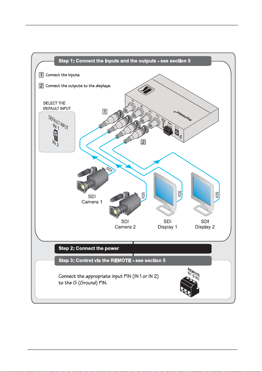
2.1 Quick Start
This quick start chart summarizes the basic setup and operation steps.
2
KRAMER: SIMPLE CREATIVE TECHNOLOGY
Page 5

Overview
3 Overview
The VS-211HDxl is a high-performance automatic standby switcher for
SD/HD-SDI and 3G HD-SDI video signals. The VS-211HDxl
automatically switches to the secondary input whenever the primary video
signal is interrupted. If the primary signal reappears, the unit automatically
switches back to the primary input.
In addition, the VS-211HDxl features:
• Maximum data rate of up to 2.97Gbps
• Multi-standard operation – SMPTE 259M, 292M and 424M
compliance and support for data rates of 270Mbps, 1483.5Mbps,
1485Mbps and 2970Mbps
• A DEFAULT INPUT switch for selecting the default SDI master
source signal
• Contact closure remote control for forced operation
• Active switching and has flexible sync detection and
reconstruction circuitry
To achieve the best performance:
1
• Use only good quality connection cables
to avoid interference,
deterioration in signal quality due to poor matching, and elevated
noise levels (often associated with low quality cables)
• Avoid interference from neighboring electrical appliances that
may adversely influence signal quality and position your Kramer
VS-211HDxl away from moisture, excessive sunlight and dust
1 Available from Kramer Electronics on our Web site at http://www.kramerelectronics.com
3
Page 6

Your VS-211HDxl 3G HD-SDI Automatic Standby Switcher
4 Your VS-211HDxl 3G HD-SDI Automatic Standby
Switcher
Figure 1 and Table 1 define the VS-211HDxl:
Figure 1: VS-211HDxl 3G HD-SDI Automatic Standby Switcher
Table 1: VS-211HDxl 3G HD-SDI Automatic Standby Switcher Features
# Feature Function
1 IN 1, IN 2 BNC Connectors Connect the SDI input sources 1 and 2
2 OUT 1, OUT 2 BNC Connectors Connect the SDI output acceptors 1 and 2
3 DEFAULT INPUT Switch Switch to select the default input (IN 1 or IN 2)
4 REMOTE IN 1 and IN 2 Terminal Block Connectors Connect to a contact closure switch
5
5V DC
6 INPUT SIGNAL 1,2 LEDs Illuminates when input is active
7 ON LED Illuminates when receiving power
+5V DC connector for powering the unit
4
KRAMER: SIMPLE CREATIVE TECHNOLOGY
Page 7

Using the VS-211HDxl
5 Using the VS-211HDxl
This section describes how to:
• Connect the VS-211HDxl (see section 5.1
• Select the default master source signal (see section 5.2
• Connect the REMOTE connector (see section 5.3
)
)
)
5.1 Connecting the VS-211HDxl 3G HD-SDI Automati
c Standby
Switcher
To connect the VS-211HDxl, as illustrated in the example in Figure 2
following
1
:
1. Connect SDI input source 1 (for example, SDI video cam era 1) to the IN 1
BNC connector.
2. Connect SDI input source 2 (for example, SDI video cam era 2) to the IN 2
BNC connector.
3. Connect SDI acceptor 1 (for example, SDI display 1) to the OUT 1 BNC
connector.
4. Connect SDI acceptor 2 (for example, SDI display 2) to the OUT 2 BNC
connector.
5. Set the DEFAULT INPUT switch to whichever input is the master input, as
described in section 5.2
.
6. If needed, connect remote switches to the REMOTE IN 1 and IN 2
terminal block connectors, as de s c r i b e d in s e c t i o n 5.3
.
7. Connect the 5V DC power adapter to the power socket and connect the
adapter to the mains electricity.
, do the
1 Switch OFF the power on each device before connecting it to your VS-211HDxl. After powering up your VS-211HDxl,
switch on the power on each device
5
Page 8

Using the VS-211HDxl
Figure 2: VS-211HDxl 3G HD-SDI Automatic Standby Switcher Connections
5.2 Selecting the Default Master Source Signal
When active input sources are connected to IN 1 and IN 2, the DEFAULT
INPUT switch setting determines the default master input source.
• If the master input signal is not detected, the VS-211HDxl
automatically activates the standby input
• If IN 1 is the default input and it fails, IN 2 activates
• If IN 2 is the default input and it fails, IN 1 activates
• If the master input reactivates while the standby input is active,
the unit automatically switches back to the master input
• If IN 2 is active while IN 1 is the default input and IN 1
reactivates, IN 1 reactivates
• If IN 1 is active while IN 2 is the default input and IN 2
reactivates, IN 2 reactivates
6
KRAMER: SIMPLE CREATIVE TECHNOLOGY
Page 9

Using the VS-211HDxl
5.3 Connecting the REMOTE Terminal Block Connector
Regardless of the default input switch setting, you can force the switching
of the active input by remote control. To do this, connect the appropriate
REMOTE input terminal block connector pins to a contact closure switch
(see Figure 3
).
• To force IN 1: connect REMOTE IN1 to PIN G (ground)
• To force IN 2: connect REMOTE IN2 to PIN G (ground)
Do not connect both the REMOTE IN1 and the REMOTE IN2
to PIN G simultaneously
Attach PIN IN1 to
PIN G to activate
INPUT 1
Figure 3: REMOTE Terminal Block Connector
Attach PIN IN2 to
PIN G to activate
INPUT 2
1
1 Note that the connection should be permanent, since the VS-211HDxl reverts to an automatic switcher when the connectio n
is removed
7
Page 10

Technical Specifications
6 Technical Specifications
Table 2 includes the technical specifications:
Table 2: Technical Specifications1 of the VS-211HDxl
INPUTS: 2 x 3G HD-SDI video on BNC connectors
OUTPUTS: 2 x 3G HD-SDI video on BNC connectors
MAX. OUTPUT LEVEL: 800mVpp /75Ω
DATA RATE: Up to 2.97Gbps
CONTROLS: Contact closure remote control, input default selection switch
COUPLING: AC
POWER SOURCE: 5V DC, 400mA
DIMENSIONS: 12cm x 7.2cm x 2.4cm (4.7" x 2.8" x 1.0") W, D, H
WEIGHT: 0.3kg (0.7lbs)
ACCESSORIES: Power supply, mounting bracket
OPTIONS: 19" rack adapter
1 Specifications are subject to change without notice
8
KRAMER: SIMPLE CREATIVE TECHNOLOGY
Page 11

LIMITED WARRANTY
Kramer El ec t ro ni cs (hereafter ) warrants t his product free from defec ts in material and workmanship under the
following terms.
HOW LONG IS THE WARRANTY
Labor and parts are warranted for seven years from the date of the first customer purchase.
WHO IS PROTECTED?
Only the first purchase customer may enforce this warranty.
WHAT IS COVERED AND WHA T IS NOT COVERED
Except as below, this warr anty covers all defects in ma terial or workmanship in th is product. The following are not covered
by the warranty:
1. Any product which is not distributed by Kramer, or whi ch is not purchased from an authorized Kramer dealer. If you are
uncertain as to whether a dealer is authorized, please contact Kramer at one of the agents listed in the Web site
www.kramerelectronics.com.
2. Any product, on which the serial number has been defaced, modified or removed, or on which the WARRANTY VOID
IF reattached, removed or otherwise interfered with.
TAMPERED sticker has been torn,
3. Damage, det erioratio n or ma lfunction resulti ng from:
i) Accident, m isuse, abu se, negle ct, fire, wat er, ligh tning or other acts of nature
ii) Produc t modi ficati on, or failu re to f ollow instru ctio ns sup plied with t he pro duct
iii) Repair o r att empte d repa ir by a nyon e not au thor ized by Kram er
iv) Any shipme nt of th e produ ct (c laims m ust be pres ented to the ca rrier )
v) Removal or insta llation of the pro duct
vi) Any other cause, w hich does n ot relate to a produ ct defe ct
vii) Cartons, equipment enclosures, cables or accessories used in conjunction with the product
WHAT WE WILL PA Y FOR AND WHAT WE WILL NOT PA Y FOR
We will pay labor and material expenses for covered i tems. W e will not pay for the following:
1. Removal or installations charges.
2. Costs of initial technical adjustments (set-up), including adjustment of user controls or programming. These costs are the
responsi bility o f the Kram er deal er from wh om the pr oduct w as purcha sed.
3. Shipping charges.
HOW YOU CAN GET WARRANTY SERVICE
1. To obtain service on you product, you must take or ship it prepaid to any authorized Kramer service center.
2. Whenever warranty service is required, the original dated invoice (or a copy) must be presented as proof of warranty
coverage, and should be included in any shipment of the product. Please also include in any mailing a contact name,
company, address, and a description of the problem(s).
3. For the name of the nearest Kramer authorized service center, consult your authorized dealer.
LIMITATION OF IMPLIED WARRANTIES
All implied warranties, including warranties of merchantability and fitness for a particular purpose, are limited in duration to
the length of this warranty.
EXCLUSION OF DAMAGES
The liability of Kramer for any effective products is limited to the repair or replacem ent of the product at our option. Kramer shall
not be liabl e for:
1. Damage to other property caused by defects in this product, damages based upon inconvenience, loss of use of the product, loss
of time, c omme rcial lo ss; or :
2. Any other dama ges, whet her i nci denta l, co nseq uenti al o r o therw ise. Som e co untri es ma y n ot a llow lim itati ons o n ho w lon g an
implied warranty lasts and/or do not allow the ex clusion or limitation of incidental or consequential damages, so the above
limitati ons and e xclusio ns may no t apply to you.
This warra nty give s you spec ific le gal rights , and you m ay also have othe r rights, w hich vary from p lace to pl ace.
NOTE:
All products returned t o Kramer for service must have prior approval. This may be obtained from your dealer.
This equipment has been tested to determine compliance with the requ irements of:
EN-50081: "Electrom agnetic compatibility (EMC);
Residential, commercial and light industry"
EN-50082: "Electrom agnetic compatibility (EMC) generic immunity st andard.
CFR-47: FCC* Rules and Regulations:
CAUTION!
generic emission standard.
Part 1:
Part 1: Residential, commercial and light industry environment".
Part 15: “Radio frequency devices
Subpart B Unintentional radiators”
Servicing the machines can only be done by an authorized Kramer technician. Any user who makes changes or
modifications to the unit without the expressed approval of the manufactu rer will void user aut hority to operate the
equipment.
Use the supplied DC power supply to feed power to the machine.
Please use recommended interconnection cables to connect the machine to o ther components.
* FCC and CE approved u sing STP cable (for twisted pai r products )
Kramer
9
Page 12

For the latest information on our products and a list of Kramer
distributors, visit our Web site: www.kramerelectronics.com,
where updat
es to this user manual may be found.
We welcome your questions, comments and feedback.
Safety Warning:
Disconnect the unit from the power supply before
opening/servicing.
Caution
Kramer Electronics, Ltd.
Web site: www.kramerelectronics.com
E-mail: info@kramerel.com
P/N: 2900-000499 REV 2
 Loading...