


 Loading...
KRAMER ELECTRONICS LTD.
USER MANUAL
MODEL:
VP-728
Presentation Switcher/Scaler
P/N: 2900-000363 Rev 9
Contents
1 |
Introduction |
1 |
2 |
Getting Started |
2 |
2.1 |
Achieving the Best Performance |
2 |
2.2 |
Recycling Kramer Products |
2 |
3 |
Overview |
3 |
3.1 |
Defining the VP-728 Presentation Switcher/Scaler |
5 |
4 |
Installing in a Rack |
9 |
5 |
Connecting the VP-728 |
10 |
5.1 |
Connecting a PC |
13 |
6 |
Presentation Switcher / Scaler Buttons |
14 |
6.1 |
Switching an Input |
14 |
6.2 |
The PIP Button Feature |
15 |
6.3 |
Locking and Unlocking the Front Panel |
19 |
6.4 |
The Infrared Remote Control Transmitter |
20 |
7 |
Configuring the VP-728 via the OSD MENU Screens |
21 |
7.1 |
The Input Screen |
22 |
7.2 |
The Picture Screen |
24 |
7.3 |
The Output Screen |
25 |
7.4 |
The PIP Screen |
27 |
7.5 |
The Audio Screen |
28 |
7.6 |
The Geometry Screen |
29 |
7.7 |
The Setup Screen |
30 |
7.8 |
The Advanced Setup Screen |
32 |
7.9 |
The Info Screen |
37 |
8 |
Using Text Overlay |
38 |
9 |
Audio Flash Memory Upgrade |
40 |
9.1 |
Downloading from the Internet |
40 |
9.2 |
Connecting the PC to the RS-232 Port |
41 |
9.3 |
Upgrading the Audio Firmware |
41 |
10 |
Technical Specifications |
46 |
11 |
VP-728 Communication Protocol |
51 |
11.1 |
Error Codes Description |
62 |
VP-728 – Contents |
i |
Figures
Figure 1: VP-728 Presentation Switcher/Scaler Front Panel |
6 |
Figure 2: VP-728 Presentation Switcher/Scaler Rear Panel |
8 |
Figure 3: Connecting to the VP-728 Rear Panel |
12 |
Figure 4: Crossed Cable RS-232 Connection |
13 |
Figure 5: Straight Cable RS-232 Connection with a Null Modem Adapter |
13 |
Figure 6: PIP Source over Background |
16 |
Figure 7: The SWAP Status |
17 |
Figure 8: IR Remote Control Transmitter |
20 |
Figure 9: MENU Items |
21 |
Figure 10: Input Screen |
22 |
Figure 11: Picture Screen |
24 |
Figure 12: Output Screen |
25 |
Figure 13: PIP Screen |
27 |
Figure 14: Audio Screen |
28 |
Figure 15: Geometry Screen |
29 |
Figure 16: Setup Screen |
30 |
Figure 17: Advanced Setup Screen |
32 |
Figure 18: Misc Screen |
33 |
Figure 19: Input Functions |
35 |
Figure 20: Output Functions |
36 |
Figure 21: Active Video Functions |
37 |
Figure 22: Information Screen |
37 |
Figure 23: Text Overlay Application Screen |
38 |
Figure 24: Splash Screen |
41 |
Figure 25: Atmel – Flip Window |
42 |
Figure 26: Device Selection Window |
42 |
Figure 27: Selecting the Device Window |
43 |
Figure 28: Loading the Hex |
43 |
Figure 29: RS-232 Window |
44 |
Figure 30: Atmel – Flip Window (Connected) |
44 |
Figure 31: Atmel – Flip Window (Operation Completed) |
45 |
ii |
VP-728 - Contents |

1 Introduction
Welcome to Kramer Electronics! Since 1981, Kramer Electronics has been providing a world of unique, creative, and affordable solutions to the vast range of problems that confront the video, audio, presentation, and broadcasting professional on a daily basis. In recent years, we have redesigned and upgraded most of our line, making the best even better!
Our 1,000-plus different models now appear in 11 groups that are clearly defined by function: GROUP 1: Distribution Amplifiers; GROUP 2: Switchers and Routers; GROUP 3: Control Systems; GROUP 4: Format/Standards Converters; GROUP 5: Range Extenders and Repeaters; GROUP 6: Specialty AV Products; GROUP 7: Scan Converters and Scalers; GROUP 8: Cables and Connectors; GROUP 9: Room Connectivity; GROUP 10: Accessories and Rack Adapters and GROUP 11: Sierra Products.
Congratulations on purchasing your Kramer VP-728 Presentation Switcher / Scaler, which is ideal for the following typical applications:
•Projection systems in conference rooms, boardrooms, auditoriums, hotels and churches, production studios, rental and staging
•Any application where high quality conversion and switching of multiple and different video signals to graphical data signals is required for projection purposes
VP-728 – Introduction |
1 |

2 Getting Started
We recommend that you:
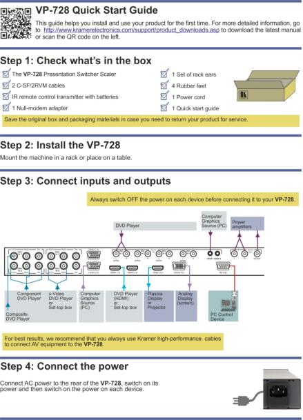
•Unpack the equipment carefully and save the original box and packaging materials for possible future shipment
•Review the contents of this user manual
•Use Kramer high performance high resolution cables
•Use only the power cord that is supplied with this machine
Go to http://www.kramerelectronics.com to check for up-to-date user i manuals, application programs, and to check if firmware upgrades
are available (where appropriate).
2.1Achieving the Best Performance
To achieve the best performance:
•Use only good quality connection cables to avoid interference, deterioration in signal quality due to poor matching, and elevated noise levels (often associated with low quality cables)
•Do not secure the cables in tight bundles or roll the slack into tight coils
•Avoid interference from neighboring electrical appliances that may adversely influence signal quality
•Position your Kramer VP-728 away from moisture, excessive sunlight and dust
2.2Recycling Kramer Products
The Waste Electrical and Electronic Equipment (WEEE) Directive 2002/96/EC aims to reduce the amount of WEEE sent for disposal to landfill or incineration by requiring it to be collected and recycled. To comply with the WEEE Directive, Kramer Electronics has made arrangements with the European Advanced Recycling Network (EARN) and will cover any costs of treatment, recycling and recovery of waste Kramer Electronics branded equipment on arrival at the EARN facility. For details of Kramer’s recycling arrangements in your particular country go to our recycling pages at http://www.kramerelectronics.com/support/recycling/.
2 |
VP-728 - Getting Started |

3 Overview
The Kramer VP-728 is a 9-input Proscale™ Presentation Switcher / Scaler with unbalanced stereo and digital S/PDIF audio. The VP-728 scales any composite, s-Video (Y/C), component video (YUV), HDMI or computer graphics video signal, as well as JPEG files (via USB) up or down to a selectable graphics or HDTV output resolution. It also provides glitch-free switching between sources through FTB™ (fade-thru-black) switching technology, in which the video fades to black and then the new input fades from black for glitch-free and smooth switching. The output signal provides constant sync so the display never glitches. The output signal is available simultaneously on a 15-pin HD computer graphics video (UXGA) connector and on an HDMI connector.
The VP-728 features include:
•Silicon Optix HQV® Video Processing - HQV (Hollywood Quality Video) processing represents the state-of-the-art in video processing technology, with the highest quality de-interlacing, noise reduction, and scaling performance for both standard-definition and high-definition signals
•K-IIT XL™ Picture-in-Picture Image Insertion Technology - ultra stable picture- in-picture, picture-and-picture, and split screen capability. Any video source can be inserted into or positioned next to a computer graphics video source or vice versa with window positioning and sizing controls
•Four user definable (universal) video inputs (each can be set as composite video, s-Video (Y/C) or component video), two computer graphics video inputs, two HDMI inputs and 1 USB input (for reading JPEG picture files that are recognized up to 2048x1536 and do not exceed 1MB)
•HDTV compatible component input
•HDTV output resolutions - 720p 1080i, and 1080p
•Scaled video outputs - HDMI and computer graphics video
•HDMI support of up to 2.25Gbps bandwidth per graphic channel
Suitable for resolutions up to UXGA at 60Hz, and for all HD resolutions
•Multiple computer graphics output resolutions - including a user-defined output resolution with selectable refresh rates
VP-728 – Overview |
3 |
•Multiple aspect ratio selections
•Companion AFV (audio-follow-video) for every analog video input
•Embedded audio on the two HDMI inputs and output
The embedded audio feature is not available for the RGB resolutions 1920x1200 and 1920x1080. (It is available for 1080p)
•Built-in noise reduction and picture enhancement features
•Audio inputs - four (stereo audio or S/PDIF on two RCA connectors) for each of the four universal video inputs; two unbalanced stereo audio (on 3.5mm mini jacks) for the two computer graphics video inputs; and embedded audio on the HDMI inputs
•Audio outputs - S/PDIF and unbalanced stereo audio (RCA connectors). The machine transcodes stereo or S/PDIF audio to both stereo and S/PDIF audio and embeds audio into the HDMI output
Tip: To use a 5.1 digital audio source, connect this HDMI or S/PDIF source (for example, a Blu-ray player) directly to your receiver or display
•Built-in Time Base Corrector - stabilizes video sources with unstable sync
•Built-in video Proc-Amp - color, hue, sharpness, contrast, and brightness are set individually for each input
•A BLANK button, a FREEZE button, a RESET TO XGA/720P button (to hardware-reset the output resolution); and a PANEL LOCK button
The front panel blank, freeze and lock buttons can be programmed via the OSD menu (see Page 34)
•Built-in audio Proc-Amp with bass, treble, balance and loudness control, as well as audio delay
•Firmware upgrade performed via the USB port
•Slideshow option, letting you run a slideshow via the USB port
•An OSD (On-Screen Display) – for making adjustments – that can be located anywhere on the screen
4 |
VP-728 - Overview |
In addition, the VP-728:
•Includes non-volatile memory that retains the last settings, after switching the power off and then on again
•Digitally reprocesses the signal to correct mastering errors and regenerates the video at a higher line and pixel rate format, providing native-resolution video for LCD, DLP and plasma displays
•Is specifically designed to improve video quality by reducing chroma noise
•Scales and zooms (to up to 400% of the original size)
•Can provide non-linear scaling for 4:3 and 16:9 transformation
Control your VP-728 directly via the front panel push buttons, or:
•By RS-232 serial commands transmitted by a touch screen system, PC, or other serial controller
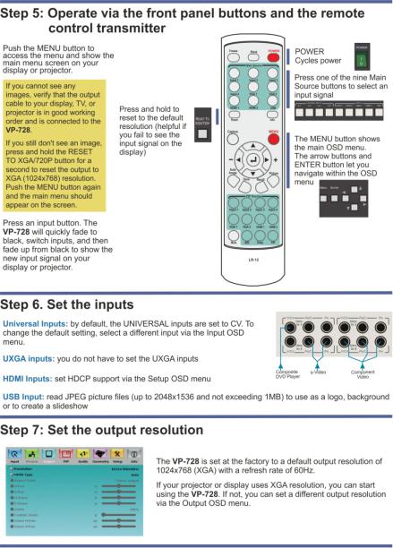
•Remotely, from the infrared remote control transmitter (with on-screen menus)
The VP-728 is housed in a 19” 1U rack mountable enclosure, with rack “ears” included and is fed from a 100-240 VAC universal switching power supply.
3.1Defining the VP-728 Presentation Switcher/Scaler
This section defines the VP-728.
VP-728 – Overview |
5 |
6
Overview – 728 VP -
Figure 1: VP-728 Presentation Switcher/Scaler Front Panel
# |
Feature |
|
|
Function |
|
1 |
POWER Switch |
|
|
Illuminated switch for turning the machine ON or OFF |
|
2 |
IR Receiver / LED |
|
|
Lights red when the unit accepts IR remote commands |
|
3 |
UNIVERSAL INPUT |
|
Press to select the composite video / s-Video / component video source and the appropriate audio source |
||
|
Selector Buttons |
|
|
(from 1 to 4) |
|
4 |
|
UXGA 1 |
|
Press to select the UXGA source 1 and the appropriate audio source |
|
5 |
INPUT Selector |
UXGA 2 |
|
Press to select the UXGA source 2 and the appropriate audio source |
|
6 |
Buttons |
HDMI 1 |
|
Press to select the HDMI source 1 |
|
7 |
(illuminates |
HDMI 2 |
|
Press to select the HDMI source 2 |
|
|
when selected) |
|
|
|
|
8 |
USB |
|
Press to select the USB source (JPEG files on a USB memory stick) and also run/stop the slideshow (see |
||
|
|
||||
|
|
|
|
Section 7.7.1) |
|
|
|
|
|
|
|
9 |
PIP Button |
|
|
Toggles the picture-in-picture function (see Section 6.2) |
|
10 |
BLANK Button |
|
|
Press to toggle between a blank screen (blue or black) and the display. |
|
|
|
|
|
The BLANK button can be programmed to mute the audio signal at the same time (see Page 34) |
|
11 |
FREEZE Button |
|
|
Press to freeze/unfreeze the output video image, as well as pause the slideshow (see Page 31). |
|
|
|
|
|
The FREEZE button can be programmed to mute the audio signal at the same time (see Page 34) |
|
12 |
MENU Button |
|
|
Press to display the OSD menu screen. Press again to return to normal operation. |
|
13 |
ENTER Button |
|
|
Press to move to the next level in the OSD screen or to accept a new parameter |
|
14 |
Button |
|
|
Decreases the range by one step in the OSD screen or moves to the previous level in the OSD screen. |
|
|
|
|
|
Decreases the volume level, when not in the OSD menu |
|

Overview – 728 VP -
7
# |
Feature |
Function |
||
15 |
Button |
Moves up one step (in the same level) in the OSD screen, or moves to the previous slide when running a |
||
|
slideshow (see Section 7.7.1) |
|||
|
|
|||
|
|
|
|
|
16 |
Button |
Increases the range by one step in the OSD screen |
||
|
|
Increases the volume level, when not in the OSD menu |
||
17 |
Button |
Moves down one step (in the same level) in the OSD screen, or moves to the next slide when running a |
||
|
slideshow (see Section 7.7.1) |
|||
|
|
|||
|
|
|
|
|
18 |
RESET TO XGA/720p |
Press and hold to reset to the default resolution (toggles between RESET TO XGA and 720p) |
||
|
Button |
|
|
|
19 |
PANEL LOCK Button |
Press to lock/unlock the front panel to prevent unintentional operation |
||
20 |
USB Connector |
Connects to a USB drive to read JPEG files (smaller than 1MB and up to a resolution of 2048x1536) and |
||
|
|
also to download new firmware |
||
8
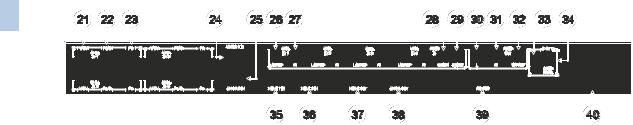
Figure 2: VP-728 Presentation Switcher/Scaler Rear Panel
|
# |
Feature |
|
|
Function |
|
21 |
UNIV. IN RCA Connectors |
Y/CV |
Connects to the video acceptor which can be either composite video (Y/CV), s-Video (Y/CV, |
|
|
22 |
PB/C |
|||
|
(from 1 to 4) |
|
PB/C ) or component video (Y/CV, PB/C, PR) |
||
|
23 |
|
PR |
||
|
|
|
|
||
|
24 |
UXGA 1 IN 15-pin HD Connector |
|
Connects to the UXGA (analog interface) graphics source 1 |
|
|
25 |
UXGA 2 IN 15-pin HD Connector |
|
Connects to the UXGA (analog interface) graphics source 2 |
|
|
26 |
AUDIO IN UNIV. IN RCA |
L/S/PDIF |
Connects to the left unbalanced stereo analog audio source. Alternatively, connect to a digital |
|
|
|
Connectors (from 1 to 4) |
|
audio source |
|
|
27 |
|
|
R |
Connects to the right unbalanced stereo analog audio source |
|
28 |
AUDIO IN 3.5 Mini Jack |
UXGA 1 |
Connects to the unbalanced stereo analog audio source 1 |
|
|
29 |
|
|
UXGA 2 |
Connects to the unbalanced stereo analog audio source 2 |
|
30 |
AUDIO OUT RCA Connectors |
L |
Connects to the left channel of the unbalanced stereo analog audio acceptor |
|
|
31 |
|
|
R |
Connects to the right channel of the unbalanced stereo analog audio acceptor |
|
32 |
|
|
S/PDIF |
Connects to a digital audio acceptor |
- |
33 |
AUDIO PROG |
Program Button |
Push to upgrade to the latest Kramer audio firmware. Release for normal operation |
|
34 |
|
Terminal Block Connector |
Connects to a PC for audio firmware upgrade |
||
VP |
|
||||
35 |
HDMI 1 IN Connector |
|
Connects to the HDMI 1 source |
||
– 728 |
36 |
HDMI 2 IN Connector |
|
Connects to the HDMI 2 source |
|
37 |
HDMI OUT Connector |
|
Connects to the HDMI acceptor |
||
Overview |
|
|
|
|
|
39 |
RS-232 9-pin D-sub Connector |
|
Connects to a PC or serial controller |
||
|
38 |
UXGA OUT 15-pin HD Connector |
|
Connects to the video acceptor that displays the scaled output. |
|
|
|
|
|
|
In the default HDTV mode, the signal is transmitted via 3 pins: PIN 1 is Pr, PIN 2 is Y, PIN 3 Pb |
|
|
|
|
|
|
|
40 |
Power Connector with Fuse |
|
AC connector for connecting power to the unit |
|

4 Installing in a Rack
This section provides instructions for rack mounting the unit.
VP-728 - Installing in a Rack |
9 |

5 |
Connecting the VP-728 |
|
|
i |
Always switch off the power to each device before connecting it to your |
|
VP-728. After connecting your VP-728, connect its power and then |
|
switch on the power to each device.
To connect the VP-728 as illustrated in the example in Figure 3, do the following:
1.Connect the video sources:
A component video source (for example, a DVD player) to the UNIV. IN 1 RCA connectors, Y/CV, PB/C and PR
Component video is sometimes called YUV, or Y, B-Y, R-Y
An s-Video source (for example, a DVD player) to the UNIV. IN 4 RCA connectors, Y/CV and PB/C
A computer graphics source to the UXGA 1 IN 15-pin HD computer graphics video connector
An HDMI source (for example, a DVD player) to the HDMI 1 IN connector
A graphics data source (for example, JPEG files that should be smaller than 1MB and should not exceed a resolution of 2048x1536, from a PC or a USB flash drive) to the USB connector on the front panel of the machine
2.Connect the unbalanced stereo or digital audio sources:
The audio of the component video source 1 to the AUDIO UNIV IN 1 S/PDIF RCA connector
The audio of the s-Video source 4 to the AUDIO UNIV IN 4 L and R RCA connector
The audio of computer graphics source to the AUDIO UXGA 1 3.5mm mini jack
Although this connecting example shows only several inputs that are connected, you can connect all the inputs simultaneously
10 |
VP-728 - Connecting the VP-728 |

3.Connect the video outputs:
The HDMI OUT connector to an HDMI acceptor (for example, a plasma display)
The UXGA OUT 15-pin HD computer graphics video connector to a video acceptor (for example, an analog display)
In the HDTV mode, the signal goes out via three PINS: PIN 1 is Red or Pr, PIN 2 is Green or Y, PIN 3 is Blue or Pb
4.Connect the AUDIO OUT L and R unbalanced stereo audio output and/or the S/PDIF digital audio output to audio acceptors, for example, power amplifiers.
5.Connect the power cord.
We recommend that you use only the power cord that is supplied with this machine
6.If required, connect a PC via RS-232, (see Page 13).
iThe USB connector, audio sources and acceptors, and power cord are not shown in Figure 3.
VP-728 - Connecting the VP-728 |
11 |
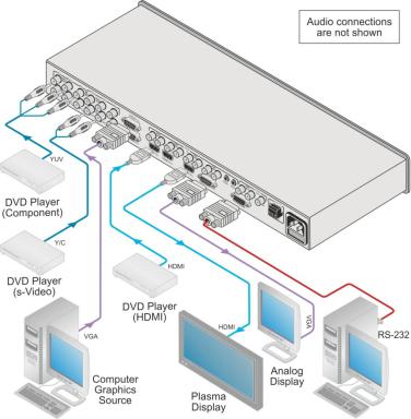
Figure 3: Connecting to the VP-728 Rear Panel
12 |
VP-728 - Connecting the VP-728 |

5.1Connecting a PC
You can connect to the unit via a crossed RS-232 connection, using for example, a PC. A crossed cable or null-modem is required as shown in method A and B respectively. If a shielded cable is used, connect the shield to pin 5.
Method A (Figure 4)—Connect the RS-232 9-pin D-sub port on the unit via a crossed cable (only pin 2 to pin 3, pin 3 to pin 2, and pin 5 to pin 5 need be connected) to the RS-232 9-pin D-sub port on the PC.
Note: There is no need to connect any other pins.
9 |
5 |
9 |
5 |
|
4 |
4 |
|
||
8 |
3 |
8 |
3 |
PC |
7 |
7 |
|||
6 |
2 |
6 |
2 |
|
1 |
1 |
|
||
|
|
|
Figure 4: Crossed Cable RS-232 Connection
Hardware flow control is not required for this unit. In the rare case where a controller requires hardware flow control, short pin 1 to 7 and 8, and pin 4 to 6 on the controller side.
Method B (Figure 5)—Connect the RS-232 9-pin D-sub port on the unit via a straight (flat) cable to the null-modem adapter, and connect the null-modem adapter to the RS-232 9-pin D-sub port on the PC. The straight cable usually contains all nine wires for a full connection of the D-sub connector. Because the null-modem adapter (which already includes the flow control jumpering described in Method A above) only requires pins 2, 3 and 5 to be connected, you are free to decide whether to connect only these 3 pins or all 9 pins.
9 |
5 |
Null-Modem |
8 |
4 |
|
7 |
3 |
Adapter |
2 |
||
6 |
1 |
|
|
|
to PC
Figure 5: Straight Cable RS-232 Connection with a Null Modem Adapter
VP-728 - Connecting the VP-728 |
13 |

6 Presentation Switcher / Scaler Buttons
The VP-728 includes the following front panel buttons:
•Nine INPUT selector buttons
•A PIP button
•BLANK and FREEZE buttons
•Six OSD buttons
•A RESET TO XGA/720p button
•A PANEL LOCK button
6.1Switching an Input
Each INPUT SELECTOR button can be used to select the source. When selected, the button illuminates.
You can switch seamlessly between each input that is connected to a source by pressing the appropriate INPUT SELECTOR button.
SEAMLESS SWITCHING - FTB™ switching for glitchless transitions between inputs
14 |
VP-728 - Presentation Switcher / Scaler Buttons |

6.2The PIP Button Feature
The Picture-in-Picture inserter (PIP) uses K-IIT XL™ image insertion technology to present video and graphic sources simultaneously so that you can display:
•An inserted video source PIP over a graphic source background
•An inserted graphic source PIP over a video source background
VIDEO SOURCE – can be composite or s-Video GRAPHIC SOURCE – can be HDMI, UXGA or component
For example, you can show a live video window on top of a graphic background and vice versa.
If the HDMI signal is HDCP protected, it cannot appear on a display that is not HDCP compliant and the machine will not output a picture on the VGA output
The VP-728 supports three PIP modes:
•Picture-in-Picture, with a smaller window superimposed over a full screen image
•Picture + Picture, where both images are placed side-by-side with the same height
•Split, where both images appear side-by-side and the aspect ratios of both images are maintained
6.2.1Activating the PIP Feature
Activate the PIP feature in any of the following ways:
•Press and hold the PIP front panel button while pressing the input button of the required PIP source
•Press the PIP key on the IR remote control transmitter (see Section 6.4)
•Access the OSD PIP menu (see Figure 13) and selecting PIP On
VP-728 - Presentation Switcher / Scaler Buttons |
15 |
6.2.2Selecting the PIP Source
To easily select the PIP source, press and hold the PIP front panel button while pressing the input button of the required PIP source.
For example, to select UXGA 2 as the graphic PIP source over a video background, press the PIP front panel button while pressing the UXGA 2 front panel button.
To select the PIP source using the IR remote controller, press the desired PIP source on the remote controller.
For example, if you want to select HDMI 2 as the PIP source, press the HDMI 2 button in the PIP source area on the IR remote controller.
To set the PIP source via the OSD menu, do the following:
1.Press the MENU button to enter the OSD menu.
2.Press the  button to move to the PIP icon.
3.Scroll down to select Source and press ENTER.
4.Use the  or
or  buttons to select the PIP Source from the drop-down list box, and press ENTER (see Figure 13).
5.To exit the OSD menu, press the MENU button.
Figure 6: PIP Source over Background
16 |
VP-728 - Presentation Switcher / Scaler Buttons |
Loading...