


 Loading...
Kramer Electronics, Ltd.
USER MANUAL
Model:
VS-1616D
16x16 Digital Matrix Switcher

Contents
Contents
1 |
Introduction |
1 |
2 |
Getting Started |
2 |
2.1 |
Quick Start |
2 |
3 |
Overview |
4 |
3.1 |
Recommendations for Best Performance |
5 |
3.2 |
Safety Instructions |
5 |
3.1 |
Shielded Twisted Pair/Unshielded Twisted Pair |
5 |
3.2 |
About the Power Connect™ Feature |
6 |
3.3 |
Recycling Kramer Products |
6 |
4 |
Defining the VS-1616D 16x16 Digital Matrix Switcher |
6 |
4.1 |
Using the IR Transmitter |
10 |
5 |
Installing the VS-1616D in a Rack |
11 |
6 |
Connecting the VS-1616D 16x16 Digital Matrix Switcher |
12 |
6.1 |
Port Numbering |
13 |
6.1.1 |
EDID Numbering Examples |
14 |
6.2 |
Serial Data Flow on DGKat Plus RS-232 Cards |
14 |
6.3 |
Audio Mode Selection on HDMI plus Audio Cards |
15 |
6.4 |
Connecting to the VS-1616D via RS-232 |
15 |
6.5 |
Connecting to the VS-1616D via Ethernet |
16 |
6.5.1 |
Connecting the Ethernet Port directly to a PC |
16 |
6.5.2 |
Connecting to the Ethernet Port via a Network Switch/Hub |
18 |
7 |
Operating Your Video Matrix Switcher |
19 |
7.1 |
Startup Display |
19 |
7.1.1 |
Viewing the Display |
20 |
7.2 |
Using the Selector Buttons |
20 |
7.3 |
Confirming Actions |
20 |
7.3.1 |
Toggling between the At Once and Confirm Modes |
21 |
7.3.2 |
Confirming a Switching Action |
21 |
7.4 |
Switching Actions |
21 |
7.4.1 |
Switching one Input to one Output |
22 |
7.4.2 |
Switching Several Inputs to Several Outputs |
22 |
7.4.3 |
Turning an Output Off |
23 |
7.4.4 |
Turning Off Several Outputs |
23 |
7.4.5 |
Recalling the Default Setup |
23 |
7.5 |
Locking the Front Panel Buttons |
24 |
8 |
Using the Configuration Menus |
24 |
8.1 |
Using the Setup Menu |
26 |
8.1.1 |
Setup Menu—1: inXX=>ALL, Switching one Input to all Outputs |
26 |
8.1.2 |
Setup Menu—3: outXX=>OFF, Turning an Output Off |
26 |
8.1.3 |
Setup Menu—7: EDID, Assignment to an Input |
27 |
i

Contents
8.1.4 |
Setup Menu—9: Delay, Setting for an Output |
28 |
8.1.5 |
Setup Menu—4: store setup XX, Storing the Setup in a Preset |
28 |
8.1.6 |
Setup Menu—6: recall setup XX, Recalling a Preset |
29 |
8.2 |
Using the Config Menu |
29 |
8.2.1 |
Config Menu—Input Signal Detection Display |
30 |
8.2.2 |
Config Menu—Input Port Parameter Setting |
31 |
8.2.3 |
Config Menu—Output Load Detection Display |
33 |
8.2.4 |
Config Menu—Output Port Parameter Setting |
34 |
8.2.5 |
Config Menu—Interface Configuration |
36 |
8.2.6 |
Config Menu—Interface Reply Configuration |
36 |
8.2.7 |
Config Menu—Protocol Switching |
37 |
8.2.8 |
Config Menu—Store Default Setup |
37 |
8.2.9 |
Config Menu—Total Matrix Reset |
38 |
8.2.10 |
Config Menu—Display Firmware Versions |
39 |
9 |
Configuring the Number of Installed Input and Output Ports |
39 |
10 |
Installing and Using the Test Module to Troubleshoot Video Problems 40 |
|
10.1 |
Installing the Test Module |
40 |
10.2 |
Setting the Resolution of the Generated Video |
40 |
10.3 |
Setting the Pattern of the Generated Video |
41 |
10.4 |
Using the Test Module to Troubleshoot Video Problems |
41 |
10.4.1 |
Testing the Projector Output |
42 |
10.4.2 |
Testing the Output Signal Path to the Projector |
42 |
10.4.3 |
Testing the Input and Output Signal Path to the Projector |
43 |
11 |
I/O Card Hardware Installation Instructions |
43 |
12 |
Upgrading the VS-1616D Firmware |
44 |
13 |
Technical Specifications |
45 |
14 |
Default Communication Parameters |
47 |
15 |
Factory Default EDID |
47 |
15.1 |
DVI Input Card |
47 |
15.2 |
HDCP Input Card |
48 |
15.3 |
HDMI Input Card |
50 |
15.4 |
HDMI plus Audio Input Card |
52 |
15.5 |
DVI Dual Channel Input Card |
53 |
15.6 |
DGKat Input Card |
55 |
15.7 |
HDBaseT Input Card |
57 |
15.8 |
VGA Input Card |
59 |
16 |
Communication Protocols |
60 |
16.1 |
Protocol 3000 |
60 |
16.1.1 |
Kramer Protocol 3000 Syntax |
60 |
16.1.2 |
Device Message Format |
60 |
16.1.3 |
Command Terms |
61 |
16.1.4 |
Entering Commands |
61 |
16.1.5 |
Command Forms |
62 |
ii
KRAMER: SIMPLE CREATIVE TECHNOLOGY

Contents
16.1.6 |
Chaining Commands |
62 |
16.1.7 |
Maximum String Length |
62 |
16.1.8 |
Table of Protocol 3000 Commands |
62 |
16.2 |
Protocol 2000 |
63 |
Figures
Figure 1: VS-1616D 16x16 Digital Matrix Switcher Front Panel |
7 |
Figure 2: VS-1616D Front Panel Numeric Keypad |
8 |
Figure 3: VS-1616D 16x16 Digital Matrix Switcher Rear Panel Showing DVI cards |
9 |
Figure 4: Connecting the VS-1616D |
12 |
Figure 5: Sample Port Numbering |
13 |
Figure 6: EDID Numbering Assignment |
14 |
Figure 7: DGKat Card Serial Data Transmission |
15 |
Figure 8: Audio Mode Selection on HDMI plus Audio Cards |
15 |
Figure 9: Local Area Connection Properties Window |
17 |
Figure 10: Internet Protocol (TCP/IP) Properties Window |
18 |
Figure 11: Default Startup Status Display Sequence |
19 |
Figure 12: Menu Tree |
25 |
Figure 13: Resolution DIP-switch |
41 |
Figure 14: Signal Paths for Isolating problems |
42 |
Figure 15: Inserting the Card into a Slot |
43 |
Figure 16: Card Handles |
44 |
Tables
Table 1: VS-1616D |
16x16 Digital Matrix Switcher Front Panel Features |
8 |
Table 2: VS-1616D |
Front Panel Numeric Keypad Labels |
8 |
Table 3: VS-1616D |
16x16 Digital Matrix Switcher Rear Panel Features |
10 |
Table 4: Port Numbering |
13 |
|
Table 5: EDID Configuration Requests and Results |
14 |
|
Table 6: Audio Mode DIP-switch Operation |
15 |
|
Table 7: Available PC Resolutions for Generated Video (Jumper off) |
41 |
|
Table 8: Available HD Resolutions for Generated Video (Jumper on, default) |
41 |
|
Table 9: Technical Specifications of the 16x16 Digital Matrix Switcher |
45 |
|
Table 10: Technical Specifications of VS-1616D Compatible Cards |
46 |
|
Table 11: Default Communication Parameters for the VS-1616D |
47 |
|
Table 12: Hex Table (IN 1-16 to OUT 1-16) |
63 |
|
iii

Introduction
1 Introduction
Welcome to Kramer Electronics! Since 1981, Kramer Electronics has been providing a world of unique, creative, and affordable solutions to the vast range of problems that confront the video, audio, presentation, and broadcasting professional on a daily basis. In recent years, we have redesigned and upgraded most of our line, making the best even better! Our 1,000-plus different models now appear in 11 groups1 that are clearly defined by function.
Congratulations on purchasing your Kramer VS-1616D 16x16 Digital Matrix Switcher. This product is ideal for the following typical applications:
•Professional display systems requiring video signal routing
•Broadcast, presentation and production facilities, as well as monitoring in large duplication systems
•Rental/staging applications
The package includes the following items:
•VS-1616D 16x16 Digital Matrix Switcher
•Power cord
•Kramer RC-IR3 infrared remote control transmitter (including the required batteries and a separate user manual2)
•This user manual2
Note: Throughout this user manual the chassis configuration is shown with 16 DVI inputs and 16 DVI outputs as a representation only. The following cards are available and may be mixed in the same chassis:
•DVI
•DVI dual link
•DVI (HDCP)
•DVI (over 4LC fiber optic cable)
•DVI (over fiber optic cable) with 670 module (HDCP)
•HDMI (HDCP)
•HDMI plus analog audio (HDCP)
•HDMI plus digital audio (HDCP)
•HDMI plus RS-232 (HDCP)
•HDBaseT plus IR and RS-232 plus Ethernet
•VGA
1 GROUP 1: Distribution Amplifiers; GROUP 2: Switchers and Routers; GROUP 3: Control Systems; GROUP 4: Format/Standards Converters; GROUP 5: Range Extenders and Repeaters; GROUP 6: Specialty AV Products; GROUP 7: Scan Converters and Scalers; GROUP 8: Cables and Connectors; GROUP 9: Room Connectivity; GROUP 10: Accessories and Rack Adapters; GROUP 11: Sierra Products
2 Download up-to-date Kramer user manuals from http://www.kramerelectronics.com
1

Getting Started
2 Getting Started
We recommend that you:
•Unpack the equipment carefully and save the original box and packaging materials for possible future shipment
•Review the contents of this user manual
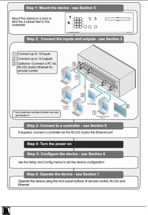
2.1Quick Start
The following quick start chart summarizes the basic setup and operation steps.
2 |
KRAMER: SIMPLE CREATIVE TECHNOLOGY |
Getting Started
3

Overview
3 Overview
The Kramer VS-1616D is a high performance matrix switcher chassis that supports up to 16 x 16 ports1 for various signals (depending on the type of cards installed). It features a very high bandwidth2 of up to 3.2Gbps (for the chassis only, effective bandwidth of the system depends on the I/O cards) that ensures transparent performance even in the most critical applications. The cards re-clock and equalize the signals and the chassis can route any or all inputs to any or all outputs simultaneously.
The VS-1616D is highly configurable–you can add or remove inputs and outputs independently in groups of two and mix different types of input/ouput cards in the same chassis. For example, you can configure a device as a 4 x 12 or a 16 x 8 matrix switcher to exactly suit your needs.
The VS-1616D features:
•Full 16 x 16 non-blocking matrix array to switch any of the 16 input digital signals to any or all outputs (see Section 6)
•Easy access to 59 preset memory locations for quick access to user-defined setups
•The Kramer 2000 Protocol for serial control
•A 40 character by 2 line LCD that shows the operational status or the configuration menu
•A lock function to prevent tampering with the front panel
•A default EDID (Extended Display Identification Data) for each input
•I-EDIDPro™ Kramer Intelligent EDID Processing™ – Intelligent EDID handling and processing algorithm ensures plug and play operation for DVI systems
•Non-volatile EDID storage
•Kramer Core™—flexible infrastructure conversion. Copper, fiber or Twisted Pair, all can be used at the same time according to input/output module selection. The matrix receives signals from compatible Kramer transmitters, automatically converts between available infrastructure options and sends the signals to compatible Kramer receivers
•Equalization and re-clocking on all card types
You can operate the VS-1616D via the front panel buttons3 or remotely via:
•RS-232 serial commands transmitted by a touch screen system, PC or other serial controller
1 Can also be configured for other sizes (up to a maximum of 16 x 16)
2 For maximum bandwidth supported by each type of card see the Technical Specifications in Section 13
3 The VS-1616D is a sophisticated device but has been designed to be as simple as possible to operate. Due to space limitations on the front panel 32 input/output selector buttons are instead substituted by a keypad. For details of how to route inputs to outputs, see Section 7.2
4 |
KRAMER: SIMPLE CREATIVE TECHNOLOGY |

Overview
•Ethernet over a LAN
•The infrared remote control transmitter
The VS-1616D is housed in a 19" rack-mountable enclosure.
To achieve the best performance:
•Connect only good quality connection cables, thus avoiding interference, deterioration in signal quality due to poor matching, and elevated noise levels (often associated with low quality cables)
•Avoid interference from neighboring electrical appliances that may adversely influence signal quality and position your Kramer VS-1616D in a location free from moisture and away from excessive sunlight and dust
3.1Recommendations for Best Performance
To achieve the best performance:
•Use only good quality connection cables (we recommend Kramer highperformance, high-resolution cables) thus avoiding interference, deterioration in signal quality due to poor matching, and elevated noise levels (often associated with low quality cables)
•Do not secure the cables in tight bundles or roll the slack into tight coils
•Avoid interference from neighboring electrical appliances and position your VS-1616D away from moisture, excessive sunlight and dust
!This equipment is to be used only inside a building. It may only be connected to other equipment that is installed inside a building.
3.2Safety Instructions
!Caution: No operator serviceable parts inside the unit
Warning: You use only the power cord that is supplied with the unit. Do not open the unit. High voltages can cause electrical shock! Servicing by qualified personnel only.
Warning: Disconnect the power and unplug the unit from the wall before installing
3.1 Shielded Twisted Pair/Unshielded Twisted Pair
Kramer engineers have developed special twisted pair cables to best match our digital twisted pair products; Kramer's BC-DGKat524, BC-DGKat623 and BC-DGKat7a23 shielded twisted pair (STP) cables. These specially built cables significantly outperform regular CAT 6 and CAT 7a cables.
5

Defining the VS-1616D 16x16 Digital Matrix Switcher
3.2 About the Power Connect™ Feature
The Power Connect™ feature here means that the VS-1616D can supply power to the TP transmitters and receivers (for example, the PT-573 and PT-574) as long as the devices are within 90m (270ft) of each other. The Power Connect™ feature applies as long as the cable can carry power and the distance does not exceed 90m
on standard CAT 5 cable. For longer distances heavier gauge cable should be used1.
3.3 Recycling Kramer Products
The Waste Electrical and Electronic Equipment (WEEE) Directive 2002/96/EC aims to reduce the amount of WEEE sent for disposal to landfill or incineration by requiring it to be collected and recycled. To comply with the WEEE Directive, Kramer Electronics has made arrangements with the European Advanced Recycling Network (EARN) and will cover any costs of treatment, recycling and recovery of waste Kramer Electronics branded equipment on arrival at the EARN facility. For details of Kramer’s recycling arrangements in your particular country go to our recycling pages at http://www.kramerelectronics.com/support/recycling/.
4 Defining the VS-1616D 16x16 Digital Matrix Switcher
Figure 1, Table 1, Figure 2 and Table 2 define the front panel of the VS-1616D.
1 CAT 5 cable is still suitable for the video/audio transmission, but not for feeding the power at these distances
6 |
KRAMER: SIMPLE CREATIVE TECHNOLOGY |
Defining the VS-1616D 16x16 Digital Matrix Switcher
Figure 1: VS-1616D 16x16 Digital Matrix Switcher Front Panel
Note: Buttons 14, 15 and 16 function as the TAKE, MENU and LOCK buttons respectively
7
Defining the VS-1616D 16x16 Digital Matrix Switcher
Table 1: VS-1616D 16x16 Digital Matrix Switcher Front Panel Features
# |
|
|
|
Feature |
|
|
Function |
||
1 |
|
|
|
|
ESC |
|
Press to exit the current operation |
||
2 |
|
|
|
|
EDID |
|
Press to assign EDID channels |
||
3 |
|
Double- |
|
|
STO1 |
|
Press to store the current setup in a preset |
||
4 |
|
|
|
1 |
|
Press to connect an input to all outputs |
|||
|
function |
|
Menu |
ALL |
|
||||
5 |
|
|
OFF1 |
|
Press to turn off an output |
||||
|
|
Selector |
|
Button |
|
|
|
|
|
6 |
|
Buttons |
|
Functions |
RCL1 |
|
Press to recall a preset |
||
7 |
|
Area |
|
|
DELAY |
|
Press to set the delay between confirming an action and the execution of the action |
||
8 |
|
|
|
|
ENT |
|
Press to complete the input-output setup when using a one-digit number instead of |
||
|
|
|
|
|
|
|
two digits2. |
||
|
|
|
|
|
|
|
Press to enter the options in a setup menu |
||
9 |
|
BREAKAWAY Button |
|
|
Press to exit a Menu (see Section 8) |
||||
10 |
|
DEFAULT SETUP Button |
|
Press to recall the default setup (see Section 7.4.5) |
|||||
11 |
|
OUTPUTS/INPUTS |
|
|
Displays the outputs (upper row) switched to the selected inputs (lower row), (see |
||||
|
|
LCD Display |
|
|
Section 7.1). |
||||
|
|
|
|
|
|
|
Displays user interface messages and menus |
||
12 |
|
IR Receiver |
|
|
|
Infrared remote control sensor |
|||
13 |
|
IR LED |
|
|
|
Lights yellow when receiving commands from the IR remote control transmitter |
|||
14 |
|
TAKE Button |
|
|
Press to confirm actions (see Section 7.3.2) |
||||
15 |
|
MENU Button |
|
|
Press once to enable the ALL, OFF, STO and RCL buttons (see Section 8). |
||||
|
|
|
|
|
|
|
Press again to enter the configuration menu (see Section 8.2). |
||
|
|
|
|
|
|
|
|
|
|
|
|
|
|
|
|
|
When in a Menu, press to cycle through the menu items |
||
16 |
|
LOCK Button |
|
|
Press and hold for approximately 2 sec to lock/unlock the front panel buttons (see |
||||
|
|
|
|
|
|
|
Section 7.5) |
||
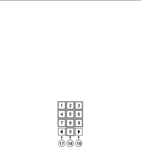
Figure 2: VS-1616D Front Panel Numeric Keypad
Table 2: VS-1616D Front Panel Numeric Keypad Labels
|
|
|
# |
|
Feature |
|
Function |
|
|
|
|
|
17 |
|
◄(Backward) |
|
Press to shift the sliding window to the right3 |
|
|
|
|
|
18 |
|
1, 2, 3, 4, 5, 6, 7, 8, 9, 0 |
|
|
Numeric keypad, 1 to 0 |
|
|
|
|
19 |
|
►(Forward) |
|
Press to shift the sliding window to the left3 |
|
|
|
|
|
|
|
|
|
|
|
|
1 |
After pressing the MENU button, this button lights and is enabled |
||||||||
2 |
For example, to enter input 5, you can press either ENT, 05 or 5 |
||||||||
3 |
Since the LCD display is large enough to show only 13 cross-points out of a total of 16 |
||||||||
|
|
|
|
|
|
|
|
|
|
8 |
|
|
|
|
|
|
KRAMER: SIMPLE CREATIVE TECHNOLOGY |
||

Defining the VS-1616D 16x16 Digital Matrix Switcher
Figure 3 and Table 3 define the rear panel of the VS-1616D showing DVI cards installed as an example.
Figure 3: VS-1616D 16x16 Digital Matrix Switcher Rear Panel Showing DVI cards
9

Defining the VS-1616D 16x16 Digital Matrix Switcher
Table 3: VS-1616D 16x16 Digital Matrix Switcher Rear Panel Features
# |
|
Feature |
|
|
Function |
21 |
|
AC Mains Power Module |
|
|
Fuse holder and power cord socket. Connect to the AC |
|
|
|
|
|
mains supply |
22 |
|
RS-232 9-pin D-sub Port |
|
|
Connects to the remote operation PC or remote controller1 |
|
|
|
|
|
(see Section 6.4) |
23 |
|
IN 1~4, 5~8 Connectors |
|
|
Connect to the relevant video sources, depending on the |
|
|
|
|
cards installed (1 to 8, see Section 6) |
|
|
|
|
INPUTS |
|
|
24 |
|
IN 9~12, 13~16 |
|
Connect to the relevant video sources, depending on the |
|
|
|
|
|||
|
|
Connectors |
|
|
cards installed (9 to 16, see Section 6) |
25 |
|
TEST Module |
|
|
Signal generator module for testing video outputs (see |
|
|
|
|
|
Section 10) |
26 |
|
RESOLUTION DIP-switches |
|
Set the resolution for video generated by the Test module |
|
|
|
|
|
|
(see Section 10.2) |
27 |
|
NET Ethernet RJ-45 Connector |
|
Connect to a PC or controller via the Ethernet LAN (see |
|
|
|
|
|
|
Section 6.5). |
|
|
|
|
|
LINK LED flashes when communication is active. POWER |
|
|
|
|
|
LED lights when the interface receives power |
28 |
|
OUT 1~4, 5~8 |
|
|
Connect to the relevant video acceptors, depending on the |
|
|
Connectors |
OUTPUTS |
|
cards installed (1 to 8, see Section 6) |
29 |
|
OUT 9~12, 13~16 |
|
Connect to the relevant video acceptors, depending on the |
|
|
|
|
|||
|
|
Connectors |
|
|
cards installed (9 to 16, see Section 6) |
30 |
|
Test Module Output Connector |
|
Connect to one of the relevant video inputs to aid in |
|
|
|
|
|
|
troubleshooting (see Section 10.4) |
31 |
|
PATTERN Button |
|
|
Press the button repeatedly to change the video pattern |
|
|
|
|
|
generated by the Test module (see Section 10.3) |
4.1 Using the IR Transmitter
You can use the RC-IR3 IR transmitter to control the machine via the built-in IR receiver on the front panel.
1 If the unit is not the first unit in the line, connects to the RS-232 OUT 9-pin DB port of the previous unit in the line
10 |
KRAMER: SIMPLE CREATIVE TECHNOLOGY |
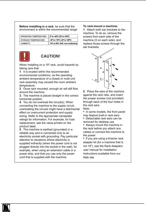
Installing the VS-1616D in a Rack
5 Installing the VS-1616D in a Rack
This section provides instruction on rack mounting the VS-1616D.
11
Connecting the VS-1616D 16x16 Digital Matrix Switcher
6 Connecting the VS-1616D 16x16 Digital Matrix Switcher
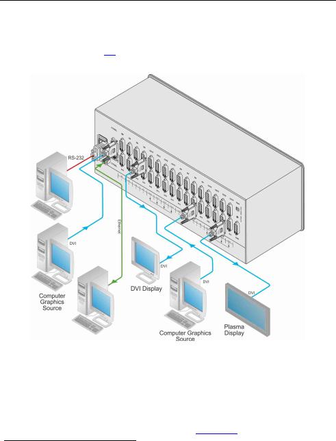
The configuration of DVI input/output cards shown in Figure 4 is merely an sample representation and different I/O cards may be mixed as required (for limitations, see Page 13). Exactly the same principles apply to installations using other card types.
Figure 4: Connecting the VS-1616D
To install1 the VS-1616D as illustrated in the example in Figure 4:
1.Connect up to 16 DVI video sources (for example2, computer graphics sources).
2.Connect up to 16 DVI video acceptors, (for example2, a plasma display and a DVI LCD display).
3.If required, connect a PC or remote controller to the RS-232 port (see Section 6.4) and/or the Ethernet port (see Section 6.5).
1 Switch off the power for each device before connecting it to your VS-1616D 2 In this example only two inputs and two outputs are connected
12 |
KRAMER: SIMPLE CREATIVE TECHNOLOGY |
Connecting the VS-1616D 16x16 Digital Matrix Switcher
4.Connect the power cord1.
5.If necessary, review and set the system configuration using the Menu (see Section 8).
Note: Given an input signal that is HDCP encoded, the VS-1616D will output a signal only if the output port to which it is switched supports HDCP.
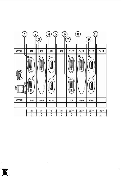
6.1 Port Numbering
Figure 5: Sample Port Numbering
Table 4: Port Numbering
|
Diagram # |
Actual Port Number |
Diagram # |
Actual Port Number |
1 |
|
IN 1 |
6 |
OUT 2 |
2 |
|
IN 2 |
7 |
OUT 1 |
3 |
|
IN 3 |
8 |
OUT 3 |
4 |
|
IN 5 |
9 |
OUT 5 |
5 |
|
IN 6 |
10 |
OUT 6 |
Note: There is no IN 4 or OUT 4 because these slots contain DVI dual link cards.
1 We recommend that you use only the power cord that is supplied with the device (not shown in Figure 4)
13
Connecting the VS-1616D 16x16 Digital Matrix Switcher
On all cards apart from the DVI dual link cards, there are two physical ports on each card and numbering of ports is sequential from top to bottom and left to right. Each DVI dual link card provides one physical port which causes the loss of one number in the numbering sequence of that card only. A sample numbering is shown in Figure 5 and explained in Table 4.
6.1.1 EDID Numbering Examples
Table 5 is based on the port numbering shown in Figure 5 and lists requested switching configurations and their results.
Table 5: EDID Configuration Requests and Results
EDID Request |
EDID Sent |
From OUT 4 |
Blank (256 bytes of 0xFF) |
From IN 8 |
None (error message displayed) |
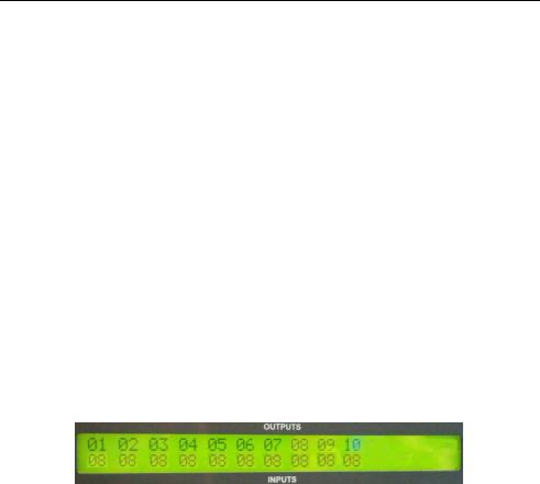
Note: AV data flow is: source > VS-1616D > display. EDID information flow is: display > VS-1616D > source, which means that the EDID input is the display side and the EDID output is the AV source side. This is the reverse of the AV data flow direction.
When assigning EDIDs, note that the top row of the LCD display labeled OUTPUTS relates to the ports connected to the sources (AV inputs), and the bottom row of the LCD display labeled INPUTS relates to the ports connected to displays (AV outputs).
In Figure 6, the EDID from EDID input 8 (VS-1616D Output port 8) has been assigned to all EDID outputs (VS-1616D Input ports).
Figure 6: EDID Numbering Assignment
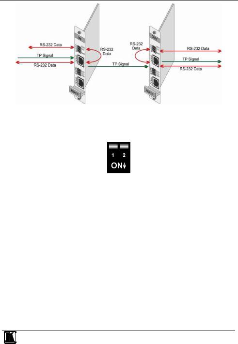
6.2 Serial Data Flow on DGKat Plus RS-232 Cards
Serial data present on the RS-232 port of a DGKat input card is not transmitted via the switcher. This data is transmitted over the TP cable of the same input card (see Figure 7).
Serial data present on the RS-232 port of a DGKat output card is not transmitted via the switcher. This data is transmitted over the TP cable of the same output card.
14 |
KRAMER: SIMPLE CREATIVE TECHNOLOGY |
Connecting the VS-1616D 16x16 Digital Matrix Switcher
Figure 7: DGKat Card Serial Data Transmission
6.3 Audio Mode Selection on HDMI plus Audio Cards
The Option dip-switches 1 and 2 (see Table 6) control the way audio is handled.
Figure 8: Audio Mode Selection on HDMI plus Audio Cards
Table 6: Audio Mode DIP-switch Operation
DIP- |
|
Description |
|
State |
|
Function |
switch # |
|
|
|
|
|
|
1 |
|
Auto/Manual |
|
Off |
|
Automatic—if an audio source is connected to the |
|
|
Mode |
|
(default) |
|
3.5mm mini jack the analog (external) audio is |
|
|
|
|
|
|
transmitted. If not, the embedded audio is transmitted |
|
|
|
|
On |
|
Manual—DisplayPort and HDMI ports always transmit |
|
|
|
|
|
|
the embedded audio and the VGA always transmits the |
|
|
|
|
|
|
analog audio. The DVI port audio is defined by DIP- |
|
|
|
|
|
|
switch 2 |
2 |
|
DVI Audio |
|
Off |
|
Only the DVI uses the embedded audio |
|
|
Source |
|
(default) |
|
|
|
|
|
|
On |
|
Only the DVI uses the analog (external) audio |
6.4Connecting to the VS-1616D via RS-232
You can connect to the VS-1616D via an RS-232 connection using, for example, a PC. Note that a null-modem adapter/connection is not required.
15

Connecting the VS-1616D 16x16 Digital Matrix Switcher
To connect to the VS-1616D via RS-232:
•Connect the RS-232 9-pin D-sub rear panel port on the VS-1616D unit via a 9-wire straight cable (only pin 2 to pin 2, pin 3 to pin 3, and pin 5 to pin 5 need to be connected) to the RS-232 9-pin D-sub port on your PC
6.5Connecting to the VS-1616D via Ethernet
You can connect the VS-1616D via Ethernet using a crossover cable (see Section 6.5.1) for direct connection to the PC, or a straight through cable (see Section 6.5.2) for connection via a network hub or network router1.
6.5.1Connecting the Ethernet Port directly to a PC
You can connect the Ethernet port on the VS-1616D to the Ethernet port on your PC via a crossover cable with RJ-45 connectors.
This type of connection is recommended for identification of the
factory-default IP Address of the VS-1616D during the initial configuration
To configure your PC after connecting the Ethernet port:
1.Right-click the My Network Places icon on your desktop.
2.Select Properties.
3.Right-click Local Area Connection Properties.
4.Select Properties.
The Local Area Connection Properties window appears.
5.Select the Internet Protocol (TCP/IP) and click the Properties Button.
1 After connecting the Ethernet port, you have to install and configure your Ethernet Port. For detailed instructions, see the Ethernet Configuration Guide (Lantronix) in the technical support section on our Web site http://www.kramerelectronics.com
16 |
KRAMER: SIMPLE CREATIVE TECHNOLOGY |
Connecting the VS-1616D 16x16 Digital Matrix Switcher
Figure 9: Local Area Connection Properties Window
6.Select Use the following IP Address and enter the details as shown in Figure 10. You can use any IP address in the range 192.168.1.1 to 192.168.1.255 (excluding 192.168.1.39) that is provided by your IT department.
17
Loading...