

Page 1

Kramer Electronics, Ltd.
USER MANUAL
Model:
VS-162V
16x16 Video Matrix Switcher
Page 2

Contents
i
Contents
1 Introduction 1
2 Getting Started 1
2.1 Quick Start 1
3 Overview 3
4 Your Video Matrix Switcher 4
4.1 Using the IR Transmitter 7
5 Installing the VS-162V in a Rack 8
6 Installing and Operating a Single VS-162V - Overview 9
7 Configuring the VS-162V Video Matrix Switcher 10
7.1 Configuring the Standalone VS-162V 10
7.1.1 Configuring a 16x16 Composite Video Switcher 10
7.1.2 Configuring an 8x8 s-Video (Y/C) Switcher 11
7.1.3 Configuring a 5x5 YUV/RGB Switcher 12
7.1.4 Configuring a 4x4 RGBS Switcher 12
7.2 Configuring 16x16 Multi-Channel Video Switchers 13
7.2.1 Configuring a 2-Unit 16x16 Y/C Switcher 13
7.2.2 Configuring a 3-Unit 16x16 YUV/RGB Switcher 14
7.2.3 Configuring a 4-Unit 16x16 RGBS Switcher 15
7.3 Configuring a Multi-Unit Matrix Switcher 15
7.3.1 Configuring a 32x16 Switcher 16
7.3.2 Configuring a 32x32 Switcher 17
7.4 Configuring a System of Interconnected Switchers 18
8 Understanding Addressing and System Modes 20
8.1 Setting the DIP-Switches 20
8.2 Setting the MACHINE # 21
8.3 Setting the MACHINE ADDRESS # 21
8.4 Understanding the SYSTEM Mode 21
8.5 Understanding the SLAVE Mode 22
9 Connecting a Control Interface 22
9.1 Connecting the RS-232 Control Interface 23
9.1.1 Connecting Two Units with a Null-Modem Adapter 24
9.1.2 Connecting Two Units without a Null-Modem Adapter 24
9.1.3 Connecting to a 9-pin PC COM Port with a Null-Modem Adapter 24
9.1.4 Connecting to a 9-pin PC COM Port without a Null-Modem Adapter 25
9.1.5 Connecting to a 25-pin PC COM Port with a Null-Modem Adapter 25
9.1.6 Connecting to a 25-pin PC COM Port without a Null-Modem Adapter 25
9.2 Connecting the RS-485 Control Interface 26
9.3 Configuring the Sync 29
9.4 Connecting the KEYBOARD EXTENSION 29
Page 3

KRAMER: SIMPLE CREATIVE TECHNOLOGY
Contents
ii
10 Operating Your Video Matrix Switcher 30
10.1 Startup Display 30
10.2 Using the Front Panel Buttons 31
10.3 Toggling Betwe en the AT ONCE and CONFIRM Modes 32
10.4 Switching 32
10.4.1 Switching One Input to One Output 32
10.4.2 Switching Several Inputs to Several Outputs 33
10.4.3 Switching One Input to All Outputs 34
10.5 Clearing 35
10.5.1 Clearing an Output 35
10.5.2 Clearing Several Outputs 36
10.5.3 Clearing All Outputs 37
10.6 Storing and Recalling Setups 37
10.6.1 Storing Setups 37
10.6.2 Recalling Setups 38
11 MENU Commands 39
11.1 Locking and Unlocking the Front Panel 41
11.2 Choosing the Follow or Breakaway from System Mode 42
11.3 Choosing the Video Format Setting 43
11.4 Setting the MACHINE ADDRESS 44
11.4.1 Changing the Stand alone MACHINE ADDRESS to a Large Matrix 45
11.4.2 Changing the Large Matrix M ACHINE ADDRESS to Standalone 46
11.4.3 Changing to a Different Lar ge Matrix MACHINE ADDRESS 47
11.5 Choosing the SWITCHING METHOD Setting 48
11.5.1 Understanding the SWITCHING METHOD Settings 48
11.5.2 Configuring a SWITCHING METHOD 50
11.6 Choosing the Extended Keyboard Setting 50
11.7 Setting the STORE/RECALL KEYBOARD Mode 51
11.8 Choosing the INDICATE Setting 51
11.9 Choosing the COMMUNICATION Setting 52
11.10 Setting the IR REMOTE Control 53
11.11 Choosing the AUTO STORE Current SETUP 54
11.12 Identifying the MACHINE 55
11.13 Choosing the Initial RESET 55
12 Upgrading the Flash Memory 56
12.1 Connecting the PC to the RS-232 Port 56
12.2 Upgrading the Firmware 57
13 Technical Specifications 59
14 Communication Protocol 59
Page 4

Contents
iii
Figures
Figure 1: VS-162V 16x16 Video Matrix Switcher 5
Figure 2: DIP-Switch Setup on a Single Machine 9
Figure 3: Configuring the VS-162V for Composite Video (CV) 11
Figure 4: Configuring the VS-162V for s-Video (Y/C) 11
Figure 5: Configuring the VS-162V for YUV (RGB) 12
Figure 6: Configuring the VS-162V for RGBS 12
Figure 7: Configuring a 16x16 YUV (RGB) Switcher with 3 VS-162V Units 14
Figure 8: MACHINE ADDRESS # Designation 15
Figure 9: Configuring a 32x16 Switcher 16
Figure 10: Connecting the 32x32 Switcher 18
Figure 11: Assembling a System of Interconnected Switchers 19
Figure 12: Rear Panel D IP-switches 20
Figure 13: Connecting a PC to 4 VS-162V Units 23
Figure 14: Connecting to a 25-pin PC COM Port without a Null-Modem Adapter 25
Figure 15: RS-485 Connector PI N O U T 26
Figure 16: Connecting the RS-485 Connectors between Two VS-162V Units 27
Figure 17: An RS-485 Control Interface Setup 28
Figure 18: Keyboard Extension (EXT. KEYS) Connector 30
Figure 19: Defaul t Startup Status Display Seq uence 31
Figure 20: Sequence of MENU Commands 40
Figure 21: Choosing the MTX (SYNC from Matrix) Setting 49
Figure 22: Choosing what to INDICATE 52
Figure 23: Machine Identification 55
Tables
Table 1: Front Panel VS-162V 16x16 Video Matrix Switcher Featur e s 6
Table 2: Quick Reference Operating Guide for a Single Machine 9
Table 3: Standalone Switcher Configuration for CV, Y/C, YUV (RGB) and RGBS 10
Table 4: 16x16 Multi-Channel Configurations 13
Table 5: DIP-switch Definitions 20
Table 6: Machine # DIP -Switch Settings 21
Table 7: Summary of Basic RC-IR2 Setups 53
Table 8: Summary of Basic RC-IR2 Operations 54
Table 9: Technical Specifications of the VS-162V Video Matrix Switcher 59
Table 10: Hex Table for the VS-162V Video Matrix Switcher 60
Page 5

Introduction
1
1 Introduction
Welcome to Kramer Electronics! Since 1981, Kramer Electronics has been
providing a world of unique, creative, and affordable solutions to the vast
range of problems that confront the video, audio, presentation, and
broadcasting professional on a daily basis. In recent years, we have
redesigned and upgraded most o f our line, making the best even better! Our
1,000-plus different models now appear in 11 groups
defined by function.
Congratulations on purchasing your Kramer VS-162V 16x16 Video Matrix
Switcher.
This product is ideal for:
• Professional display systems requiring video signal routing
• Broadcast, presentation and pro duction facilities
• Rental/staging applications
• Monitoring in large duplication syste ms
The package includes the following items:
• VS-162V 16x16 Video Matrix Switcher
®
• Windows
-based Kramer control software
• Power cord and null-modem adapter
• This user man ual
3
1
that are clearly
2
2 Getting Started
We recommend that you:
• Unpack the eq uipment carefully and save the original box and
packaging materials for possible future shipment
• Review the contents of t his user man ual
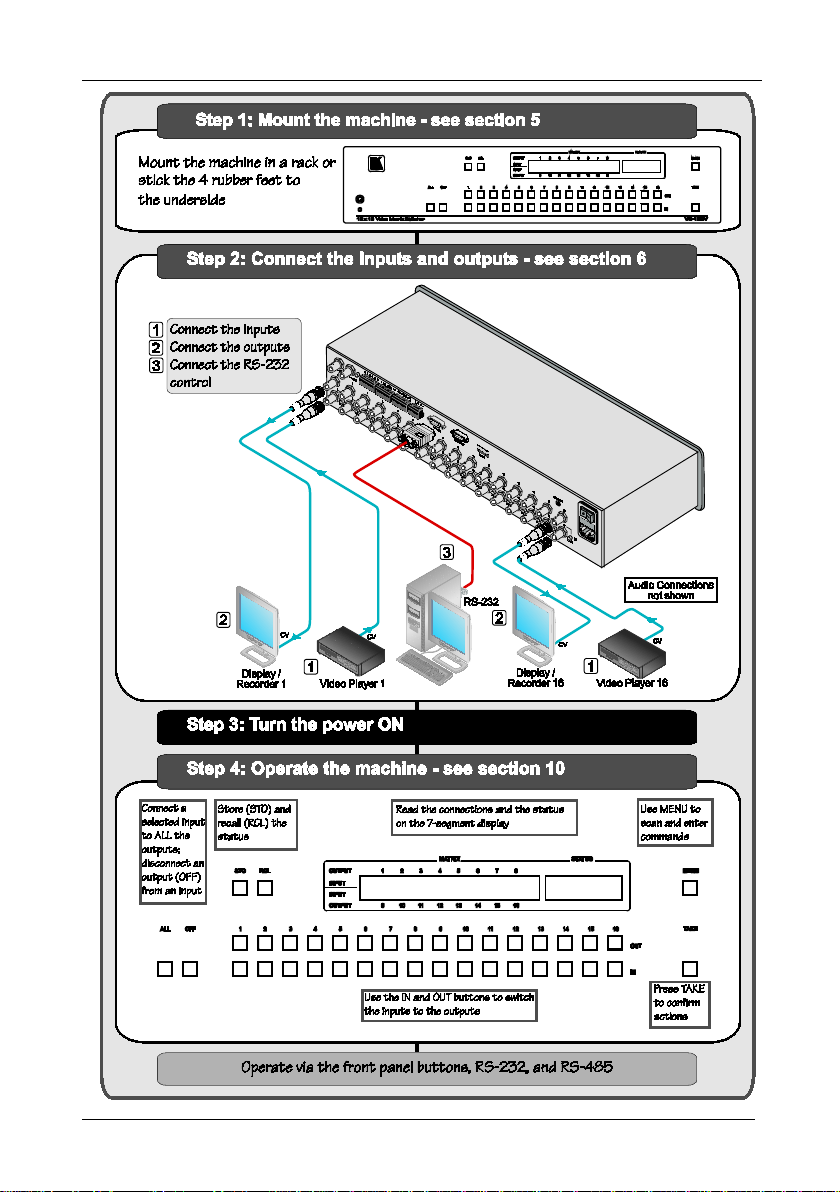
2.1 Quick Start
This quick start chart summarizes the basic setup and operation steps.
1 GROUP 1: Distribution Amplifiers; GROUP 2: Switchers and Matrix Switchers; GROUP 3: Control Systems; GROUP 4:
Format/Standards Converters; GROUP 5: Range Extenders and Repeaters; GROUP 6: Specialty AV Products; GR OUP 7:
Scan Converters and Scalers; GROUP 8: Cables and Connectors; GROUP 9: Room Conne ctivity; GROUP 10: Accessories
and Rack Adapters; GROUP 11: Sierra Products
2 Download the latest software from our Web site at http://www.kramerelectronics.com
3 Download up-to-date Kramer user manuals from our Web site at http://www.kramerelectronics.com
Page 6
KRAMER: SIMPLE CREATIVE TECHNOLOGY
Getting Started
2
Page 7

Overview
3
3 Overview
The Kramer VS-162V is a high-performance 16x16 vertical interval matrix
switcher for composite video signa ls o n BNC connectors. In addition to its
typical 16x16 operation, the VS-162V can be configured as follows:
• 8x8 for s-Video (Y/C)
• 5x5 for YUV or RGB (with the sync on the green signal - RG
• 4x4 for RGBS signals
A main advantage of the VS-162V is that it forms part of the series of
16x16 matrix switchers that includes, but is not limited to, VS-1616A (a
16x16 analog balanced stereo audio matrix switcher), VS-1616SDI (a
16x16 digital video matrix switcher ) , VS-1616AD (a 16x16 digital au dio
matrix switcher), and VS-1616RS (an RS-422 control signal matrix
switcher).
In particular, the VS-162V:
• Produces glitch-free transitio ns, when sources share a common
reference sync
• Offers excellent video performance, which ensures that it remains
transparent in almost any video application
In addition the VS-162V:
• May be used as a single unit, or expanded to up to 96 x 96
inputs/outputs
• Can be configured into a Kramer multi-signal switcher system
including digital and analog video, digital and analog audio, and
RS-422 control switchers
• When integrated in a system, a ll units switch in true audio-follow-
video mode
• Recalls up to 99 configuration setups via the non-volatile memory
and provides for an unlimited quantity of setups when us ing the
Kramer control software on your PC
• Includes a user-friendly LCD display (making operation even
easier)
• With its FLASH memory, lets you upgrad e to the latest Kramer
firmware version via Internet download
• Comes with a choice of protocol format: hexadecimal or ASCII
1
S
B)
1 As it switches during the vertical interval
Page 8

KRAMER: SIMPLE CREATIVE TECHNOLOGY
Your Video Matrix Switcher
4
You can control the VS-162V:
• Using the front panel buttons
• Remotely, b y RS-485 or RS-232 serial commands transmitted by
a touch screen system, PC, or other serial controller
• Remotely, from the Kramer RC-IR2 Infrared Remote Control
Transmitter
• An external remote IR receiver (optional), see section
• Via external dry-contact push buttons
To achieve the best performance:
• Connect only good quality connection cables, thus avoiding
interference, deterioration in signa l quality due to poor matching,
and elevated noise levels (often associated with low quality
cables)
• Avoid interference from neighboring electrical appliances that
may adverse ly influence signal quality and position yo ur Kramer
VS-162V in a location free from moisture and away from
excessive s unlight and dust
4 Your Video Matrix Switcher
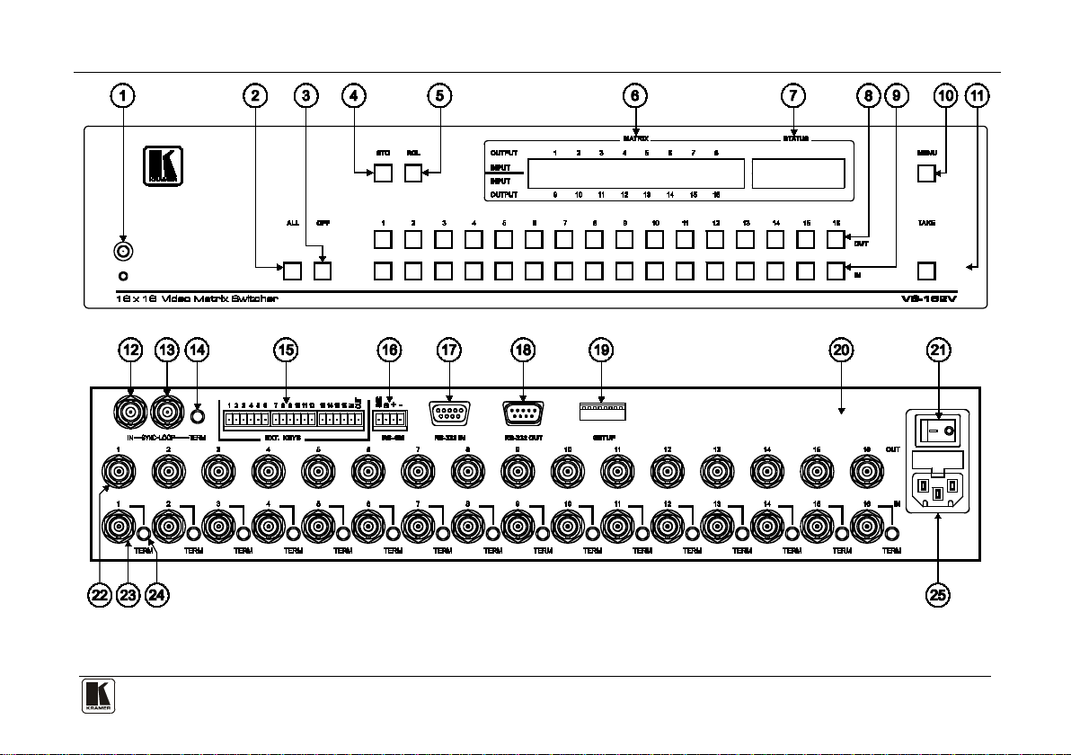
Figure 1 and Table 1 define the front and rear panels of the VS-162V.
4.1
Page 9
Your Video Matrix Switcher
5
Figure 1: VS-162V 16x16 Video Matrix Switcher
Page 10
KRAMER: SIMPLE CREATIVE TECHNOLOGY
Your Video Matrix Switcher
6
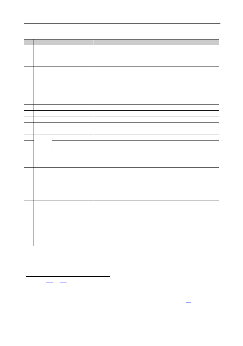
#
Feature
Function
1
2
Table 1: Front Panel VS-162V 16x16 Video Matrix Switcher Features
1 IR Receiver The red LED is illuminated when receiving signals from the Infrared
2 ALL Button Pressing ALL follow ed b y an INPUT button, connects that input to
3 OFF Button An OFF-OUT combination disconnects that output from the inputs; an
4 STO Button Stores the current setting in the non-volatile memory
5 RCL Button Recalls a setup from the non-volatile memory
6 LCD MATRIX display
7 LCD STATUS Display1 Displays the matrix status
8 OUT Buttons Select the output to which the input is switched (from 1 to 16)
9 IN Buttons Select the input to switch to the output (from 1 to 16)
10 MENU Button Selects the programming commands to setup the switcher
11 TAKE Button Used t o conf irm an d co mplete set up and switching
SYNC
12
13 LOOP BNC
14 TERM SYNC Button Press to terminate at 75Ω or release for looping
15 EXT. (extension) KEYS
Terminal Block Connectors
16 RS-485 Detachable Terminal
Block Port
17 RS-232 IN 9-pin D-sub (F) Port Connects to the PC or the Remote Controller
18 RS-232 OUT 9-pin D-su b ( M)
Port
19 SETUP DIP-Switches DIP-switches for setup of the unit
20 REMOTE IR 3.5mm Mini Jack Connect to an external IR receiver unit for controlli ng th e machine
21 Power Switch Illuminated switch for turning the unit ON or OFF
22 OUT BNC Connectors Connect to the video acceptors (from 1 to 16)
23 IN BNC Connectors Connect to the video sou rc e s (from 1 to 16)
24 TERM IN Buttons Press to terminate at 75Ω or release for looping
25 Power Connector with Fuse AC connector enabling power supply to the unit
IN BNC Connector Connects to the external video sync source
Connector
remote control transmitter
all outputs
OFF-ALL combination disconnects all the outputs
Displays the selected input(s) switched to the output(s) (above or
below the corresponding OUTPUT label) and user interface
messages
Connects to the SYNC IN connector on the next unit
Connects to an external keyboard (remote unit)
Pins # 1 and # 2 are for vertical sync and Ground connection, and
Pins # 3 and # 4 are for RS 485
Connects to the RS-232 IN 9-pin D-sub port of the next unit in the
daisy-chain connection
via an IR remote controller (ins t ea d of usi ng the front pa nel IR
4
receiver)
3
5
1 In sections 11.1 and 12.2 the word “Displays” refers to the LCD MATRIX and STATUS Displays
2 Push in to terminate the sync line. Push out when the sync line extends to another unit
3 If the unit is not the first unit in the line, connects to the RS-232 OUT 9-pin D-sub port of the previous unit in the line
4 Can be used instead of the front panel (built-in) IR receiver to remotely control the machine, see section
5 Push in to terminate the input. Push out when the input extends to another unit (the last unit in the chain must be terminated
when looping)
4.1
Page 11

Your Video Matrix Switcher
7 7
4.1 Using the IR Transmitter
You can use the RC-IR2 IR transmitter to control the machine via the builtin IR receiver on the front panel or, instead, via an optional external IR
receiver
machine. This distance can be extended to up to 60 meters when used with
three extension cables
1
. The external IR receiver can be located 15 meters away from the
2
Before using the external IR receiver, be sure to arrange for your Kramer
dealer to insert the internal IR connection cable
3
11F
with the 3.5mm connector
that fits into the REMOTE IR opening on the rear panel. Connect the
external IR receiver to the REMOTE IR 3.5mm connector.
1 Model: C-A35M/IRR-50
2 Model: C-A35M/A35F-50
3 P/N: 505-70434010-S
Page 12
KRAMER: SIMPLE CREATIVE TECHNOLOGY
Installing the VS-162V in a Rack
8
!
CAUTION
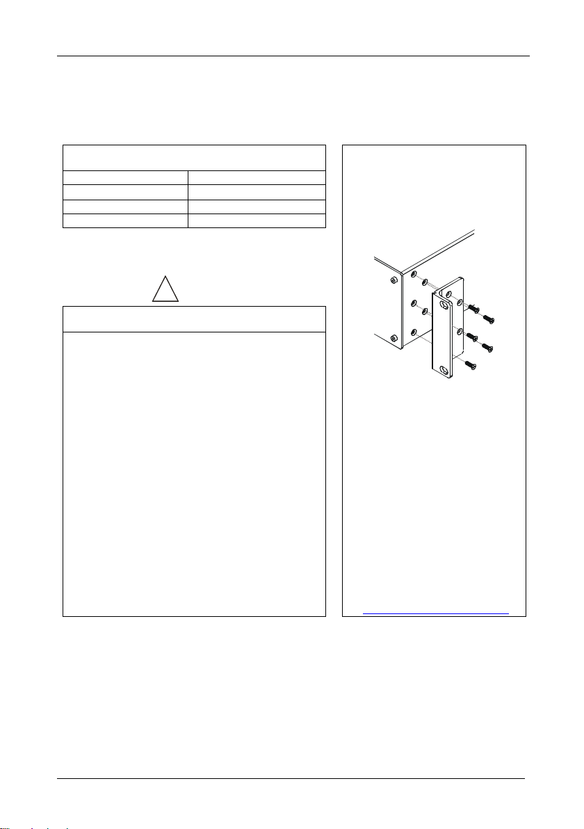
5 Installing the VS-162V in a Rack
This section describes what to do before installing in a rack and how to rack
mount.
Before Installing in a Rack
Before installing in a rack, be sure that the environment is
within the recommended range:
Operating temperature range +5º to +45º C (41º to 113º F)
Operating humidity range 10 to 90% RHL, non-condensing
Storage temperature range -20º to +70º C (-4º to 158º F)
Storage humidity range 5 to 95% RHL, non-condensing
.
To rack-mount a machine:
1. Attach both ear brackets to the
How to Rack Mount
machine. To do so, remove the
screws from each side of the
machine (3 on each side), and
replace those screws through the
ear brackets.
When installing in a 19" rack, avoid hazards by taking
care that:
1. It is located within the recommended environmental
conditions, as the opera ting ambient temperature of a
closed or multi unit rack assembly may exceed the
room ambient temperature.
2. Once rack mounted, enough air will still flow around
the machine.
3. The machine is placed straight in the correct
horizontal position.
4. You do not overload the circuit(s). When connecting
the machine to the supply circuit, overloading the
circuits might have a detrimental effect on overcurrent
protection and suppl y wiri ng. Refer to the appropriate
nameplate ratings for information. For example, for
fuse replacement, see the v al ue printed on the
product label.
5. The machine is earthed (grounded) in a reliable way
and is connected only to an electri city socket with
grounding. Pay particular attention to situations where
electricity is supplied indirectly (when the power cord
is not plugged directly into the socket in the wall), for
example, when using an extension cable or a power
strip, and that you use only the power cord that is
supplied with the machine.
!!
2. Place the ears of the machine
against the rack rails, and insert the
proper screws (not provided)
through each of the four holes in the
rack ears.
Note that:
• In some models, the front panel
may feature built-in rack ears
• Detachable rack ears can be
removed for desktop use
• Always mount the machine in the
rack before you attach any ca bles
or connect the machine to the
power
• If you are using a Kramer rack
adapter kit (for a machine that is not
19"), see the Rack Adapters user
manual for installation instructions
(you can download it at:
http://www.kramerelectronics.com
)
Page 13
Installing and Operating a Single VS-162V - Overview
9 9
6 Installing and Operating a Single VS-162V - Overview
9
1
to the rear panel, as
8
To install the VS-162V, connect the followi ng
required:
• Power cord
• Video input and output cables
• Control interface cables between switcher units, or PC (or other
controller), as described in section
• Set the DIP-switches, as described in section
• Set the system variables using the MENU function, as described
in section
11
By default, the VS-162V is setup for operation as a single machine.
This means that it is:
• A 16x16 composite video switcher
• Switched during the vertical interval of the external reference
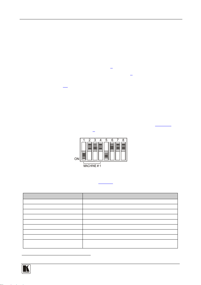
In particular, be sure that the DIP-switches are set as shown in
more information, see section
8):
Figure 2 (for
Figure 2: DIP-Switch Setup on a Si n gl e Mac hine
To operate a single machine, see Table 2.
Table 2: Quick Reference Operating Gui de for a Single Machine
To perform this command: Press:
Connect an input with an outpu t OUT #; IN #
Reset a specific output OUT #; OFF
Reset all outputs ALL; OFF
Connect all outputs to a specific input ALL; IN #
Store a setup STO; OUT #; TAKE
Recall a setup RCL; OUT #; TAKE
Lock front panel MENU; TAKE
Unlock front panel TAKE; TAKE
Change default setup Press the Menu button several times until you reach the
1 Switch OFF the power on each device before connecting it to your VS-162V
appropriate Menu setup c om m an d and fol lo w the instructions
Page 14
KRAMER: SIMPLE CREATIVE TECHNOLOGY
Configuring the VS-162V Video Matrix Switcher
10
7 Configuring the VS-162V Video Matrix Switcher
Using the VS-162V unit and/or other 16x16 matrix switchers in the series
you can assemble the fol lowing ki nds of systems:
• A standalone switcher (see section
• A multi-channel video switcher (see section
• An expanded matrix switcher (see section
• A system of interconnected switchers (see section
Note: When configuring multiple units, each unit must have an address. For
an explanation on addressing and system modes, see section 8
7.1 Configuring the Standalone VS-162V
This section describes how to co nfi g ur e your VS-162V as a standalone
switcher for:
• Composite video (CV) (see secti on
• s-Video (Y/C) (see section
• YUV (RGB) (see section
• RGBS (see section
7.1.4)
7.1.2)
7.1.3)
Table 3 defines the number of inputs and outputs for each signal
configuration:
Table 3: Standalone Switcher Configuration for CV, Y/C, YUV (RGB) and RGBS
Configuration Number of Inputs and Outputs
Composite 16x16
s-Video (Y/C) 8x8
YUV / RGB 5x5
RGBS 4x4
on a Standalone Unit
7.1)
7.2)
7.3)
7.4)
7.1.1)
1
,
.
7.1.1 Configuring a 16x16 Composite Video Switcher
By default, a single VS-162V unit is configured for composite video with
16 inputs and 16 outputs, as shown in
1 Including the VS-1616A (a 16x16 analog balanced stereo audio matrix switcher), the VS-1616SDI (a 16x16 digital video
matrix switcher), and the VS-1616AD (a 16x16 digital audio matrix switcher)
Figure 3:
Page 15
Configuring the VS-162V Video Matrix Switcher
11 11
Figure 3: Configuring the VS-162V for Composite Video (CV)
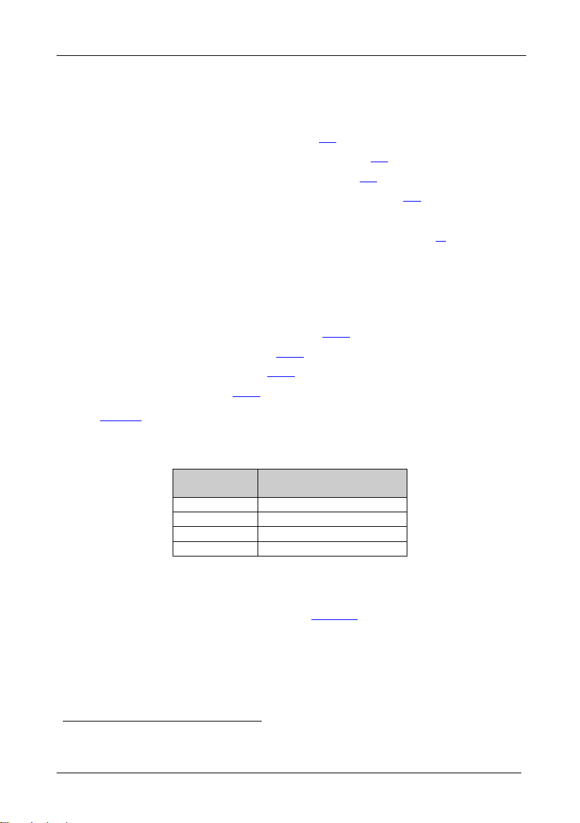
7.1.2 Configuring an 8x8 s-Video (Y/C) Switcher
To configure a single VS-162V switcher as an 8x8 video matrix switcher
(with 8 inputs and 8 outputs) for s-Video (Y/C), group the inputs and
outputs into pairs, as shown in
Figure 4: Configuring the VS-162V for s-Video (Y/C)
Figure 4:
Page 16
KRAMER: SIMPLE CREATIVE TECHNOLOGY
Configuring the VS-162V Video Matrix Switcher
12
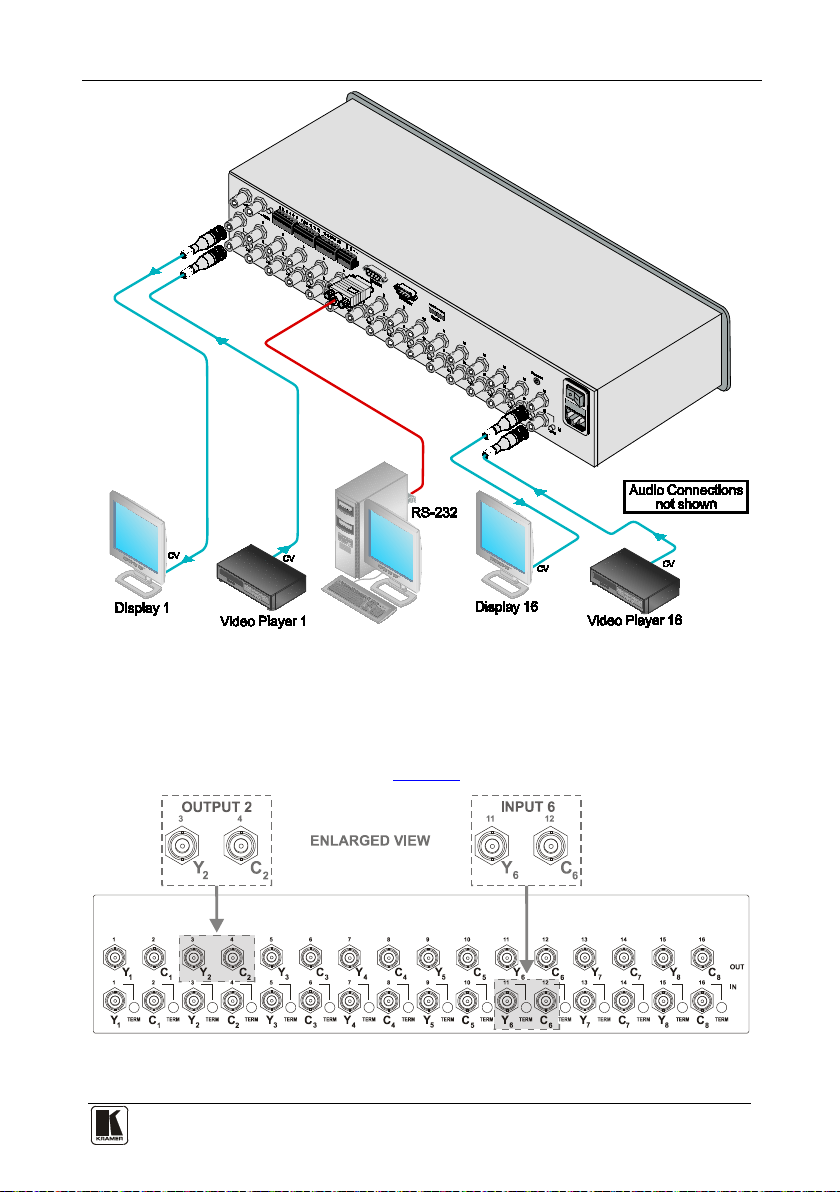
7.1.3 Configuring a 5x5 YUV/RGB Switcher
To configure a single VS-162V switcher as a 5x5 vide o matrix switcher for
YUV (or RGB), group the inputs and outputs
Figure 5
. The YUV channel is also appropriate for RG
1
into sets of 3, as shown in
B. In this case,
S
connect Gs for Y, R for V and B for U.
Figure 5: Configuring the VS-162V for YUV (RGB)
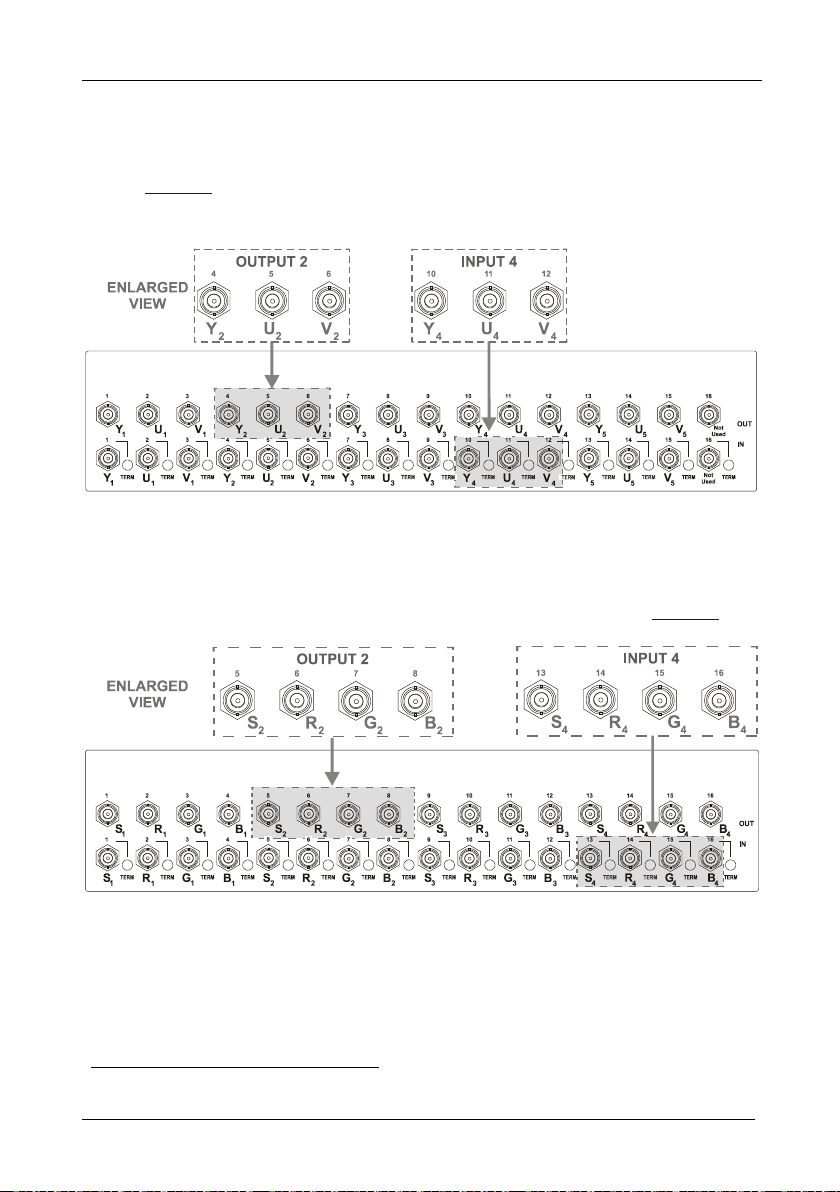
7.1.4 Configuring a 4x4 RGBS Switcher
To configure a single VS-162V switcher as a 4x4 vide o matrix switcher for
RGBS, group the inputs and outputs into sets of 4, as shown in
Figure 6:
1 Input 16 and output 16 are not used
Figure 6: Configuring the VS-162V for RGBS
Page 17
Configuring the VS-162V Video Matrix Switcher
13 13
7.2 Configuring 16x16 Multi-Channel Video Switchers
You can configure VS-162V units as a 16x16 multi-channel video switcher
for:
• s-Video (Y/C) (see section
• YUV (RGB) (see section
• RGBS (see section
7.2.3)
7.2.1)
7.2.2)
You may need several VS-162V units to expand the system, as
defines. For example, for composite configuration, a single VS-162V unit
provides 16 inputs and 16 outputs. However, for s-Video (Y/C)
configuration you need two VS-162V units to provide 16 inputs and 16
outputs.
In a multi-channel video switcher configuration, one unit must be the master
(with DIP 6 OFF) while the other units are slaves (with DIP 6 ON).
The front panel of each slave unit is always locked and the MATRIX and
STATUS LCD displays do not illuminate. The slave units follow the master.
The master unit operates in the regular way
1
, leading the slaves in the
background.
Note: To activate a multi-channel video switcher so that each unit is in the
same state from the outset, turn on the master unit power before turning on
the slave units.
Table 4: 16x16 Multi-Channel Configurations
Configuration No. VS-162Vs Needed to
Composite 1
s-Video (Y/C) 2
YUV / RGB 3
RGBS 4
7.2.1 Configuring a 2-Unit 16x16 Y/C Switcher
Make a 16x16 Switcher
To configure a 16x16 s-Video (Y/C) video matrix switcher, combine two
VS-162V switchers. Connect as shown in Figure 7, substituting the C unit
for the U unit and ignoring the V unit. Set the DIP-switches as shown in
Figure 7. Connect the communication line via the RS-232 or RS-485 control
interface as described in section 9.
Table 4
1 The front panel is not locked and the MATRIX and STATUS LCD Displays illuminate
Page 18
KRAMER: SIMPLE CREATIVE TECHNOLOGY
Configuring the VS-162V Video Matrix Switcher
14
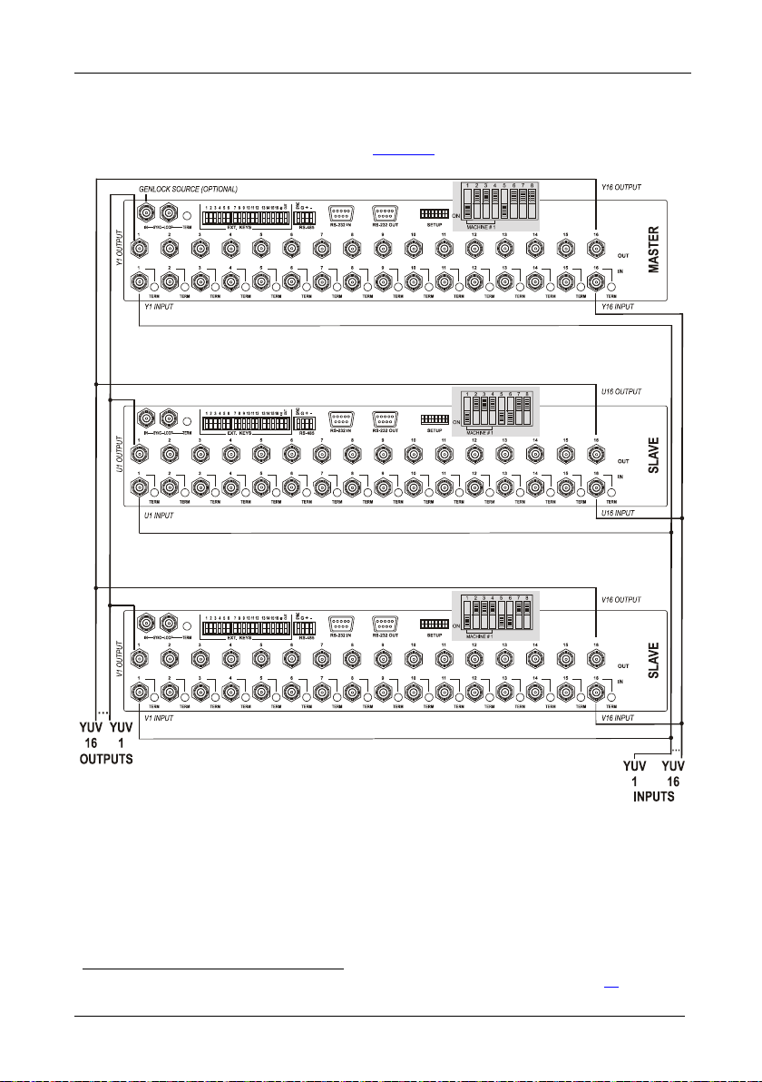
7.2.2 Configuring a 3-Unit 16x16 YUV/RGB Switcher
To configure a 16x16 YUV video matrix switcher, combine
VS-162V switchers, as shown in :
Figure 7
1
three
Figure 7: Configuring a 16x16 YUV (RGB) Switcher with 3 VS-162V Units
1 For a description of how to connect the RS-485 connectors between the VS-162V switchers, refer to section 9.2
Page 19
Configuring the VS-162V Video Matrix Switcher
15 15
OUTPUTS 1-16 OUTPUTS 65-80OUTPUTS 49-64OUTPUTS 17-32
INPUTS
17-32
INPUTS
1-16
INPUTS
33-48
INPUTS
49-64
INPUTS
65-80
MACHINE
ADDRESS # 7
MACHINE
ADDRESS # 1
MACHINE
ADDRESS # 13
MACHINE
ADDRESS # 19
MACHINE
ADDRESS # 25
MACHINE
ADDRESS # 31
MACHINE
ADDRESS # 8
MACHINE
ADDRESS # 2
MACHINE
ADDRESS # 14
MACHINE
ADDRESS # 20
MACHINE
ADDRESS # 26
MACHINE
ADDRESS # 32
INPUTS
81-96
OUTPUTS 33-48
MACHINE
ADDRESS # 9
MACHINE
ADDRESS # 3
MACHINE
ADDRESS # 15
MACHINE
ADDRESS # 21
MACHINE
ADDRESS # 27
MACHINE
ADDRESS # 33
MACHINE
ADDRESS # 10
MACHINE
ADDRESS # 4
MACHINE
ADDRESS # 16
MACHINE
ADDRESS # 22
MACHINE
ADDRESS # 28
MACHINE
ADDRESS # 34
MACHINE
ADDRESS # 11
MACHINE
ADDRESS # 5
MACHINE
ADDRESS # 17
MACHINE
ADDRESS # 23
MACHINE
ADDRESS # 29
MACHINE
ADDRESS # 35
OUTPUTS 81-96
MACHINE
ADDRESS # 12
MACHINE
ADDRESS # 6
MACHINE
ADDRESS # 18
MACHINE
ADDRESS # 24
MACHINE
ADDRESS # 30
MACHINE
ADDRESS # 36
7.2.3 Configuring a 4-Unit 16x16 RGBS Switcher
To configure four VS-162V switchers as a 16x16 RGBS video matrix
switcher, combine three VS-162V s witchers for YUV (RGB) as shown in
Figure 7.
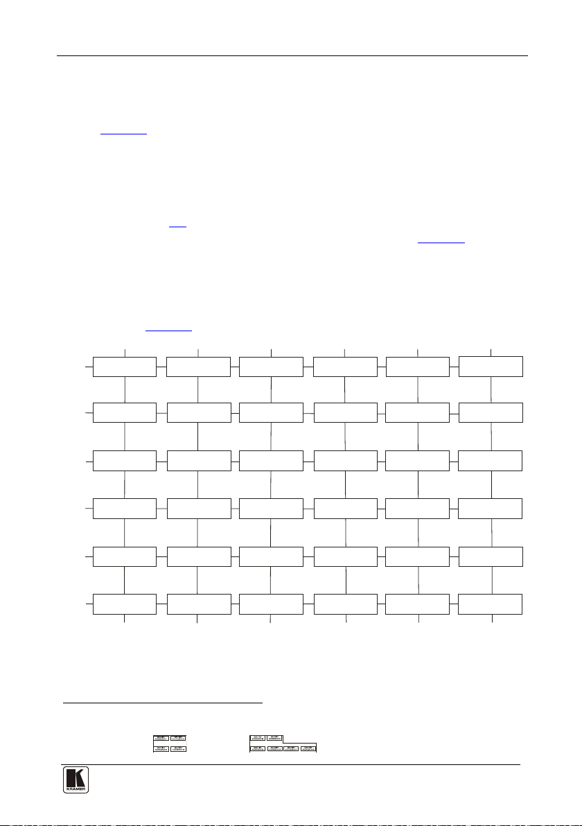
7.3 Configuring a Multi-Unit Matrix Switcher
You can greatly expand the number of input s and outputs using several VS162V units
(see section ) on each VS-162V unit. This defines which inputs and
outputs are configured to a particular unit, as the chart in
1
. To do this, you must s et a unique MACHINE ADDRES S #
8.3
Figure 8
illustrates.
For example, to connect a 48x64 switcher (48 inputs and 64 outputs), you
would configure using MACHINE ADDRESS # 1, 2, 3, 4; 7, 8, 9, 10; 13,
14, 15 and 16. You can only choose a rectangular
chart in .
Figure 8
2
configuration from the
1 For example, a 32 x32 switcher and a 32x16 switcher. In fact, you can connect up to 36 units to for m a switcher with 96
inputs and 96 outputs
2 For example, like this:
Figure 8: MACHINE ADDRESS # Designation
but not like this:
Page 20
KRAMER: SIMPLE CREATIVE TECHNOLOGY
Configuring the VS-162 V Video Matrix Switc her
16
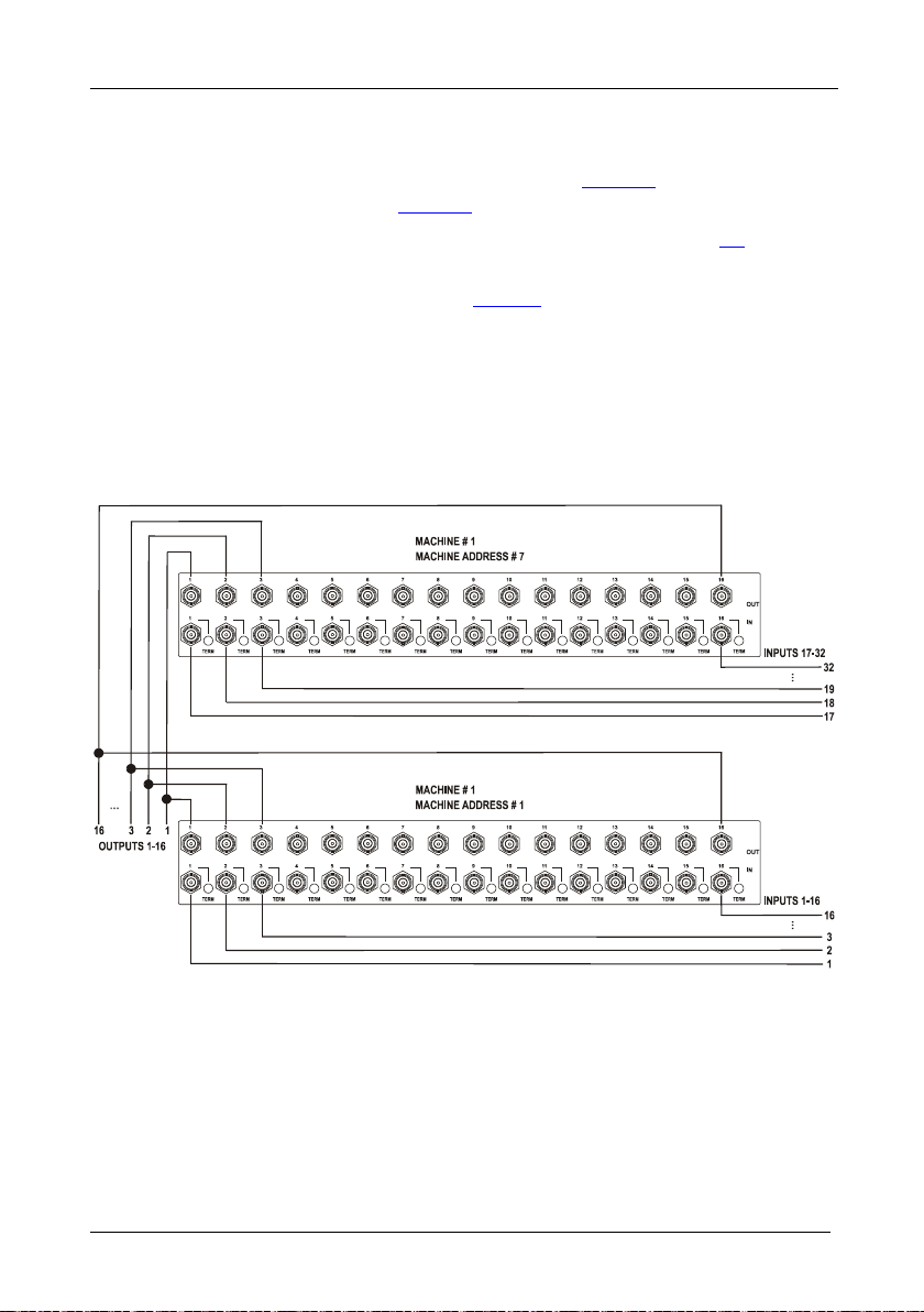
7.3.1 Configuring a 32x16 Switcher
A 32x16 switcher consist s of two VS-162V units (MACHINE ADDRESS #
1 and MACHINE ADDRESS # 7), as shown in
configuration, as shown in
Figure 9:
Figure 8. To make this
1. Set the MACHINE # on both VS-162V units to #1 (see section
2. Set the MACHINE ADDRESS # on one VS-162V unit to 1 and on the
other VS-162V unit to 7 (refer to
Figure 8).
3. Set DIP 6 OFF on both VS-162V units.
4. Using T-connectors, connect OUTPUTS 1 to 16 on both VS-162V units.
OUTPUTS 1 to 16 become the SYSTEM OUTPUTS 1 to 16, while the
inputs on the MACHINE ADDRESS # 1 are system inputs 1 to 16, and the
inputs on the MACHINE ADDRESS # 7 are system inputs 17 to 32.
The two VS-162V units form a 32x16 switcher.
8.2).
Figure 9: Configur ing a 32x16 Switc her
Page 21

Configuring the VS-162V Video Matrix Switcher
17 17
7.3.2 Configuring a 32x32 Switcher
As shown in Figure 8, a 32x32 switcher consists of four VS-162V units
(MACHINE ADDRESS # 1, MACHINE ADDRESS # 2, MACHINE
ADDRESS # 7 and MACHINE ADD RESS # 8). To a ssemble, as shown in
Figure 10:
1. Set the same MACHINE #
1
on all the four VS-162V units.
2. Set the MACHINE ADDRESS # to 1, 2, 7 and 8 on each of the four units,
respectively (refer to
Figure 8).
3. Set DIP 6 OFF on each of the four VS-162V units.
4. Using T-connectors, connect INPUTS 1 to 16 on the VS-162V unit
designated as MACHINE ADDRESS # 2 with INPUTS 1 to 16 on the VS-
162V unit designated as MACHINE ADDRESS # 1.
5. Terminate the INPUTS on MACHINE ADDRESS # 2 to 75Ω (push in the
TERM button
2
next to the INPUT BNCs) and put the inputs in MACHINE
ADDRESS # 1 into Hi-Z state (release the TERM buttons next to the
INPUT BNCs).
INPUTS 1 to 16 become the SYSTEM INPUTS 1 to 16.
6. Using T-connectors, connect INPUTS 17 to 32 on the VS-162V unit
designated as MACHINE ADDRESS # 8 with INPUTS 17 to 32 on the
VS-162V unit designated as MACHINE ADDRESS # 7.
7. Terminate the INPUTS on MACHINE ADDRESS # 8 to 75 Ω (push in the
TERM button next to the INPUT BNCs) and put the inputs in MACHINE
ADDRESS # 7 into Hi-Z state (release the TERM buttons next to the
INPUT BNCs).
INPUTS 17 to 32 become the SYSTEM INPUTS 17 to 32.
8. Using T-connectors, connect OUTPUTS 1 to 16 on the VS-162V unit
designated as MACHINE ADDRESS # 7 with OUTPUTS 1 to 16 on the
VS-162V unit designated as MACHINE ADDRESS # 1.
OUTPUTS 1 to 16 become the SYSTEM OUTPUTS 1 to 16.
9. Using T-connectors, connect OUTPUTS 17 to 32 on the VS-162V unit
designate d as MA CHIN E A DDRESS # 8 with OUTPUTS 17 to 32 on the
VS-162V unit designated as MACHINE ADDRESS # 2.
OUTPUTS 17 to 32 become the SYSTEM OUTPUTS 17 to 32.
The 4 VS-162V units form a 32x32 switcher.
1 Set to # 1 in most cases. In the example in Figure 10, the MACHINE # is set to # 2
2 Item 10 on the rear panel in
Figure 1
Page 22

KRAMER: SIMPLE CREATIVE TECHNOLOGY
Configuring the VS-162V Video Matrix Switcher
18
Figure 10: Conne c t ing the 32x32 Switche r
7.4 Configuring a System of Interconnected Switchers
A major advantage of the VS-162V is that it belongs to the series of 16x16
matrix switchers that can interconnect with other switchers in the series.
This series includes, but is not li mited to, VS-1616A (a 16x16 analog
balanced stereo audio matrix switcher), VS-1616SDI (a 16x16 digital video
matrix switcher), VS-1616AD (a 16x16 digital audio matrix switcher), and
VS-1616RS (an RS-422 control signal matrix switcher).
The block diagram in
interconnected varied-format 16x16 series switcher that consists of a 32x32
composite video matrix switc her , a 32x16 digital video matrix switcher, a
32x32 balanced stereo audio matrix switcher, and a 16x16 digital audio
matrix switcher.
Note that each group of switchers has a unique MACHINE # that is shared
by all members of the group. In
matrix switcher is MACHINE # 1, the 32x16 digital video matrix switcher
is MACHINE # 2 and so on. Control of the system is via the MACHINE #s.
Figure 11 illustrates how to assemble an
Figure 11, the 32x32 composite video
Page 23

Configuring the VS-162V Video Matrix Switcher
19 19
Figure 11: Assembling a System of Interconnect ed Switchers
Refer to section 8.1 for how to set the DIP-switches, and to section 9 for
how to control this group of interconnected varied-format 16x16 series
switchers, and other configura t ions.
Page 24

KRAMER: SIMPLE CREATIVE TECHNOLOGY
Understanding Addressing and System Modes
20
DIP-switch #
Function:
8 Under standing Addressing and System Modes
In order to control multiple machines, the VS-162V uses a system of
addressing that includes hardware DIP-switches and menu commands. The
DIP-switches are used to set the MACHINE# and menu commands are used
to set the MACHINE ADDRESS #. Note the following :
• A standalone machine is always set to MACHINE# 1
• When configur ing multiple VS-162V units or a matrix of VS-162V
machines, the array is viewed as one large unit and the DIP-switches
of all machines are set to the same MACHINE#. However, each
machine is set to a unique MACHINE ADDRESS # with a menu
command on its display panel according to the addressing rule shown
Figure 8
in
• When configuring a mix of different model machines, each group of
models receives a different MACHINE# and each machine is set to a
unique MACHINE ADDRESS # (see section
8.1 Setting the DIP-Switches
7.4).
Configure the VS-162V by setting the 8 DIP-switches as
Figure 12 and
Table 5 define:
Figure 12: Rear P ane l DIP-switches
Table 5: DIP-switch Definitions
1-4 Set the MACHINE # (see Table 6 in section 8.2)
5 Enables (ON) or disables (OFF) the Follow-SYSTEM mode
6 Enables (ON) or disables (OFF) the SLAVE mode in a multi-channel configuration
7 Disables use of a null-modem adapter
8 RS-485 termination for first and last machine = ON (RS-485 line terminates with
1 See section 9.1
OFF = RS-232 connection via a null-modem adapter
ON = RS-232 connection with out a null-modem adapter
110Ω); for others = OFF (RS-485 line is open)
1
with RS-232
Page 25

Understanding Addressing and System Modes
21 21
DIP-SWITCH
MACHINE #
DIP-SWITCH
8.2 Setting the MACHINE #
To contro l a unit via RS-232 or RS-485, each unit must be identified via its
unique MAC HINE #. In an extended matrix configuration, in addition to
the MACHINE #, each unit is identi fied via its MACHINE ADDRESS #.
Set the MACHINE #
1
Table 6 on a VS-162V unit acco rding to .
A valid MACHINE # is from 1 to 15. 0 is not a valid address.
Table 6: Machine # DIP-Switch Settings
MACHINE #
1
2 OFF
3
4 OFF OFF
5
6 OFF
7
8 OFF OFF OFF
1 2 3 4 1 2 3 4
ON
OFF OFF OFF 9
ON
OFF OFF 10 OFF
ON ON
ON
ON ON ON
OFF OFF 11
ON
ON
OFF
ON ON
OFF 12 OFF OFF
OFF 13
OFF 14 OFF
OFF 15
ON
ON
OFF OFF
ON
OFF
ON ON
ON
ON ON ON ON
OFF
ON ON
ON ON
OFF
ON ON ON
8.3 Setting the MACHINE ADDRESS #
The MACHINE ADDRESS # is determined via the MACHINE ADDRESS
Menu command, as section
11.4 describes. The MACHINE ADDRESS #
defines whi ch inputs and outputs are configured to that particular unit when
expanding, as the chart in
Figure 8 illustrates.
ON
ON
ON
A valid MACHINE ADDRESS # is from 1 to 36.
8.4 Understan ding the SYSTEM Mode
DIP-switch 5 defines whether the VS-162V unit communicates with other
switchers via a common control line.
You can set DIP 5 OFF to disable the Follow-SYSTEM mode in the
following applications:
2
• Standalone switcher applications
• A multi-channel video switcher application
• An expanded matrix switcher applica tion
1 When using a single unit, set the unit to MACHINE # 1
2 See section 7.1
3 See section
4 See section
7.2
7.3
3
4
Page 26

KRAMER: SIMPLE CREATIVE TECHNOLOGY
Connecting a Control Interface
22
You must set D IP 5 ON to enable the Follow-SYSTEM mode in an
interconnected varied-format switcher application
1
For a description of the Follow-SYSTEM and Breakaway-from-SYSTEM
.
menu modes, see section
11.2
8.5 Understa n d ing the SLAVE Mode
The SLAVE mode is only used for the multi-channel video switcher
configuration
YUV switcher, as shown in .
2
, for example , when using three VS-162V units to form a
Figure 7
One unit is use d as the master, and the other two units are slaves. The slaves
always follo w the master. In the example shown in
Figure 7, the first
VS-162V unit is the master (w ith DIP 6 set OFF disabling the slave mode)
and the second and third VS-162V units are slaves (with DIP 6 set ON
enabling t he slave mode).
On both slave VS-162V units, the MATRIX and STAT US D isp lays do not
illuminate and the STATUS Display shows the following messa ge:
Keyboard LOCKED
However, the STATUS Display on each slave VS-162V unit dynamically
3
all changes made from the master VS-162V unit.
shows
Front panel control is via the master VS-162V unit, on which the fr ont panel
buttons are unlocked and both the MATRIX and STATUS displays
illuminate.
9 Connect i ng a Control Interface
Connect a control interface (RS-232 or RS-485) unless operating a
VS-162V as a standalone unit without any control device ( that is, with
control from the front panel or IR port, and not via a remote controller or a
PC).
The control interface must be identical on each switcher in the series of
16x16 matrix switchers; either RS-232 or RS-485. One control interface
suffices. Do not use both RS-232 and RS-485 control interfaces in the sa me
configuration. For example, in an interconnected varied-format 16x16
switcher application
1 See section 7.4
2 See section
3 Albeit with an LCD Display that does not illuminate
7.2
1
, if the switcher that connects to the PC connects via
Page 27

Connecting a Control Interface
23 23
the RS-232 control interface, each switcher must interconnect via the
RS-232 control interface and not via the RS-485 control interface.
Choose the RS-232 control interface for a point-to-point connection with a
range of about 25 meters.
Choose the RS-485 control interface to operate the switcher from an
extended distance of up to 1000 meters.
9.1 Connecting the RS-232 Control Interface
Connect several switchers (from the series of 16x16 matrix switchers) and
the control unit in an RS-232 daisy chain arrangement, with or without
using a null-modem adapter, as shown in
Figure 13
.
The RS-232 daisy chain switcher arrangement is transpa rent. Thi s lets you
arrange the switchers (from the series of 16x16 matrix switchers) according
to your req uirements, and not according to a fixed sequence dependent on
the MACHINE # and/or MACHINE ADDRESS #.
Figure 13: Connecting a PC to 4 VS-162V Units
Page 28

KRAMER: SIMPLE CREATIVE TECHNOLOGY
Connecting a Control Interface
24
You can connect any of the following:
• Two VS-162V units, using a null-modem adapter (see section
9.1.1) or without using a null-modem adapter (see section 9.1.2)
• The 9-pin D-sub COM port of a PC to a VS-162V unit with a
null-modem adapter (see section
adapter (see section
9.1.4)
9.1.3) or without a null-modem
• The 25-pin D-sub COM port of a PC to a VS-162V unit with a
null-modem adapter (see section
adapter (see section
9.1.1 Connecting Two Units with a Null-Modem Adapter
9.1.6)
9.1.5) or without a null-modem
To connect two VS-162V units, using a null-modem adapter provided
with the mac hine (default):
1. Connect a flat cable
1
between the RS -232 OUT 9-pin D-sub port on the first
VS-162V unit an d the null-modem adapt er that attach es to th e RS-232 IN 9-
pin D-sub port on the second VS-162V unit.
2. On the second VS-162V unit, set DIP 7 OFF (enabling null-modem
adapter use).
9.1.2 Connecting Two Units without a Null-Modem Adapter
To connect two VS-162V units, without using a null-modem adapter:
1. Connect a flat cable
1
between the RS-232 OUT 9-pin D-sub port on the f irs t
VS-162V unit an d the RS-232 IN 9-pin D-sub port on the second VS-162V
unit.
2. On the second VS-162V unit, set DIP 7 ON (disabling null-modem adapter
2
).
use
9.1.3 Connecting to a 9-pin PC COM Port with a Null-Modem Adapter
To connect t he 9-pin D-sub COM port of a PC to a VS-162V unit, using a
null-modem adapter:
1. Connect a flat cable
null-modem adapter that attaches to the RS-232 IN 9-pin D-sub port on the
VS-162V unit.
2. Set DIP 7 OFF (enabling null-modem a da pt er us e
1 Straight one-to-one uncrossed connections with at least the 3 wires pins # 2, # 3 and # 5
2 See section 8
1
between the 9-pin D-sub COM port of the PC and the
2
) on the VS-162V unit.
Page 29

Connecting a Control Interface
25 25
Female DB25 (From PC)
PIN 20 connected to PIN 6
Connect PINS 4, 5 and 8 together
9.1.4 Connecting to a 9-pin PC COM Port without a Null-Modem Adapter
To connect t he 9-pin D-sub COM port of a PC to a VS-162V unit, without
using a null-modem adapt er:
1
1. Connect a flat cable
between th e 9-pin D-sub COM port of the PC and the
RS-232 IN 9-pin D-sub port on the VS-162V unit.
2. Set DIP 7 ON (disabling null-modem adapter use
2
) on the VS-162V
unit.
9.1.5 Connecting to a 25-pin PC COM Port with a Null-Modem Adapter
To connect t he 25-pin D-sub COM port of a PC to a VS-162V unit, using a
null-modem adapter:
1
1. Connect a flat cable
between the 25-pin D-sub CO M por t an d the null-
modem adapt er t h at a tt aches t o th e RS -232 IN 9-pin D-sub port on the first
VS-162V unit.
2
2. Set DIP 7 OFF (enabling null-modem adapt e r u se
) on the VS-162V
unit.
9.1.6 Connecting to a 25-pin PC COM Port without a Null-Modem Adapter
To connect t he 25-pin D-sub COM port of a PC to a VS-162V unit, without
using a null-modem adapt er:
1. Connect the 25-pin D-sub COM port to the RS-232 IN 9-pin D-sub port on
the VS-162V unit, as
Figure 14 illustrates:
Figure 14: Connecting to a 25-pin PC COM Port without a Null-Modem Adapter
1 Straight one-to-one uncrossed connections with at least the 3 wires pins # 2, # 3 and # 5
2 See section 8
Page 30
KRAMER: SIMPLE CREATIVE TECHNOLOGY
Connecting a Control Interface
26
2. Set DIP 7 ON (disabling null-modem adapter use
1
) on the VS-162V unit.
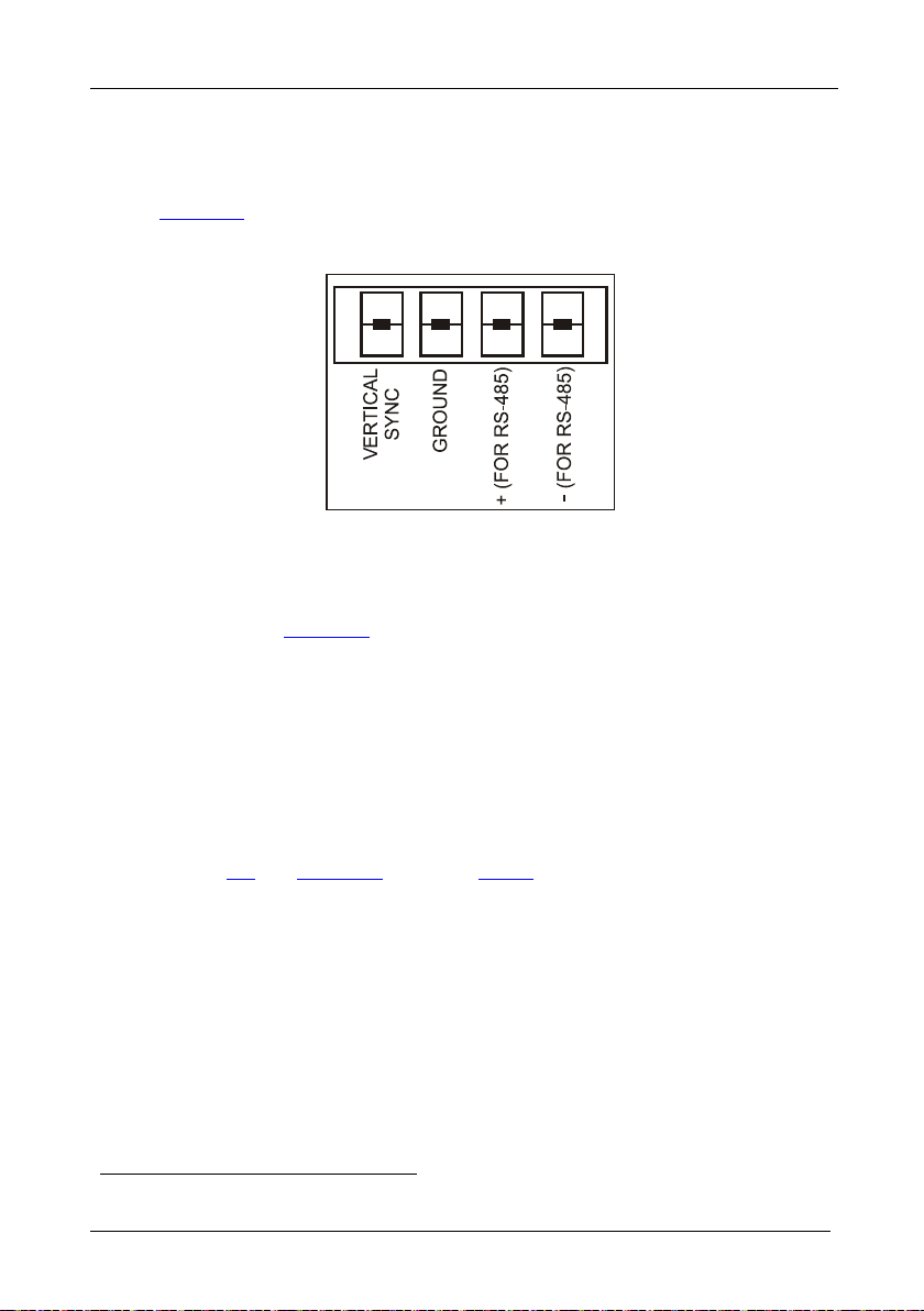
9.2 Connecting the RS-485 Control Interface
Figure 15 defines the RS-485 connector pinout for external RS-485 control.
The RS-485 connector is also used (if required) for vertical sync:
Figure 15: RS-485 Conne c tor P INOUT
To connect an RS-485 connector on one VS-162V unit to an RS-485
connector on one or more other switchers (from the series of 16x16 matrix
switchers), as
Figure 16 illustrates:
1. Connect the “+” PIN on the first VS-162V unit to the “+” PIN on the
second VS-162V unit or other unit
2. Connect the “-” PIN on the first VS-162V unit to the “-” PIN on the second
VS-162V unit or other unit
3. If shielded cable is used for an RS-485 connection, connect the shield to the
Ground PIN.
For details about how to configure the vertical sync (if required), refer to
section
1 See section 8
9.3 and Figure 21 in section 11.5.1.
Page 31

Connecting a Control Interface
27 27
Figure 16: Connecting the RS-485 Connect or s be tw e e n Two VS-162V Units
Figure 17 illustrates the RS-485 line that connects:
• Between each VS-162V unit
• To the PC via a Kramer Tools VP-43xl Interface Converter
(connect the 9-pin D-sub PC COM port to the “RS-232 in” 9-pin
D-sub port on the VP-43xl. Next, connect the RS-485 port on the
VP-43xl to the RS-485 ports on the VS-162V units)
Page 32

KRAMER: SIMPLE CREATIVE TECHNOLOGY
Connecting a Control Interface
28
Figure 17: An RS-485 Control Interface Setup
Page 33

Connecting a Control Interface
29 29
9.3 Configuring the Sync
On the VS-162V, you can s elect one of the following, as the sync input:
• EXTERNAL (“sync in” BNC connector)
• INPUT # 1 BNC connector
• MTX (Sync from Matrix) RS-485 terminal block connector, when
using multiple machines
Configure the sync via the SWITCHING METHOD menu command
2
setting
. When setting up multiple machines (for example, a 48x64
1
switcher) or a 16x16 YUV switcher, linking a common sync to all the
machines may be necessary to facilitate simultaneous vertical interval
switching.
Usually, the easiest method is to choose the sync source from the first
machine (for example, the Y unit in a 16x16 YUV switcher configuration,
as section
connectors, as
7.2.2 describes) and then connect all the terminal block
Figure 7 illustrates.
In this case, set the first machine to select the sync source from the external
sync connector or from the INPUT # 1 connector. This sync is now
available to the other machines via the RS-485 terminal block connector, as
Figure 15 and Figure 16 illustrate. Select the MTX sync on the other
machines that receive that sync.
9.4 Connecting the KEYBOARD EXTENSION
Connecting dry contact-closure switches to the Keyboard Extension (EXT.
KEYS) connector enables you to route an input to an output by remote
control from a distance of up to 1000 meters. These IN and OUT keys are
expandable
3
Figure 18. shows how to connect the Keyboard Extension
(EXT. KEYS):
1 Refer to section 11.5.1
2 Refer to section
3 Add an unlimited nu mber of push buttons to the existing keys (in parallel) by attach ing one end of the push button to the
corresponding number and the other end to the IN or OUT
11.5
Page 34

KRAMER: SIMPLE CREATIVE TECHNOLOGY
Operating Your Vi de o Ma t r ix Switcher
30
Figure 18: Keyboard Extension (EXT. KEYS) Connector
To use the Keyboard E xt ension, activate the extended KEYBOARD setting
Menu command, as section
11.6 describes.
10 Operating Your Video Matrix Switcher
You can operate your VS-162V using:
• The front panel buttons (as this section describes)
• RS-232 or RS-485 serial commands transmitted by a touch screen
system, PC
• The Kramer RC-IR2 Infrared Remote Control Transmitter
• Dry contact-closure switches connected to the keyboard extension
1
, or other serial controller
10.1 Startup Display
After switc hing on the power, the MATRIX and STATUS
following sc reens in sequence:
1 For instructions on using Kramer Windows 95/98/NT TM Control Software, refer to the separate user manual (included on
the CD-ROM in .pdf format), Kramer Control Software
2 Version 1.5 is shown in the Status Display as an example; text in the Matrix Display may vary (according to machine
settings)
2
displays show the
Page 35

Operating Your Vi de o Ma t r ix Switcher
31 31
Figure 19: Default Startup Status Display Sequence
10.2 Using the Front Panel Buttons
You can switch (see section
10.4) and clear (see section 10.5):
• One input to one output
• Several inputs to several outputs
• One input to all outputs
Choose to work in the AT ONCE mode or the CONFIRM mode:
1
In the AT ONCE (default
) mode:
• Actions require no user confirmation
• Execution is immediate
• No protection is offered against changing an action in error
In the CONFIRM mode
2
:
• You have an optional method to help avoid making a mistake
• Every action requires user confirmation
• Execution is d elayed
3
until the user confirms the action
• Protection is offered to prevent erroneous switching
• You can key-in s everal actions and then confir m t hem by pressing
the TAKE button once, to simultaneously switch several monitor s
1 For all actions except storing/recalling setups
2 The CONFIRM mode is the default for storing/recalling setups (see section
3 Failure to press the TAKE button within 30 seconds to one minute (the Timeout) will abort the action
10.6)
Page 36

KRAMER: SIMPLE CREATIVE TECHNOLOGY
Operating Your Vi de o Ma t r ix Switcher
32
10.3 Toggling Between the AT ONCE and CONFIRM Modes
To toggle between the AT ONCE (default) mode and the CONFIRM mode,
press the T AK E button.
In CONFIRM mode: Actions require user confirmation and the TAKE LED
lights.
In AT ONCE mode: Actio ns do not re quire user confirmation and the
TAKE LED does not light.
When the T AK E LED flashes:
• You cannot toggle between the AT ONCE and CONFIRM modes
• You can execute the previous action, by pressing the TAKE
button
• You can cance l the previous action, by pressing a non-relevant
button (for example, the MENU button)
10.4 Switching
You can switch:
• One input to one output (see section
• Several inputs to several outputs (see section
• One input to all outputs (see section
10.4.1)
10.4.2)
10.4.3)
10.4.1 Switching One Input to One Output
Pressing an OUT-IN combination when your VS-162V operates in the AT
ONCE mode implements the switch immediately.
To switch one input to one output (AT ONCE mode):
1. Press the appropriate OUT button.
The MATRIX display shows the two flashing digits, representing the
present input number connected to that specific output
output is clear, the two flashing digits 00 appear in the MATRIX display.
The STATUS Display shows the message:
Where x is the output number
2. Press the appropriate IN button.
The output sw itches t o the input an d th e MATRIX display shows the Input
# instead of the flashing digits.
The STATUS Display momentarily sh ows the message:
1 For example, pressing OUT button 9 shows the flashing digits 01 if input 1 was previously routed to OUT 9
out # x
1
. If the present
Page 37

Operating Your Vi de o Ma t r ix Switcher
33 33
out # x
from in # y
Where x is the output number and y is the input number
Pressing an OUT-IN combination when your VS-162V operates in the
CONFIRM mode (and the TAKE LED is li t), requires user confirmation.
To switch one input to one output (CONFIRM mode):
1. Repeat step 1 above.
2. Press the appropriate IN button.
The MATRIX display shows the two flashing digits, representing the input
number and the TAKE LED flashes.
The STATUS Display shows
1
the message:
out # x
from in # y
Where x is the output number and y is the input number
3. Press the TAKE button to confirm the action.
The output sw itches t o the input an d th e TAKE LED l ights .
10.4.2 Switching Several Inputs to Several Outputs
In the AT ONCE mode, you need to execute each OUT-IN combination
separately (see section
10.4.1). When switchi ng many inp uts to many
outputs it is recommended to toggle to the CONFIRM mode.
In the CONFIRM mode you can key-in several actions and then confirm
them by pres s ing the TAKE button once (simultaneously switching s everal
inputs to seve r a l outputs).
To switch several input s t o several outputs in t he CONFIRM mode (the
TAKE LED is lit), do the following:
1. Press the appropriate OUT button.
The MATRIX display shows the two flashing digits, representing the
previous input number for that specific output
2
. If the previous input is clear,
the two flashing digits 00 appear in the MATRIX display.
The STATUS Display shows the message:
out # x
Where x is the output number
1 Continuously, within the limit of the timeout (approximately 30 seconds to one minute)
2 For example, pressing OUT button 9 shows the flashing digits 01 if input 1 was previously routed to OUT 9
Page 38

KRAMER: SIMPLE CREATIVE TECHNOLOGY
Operating Your Vi de o Ma t r ix Switcher
34
2. Press the appropriate IN button.
The MATRIX display shows the two flashing digits, representing the input
number and the TAKE LED flashes.
The STATUS Display shows
1
the message:
out # x
from in # y
Where x is the output number and y is the input number
3. Press the second appropriate OUT button, repeating step 1 above.
4. Press the appropriate
2
IN button, repeating step 2 above.
5. Continue with th is OU T-IN button sequence, pressing the appropriate
OUT and IN buttons, as required. You can also combine an OUT-OFF
or OFF-OUT combination w ith this sequ ence.
6. After completing the sequence, press the TAKE button to confirm the
actions.
The inputs switch to the res pective out puts, as the MATRIX display shows
(no digits flash) and the TAKE LED lights.
10.4.3 Switching One Input to All Outputs
To switch one input to all the output s (in the AT ONCE mode):
1. Press the ALL button.
The MATRIX display shows all the s ets of two flashing digits (each
representing the present input number for that respective output) flashing
simultaneously.
The STATUS Display shows the message:
all OUTs
2. Press the appropriate IN button.
This input sw itches t o all the outpu ts an d th e MATRIX display shows the
identical non-flashing two digits (representing that input number).
To switch one input to all the output s (in the CONFIRM mod e, (the
TAKE LED is lit)):
1. Repeat steps 1 and 2 above.
The TAKE LED flashes.
2. Press the TAKE button to confirm the action.
The selected in put sw itches t o all th e outputs and the TAKE L ED l ights.
The MATRIX display shows the identical two non-flashing digits
(representing that input number) for all outputs.
1 Continuously, within the limit of the timeout (approximately 30 seconds to one minute)
2 That corresponds with the second OUT button
Page 39

Operating Your Vi de o Ma t r ix Switcher
35 35
10.5 Clearing
1
You can clear (delete):
• One output (see section
10.5.1)
• Several outputs (see section
• All outputs (see section
10.5.1 Clearing an Output
10.5.3)
To clear a n output (in the AT ONCE mod e):
1. Press the appropriate OUT button.
The MATRIX display shows the two flashing digits, representing the
present input number for that specific output
the two flashing digits 00 appear in the MATRIX display.
The STATUS Display shows the message:
out # x
Where x is the output number
2. Press the OFF button
3
.
The input is cl ear ed and th e MATRIX display does not show any Input # in
its place.
The STATUS Display momentarily shows the message:
out # x
reset
Where x is the output number
10.5.2)
2
. If the present input is clear,
To clear an output (in the CONFIRM mode ( the TAKE LED is lit)):
1. Repeat step 1 above.
3
2. Press the OFF button
.
The MATRIX display shows the two flashing digits 00 instead of the
previous two flashing digits and the TAKE LED flashes.
The STATUS Display shows
4
the message:
out # x
reset
Where x is the output number
1 “Clearing” means disconnecting the output from any of the inputs, and leaving it disconnected
2 For example, pressing OUT button 9 shows the flashing digits 01 if input 1 was previously routed to OUT 9
3 You can press the OFF button first, and then an OUT button (the order is irrelevant)
4 Continuously, within the limit of the timeout (approximately 30 seconds to one minute)
Page 40

KRAMER: SIMPLE CREATIVE TECHNOLOGY
Operating Your Video Matrix Sw i tc he r
36
3. Press the TAKE button to confirm the action.
The input is cleared and the TAKE LED lights. The MATRIX display does
not show any Input # in its place.
10.5.2 Clearing Several Outputs
To clear several outputs (in the AT ONCE mode):
1. Press the appropriate OUT button.
The MATRIX display shows the two flashing digits, representing the
present input number for that specific output
1
. If the present output is cle ar,
the two flashing digits 00 appear in the MATRIX display.
The STATUS Display shows the message:
out # x
Where x is the output number
2. Press the OFF butt on .
The output is cleared and the MATRIX display does not show any Input #
in its place.
The STATUS Display momentarily shows the message:
out # x
reset
Where x is the output number
To clear several outputs (in the CONFIRM mode (the TAKE LED is lit)):
1. Repeat step 1 above.
2. Press the OFF button.
The MATRIX display shows the two flashing digits 00 instead of the
previous two flashing digits and the TAKE LED flashes.
The STATUS Display shows
1
the message:
out # x
reset
Where x is the output number
3. Press the second appropriate OUT button, by repeating step 1 above.
4. Repeat step 2 above.
5. Continue with th is OU T-OFF button sequence, pressing the appropriate
OUT buttons and the OFF, as required.
The MATRIX display shows the sets of two flashing digits, representing the
present input number for each specific output.
1 For example, pressing OUT button 9 shows the flashing digits 01 if input 1 was previously routed to OUT 9
Page 41

Operating Your Vi de o Ma t r ix Switcher
37 37
6. After completing the sequence, press the TAKE button to confirm the
actions.
The inputs are cleared and the TAKE LED lights. The MATRIX display
does not show any Input # in its place.
10.5.3 Clearing All Outputs
To clear all outputs (in the AT ONCE mode):
1. Press the ALL button.
The MATRIX display shows all the s ets of two flashing digits (each
representing the present input number connected to that respective output)
flashing simultaneously.
The STATUS Display shows the message:
all OUTs
1
2. Press the OFF button
.
All the outputs are cleared and the MATRIX display momentarily shows
the message:
Reset ALL connections
!!!!
To switch one input to all the output s (in the CONFIRM mod e (the TAKE
LED is lit)):
1. Repeat step 1 above.
1
2. Press the OFF button
.
The TAKE LED flashes and the MATRIX display shows the message:
Reset ALL ?
Press TAKE to ex ecute
3. Press the TAKE button to confirm.
All the outputs are cleared and the TAKE LED lights.
10.6 Storing and Recalling Setups
You can store up to 99 settings in the non-volatile memory with the ability
to recall each of those settings.
10.6.1 Storing Setups
To store a setting, do the following:
1. Press the STO button.
The displays show the messages:
1 You can press the OFF button first, and then the ALL button (the order is irrelevant)
Page 42

KRAMER: SIMPLE CREATIVE TECHNOLOGY
Operating Your Vi de o Ma t r ix Switcher
38
Enter SETUP number
use two digit # 01-99
Store
# xy
Where xy are the OUT buttons.
2. Press two OUT buttons, using the OUTkeys # 1 to 9, and 10 (for 0).
The OUTkey s f uncti on on a decim al -basis, an d not on a pos iti onal -basis.
For example, to enter the # 14, press # 1 followe d by # 4 (not # 14). To enter
the # 3, press # 10 followed by # 3
1
.
The TAKE LED flashes and The displays show the messages:
STORE this SETUP ?
YES -> TAKE
Store
# xy
3. Press the TAKE button.
The memory stores the setup and the MATRIX display shows the message:
Setup # xy stored
Note, saving a setup to an already allocated setup #, prompts the message in
the MATRIX display:
Setup already exists
Press TAKE to overwrite
Pressing the TAKE button replaces the stored setup with the current setup.
Alternatively, press a different OUT button to change the setup #.
10.6.2 Recalling Setups
To recall a setting, do the following:
1. Press the RCL button.
The displays show the messages:
Enter SETUP number
use two digit # 01-99
RECALL
# xy
Where xy are the OUT buttons.
2. Press the appropriate two OUT buttons, using the OUTkeys # 1 to 9, and 10
(for 0). The OUTkeys function on a decimal-basis, and not on a positionalbasis. For example, to enter the # 14, press # 1 followed by # 4 (not # 14).
To enter the # 3, press # 10 f oll owed by # 3
2
.
The memory recalls the setup. The MATRIX display shows the flashing
setup and the TAKE LED flashes. The STATUS Display shows the
message:
1 However, pressing # 3 followed by the TAKE button will also enter the # 3
2 However, pressing # 3 followed by the TAKE button will also enter the # 3
Page 43

MENU Commands
39 39
SETUP # xy
Load ?
Where xy are the OUT buttons.
3. Preview the setup to decide whether to implement it. If not, you can scan the
other setups, by pressing different OUT buttons. To stop previewing the
setups, press a non-relevant butto n, s uch as an IN button.
4. Press the TAKE button.
The specific setup is implem ented.
1
If trying to recall an empty setup
, the MATRIX display would show a
message saying that that particular setup is empty and would return you to
step 1 above.
11 MENU Commands
You can pres s the MENU button up to 13 times in straight sequence to scan
the range of commands.
1 That is, a setup # for which no setup is actually stored
Page 44

KRAMER: SIMPLE CREATIVE TECHNOLOGY
MENU Commands
40
Operat ional Cont r ol
Setup Commands
Review the cur r ent set up by
pressing the TAKE button
several times (as required).
Pressing the TAKE button
lets you see how a command
is setup without changing it
Change the current st ate by
pressing the TAKE button
LOCK fron t pan el ?
ye s -> TAKE, next -> MENU
Follow the SYSTEM
ye s -> TAKE, next -> MENU
VIDEO FORMAT setting
ye s -> TAKE, next -> MENU
MACHINE ADDRESS se tting
ye s -> TAKE, next -> MENU
SWITCHING METHOD setting
ye s -> TAKE, next -> MENU
ext ended KEYBOARD set t in g
ye s -> TAKE, next -> MENU
STORE/RECALL setting
ye s -> TAKE, next -> MENU
what to INDICATE
ye s -> TAKE, next -> MENU
COMMUNICATION setting
ye s -> TAKE, next -> MENU
IR REMOTE setting
ye s -> TAKE, next -> MENU
AUTO store current SETUP
ye s -> TAKE, next -> MENU
identify MACH INE
ye s -> TAKE, next -> MENU
init ial RESET
ye s -> TAKE, next -> MENU
You can stop changing a setup at any time by pressing any IN button.
Figure 20: Sequence of MENU Commands
Page 45

MENU Commands
41 41
yes -> TAKE, next -> MENU
11.1 Locking and Unlocking the Front Panel
To prevent changing the settings accidenta lly or tampering with t he unit via
the front panel buttons, lock
1
your VS-162V. Unlocking releases the
protection mechanism.
• To lock the VS-162V:
1. Press the MENU button once.
The MATRIX display shows the message:
LOCK front panel ?
2. Press the TAKE button.
The front panel locks and the Displays momentarily show the messages:
Front panel LOCKED
to unlock- press MENU
2
Pressing a front panel button has no effect
Keyboard LOCKED
4
but remote RS-232 and RS-485
3
commands function and show on the MATRIX display.
• To unlock the VS-162V:
Either:
1. Press the MENU button.
The MATRIX display shows the message:
to UNLOCK front panel
press TAKE
The TAKE LED flashes.
2. Press the TAKE button.
The front panel unlocks
5 2
and the MATRIX display momentarily shows the
message:
Front panel
UNLOCKED
1. Press the TAKE button twice.
The front panel unlocks and the same messages show as in steps 1 and 2
above.
1 Nevertheless, even though the front panel is locked you can still operate via RS-232 or RS-485 serial (remote controller or PC)
2 After a few seconds, the status of the unit replaces this message
3 This message appears continuously in the STATUS Display, until the front panel is unlocked
4 IR and Keyboard Extension (EXT. KEYS) commands are also blocked
5 Switching the power off and on again also unlocks the front panel
Or:
Page 46

KRAMER: SIMPLE CREATIVE TECHNOLOGY
MENU Commands
42
Press TAKE to ex ecute
breakaway
11.2 Choosing the Follow or Breakaway from System Mode
The terms audio-follow-video
1
and audio breakaway
2
are well known.
Sometimes signals other than audio signals need to switch simultaneously
and at other times, need to switch independently. For example:
• Non-linear editing systems, that sometimes combine video with
analog audio and at other times combine video with digital audio
• Duplication systems, that make Master tapes from programs with
different formats: composite a nalog, component analog and
component digital
When the VS-162V funct ions in the:
• Follow-SYSTEM mode, the VS-162V switches with other 16x16
matrix switchers
• Breakaway-from-SYSTEM mode, the VS-162V
3
, implementing the same action simultaneously
4
functions
independently, implementing an action independently of the
others
The VS-162V unit will function
one other VS-162V unit
6
5
in the Follow-SYSTEM mode if at least
is set to the Follow-SYSTEM mode and these units
interconnect via an RS-232 and/or RS-485 communication line.
To set the VS-162V unit to function in the Follow-SYSTEM mode:
1. Press the MENU button twice.
The MATRIX display shows the message:
Follow the SYSTEM
yes -> TAKE, next -> MENU
2. Press the TAKE button.
The displays show the messages:
set UNIT follow SYSTEM?
current:
3. Press the TAKE button again.
The MATRIX display momentarily sh ows th is message, followed by the
1 Video and the audio channels switch simultaneously in the same way
2 Audio channels switch independently from the video channels
3 16x16 matrix switchers in the sa me series, that include, for example, the VS-1616A (16x16 balanced stereo audio matrix
switcher) units and/or the VS-1616AD (16x16 digital audio matrix switcher units)
4 Also applies to a VS-1616A unit or a VS-1616AD unit
5 The VS-162V unit changes its status immediately and goes to the Follow-system mode
6 Or VS-1616A or VS-1616AD unit (as well as other 16x16 matrix switchers in the same series)
Page 47

MENU Commands
43 43
Press TAKE to ex ecute
follow SYS
status of the switch er and in th e STATUS Disp lay the let ter “S” is
displayed behind the flashing cursor:
the UNIT is set in mode
FOLLOW system
If the status of the VS-162V unit differs from that of the other unit(s), set
the VS-162V unit to the Follow-SYSTEM mode. The MATRI X display
flashes the new stat us of the switcher and the TAKE LED flashes. Pressing
the TAKE button
1
implements all the changes to t he same state as the rest of
the system p l acing the s witcher in the Follow-SYSTEM mode.
To set the VS-162V unit to function in the Breakaway-from-SYSTEM mode:
1. Press the MENU button twice.
The MATRIX display shows the message:
FOLLOW the system
yes -> TAKE, next -> MENU
2. Press the TAKE button.
The displays show the messages:
BREAKAWAY from system?
current:
3. Press the TAKE button again.
The MATRIX display shows the message:
the UNIT is set in mode
BREAKAWAY from system
11.3 Choosing the Video Format Setting
1 Pressing a different button cancels the operation and the switcher will remain in its previous state
Choose a VIDEO FORMAT settin g fr om a choice of 4 settings: CV, YC,
YUV and RGBS.
WARNING – changing the VIDEO FORMAT resets all the OUTs/INs
connections.
To choose t he VIDEO FORMAT setting:
1. Press the MENU button until you reach the VIDEO FORMAT setting
command.
The MATRIX display shows the message:
VIDEO FORMAT sett ing
yes -> TAKE, next -> MENU
Page 48

KRAMER: SIMPLE CREATIVE TECHNOLOGY
MENU Commands
44
All INs/OUTs reset
2. Press the TAKE button.
The displays show the messages:
Use OUTkey to configure
current: 1: CV
1: CV 2: YC 3: YUV 4: RGBS
3. Press the appropriate
2
OUT button # 2, 3 or 4
3
.
The MATRIX display shows the message:
Press TAKE to configure
for x
Where x is the new VIDEO FORMAT setting, either Y/C, YUV or RGBS
(At this stage, you can still configure a different video format by pressing
another OUT button). To exit the VIDEO FORMAT setting command,
press a non-relevant bu tton , such as an IN button.
4. Press the TAKE button again.
The displays show the messages:
FORMAT changed!
current: 1: x
Where x is the new VIDEO FORMAT setting, either Y/C, YUV or RGBS
11.4 Setting the MACHINE ADDRESS
Press the MENU button until you reach the Setting the M ACHINE
ADDRESS command. Choose the standalone or the large matrix setting.
You set the MACHINE AD DRESS usi ng the OUTkeys # 1 to 9, and 10 (for
0). The OUTkeys function on a decimal-basis, and not on a positional-basis.
For example, to enter the # 15, press # 1 followed by # 5 (not # 15).
1
You can change the MACHINE ADDRESS from:
• The standalone setting to a large matrix setting (see section
11.4.1)
• A large matrix setting to the standalone setting (see section
11.4.2)
• A large matrix setting to a large matrix setti ng wi th a d ifferent
MACHINE ADDRESS (see section
1 If currently configured for composite (CV)
2 Depending on the required video format
3 Pressing OUT button # 1 when the machine is already configured for composite (CV) will show the message: requested the
same format NO CHANGES made
11.4.3)
Page 49

MENU Commands
45 45
2: Large Matrix
Alone
Press TAKE to confirm
16x16
use OUTkey 1-9, 0
1
Plan your sys tem accor ding to the chart in Figure 8 before setting the
MACHINE ADDRESS, because in a matrix configuration you need to enter
the highest MACHINE ADDRESS as well as the MACHINE ADDRESS.
11.4.1 Changing the Standalone MACHINE ADDRESS to a Large Matrix
To set the MACHINE ADDRESS:
1. Press the MENU button until you reach the MACHINE ADDRESS
command.
The MATRIX display shows the message:
MACHINE ADDRES S
setting yes -> TAKE, next -> MENU
2. Press the TAKE button.
The displays show the messages:
OUTkey 1: Stand-Alone UNIT
Current
1
3. Press the OUT button # 2.
The TAKE LED flashes and The displays show the messages:
Change to the LARGE MATRIX ?
Current
2
4. Press the TAKE button again.
The displays show the messages:
READY to set MACHINE ADDRESS
Current #
5. Enter the MACHINE ADDRESS by pressing an OUT button # 1-9, 0.
The STATUS Display shows the message:
current:
x
Where x is the OUT button # pressed
6. Press the TAKE button again.
The displays show the messages:
READY to change MAC H. ADDR.
Press TAKE to confirm
At this stage, you can enter another MACHINE ADDRESS by pressing another
OUT button.
1 Indicating that the machine is not set to the large matrix setting
2 For example, if currently configured for standalone
From # 01
to # x
Page 50

KRAMER: SIMPLE CREATIVE TECHNOLOGY
MENU Commands
46
use OUTkey 1-9, 0
x
2: Large Matrix
Matrix
7. Press the TAKE button again.
The displays show the messages:
MACHINE ADDRES S
changed
current #
x
After a few seconds, The displays show the messages:
SET highest MACHI NE ADDRESS
current #
8. Press an OUT button # 1-9, 0.
The STATUS Display shows the message:
current #
x
Where x is the OUT button # pressed
At this stage, you can enter another highest MACHINE ADDRESS. The unit
may suggest a highest MACHINE ADDRESS for your system. If so, it is
recommended that you use that address.
9. Press the TAKE button again.
The MATRIX display shows the message:
Change highest MACH. ADDR. ?
Press TAKE to confirm
10. Press the TAKE button again.
The MATRIX display shows the message:
HIGHEST MACHINE ADDRESS
Changed
11.4.2 Changing the Large Matrix MACHINE ADDRESS to Standalone
To set the MACHINE ADDRESS:
1. Press the MENU button until you reach the MACHINE ADDRESS
command.
The MATRIX display shows the message:
setting yes -> TAKE, next -> MENU
2. Press the TAKE button.
The displays show the messages:
OUTkey 1: Stand-Alone UNIT
1 Indicating that the machine is not set to standalone
MACHINE ADDRES S
Current
1
Page 51

MENU Commands
47 47
Press TAKE to confirm
to #0x
3. Press the OUT button # 1.
The displays show the messages:
STAND ALONE UNIT ( Mach# 01) ?
Press TAKE to confirm
Current
Matrix
4. Press the TAKE button again.
The MATRIX display shows the message:
MACHINE ADDRESS ch anged
now STAND-ALONE
11.4.3 Changing to a Different Large Matrix MACHINE ADDRESS
To set the MACHINE ADDRESS:
1. Press the MENU button until you reach the MACHINE ADDRESS
command.
The MATRIX display shows the message:
MACHINE ADDRES S s ettin g
yes -> TAKE, next -> MENU
2. Press the TAKE button.
The displays show the messages:
OUTkey 1: Stand-Alone UNIT
2: Large Matrix
Current
Matrix
3. Press the OUT button # 2.
The displays show the messages:
set NEW matrix
new -> TAKE leave old -> MENU
current:
16x32
4. Press the TAKE button again.
The displays show the messages:
READY to set MACHINE ADDRESS
use OUTkey 1-9, 0
current #
1
5. Press an OUT button # 1-9, 0.
The STATUS Display shows the message:
current: x
Where x is the OUT button # pressed
6. Press the TAKE button again.
The TAKE LED flashes and The displays show the messages:
READY to change MAC H. ADDR.
from # 01
Page 52

KRAMER: SIMPLE CREATIVE TECHNOLOGY
MENU Commands
48
use OUTkey 1-9, 0
x
7. Press the TAKE button again.
The displays show the messages:
MACHINE ADDRES S
changed
After a few seconds, The displays show the messages:
SET highest MACHI NE ADDRESS
8. Press an OUT button # 1-9, 0.
The STATUS Display shows the message:
current:
x
Where x is the OUT button # pressed
9. Press the TAKE button again.
The MATRIX display shows the message:
Change highest MACH. ADDR. ?
Press TAKE to confirm
10. Press the TAKE button again.
The MATRIX display shows the message:
HIGHEST MACHINE ADDRESS
Changed
current #
x
current #
11.5 Choosing the SWITCHING METHOD Setting
Section
11.5.1 describes the SWITCHING METHOD settings for
standalone units and large matrices. Section
configure a SWITCHING METHOD.
11.5.1 Understanding the SWITCHING METHOD Settings
Setting the VS-162V unit as a S tand-Alone UNIT
three SWITCHING METHOD settings:
• NoVIS - switching occurs immediately after completion of front
panel or dry-contact operation or immediately after receiving an
RS-232 or RS-485 command, or an IR command. The switching
is independent of the vertical reference
• EXT (external s ync ) - switching occurs during the vertic al
interval of the video reference signal connected to the IN SYNC
1 Via the MACHINE ADDRESS setting (as section 11.4 describes)
Figure 1
2 Item 1 in
11.5.2 describes how to
1
provides a choice of
2
Page 53

MENU Commands
49 49
connector (this signal should be properly terminated via the
TERM button
1
)
• INT# 1 (internal sync) - s witching occ urs during the vertical
interval of the video reference signal connected to IN # 1
1
Setting the VS-162V unit as a Large Matrix
(instead of as a Stand-Alone
UNIT) provides a choice of 4 SWITCHING METHOD settings:
• NoVIS, EXT or INT# 1 (as described above)
• MTX (SYNC from Matrix) - the vertical interval of the video
reference (selected on one unit in the Large Matrix system) is
present on the “SYNC” RS-485 terminal block connector
2
. This
reference signal applies to all switchers in the multi- switcher
system and facilitates switching all VS-162V units simultaneousl y
To choose the MTX (SYNC from Matrix) setting
• Connect the RS-485 terminal block connectors
3
4
between each
Figure 21 as shown in :
switcher in the multi- switcher system
• Connect and set the video reference signal on one of the video
units to EXT (external sync) or INT# 1 (interna l sync)
• Set the video reference on the o ther video units to the MTX
(SYNC from Matrix) setting
Figure 21: Choosing the MTX (SYNC from Matrix) Setting
1 Item 3 in Figure 1
Figure 1
2 Item 5 in
3 This sets the matrix sync configuration from another (Master) machine
4 Via a straight connection of all 4 PINS
Page 54

KRAMER: SIMPLE CREATIVE TECHNOLOGY
MENU Commands
50
changed
From In #1
2: External keys ON
X-key ON
11.5.2 Configuring a SWITCHING METHOD
To choose a SWITCHING METHOD setting, do the following:
1. Press the MENU button until you reach the SWITCHING METHOD
setting.
The MATRIX display shows the message:
SWITCHING METHOD setting
yes -> TAKE, next -> MENU
2. Press the TAKE button.
The displays show the messages:
Use OUTkey to configure
1: noVIS 2: EXT 3: INT#1 4:MTX
Current
External
3. Press an OUT butt on from 1, 2, 3 or 4. For exam ple, OUT button # 3 to set
the internal sync configuration.
The TAKE LED flashes and the MATRIX display shows the message:
Press TAKE to configure
from INTERNAL (Input #1)
4. Press the TAKE button.
The displays show the messages:
SWITCHING METHOD
current:
1
11.6 Choosing the Extended Keyboard Setting
Section
9.4 describes how to connect a remote unit. Activate or deactivate it
by setting the extended Keyboard setting ON or OFF.
To set the extended KEY BOARD mode , do the following:
1. Press the MENU button until reaching the extended Keyboard setting.
The MATRIX display shows the message:
2. Press the TAKE button.
The displays show the messages:
Outkey 1: External keys OFF
1 Indicating that the machine is currently set to the external switching method setting
2 Indicating that the external keys are currently activated
extended KEYBOARD setting
yes -> TAKE, next -> MENU
current:
2
Page 55

MENU Commands
51 51
changed
At once
3. Press the OUT button 1 to deactivate the External keys.
The TAKE LED flashes and the displays show the messages:
Turn OFF ex tern al k eys?
Press TAKE to ex ecute
current:
X-key ON
4. Press the TAKE button.
The displays show the messages:
External Keyboard mode
changed
current:
X-key OFF
11.7 Setting the STORE/RECALL KEYBOARD Mode
Choose one of these STORE/REC ALL KEYBOARD modes:
• At ONCE mode in which setups are stored/recalled immediately
without the need for user confirmation
• CONFIRM mode in which storing/recalling setups require user
confirmation. The CONFIRM mode is the default
1
for
storing/recalling setups and is recommended to prevent
erroneously storing/recalling of setups
To set the STORE/RECALL KEYBOARD mode to the AT ONCE mode,
instead of the CONFIRM (default) mode, do the following:
1. Press the MENU button until reaching th e STORE/RECA LL setting.
The MATRIX display shows the message:
STORE/RECALL setting
yes -> TAKE, next -> MENU
2. Press the TAKE button and choose the appropriate Outkey 1 for the AT
ONCE mode (Outkey 2 is for the CONFIRM mode).
The displays show the messages:
STO/RCL mode
current:
11.8 Choosing the INDICATE Setting
Choose what is displayed during regular operation: between scrolling the
switcher setup as
1 The AT ONCE mode is the default for all actions except storing/recalling setups
2 Useful in an expanded matrix configuration
Figure 22 illust rates, and showing the IN/OUT range
2
.
Page 56

KRAMER: SIMPLE CREATIVE TECHNOLOGY
MENU Commands
52
1: scroll SETUP 2: OUTs/INs
OUTs/INs
Press TAKE to ex ecute
OUTs/INs
changed
SETUP
Figure 22: Choosing what to INDICATE
To scroll t he switcher setup (instead of showing the IN/OUT range), do the
following:
1. Press the MENU button until you reach the what to INDICATE command.
The MATRIX display shows the message:
what to INDI CATE
yes -> TAKE, next -> MENU
2. Press the TAKE button.
The displays show the messages:
Use OUTkey to configure
Current:
3. Press the OUT button 1.
The TAKE LED flashes and The displays show the messages:
4. Press the TAKE button.
The displays show the messages:
11.9 Choosing the COMMUNICATION Setting
Choose the response option (reply or no reply).
To choose the No Reply response option, for example, do the following:
1. Press the MENU button until you reach the COMMUNICATION setting.
The MATRIX display shows the message:
Scroll switcher setup?
display mode
COMMUNICATION setting
yes -> TAKE, next -> MENU
Current:
Current:
Page 57

MENU Commands
53 53
changed
No reply
2. Press the TAKE button.
The MATRIX display shows the message:
Use OUTkey to configure
1: REPLY 2: No Reply
3. Press the OUT button 2.
The TAKE LED flashes and The displays show the messages:
Set serial po rt No rep ly
Press TAKE to ex ecute
Current:
Reply
4. Press the TAKE button again.
The displays show the messages:
Switcher response
Current:
11.10 Setting the IR REMOTE Control
Set the IR REMOTE control to enable remote control of the VS-162V
16x16 Video Matrix Switcher, using the Kramer RC-IR2 Infrared Remote
Control Device
2
manual
1
. Refer to the RC-IR2 Infrared Remote Control Device user
Table 7, for full details. and
Table 8 summariz e th e set u p an d
operational commands.
Table 7: Summary of B as ic RC-IR2 Setups
To execute this command: Press the following keys in this sequence:
Allocate the VS-162V to Group 12
Set the MACHINE #
SHIFT + GROUP + 12
UNIT + # key
settings)
3
(according to the VS-162V DIP-switch
To enable IR REMOTE control (when set OFF), do the foll owing:
1. Press the MENU butt on un til reachin g th e IR REMO TE settin g.
The MATRIX display shows the message:
IR REMOTE setting
yes -> TAKE, next -> MENU
2. Press the TAKE button.
The displays show the messages:
Outkey 1: InfraredREMOTE OFF
2: InfraredREMOTE ON
1 After enabling the IR REMOTE control command, remotely control the VS-162V via the RC-IR2 remote control
transmitter pointed at the remote receiver on the VS-162V’s front panel (item 1 in
2 You can download it from the Internet at this URL http://www.kramerelectronics.com/manuals.html
3 For example, press UNIT + # 1 if the VS-162V is set as MACHINE # 1
Figure 1)
current:
remote OFF
Page 58

KRAMER: SIMPLE CREATIVE TECHNOLOGY
MENU Commands
54
1
2: AutoSave CURRENT setup
NO save
Press TAKE to ex ecute
NO save
changed
AutoSave
3. Press the OUT button 2.
The TAKE LED flashes and The displays show the messages:
Turn ON infrared REMOTE ?
Press TAKE to ex ecute
Current:
remote OFF
4. Press the TAKE button again.
The displays show the messages:
Infrared REMOTE mode
changed
Table 8: Summary of B as ic RC-IR2 Operations
To execute this command: Press the following keys in this sequence:
Switch an Input to an Output # key (for the output) + # key (for the input)
Store/Recall a setup
SHIFT + STO/RCL + # key (for the setup)
Current:
remote ON
11.11 Choosing the AUTO STORE Current SETUP
Choose whether or not to save the current setup automatically, that is,
whether to save the machine’s status on power down, so that it ret urns to the
same status after cycling power.
To save the current setup automatically (when set OFF), do the following:
1. Press the MENU button until you reach the AUTO Store Current SETUP
command.
The MATRIX display shows the message:
AUTO store current SETUP
yes -> TAKE, next -> MENU
2. Press the TAKE button.
The displays show the messages:
OUTkey 1: no AutoSave
current:
3. Press the OUT button 2.
The TAKE LED flashes and The displays show the messages:
Auto store C URRE NT s etup ?
4. Press the TAKE button again.
The displays show the messages:
1 For example, press # 6 followed by # 2 to switch input 2 to output 6
AUTOSAVE m ode
Current:
Current:
Page 59

MENU Commands
55 55
11.12 Identifying the MACHINE
Display essential information ( the p roduct name and version number) to
identify your machine, for example, for technical support purposes.
To identify your machine, do the following:
1. Press the MENU button until you reach the Identifying the MACHINE
command.
The MATRIX display shows the message:
identify MACHINE
yes -> TAKE, next -> MENU
2. Press the TAKE button.
The MATRIX display (as
Figure 23: Machine Identification
Figure 23 illustrates) shows the message:
11.13 Choosing the Initial RESET
1
Choose to reset the machine
2
• Current status
(reloads the current setup)
to the:
• Factory default (resets to the pre-installed factory default state
3
)
Each VS-162V unit ships in its factory default
To reset the machine, d o the following:
1. Press the MENU button until you reach the initial RESET command.
The MATRIX display shows the message:
initial RESET
yes -> TAKE, next -> MENU
2. Press the TAKE button.
The MATRIX display shows the message:
Outkey 1: Current status
2: Factory default
1 Without having to switch the power off and on
2 Sometimes called a “soft reset”
3 Each VS-162V unit ships in its factory default state that is a 16 x16 co mposite video matrix, with all setups empty and each
input connected to its corresponding output (for example, 1-to-1)
Page 60

KRAMER: SIMPLE CREATIVE TECHNOLOGY
Upgrading the Flash Memory
56
3. Press the OUT button 2, for exam ple , t o rese t to the fac t ory defaul t.
The TAKE LED flashes and The displays show the messages:
Reset to factory default
Press TAKE to ex ecute
WARNING !!!!!
4. Press the TAKE button again.
The displays show the messages:
Reset to factory default
WARNING !!!!!
confirm by pressing OUT # 7
5. Press the OUT # 7.
The machine r esets t o the fac tory default and The displays show the first
messages of the reloading progress (as
Figure 23 illustrates).
12 Upgrading the Flash Memory
The main part of the VS-162V firmware is located in FLASH
which lets you upgrade to the latest Kramer firmware version in minutes !
Download t he up-to-date file from the Internet or obtain it from your dealer.
The following example shows how to install a fi l e named ( for example)
“1616-15.hex” to the FLASH memory
The current VS-162V software version shows in the STATUS display as
Figure 19 illustrates in se c tion 10.1.
2
.
1
memory,
12.1 Connecting the PC to the RS-232 Port
Before installing the latest Kramer firmware version on a VS-162V unit,
connect:
• The COM port on your PC to the RS-232 IN port on the VS-162V
unit
When simultaneously upgrading the firmware on several VS-162V units:
• Connect the COM port on your PC to the RS-232 IN port on the
first VS-162V unit
• Connect the RS-232 OUT port on the first VS-162V unit to the
RS-232 IN port on the second VS-162V unit or another 16x16
unit
• Connect All 16x16 units that you want to upgrad e, in this way,
linking them in a daisy c hain connection
1 Electrically programmable and erasable
2 The number “15” in the file name indicates the version number “1.5”. Be sure you receive the latest version, and that it is a
“.hex” file
Page 61

Upgrading the Flash Memory
57 57
• Set DIP 7 ac cording to whether or not a null-modem is being
used
1
12.2 Upgrading the Firmware
1. Install and run the K-Sender program on your PC.
2. Open the K-Sender program.
The File COM Port Sender window opens.
3. Choose the appropriate COM port.
Be sure that “9600 Baudrate” is chosen.
Click the File button.
4. Locate the file “1616-15.hex” and click the Open button.
The filename appears in the lower part of the window (in bold script).
5. Press and hold the TAKE button while simultaneously turning on the
POWER switch on the VS-162V.
After a few se conds, foll owing th e in itial mach ine i dentif ication m essage,
the MATRIX display shows the following message:
Please,
release key TAKE
6. Release the TAKE button.
The TAKE LED flashes and the MATRIX display shows the following
message:
Update program?
Please confirm < TAKE >
7. Press the TAKE button.
The MATRIX display shows the following message:
2
YOU will lose cu rren t SETUP
Confirm < TAKE >
8. Press the TAKE button again.
The MATRIX display shows the following message:
Are you ABSOLUTELY sure?
Press TAKE to ex ecute
At this stage, and at any time previously, you can cancel the operation by
pressing any button, other than the TAKE button.
1 Refer to section 8 for full details
2 Upgrading firmware resets your VS-162V unit to the factory default. This includes erasing all setups
Page 62

KRAMER: SIMPLE CREATIVE TECHNOLOGY
Upgrading the Flash Memory
58
Σ
Σ
16608D
cables and turn ON
Σ
16608D
9. Press the TAKE button once again.
The program starts working and the TAKE LED turns off.
The MATRIX display shows the following message:
ERASE flash MEMORY
Please, wait…
10. After a few seconds the FLASH memory is erased and the MATRIX
display shows the following message:
Ready for receiving
Start transmission from PC
Note: If upgrading the firmware on more than one VS-162V unit, be
sure to perform the above steps, 5 to 9, on each VS-162V unit before
continuing.
11. From the K-Sender program of your PC, click the Send button.
The color of the Send button changes to red and numbers appear
dynamically insi de th e blu e line . Th e Dis play s on th e VS-162V show the
messages:
Transfer may tak e minutes
=080756
1
Please, wait…
12. Observe the PC monitor and the VS-162V MATRIX and STATUS Displays.
After about 30 seconds, the program installation completes, the color of the
Send button ceases to be red and the numbers inside the blue line disappear.
The Displays on the VS-162V show the messages:
Program replaced
=16608D
successfully!
13. After about 3 seconds, The displays show the messages:
Turn unit OFF, reconnect
=16608D
14. Verify that the che cksum (for exam ple, Σ=16608D) is the same on both
lines.
If not, repeat the firmware upgrade process from the beginning.
15. You have successfully replaced the previous program and upgraded to the
latest Kram er fi rmw are v ers i on.
Turn the POWER sw itch on the VS-162V off.
Reconnect the RS-232 IN and RS-232 OUT rear pane l po rt c onnec ti ons (a s
applicable).
Turn the POWER sw itch on the VS-162V on again.
Observe the new version number that shows in the STATUS Display.
1 Shows the dynamic progress upgrade of the checksum
Page 63

Technical Specifications
59 59
Go to the Menu and restore your specific settings. Prepare and store all
necessary setu ps .
13 Technical Specifications
Table 9 includes the technical specifications:
Table 9: Technical Specifications of the VS-162V Video Matrix Switcher
INPUTS:
OUTPUTS:
VIDEO BANDWIDTH: 90 MHz (-3dB)
VIDEO CROSSTALK: <-52 dB @5MHz
NON-LINEARITY <0.01%
VIDEO S/N: 70.2 dB
DIFF. GAIN: <0.01 %
DIFF. PHASE: <0.01 Deg
K-FACTOR: <0.05%
CONTROL: 38 selector switches; RS-232, RS-485, IR remote, dry keyboard extension
SWITCHING: Vertical interval
POWER SOURCE: 230V AC, 50/60 Hz, (115VAC, U.S.A.) 10VA
DIMENSIONS: 19” x 7” x 2U W, D, H, rack mountable
WEIGHT: 3.5kg (7.8lbs) approx.
ACCESSORIES: Power cord, null-modem adapter, Windows®-based Kramer control software.
OPTIONS: External IR receiver cabl e
16 composite video, or 8 s-Video, or 4 RGBS, or 5 YUV, 1 Vpp / 75Ω on BNC
connectors
16 composite video, or 8 s-Video, or 4 RGBS, or 5 YUV, 1 Vpp / 75Ω on BNC
connectors
14 Communication Protocol
Table 10 includes the Protocol 20001 hexadecimal codes
communication parameters are: 9600 baud, with no parity, 8 data bits and 1
stop bit.
1 Full details are available on our Web site: www.kramerelectronics.com
2 This example assumes MACHINE # 1, and node 0
2
. The
Page 64

KRAMER: SIMPLE CREATIVE TECHNOLOGY
Communicat ion Pr ot ocol
60
OUT
16
OUT
15
OUT
14
OUT
13
OUT
12
OUT
11
OUT
10
OUT 9 OUT 8 OUT 7 OUT 6 OUT 5 OUT 4 OUT 3 OUT 2 OUT1
IN
01
01
01
01
01
01
01
01
01
01
01
01
01
01
01
01
IN
01
81
01
81
01
81
01
81
01
81
01
81
01
81
01
81
01
81
01
81
01
81
01
81
01
81
01
81
01
81
01
81
IN
01
81
01
81
01
81
01
81
01
81
01
81
01
81
01
81
01
81
01
81
01
81
01
81
01
81
01
81
01
81
01
81
IN 4 01
81
01
81
01
81
01
81
01
81
01
81
01
81
01
81
01
81
01
81
01
81
01
81
01
81
01
81
01
81
01
81
IN
81
81
81
81
81
81
81
81
81
81
81
81
81
81
81
81
IN
01
01
01
01
01
01
01
01
01
01
01
01
01
01
01
01
IN
01
81
01
81
01
81
01
81
01
81
01
81
01
81
01
81
01
81
01
81
01
81
01
81
01
81
01
81
01
81
01
81
IN
01
81
01
81
01
81
01
81
01
81
01
81
01
81
01
81
01
81
01
81
01
81
01
81
01
81
01
81
01
81
01
81
IN
01
81
01
81
01
81
01
81
01
81
01
81
01
81
01
81
01
81
01
81
01
81
01
81
01
81
01
81
01
81
01
81
IN
81
81
81
81
81
81
81
81
81
81
81
81
81
81
81
81
IN
01
81
01
81
01
81
01
81
01
81
01
81
01
81
01
81
01
81
01
81
01
81
01
81
01
81
01
81
01
81
01
81
IN
Table 10: Hex Table for the VS-162V Video Matrix Switcher
01
01
01
01
01
01
01
01
01
01
01
01
01
01
01
01
1
2
3
81
81
81
82
81
81
83
81
84
81
81
82
81
82
82
81
83
82
84
82
81
83
81
82
83
81
83
83
84
83
81
84
81
82
84
81
83
84
84
84
81
85
81
82
85
81
83
85
84
85
81
86
81
82
86
81
83
86
84
86
81
87
81
82
87
81
83
87
84
87
81
88
81
82
88
81
83
88
84
88
81
89
81
82
89
81
83
89
84
89
81
8A
81
82
8A
81
83
8A
84
8A
81
8B
81
82
8B
81
83
8B
84
8B
81
8C
81
82
8C
81
83
8C
84
8C
81
8D
81
82
8D
81
83
8D
84
8D
81
8E
81
82
8E
81
83
8E
84
8E
81
8F
81
82
8F
81
83
8F
84
8F
81
90
81
82
90
81
83
90
84
90
IN
IN
10
11
12
IN
13
IN
14
15
16
5
6
7
8
9
85
81
01
86
81
01
87
81
81
01
88
81
81
89
81
81
8A
81
8B
81
8C
81
01
8D
81
01
8E
81
81
01
8F
81
81
90
81
85
82
01
86
82
01
87
82
81
01
88
82
81
89
82
81
8A
82
8B
82
8C
82
01
8D
82
01
8E
82
81
01
8F
82
81
90
82
85
83
01
86
83
01
87
83
81
01
88
83
81
89
83
81
8A
83
8B
83
8C
83
01
8D
83
01
8E
83
81
01
8F
83
81
90
83
85
84
01
86
84
01
87
84
81
01
88
84
81
89
84
81
8A
84
8B
84
8C
84
01
8D
84
01
8E
84
81
01
8F
84
81
90
84
8A
8B
8C
8D
8E
85
85
01
86
85
01
87
85
81
01
88
85
81
89
85
81
85
85
85
01
85
01
85
81
01
8F
85
81
90
85
85
86
01
86
86
01
87
86
81
01
88
86
81
89
86
81
8A
86
8B
86
8C
86
01
8D
86
01
8E
86
81
01
8F
86
81
90
86
85
87
01
86
87
01
87
87
81
01
88
87
81
89
87
81
8A
87
8B
87
8C
87
01
8D
87
01
8E
87
81
01
8F
87
81
90
87
85
88
01
86
88
01
87
88
81
01
88
88
81
89
88
81
8A
88
8B
88
8C
88
01
8D
88
01
8E
88
81
01
8F
88
81
90
88
85
89
01
86
89
01
87
89
81
01
88
89
81
89
89
81
8A
89
8B
89
8C
89
01
8D
89
01
8E
89
81
01
8F
89
81
90
89
85
8A
01
86
8A
01
87
8A
81
01
88
8A
81
89
8A
81
8A
8A
8B
8A
8C
8A
01
8D
8A
01
8E
8A
81
01
8F
8A
81
90
8A
85
8B
01
86
8B
01
87
8B
81
01
88
8B
81
89
8B
81
8A
8B
8B
8B
8C
8B
01
8D
8B
01
8E
8B
81
01
8F
8B
81
90
8B
85
8C
01
86
8C
01
87
8C
81
01
88
8C
81
89
8C
81
8A
8C
8B
8C
8C
8C
01
8D
8C
01
8E
8C
81
01
8F
8C
81
90
8C
85
8D
01
86
8D
01
87
8D
81
01
88
8D
81
89
8D
81
8A
8D
8B
8D
8C
8D
01
8D
8D
01
8E
8D
81
01
8F
8D
81
90
8D
85
8E
01
86
8E
01
87
8E
81
01
88
8E
81
89
8E
81
8A
8E
8B
8E
8C
8E
01
8D
8E
01
8E
8E
81
01
8F
8E
81
90
8E
85
8F
01
86
8F
01
87
8F
81
01
88
8F
81
89
8F
81
8A
8F
8B
8F
8C
8F
01
8D
8F
01
8E
8F
81
01
8F
8F
81
90
8F
85
90
01
86
90
01
87
90
81
01
88
90
81
89
90
81
8A
90
8B
90
8C
90
01
8D
90
01
8E
90
81
01
8F
90
81
90
90
Page 65

61
LIMITED WARRANTY
WHO IS PROTECTED?
WHAT IS COVERED AND WHA T IS NO T COVERED
WHAT WE WILL P A Y F OR AND WHA T WE WILL NOT P A Y FOR
HOW YOU CAN GET WARRANTY SERVICE
LIMITA TION OF IMPLIED W ARRANTIES
EXCLUSION OF DAMAGES
CAUTION!
Kramer Electronics (hereafter ) warrants this product free from defects in material and workmanship under the
following terms.
Kramer
HOW LONG IS THE WARRANTY
Labor and parts are warranted for seven years from the date of the first customer purchase.
Only the first purchase customer may enforce this warranty.
W e will pa y labor a nd mat erial ex pense s for c overed i tems. W e will n ot pay for the follo wing:
The liab ilit y of K ramer for an y ef fec tive p rod ucts is lim ite d to th e rep air or repl ace ment of the p rodu ct a t our o ptio n. Kr ame r shal l
not be li able for:
This war ranty gives y ou speci fic l egal righ ts, a nd you ma y also have oth er rig hts, w hich var y from p lace to place.
All produc ts retur ned t o Kramer f or ser vice m ust hav e prior a pprov al. Th is may b e obta ined from your deale r.
This equ ipmen t has be en teste d to de termin e compl iance w ith t he requir emen ts of:
EN-5008 1: "Electro magnet ic com patibi lity ( EMC);
generic emission standard.
Residen tial, c omme rcial an d light indus try"
EN-5008 2: "Electro magnet ic com patibi lity ( EMC) gen eric i mmunity stand ard.
Part 1: R esiden tial, commer cial an d light indus try env ironme nt".
CFR-47: FCC* Rules and Regulations:
Part 15: “Ra d io frequency devices
Subpart B Unintentional radiators”
Except as below, this warranty covers all defects in material or workmanship in this product. The following are not covered
by the warranty:
1. Any product which is not distributed by Kramer, or which is not purchased from an authorized Kramer dealer. If you are
uncertain as to whether a dealer is authorized, please contact Kramer at one of the agents listed in the Web site
www.kramerelectronics.com.
2. Any product, on which the serial number has been defaced, modified or removed, or on which the WARRANTY VOID
T AMP ER E D sti c ke r ha s be e n to r n,
3. Damage, de terior ation o r malf uncti on resu lting f rom:
i) Accident, misuse, abuse, neglect, fire, water, lightn ing or other a cts of na ture
ii) Product modi ficati on, or fa ilur e to foll ow instr ucti ons sup plied w ith the produ ct
iii) Repair o r atte mpted r epair by anyo ne not au thori zed by Kr amer
iv) Any ship ment of the pro duct (c laims m ust be pr esente d to th e carri er)
v) Remo val or i nstall ation of the pr oduct
vi) Any other cause, which does not relate to a product defect
vii)Cartons, e quipme nt encl osure s, cabl es or accesso ries use d in c onjunc tion wi th the p roduct
1. Rem oval or inst allatio ns char ges .
2. Costs of initial technical adjustments (set-up), including adjustment of user controls or programming. These costs are the
respon sibili ty of th e Krame r deal er from wh om the produ ct was pu rchas ed.
3. Shipping char ges.
1. To obtain service on you product, you must take or ship it prepaid to any authorized Kramer service center.
2. Whenever warranty service is required, the original dated invoice (or a copy) must be presented as proof of warranty
coverage, and should be included in any shipment of the product. Please also include in any mailing a contact name,
company, address, and a description of the problem(s).
3. For the name of the nearest Kramer authorized service center, consult your authorized dealer.
All implied warranties, including warranties of merchantability and fitness for a particular purpose, are limited in duration to
the length of this warranty.
1. Damage to other p roper ty cause d by defe cts in t his prod uct, damages based upo n inco nvenie nce, lo ss of use of the pro duct, loss
of time, commercial loss ; or:
2. Any other da mages , w het her i nci den tal, cons eque nti al o r o the rwise . S ome c oun tri es ma y n ot a llow lim ita tion s on ho w lon g a n
implied warranty lasts and/or do not allow the exclusion or limitation of incidental or consequential damages, so the above
limita tions a nd excl usions m ay no t apply to you.
Servicing the machines can only be done by an authorized Kramer technician. Any user who makes changes or
modifications to the unit without the expressed approval of the manufacturer will void user authority to operate the
equipment.
Use the supplie d DC powe r sup ply to f eed pow er to the mach ine.
Please use recommended interconnection cables to connect the machine to other components.
IF reattached, removed or otherwise interfered with.
* FCC and CE appro ved using S TP ca ble (f or twist ed pair pr oducts )
NOTE:
Part 1:
Page 66

For the latest information on our products and a list of Kramer
distributors, visit our Web site:
www.kramerelectronics.com,
where updates to this user manual may be found.
We welcome your questions, comments an d feedb a ck.
Safety Warning:
Disconnect the unit from the power supply before
opening/servicing.
Caution
Kramer Electronics, Ltd.
Web site: www.kramerelectronics.com
E-mail: info@kramerel.com
P/N: 2900-002065 REV 3
 Loading...