

Page 1

KRAMER ELECTRONICS LTD.
USER MANUAL
MODEL:
VS
4x2 DVI Matrix Switcher
P/N: 2900-300218 Rev 5
-42HDCP
Page 2
Page 3

Contents
1 Introduction 1
2 Getting Started 2
2.1 Achieving the Best Performance 2
2.2 Safety Instruc ti o ns 2
2.3 Recycling Kramer Products 3
3 Overview 4
3.1 About Fast Switching 5
3.2 Defining the VS-42HDCP 4x2 DVI Matrix Switcher 5
4 Installing in a Rack 8
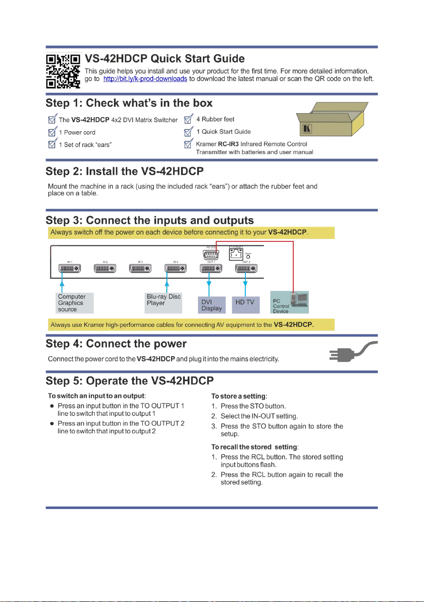
5 Connecting the VS-42HDCP 9
6 Operating the VS-42HDCP 4x2 DVI Matrix Switcher 11
6.1 Routing Inputs to Outputs 11
6.2 Disconnecting the Outputs 11
6.3 Storing and Recalling a Switching Setting 12
6.4 Changing the Port Switching Speed 13
6.5 Setting HDCP to On/Off 13
6.6 Locking and Unlocking the Front Panel 14
6.7 Switching Between Protocol 2000 and Protocol 3000 14
6.8 Acquiring the EDID 14
6.9 Resetting the IP Parameters 15
7 Controlling the VS-42HDCP 16
7.1 Connecting to the VS-42HDCP via RS-232 16
7.2 Connecting via Ethernet 16
7.3 Using the IR Transmitter 17
7.4 Firmware Upgrade 18
8 Technical Specifications 19
9 Default Communication Parameters 20
10 Default EDID 21
11 Kramer Protocol 2000 23
12 Protocol 3000 26
12.1 Kramer Protocol 3000 Syntax 26
12.2 Kramer Protocol 3000 Commands 29
12.3 Kramer Protocol 3000 – Detailed Commands 30
Figures
Figure 1: VS-42HDCP 4x2 DVI Matrix Switcher Front Panel 6
Figure 2: VS-42HDCP 4x2 DVI Matrix Switcher Rear Panel 7
Figure 3: Connecting to the VS-42HDCP Rear Panel 10
VS-42HDCP – Contents i
Page 4

1 Introduction
Welcome to Kramer Electronics! Since 1981, Kramer Electronics has been
providing a world of unique, creative, and affordable solutions to the vast range of
problems that confront video, audio, presentation, and broadcasting professionals
on a daily basis. In recent years, we have redesigned and upgraded most of our
line, making the best even better!
Our 1,000-plus different models now appear in 14 groups that are clearly defined
by function: GROUP 1: Distribution Amplifiers; GROUP 2: Switchers and Routers;
GROUP 3: Control Systems; GROUP 4: Format/Standards Converters; GROUP 5:
Range Extenders and Repeaters; GROUP 6: Specialty AV Products; GROUP 7:
Scan Converters and Scalers; GROUP 8: Cables and Connectors; GROUP 9:
Room Connectivity; GROUP 10: Accessories and Rack Adapters; GROUP 11:
Sierra Video Products; GROUP 12: Digital Signage; GROUP 13: Audio; and
GROUP 14: Collaboration.
Congratulations on purchasing your Kramer VS-42HDCP 4x2 DVI Matrix Switcher,
which is ideal for conference room presentations and advertising applications as
well as for rental and staging.
VS-42HDCP - Introduction 1
Page 5

VS-42HDCP - Getting Started
Caution:
There are no operator serviceable parts inside the unit
Warning:
Use only the power cord that is supplied with the unit
i
!
!
2 Getting Started
We recommend that you:
• Unpack the equipment carefully and save the original box and packaging
materials for possible future shipment
• Review the contents of this user manual
Go to www.kramerav.com/support/product_downloads.asp
to check for up-to-date user manuals, application programs, and to check if
firmware upgrades are available (where appropriate).
2.1 Achieving the Best Performance
To achieve the best performance:
• Use only good quality connection cables (we recommend Kramer high-
performance, high-resolution cables) to avoid interference, deterioration in
signal quality due to poor matching, and elevated noise levels (often
associated with low quality cables
• Do not secure the cables in tight bundles or roll the slack into tight coils
• Avoid interference from neighboring electric al appli ances that may adversely
influence signal quality
• Position your Kramer VS-42HDCP away from moisture, excessive sunlight
and dust
This equipment is to be used only inside a building. It may only be
connected to other equipment that is installed inside a building.
2.2 Safety Instructions
Warning:
Warning:
2
Do not open the unit. High voltages can cause
electrical shock! Servicing by qualified personnel only
Disconnect the power and unplug the unit from the wall
before installing
Page 6

2.3 Recycling Kramer Products
The Waste Electrical and Electronic Equipment (WEEE) Directive 2002/96/EC
aims to reduce the amount of WEEE sent for disposal to landfill or incineration by
requiring it to be collected and recycled. To comply with the WEEE Directive,
Kramer Electronics has made arrangements with the European Advanced
Recycling Network (EARN) and will cover any costs of treatment, recycling and
recovery of waste Kramer Electronics branded equipment on arrival at the EARN
facility. For details of Kramer’s recycling arrangements in your particular country
go to our recycling pages at www.kramerav.com/support/recycling/
.
VS-42HDCP - Getting Started 3
Page 7

VS-42HDCP - Overview
3 Overview
The VS-42HDCP is a high quality 4x2 DVI matrix switcher. It reclocks and
equalizes the signals and can route any of the four DVI/HDMI (over DVI-D
connector) inputs to one or both DVI/HDMI outputs simultaneously.
DVI-D (Digital). Note that only the digital signal (DVI D) is available on the DVI connector.
In particular, the VS-42HDCP features:
• Up to 6.75Gbps data rate (2.25Gbps per graphics channel)
Suitable for resolutions up to UXGA and 1080p at 60Hz
• Support for HDCP (High Definition Digital Content Prot ection)
• HDMI Support – HDMI (3D, Deep Color, x.v.Color™, Lip Sync)
• 3D pass-through
• Support for up to 7.1 multi-channel audio
• I-EDIDPro™ Kramer Intelligent EDID Processing™ – Intelligent EDID
handling and processing algorithm ensures Plug and Play operation for
HDMI systems
• Kramer reKlocking™ and Equalization Technology t hat rebuil ds the digital
signal to travel longer distances
• A LOCK button to prevent unwanted tampering with the buttons on the front
panel
• Support for Kramer Protocol 2000 and Protocol 3000
You can control the VS-42HDCP using the front panel buttons or remotely via:
• RS-232 serial commands transmitted by a touch screen system, PC or other
serial controller
• The Kramer RC-IR3 infrared remote control transmitter
• The infrared remote extension cable transmi tter (optional), see Section 7.3
• The Ethernet port
4
Page 8

3.1 About Fast Switching
Older display devices required a longer time between the loss of one digital signal
and the introduction of another, as well as a physical disconnection of the
interconnecting cable in order to be able to detect and adjust to the new video
attributes and parameters. Normal switching, therefore, introduced a 5V signal
disconnection along with a delay in switching. Many newer display devices,
however, are now capable of “on-the-fly” switching.
Depending on the display device in use, the VS-42HDCP allows for fast switching
(minor reset and the connection kept alive) and extra fast switching (no reset and
the connection kept alive). Using the fast and extra fast switching modes allows for
fraction-of-a-second switching times when using high performance display devices
or when using a scaler on the video output.
3.2 Defining the VS-42HDCP 4x2 DVI Matrix Switcher
This section defines the VS-42HDCP.
VS-42HDCP - Overview 5
Page 9
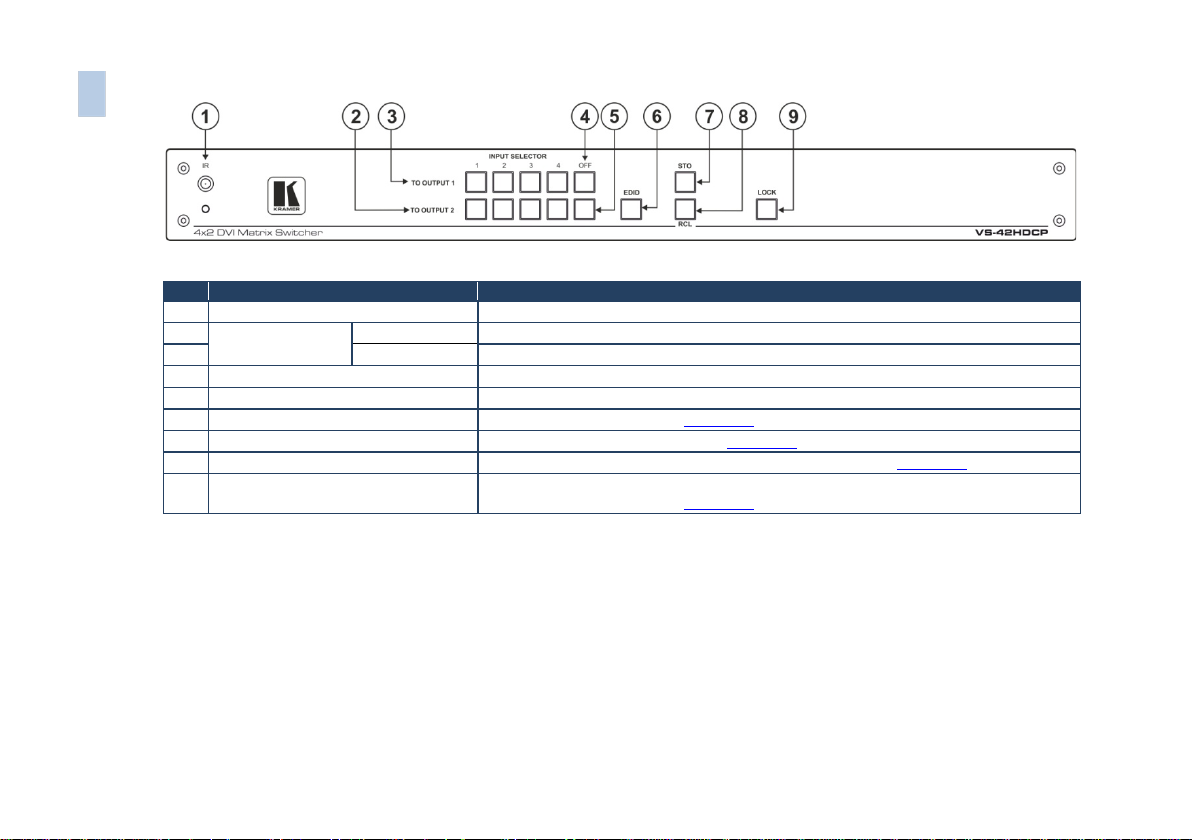
#
Feature
Function
1
IR Receiver and LED
IR remote control sensor. LED lights yellow when receiving an IR signal
3
TO OUTPUT 1
Press one of the 4 inputs to switch it to Output 1
4
OFF Button Output 1
Press to disconnect output 1 from the inputs
5
OFF Button Output 2
Press to disconnect output 2 from the inputs
6
EDID Button
Press to acquire the EDID (see Section 6.7)
8
RCL Button
Press to recall a stored switching configuration from a preset (see Section 6.3)
Press to acquire the EDID (see Section 6.7)
6 VS-42HDCP – Overview
Figure 1: VS-42HDCP 4x2 DVI Matrix Switcher Front Panel
2 INPUT SELECTOR
Buttons
7 STO Button Press to store a switching setting (see Section 6.3)
9 LOCK Button Press and hold to toggle the locking/release of the front panel buttons.
TO OUTPUT 2 Press one of the 4 inputs to switch it to Output 2
Page 10
#
Feature
Function
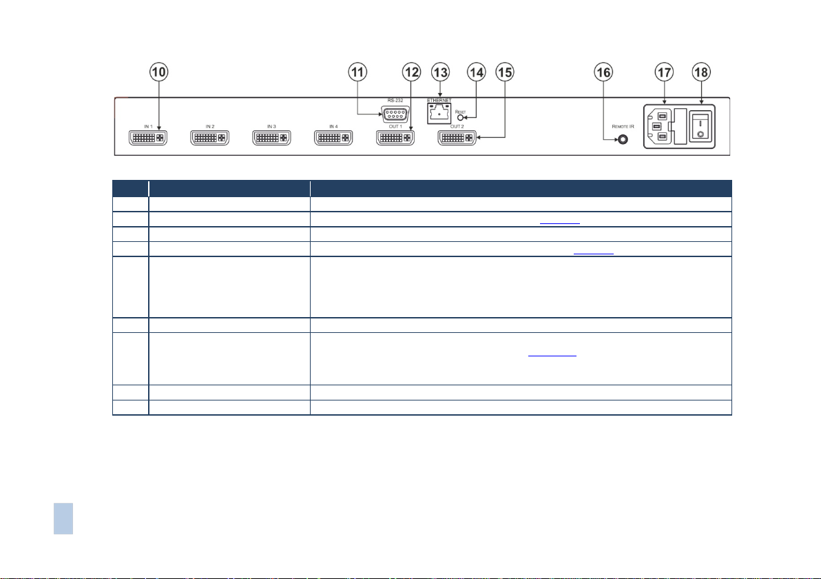
10
IN DVI Connectors
Connect to the DVI/HDMI (over DVI-D connect or ) sources (from 1 to 4)
11
RS-232 9-pin D-sub (F) Connector
Connect to a PC or the serial remote c ont roll e r (see Section 9)
12
OUT 1 DVI Connector
Connect to a DVI/HDMI acceptor
13
ETHERNET RJ-45 Connector
Connect to a PC or other Ethernet controller via a LAN (see Section 9)
erases all stored preset
15
OUT 2 DVI Connector
Connect to a DVI acceptor
16
REMOTE IR opening
Connect to an external IR receiver unit for controlling th e machi ne v ia an IR re m ote cont rol le r
17
Power Connector with Fu se
AC connector, enabling power supply to the unit
18
POWER Switch
Switch for turning the unit ON or OF F
VS-42HDCP – Overview 7
Figure 2: VS-42HDCP 4x2 DVI Mat ri x Switcher Rear Panel
14 RESET Button Press to reset to factory default definitions:
IP number − 192.168.1. 39, Mask – 255.255.0.0, Gateway – 0.0.0.0
First, disconnect the power cord and then connect it again while pressing the ETH Factory
Reset button. The unit powers up and loads its memory with the factory default definitions and
(instead of using the front panel IR receiver), see Section 7.3
Covered by a cap. The 3.5mm jack at the end of the internal IR connection cable fits into this
opening
Page 11
4 Installing in a Rack
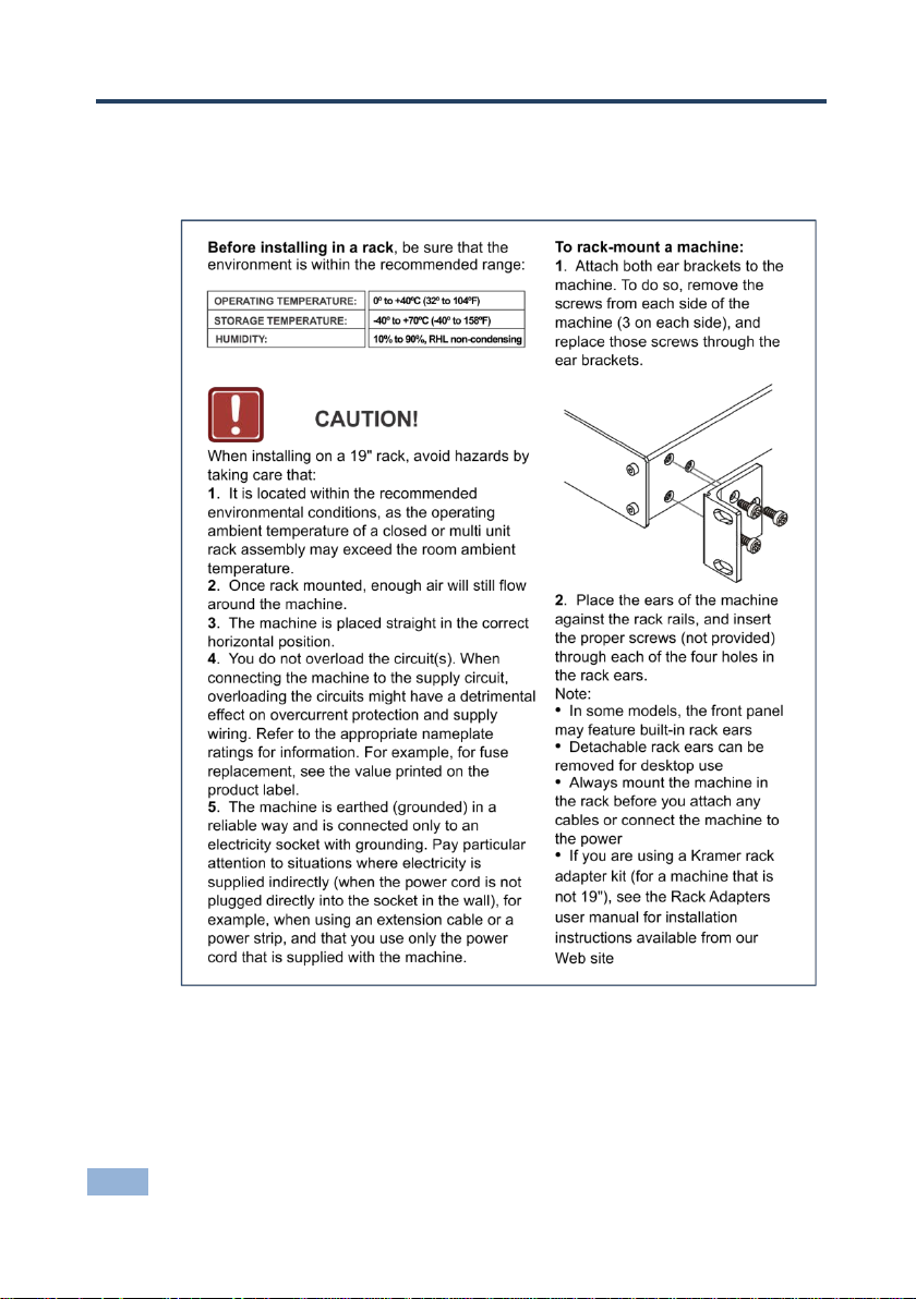
This section provides instructions for rack mounting the unit.
8 VS-42HDCP - Installing in a Rack
Page 12

i
5 Connecting the VS-42HDCP
Always switch off the power to each device before connecting it to your
VS-42HDCP. After connecting your VS-42HDCP, connect its power
and then switch on the power to each device.
To connect the VS-42HDCP as illustrated in the example in Figure 3
1. Connect up to four DVI sources (for example, DVD players and/or Blu-ray
disc players) to the IN DVI connectors.
You do not have to connect all the sources.
2. Connect the two OUT DVI connectors to up to two DVI acceptors (for
example, DVI and/or LCD displays).
You do not have to connect all the outputs.
3. If required, connect a PC and/or controller to the RS-232 port (see
Section 7.1) and/or the Ethernet port (see Section 7.2
4. Connect the power cord (not shown in Figure 3).
5. Power the device.
6. If required, acquire the EDID (see Section 6.7
).
).
:
VS-42HDCP - Connecting the VS-42HDCP 9
Page 13
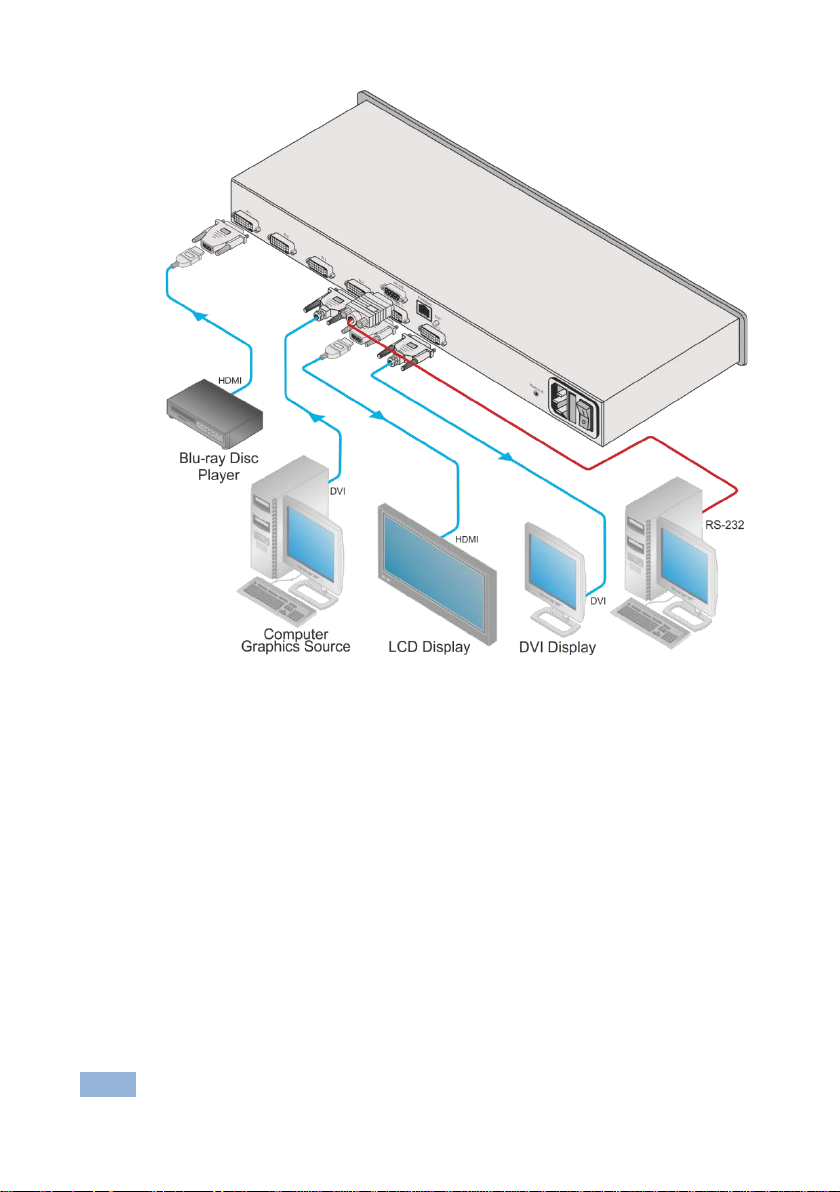
Figure 3: Connecting to the VS-42HDCP Rear Panel
10 VS-42HDCP - Connecting the VS-42HDCP
Page 14

6 Operating the VS-42HDCP 4x2 DVI Matrix
Switcher
This section describes how to:
• Switch inputs to outputs (see Section 6.1
• Disconnect outputs (see Section 6.2)
• Store and recall a setup (see Section 6.3)
• Change the port switching speed (see Section 6.4)
• Set HDCP on or off (see Section 6.5)
• Lock and unlock the front panel (see Section 6.6)
• Switch between protocol 2000 and protocol 3000 (see Section 6.7)
• Acquire the EDID (see Section 6.8)
• Reset the Ethernet configuration to default values (see Section 6.9)
6.1 Routing Inputs to Outputs
To route an input to an output:
• Press an INPUT button (from 1 to 4) in the TO OUTPUT 1 row to select an
input to switch to output 1
• Press an INPUT button (from 1 to 4) in the TO OUTPUT 2 row to select an
input to switch to output 2
6.2 Disconnecting the Outputs
)
To disconnect output 1, press the OFF button on the TO OUTPUT 1 line and to
disconnect output 2, press the OFF button on the TO OUTPUT 2 line. The OFF
button illuminates.
VS-42HDCP - Operating the VS-42HDCP 4x2 DVI Matrix Switcher 11
Page 15

i
6.3 Storing and Recalling a Switching Setting
You can use the STO and RCL buttons to store the current setup and then recall
it.
The VS-42HDCP stores only one setting in memory. Storing a new
setting overwrites the previous one.
To store a setting:
1. Press the STO button.
The STO button illuminates and the:
Currently selected input buttons illuminate
The selected Input buttons in the current configuration flash
For example, if both outputs are currently disconnected, both OFF buttons
illuminate and the current setting input buttons (for example, INPUT 1 to
OUTPUT 1 and INPUT 3 to OUTPUT 2) flash.
2. Set the machine to the desired setting.
For example, press INPUT SELECTOR button 3 on the TO OUTPUT 1 line
and INPUT SELECTOR button 1 on the TO OUTPUT 2 line.
These buttons flash
3. Press the STO button again to store the current setup (You have to press
the STO button within 10 seconds, before the store operation times-out).
The STO button no longer illuminates and the current setting is stored in the
non-volatile memory.
To recall a setup:
1. Press the RCL button.
The RCL button illuminates as well as the current setting input buttons, and
the input buttons of the stored setup flash.
2. Press the RCL button once again to recall the stored setting.
12 VS-42HDCP - Operating the VS-42HDCP 4x2 DVI Matrix Switcher
Page 16

6.4 Changing the Port Switching Speed
The switching speed can be set for both output ports to any of the following:
• Extra fast
• Fast
• Normal
To change the port switching speed:
1. Turn the power off.
2. To set the output ports’ switching speed to:
Ex-fast, press the INPUT 1 (of the TO OUTPUT 1 selector buttons)
and LOCK buttons while turning the power on
Fast, press the INPUT 2 (of the TO OUTPUT 1 selector buttons) and
LOCK buttons while turning the power on
Normal, INPUT 3 (of the TO OUTPUT 1 selector buttons) and LOCK
buttons while turning the power on
Note: If the EDID button is not pressed within about 12 seconds, the device exits
the port speed switching mode automatically and all changes are lost.
6.5 Setting HDCP to On/Off
HDCP support can be enabled (On) or disabled (Off) for each of the HDMI inputs,
allowing the source to transmit a non-HDCP signal if required (for example, when
working with a Mac computer)
To set the HDCP:
1. Turn the power off on the machine.
2. Press and hold the IN 1, IN 2 and LOCK buttons simultaneously and turn the
power on while pressing these buttons (you will need more than one person
to perform this step).
The machine is set to the HDCP enable/disable mode.
VS-42HDCP - Operating the VS-42HDCP 4x2 DVI Matrix Switcher 13
Page 17

The input front panel buttons’ status indicates the HDCP state of each input:
HDCP enabled (ON) on an input – that input button is illuminated
HDCP disabled (OFF) on an input – that button is not illuminated
3. Press an input button to change its status.
You can press one or more inputs.
4. Once you have changed the status of HDCP on the inputs as desired, press
the EDID to save the changes and exit the HDCP enable/disable mode to
return to normal operation.
Note: If the EDID button is not pressed within about 12 seconds, the device exits
the port HDCP On/Off mode automatically and all changes are lost.
6.6 Locking and Unlocking the Front Panel
To prevent unintended tampering with the unit via the front panel buttons, lock
your VS-42HDCP.
To lock/unlock the VS-42HDCP:
• Press and hold the LOCK button on the front panel for about 3 seconds
6.7 Switching Between Protocol 2000 and Protocol 3000
To switch from Protocol 2000 to Protocol 3000 and back again using the
front panel buttons:
1. On the TO OUTPUT 1 row, press input buttons 1 and 3 at the same time.
Protocol 3000 is active.
2. On the TO OUTPUT 1 row, press input buttons 1 and 2 at the same time.
Protocol 2000 is active.
6.8 Acquiring the EDID
You can acquire the EDID from OUT 1 and/or OUT 2 and copy it to any of the four
inputs, or reset to the default EDID. The EDID is acquired at once for all the
inputs, according to the status of the selector buttons.
14 VS-42HDCP - Operating the VS-42HDCP 4x2 DVI Matrix Switcher
Page 18

i
i
To acquire or change the EDID of one or both new output disp l ays:
1. Connect the required acceptor to the output from which you want to acquire
the EDID.
2. Connect the power supply.
3. Press the EDID button and hold it for 3 seconds.
The four buttons that switch to the output from which you are acquiring the
EDID show their current state:
Input buttons that do not illuminate, store the default EDID
Input buttons that flash, store the previously acquired EDID from the
OUT 1 or OUT 2 acceptor
4. For each input, select the output from which it will acquire the EDID, or
deselect it so it will reset to the default EDID value.
For example, to copy the EDID of output 2 to input 3, press the INPUT
SELECTOR button 3 on the TO OUTPUT 2 line.
5. Press the LOCK button.
The LOCK button and the INPUT buttons flash until the EDID is acquired.
Note that while reading the EDID, the displays that are connected to
the OUT 1 and OUT 2 connectors may flicker once or twice.
To reset to the default EDID:
To reset to the default EDID do either of the following:
• Disconnect the outputs and repeat the step 2 to 5 above.
• Press the input where the default EDID is to be stored to disconnect it from
the output
6.9 Resetting the IP Parameters
This procedure resets only the IP related parameters. All switching and
preset values remain unchanged.
To reset the IP parameters to their default values (see Section 9
• Press and hold the ETH Reset button on the rear panel while powering up
the device
VS-42HDCP - Operating the VS-42HDCP 4x2 DVI Matrix Switcher 15
):
Page 19

7 Controlling the VS-42HDCP
You can control the VS-42HDCP via the
• RS-232 serial commands transmitted by a touch screen system, PC or other
serial controller (see Section 7.1
• The Ethernet port (see Section 7.2)
• The Kramer infrared remote control transmitter (see separate user manual)
)
• The infrared remote extension cable transmitter (optional), see Section 7.3
7.1 Connecting to the VS-42HDCP via RS-232
You can connect to the VS-42HDCP via an RS-232 connection using, for
example, a PC. Note that a null-modem adapter/connection is not required.
To connect to the VS-42HDCP via RS-232:
• Connect the RS-232 9-pin D-sub rear panel port on the VS-42HDCP unit via a
9-wire straight cable (only pin 2 to pin 2, pin 3 to pin 3, and pin 5 to pin 5 need
to be connected) to the RS-232 9-pin D-sub port on your PC
7.2 Connecting via Ethernet
You can connect to the VS-42HDCP via Ethernet using either of the following
methods:
• Directly to the PC using a crossover cable (see Section 7.2.1
• Via a network hub, switch, or router, using a straight-through cable (see
Section 7.2.2
After connecting the VS-42HDCP to the Ethernet port, configure your local Ethernet
port by following the instructions in the Ethernet Configuration (K-LanConfigurator)
guide available from www.kramerav.com/support/product_downloads.asp
the Downloads section of the VS-42HDCP Web page.
)
)
or from
Note: If you want to connect via a router and your IT system is based on IPv6,
speak to your IT department for specific installation instructions.
16 VS-42HDCP - Controlling the VS-42HDCP
Page 20

i
i
7.2.1 Connecting the Ethernet Port Directly to a PC
You can connect the Ethernet port of the VS-42HDCP directly to the Ethernet port
on your PC using a crossover cable with RJ-45 connectors.
This type of connection is recommended for identifying the VS-42HDCP
with the factory configured default IP address.
7.2.2 Connecting the Ethernet Port via a Network Hub or Switch
You can connect the Ethernet port of the VS-42HDCP to the Ethernet port on a
network hub or using a straight-through cable with RJ-45 connectors.
7.3 Using the IR Transmitter
You can use the RC IR3 IR transmitter to control the machine via the built-in IR
receiver on the front panel or, instead, via an optional external IR receiver (Model:
C-A35M/IRR-50). The external IR receiver can be located up to 15 meters away
from the machine. This distance can be extended to up to 60 meters when used
with three extension cables (Model: C-A35M/A35F-50).
Before using the external IR receiver, be sure to arrange for your Kramer dealer to
insert the internal IR connection cable (P/N: 505-70434010-S) with the 3.5mm
connector that fits into the REMOTE IR opening on the rear panel. Connect the
external IR receiver to the REMOTE IR 3.5mm connector.
Note that the IR transmitter can control the VS-42HDCP only when it is
set to the P2000 mode.
Section 6.7 and Section 9
Protocol 2000.
When used in conjunction with the IR transmitter, the VS-42HDCP can be
operated using serial commands from a PC, remote controller or touch screen
using Protocol 2000 only.
VS-42HDCP - Controlling the VS-42HDCP 17
describe how to switch between Protocol 3000 and
Page 21

7.4 Firmware Upgrade
For instructions on upgrading the firmware see “Upgrading the VS-42HDCP
Firmware Using the STC Software”.
18 VS-42HDCP - Controlling the VS-42HDCP
Page 22

INPUTS:
4 DVI conne ctors
OUTPUTS:
2 DVI conne ctors
BANDWIDTH:
Up to 6.75Gbps data rate (2.25Gbps per gr aph ic c hannel)
COMPLIANCE WITH
STANDARDS:
Supports DVI and HDC P
MAX RESOLUTION:
Up to UXGA; 1080p
POWER CONSUMPTION:
100−240VAC; 50/60Hz, 20VA
CONTROLS:
Front panel buttons, Infrared remote control transmitter, RS-232, Ethernet
OPERATING
TEMPERATURE:
0° to +40°C (32° t o 104°F )
STORAGE TEMPERATURE:
-40° to +70°C (-40° to 15 8°F)
HUMIDITY:
10% to 90%, RHL non-condensing
DIMENSIONS:
19” x 9.42” x 1U (W, D, H)
WEIGHT:
1.9kg (4.2lbs) approx.
INCLUDED ACCESSORIES:
Power cord, IR transmitter, rack “ears”
OPTIONS:
Kramer DVI cables, External remote IR receiver cable
8 Technical Specifications
For best results, use Kramer cables such as the C-HM/DM series
Specifications are subject to change without notice at www.kramerav.com
VS-42HDCP - Technical Specifications 19
Page 23
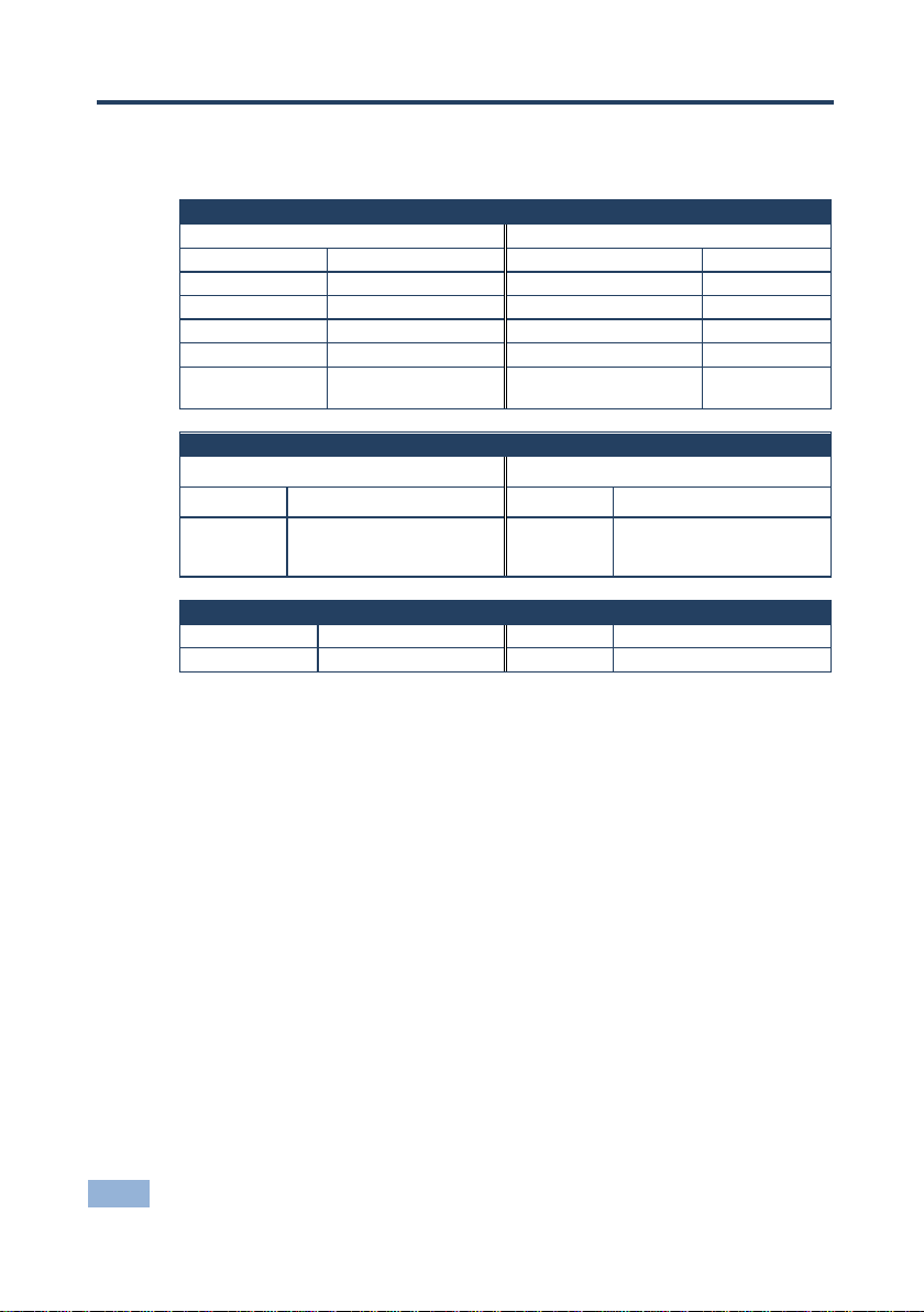
RS-232
Protocol 2000
Protocol 3000 (Default)
Baud Rate
9600
Baud Rate
9600
Data Bits
8
Data Bits
8
Stop Bits
1
Stop Bits
1
Parity
None
Parity
None
Command Format
HEX
Command Format
ASCII
1 to Input 1)
Input 1)
Switching Protocol
P2000 –> P3000
P3000 –> P2000
Command
0x38, 0x80, 0x83, 0x81
Command
#P2000<CR>
Front Panel
On the TO OUTPUT 1 row,
Front Panel
On the TO OUTPUT 1 row,
Ethernet
IP Address
192.168.1.39
TCP Port
5000
Subnet Mask
255.255.255.0
UDP Port
50000
9 Default Communication P ar a m eters
Example (Output
0x01, 0x81, 0x81 , 0x 81 Example (Output 1 to
press input butto ns 1 and 3
at
#VID1>1<CR>
press input buttons 1 and 2
at the same time
20 VS-42HDCP - Default Communication Parameters
Page 24

10 Default EDID
Monitor #2 [Real-time 0x0051]
Model name............... VS-42HDCP
Manufacturer....... .... .. KR M
Plug and Play ID......... KRM0200
Serial number............ 1
Manufacture date......... 2010, ISO week 24
Filter driver............ None
-------------------------
EDID revision............ 1.3
Input signal type........ Digital (DVI)
Color bit depth.......... Und e fined
Display type............. RGB color
Screen size.............. 700 x 390 mm (31.5 in)
Power management......... Not supported
Extension blocs....... ... 1 (CEA -EXT)
-------------------------
DDC/CI................... Not supported
Color characteristics
Default color space...... Non-sRGB
Display gamma.......... .. 2.2 0
Red chromaticity......... Rx 0.640 - Ry 0.341
Green chromaticity....... Gx 0.286 - Gy 0.610
Blue chromaticity........ Bx 0.146 - By 0.0 69
White point (default).... Wx 0.284 - Wy 0.293
Additional des cr i ptor s... None
Timing characteristics
Horizontal scan range.... 31-94kHz
Vertical scan range...... 50-85Hz
Video bandwidth.......... 170MHz
CVT standard............. Not supported
GTF standard............. Not supported
Additional des cr i ptor s... None
Preferred timing......... Yes
Native/pre ferr e d tim ing.. 1280x720 p at 60H z
Modeline............... "1280x720" 74.250 1280 1390 1430 1650 720 725 730 746 +hsync -vsync
Detailed timing #1....... 1920x1080p at 60Hz (16:9)
Modeline............... "1920x1080" 148.500 1920 2008 2052 2200 1080 1084 1089 1125 +hsync +vsync
Standard timings supported
720 x 400p at 70Hz - IBM VGA
720 x 400p at 88Hz - IBM XGA2
640 x 480p at 60Hz - IBM VGA
640 x 480p at 67Hz - Apple Mac II
640 x 480p at 72Hz - VESA
640 x 480p at 75Hz - VESA
800 x 600p at 56Hz - VESA
800 x 600p at 60Hz - VESA
800 x 600p at 72Hz - VESA
800 x 600p at 75Hz - VESA
832 x 624p at 75Hz - Apple Mac II
1024 x 768i at 87Hz - IBM
1024 x 768p at 60Hz - VESA
1024 x 768p at 70Hz - VESA
1024 x 768p at 75Hz - VESA
1280 x 1024p at 75Hz - VESA
1152 x 870p at 75Hz - Apple Mac II
1280 x 720p at 60Hz - VESA STD
1280 x 800p at 60Hz - VESA STD
1440 x 900p at 60Hz - VESA STD
1280 x 960p at 60Hz - VESA STD
1280 x 1024p at 60Hz - VESA STD
1400 x 1050p at 60Hz - VESA STD
1680 x 1050p at 60Hz - VESA STD
1600 x 1200p at 60Hz - VESA STD
EIA/CEA-861 Information
Revision number....... ... 3
IT underscan............. Not supported
Basic audio.............. Supported
YCbCr 4:4:4............ .. Su ppor te d
YCbCr 4:2:2............ .. Su ppor te d
VS-42HDCP - Default EDID 21
Page 25

Native formats......... .. 1
Detailed timing #1....... 720x480p at 60Hz (4:3)
Modeline... .. . ......... "720x4 80" 27.000 720 736 798 858 480 489 495 525 -hsync -vsync
Detailed timing #2....... 1920x1080i at 60Hz (16:9)
Modeline............... "1920x1080" 74.250 1920 2008 2052 2200 1080 1084 1094 1124 interlace +hsync +vsync
Detailed timing #3....... 1920x1080i at 50Hz (16:9)
Modeline............... "1920x1080" 74.250 1920 2448 2492 2640 1080 1084 1094 1124 interlace +hsync +vsync
Detailed timing #4....... 1280x720p at 60Hz (16:9)
Modeline............... "1280x720" 74.250 1280 1390 1430 1650 720 725 730 750 +hsync +vsync
Detailed timing #5....... 1280x720p at 50Hz (16:9)
Modeline............... "1280x720" 74.250 1280 1720 1760 1980 720 725 730 750 +hsync +vsync
CE video identifiers (VICs) - timing/formats supported
720 x 576p at 50Hz - EDTV (4: 3, 16:15)
1280 x 720p at 50Hz - HDT V ( 16: 9, 1:1)
1920 x 1080i at 60Hz - HDTV (16:9, 1:1)
1920 x 1080i at 50Hz - HDTV (16:9, 1:1)
1280 x 720p at 60Hz - HDTV (16:9, 1:1) [Native]
1920 x 1080p at 60Hz - HDTV (16:9, 1:1)
1920 x 1080p at 50Hz - HDTV (16:9, 1:1)
NB: NTSC refre sh rate = (Hz*1000)/1001
CE audio data (formats supported)
LPCM 3-channel, 24-bits at 44/48 kHz
CE speaker allocation data
Channel configuration.... 3.0
Front left/right......... Yes
Front LFE................ No
Front center............. Yes
Rear left/right.......... No
Rear center............. . No
Front left/right center.. No
Rear left/right center... No
Rear LFE............... .. No
CE vendor specific data (VSDB)
IEEE registration nu m ber. 0x000C03
CEC physical address..... 1.0 .0 .0
Maximum TMDS clock....... 165MHz
Report information
Date generated........... 26/12/2012
Software revisi o n........ 2.60.0.964
Data source.............. Real-time 0x0051
Operating system......... 5.1.2600.2.Service Pack 3
Raw data
00,FF,FF,FF,FF,FF,FF,00,2E,4D,00,02,01,00,00,00,18,14,01,03,81,46,27,78,0A,D5,7C,A3,57,49,9C,25,
11,48,4B,FF,FF,80,81,C0,81,00,95,00,81,40,81,80,90,40,B3,00,A9,40,01,1D,00,72,51,D0,1A,20,6E,28,
55,00,7E,88,42,00,00,1A,02,3A,80,18,71,38,2D,40,58,2C,45,00,C4,8E,21,00,00,1E,00,00,00,FC,00,56,
53,2D,34,32,48,44,43,50,0A,20,20,00,00,00,00,FD,00,32,55,1F,5E,11,00,0A,20,20,20,20,20,20,01,F2,
02,03,1A,71,47,11,13,05,14,84,10,1F,23,0A,06,04,83,05,00,00,65,03,0C,00,10,00,8C,0A,D0,8A,20,E0,
2D,10,10,3E,96,00,58,C2,21,00,00,18,01,1D,80,18,71,1C,16,20,58,2C,25,00,C4,8E,21,00,00,9E,01,1D,
80,D0,72,1C,16,20,10,2C,25,80,C4,8E,21,00,00,9E,01,1D,00,72,51,D0,1E,20,6E,28,55,00,C4,8E,21,00,
00,1E,01,1D,00,BC,52,D0,1E,20,B8,28,55,40,C4,8E,21,00,00,1E,00,00,00,00,00,00,00,00,00,00,00,90
22 VS-42HDCP - Default EDID
Page 26
MSB
LSB
DESTINATION
INSTRUCTION
7 6 5 4 3 2 1
0
1st byte
INPUT
1
I6
I5
I4
I3
I2
I1
I0 7 6 5 4 3 2 1 0
OUTPUT
1
O6
O5
O4
O3
O2
O1
O0
7 6 5 4 3 2 1
0
3rd byte
1
OVR X M4
M3
M2
M1
M0 7 6 5 4 3 2 1 0
4th byte
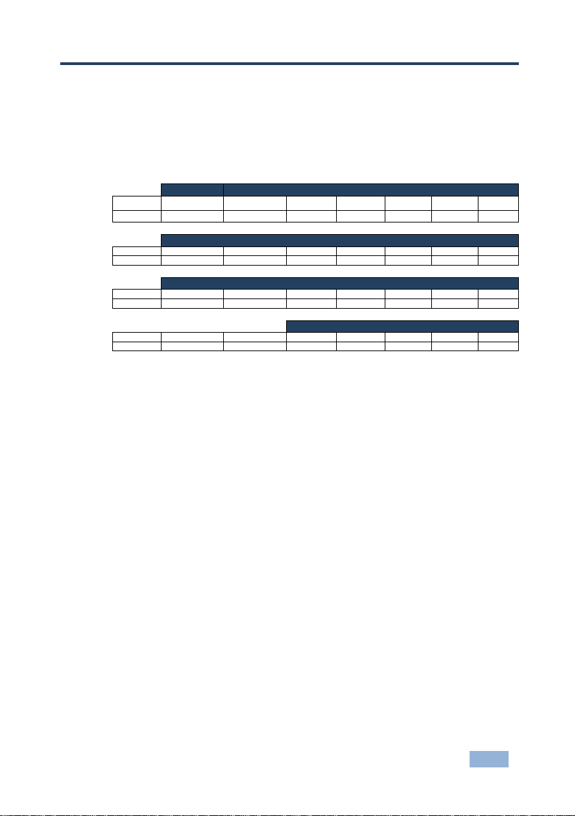
11 Kramer Protocol 2000
The Kramer Protocol 2000 RS-232/RS-485 communication uses four bytes of
information as defined below. All the values in the table are decimal, unless
otherwise stated.
0 D N5 N4 N3 N2 N1 N0
2nd byte
MACHINE NUMBER
1st BYTE: Bit 7 – Defined as 0.
D – “DESTINATION”: 0 - for sending information to the switchers (from the PC);
1 - for sending to the PC (from the switcher).
N5…N0 – “INSTRUCTION”
The function that is to be performed by the switcher(s) is defined by the INSTRUCTION (6 bits). Similarly, if a function is
performed via the machine’s keyboard, then these bits are set with the INSTRUCTION NO., which was performed. The
instruction codes are defined according to the table below (INSTRUCTION NO. is the value to be set for N5…N0).
2nd BYTE: Bit 7 – Defined as 1.
I6…I0 – “INPUT”.
When switching (ie. instruction codes 1 and 2), the INPUT (7 bits) is set as the input number which is to be switched.
Similarly, if switching is done via the machine’s front-panel, then these bits are set with the INPUT NUMBER which was
switched. For other o per a ti ons, these bits are de fi ne d acc or ding to the table.
3rd BYTE: Bit 7 – Defined as 1.
O6…O0 – “OUTPUT”.
When switching (ie. instruction codes 1 and 2), the OUTPUT (7 bits) is set as the output number which is to be
switched. Similarly, if switching is done via the machine’s front-panel, then these bits are set with the OUTPUT
NUMBER which was switched. For other operations, these bits are defined according to the table.
4th BYTE: Bit 7 – Defined as 1.
Bit 5 – Don’t care.
OVR – Machine number override.
M4…M0 – MACHINE NUMBER.
Used to address machines in a system via their machine numbers. When several machines are controlled from a single
serial port, they are usually configured together with each machine having an individual machine number. If the OVR bit
is set, then all machine numbers accept (implement) the command, and the addressed machine replies. For a single
machine controlled via the serial port, always set M4…M0 = 1, and make sure that the machine itself is configured as
MACHINE NUMBER = 1.
VS-42HDCP - Kramer Protocol 2000 23
Page 27
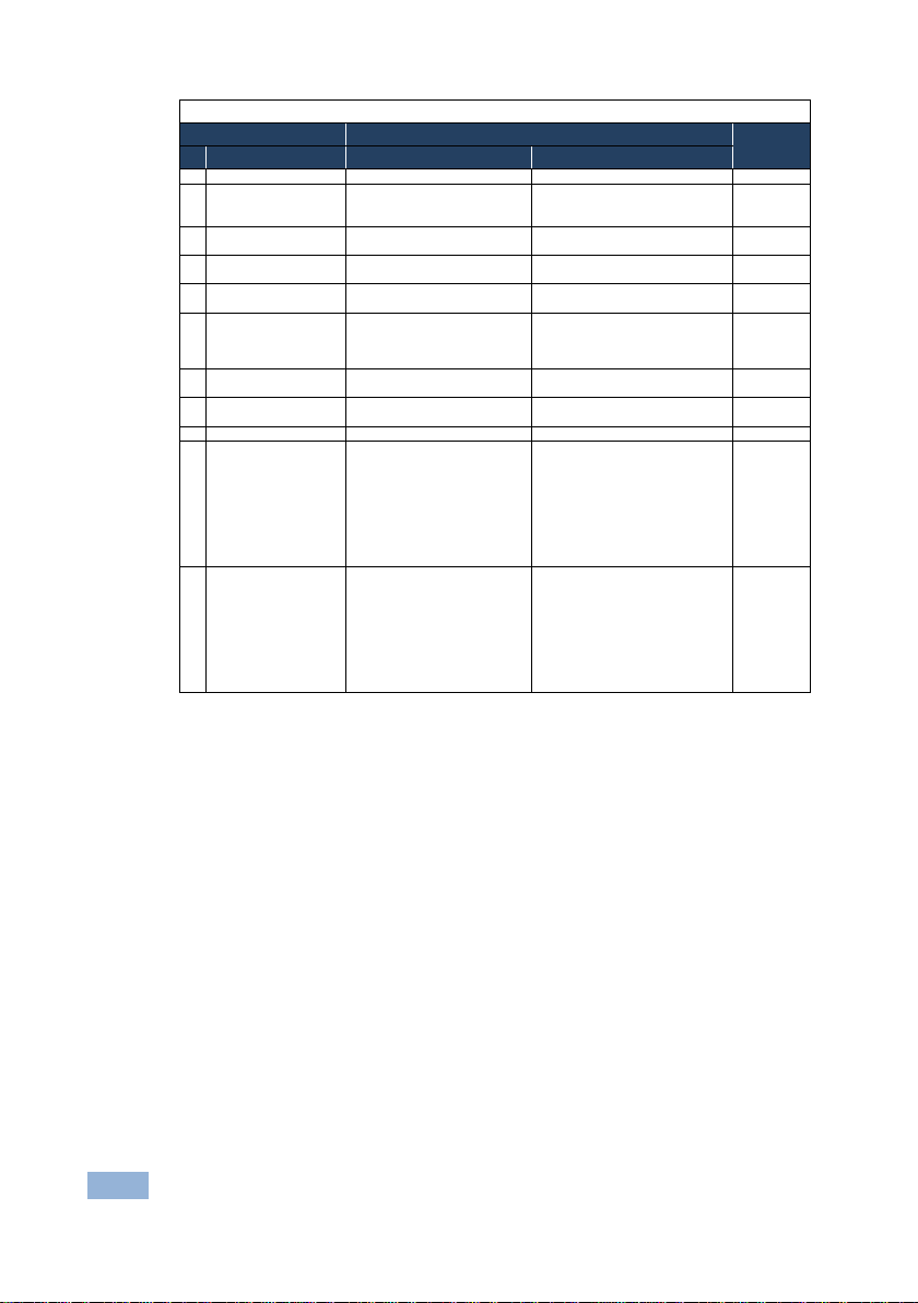
Instruction Codes for Protocol 2000
Instruction
Definition for Specific Instruction
Notes
#
Description
Input
Output
0
RESET VIDEO
0
0
1
1
SWITCH VIDEO
Set equal to video input which is
(0 = disconnect)
Set equal to video output which is
(0 = to all the outputs)
2, 15
3
STORE VIDEO
STATUS
Set as SETUP #
0 - to store
1 - to delete
2, 3, 15 4 RECALL VIDEO
STATUS
Set as SETUP #
0
2, 3, 15
5
REQUEST STATUS
OF A VIDEO OUTPUT
Set as SETUP #
Equal to output number whose
status is reqd
4, 3
15
REQUEST WHETHER
DETECTED
SETUP #
0 - for checking if setup is defined
8
30
LOCK FRONT PANEL
0 - Panel unlocked
1 - Panel locked
0
2
31
REQUEST WHETHER
PANEL IS LOCKED
0 0 16
56
CHANGE TO ASCII
0
Kramer protocol 30 00
19
61
IDENTIFY
1 - video machine name
9 - Protocol 2000 revision
0 - Request first 4 digits
13
62
62
DEFINE MACHINE
1 - number of inputs
1 - for video
controller
to be switched
SETUP IS DEFINED /
VALID INPUT IS
MACHINE
NOTES on the above tabl e:
NOTE 1 - When the master switcher is reset, (e.g. when it is turned on), the reset code is sent to the PC. If this code is
sent to the switchers, it resets according to the present power-down settings.
NOTE 2 - These a r e bi-directional definitions. That is, if the switcher receives the code, it performs the instruction; and if
the instruction is performed (due to a keystroke operation on the front panel), then these codes are sent. For example, if
the HEX code
01 85 88 83
was sent from the PC, then the switcher (machine 3) switches input 5 to output 8. If the user switched input 1 to output 7
via the front panel keypad, then the switcher sends HEX codes:
41 81 87 83
to the PC.
When the PC sends one of the commands in this group to the switcher, then, if the instruction is valid, the switcher
replies by sending to the PC the same four bytes that it was sent (except for the first byte, where the DESTINATION bit
is set high).
NOTE 3 - SETUP # 0 is the present setting. SETUP # 1 and higher are the settings saved in the switcher's memory, (i.e.
those used for Store a nd R ecal l ) .
NOTE 4 - The reply to a "REQUEST" instruction is as follows: the same instruction and INPUT codes as were sent are
returned, and the OUTPUT is assigned the value of the requested parameter. The replies to instructions 10 and 11 are
as per the definitions in instructions 7 and 8 respectively. For example, if the present status of machine number 5 is
breakaway setting, then the reply to the HEX code
0B 80 80 85
would be HEX codes
4B 80 81 85
NOTE 8 - The reply is as in TYPE 3 above, except that here the OUTPUT is assigned with the value 0 if the setup is not
defined / no valid input is detected; or 1 if it is defined / valid input is detected.
or
Input #
2 - audio machine name
3 - video software ver s i o n
4 - audio software version
5 - RS422 controller name
6 - RS422 controller version
7 - remote control nam e
8 - remote software version
to be switched
1 - for checking if input is valid
1 - Request first suffix
2 - Request second suffix
3 - Request third su ffix
10 - Request first pr e fix
11 - Request seco nd pr e fix
12 - Request third prefix
2 - number of outputs
3 - number of setups
2 - for audio
3 - for SDI
4 - for
remote
panel
5 - for RS422
24 VS-42HDCP - Kramer Protocol 2000
Page 28

NOTE 13 - This is a request to identify the switcher/s in the system. If the OUTPUT is set as 0, and the INPUT is set as
1, 2, 5 or 7, the machine sends its name. The reply is the decimal value of the INPUT and OUTPUT. For example, for a
2216, the reply to the request to send the audio machine name would be (HEX codes):
7D 96 90 81 (i.e. 128dec+ 22dec for 2nd byte, and 12 8d ec+ 16dec for 3rd byte) .
If the request for identification is sent with the INPUT set as 3 or 4, the appropriate machine sends its software version
number. Again, th e re ply wo ul d be the dec im al value of the INPUT and OU T PU T - the INPUT representing the number
in front of the decimal point, and the OUTPUT representing the number after it. For example, for version 3.5, the reply to
the request to send the version number would be (HEX codes):
7D 83 85 81 (i.e. 128dec+ 3dec f or 2n d byt e , 128 dec+ 5dec for 3rd byte).
If the OUTPUT is set as 1, then the ASCII coding of the lettering following the machine’s name is sent. For example, for
the VS-7588YC, the reply to the request to send the first suffix would be (HEX codes):
7D D9 C3 81 (i.e. 128dec+ ASCII for “Y”; 128dec+ ASCII for “C”).
NOTE 14 - The number of inputs and outputs refers to the specific machine which is being addressed, not to the
system. For example, if six 16X16 matrices are configured to make a 48X32 system (48 inputs, 32 outputs), the reply to
the HEX code
3E 82 81 82 (ie. request the number of outputs)
would be HEX codes
7E 82 90 82
ie. 16 outputs
NOTE 15 – When the OVR bit (4th byte) is set, then the “video” commands have universal meaning. For example,
instruction 1 (SWITCH VIDEO) causes all units (including audio, data, etc.) to switch. Similarly, if a machine is in
“FOLLOW” mode, it performs any “video” instruction.
NOTE 16 - The reply to the “REQUEST WHETHER PANEL IS LOCKED” is as in NOTE 4 above, except that here the
OUTPUT is assigned with the value 0 if the panel is unlocked, or 1 if it is locked.
NOTE 19 - After this instruction is sent, the unit will respond to the ASCII command set defined by the OUTPUT byte.
The ASCII command to operate with the HEX command set must be sent in order to return to working with HEX codes.
VS-42HDCP - Kramer Protocol 2000 25
Page 29

Start
Address (optional)
Body
Delimiter
#
@
Message
CR
Start
Body
Delimiter
Command SP Parameter_1,Parameter_2,…
CR
Start
Address
Body
Delimiter
#
device_id@
Command_1 Parameter1_1,Parameter1_2,…|
Command_3
i
12 Protocol 3000
By default, the VS-42HDCP is set to Protocol 3000 but is also compatible with
Kramer’s Protocol 2000 (see Section 11
Note that the VS-42HDCP needs to be set to Protocol 2000 in order to
use the IR remote control transmitter.
).
Section 9
The VS-42HDCP can be operated using serial commands from a PC, remote
controller or touch screen using the Kramer Protocol 3000. However, when used
in conjunction with the IR remote controller, these serial commands must also be
in Protocol 2000 format.
This section describes:
describes how to switch between Protocol 3000 and Protocol 2000.
• Kramer Protocol 3000 syntax (see Section 12.1
• Kramer Protocol 3000 commands (see Section 12.2)
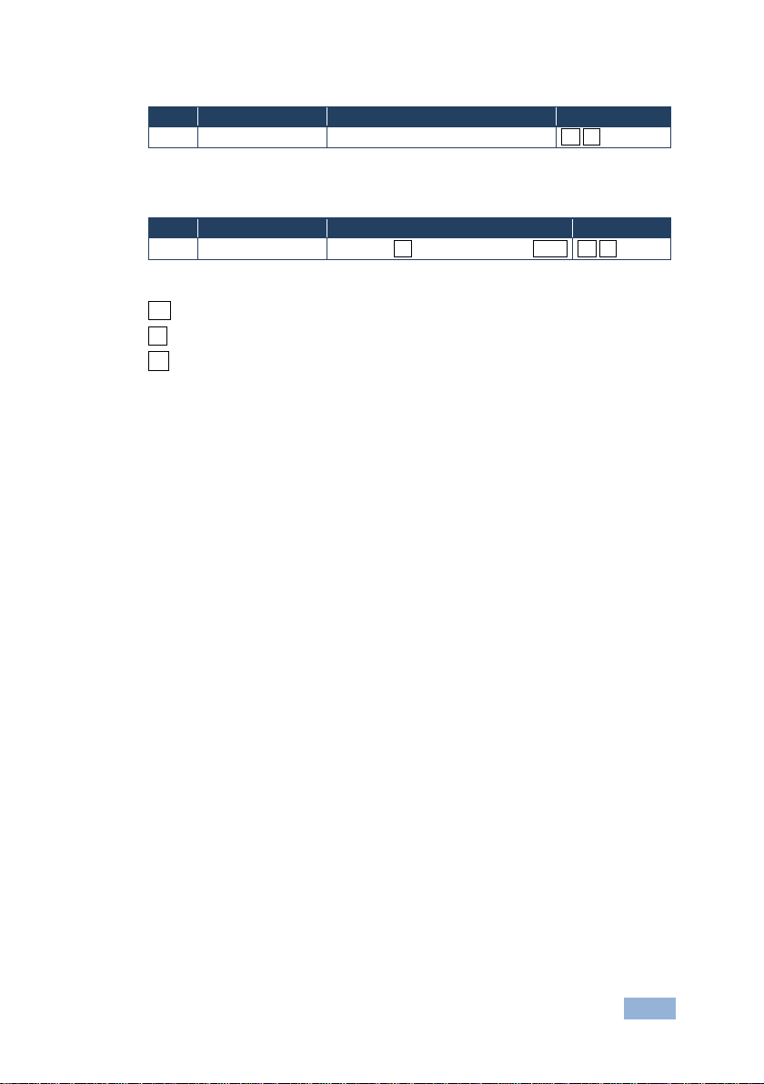
12.1 Kramer Protocol 3000 Syntax
12.1.1 Host Message Format
device_id
12.1.1.1 Simple Command
Command string with only one command without addressing:
#
12.1.1.2 Command String
)
Formal syntax with commands concatenation and addressing:
26 VS-42HDCP - Protocol 3000
Command_2 Parameter2_1,Parameter2_2,…|
Parameter3_1,Parameter3_2,…|…
CR
Page 30
Start
Address (optional)
Body
delimiter
~
@
Message
CR LF
Start
Address (optional)
Body
Delimiter
12.1.2 Device Message Format
device_id
12.1.2.1 Device Long Response
Echoing command:
~
device_id@
CR = Carriage return (ASCII 13 = 0x0D)
LF = Line feed (ASCII 10 = 0x0A)
SP = Space (ASCII 32 = 0x20)
12.1.3 Command Terms
Command
A sequence of ASCII letters ('A'-'Z', 'a'-'z' and '-').
Command and parameters must be separated by at least one space.
Parameters
A sequence of alphanumeric ASCII characters ('0'-'9','A'-'Z','a'-'z' and some special
characters for specific commands). Parameters are separated by commas.
Command SP [Param1 ,Param2 …] result CR LF
VS-42HDCP - Protocol 3000 27
Message string
Every command entered as part of a message string begins with a message
starting character and ends with a message closing character.
Note: A string can cont ai n more than one command. Commands are separated by
a pipe ( '|' ) character.
Message starting character
'#' – For host command/query
'~' – For device response
Device ID (Optional, for K-NET)
K-NET Device ID followed by '@'
Query sign
'?' follows some commands to define a query request.
Page 31

Message closing character
CR – For host messages; carri age return (ASCI I 13)
CRLF – For device m essages; carriage return (ASCII 13) + line-feed (ASCII 10)
Command chain separator character
When a message string contains more than one command, a pipe ( '|' ) character
separates each command.
Spaces between parameters or command terms are ignored.
12.1.4 Entering Commands
You can directly enter all commands using a terminal with ASCII communications
software, such as HyperTerminal, Hercules, etc. Connect the terminal to the serial
or Ethernet port on the Kramer device. To enter CR press the Enter key.
( LF is also sent but is ignored by command parser).
For commands sent from some non-Kramer controllers like Crestron, some
characters require special coding (such as, /X##). Refer to the controller manual.
12.1.5 Command Forms
Some commands have short name syntax in addition to long name syntax to allow
faster typing. The response is always in long syntax.
12.1.6 Chaining Commands
Multiple commands can be chained in the same string. Each command is
delimited by a pipe character (“|”). When chaining commands, enter the message
starting character and the message closing character only once, at the
beginning of the string and at the end.
Commands in the string do not execute until the closing character is entered.
A separate response is sent for every command in the chain.
12.1.7 Maximum String Length
64 characters
28 VS-42HDCP - Protocol 3000
Page 32

Command
Short
Form
Description
Permission
# Protocol handshak ing
End User
BUILD-
Read device build date
End User
DISPLAY?
Read if output is valid
End User
FACTORY
Reset to factory default configuration
GEDID
Read EDID data
User SW Internal
GEDID-EXT
Read EDID data from external device
connected to output
User SW Internal
HELP
List of commands
End User
IDV Visual identify device
End User
INFO-IO?
Read in/out count
End User
INFO-PRST?
Read maximum preset count
End User
LOCK-FP
LCK
Lock front panel
Administrator
LOCK-FP?
LCK?
Read Lock front panel
End User
MODEL?
Read device model
End User
P2000
Switch to protocol 2000
End User
PROT-VER?
Read device protocol version
End User
PRST-LST?
Read saved presets list
End User
PRST-RCL
Recall saved preset
End User
PRST-STO
Store current connections to preset
End User
preset
RESET
Reset device
Administrator
SIGNAL?
Read if input is valid
End User
SN? Read device serial number
End User
VERSION?
Read device firmware version
End User
VID Switch Video only
End User
VID? Get Video switch state
End User
i
12.2 Kramer Protocol 3000 Commands
DATE?
CPEDID Copy EDID data from the output to the
input EEPROM
End User
PRST-VID? Read video connections from saved
VS-42HDCP - Protocol 3000 29
End User
Note that the some of the following commands differ from the Kramer
standard protocol commands.
Page 33
-
BUILD-DATE?
BUILD-DATE␍
␍␊
Command - CPEDID
Get: - -
-
the input EEPROM
CPEDID␠
␍␊
output_id – Video output id
input_id – Video input id
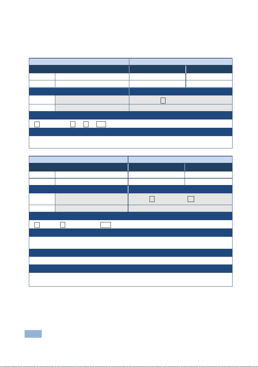
12.3 Kramer Protocol 3000 – Detailed Commands
This section describes the detailed commands list.
Command - BUILD-DATE
Command Name Permission Transparency
Set:
Get:
Description Syntax
Set: Get device build date
Get: - -
Response
~nn@BUILD-DATE␠date␠time
Parameters
date - Format: YYYY/MM/DD where YYYY = Year, MM = Month, DD = Day
time - Format: hh:mm:ss where hh = hours, mm = minutes, ss = seconds
Command Type - System-mandatory
- End User Public
#
Command Type - System
Command Name Permission Transparency
Set:
Description Syntax
Set:
Get: - -
Response
~nn@
Parameters
CPEDID
Copy EDID data from the output to
output_id, input_id
End User Public
#CPEDID␠
output_id, input_id
␍
Response Triggers
Response is sent to the com port from which the Set was received (before execution)
Notes
Destination bitmap size depends on device properties (for 64 inputs it is a 64-bit word)
Example: bitmap 0x0013 means inputs 1,2 and 5 are loaded with the new EDID
30 VS-42HDCP - Protocol 3000
Page 34
DISPLAY?
Set: - -
DISPLAY?␠
DISPLAY␠ out_id,status ␍␊
out_id - output numb er
valid
etc.) are stable and valid
Set:
FACTORY
End User
-
-
#FACTORY␍
Get : - -
FACTORY␠
␍␊
This command deletes all user data from the device. The deletion can take some time.
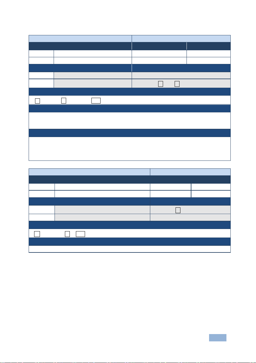
Command - DISPLAY?
Command Name Permission Transparency
Set: - - Get
Description Syntax
Command Type - System
End User Public
Get: Get output HPD status
Response
~ nn@
Parameters
status - HPD status according to signal val ida t ion – 0: Signal or sink is not valid, 1: Signal or sink is
Response Triggers
After execution, response is sent to the com port from which the Get was received
Response is sent after every change in output HPD status ON to OFF
Response is sent after every change in output HPD status OFF to ON and ALL parameters (new EDID,
#
out_id␍
Command – FACTORY Command Type – System-mandatory
Command Name Permission Transparency
Get:
Description Syntax
Set: Reset device to factory de fa ults configuration
Response
~nn@
Notes
OK
- -
VS-42HDCP - Protocol 3000 31
Page 35
GEDID
GEDID␠
␍␊
edid_data – EDID data as stream of bytes.
For Get, size=0 means EDID is not supported
For old devices that do not support this command, ~nn@ ERR 002␍␊ is received
Command – GEDID-EXT
Command Type - Common
GEDID-EXT
Read EDID from external device
␍␊
edid_data – EDID data as stream of bytes.
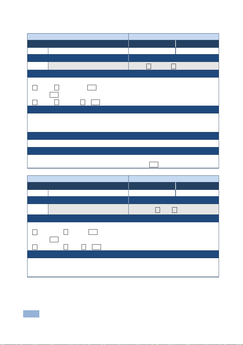
Command - GEDID
Command Name Permission Transparency
Get:
Description Syntax
Get: Read EDID data
Response
Multi line response:
~nn@GEDID␠ eeprom_id,size␍␊
EDID_data␍␊
~nn@GEDID␠ eeprom_id ␠OK
Parameters
eeprom_id – EEPROM to get the EDID from
– Device sends this parameter in response. Size of EDID that will print.
size
Response Triggers
Response is sent to the com port from whi ch the Set (b efo re e x ecution) / Get command was receive d
Notes
Command Type - System
End User Public
#
eeprom_id ␍
Command Name Permission Transparency
Get:
Description Syntax
Get:
Response
Multi line response:
~nn@GEDID-EXT␠ out_id,size␍␊
EDID_data␍␊
~nn@GEDID-EXT␠ out_id ␠OK
Parameters
out_id – EEPROM to get the EDID from
size
connected to output
– Device sends this param et er i n resp ons e. Size of EDID that will print.
End User Public
#GEDID-EXT␠ out_id ␍
32 VS-42HDCP - Protocol 3000
Page 36
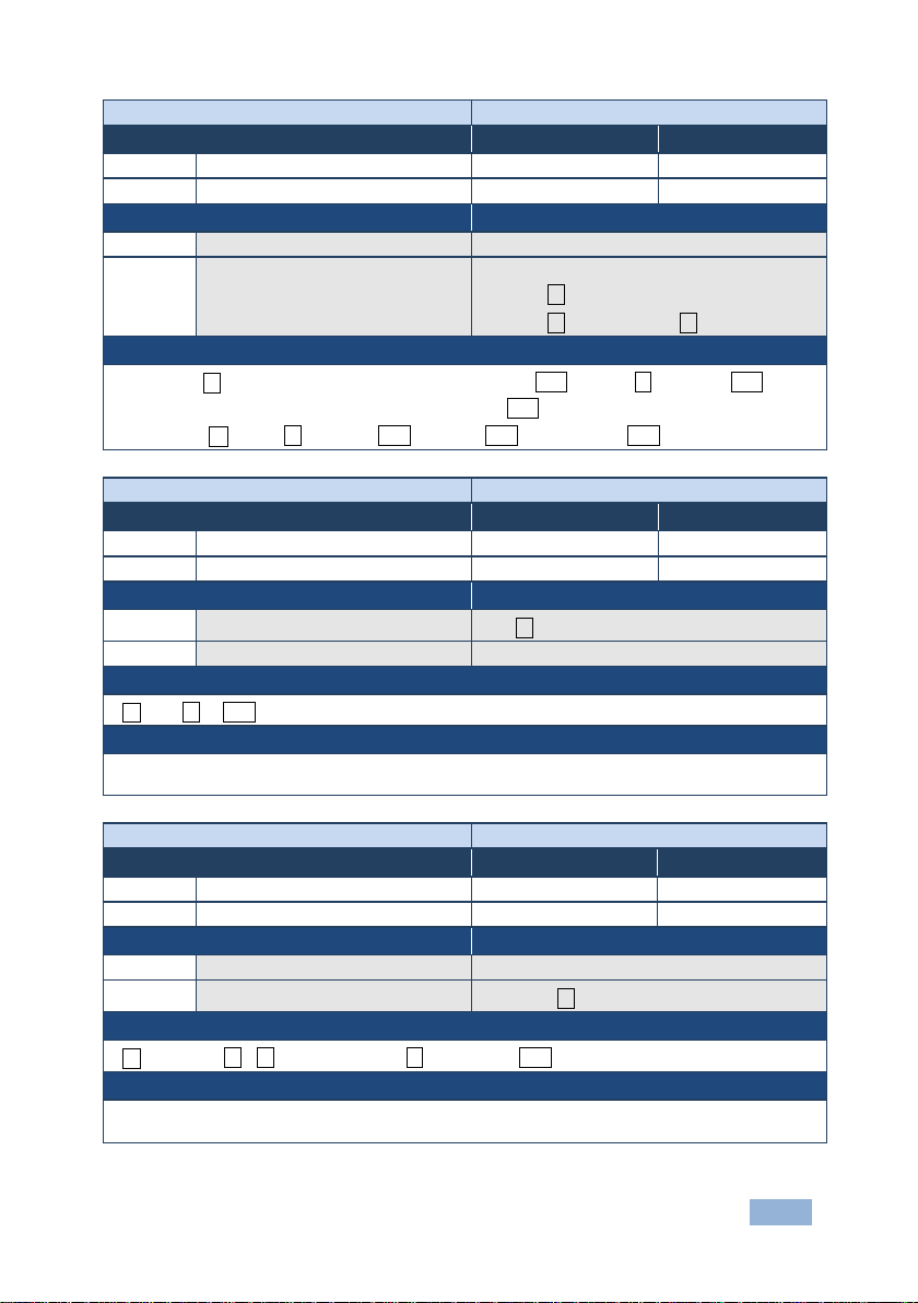
HELP
Set: - -
-
Set: - -
2 options:
Command - IDV
Command Type - System
IDV
IDV␍
␍␊
Command - INFO-IO?
Set: - -
-
INFO-IO?␠
inputs_count - number of inputs in the unit
Command -
Command Name Permission Transparency
Get:
Description Syntax
Get:
Response
1. Multi-line: ~nn@Device available p rotoco l 3000 co mmands :␍␊command,␠command…␍␊
To get help for command use: HELP (COMMAND_NAME)␍␊
2. Multi-line: ~nn@HELP␠ command:␍␊description␍␊ USAGE:usage ␍␊
HELP
Get command list or help for specific
command
Command Type - System-mandatory
End User Public
1. #HELP␍
2. #HELP␠command_name␍
Command Name Permission Transparency
Set:
Get:
Description Syntax
Set: Set visual indication from device
Get: - -
Response
~nn@IDV␠OK
Notes
Using this command, some devices can light a sequence of buttons or LEDs to allow identification of a
specific device from similar devices
-
End User Public
- -
#
Command Type - System
Command Name Permission Transparency
Get:
Description Syntax
Set: - Get: Get in/out count
Response
~nn@
Parameters
outputs_count - num b er of out puts in the unit
INFO-IO?
IN␠ inputs_count, OUT␠outputs_count␍␊
VS-42HDCP - Protocol 3000 33
End User Public
#INFO-IO?␍
Page 37
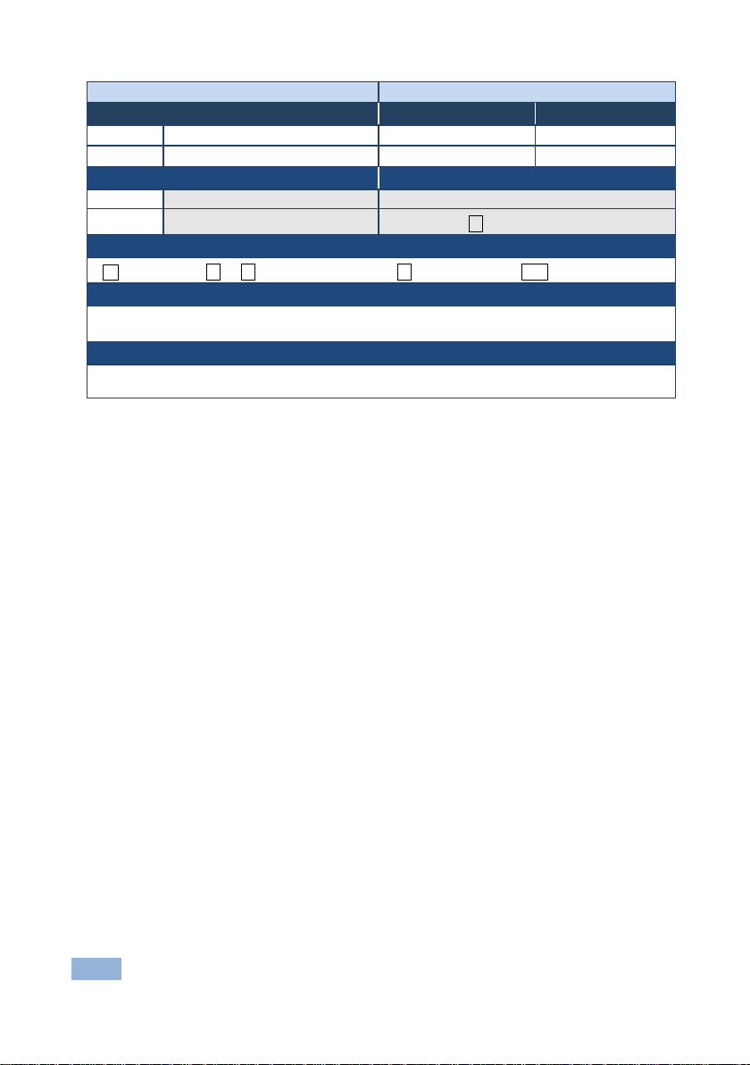
INFO-PRST?
Set: - -
-
Set: - -
INFO-PRST?␍
~nn@INFO-PRST?␠ VID␠ preset_video_count, AUD␠ preset_audio_count␍␊
preset_video_count - maximum number of video pre s ets in the unit
preset_audio_count - maximum number of audio presets in the unit
In most units, video and audio presets with the same number are stored and recalled together by
Command -
Command Name Permission Transparency
Get:
Description Syntax
Get: Get maximum preset count
Response
Parameters
Notes
commands #PRST-STO and #PRST-RCL
INFO-PRST?
Command Type - System
End User Public
#
34 VS-42HDCP - Protocol 3000
Page 38
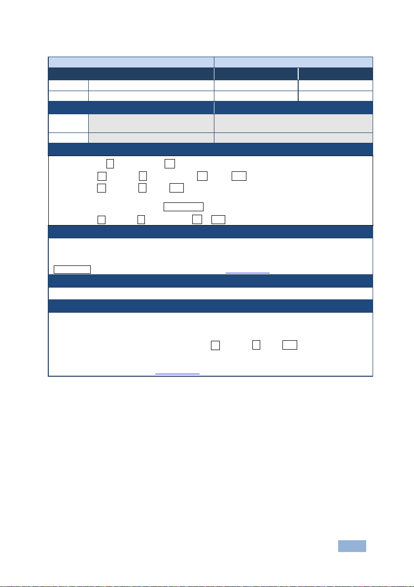
Command - LDEDID
Command Type - System
Set:
LDEDID
End User
Public
Get: - -
-
application to device
Get:
None
None
␠
␍␊
- HEX or KFW file in protocol packets (see Section 12.3.1)
When the unit receives the LDEDID command it replies with READY and enters the special EDID
Command Name Permission Transparency
Description Syntax
Set:
Communication Steps (Command and Response)
Step 1: #LDEDID␠ eeprom_id, size ␍
Response 1: ~nn@LDEDID␠ eeprom_id, size ␠ READY␍␊ or
~nn@LDEDID␠ERRnn␍␊
Step 2: If ready was received, send EDID_DATA
Response 2: ~nn@LDEDID
Parameters
eeprom_id – EEPROM to put the EDID into
size –Size of EDID that will send.
EDID_DATA
Response Triggers
Response is sent to the com port from which the Set (before execution)
Notes
Write EDID data from external
eeprom_id, size ␠OK
Multi-step syntax (see following steps)
packet wait mode. In this mode the unit can receive only packets and not regular protocol commands.
If the unit does not receive correct packets for 30 seconds or is interrupted for more than 30 seconds
before receiving all packets, it sends timeout error ~nn@LDEDID␠ ERR01␍␊ and returns to the
regular protocol mode. If the unit received data that is not a correct packet, it sends the corresponding
error and returns to the regular protocol mode.
See Protocol Packet reference in Section 12.3.1
VS-42HDCP - Protocol 3000 35
Page 39
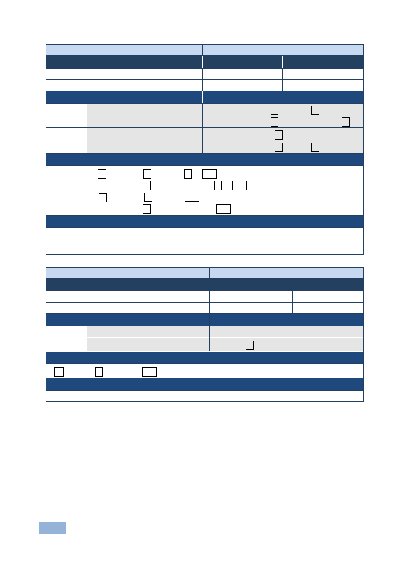
LOCK-FP
Set:
LOCK-FP
End User
Public
LOCK-FP␠
Option 2: #LOCK-FP?␠ device_id␍
LOCK-FP␠
Command – MODEL?
MODEL?
Get :
Get device model
MODEL␠
model_name – String of up to 19 printable ASCII chars
Command -
Command Name Permission Transparency
Get:
Description Syntax
Set: Lock front panel
Get: Get front panel lock state
Response
Set: Option 1: ~nn@LOCK-FP␠lock_mode␠ OK␍␊
Option 2: ~01@LOCK-FP␠device_id,lock_mode␠ OK␍␊
Get: Option 1: ~nn@LOCK-FP␠lock_mode␍␊
Option 2: ~01@
Parameters
lock_mode - 0/OFF - unlocks the front panel buttons, 1/ON - locks the front panel buttons
device_id - for K-Net controllers, select the button panel to lock. Locking is allowed only from the
master
LOCK-FP?
device_id, lock_mode␍␊
Command Type - System
End User Public
Option 1: #LOCK-FP␠ lock_mode␍
Option 2: #
Option 1: #LOCK-FP?␍
device_id,lock_mode␍
Command Type – System-mandatory
Command Name Permission Transparency
Set:
Get:
Description Syntax
Set: - -
Response
~nn@
Parameters
-
model_name␍␊
- End User -
#MODEL?␍
36 VS-42HDCP - Protocol 3000
Page 40
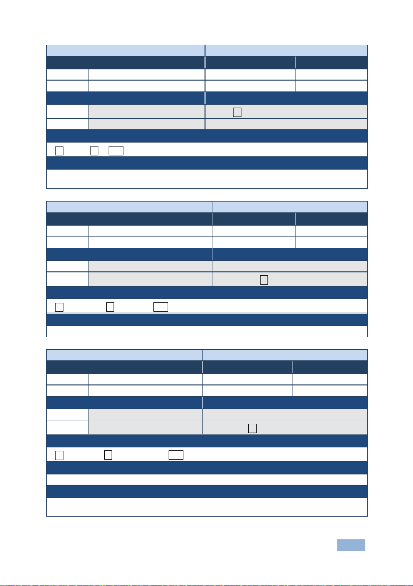
P2000
Set:
P2000
End User
Public
#P2000␍
P2000␠OK␍␊
Available only for devices that support Protocol 2000
-
PROT-VER?
Set: - -
PROT-VER?␍
PROT-VER␠
Version - XX.XX wher e X is a decim al digit
PRST-LST?
Set: - -
-
Set: - -
PRST-LST␠
preset - preset numb er
In most units, video and audio presets with the same number are stored and recalled together by
commands #PRST-STO and #PRST-RCL
Command -
Command Name Permission Transparency
Get:
Description Syntax
Set: Switch to protocol 2000
Get: - -
Response
~nn@
Notes
Protocol 2000 has a command to switch back to an ASCII protocol like Protocol 3000
-
Command Type - System
- -
Command - PROT-VER?
Command Name Permission Transparency
Set:
Get:
Description Syntax
Get: Get device protocol version
Response
~nn@
Parameters
3000:version␍␊
Command Type - System-mandatory
- End User Public
#
Command -
Command Name Permission Transparency
Get:
Description Syntax
Get: Get saved preset list
Response
~nn@
Parameters
Notes
PRST-LST?
VS-42HDCP - Protocol 3000 37
preset, preset, … ␍␊
Command Type - System
End User Public
#PRST-LST?␍
Page 41
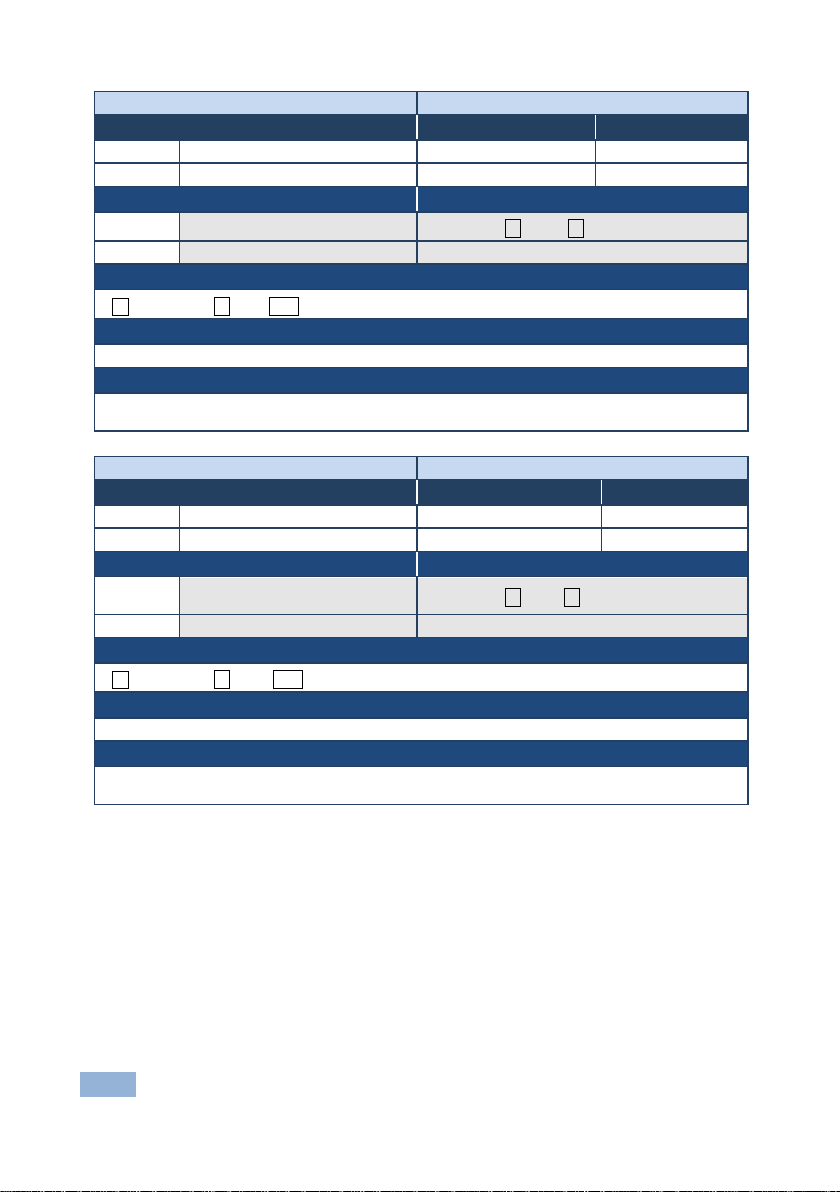
PRST-RCL
Set:
PRST-RCL
End User
Public
#PRST-RCL␠ preset ␍
PRST-RCL␠
In most units, video and audio presets with the same number are stored and recalled together by
commands #PRST-STO and #PRST-RCL
Command - PRST-STO
Command Type - System
Get: - -
-
Store current connections,
volumes and modes in preset
preset - preset numb er
In most units, video and audio presets with the same number are stored and recalled together by
commands #PRST-STO and #PRST-RCL
Command -
Command Name Permission Transparency
Get:
Description Syntax
Set: Recall saved preset list
Get: - -
Response
~nn@
Parameters
preset - preset numb er
Notes
-
preset␍␊
Command Type - System
- -
Command Name Permission Transparency
Set:
Description Syntax
Set:
Get: - -
Response
~nn@PRST-STO␠ preset␍␊
Parameters
PRST-STO
End User Public
#PRST-STO␠preset ␍
Notes
38 VS-42HDCP - Protocol 3000
Page 42
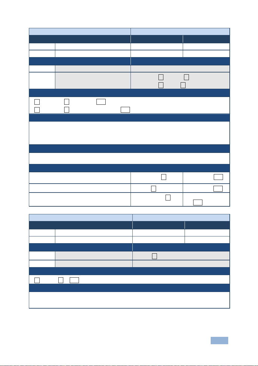
PRST-VID?
Set: - -
-
Set: - -
out - output number or '*' for all ou tpu ts
In most units, video and audio presets with the same number are stored and recalled together by
commands #PRST-STO and #PRST-RCL
Store current audio and video connections,
#PRCL 3␍
~PRST-RCL 3␍␊
Show source of video output 2 from preset 3
~PRST-VID 3,
RESET
-
#RESET␍
RESET␠ OK␍␊
To avoid locking the port due to a USB bug in Windows, disconnect USB connections immediately
port.
Command -
Command Name Permission Transparency
Get:
Description Syntax
Get:
Response
~nn@PRST-VID␠preset, in>out ␍␊
~nn@PRST-VID␠preset, in>1, in>2, in>3, … ␍␊
Parameters
preset - preset numb er
n - input number or '0' if output disconnected
> - connection character between in and out parameters
Notes
Examples
volumes and modes to preset 5
Recall audio and video conne c tio ns fro m preset 3
PRST-VID?
Get video connections from saved
preset
Command Type - System
End User Public
#PRST-VID?␠ preset, out␍
#PRST-VID?␠preset, * ␍
#PRST-STO 5␍ ~PRST-STO 5␍␊
#PRST-VID? 3,2␍
4>2␍␊
Command - RESET
Command Name Permission Transparency
Set:
Get:
Description Syntax
Set: Reset device
Get: - -
Response
~nn@
Notes
Command Type - System-mandatory
Administrator Public
- -
after running this command. If the port was locked, disconnect and reconnect the cable to reopen the
VS-42HDCP - Protocol 3000 39
Page 43
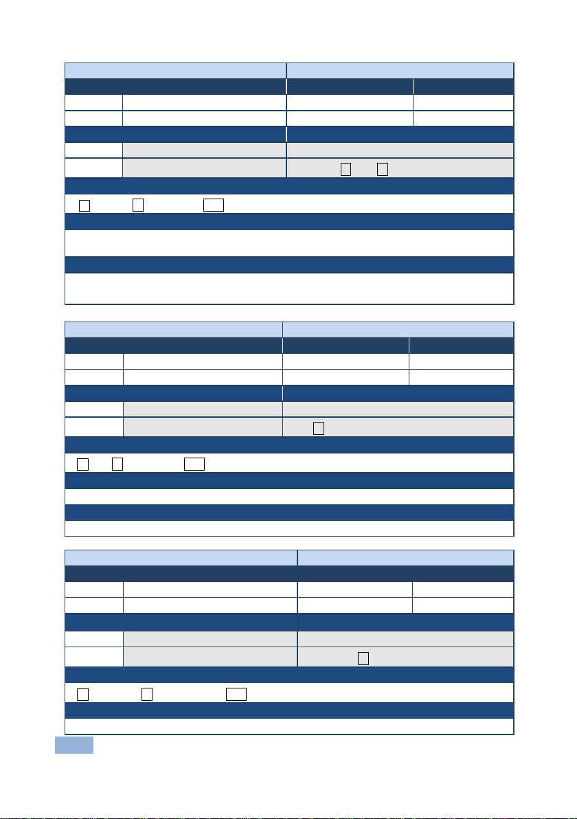
SIGNAL
Command Name
Permission
Transparency
Description
Syntax
#SIGNAL?␠inp_id␍
Response
~ nn@SIGNAL␠ inp_id,status ␍␊
Parameters
inp_id - input number
status - lock status according to signal validation – 0: Signal or sink is not valid, 1: Signal or sink is valid
Response Triggers
Command - SN?
Command Type - System-mandatory
-
Get:
SN?
End User
Public
Description
Syntax
Set: - -
Response
Parameters
Notes
Command –VERSION?
Command Type – System-mandatory
Set: - -
-
Description
Set: - -
Response
VERSION␠
Parameters
Command -
Set: - - Get
Set: - Get: Get input signal lock status
After execution, a response is sent to the com port from which the Get was received
Response is sent after every change in input signal status ON to OFF, or OFF to ON
SIGNAL?
Command Type - System
End User Public
Command Name Permission Transparency
Set:
Get: Get device serial number
~nn@SN␠serial_number␍␊
- -
#SN?␍
serial_number - 11 decimal digits, factory assigned
For new products with 14 digit serial numbers, use only the last 11 digits
Command Name Permission Transparency
Get:
Get : Get version number
~nn@
firmware_version – Format: XX.XX.XXX X wher e the digi t s gro up ar e: maj o r.minor.build version
40 VS-42HDCP - Protocol 3000
VERSION?
firmware_version␍␊
End User -
Syntax
#VERSION?␍
Page 44
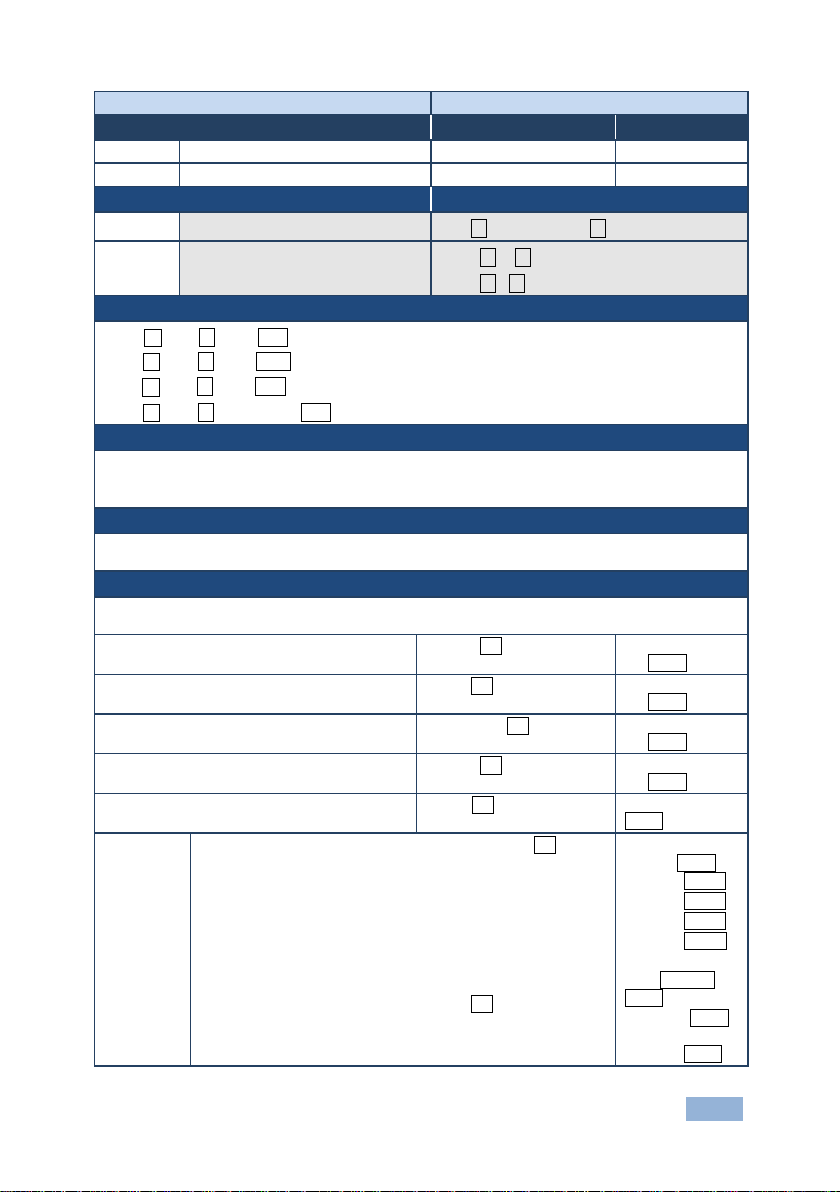
VID
Set:
VID
End User
Public
#VID␠ in>out, in>out,…␍
VID␠
␍␊
in - input number or '0' to disconnect output
command ~AV.
When AFV switching mode is active, this command also switches audio and the unit replies with
command ~AV.
Switch video and audio input 3 to output 7
~01@AV
Switch video input 2 to output 4
~01@VID
Switch video input 4 to output 2 in machine 6
~06@VID
Chaining
Command -
Command Type - Switch
Command Name Permission Transparency
Get:
VID?
End User Public
Description Syntax
Set: Set video switch state
Get: Get video switch state
#VID?␠ out␍
#VID?␠ * ␍
Response
Set: ~nn@VID␠in>out ␍␊
~nn@VID␠in>out ␍␊ …
Get: ~nn@VID␠in>out ␍␊
~nn@
in>1, in>2, …
Parameters
> - connection character between in and out parameters
out - output number or '*' for all ou tpu t s
Notes
When AFV switching mode is active, this command also switches audio and the unit replies with
Examples
#AV 3>7CR
3>7CRLF
#V 2>4CR
2>4CRLF
#6@VID 4>2CR
4>2CRLF
Disconnect video and audio output 4
Switch video input 3 to all outputs
multiple
commands
#AV 1>* | V 3>4, 2>2, 2>1, 0>2 | V 3>9 | A 0>1 | V? * CR
1. Switch audio and video from input 1 to all outputs
2. Switch video input 3 to output 4,
video input 2 to output 2,
video input 2 to output 1 and
disconnect video output 2
3. Switch video input 3 to output 9 (non-existent)
4. Disconnect audio output 1
5. Get status of all video links
Command processing begins after entering CR
A response is sent for each command after processing
#AV 0>4CR
#V 3>* CR
~01@AV
0>4CRLF
~01@VID 3>*
CRLF
~AV 1>*CRLF
~VID 3>4 CRLF
~VID 2>2 CRLF
~VID 2>1 CRLF
~VID 0>2 CRLF
~VID ERR003
CRLF
~AUD 0>1CRLF
~VID 2>1, 0>2,
1>3, 3>4 CRLF
VS-42HDCP - Protocol 3000 41
Page 45

Packet ID
Length
Data
CRC
12.3.1 Packet Protocol Structure
The packet protocol is designed to transfer large amounts of data, such as files, IR
commands, EDID data, and so on.
12.3.1.1 Using the Packet Protocol
To use the packet protocol:
1. Send a command: LDEDID
2. Receive Ready or ERR###
3. If Ready:
Send a packet
Receive OK on the last packet
Receive OK for the command
4. Packet structure:
Packet ID (1, 2, 3…) (2 bytes in length)
Length (data length + 2 for CRC) - (2 bytes in length)
Data (data length -2 bytes)
CRC - 2 bytes
01 02 03 04 05…
5. Response:
~NNNNSPOKCR LF
Where NNNN is the received packet ID in ASCII hex digits.
42 VS-42HDCP - Protocol 3000
Page 46

12.3.1.2 Calculating the CRC
The polynomial for the 16-bit CRC i s:
CRC-CCITT: 0x1021 = x
16
+ x12 + x5 + 1
Initial value: 0000
Final XOR Value: 0
For a code example, see:
http://sanity-free.org/133/crc_16_ccitt_in_csharp.html
CRC example:
Data = “123456789”
Result => 0x31C3
VS-42HDCP - Protocol 3000 43
Page 47
Page 48

For the latest information on our products and a list of Kramer distributors, visit
our Web site where
updates to this user manual may be found.
We welcome your questions, comments, and feedback.
Web site:
E
SAFETY WARNING
Disconnect the unit from the po wer
supply before opening and servicing
P/N:
2900-300218
Rev:
5
!
www.kramerav.com
-mail: [email protected]
 Loading...