

Page 1

USER MANUAL
MODEL:
VS-411UHD
UHD 4x1 Auto Switcher
P/N: 2900-300537 Rev 1
www.KramerAV.com
Page 2
Page 3
Page 4
Page 5
Page 6

Contents
1 Introduction 1
2 Getting Started 2
2.1 Achieving the Best Performance 2
2.2 Safety Instructions 2
2.3 Recycling Kramer Products 3
3 Overview 4
3.1 Defining the VS-411UHD UHD 4x1 Auto Switcher 5
4 Connecting the VS-411UHD 7
4.1 Connecting a Serial Controller to the VS-411UHD via RS-232 8
4.2 Setting the DIP-Switches 9
5 Operating the VS-411UHD 10
5.1 Switching – Manual and Auto 10
5.2 Setting the Switching Speed 11
5.3 Muting the Output 12
5.4 Copying the EDID 12
5.5 Setting the 5V Output Time Delay 12
5.6 Setting HDCP Capability 12
5.7 Setting Audio Output 13
5.8 Using the Remote Control 14
5.9 Step-In Support 14
5.10 Using VCOM on USB 14
5.11 Upgrading the Firmware 14
6 Controlling the VS-411UHD 15
6.1 Using the Front Panel Buttons 15
6.2 Switching via the Terminal Block Connector 16
6.3 Using the RC-IR3 Remote Control Transmitter with the VS-411UHD 17
6.4 Connecting to the VS-411UHD via RS-232 17
6.5 Performing a Factory Reset 18
7 Technical Specifications 19
8 Supported Resolutions 20
9 Default Settings 21
9.1 Default Communication Settings 21
9.2 First Power On Default Settings 21
9.3 Default EDID 22
10 Protocol 3000 24
10.1 Understanding Protocol 3000 25
10.2 Kramer Protocol 3000 Syntax 27
10.3 Protocol 3000 Commands 28
Figures
Figure 1: VS-411UHD 4x1 Auto Switcher 5
Figure 2: Connecting the VS-411UHD UHD 4x1 Auto Switcher 8
Figure 3: AUDIO SELECT DIP-Switches 9
Figure 4: Connecting the Contact Closure Remote Control Pins 16
Figure 5: RS-232 Pinout 17
VS-411UHD – Contents i
Page 7

1 Introduction
Welcome to Kramer Electronics! Since 1981, Kramer Electronics has been
providing a world of unique, creative, and affordable solutions to the vast range of
problems that confront video, audio, presentation, and broadcasting professionals
on a daily basis. In recent years, we have redesigned and upgraded most of our
line, making the best even better!
Our 1,000-plus different models now appear INPUT 14 groups that are clearly
defined by function: GROUP 1: Distribution Amplifiers; GROUP 2: Switchers and
Routers; GROUP 3: Control Systems; GROUP 4: Format/Standards Converters;
GROUP 5: Range Extenders and Repeaters; GROUP 6: Specialty AV Products;
GROUP 7: Scan Converters and Scalers; GROUP 8: Cables and Connectors;
GROUP 9: Room Connectivity; GROUP 10: Accessories and Rack Adapters;
GROUP 11: Sierra Video Products; GROUP 12: Digital Signage; GROUP 13:
Audio; and GROUP 14: Collaboration.
Congratulations on purchasing your Kramer VS-411UHD UHD 4x1 Auto Switcher,
which is ideal for the following typical applications:
• Mid- to small-sized meeting/conference rooms
• Educational lecture rooms
• Systems that require automatic HDMI routing
• Presentation and multimedia applications
VS-411UHD - Introduction
1
Page 8
available (where appropriate).
Caution:
There are no operator serviceable parts inside the unit
provided with the unit
before installing
2 Getting Started
We recommend that you:
• Unpack the equipment carefully and save the original box and packaging
materials for possible future shipment
• Review the contents of this user manual
Go to www.kramerav.com/downloads/VS-411UHD to check for up-to-date
user manuals, application programs, and to check if firmware upgrades are
2.1 Achieving the Best Performance
To achieve the best performance:
• For optimum range and performance, use the recommended Kramer cables
available at www.kramerav.com/product/VS-411UHD
• Do not secure the cables in tight bundles or roll the slack into tight coils
• Avoid interference from neighbouring electrical appliances that may
adversely influence signal quality
• Position your Kramer VS-411UHD away from moisture, excessive sunlight
and dust
This equipment is to be used only inside a building. It may only be
connected to other equipment that is installed inside a building.
2.2 Safety Instructions
Warning:
Warning:
2 VS-411UHD - Getting Started
Use only the Kramer Electronics power supply that is
Disconnect the power and unplug the unit from the wall
Page 9

2.3 Recycling Kramer Products
The Waste Electrical and Electronic Equipment (WEEE) Directive 2002/96/EC aims
to reduce the amount of WEEE sent for disposal to landfill or incineration by
requiring it to be collected and recycled. To comply with the WEEE Directive,
Kramer Electronics has made arrangements with the European Advanced
Recycling Network (EARN) and will cover any costs of treatment, recycling and
recovery of waste Kramer Electronics branded equipment on arrival at the EARN
facility. For details of Kramer’s recycling arrangements in your particular country go
to our recycling pages at www.kramerav.com/support/recycling/.
VS-411UHD - Getting Started
3
Page 10

3 Overview
The VS-411UHD is an automatic switcher for HDMI (up to 4K@60Hz (4:2:0)) and
analog audio signals. The unit automatically switches one of four HDMI inputs to a
predefined or the last connected input whenever the currently active video signal is
interrupted or whenever a higher-priority video signal is detected. It also supports
Kramer’s Step-in over HDMI technology.
The unit can embed analog audio to an HDMI signal and can extract the audio from
either an input HDMI signal or an output Audio Return Channel (ARC) HDMI signal.
The VS-411UHD can output an analog audio source on the HDMI output even
when an HDMI source is not connected and enters sleep mode when no input is
detected.
The VS-411UHD features:
• Maximum data rate 8.91Gbps (2.97Gbps per graphic channel)
• Resolution support for up to 4K@60Hz (4:2:0) UHD
• Supports Kramer Step-In over HDMI technology
• HDTV compatible
• Active switching – selectable manual or fast auto switching according to last
connected or preset priority
• HDMI 1.4, HDCP and DVI 1.0 compliant
• HDMI 1.4 support for Deep Color, 3D, ARC, up to 7.1 uncompressed audio
channels
• HDMI 1 input supports CEC and ARC
• HDMI ARC de-embedding from output to balanced stereo audio line out,
uncompressed
• Automatic video input detection and selection
• Auto-power off when no HDMI input for 10 seconds (selectable)
• HDCP on/off switching
• EDID configuration options
4 VS-411UHD - Overview
Page 11
• Default EDID
• Contact closure for remote manual switching override
• Audio embedding/de-embedding
• Analog audio input per port
• A LOCK button to prevent tampering
• Firmware upgrade over RS-232, mini-USB
• Support for Protocol 3000, EDID Designer, K-Upload via RS-232
• Varied control options – front panel buttons, contact closure, IR, RS-232
Protocol 3000
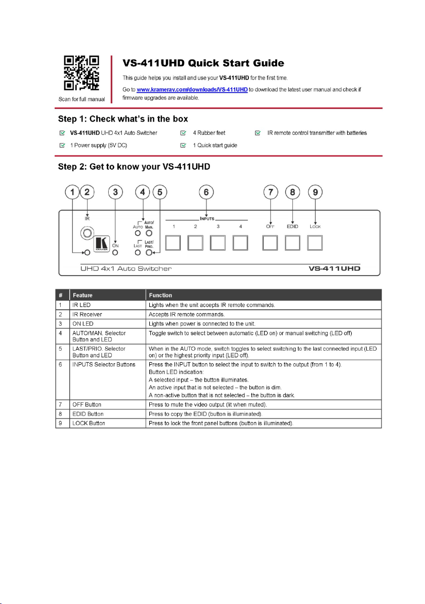
3.1 Defining the VS-411UHD UHD 4x1 Auto Switcher
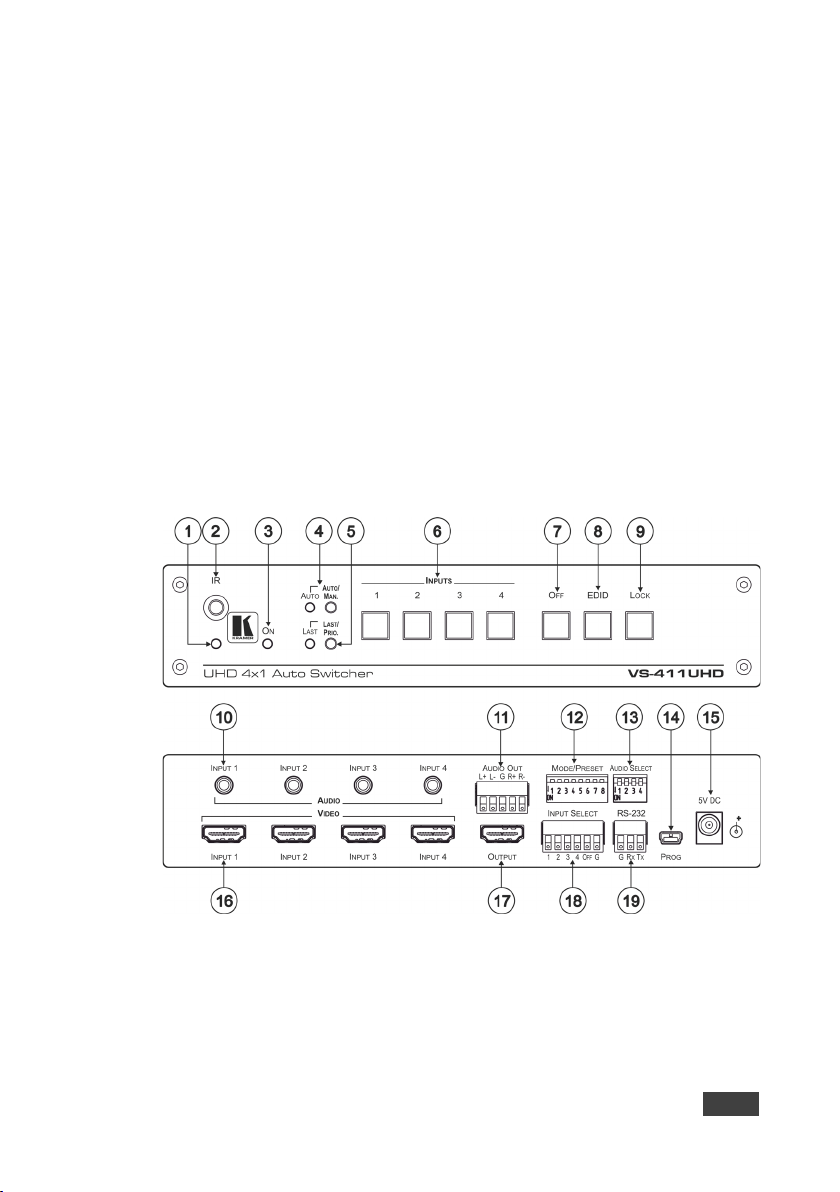
This section defines the VS-411UHD.
Figure 1: VS-411UHD 4x1 Auto Switcher
VS-411UHD - Overview
5
Page 12
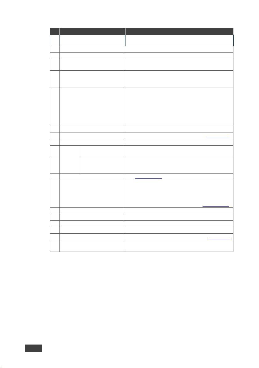
#
Feature
Function
1
IR LED
Lights yellow when the unit accepts IR remote
2
IR Receiver
Accepts IR remote commands.
3
ON LED
Lights when power is connected to the unit.
LED
manual switching (LED off).
5
LAST/PRIO. Selector Button
When in the AUTO mode, toggle switch to select
highest priority input (LED off).
6
INPUT Select Buttons
Press the INPUT button to select the input to switch to
dark. 7 OFF Button
Press to mute the video output (lit when muted).
8
EDID Button
Press to copy the EDID (button is lit), see Section 5.4.
9
LOCK Button
Press to lock the front panel buttons (button is lit).
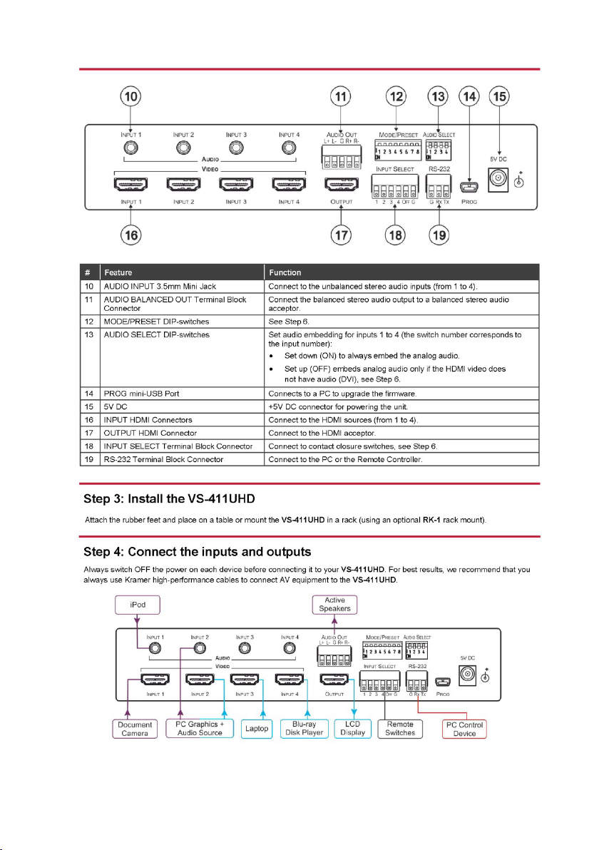
10
AUDIO
INPUT 3.5mm Mini
Jack
Connect to the unbalanced stereo audio inputs (from 1
to 4).
11
BALANCED OUT
Connect the balanced stereo audio output to a
12
MODE/PRESET DIP-switches
See Section 4.2.1.
13
AUDIO SELECT DIP-switches
Set audio embedding for inputs 1 to 4 (the switch
video does not have audio (DVI), see Section 4.2.2.
14
PROG mini-USB Port
Connects to a PC to upgrade the firm ware.
15
5V DC
+5V DC connector for powering the unit.
16
INPUT HDMI Connectors
Connect to the HDMI sources (from 1 to 4).
17
OUTPUT HDMI Connector
Connect to the HDMI acceptor.
18
INPUT SELECT Terminal Block
Connects to contact closure switches, see Section 6.2.
Connector
commands.
4 AUTO/MAN Selector Button and
and LED
Terminal Block
Connector
Toggle switch to select between automatic (LED on) or
switching to the last connected input (LED on) or the
the output (from 1 to 4).
Button LED indication:
A selected input – the button illuminates.
An active input that is not selected – the button is dim.
A non-active input that is not selected – the button is
balanced stereo audio acceptor.
number corresponds to the input number):
• Set down (ON) to always embed the analog audio.
• Set up (OFF) embeds analog audio only if the HDMI
19 RS-232 Terminal Block
6 VS-411UHD - Overview
Connect to the PC or the Remote Controller.
Page 13

power and then switch on the power to each device.
4 Connecting the VS-411UHD
Always switch off the power to each device before connecting it to
your VS-411UHD. After connecting your VS-411UHD, connect its
You do not have to connect all the inputs and outputs, connect only
those that are required.
To connect the VS-411UHD as illustrated in the example in Figure 2
1. Connect an HDMI source (for example, a laptop) to the INPUT 1 HDMI
connector and connect an analog audio source (for example, an audio
player) to the INPUT 1 3.5 mini-jack connector.
You can also connect a DVD player with a DVI connector, using a DVI-HDMI adapter to
transfer video signals
2. Connect HDMI sources (examples: document camera, Blu-ray player, or PC)
to the INPUT 2, 3, 4 HDMI connectors and connect audio inputs as required
to the INPUT 2, 3, 4 3.5 mini-jack connectors.
3. Connect the OUT HDMI connector to the HDMI acceptor (for example, an
LCD display).
4. Connect the AUDIO OUT terminal block connector to a balanced stereo
audio acceptor (for example, active speakers).
5. Set the AUDIO SELECT DIP-switches (see Section 5.1.2
6. Set the MODE/PRESET DIP-switches (see Section 5.1.2)
7. If required, connect a PC and/or controller to the RS-232 terminal block
connector (see Section 4.1
).
:
)
8. If required, connect the contact closure terminal block connectors (see
Section 6.2
9. Connect the 5V DC power adapter to the power socket and connect the
adapter to the mains electricity (not shown in Figure 2
VS-411UHD - Connecting the VS-411UHD
).
).
7
Page 14
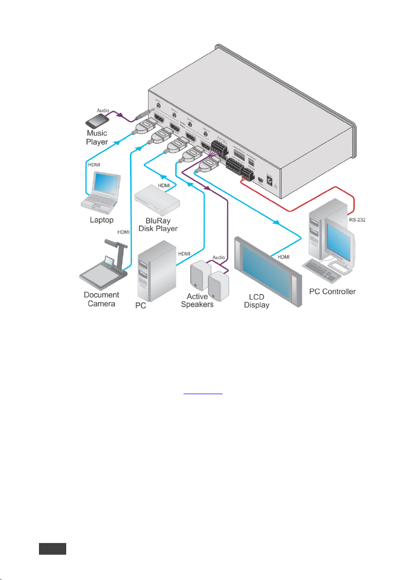
Figure 2: Connecting the VS-411UHD UHD 4x1 Auto Switcher
4.1 Connecting a Serial Controller to the VS-411UHD via RS-232
The VS-411UHD operates at two baud rates – 9600 (default) and 115,200 (see all
communication parameters in Section 9.1
).
To connect a serial controller to the VS-411UHD:
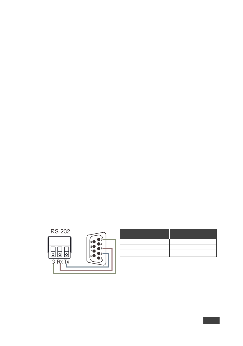
• From the RS-232 9-pin D-sub serial port on the serial controller connect:
• Pin 2 to the TX pin on the VS-411UHD RS-232 terminal block
• Pin 3 to the RX pin on the VS-411UHD RS-232 terminal block
• Pin 5 to the GND pin on the VS-411UHD RS-232 terminal block
8 VS-411UHD - Connecting the VS-411UHD
Page 15
DIP
Function
Off (Up)
On (Down)
1
Audio EDID
Pass audio EDID of sink.
Limit to 2-CH LPCM (effective only
after DIP 3 is set to on (down)).
sink.
after DIP 3 is set to on (down)).
3
Lock EDID
Pass EDID of sink.
Lock current display EDID and the
1st HDMI input
From
7
Output Off
Disable (to support audio only
Enable
8
Output Off Delay
Settings
15sec default (configurable).
15min
DIP #
Function
Description
1
Input 1 audio embedding
Embed analog audio only
Always embed analog
2
Input 2 audio embedding
3
Input 3 audio embedding
4
Input 4 audio embedding
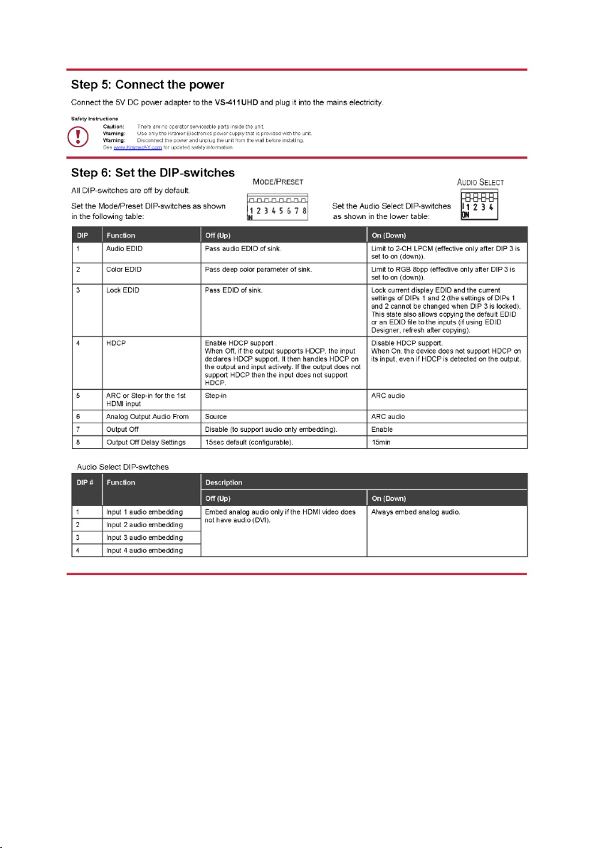
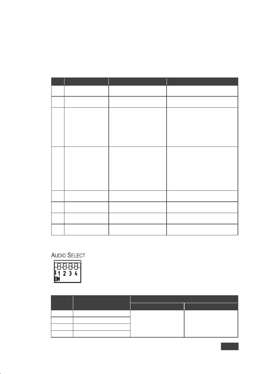
4.2 Setting the DIP-Switches
The DIP-switches dictate the behavior of the VS-411UHD. All DIP-switches are off
by default.
4.2.1 Mode/Preset DIP-Switches
2 Color EDID Pass deep color parameter of
4 HDCP Enable HDCP support.
5 ARC or Step-in for the
6 Analog Output Audio
When Off, if the output
supports HDCP, the input
declares HDCP support. It
then handles HDCP on the
output and input actively. If
the output does not support
HDCP then the input does not
support HDCP.
Step-in ARC audio
Source ARC audio
embedding).
4.2.2 Audio Select DIP-Switches
Limit to RGB 8bpp (effective only
current settings of DIPs 1 and 2 (the
settings of DIPs 1 and 2 cannot be
changed when DIP 3 is locked).
This state also allows copying the
default EDID or an EDID file to the
inputs (if using EDID Designer,
refresh after copying).
Disable HDCP support.
When On, the device does not
support HDCP on its input, even if
HDCP is detected on the output.
Figure 3: AUDIO SELECT DIP-Switches
VS-411UHD - Connecting the VS-411UHD
Off (Up) On (Down)
if the HDMI video does
audio.
not have audio.
9
Page 16

5 Operating the VS-411UHD
This section describes the VS-411UHD setup.
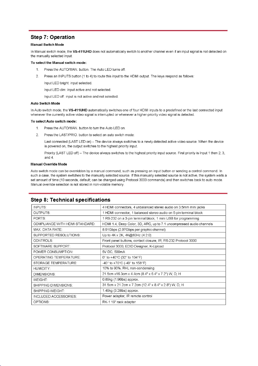
5.1 Switching – Manual and Auto
Switching can be performed automatically or manually using the device’s keypad,
remote control, or control commands. This section describes using the keypad
buttons to select Auto or Manual switch modes. The same procedure can also be
used for controlling switching via the remote control. For information about
switching via control commands, see Section 10.3
5.1.1 The Manual Switching Mode
In the manual mode, the VS-411UHD acts as a regular switcher, switching the input
video and audio signals to the output via the four front panel INPUT buttons.
To select the Manual switch mode:
1. Press the AUTO/MANUAL button to turn the AUTO LED off.
.
2. Press the INPUT1 to INPUT4 button to route this input to the HDMI output.
The keys respond as follows:
• Input LED bright: input active and selected
• Input LED dim: input active and not selected
• Input LED off: input is not active and not selected
5.1.2 Auto Switch Mode
In Auto switch mode, the VS-411UHD automatically switches one of four HDMI
inputs to a predefined or the last connected input whenever the currently active
video signal is interrupted or whenever a higher-priority video signal is detected.
10 VS-411UHD - Operating the VS-411UHD
Page 17

To select Auto switch mode:
1. Press the AUTO/MAN. button to turn the AUTO LED on.
2. Press the LAST/PRIO. button to select an auto switch mode:
• Last connected (LAST LED on) – The device always switches to a
newly detected active video source. When the device is powered on,
the output switches to the highest priority input
• Priority (LAST LED off) – The device always switches to the highest
priority input source. The default priority is Input 1 then Input 2.
5.1.3 Manual Override Mode
Auto switch mode can be overridden by a manual command, such as pressing an
input button or sending a control command. In such a case, the system switches to
the manually selected source. If this manually selected source is not active, the
system waits a set amount of time (10 seconds, default) and then switches back to
auto mode. Manual override selection is not stored in non-volatile memory.
5.2 Setting the Switching Speed
The VS-411UHD supports setting normal and fast (default) switching speeds.
To set switching speed modes:
1. Disconnect device power.
2. Press and hold one of the following buttons together with the OFF button:
• INPUT 1 button – for setting fast switching speed mode.
• INPUT 2 button – for setting normal switching speed mode.
3. Power the device on.
The device switching speed is modified.
VS-411UHD - Operating the VS-411UHD
11
Page 18

5.3 Muting the Output
• Press the OFF button to mute the audio and video outputs
5.4 Copying the EDID
The EDID is a data structure transmitted by the display that enables the
VS-411UHD to recognize the display connected to the output. The VS-411UHD
acquires and stores the EDID to make reconnection to the display effortless.
When the device is first powered on, it has default EDID loaded. The device
automatically reads and saves the first read EDID. Use DIP-switches 1-3 to set
EDID functionality (see Section 4.2
While copying EDID data, the input port’s HPD function changes from Low to High
which may affect the channel’s auto-switching.
The device automatically recognizes EDID differences between
input and output channels based on parts of the EDID data,
including manufacturer, serial number, and first block check-sum
information. EDID data is not copied if any difference is recognized.
Note: If a corrupted EDID is copied, the device loads the default
EDID on all inputs.
).
5.5 Setting the 5V Output Time Delay
Use DIP-switch 8 to set the delay time. Off (Up) delays 15 seconds, On (Down)
delays 15 minutes. A Protocol 3000 command can modify the delay time.
When there is no signal clock or 5V input on all inputs for the set delay, the device
shuts down the 5V output.
5.6 Setting HDCP Capability
The VS-411UHD supports HDCP communication automatically, by default. When
HDCP is detected in the input signal, it is enabled in the output signal. You can also
disable HDCP support using DIP-switch 4 (see Section 4.2
HDCP support is universal for all inputs.
12 VS-411UHD - Operating the VS-411UHD
). Enabling or disabling
Page 19

HDMI signal.
audio channels.
5.7 Setting Audio Output
The VS-411UHD enables customizing the audio output by embedding audio in
HDMI, de-embedding HDMI ARC from output to the uncompressed balanced stereo
audio line out, or routing the HDMI / analog inputs to the uncompressed balanced
stereo audio line out.
5.7.1 Embedding Audio in HDMI
The VS-411UHD can output audio to the HDMI Out port from the original HDMI
input or the Analog unbalanced 3.5mm audio input, by embedding it in the HDMI
input signal. The VS-411UHD enables setting the audio output separately for each
input using DIP-switches 5 and 6 (see Section 4.2
An Input 1 analog audio signal can only be embedded in the Input 1
HDMI signal.
An Input 2 analog audio signal can only be embedded in the Input 2
5.7.2 Outputting Audio from ARC or Device Inputs
The VS-411UHD can output audio to the balanced stereo Audio Out terminal block
from the following input sources:
).
VS-411UHD - Operating the VS-411UHD
• ARC – In this mode, the device does not enable embedding audio in the
HDMI signal.
• HDMI inputs / Analog unbalanced 3.5mm audio inputs – In this mode, the
balanced stereo Audio Out terminal block and the HDMI Out port both output
audio. The Audio Out terminal block mutes the audio when the input audio
signal is not LPCM.
Use DIP-switch 7 to set output to ARC / device inputs (see Section 4.2
When de-embedding multichannel audio, the device outputs FL
(front left) and FR (front right) channels only and cuts the rest of the
).
13
Page 20

5.8 Using the Remote Control
You can use the RC-IR3 wireless remote control to control the VS-411UHD via the
built-in IR receiver on the front panel. For more information, see
www.kramerav.com/Product/RC-IR3
5.9 Step-In Support
The VS-411UHD supports programmable step-in functionality when used in
conjunction with compatible step-in devices, such as the SID-X3N and DIP-31
(using an HDMI cable that supports HEC, the HDMI Ethernet Channel).
When ARC mode is enabled, Input 1 step-in mode is disabled. If you require step-in
mode on Input 1, set the audio output to the device inputs (see Section 5.7.2
5.10 Using VCOM on USB
USB can work as a port for virtual com (VCOM). Verify that the USB port on the PC
that connects to the VS-411UHD is configured as a VCOM port. You may need to
install a driver to do this. Use a tool such as Hercules or K-Config to use Protocol
3000 over USB. For more information on using the commands see Section 10
.
).
.
5.11 Upgrading the Firmware
The VS-411UHD can be upgraded via USB or RS-232.
For instructions on upgrading the firmware, see “K-Upload Software User Guide”
(k.kramerav.com/support/download.asp?f=39700
14 VS-411UHD - Operating the VS-411UHD
).
Page 21

6 Controlling the VS-411UHD
The VS-411UHD can be controlled via:
• The front panel buttons (see Section 6.1
• Contact closure (see Section 6.2)
• The RC-IR3 Remote control transmitter (see Section 6.3)
• RS-232 port (see Section 6.4)
6.1 Using the Front Panel Buttons
The VS-411UHD includes the following front panel buttons:
• The AUTO/MAN. button, toggling between the Auto and the manual mode
(see Section 5.1
• The LAST/PRIO. button, toggling between set priorities or last connected
modes (see Section 5.1.2
• Front Panel INPUT buttons (see Section 3.1)
• The OFF button to mute the video output
• The EDID button to copy EDID (see Section 5.4
• The LOCK button to lock the front panel buttons
The front panel button LEDs behave as follows:
• Bright red: an active input signal is detected and selected
)
)
)
)
• Dim red: that input is active, but not selected
• Off: no signal is detected (or the signal is not active)
If a non-active signal is selected, the display appears black
VS-411UHD - Controlling the VS-411UHD
15
Page 22
reverts to an automatic switcher when the connection is removed.
To select HDMI 1 (2, 3, 4),
To disconnect all the inputs from the
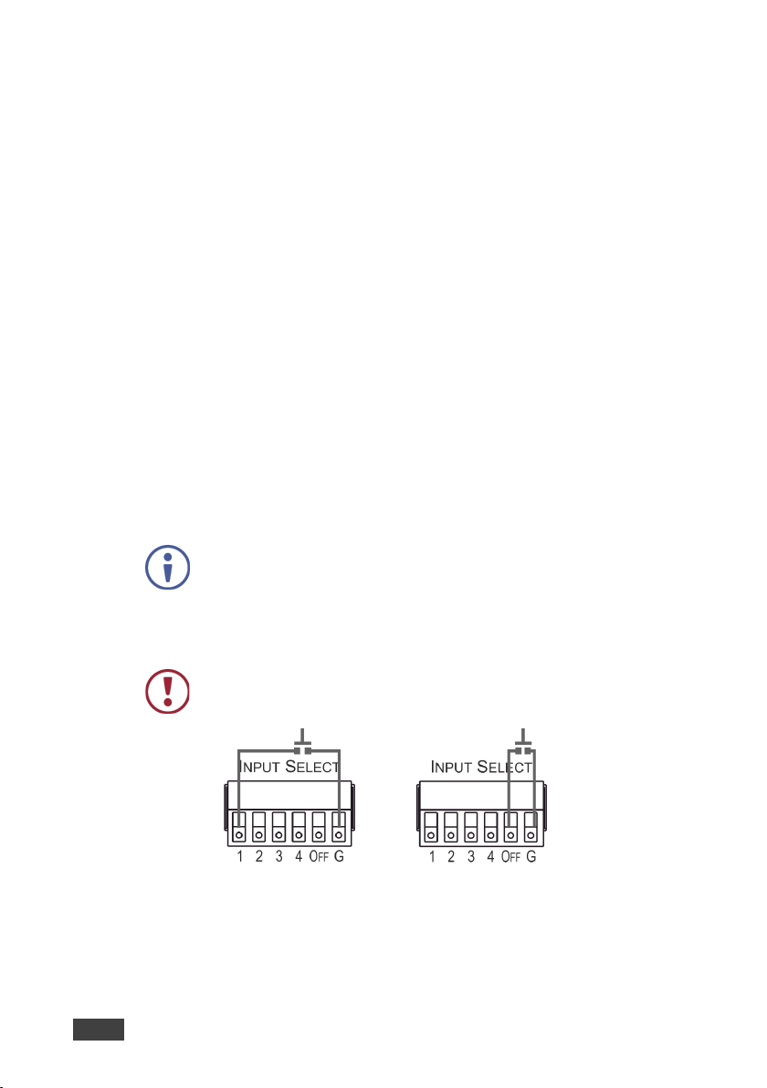
6.2 Switching via the Terminal Block Connector
The INPUT SELECT terminal block connector includes five input pins and a G pin
for selecting an input:
• 1 – Switch to Input 1
• 2 – Switch to Input 2
• 3 – Switch to Input 3
• 4 – Switch to Input 4
• OFF – Mutes the HDMI output
For example, you may override (equivalent to pressing a different input button) the
presently routed input by using the remote control contact closure. To do so,
connect the appropriate input number (input 1, 2, 3 or 4) pin on the REMOTE
terminal block connector to the G (Ground) pin, as Figure 4 illustrates.
To disconnect the inputs from the output, connect the OFF pin on the REMOTE
terminal block connector to the G (Ground) pin, as Figure 4 illustrates.
When in the manual mode (AUTO front panel LED is off), you can
switch an input to the output using the front panel INPUT SELECT
button.
Note that unless the connection is permanent, the VS-411UHD
DO NOT Connect more than one pin to the Ground pin at the same
time.
momentarily connect the INPUT
SELECT 1 (2, 3, 4) pin to the G pin
Figure 4: Connecting the Contact Closure Remote Control Pins
16 VS-411UHD - Controlling the VS-411UHD
output, momentarily connect the
INPUT SELECT OFF pin to the G pin
Page 23
Connect this pin on the
terminal block connector
To this pin on the
9-pin D-sub Co nnector
Tx
Pin 2
Rx
Pin 3
6.3 Using the RC-IR3 Remote Control Transmitter with the VS-411UHD
You can control the VS-411UHD via the Kramer RC-IR3 Remote Control
Transmitter.
To switch an input to the output:
• Press key 1 (2, 3, 4) to switch INPUT 1 (2, 3, 4) to the output
To mute audio and video on the output:
• Press the OFF key to disconnect the output
The IR LED behaves as follows:
• When the device is powered on, the IR LED turns on for a short time and
then turns off
• Before finding the sink, the LED is off
• After finding the sink, the LED is on
• When receiving information, the LED flashes
6.4 Connecting to the VS-411UHD via RS-232
VS-411UHD - Controlling the VS-411UHD
Connect the RS-232 Terminal block connector on the product to the RS-232 9-pin
D-sub port on your PC/controlled device to control the VS-411UHD, as shown in
Figure 5
:
GND Pin 5
Figure 5: RS-232 Pinout
17
Page 24

6.5 Performing a Factory Reset
Factory reset returns all the parameters of the device to their factory default
settings.
To perform a factory reset:
1. Disconnect device power.
2. Press and hold INPUT 1 while reconnecting device power.
All indicators flash while resetting to the factory default parameters.
3. When all the lights turn off the reset is complete.
18 VS-411UHD - Controlling the VS-411UHD
Page 25
INPUTS:
4 HDMI connectors, 4 unbalanced stereo audio on 3.5mm mini
Impedance: 10kΩ.
OUTPUTS:
1 HDMI connector, 1 balanced stereo audio on 5-pin terminal block
PORTS:
1 RS-232 on a 3-pin terminal block, 1 mini USB for programming
COMPLIANCE WITH HDMI
HDMI 1.4, Deep Color, 3D, ARC, up to 7.1 uncompressed audio
SUPPORTED RESOLUTIONS:
Up to 4K x 2K, 4K@60Hz (4:2:0)
CONTROLS:
Front panel buttons, contact closure, IR, RS-232 Protocol 3000
SOFTWARE SUPPORT:
Protocol 3000, EDID Designer, K-Upload
POWER CONSUMPTION:
5V DC, 500mA
OPERATING TEMPERATURE:
0° to +40°C (32° to 104°F)
STORAGE TEMPERATURE:
-40° to +70°C (-40° to 158°F)
HUMIDITY:
10% to 90%, RHL non-condensing
DIMENSIONS:
21.5cm x16.3cm x 4.4cm (8.4" x 6.4" x 7.2") W, D, H
WEIGHT:
0.89kg (1.96lbs) approx.
SHIPPING DIMENSIONS:
31.5cm x 21.2cm x 7.2cm (12.4" x 8.4" x 2.8") W, D, H
SHIPPING W EIGHT:
1.49kg (3.28lbs) approx.
INCLUDED ACCESSORIES:
Power adapter, IR remote control
OPTIONS:
RK-1 19” rack adapter
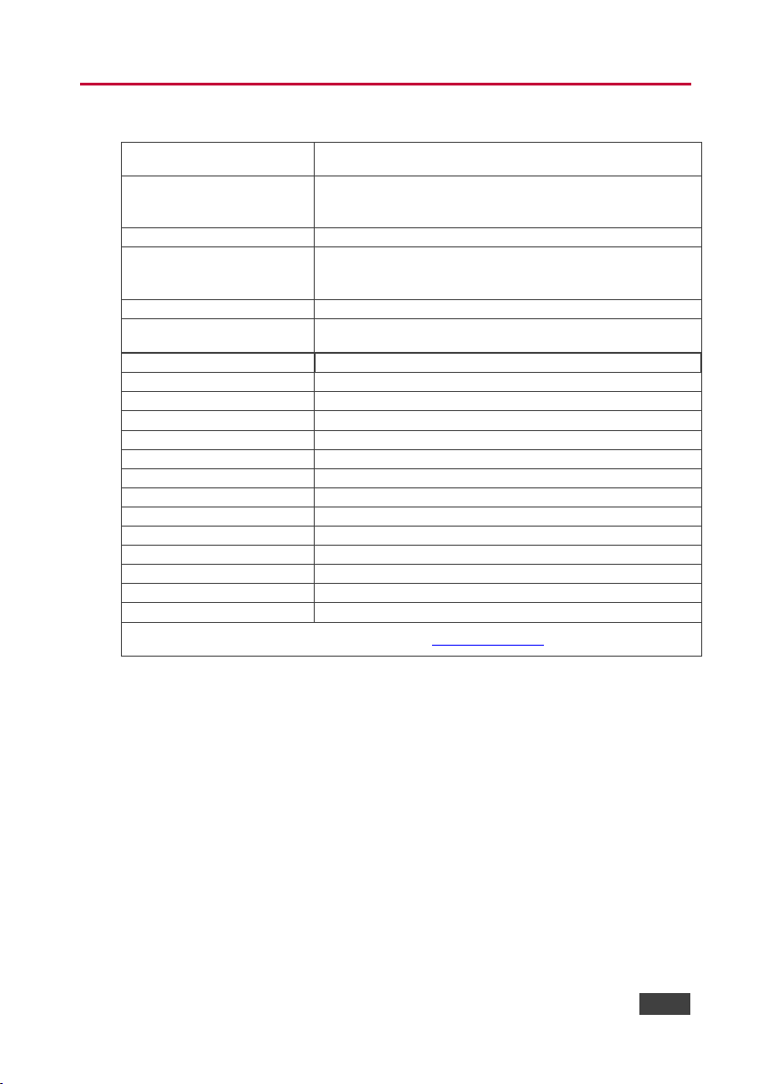
7 Technical Specifications
jacks
ANALOG AUDIO
UNBALANCED INPUT:
Nominal level: 316mVRMS,
Maximum level: 1VRMS,
ANALOG AUDIO BALANCED
OUTPUT:
STANDARD:
MAX. DATA RATE: 8.91Gbps (2.97Gbps per graphic channel)
Specifications are subject to change without notice at www.kramerav.com
Nominal level: 316mVRMS,
Maximum level: 1VRMS,
Impedance: 150Ω.
channels, CEC
VS-411UHD - Technical Specifications
19
Page 26

Resolution
Refresh Rate
640 x 480p (59.95Hz is available on
720 x x480p
60Hz
720 x x576p
50Hz
800 x 600p
85Hz; 75Hz; 72Hz; 60Hz
848 x 480p
60Hz
852 x 480p (available on quantum 780B)
60Hz
1024 x 768p
85Hz; 75Hz; 70Hz; 60Hz
1280 x 960
60Hz
1280 x 1024p
75Hz; 60Hz
1280 x 768p (available on quantum 780B)
60Hz
1280x800p
60Hz
1920 x 1080p
50Hz; 60Hz; 30Hz; 24Hz;
1920 x 1080p
60Hz;
1920 x 1080i
50Hz; 60Hz;
1600 x 1200p
60Hz
1920 x 1200p
1600 x 900p
60Hz
1152 x 864p
75Hz
1440 x 900p
60Hz
1680 x 1050p
60Hz
1360 x 768p
60Hz
1366 x 768
60Hz; 50Hz
1400 x 1050p
60Hz
720 x 480i (available on quantum 780B)
30Hz
3840 x 2160
30Hz; 25Hz; 24Hz; 60Hz 4:2:0
4096 x 2160
24Hz
8 Supported Resolutions
quantum 780B)
85Hz; 75Hz; 72Hz; 60Hz; 59.95Hz
20 VS-411UHD - Supported Resolutions
Page 27
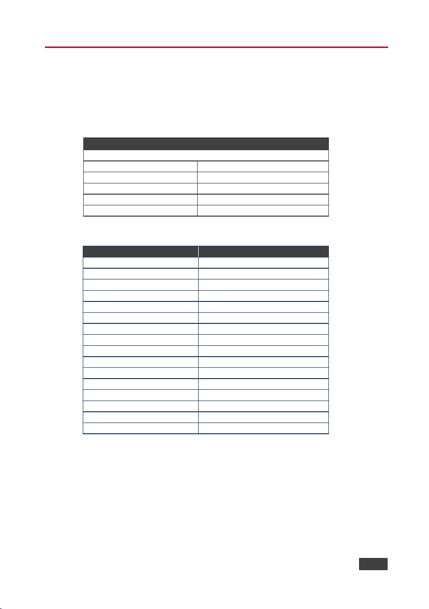
RS-232
Protocol 3000 (Default)
Baud Rate
9600
Data Bits
8
Stop Bits
1
Parity
None
Command Format
ASCII
Parameter
Value
Out HDCP mode
Follow
Communication Format
KMR3000 (KMR device)
Close Output 5v Time
15sec
Current Input Source Port
Input port 1
Manual/Auto Switch Mode
Auto mode
Pr/Lc Switch Mode
Priority mode
ARC/De-embed Audio Out
DE-embed audio out
RS-232 Connection
CPU
Input Port HDCP
All ON
Kramer 3000 Model Name
‘V', 'S', '-', '4', '1', '1', 'U', 'H', 'D'
EDID
Default
USB for Virtual Com
Virtual Com
IP Address
192.168.1.39
Mask Number
255.255.0.0
Gateway Number
192.168.0.254
DHCP
Disabled (OFF)
9 Default Settings
The VS-411UHD has the following default settings for communication, first power
on and EDID.
9.1 Default Communication Settings
9.2 First Power On Default Settings
VS-411UHD - Default Settings
21
Page 28

9.3 Default EDID
Monitor
Model name............... VS-411UHD
Manufacturer............. KMR
Plug and Play ID......... KMR03ED
Serial number............ 1
Manufacture date......... 2015, ISO week 20
Filter driver............ None
-------------------------
EDID revision............ 1.3
Input signal type........ Digital (HDMI-a)
Color bit depth.......... Undefined
Display type............. RGB color
Screen size.............. 700 x 390 mm (31.5 in)
Power management......... Not supported
Extension blocs.......... 1 (CEA-EXT)
-------------------------
DDC/CI................... Not supported
Color characteristics
Default color space...... Non-sRGB
Display gamma............ 2.20
Red chromaticity......... Rx 0.640 - Ry 0.341
Green chromaticity....... Gx 0.286 - Gy 0.610
Blue chromaticity........ Bx 0.146 - By 0.069
White p oint (default).... Wx 0.284 - Wy 0.293
Additional descriptors... None
Timing characteristics
Horizontal scan range.... 31-94kHz
Vertical scan range...... 50-85Hz
Video bandwidth.......... 170MHz
CVT standard............. Not supported
GTF standard............. Not supported
Additional descriptors... None
Preferred timing......... Yes
Native/preferred timing.. 1280x720p at 60Hz
Modeline............... "1280x720" 74.250 1280 1390 1430 1650 720 725 730 750 +hsync +vsync
Detailed timing #1....... 1920x1080p at 60Hz (16:9)
Modeline............... "1920x1080" 148.500 1920 2008 2052 2200 1080 1084 1089 1125 +hsync +vsync
Standard timings supported
720 x 400p at 70Hz - IBM VGA
720 x 400p at 88Hz - IBM XGA2
640 x 480p at 60Hz - IBM VGA
640 x 480p at 67Hz - Apple Mac II
640 x 480p at 72Hz - VESA
640 x 480p at 75Hz - VESA
800 x 600p at 56Hz - VESA
800 x 600p at 60Hz - VESA
800 x 600p at 72Hz - VESA
800 x 600p at 75Hz - VESA
832 x 624p at 75Hz - Apple Mac II
1024 x 768i at 87Hz - IBM
1024 x 768p at 60Hz - VESA
1024 x 768p at 70Hz - VESA
1024 x 768p at 75Hz - VESA
1280 x 1024p at 75Hz - VESA
1152 x 870p at 75Hz - Apple Mac II
1280 x 720p at 60Hz - VESA STD
1280 x 800p at 60Hz - VESA STD
1440 x 900p at 60Hz - VESA STD
1280 x 960p at 60Hz - VESA STD
1280 x 1024p at 60Hz - VESA STD
1400 x 1050p at 60Hz - VESA STD
1680 x 1050p at 60Hz - VESA STD
1600 x 1200p at 60Hz - VESA STD
22 VS-411UHD - Default Settings
Page 29

EIA/CEA-861 Information
Revision number.......... 3
IT underscan............. Not supported
Basic audio.............. Supported
YCbCr 4:4:4.............. Not supported
YCbCr 4:2:2.............. Not supported
Native formats........... 1
Detailed timing #1....... 720x480p at 60Hz (4:3)
Modeline............... "720x480" 27.000 720 736 798 858 480 489 495 525 -hsync -vsync
Detailed timing #2....... 1920x1080i at 60Hz (16:9)
Modeline............... "1920x1080" 74.250 1920 2008 2052 2200 1080 1084 1094 1124 interlace +hsync
+vsync
Detailed timing #3....... 1920x1080i at 50Hz (16:9)
Modeline............... "1920x1080" 74.250 1920 2448 2492 2640 1080 1084 1094 1124 interlace +hsync
+vsync
Detailed timing #4....... 1280x720p at 60Hz (16:9)
Modeline............... "1280x720" 74.250 1280 1390 1430 1650 720 725 730 750 +hsync +vsync
Detailed timing #5....... 1280x720p at 50Hz (16:9)
Modeline............... "1280x720" 74.250 1280 1720 1760 1980 720 725 730 750 +hsync +vsync
CE video identifiers (VICs) - timing/formats supported
720 x 576p at 50Hz - EDTV (4:3, 16:15)
1280 x 720p at 50Hz - HDTV (16:9, 1:1)
1920 x 1080i at 60Hz - HDTV (16:9, 1:1)
1920 x 1080i at 50Hz - HDTV (16:9, 1:1)
1280 x 720p at 60Hz - HDTV (16:9, 1:1) [Native]
1920 x 1080p at 60Hz - HDTV (16:9, 1:1)
1920 x 1080p at 50Hz - HDTV (16:9, 1:1)
NB: NTSC refresh rate = (Hz*1000)/1001
CE audio data (formats supported)
LPCM 2-channel, 24-bits at 44/48 kHz
CE speaker allocation data
Channel configuration.... 2.0
Front left/right......... Yes
Front LFE................ No
Front center............. No
Rear left/right.......... No
Rear center.............. No
Front left/right center.. No
Rear left/right center... No
Rear LFE................. No
CE vendor specific data (VSDB)
IEEE registration number. 0x000C03
CEC physical address..... 1.0.0.0
Maximum TMDS clock....... 165MHz
Report information
Date generated........... 25/07/2016
Software revision........ 2.70.0.989
Data source.............. Real-time 0x0071
Operating system......... 6.1.7601.2.Service Pack 1
Raw data
00,FF,FF,FF,FF,FF,FF,00,2D,B2,ED,03,01,00,00,00,14,19,01,03,80,34,20,78,E2,B3,25,AC,51,30,B4,26,
10,50,54,FF,FF,80,81,8F,81,99,A9,40,61,59,45,59,31,59,71,4A,81,40,01,1D,00,72,51,D0,1E,20,6E,28,
55,00,07,44,21,00,00,1E,00,00,00,FF,00,32,39,35,2D,38,38,33,34,35,30,31,30,30,00,00,00,FC,00,56,
53,2D,34,31,31,55,48,44,00,00,00,00,00,00,00,FD,00,38,4C,1E,53,11,00,0A,20,20,20,20,20,20,01,41,
02,03,1B,C1,23,09,07,07,48,10,05,84,03,02,07,16,01,65,03,0C,00,10,00,83,01,00,00,02,3A,80,18,71,
38,2D,40,58,2C,45,00,07,44,21,00,00,1E,01,1D,80,18,71,1C,16,20,58,2C,25,00,07,44,21,00,00,9E,01,
1D,00,72,51,D0,1E,20,6E,28,55,00,07,44,21,00,00,1E,8C,0A,D0,8A,20,E0,2D,10,10,3E,96,00,07,44,21,
00,00,18,00,00,00,00,00,00,00,00,00,00,00,00,00,00,00,00,00,00,00,00,00,00,00,00,00,00,00,00,77
VS-411UHD - Default Settings
23
Page 30
10 Protocol 3000
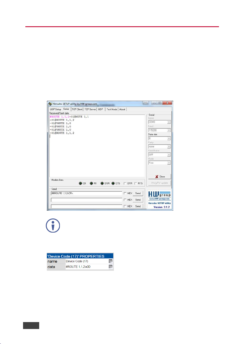
The VS-411UHD can be operated using the Kramer Protocol 3000 serial
commands. The command framing varies according to how you interface with the
VS-411UHD. For example, a basic video input switching command that routes a
layer 1 video signal to HDMI out 1 from HDMI input 2 (ROUTE 1,1,2), is entered
as follows:
• Terminal communication software, such as Hercules:
The framing of the command varies according to the terminal
communication software. This command is used for demonstration
purposes only and its syntax may vary per device.
• K-Touch Builder (Kramer software):
• As a driver in K-Config (Kramer configuration software):
24 VS-411UHD - Protocol 3000
Page 31
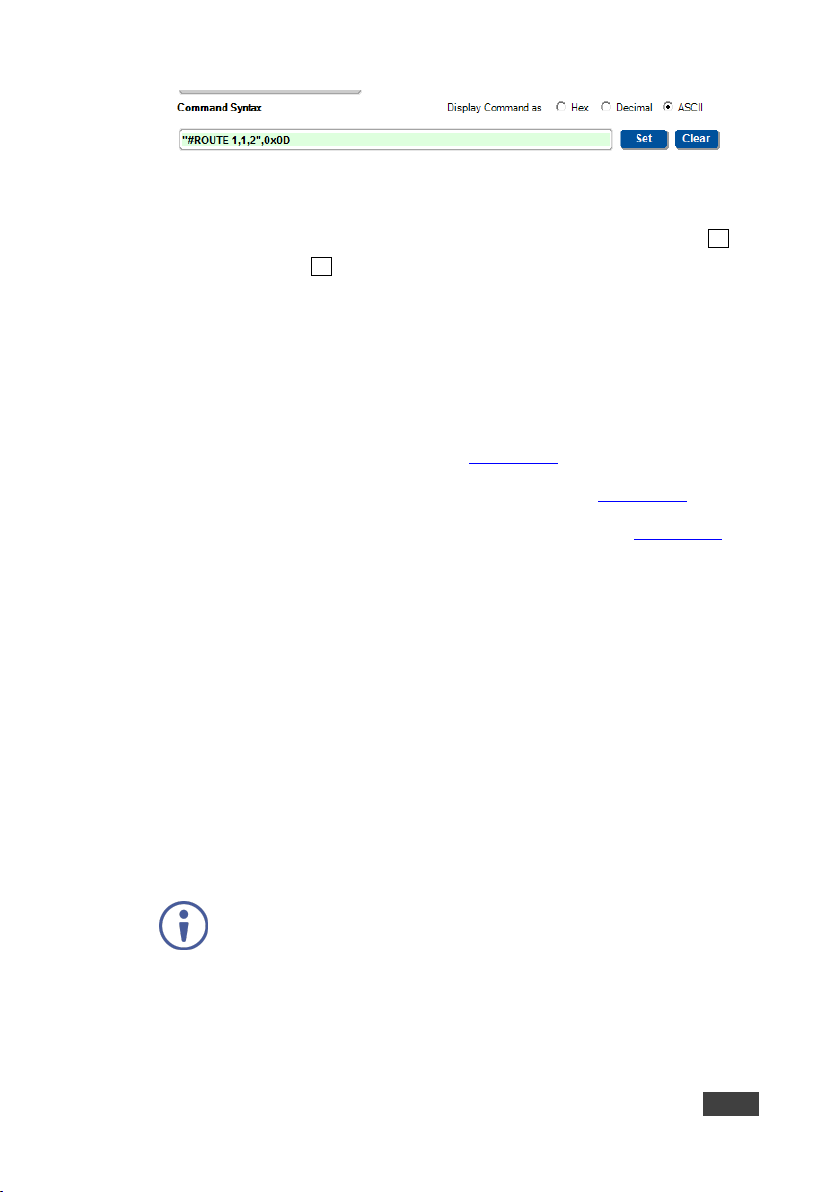
You can enter commands directly using terminal communication software (e.g.,
Hercules) by connecting a PC to the serial port on the VS-411UHD. To enter CR
press the Enter key ( LF is also sent but is ignored by the command parser).
Commands sent from various non-Kramer controllers (e.g., Crestron) may require
special coding for some characters (such as, /X##). For more information, refer to
your controller’s documentation.
For more information about:
• Using Protocol 3000 commands, see Section 10.1
• General syntax used for Protocol 3000 commands, see Section 10.2
• Protocol 3000 commands available for the VS-411UHD, see Section 10.3
10.1 Understanding Protocol 3000
Protocol 3000 commands are structured according to the following:
• Command – A sequence of ASCII letters (A-Z, a-z and -). A command and
its parameters must be separated by at least one space.
• Parameters – A sequence of alphanumeric ASCII characters (0-9, A-Z,
a-z and some special characters for specific commands). Parameters are
separated by commas.
• Message string – Every command entered as part of a message string
begins with a message starting character and ends with a message closing
character.
A string can contain more than one command. Commands are
separated by a pipe (|) character.
The maximum string length is 64 characters.
• Message starting character:
• # – For host command/query
VS-411UHD - Protocol 3000
25
Page 32

• ~ – For device response
• Device address – K-NET Device ID followed by @ (optional, K-NET only)
• Query sign – ? follows some commands to define a query request
• Message closing character:
• CR – Carriage return for host messages (ASCII 13)
• CR LF – Carriage return for device messages (ASCII 13) and line-feed
(ASCII 10)
• Command chain separator character – Multiple commands can be
chained in the same string. Each command is delimited by a pipe character
(|). When chaining commands, enter the message starting character and the
message closing character only at the beginning and end of the string.
Spaces between parameters or command terms are ignored.
Commands in the string do not execute until the closing character is
entered. A separate response is sent for every command in the
chain.
26 VS-411UHD - Protocol 3000
Page 33
Start
Address (optional)
Body
Delimiter
#
Device_id@
Message
CR
Start
Body
Delimiter
#
CR
Start
Address
Body
Delimiter
#
Device_id@
CR
Start
Address (optional)
Body
Delimiter
~
Device_id@
Message
CR LF
Start
Address (optional)
Body
Delimiter
~
Device_id@
CR LF
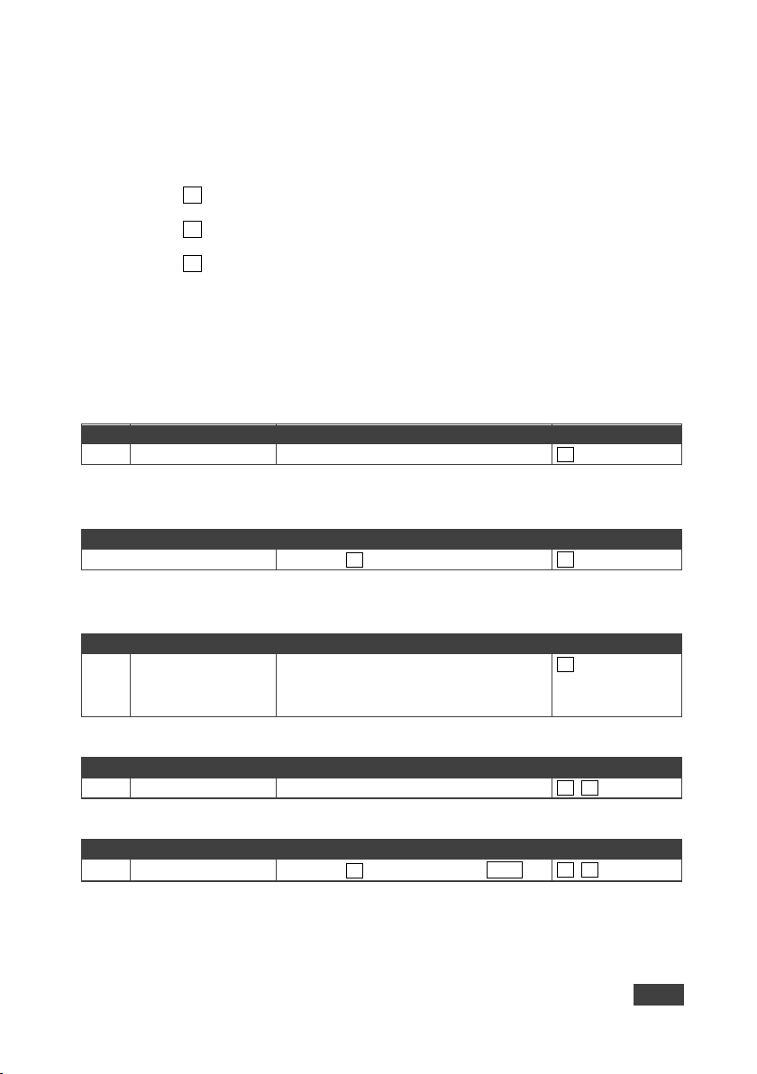
10.2 Kramer Protocol 3000 Syntax
The Kramer Protocol 3000 syntax uses the following delimiters:
• CR = Carriage return (ASCII 13 = 0x0D)
• LF = Line feed (ASCII 10 = 0x0A)
• SP = Space (ASCII 32 = 0x20)
Some commands have short name syntax in addition to long name syntax to enable
faster typing. The response is always in long syntax.
The Protocol 3000 syntax is in the following format:
• Host Message Format:
• Simple Command – Command string with only one command without
addressing:
Command SP Parameter_1,Parameter_2,…
VS-411UHD - Protocol 3000
• Command String – Formal syntax with command concatenation and
addressing:
Command_1 Parameter1_1,Parameter1_2,…|
Command_2 Parameter2_1,Parameter2_2,…|
Command_3
Parameter3_1,Parameter3_2,…|…
• Device Message Format:
• Device Long Response – Echoing command:
Command SP [Param1,Param2 …] result
27
Page 34
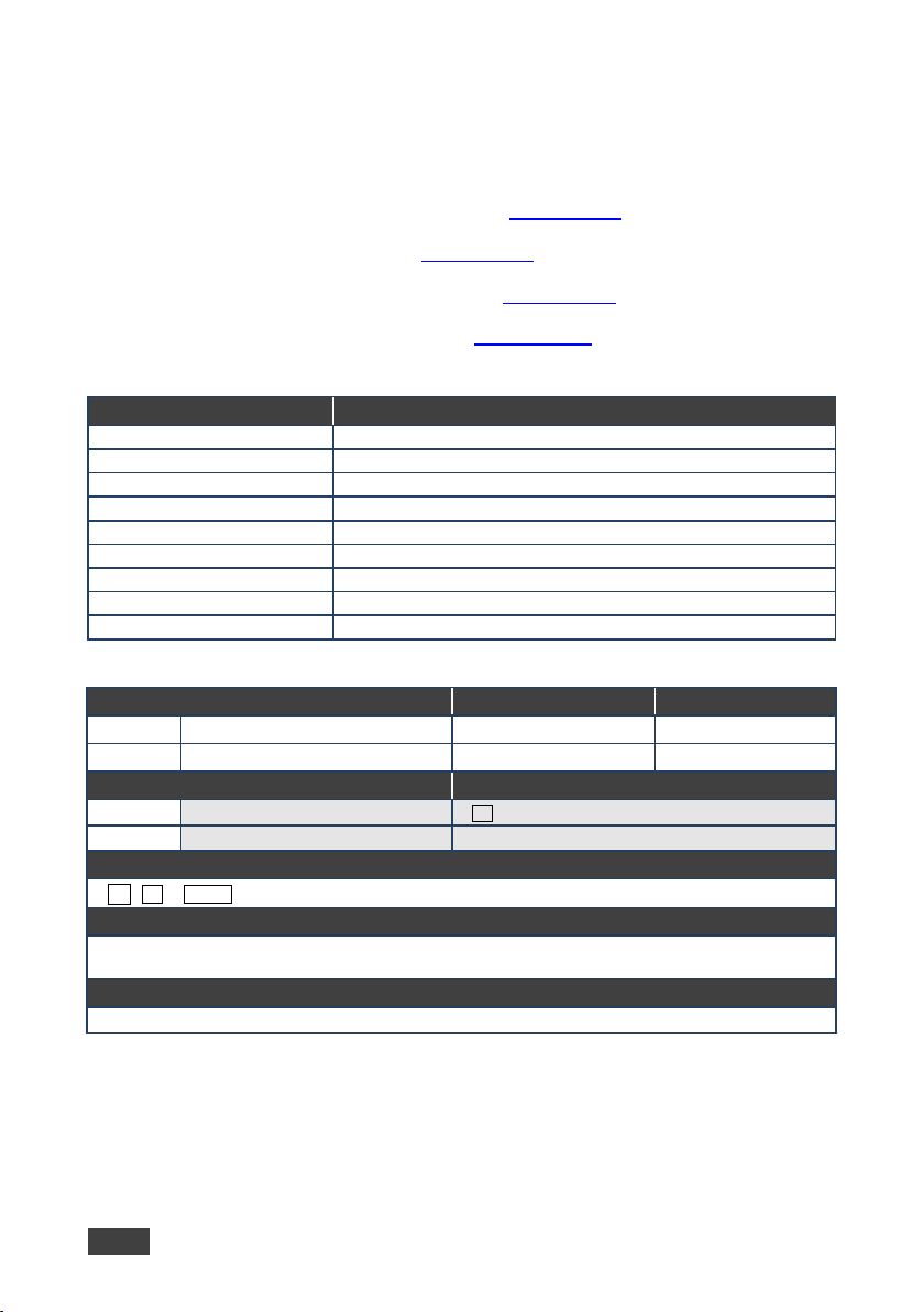
#
Protocol handshaking (system mandatory)
BUILD-DATE
Get device build date (system mandatory)
FACTORY
Reset to factory default configuration
HELP
Get command list (system mandatory)
MODEL
Get device model (system mandatory)
PROT-VER
Get device protocol version (system mandatory)
RESET
Reset device (system mandatory)
SN?
Get device serial number (system mandatory)
VERSION
Get device firmware version (system mandatory)
#
#CR
Get: - -
~nn@SP OKCR LF
“#”,0x0D
10.3 Protocol 3000 Commands
This section includes the following commands:
• System Commands Mandatory (see Section 10.3.1
)
• System Commands (see Section 10.3.2)
• Switching/Routing Commands (see Section 10.3.3)
• EDID Handling Commands (see Section 10.3.4)
10.3.1 System Commands - Mandatory
Command Description
10.3.1.1 #
Functions Permission Transparency
Set:
Get:
Description Syntax
Set: Protocol handshaking
-
End User Public
- -
Response
Notes
Validates the Protocol 3000 connection and gets the machine number
Step-in master products use this command to identify the availability of a device
K-Config Example
28 VS-411UHD - Protocol 3000
Page 35
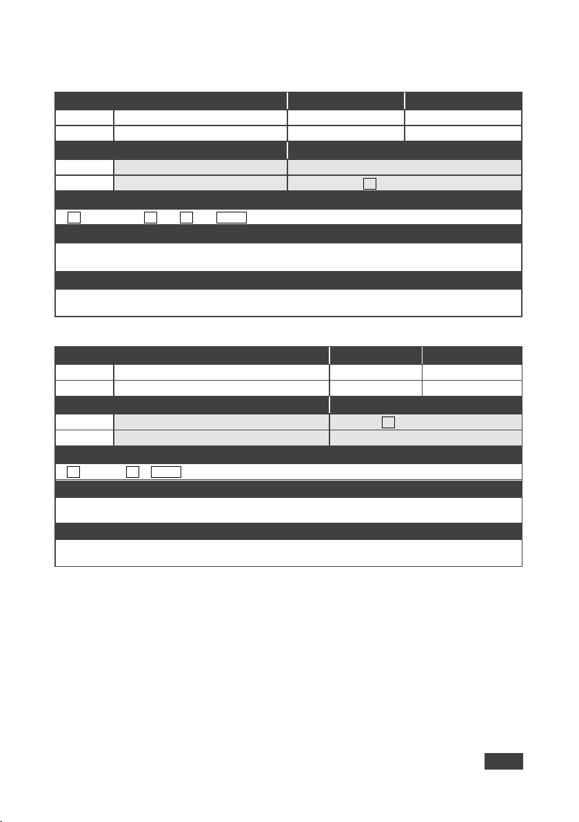
BUILD-DATE
Get: - -
-
Set:
Get:
Get device build date
#BUILD-DATE?CR
~nn @BUILD-DATESP
CR LF
hh:mm:ss
“#BUILD-DATE?”,0x0D
Set:
FACTORY
End User
Public
-
Set:
Reset device to factory defaults configuration
#FACTORYCR
~nn @FACTORYSPOK CR LF
Your device may require powering off and powering on for the changes to take effect.
K-Config Example
Reset the device to its factory default configuration:
“#FACTORY”,0x0D
10.3.1.2 BUILD-DATE
Functions Permission Transparency
Set:
Description Syntax
Response
dateSPtime
Parameters
date – Format: YYYY/MM/DD where YYYY = Year, MM = Month, DD = Day
time – Format:
K-Config Example
Read the device build date:
where hh = hours, mm = minutes, ss = seconds
10.3.1.3 FACTORY
Functions Permission Transparency
End User -
Get:
Description Syntax
Get: - -
Response
Notes
This command deletes all user data from the device. The deletion can take some time.
VS-411UHD - Protocol 3000
- -
29
Page 36
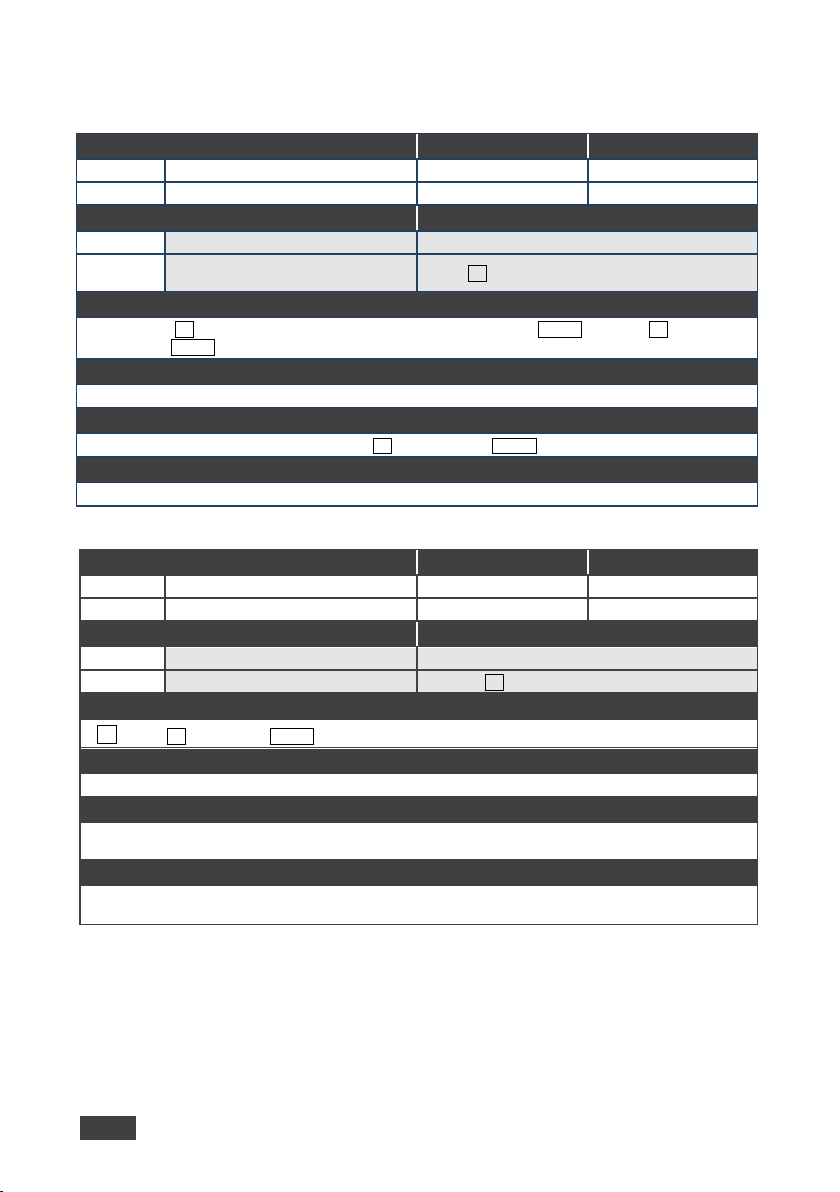
Get:
HELP
End User
Public
Get command list or help for specific
CR LF
– name of a specific command
HELPSP COMMAND_NAMECR LF
“#HELP”,0x0D
Set: - - - Get:
MODEL?
End User
Public
Set: - -
#MODEL?CR
@MODELSP
CR LF
This command identifies equipment connected to Step-in master products and notifies of identity changes
“#MODEL?”,0x0D
10.3.1.4 HELP
Functions Permission Transparency
Set:
-
- -
Description Syntax
Set: - -
Get:
command
#HELPCR
Response
1. Multi-line: ~ nn@Device available protocol 3000 commands:CR LF command, SP
command...
Parameters
COMMAND_NAME
Notes
To get help for a specific command use:
K-Config Example
10.3.1.5 MODEL
Functions Permission Transparency
Description Syntax
Get: Get device model
Response
~nn
model_name
Parameters
model_name – String of up to 19 printable ASCII chars
Notes
to the connected equipment. The Matrix saves this data in memory to answer REMOTE-INFO requests
K-Config Example
Get device model:
30 VS-411UHD - Protocol 3000
Page 37
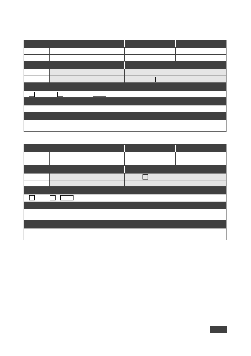
-
Get:
PROT-VER?
End User
Public
Set: - -
Get:
Get protocol version
PROT-VER?CR
nn@PROT-VER SP
CR LF
version – Format: XX.XX where X is a decimal digit
Get the protocol version:
“#PROT-VER?”,0x0D
RESET
Get: - -
-
Set:
Reset device
#RESETCR
Get: - -
~nn @RESETSPOK CR LF
running this command. If the port was locked, disconnect and reconnect the cable to reopen the port.
K-Config Example
Reset the device:
“#RESET”,0x0D
10.3.1.6 PROT-VER
Functions Permission Transparency
Set:
Description Synt ax
Response
~
Parameters
K-Config Example
3000:version
10.3.1.7 RESET
Functions Permission Transparency
Set:
Description Synt ax
Response
- -
Administrator Public
Notes
To avoid locking the port due to a USB bug in Windows, disconnect USB connections immediately after
VS-411UHD - Protocol 3000
31
Page 38
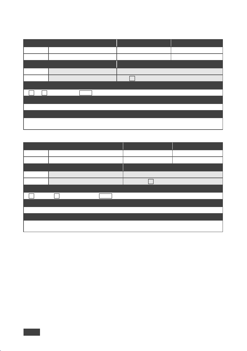
Get:
SN?
End User
Public
Get:
Get device serial number
#SN?CR
~nn @SNSP
CR LF
serial_number
Get device serial number:
“#SN?”,0x0D
Set: - - - Get:
VERSION?
End User
Public
Set: - -
Get:
Get version number
#VERSION?CR
~nn @VERSIONSP
CR LF
firmware_version – format: XX.XX.XX.XXXX where the digits group are: major, minor, build, revision
K-Config Example
Get the firmware version number:
“#VERSION?”,0x0D
10.3.1.8 SN
Functions Permission Transparency
Set:
-
- -
Description Syntax
Set: - -
Response
serial_number
Parameters
– 14 decimal digits, factory assigned
K-Config Example
10.3.1.9 VERSION
Functions Permission Transparency
Description Syntax
Response
firmware_version
Parameters
32 VS-411UHD - Protocol 3000
Page 39
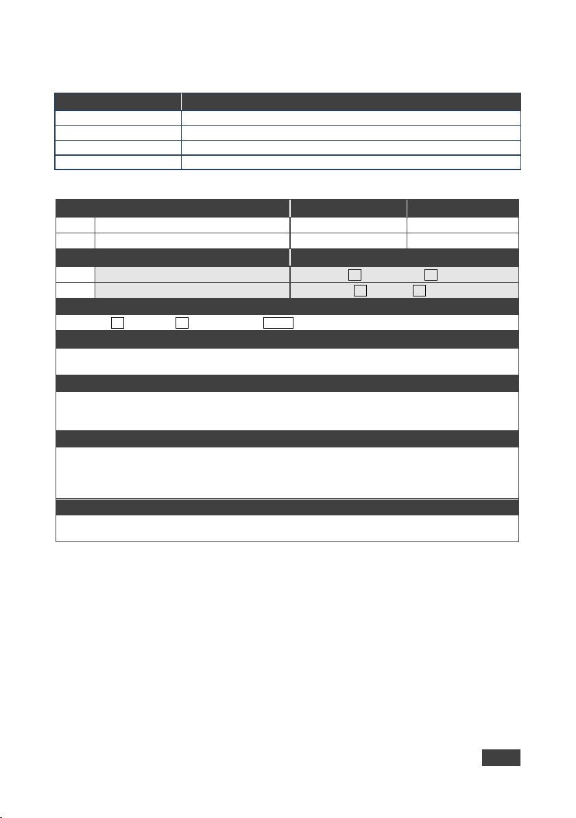
HDCP-MOD
Set/get HDCP mode
HDCP-STAT?
Get HDCP signal status
LOCK-FP
Set/get front panel lock
UART
Set/get comm port configuration
Set:
HDCP-MOD
Administrator
Public
HDCP-MOD?
Set:
Set HDCP mode
#HDCP-MODSP inp_id,modeCR
#HDCP-MOD?SP stage_idCR
Response
nn@HDCP-MOD SP
CR LF
mode - HDCP mode: 0 (HDCP OFF), 1 (HDCP ON)
Response triggers
control device (button press, device menu and similar) or HDCP mode change d
Set HDCP working mode on device input:
HDCP support changes following detected sink – MIRROR OUTPUT
K-Config Example
Set HDCP mode on HDMI 1 on:
“#HDCP-MOD 1,1”,0x0D
10.3.2 System Commands
Command Description
10.3.2.1 HDCP-MOD
Functions Perm ission Transparency
Get:
Description Synt ax
Get: Get HDCP mode
Set / Get: ~
Parameters
inp_id - input number: 1.. (max number of inputs)
Response is sent to the com port from which the Set (before execution) / Get command was received
Response is sent to all com ports after execution if HDCP-MOD was set by any other external
Notes
HDCP supported – HDCP ON [default]
HDCP not supported – HDCP OFF
stage_id,mode
End User System
VS-411UHD - Protocol 3000
33
Page 40
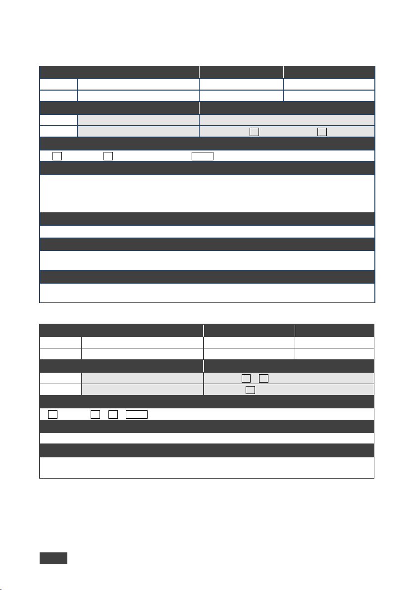
Get:
HDCP-STAT?
End User
Public
Get:
Get HDCP signal status
#HDCP-STAT?SP stage,stage_idCR
~ nn @HDCP-STATSP
CR LF
Output stage (1) – get the HDCP signal status of the sink device connected to HDMI Out
Get the HDCP input signal status of the source device connected to Input 1 HDMI:
“#HDCP-STAT? 0,1”,0x0D
Set:
LOCK-FP
End User
-
LOCK-FP?
Set:
Lock front panel
#LOCK-FPSP P1CR
#LOCK-FP?CR
nn@LOCK-FP SPP1SP OKCR LF
P1 – 0 (No) 1 (Yes)
“#LOCK-FP 1”,0x0D
10.3.2.2 HDCP-STAT
Functions Permission Transparency
Set: - - -
Description Syntax
Set: - -
Response
stage,stage_id,mode
Parameters
stage – 0 (input), 1 (output)
stage_id – for input stage: 1 (Input 1 HDMI), 2 (Input 2 HDMI), for output stage: 1 (HDMI Out)
actual_status – HDCP signal encryption status: 0 (Off), 1 (On), 2 (Follow input), 3 (Mirror output –
MAC mode)
Response Triggers
A response is sent to the comm port from which the Get command was received
Notes
Input stage (0) – get the HDCP signal status of the source device connected to the specified input
K-Config Example
10.3.2.1 LOCK-FP
Functions Perm ission Transparency
Get:
Description Syntax
Get: Get front panel lock state
Response
~
Parameters
K-Config Example
Lock the front panel:
34 VS-411UHD - Protocol 3000
End User System
Page 41
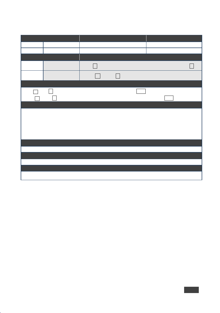
UART
Get:
UART?
End User
Public
Set comm port
configuration
#UART
Get comm port
configuration
#UART?
~ nn @UART?␠
␍␊
COM_Num – 1 (RS-232 terminal block)
serial1_type - 232
K-Config Example
Set the RS-232 terminal block to 115200 baud rate,8 data bits, no parity,1 stop bit:
“#UART 1,115200,8,N,1”,0x0D
10.3.2.1 UART
Command Name Permission Transparency
Set:
Description Syntax
Set:
Administrator Public
␠Com_Num,Baud_Rate,Data_Bit,Parity,Stop_Bit ␍
Get:
Response
Set: ~ nn @UART␠ComNum,BaudRate,DataBit,Parity,StopBit ␍␊
Get:
Parameters
baud_rate - 9600 - 115200
data_bit - 7,8
parity - 0 (No), 1 (Odd), 2 (Even), 3 (Mark), 4 (Space)
stop_bit - 1,2
Response Triggers
Notes
ComNum,BaudRate,DataBit,Parity,StopBit,SerialType
␠Com_Num ␍
VS-411UHD - Protocol 3000
35
Page 42
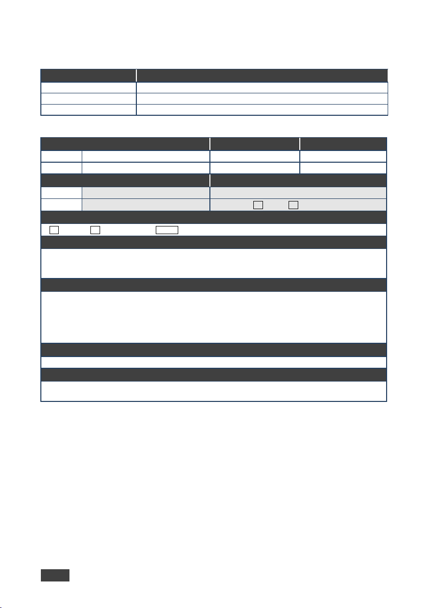
DISPLAY?
Get output HPD status
MTX-MODE
Set/get auto-switch mode
VID
Set/get video switch state
Get
DISPLAY?
End User
Public
Get:
Get output HPD status
#DISPLAY?SP
CR
~nn @DISPLAYSP
CR LF
and valid)
After every change in output HPD status form Off to On and all parameters (new EDID, etc.) are stable and
valid (2)
“#DISPLAY? 1”,0x0D
10.3.3 Switching Commands
Command Description
10.3.3.1 DISPLAY
Functions Perm ission Transparency
Set: - - -
Description Syntax
Set: - -
out_id
Response
out_id,status
Parameters
out_id – 1 (HDMI Out)
status – HPD status according to signal validation : 0 (Off), 1 (On), 2 (On and all parameters are stable
Response Triggers
A response is sent to the comm port from which the Get was received, after command execution and:
After every change in output HPD status from On to Off (0)
After every change in output HPD status from Off to On (1)
Notes
K-Config Example
Get the output HPD status of HDMI Out:
36 VS-411UHD - Protocol 3000
Page 43
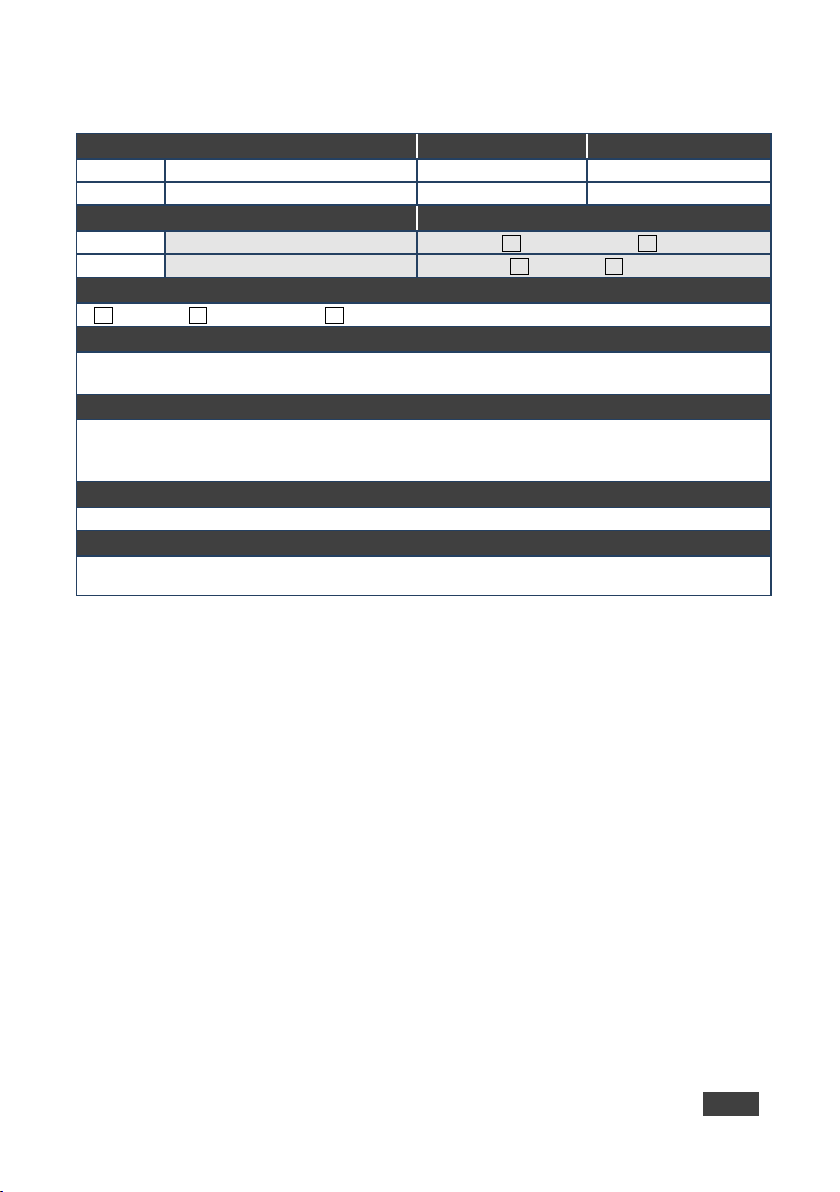
MTX-MODE
Get:
MTX-MODE?
End User
Public
#MTX-MODESP
CR
#MTX-MODE?SP output_idCR
~nn @MTX-MODESP
CR
output_id – 1 (HDMI Out)
Set the auto switch mode of HDMI Out to last connected input:
“#MTX-MODE 1,2”,0x0D
10.3.3.1 MTX-MODE
Functions Permission Transparency
Set:
Description Syn tax
Set: Set auto-switch mode
Get : Get auto-switch mode
Response
output_id,mode
Parameters
mode – 0 (manual), 1 (auto priority), 2 (auto last connected)
Response Triggers
After execution, a response is sent to the comm port from which the Set/Get was received
After execution, a response is sent to all comm ports if MTX-MODE was set by any other external control
device (button press, WEB, device menu and similar)
Notes
Not recommended for new devices
K-Config Example
End User Public
output_id,mode
VS-411UHD - Protocol 3000
37
Page 44
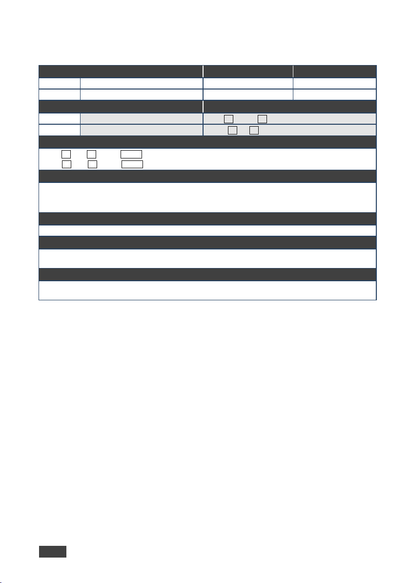
VID
Get:
VID?
End User
Public
#VIDSP
CR
#VID?SP outCR
~nn @VID SP
CR LF
The GET command identifies input switching on Step-in clients
New Step-in modules support the ROUTE command
Set the video switch state of HDMI Out to HDMI INPUT 1:
“#VID 1>1”,0x0D
10.3.3.2 VID
Functions Permission Transparency
Set:
Description Synta x
Set: Set video switch state
Get: Get video switch state
Response
Set: ~nn @VIDSPin>out CR LF
Get:
in>out
Parameters
in – 0 (disconnect output), 1 (Input 1 HDMI), 2 (Input 2 HDMI)
> – Connection character between in and out parameters
out – 1 (HDMI Out), * (all outputs)
Response Triggers
Notes
K-Config Example
End User Public
in>out
38 VS-411UHD - Protocol 3000
Page 45
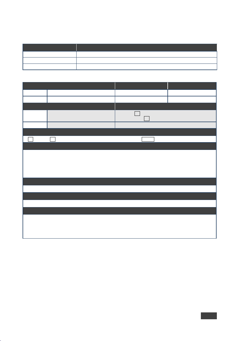
CPEDID
Copy EDID data from the output to the input EEPROM
GEDID
Set/get EDID data
LDEDID
Load EDID data
Set:
CPEDID
End User
Public
Get: - -
-
#CPEDIDSP
CR
Get: - -
~nn @CPEDIDSP
CR LF
0x3
0x4
Copy the EDID data from the HDMI Out output (EDID source) to the Input 1 HDMI:
“#CPEDID 2,1,0,0x2”,0x0D
10.3.4 EDID Handling Commands
Command Description
10.3.4.1 CPEDID
Functions Permission Transparency
Description Syntax
Set:
Response
Parameters
src_type – EDID source type (usually output): 1 (output), 2 (default EDID)
src_id – for output source: 1 (HDMI Out), for default EDID source: 1 (default ED ID)
dst_type – EDID destination type (usually input): 0 (input)
dest_bitmap – destination input to which the EDID data is copied: 0x1 (Input 1 HDMI), 0x2 (Input 2
HDMI),
Response Triggers
Response is sent to the comm port from which the Set was received (before execution)
Notes
K-Config Example
Copy EDID data from the output to
the input EEPROM
src_type,src_id,dst_type,dest_bitmap
(Input 3 HDMI),
(Input 4 HDMI)
dest_bitmap
src_type,src_id,dst_type,
“#CPEDID 1,1,0,0x1”,0x0D
Copy the EDID data from the default EDID source to Input 2 HDMI:
VS-411UHD - Protocol 3000
39
Page 46
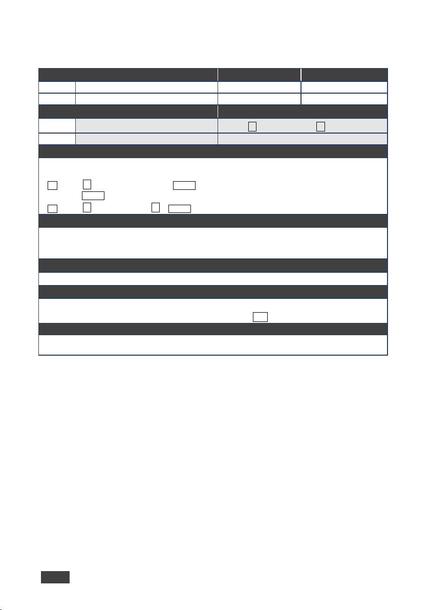
GEDID
Get: – –
–
#GEDID␠
Get: – –
Set:
~nn @GEDID␠
␠OK CR LF
K-Config Example
Set the EDID data (size x) from the HDMI Out 1:
“#GEDID 1,1”,0x0D
10.3.4.2 GEDID
Command Name Perm ission Transparency
Set:
Description Syntax
Set: Set EDID data from device
Response
Multi-line response:
~nn @GEDID␠stage,stage_id,size CR LF
EDID_dataCR LF
stage,stage_id
Parameters
stage - input/output: 0 (input), 1 (output), 2 (default EDID)
stage_id - number of chosen stage (1.. max number of inputs/outputs)
size - EDID data size. For Set, size of data to be sent from device, for Get, 0 means no EDID support
Response Triggers
Response is sent to the comm port from which the Set (before execution) / Get command was received
Notes
For Get, size=0 means EDID is not supported
For old devices that do not support this command, ~nn@ERR 002␍␊ is received
Administrator Public
stage,stage_id␍
40 VS-411UHD - Protocol 3000
Page 47
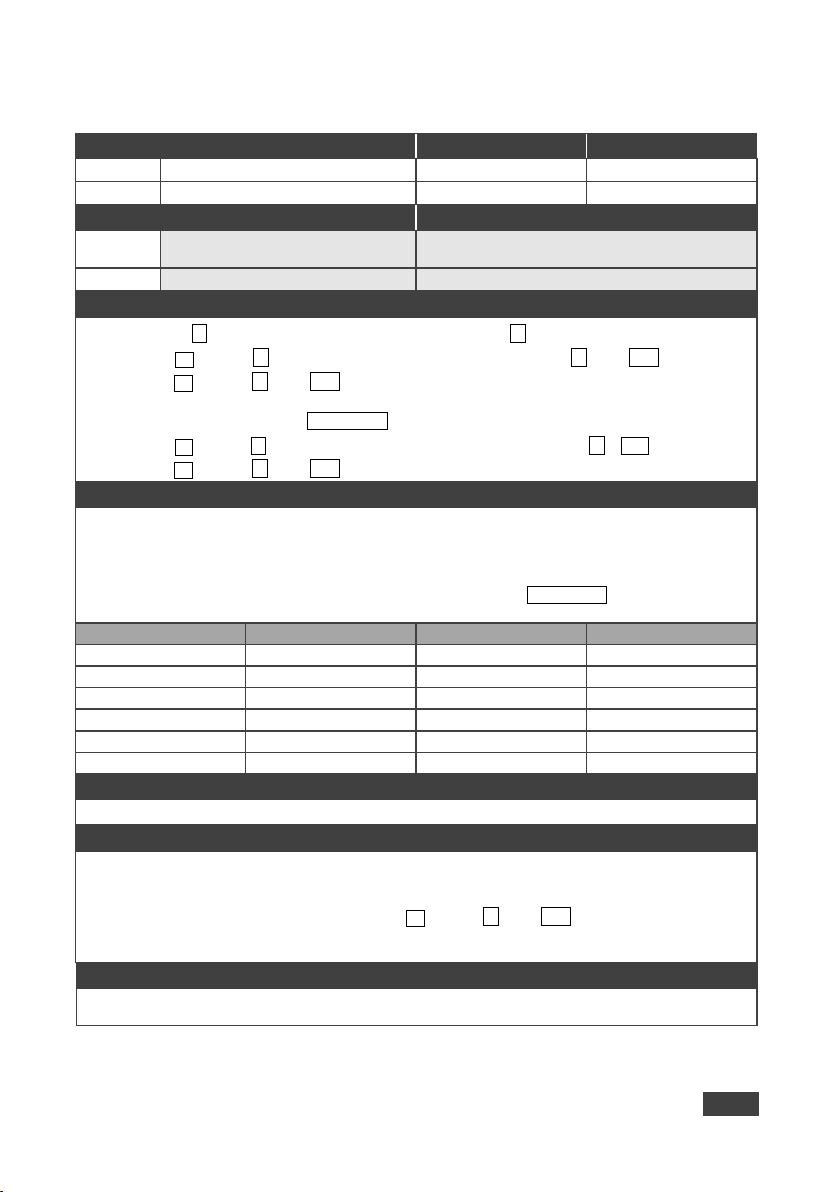
LDEDID
Write EDID data from external
Get: – –
~nn @LDEDID␠ERRnn
packets)
dest_bitmask
size
dest_bitmask
size
0x01=HDMI1
256
0x40=HDBT1
256
0x02=HDMI2
256
0x80=HDBT2
256
0x04=HDMI3
256
0x100=HDBT3
256
0x08=HDMI4
256
0x200=HDBT4
256
0x10=HDMI5
256
0x01=PC
128
0x20=HDMI6
256
When the unit receives the LDEDID command it replies with READY and enters the special EDID packet
returns to the regular protocol mode.
Write EDID to input1:
“#LDEDID 0,0x01,256,1”,0x0D
10.3.4.3 LDEDID
Command Name Permission Transparency
Set:
Get: - - -
Description S yntax
Set:
Communication Steps (Command and Response)
Step 1: #LDEDID␠ dst_type,dest_bitmask,size,safe_mode ␍
Response 1: ~ nn@LDEDID␠ dst_type,dest_bitmask,size,safe_mode ␠READY ␍␊ or
~ nn@LDEDID ␠ ERRnn␍␊
Step 2: If ready was received, send EDID_DATA
Response 2: ~ nn @LDEDID␠ dst_type, dest_bitmask, size, safe_mode␠ OK ␍␊ or
Parameters
dst_type - EDID destination type – 0 (input)
dest_bitmask – (see table below) bitmap representing destination IDs. The binary presentation of this
number is a bit mask for destinations. Setting ‘1’ means EDID data has to be copied to this destination
size - EDID data size (see table below)
safe_mode - 0 (device accepts the EDID as is without trying to adjust EDID_DATA - data in protocol
application to device
␍␊
End User Public
Multi-step syntax (see following steps)
Response Triggers
Response is sent to the comm port from which the Set (before execution)
Notes
wait mode. In this mode the unit can receive only packets and not regular protocol commands.
If the unit does not receive correct packets for 30 seconds or is interrupted for more than 30 seconds
before receiving all packets, it sends timeout error ~nn @LDEDID␠ ERR01 ␍␊ and returns to the regular
protocol mode. If the unit received data that is not a correct packet, it sends the corresponding error and
K-Config Example
VS-411UHD - Protocol 3000
41
Page 48
Page 49
P/N:
2900-3
00537
Rev:
1
SAFETY WARNING
Disconnect the unit from the power supply before opening and servicing
For the latest information on our products and a list of Kramer distributors,
visit our Web site to find updates to this user manual.
We welcome your questions, comments, and feedback.
www.KramerAV.com
[email protected]
 Loading...