

Page 1

Thank you for purchasing the Korg TRITON proX, TRITON pro, or TRITON music workstation/sampler. To ensure trouble-free enjoyment, please read this manual carefully and use the
instrument as directed.
About this manual
The owner’s manuals and how to use them
The TRITON proX, TRITON pro, and TRITON come
with the following owner’s manuals.
• Basic Guide
• Parameter Guide
• Voice Name List
Basic Guide
First read this manual carefully to gain a basic understanding of the instrument and to learn basic operation.
“Introduction”
to make connections, basic operation, and gives an
overview of each mode.
“Quick Start”
songs, selecting sounds, convenient functions for performance). If you wish to begin playing immediately,
read this section first.
“Basic Functions”
tions of what you need to know to edit sounds, record
on the sequencer, and record samples. This section also
explains how to use the arpeggiator, effects, and MIDI.
“Appendices”
Driver that you will need when connecting the instrument to the TO HOST connector or to a computer, and
lists the specifications etc.
Parameter Guide
The Parameter Guide contains explanations and other
information regarding the operations of the parameters and settings on the TRITON proX, TRITON pro,
and TRITON. The explanations are organized by
mode, page, and tab. Explanations and other information on the effects and their parameters are also provided for each effect.
Refer to this guide when an unfamiliar parameter
appears in the display, or when you need to know
more about a particular function.
Voice Name List
This lists the multisamples and drumsamples that are
built into the TRITON proX, TRITON pro, and TRITON, and the factory preset combinations, programs,
drum kits, and user arpeggio patterns.
Refer to these lists when you wish to know more about
the preloaded sounds.
explains the function of each part, how
explains basic topics (hearing the demo
contains mode-by-mode explana-
explains how to install the Korg MIDI
Conventions in this manual
References to the TRITON proX, TRITON pro, and
TRITON
The TRITON proX, TRITON pro, and TRITON are collectively referred to in this manual as the TRITON.
Switches and knobs [ ]
References to the switches, dials, and knobs on the
TRITON’s panel are enclosed in square brackets [ ].
References to
LCD display screen.
Parameters in the LCD display screen “ “
Parameters displayed in the LCD screen are enclosed
in double quotation marks “ “.
Boldface type
Parameter values are printed in boldface type.
Content that is of particular importance is also printed
in boldface type.
Procedure steps 1 2 3 ...
Steps in a procedure are listed as 1 2 3 ...
☞
■
p.
These indicate pages or parameter numbers to which
you can refer.
Symbols
These symbols respectively indicate cautions, advice,
and MIDI-related explanations.
Example screen displays
The values of the parameters shown in the example
screens of this manual are only for explanatory purposes, and may not necessary match the values that
appear in the LCD screen of your instrument.
MIDI-related explanations
CC# is an abbreviation for Control Change Number.
In explanations of MIDI messages, numbers in square
brackets [ ]
buttons
, ,
always indicate hexadecimal numbers.
or
tabs
indicate objects in the
Data handling
Malfunctions due to incorrect operation may cause the
contents of memory to be lost, so we recommend that
you save important data on a floppy disk. Please be
aware that Korg will accept no responsibility for any
damages which may result from loss of data.
Also, when digitally recording copyrighted audio
material from a DAT or CD etc., you must obtain permission for use. Please be aware that Korg will accept
no responsibility for any copyright violations which
may occur through your use of this product.
* Company names, product names, and names of for-
mats etc. are the trademarks or registered trademarks of their respective owners.
iii
Page 2

Table of Contents
About this manual . . . . . . . . . . . . . . . . . . . . . . . . . . .iii
Data handling. . . . . . . . . . . . . . . . . . . . . . . . . . . . . . . iii
Introduction . . . . . . . . . . . . . . . . .1
Introducing the TRITON . . . . . . . . . . . . . . . . . . .1
Main features . . . . . . . . . . . . . . . . . . . . . . . . . . . . . . . .1
Overview of the modes. . . . . . . . . . . . . . . . . . . . . . . .3
Front and rear panel . . . . . . . . . . . . . . . . . . . . .5
Front panel . . . . . . . . . . . . . . . . . . . . . . . . . . . . . . . . . .5
Rear panel . . . . . . . . . . . . . . . . . . . . . . . . . . . . . . . . . . .8
Names and functions of objects in the LCD
screen . . . . . . . . . . . . . . . . . . . . . . . . . . . . . . .10
Basic operation of the TRITON . . . . . . . . . . . . .12
1. Selecting modes . . . . . . . . . . . . . . . . . . . . . . . . . . .12
Selecting a page . . . . . . . . . . . . . . . . . . . . . . . . . . .12
2. Selecting pages and tabs . . . . . . . . . . . . . . . . . . . .12
Selecting a tab. . . . . . . . . . . . . . . . . . . . . . . . . . . . .12
VALUE controllers . . . . . . . . . . . . . . . . . . . . . . . .13
3. Setting a parameter . . . . . . . . . . . . . . . . . . . . . . . .13
[BANK] keys. . . . . . . . . . . . . . . . . . . . . . . . . . . . . .13
[COMPARE] key . . . . . . . . . . . . . . . . . . . . . . . . . .14
Popup buttons and popup menus. . . . . . . . . . . .14
Keyboard input . . . . . . . . . . . . . . . . . . . . . . . . . . .14
Connections . . . . . . . . . . . . . . . . . . . . . . . . . . .15
1. Connecting the power cable. . . . . . . . . . . . . . . . .15
2. Connecting audio output devices . . . . . . . . . . . .15
3. Connecting audio input devices . . . . . . . . . . . . .15
4. Connecting pedals etc. . . . . . . . . . . . . . . . . . . . . .16
5. Connections to MIDI equipment . . . . . . . . . . . . .16
6. Connections to a computer. . . . . . . . . . . . . . . . . .16
7. Connections to a SCSI device. . . . . . . . . . . . . . . .16
Quick Start . . . . . . . . . . . . . . . .17
Turning the power on/off. . . . . . . . . . . . . . . . .17
1. Turning the power on . . . . . . . . . . . . . . . . . . . . . .17
2. Turning the power off . . . . . . . . . . . . . . . . . . . . . .17
Listening to a demo song . . . . . . . . . . . . . . . . .18
1. Loading the demo song data in Disk mode . . . .18
2. Selecting and playing a demonstration song in Se-
quencer mode. . . . . . . . . . . . . . . . . . . . . . . . . . .19
3. Playing a cue list . . . . . . . . . . . . . . . . . . . . . . . . . .20
Selecting and playing a program . . . . . . . . . . .21
Selecting a program. . . . . . . . . . . . . . . . . . . . . . . . . .21
Selecting and playing a combination . . . . . . . .23
Selecting a combination . . . . . . . . . . . . . . . . . . . . . .23
Using controllers to modify the sound . . . . . . . .25
Joystick . . . . . . . . . . . . . . . . . . . . . . . . . . . . . . . . . . . .25
Ribbon controller. . . . . . . . . . . . . . . . . . . . . . . . . . . . 25
SW1, SW2 . . . . . . . . . . . . . . . . . . . . . . . . . . . . . . . . . . 25
The Lock function . . . . . . . . . . . . . . . . . . . . . . . . . 25
Realtime control knobs [1], [2], [3], [4] . . . . . . . . . . 26
A mode controls . . . . . . . . . . . . . . . . . . . . . . . . . . 26
B mode controls. . . . . . . . . . . . . . . . . . . . . . . . . . . 27
[VALUE] slider . . . . . . . . . . . . . . . . . . . . . . . . . . . . . 27
Keyboard . . . . . . . . . . . . . . . . . . . . . . . . . . . . . . . . . . 27
Foot pedals . . . . . . . . . . . . . . . . . . . . . . . . . . . . . . . . . 28
ARPEGGIATOR [TEMPO] knob, [GATE] knob,
[VELOCITY] knob. . . . . . . . . . . . . . . . . . . . . . . 28
Using the arpeggiator while you play. . . . . . . . 29
Using the arpeggiator in Program mode. . . . . . . . 29
Settings using controllers. . . . . . . . . . . . . . . . . . . 29
Settings in the LCD screen. . . . . . . . . . . . . . . . . . 30
Using the arpeggiator as you play in Combination
mode . . . . . . . . . . . . . . . . . . . . . . . . . . . . . . . . . . 31
Settings in the LCD screen. . . . . . . . . . . . . . . . . . 31
Playing with the RPPR (Realtime Pattern Play/Re-
cording) function . . . . . . . . . . . . . . . . . . . . . . . 33
Simple program editing . . . . . . . . . . . . . . . . . . 34
Performance Edit. . . . . . . . . . . . . . . . . . . . . . . . . . . . 34
Realtime controls. . . . . . . . . . . . . . . . . . . . . . . . . . . . 34
Simple combination editing . . . . . . . . . . . . . . . 35
An example of editing . . . . . . . . . . . . . . . . . . . . . . . 35
Selecting the program for a timbre. . . . . . . . . . . 35
Adjusting the stereo position . . . . . . . . . . . . . . . 36
Adjusting the volume. . . . . . . . . . . . . . . . . . . . . . 36
Basic functions. . . . . . . . . . . . . . 37
Saving data. . . . . . . . . . . . . . . . . . . . . . . . . . . 37
Types of data that can be saved . . . . . . . . . . . . . . . 37
Writing to internal memory. . . . . . . . . . . . . . . . . . . 37
Writing a program or combination . . . . . . . . . . 38
Writing global settings, user drum kits, and user
arpeggio patterns . . . . . . . . . . . . . . . . . . . . . . . 39
Saving on external media. . . . . . . . . . . . . . . . . . . . . 40
MIDI data dump . . . . . . . . . . . . . . . . . . . . . . . . . . . . 41
Restoring the factory settings . . . . . . . . . . . . . . 42
Loading the preload data. . . . . . . . . . . . . . . . . . . . . 42
Program mode . . . . . . . . . . . . . . . . . . . . . . . . 43
About the pages in Program mode . . . . . . . . . . . . 43
Playing a program. . . . . . . . . . . . . . . . . . . . . . . . . . . 43
P0: Play . . . . . . . . . . . . . . . . . . . . . . . . . . . . . . . . . . 43
How a program is organized. . . . . . . . . . . . . . . . . . 44
P1: Edit-Basic
Oscillator settings . . . . . . . . . . . . . . . . . . . . . . 45
Basic program editing . . . . . . . . . . . . . . . . . . . . . . . 45
P2: Edit-Pitch
Pitch settings . . . . . . . . . . . . . . . . . . . . . . . . . . 47
iv
Page 3

P3: Edit-Filter
Filter settings . . . . . . . . . . . . . . . . . . . . . . . . . .48
P4: Edit-Amp
Amplifier settings . . . . . . . . . . . . . . . . . . . . . .49
P5: Edit-Common LFO
LFO settings . . . . . . . . . . . . . . . . . . . . . . . . . . .50
P7: Edit-arpeggiator
Arpeggiator settings . . . . . . . . . . . . . . . . . . . .51
P8: Edit-Insert Effect
Insert Effect settings. . . . . . . . . . . . . . . . . . . . .51
P9: Edit Master Effect
Master Effect settings . . . . . . . . . . . . . . . . . . .51
More about Alternate Modulation . . . . . . . . . . . . .51
Combination mode . . . . . . . . . . . . . . . . . . . . . 52
Pages in Combination mode. . . . . . . . . . . . . . . . . . .52
Playing a combination. . . . . . . . . . . . . . . . . . . . . . . .52
P0: Play . . . . . . . . . . . . . . . . . . . . . . . . . . . . . . . . . .52
How a combination is structured . . . . . . . . . . . . . .53
Basic combination editing. . . . . . . . . . . . . . . . . . . . .53
P1: Edit-Program/Mixer
Timbre 1–8 program, pan and volume . . . . .54
P2: Edit-Trk Param
Settings for status, MIDI channel, and playing
mode . . . . . . . . . . . . . . . . . . . . . . . . . . . . . . . . .55
P3: Edit-MIDI Filter
MIDI filter settings. . . . . . . . . . . . . . . . . . . . . .56
P4: Edit-Zone/Ctrl
Layer, split, and velocity switch settings . . .56
P7: Edit-Arpeggiator
Arpeggiator settings . . . . . . . . . . . . . . . . . . . .57
P8: Edit-Insert Effect
Insert Effect settings. . . . . . . . . . . . . . . . . . . . .57
P9: Edit Master Effect
Master Effect settings . . . . . . . . . . . . . . . . . . .57
Sequencer mode . . . . . . . . . . . . . . . . . . . . . . . 58
Features of the sequencer . . . . . . . . . . . . . . . . . . . . .58
About each page in Sequencer mode . . . . . . . . . . .60
The structure of Sequencer mode . . . . . . . . . . . . . .60
Songs . . . . . . . . . . . . . . . . . . . . . . . . . . . . . . . . . . . .60
Patterns . . . . . . . . . . . . . . . . . . . . . . . . . . . . . . . . . .61
Cue List . . . . . . . . . . . . . . . . . . . . . . . . . . . . . . . . . .61
Playback. . . . . . . . . . . . . . . . . . . . . . . . . . . . . . . . . . . .62
Playing a song (Play) . . . . . . . . . . . . . . . . . . . . . . .62
Other playback . . . . . . . . . . . . . . . . . . . . . . . . . . . .62
Recording . . . . . . . . . . . . . . . . . . . . . . . . . . . . . . . . . .63
Recording on a track, and recording on a
pattern. . . . . . . . . . . . . . . . . . . . . . . . . . . . . . . . .63
Realtime recording on a track . . . . . . . . . . . . . . .64
Realtime recording to a pattern . . . . . . . . . . . . . .68
Step recording on a track or pattern . . . . . . . . . .69
Editing . . . . . . . . . . . . . . . . . . . . . . . . . . . . . . . . . . . . .70
Track editing. . . . . . . . . . . . . . . . . . . . . . . . . . . . . .70
Pattern editing . . . . . . . . . . . . . . . . . . . . . . . . . . . .70
Song editing . . . . . . . . . . . . . . . . . . . . . . . . . . . . . .70
Creating and playing a Cue List . . . . . . . . . . . . . . .70
RPPR (Realtime Pattern Play/Recording)
function. . . . . . . . . . . . . . . . . . . . . . . . . . . . . . . .72
RPPR settings . . . . . . . . . . . . . . . . . . . . . . . . . . . . .72
RPPR playback . . . . . . . . . . . . . . . . . . . . . . . . . . . .73
Realtime recording an RPPR performance. . . . .73
Sampling mode . . . . . . . . . . . . . . . . . . . . . . . 75
Features of sampling mode . . . . . . . . . . . . . . . . . . . 75
Pages in Sampling mode . . . . . . . . . . . . . . . . . . . . . 76
How Sampling mode is organized . . . . . . . . . . . . . 76
In Sampling mode . . . . . . . . . . . . . . . . . . . . . . . . . 76
Samples and Multisamples . . . . . . . . . . . . . . . . . 77
Sampling (recording a sample) . . . . . . . . . . . . . . . . 78
Preparations for sampling . . . . . . . . . . . . . . . . . . 78
Manual sampling. . . . . . . . . . . . . . . . . . . . . . . . . . 79
Auto sampling . . . . . . . . . . . . . . . . . . . . . . . . . . . .80
Creating multisample indexes and
sampling . . . . . . . . . . . . . . . . . . . . . . . . . . . . . . 81
Loop settings . . . . . . . . . . . . . . . . . . . . . . . . . . . . . . . 82
The grid display. . . . . . . . . . . . . . . . . . . . . . . . . . . 82
Sample (waveform data) editing. . . . . . . . . . . . . . . 83
Multisample editing . . . . . . . . . . . . . . . . . . . . . . . . . 84
Editing the indices. . . . . . . . . . . . . . . . . . . . . . . . . 84
Modifying the settings of an index. . . . . . . . . . . 84
Converting a multisample to a program . . . . . . . . 84
Song Play mode . . . . . . . . . . . . . . . . . . . . . . . 85
The pages in Song Play mode . . . . . . . . . . . . . . . . . 85
The structure of Song Play mode . . . . . . . . . . . . . . 85
Playing SMF data . . . . . . . . . . . . . . . . . . . . . . . . . . . 86
Playback using the Jukebox function . . . . . . . . . . . 87
Saving a Jukebox list. . . . . . . . . . . . . . . . . . . . . . . 88
Playing along with SMF data . . . . . . . . . . . . . . . . . 88
Global mode . . . . . . . . . . . . . . . . . . . . . . . . . 89
About the pages in Global mode . . . . . . . . . . . . . . 89
Creating a drum kit. . . . . . . . . . . . . . . . . . . . . . . . . . 90
About drum kits . . . . . . . . . . . . . . . . . . . . . . . . . . 90
Editing a drum kit . . . . . . . . . . . . . . . . . . . . . . . . . 90
Disk mode . . . . . . . . . . . . . . . . . . . . . . . . . . . 92
How Disk mode is organized . . . . . . . . . . . . . . . . . 92
The pages of Disk mode . . . . . . . . . . . . . . . . . . . . 92
Types of media that can be used. . . . . . . . . . . . . 92
Loading data . . . . . . . . . . . . . . . . . . . . . . . . . . . . . . . 92
Types of data that can be loaded . . . . . . . . . . . . 92
Data loading procedure . . . . . . . . . . . . . . . . . . . . 92
Saving data. . . . . . . . . . . . . . . . . . . . . . . . . . . . . . . . . 94
Types of data that can be saved . . . . . . . . . . . . . 94
Formatting media . . . . . . . . . . . . . . . . . . . . . . . . . . . 94
Cautions when handling floppy disks . . . . . . . . . . 95
Arpeggiator settings . . . . . . . . . . . . . . . . . . . . 96
Arpeggiator settings for a program . . . . . . . . . . . . 96
Arpeggiator settings in Combination, Song, and
Song Play modes . . . . . . . . . . . . . . . . . . . . . . . . 98
Creating an user arpeggio pattern . . . . . . . . . . . . 100
About user arpeggio patterns . . . . . . . . . . . . . . 100
Editing a user pattern . . . . . . . . . . . . . . . . . . . . . 100
Dual arpeggiator editing . . . . . . . . . . . . . . . . . . 104
About arpeggiator synchronization . . . . . . . . . . . 105
Effects settings . . . . . . . . . . . . . . . . . . . . . . . 106
Effects in each mode . . . . . . . . . . . . . . . . . . . . . . . . 106
Routing settings and effect settings . . . . . . . . . . . 107
Effect settings for a program . . . . . . . . . . . . . . . 107
Effect settings in Combination, Song, and Song
Play modes . . . . . . . . . . . . . . . . . . . . . . . . . . . 108
Effect settings in Sampling mode . . . . . . . . . . . 109
v
Page 4

Effect settings for the AUDIO INPUT . . . . . . .109
About dynamic modulation (Dmod) . . . . . . . . . .110
MIDI applications . . . . . . . . . . . . . . . . . . . . . .111
About MIDI. . . . . . . . . . . . . . . . . . . . . . . . . . . . . . . .111
Connecting MIDI devices/computers (MIDI con-
nectors) . . . . . . . . . . . . . . . . . . . . . . . . . . . . . . .111
Controlling an external MIDI tone generator from
the TRITON . . . . . . . . . . . . . . . . . . . . . . . . . . .111
Controlling the TRITON’s tone generator from an
external MIDI device . . . . . . . . . . . . . . . . . . .111
Controlling two or more external MIDI tone gen-
erators from the TRITON. . . . . . . . . . . . . . . .111
Connecting a computer
(TO HOST connector) . . . . . . . . . . . . . . . . . . .112
Connecting an external MIDI sequencer or
computer etc. . . . . . . . . . . . . . . . . . . . . . . . . . .112
Connecting an IBM PC (compatible) . . . . . . . .112
Connecting an Apple Macintosh . . . . . . . . . . . .113
Messages transmitted and received by the
TRITON. . . . . . . . . . . . . . . . . . . . . . . . . . . . . . .114
MIDI channels . . . . . . . . . . . . . . . . . . . . . . . . . . .114
Note on/off. . . . . . . . . . . . . . . . . . . . . . . . . . . . . .114
Program Change/Bank Select . . . . . . . . . . . . . .114
After touch . . . . . . . . . . . . . . . . . . . . . . . . . . . . . .115
Pitch bender . . . . . . . . . . . . . . . . . . . . . . . . . . . . .115
Control change . . . . . . . . . . . . . . . . . . . . . . . . . . .115
Using RPN to edit . . . . . . . . . . . . . . . . . . . . . . . .119
Controlling the arpeggiator (NPRN) . . . . . . . .120
About system exclusive messages. . . . . . . . . . .120
If notes are “stuck” . . . . . . . . . . . . . . . . . . . . . . .121
Playing the TRITON multi-timbrally from
an external device . . . . . . . . . . . . . . . . . . . . . .122
Synchronizing the playback of the arpeggiator
or sequencer. . . . . . . . . . . . . . . . . . . . . . . . . . .122
Recording musical data from an external
device . . . . . . . . . . . . . . . . . . . . . . . . . . . . . . . .122
About GM/GS/XG . . . . . . . . . . . . . . . . . . . . . . .123
About standard MIDI files . . . . . . . . . . . . . . . . .123
Appendices . . . . . . . . . . . . . . . 129
Installing and setting up the Korg MIDI Driver. 129
Installing the Korg MIDI Driver into
Windows 95/98 and making settings . . . . . 129
Installing the Korg MIDI Driver into
Windows 95/98 . . . . . . . . . . . . . . . . . . . . . . . 129
Korg MIDI Driver settings. . . . . . . . . . . . . . . . . 130
Setting up the Korg MIDI Driver
(Windows). . . . . . . . . . . . . . . . . . . . . . . . . . . . 130
Installing the Korg MIDI Driver into a
Macintosh. . . . . . . . . . . . . . . . . . . . . . . . . . . . . 131
Setting up the Korg MIDI Driver
(Macintosh) . . . . . . . . . . . . . . . . . . . . . . . . . . . 131
Wiring diagram for special connection
cables. . . . . . . . . . . . . . . . . . . . . . . . . . . . . . . . . 132
Troubleshooting. . . . . . . . . . . . . . . . . . . . . . . 133
Specifications and options . . . . . . . . . . . . . . . 135
Specifications . . . . . . . . . . . . . . . . . . . . . . . . . . . . . . 135
Options . . . . . . . . . . . . . . . . . . . . . . . . . . . . . . . . . . . 136
MIDI implementation chart. . . . . . . . . . . . . . . . . . 137
Index . . . . . . . . . . . . . . . . . . . . . . . . . . . . . . 138
Other functions . . . . . . . . . . . . . . . . . . . . . . .125
Tuning to another instrument/Transposing . . . .125
Bypassing the effects . . . . . . . . . . . . . . . . . . . . . . . .125
Specifying the function of the ASSIGNABLE Switch
and ASSIGNABLE Pedal . . . . . . . . . . . . . . . .125
Adjusting the way in which velocity or after touch
will affect the volume or tone . . . . . . . . . . . .126
Creating original scales. . . . . . . . . . . . . . . . . . . . . .126
Changing the scale. . . . . . . . . . . . . . . . . . . . . . . . . .126
Setting the function of [SW1] and [SW2] . . . . . . .127
Setting the B-mode functions of REALTIME
CONTROLS [1]–[4] . . . . . . . . . . . . . . . . . . . . .127
Adjusting the contrast (brightness) of the LCD
screen. . . . . . . . . . . . . . . . . . . . . . . . . . . . . . . . .127
Sounding a beep when the LCD screen is
pressed . . . . . . . . . . . . . . . . . . . . . . . . . . . . . . .127
Using the TRITON as a data filer . . . . . . . . . . . . .127
Shortcuts . . . . . . . . . . . . . . . . . . . . . . . . . . . . . . . . . .128
vi
Page 5

1
Introduction
Introducing the TRITON
Introduction
Main features
Overview
The TRITON is a music workstation/sampler that features the HI (Hyper Integrated) synthesis system as its
tone generator.
It provides high-quality preset multisamples/programs/combinations and an effect section, and functionality such as sampling, sequencer, song play, dual
polyphonic arpeggiator, RPPR, and two audio inputs
and six audio outputs.
A rich array of controllers such as the joystick, ribbon
controller, [SW1], [SW2], REALTIME CONTROLS [1]–
[4] knobs, ARPEGGIATOR [TEMPO], [GATE],
[VELOCITY] knobs, and connected pedals can be used
to modify the sound etc. while you play (
In addition, options such as a MOSS tone generator ,
PCM/sampling memory , or SCSI interface board can
be installed to further expand the potential of the TRITON (
☞
p.237 in the Parameter Guide ).
The TRITON music workstation is a powerful tool for
music production or live performance.
HI (Hyper Integrated) synthesis system
The HI (Hyper Integrated) synthesis system is a PCM
tone generator system with full digital signal processing that guarantees pristine sound, and featuring enormous flexibility in musical extensibility, modulation,
and effect routing.
Tone generator section:
• 32 Mbytes of preset PCM ROM contains 425
multisamples and 413 drumsamples.
Separately sold EXB-PCM series PCM expansion
boards (16 Mbytes PCM ROM) can be optionally
installed to add more PCM data.
• 16 Mbytes of RAM is standard (expandable to a
maximum of 64 Mbytes). Samples/multisamples
that you sampled or edited in Sampling mode or
loaded in Disk mode can be used as sound sources.
• The sampling frequency is 48 kHz, and the
maximum polyphony is 62 voices.
Filter/synthesis section:
• 24 dB/oct Low Pass Resonance type or 12 dB/oct
Low Pass & High Pass type filters can be used. A
wide variety of filter effects can be achieved, from
active sounds with aggressive resonance to subtle
tones using a high pass filter.
• A broad range of editing parameters gives you
minute control over every aspect of the sound.
☞
p.25).
Effect section:
• Five insertion effects (stereo-in/stereo-out), two
master effects (mono-in/stereo-out), and a threeband master EQ (stereo-in/stereo-out) can all be
used simultaneously. You can select from 102
types of effect algorithm, and edit them.
• Highly flexible effect routing is possible. Effects
can also be routed freely to the individual outputs.
Alternate Modulation and Effect Dynamic Modulation:
• The synthesis section (filter etc.) provides Alternate
Modulation functionality, and the effect section
provides Effect Dynamic Modulation functionality.
This allows you to freely apply modulation to
parameters that affect the pitch, filter, amp, EG,
LFO, and effects etc.
• LFO and delay time etc. can be synchronized to
MIDI clock/tempo. You can synchronize sounds or
effects to the tempo of the sequencer or the
arpeggiator.
Programs and combinations
• In preset ROM, the TRITON provides 640 user
programs, and 256 programs + 9 drumsets for
GM2 compatibility. When shipped from the
factory, it contains high-quality preset programs
that cover a wide range of musical needs.
The 640 user programs can be modified by adjusting
the numerous editing parameters, the effects and
the arpeggiator, to create your own original programs.
When the separately sold EXB-MOSS option is
installed, 128 programs for the Korg MOSS tone
generator will also be available.
• For use as the oscillator of a drum program, the
TRITON provides 64 user drum kits and nine GM2compatible ROM drum kits. With the factory
settings, preset drum kits that cover a variety of
musical genres are provided. You can create your
own original drum kits by assigning a drumsample
or an original sampled sound to each note of the
keyboard. For each note, you can make filter and
amp settings, and even route the sound through
effects and to a individual audio output.
• It’s easy to create a program using samples/
multisamples that you sampled in Sampling mode
or loaded in Disk mode. These programs can also
be used in combinations or songs. Samples can also
be used as drum instruments in a drum kit.
• The TRITON provides 512 user combinations.
With the factory settings, these contain a wide
variety of preset combinations.
A combination allows you to use layers, splits, or
velocity switches etc. to combine up to eight pro-
Introducing the TRITON
Page 6

grams together with effects and two arpeggiators, in
order to create complex sounds that could not be
produced by a program. You can also make settings
that include external tone generators.
Sampling
The TRITON provides 48 kHz 16 bit linear mono/stereo sampling functionality. 16 Mbytes of memory are
provided as standard, allowing approximately 2 minutes 54 seconds of mono sampling (or approximately 1
minute 27 seconds of stereo sampling). When
expanded to a maximum of 64 Mbytes, you can record
up to four mono samples of 2 minutes 54 seconds, for a
total of 11 minutes 39 seconds of sampling.
For more on the sampling features of the TRITON
(
☞
p.75).
Sequencer
The TRITON provides a high-performance 16-track
MIDI sequencer, with more than sufficient power for
use as a stand-alone sequencer. The sequencer can
serve as the core that brings together the TRITON’s
numerous capabilities, allowing it to serve as an integrated music workstation/sampler.
For more on the TRITON’s sequencer (
☞
p.58).
Song Play
In Song Play mode, SMF (Standard MIDI File) data can
be played back directly from a floppy disk or SCSI
device (when the separately sold EXB-SCSI is
installed). You can play along on the keyboard as you
listen to the SMF playback, and even play the arpeggiator in synchronization with the playback tempo of
the SMF.
• Formats 0 and 1 are supported.
• A jukebox function lets you edit the order in which
songs are played back.
RPPR
The TRITON features a RPPR (Realtime Pattern Play/
Recording) function.
In Sequencer mode, this function allows you to assign
preset patterns or user patterns (with a specified playback track) to individual notes of the keyboard, and
playback or record that pattern in realtime simply by
pressing the assigned note. Numerous preset patterns,
including patterns ideal for a drum track, are built into
the internal memory.
2 channel audio input / 6 channel audio output
• The two channel audio input allows you to record
samples in stereo. The MIC/LINE level select
switch and the level adjustment knob can be used
to support a wide range of external audio sources
from mic level to line level.
The audio inputs can also be routed through the
effects. You can apply effects while sampling, use
the TRITON as a 2-in/6-out effect processor, or use
it as a vocoder effect that joins the external source
with the TRITON’s internal sounds.
• In addition to the L/MONO and R main stereo
audio outputs, the TRITON provides four
individual audio outputs, for a total of six channels
of audio output. The sound from each oscillator,
drum, timbre/track, or insertion effect can be
routed freely to any output.
TouchView user interface
The TRITON uses a TouchView user interface that lets
you operate the instrument by directly touching a large
320 × 240 pixel LCD screen, for a revolutionary leap in
ease of operation and user friendliness. When selecting
programs, combinations, multisamples, drumsamples,
or effects in the LCD screen, you can also view and
select by categories such as types of instrument.
Dual polyphonic arpeggiator
• Five preset arpeggio patterns (UP, DOWN, ALT1
ALT2, RANDOM) and 232 user arpeggio patterns
are provided. With the factory settings, these
contain a wide variety of preset user patterns.
In addition to providing conventional arpeggiator
functionality, the polyphonic arpeggiator of the TRITON can respond to the pitches or timing at which
you play the keyboard, and produce a diverse range
of chords or phrases. This can be used to play a variety of drum phrases (using the “Fixed Note Mode”
that is ideal for drums), bass phrases, or guitar and
keyboard backing riffs. The arpeggiator is also effective for use with subtly moving pads, synth sounds,
or sound effects.
In Combination mode, Sequencer mode, and Song
Play mode, the TRITON provides dual arpeggiators
that can simultaneously play two arpeggio patterns.
You can apply separate arpeggio patterns to drum
and bass programs, or use keyboard splits or velocity to switch between arpeggio patterns for an even
more dynamic performance.
2
Page 7

Overview of the modes
The TRITON has a large number of functions that let
you play and edit programs and combinations, record
and play sequence data, record and play back samples,
and manage data on disk. The largest unit used to
organize these functions is called a
has seven modes.
Program mode
• Select and play programs
You can choose programs from rewritable banks A,
B, C, D, E and F which contain a total of 768 programs, and non-rewritable bank G (256 programs
compatible with the GM2 standard, and nine drum
programs).
(The 128 programs of bank F can be selected only if
the EXB-MOSS option has been installed.)
• Edit a program
Make settings for the oscillator, filter, amp, EG, LFO,
effects, and arpeggiator.
Select a multisample (the following multisamples
are available)
• 425 internal multisamples (ROM)
• Expanded multisamples (when a separately
sold EXB-PCM series board is installed)
mode
. The TRITON
3
• Multisamples (RAM) created in Sampling
mode
Create drum programs using a drum kit (created in
Global mode)
Combination mode
• Select and play combinations
A combination is a set of two or more programs (a
maximum of eight), and allows you to produce
complex sounds that could not be created by an
individual program.
You can choose combinations from rewritable banks
A, B, C, and D which contain a total of 512 combinations.
• Edit a combination
Make settings for volume, pan, layer/split etc. for
each timbre (program), and make settings for effects
and the two arpeggiators etc.
Sequencer mode
• Use the 16-track sequencer to record and playback
songs.
• Make effect settings for the song.
• You can record a performance using the
arpeggiator(s) into a song or pattern.
Introduction
Introducing the TRITON
SAMPLING MODE
AUDIO INPUT
1
Insert Effect
IFX 1
IFX 2
IFX 3
Sample
Sample
Sample
AUDIO INPUT
2
IFX 4
IFX 5
Multi Sample
Multi Sample
Sample
Sample
Sample
GLOBAL MODE
DRUM KIT
Key
Drum Sample / Sample - H
Assign
Drum Sample / Sample - L
ARPEGGIATOR PATTERN
User Pattern: P0 - 4
User Pattern: U00 - 95
DISK MODE
PROGRAM
OSC 1
Multi Sample - H
Drum Kit
Multi Sample - L
FILTER1 AMP1
PITCH1
OSC 2
Multi Sample - H
Multi Sample - L
FILTER1
PITCH1
COMBINATION
TIMBRE 1
PROGRAM
TIMBRE 2
PROGRAM
TIMBRE 3
PROGRAM
TIMBRE 4
PROGRAM
TIMBRE 5
PROGRAM
TIMBRE 6
PROGRAM
TIMBRE 7
PROGRAM
TIMBRE 8
PROGRAM
SEQUENCER / SONG PLAY
PROGRAM
PROGRAM
PROGRAM
PROGRAM
PROGRAM
PROGRAM
PROGRAM
PROGRAM
TRACK 9
TRACK 10
TRACK 11
TRACK 12
TRACK 13
TRACK 14
TRACK 15
TRACK 16
TRACK 1
TRACK 2
TRACK 3
TRACK 4
TRACK 5
TRACK 6
TRACK 7
TRACK 8
AMP1
PROGRAM
PROGRAM
PROGRAM
PROGRAM
PROGRAM
PROGRAM
PROGRAM
PROGRAM
Insert / Master Effect
MFX 1
IFX 1
MFX 2
IFX 2
IFX 3
IFX 4
IFX 5
Insert /Master Effect
IFX 1
IFX 2
IFX 3
IFX 4
IFX 5
Insert /Master Effect
IFX 1
IFX 2
IFX 3
IFX 4
IFX 5
MEQ
Arpeggiator
MFX 1
MFX 2
MEQ
Arpeggiator - A
Arpeggiatpr - B
MFX 1
MFX 2
MEQ
Arpeggiator - A
Arpeggiatpr - B
Page 8

• You can use a cue list to set up consecutive
playback of multiple songs, and specify the
number of repeats for each song.
• You can use a maximum of 20 cue lists, 200 songs,
and 100 preset patterns. One song can use as many
as 100 patterns.
• The TRITON can be used as a 16-track
multitimbral tone generator.
• Perform using the RPPR (Realtime Pattern Play/
Recording) function, and make settings for it.
Song Play mode
• Playback SMF (Standard MIDI File) data from a
floppy disk or an external SCSI device such as a
hard disk (when the separately sold EXB-SCSI
option is installed), and play along with the
playback if desired.
• Make effect settings for use in Song Play mode.
• The arpeggiator can be used while you play along
with the SMF playback.
• SMF songs can be played back in succession. You
can use the jukebox function to playback songs in
any specified order.
Sampling mode
• Sample sounds from an external audio device or
mic connected to the rear panel AUDIO INPUT
jacks. Insert effects can be applied to the external
input sound while you sample.
• Edit the waveform data you sampled or waveform
data that you loaded in Disk mode, and set loop
points etc.
• Edit multisamples consisting of two or more
samples.
• A multisample can be converted into a program, so
that a multisample created in Sampling mode can
be used in Program, Combination, Sequencer, or
Song Play modes.
Disk mode
• Data of each mode can be saved and loaded using
the floppy disk drive or an external SCSI device
(when the separately sold EXB-SCSI option is
installed).
• Media such as floppy disks or hard disks (when
the separately sold EXB-SCSI option is installed)
can be formatted, and data can be managed by
copying etc.
• Korg format sample data can be loaded and saved.
Akai, AIFF, and WAVE format sample data can be
loaded.
• Songs that you created in Sequencer mode can be
saved in SMF format. SMF files can be loaded as
Sequencer mode songs.
• You can use the Data Filer function (to save/load
MIDI exclusive data).
Global mode
• Make settings that affect the entire TRITON, such
as master tune and global MIDI channel.
• Create drum kits (64 kits), arpeggio user patterns
(232 patterns), and user scales (16 one-octave scales
and 1 all-note scale).
• Create drum kits using the 413 internal
drumsamples (ROM). You can also use
drumsamples from an optional EXB-PCM series
board (if installed), or samples (RAM) that you
created in Sampling mode.
• Adjust the input level etc. from the AUDIO INPUT
1 and 2. These settings are valid in modes other
than Sampling mode. The TRITON’s effects can be
applied to the external input sound. (The settings
for Sampling mode are made independently
within Sampling mode.)
• Set the function of the assignable pedals and
assignable switches.
• Transmit data dumps of MIDI exclusive data.
4
Page 9
Front and rear panel
5
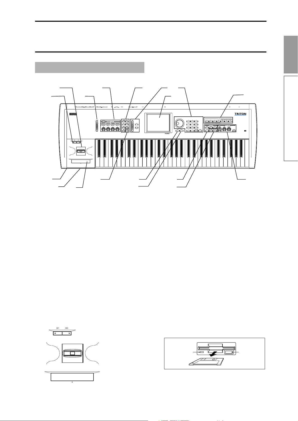
Front panel
☞
p.25).
7
9
p.25).
☞
2
1
6
4
5
1. [SW1] key, [SW2] key
These keys are on/off switches for the functions to
which they were assigned in Program, Combination, Sequencer, Song Play, and Sampling modes.
When on, the LED will light (
2. Joystick
This controls pitch or modulation, etc.
Move the joystick up/down or left/right (+Y, –Y,
–X, +X) to control (
Various program parameters and effect parameters will determine what is controlled by the joystick.
3. Ribbon controller
Slide your finger to the left or right on this ribbon
controller to control the pitch or modulation
(
☞p.25).
Various program parameters and effect parameters will determine what is controlled by the ribbon controller.
3
12
13
8
10
11
14
15
4. Headphone jack
A set of headphones (standard stereo phone plug)
can be connected here (
The output from the L/MONO and R OUTPUT
jacks can be monitored in stereo through the headphones.
5. Floppy disk drive
Insert 3.5 inch 2DD (double-side double-density)
or 2HD (double-side high density) floppy disks
here. Edited data can be saved on a floppy disk,
and the factory preset data, SMF data, or multisampling/sampling data etc. can be loaded from a
floppy disk.
For details on handling floppy disks, refer to
“Floppy disk handling” (
Eject button
To remove a floppy disk, first make sure that the
disk access indicator is dark, and then press this
button. If the disk does not eject when you press
this button, do not attempt to remove the disk by
force. Please contact your dealer.
Introduction
17
Front and rear panel
16
☞p.135).
☞p.95).
Disk access
indicator
Eject button
Page 10

6. [VOLUME] slider
This adjusts the volume that is output from the
OUTPUT jacks (L/MONO, R) and the headphone
jack.
7. REALTIME CONTROLS
Use the [REALTIME CONTROLS] key to select A
or B mode for the realtime controllers, and use
knobs [1]–[4] to control the tone, effects, and MIDI
control changes etc. in realtime (
☞p.26).
[REALTIME CONTROLS] key
This key selects either A or B mode for the realtime
controllers. The selected mode will light.
[1] knob, [2] knob, [3] knob, [4] knob
In A mode, the function of each knob is fixed. [1] is
the low pass filter cutoff frequency, [2] is the filter
resonance level or the cutoff frequency of the high
pass filter, [3] is the filter EG intensity, and [4] is
the filter/amp release time.
In B mode, each knob will control the function that
you assigned in Program, Combination,
Sequencer, Song Play, or Sampling modes.
8. Mode keys
Use these keys to enter the desired mode.
When you press a key, the LED will light, and you
will enter the mode whose key you pressed
(
☞p.12).
[S.PLAY] key
In Song Play mode you can playback Standard
MIDI Files from a floppy disk or external SCSI
device (when the separately sold EXB-SCSI option
is installed), and play along with the playback.
[GLOBAL] key
In Global mode you can make settings that affect
the TRITON’s entire system. In this mode you can
also create drum kits and arpeggio user patterns.
[DISK] key
In Disk mode you can save TRITON data on a
floppy disk or external SCSI media (when the separately sold EXB-SCSI option is installed), and
load data from the above-listed media.
9. [COMPARE] key
Use this key when you wish to compare the sound
of the program or combination that you are currently editing with the un-edited sound that was
written into memory. You can also use this key to
make “before and after” comparisons when
recording or editing in Sequencer mode (
10. VALUE controllers
The following VALUE controllers are used to set
the value of the selected parameter (
☞p.13).
☞p.14).
[COMBI] key
In Combination mode you can play or create combinations.
[PROG] key
In Program mode you can play or create programs.
[SEQ] key
Sequencer mode is mainly for recording/playing
songs. (You can create 16-track sequence data.)
Use this mode when you wish to create an original
song from scratch, or to add to sequence data that
was converted from a Standard MIDI File.
[SAMPLING] key
In Sampling mode you can record samples, edit
the waveform of a sample, and create multisamples. Samples and multisamples created in this
mode can be used by the oscillators of a drum kit
or program.
6
[VALUE] slider
Use this to modify the value of a parameter. This
controller is convenient when you wish to make
large changes in the value.
This slider can also be used as a modulation
source.
[ ][ ] keys
These are used to increase or decrease the parameter value in steps of one. It is convenient to use
these to make fine adjustments.
[VALUE] dial
Use this dial to modify the value of the parameter.
Page 11

Numeric keys [0] – [9]
[ENTER] key
[–] key
[./10’s HOLD] key
Use these keys to numerically input a parameter
value. Use numeric keys [0]–[9], the [–] key, and
the [./10’s HOLD] key to enter the value, and
press the [ENTER] key to confirm it. The [./10’s
HOLD] key lets you input a value with a decimal
point. The [–] key inverts the sign (+/–) of the
parameter value. The [./10’s HOLD] key is also
used when you wish to hold the 10’s place while
selecting programs or combinations.
By holding down the [ENTER] key and pressing a
numeric key [0]–[9], you can select up to ten page
menu commands in the current page.
11. LCD screen
The TRITON features a Touch-View system that
uses a touch-panel LCD screen.
By pressing objects that are shown in the LCD
screen, you can select pages, tabs, and parameters,
and set values (
☞p.10).
12. [EXIT] key
When in P (page) 1–9 of each mode, pressing the
[EXIT] key will move to P (page) 0 of that mode.
When a dialog box is open, this key, will cancel the
settings made in the dialog box and close the dialog box (corresponds to the Cancel button). If a
popup menu or page menu is open, pressing
[EXIT] will close the menu.
13. [MENU] key
Use this key to move between pages. When you
press the [MENU] key, a list of the pages in the
mode will appear in the LCD screen. Press the
desired page, and you will move to that page. You
can also move to a page by holding down the
[MENU] key and pressing the corresponding
numeric key [0]–[9] (
☞p.12).
[FF>>] key
In Sequencer mode this key fast-forwards the song
or cue list playback. When you press and hold this
key, the LED will light, and the playback will fastforward. (This will not function during recording.)
[LOCATE] key
In Sequencer mode, this key returns the song or
cue list playback location to the specified point. In
Song Play mode, this key returns the playback
location of the SMF to the specified point.
If for some reason any “stuck notes” occur, press
this key.
15. SEQUENCER/SAMPLING
[REC/WRITE] key
In Sequencer mode, pressing this key will make
the LED light, and if you then press the [START/
STOP] key, recording will begin (
In Sampling mode, pressing this key will make the
LED light, and if you then press the [START/
STOP] key, sampling will begin (
In Program, Combination and Global modes,
pressing this key will open a dialog box, and if you
then press the OK button, the edited contents will
be written (
☞p.38, p.39).
☞p.64).
☞p.80).
[START/STOP] key
This is the start/stop key for song or cue list
recording and playback in Sequencer mode, and
SMF playback in Song Play mode. (During recording and playback, the LED will blink in time with
the beat.)
In Sampling mode, press the [REC/WRITE] key
(LED lights), and then press the [START/STOP]
key to start/stop sampling. In Sampling P1, pressing this key (the LED will light) will sound the
sample.
Introduction
Front and rear panel
14. SEQUENCER
[PAUSE] key
In Sequencer mode, this key pauses the song or
cue list playback. In Song Play mode, this key
pauses SMF playback. When paused, the LED will
light. Press [PAUSE] once again to defeat pause,
the LED goes off.
[<<REW] key
In Sequencer mode this key rewinds the song or
cue list playback. When you press and hold this
key, the LED will light, and the playback will
rewind. (This will not function during recording.)
16. ARPEGGIATOR
These knobs control the performance of the arpeggiator in realtime (
☞p.29).
[TEMPO] knob
This adjusts the base tempo of the arpeggiator and
sequencer.
[GATE] knob
This adjusts the gate time (note duration) of the
arpeggio notes. At the center position (12 o’clock),
the gate time will be the same as the “Gate”
parameter of the arpeggiator. Rotating the knob
toward the left will shorten the gate time, and
rotating it toward the right will lengthen the gate
time.
7
Page 12
[VELOCITY] knob
This adjusts the velocity (playing strength) of the
arpeggio notes. At the center position (12 o’clock),
the velocity will be the same as the “Velocity”
parameter of the arpeggiator. Rotating the knob
toward the left will weaken the velocity, and rotating it toward the right will strengthen the velocity.
[ON/OFF] switch
This switches the Arpeggiator function on/off.
When on, the LED will light.
Rear panel
1. AC power supply connector
Connect the included power supply cable here.
After connecting the power supply cable to the
TRITON, connect the other end to an AC outlet
(
☞p.15).
2. [POWER] switch
This switch turns the power on/off (☞p.17).
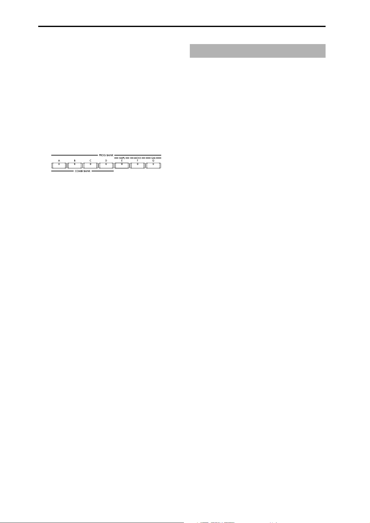
17. [BANK] keys
These keys are used to switch Program/Combination banks.
PROG BANK: [A], [B], [C], [D], [E], [F], [G]
When selecting programs, use keys [A], [B], [C],
[D], [E], [F] (available when the EXB-MOSS is
installed), and [G]. The LED of the selected bank
will light.
Each time you press [G], you will cycle through
the GM(2) variation banks and the drum bank as
follows: G, g(1), g(2), ... g(8), g(9), g(d), G ... etc.
COMBI BANK: [A], [B], [C], [D]
When selecting combinations, use keys [A], [B],
[C], and [D]. The LED of the selected bank will
light.
In Combination, Sequencer, and Song Play modes
when the edit cell (highlighted area) is located at
the program of a timbre or track, you can use the
BANK keys to select the bank of the program. The
bank LED of the program selected for that timbre/
track will light.
3. SCSI connector (separately sold EXB-SCSI
option)
Use a SCSI cable to connect SCSI-compatible
devices (hard disk drives, CD-ROM drives etc.)
here (
☞p.15).
4. TO HOST connector
A special cable (sold separately: AG001B/002B)
can be connected from here directly to your computer, to transmit and receive musical data and
sound settings etc. (
☞p.112).
5. MIDI THRU connector
Musical data and sound settings etc. that are
received at the MIDI IN connector are re-transmitted without change from the MIDI THRU connector.
You can use this to connect multiple MIDI devices
via MIDI cables (
☞p.111).
6. MIDI OUT connector
Musical data and sound settings etc. are transmitted from this connector.
Use this to control another connected MIDI device
from the TRITON (
☞p.111).
7. MIDI IN connector
Musical data and sound settings etc. are received
at this connector.
Use this to play the TRITON from another connected MIDI device (
☞p.111).
8. DAMPER jack
A separately sold switch-type pedal such as the
Korg DS-1H damper pedal can be connected here.
If a DS-1H is connected, it will function as a halfdamper pedal. If another switch-type pedal is connected, it will function as a damper switch. In
order to ensure that the half-damper pedal functions correctly, please adjust the polarity and the
sensitivity (
☞p.115, 121 in the Parameter Guide).
8
Page 13

8
9
10
11
Introduction
1
2
9. ASSIGNABLE SWITCH jack
A separately sold on/off foot switch such as the
Korg PS-1 foot switch can be connected here
(
☞p.16).
Its function can be assigned in Global mode,
allowing you to use the foot switch as a modulation controller, to select programs or combinations,
or to start/stop the sequencer (
10. ASSIGNABLE PEDAL jack
A separately sold Korg EXP-2 or XVP-10 expression pedal can be connected here (
Its function can be assigned in Global mode,
allowing you to use the pedal to control the volume etc. (
☞p.126)
11. [Contrast adjustment] knob
This adjusts the contrast of the LCD screen.
The optimal setting will depend on the height or
angle from which you view the screen display, so
please adjust this as necessary.
12. AUDIO INPUT
These two audio inputs are used when recording a
mono/stereo sample from a mic or external audio
source (
internal effects to an external audio source
(
The MIC/LINE level select switch ([MIC-LINE]
switch) and the level adjustment knob ([LEVEL]
knob) allow you to use a wide range of external
audio sources, from mic level to line level.
☞p.78), or when applying the TRITON’s
☞p.109).
☞p.125).
☞p.16).
3
4
5
6
12
13
7
13. AUDIO OUTPUT
Connect these outputs to the input jacks of your
amp or mixer. In addition to the L/MONO and R
main stereo audio outputs, the TRITON provides
four individual audio outputs. The sound from
each oscillator, drum, timbre/track, or insertion
effect can be freely routed to any output (
(MAIN) L/MONO, R
These are unbalanced phone jacks (☞p.135).
These are the main audio output jacks. By setting
“Bus Select” to L/R, the output from an oscillator,
an insertion effect, an individual drum part, or the
metronome can be output to the (MAIN) L/
MONO and R jacks. When making connections in
stereo, use L/MONO and R. When making connections in mono, use the L/MONO jack.
(INDIVIDUAL) 1, 2, 3, 4
These are unbalanced phone jacks (☞p.135).
These are individual (independent) audio output
jacks. These are individual (independent) audio
output jacks. By several times to make the “Bus
Select” to 1, 2, 3, 4, 1/2, or 3/4, an oscillator, an
insertion effect, an individual drum part, or the
metronome etc. can be assigned to be output from
the (INDIVIDUAL) 1, 2, 3, 4, jacks. The output
from the 1, 2, 3, 4 jacks is not affected by the [VOLUME] slider.
Front and rear panel
☞p.107–).
AUDIO INPUT 1/2 jacks
These are unbalanced phone jacks (☞p.136).
[LEVEL] knob
This adjusts the input level of the AUDIO INPUT
1/2 jacks.
[MIC-LINE] switch
This switches the input level of the AUDIO INPUT
1/2 jacks.
9
Page 14

Names and functions of objects in the LCD
screen
The TRITON’s LCD screen features a Touch View system that uses a touch panel.
By pressing objects displayed in the LCD screen, you
can select pages, set parameter values, rename programs and combinations, write data, and perform
many other operations.
References in the TRITON’s owner’s manual to the
“... button” or “... tab” refer to objects displayed on
the LCD screen. References to the “[...] key,” “[...]
knob,” “[...] dial],” or “[...] slider” refer to controls
on the front or rear panel of the TRITON.
a: Current page
b: Edit cell
d: Popup button (2)
f: Check box
c: Popup button (1)
g: Radio buttons
h: Tab
i: Page menu buttone: (category) Popup button
a: Current page
This shows the page within the currently selected
mode.
From the left, this displays the mode name, the
page number: name selected in the Jump page,
and the tab name.
Mode name Tab namePage number: name
When a popup menu is displayed, operating a
VALUE controller (
☞p.13) will close the popup
menu. If the popup menu is unlocked (see below
“Pin”), it will close if you touch a location outside
the popup menu.
* Popup menu
Pin
Scroll bar
Pin
This switches the popup menu display between
locked and unlocked.
When locked, the pin will be shown closed, and
the popup menu will remain displayed even after
you press a parameter value. When unlocked, the
pin will be shown opened, and the popup menu
will close immediately when you press a parameter value.
Scroll bar
Use this when you wish to see parameter values
that cannot be displayed in the screen at once.
Press here to scroll to left or right.
b: Edit cell
When you press a parameter in the LCD screen,
the parameter or parameter value will sometimes
be highlighted (displayed in inverse video). This is
called the edit cell, and the highlighted item will
be subject to your editing.
The parameter value of the edit cell can be modified using the VALUE controllers (
☞p.13) or by
using a popup button in the LCD screen. For
parameters that accept a key number or a velocity
value, you can also hold down the [ENTER] key
and play a note on the keyboard to enter the key
number or velocity value.
c: Popup button (1)
When this button is pressed, a popup menu will
appear, showing the parameter values that are
available for selection.
To input the parameter value, press the desired
value in the popup menu.
Press here and slide to left
or right to scroll to the
desired location.
Press here to scroll to
the corresponding
location.
d: Popup button (2)
When you press this button, a tabbed popup
menu will appear, allowing you to perform the fol-
lowing selections.
• “Bank/Program Select,” “Bank/Combination
Select”: Select programs or combinations by
bank
• “Multisample Select”: Select a multisample for
a program oscillator by category (ROM
multisamples only)
• “Category/Effect Select”: Select an insert effect
or master effect by category
To close the tabbed popup menu, press the OK
button or Cancel button.
10
Page 15

e: (Category) popup button
When you press this button, a tabbed popup
menu will appear, allowing you to perform the fol-
lowing selections.
• “Category/Program Select,” “Category/
Combination Select”: Select programs or
combinations by category
To close the tabbed popup menu, press the OK
button or Cancel button.
f: Check box
Each time you press a check box, a check mark will
be added or removed.
When checked, the parameter will function; when
unchecked, the parameter will not function.
g: Radio buttons
Press a radio button to select one value from two
or more choices.
After some commands are executed, the previously-locked page menu will be unlocked automatically, and the page menu will be closed.
* Text edit button
When you press this button, a text edit dialog box
will appear.
Here you can rename text (such as the name of a
program, combination, or song etc.) (
☞p.38).
* Page jump menu
Introduction
LCD screen
h: Tab
Press the tab to select a page.
i: Page menu button
When this button is pressed, a list of page menu
commands will appear.
The page menu commands that appear will
depend on the page that is selected.
You can also select up to ten page menu commands by holding down the [ENTER] key and
pressing a numeric key [0]–[9].
The page menu will close when you press the LCD
screen at a location other than the page menu, or
when you press the [EXIT] key.
* Dialog box
The dialog box that appears will depend on the
page menu command that you select.
When selecting a program or combination number
in a dialog box, use the VALUE controllers (
to input the number.
Sometimes a text edit button will be displayed. In
any case, perform the operations directed by the
message in the dialog box.
To execute, press the OK button. To cancel without
executing, press the Cancel button. (The operation
will occur when you press and release the button.)
The dialog box will close. The [EXIT] key corresponds to the Cancel button, Done button, and
Exit button.
☞p.13)
Names and functions of objects in the
In Combination, Program, Sequencer, Sampling,
Song Play, or Global modes, you can press the
front panel [MENU] key to view a list of the pages
in that mode. (As a reminder, the page in which
you were when you pressed the [MENU] key will
have its top right corner bent over.) By pressing
one of the pages shown, you can move to that
page. (You can also move to the corresponding
page by pressing a numeric key [0]–[9].)
When you press the [EXIT] key, P0 will be displayed.
* Other objects
To modify the parameter value of an object shaped
like a slider or knob, press it to move the edit cell
to that object, and use the VALUE controllers to
modify the value. In addition, there are also buttons similar to the OK button and Cancel button
explained in “* dialog box” which execute an operation when they are pressed and released, such as
the Done button, Copy button, and Insert button.
Toggle buttons
This type of button will change its function or
switch on/off each time it is pressed.
PLAY/MUTE/REC button in
Sequencer and Song Play mode
SOLO ON/OFF button in Sequencer
and Song Play mode
Text edit button
Cancel button
ON/OFF button for Insert Effect and
Master Effect
OK button
11
Page 16

Basic operation of the TRITON
1. Selecting modes
● In order to use a particular function on the TRI-
TON, you must first select the appropriate mode.
Press one of the front panel mode keys ([COMBI]
key – [DISK] key) to enter the corresponding
mode.
[COMBI] key: Combination mode
[PROG] key: Program mode
[SEQ] key: Sequencer mode
[SAMPLING] key: Sampling mode
[S.PLAY] key: Song Play mode
[GLOBAL] key: Global mode
[DISK] key: Disk mode
2. Selecting pages and tabs
Each mode has a large number of parameters, which
are grouped into pages. Each page is further divided
into as many as eight groups. These are referred to as
“tabs.”
In Disk mode there is only one page, so the page
jump menu will not appear.
3 In the LCD screen, press the desired page.
You will jump to the selected page, and it will
appear. As an example here, press P1: Edit-Basic.
• As a reminder, the page in which you were when
you pressed the [MENU] key will have its top right
corner bent over.
• You can also jump to the corresponding page by
pressing a numeric key [0]–[9]. (P0–P9 correspond
to numeric keys [0]–[9].)
• By holding down the [MENU] key and pressing a
numeric key [0]–[9], you can jump directly to the
corresponding page without displaying the page
jump menu.
Selecting a page
1 Make sure that the desired mode is selected.
To select a mode, press the appropriate mode key
([COMBI] key – [DISK] key). Here we will use Program mode as an example for our explanation.
Press the [PROG] key.
2 Press the [MENU] key.
The page jump menu will appear.
12
When you press the [EXIT] key, you will return to
P0 from any page.
Selecting a tab
4 Press one of the tabs located at the bottom of the
page.
As an example here, press the “OSC Basic” tab
which is the second from the left.
Page 17

• Some pages have no tabs.
Program and Combination mode P0: Play, the [./10’s
HOLD] key performs the 10’s Hold function. (
☞p.21,
p.23)
5 To move to another page or tab, press the [MENU]
key and repeat the procedure from step 2.
3. Setting a parameter
The parameter value in the edit cell can be set by using
the front panel VALUE controllers ([VALUE] slider,
[ ][ ] keys, [VALUE] dial, numeric keys [0]–[9], [–]
key, [ENTER] key, and [./10’s HOLD] key). As necessary, you can also use the [BANK] keys and the [COMPARE] key.
For some parameters, the value can be set by pressing
a popup button to display the popup menu and then
selecting a parameter value, or by holding down the
[ENTER] key and playing a note on the keyboard to
input a note number or velocity value.
VALUE controllers
[VALUE] slider
Use this when you wish to make major changes in the
value.
In Program mode and Combination mode, this slider
can also be used as a control source for alternate modulation or dynamic modulation. (This is active in Program or Combination P0: Play when the “Program
Number: name” or “Combination Number: name” (the
large characters in the upper part of the LCD) is
selected).
[ ][ ] keys
Use these when you wish to make small changes in the
value.
[VALUE] dial
Use this when you wish to make large changes in a
value.
Numeric keys [0]–[9], [ENTER] key, [–] key,
[./10’s HOLD] key
Use these when you know the parameter value that
you wish to input.
After using the numeric keys [0]–[9] to input a number,
press the [ENTER] key to finalize the parameter value.
Use the [–] key to enter negative numbers.
Use the [./10’s HOLD] key to enter a decimal point. In
[BANK] keys
The [BANK] keys are used in Program mode to select
the program bank and in Combination mode to select
the combination bank. In Combination mode, they are
also used to select the program bank for each timbre of
the combination. In Sequencer and Song Play modes,
these keys are used to select the bank of the program
used by each track of the song.
[BANK] key Program Combination
*1
A
B
C
D
E
F
G
*1
Banks A–D are rewritable user program/combination banks. The factory settings and the preset programs/combinations of the separately sold EXBPCM series options are provided for banks A–D.
*2
Bank E is also a rewritable user program bank (like
banks A–D). We recommend that you use bank E for
programs that you yourself create. When converting
a multisample created in Sampling mode into a program (“Convert MS to Program”), it is best to use
bank E.
*3
Bank F is available if the separately sold EXB-MOSS
option is installed. This bank is only for programs
that use the EXB-MOSS.
*4
Banks G, g(1)–g(9), and g(d) comprise eleven banks.
They contain 256 programs compatible with GM2,
and 9 drum programs. These banks cannot be
rewritten.
Each time you press the BANK [G] key, you will
cycle through banks G, g(1)–g(9), g(d) and back to
G.
Bank G contains 128 programs for the basic GM
sounds. Banks g(1)–g(9) contain variation sounds.
Bank g(d) contains drum programs. In banks which
contain no variation sounds, the basic GM sounds
will be selected. (An asterisk * will be added to the
beginning of the program name.)
Bank A (000...127) Bank A (000...127)
*1
Bank B (000...127) Bank B (000...127)
*1
Bank C (000...127) Bank C (000...127)
*1
Bank D (000...127) Bank D (000...127)
*2
Bank E (000...127) ---
*3
Bank F (000...127) ---
*4
Bank G (001...128) ---
Bank g(1) (001...128) ---
Bank g(2) (001...128) ---
:
Bank g(9) (001...128) ---
Bank g(d) (001...128) ---
Introduction
Basic operation of the TRITON
13
Page 18

G001 Acoustic Piano
g(1) 001 Acoustic Piano w
g(2) 001 Acoustic Piano d
g(3) 001 *Acoustic Piano
g(4) 001 *Acoustic Piano
:
g(9) 001 *Acoustic Piano
g(d) 001 STANDARD Kit
G001 Acoustic Piano
:
[COMPARE] key
Use this key when you wish to compare an edited program or combination sound with the un-edited origi-
nal (i.e., the sound that is written into memory).
When editing a program or combination, press this
key. The LED will light, and the last-written settings
for that program number or combination number will
be recalled. When you press the [COMPARE] key once
again, the LED will go dark and you will return to the
settings that you were editing.
If you edit the settings that are recalled by pressing the
[COMPARE] key (i.e., the settings that are written into
memory), the LED will go dark, and it will not be possible to return to the previous settings by pressing the
[COMPARE] key again.
Popup buttons and popup menus
You can press a popup button to access a popup menu,
and then set parameter values (
☞p.10).
Keyboard input
When inputting a note name or velocity value as the
value of a parameter, you can use the keyboard to
input the setting. Hold down the [ENTER] key and
play the note that you wish to enter as a value. The
note name (number) or velocity value will be input.
When the Global P5: DrumKit page is displayed, you
can hold down the [ENTER] key and play a note to
recall the settings that have been assigned to the note
you played.
In Sampling mode, you can hold down the [ENTER]
key and play a note to recall the index that is assigned
to the note you played.
In Sequencer mode, you can use the [COMPARE] key
to make “before and after” comparisons immediately
after using realtime recording or step recording to
record a song, or after performing a track edit operation.
For example, this can be used effectively when realtime-recording a track for a song.
1 Realtime-record a track. (Take 1)
2 Once again, realtime-record on the same track.
(Take 2)
3 Press the [COMPARE] key. The LED will light,
and take 1 will be recalled.
4 Press the [COMPARE] key once again. The LED
will go dark, and take 2 will be recalled.
5 If at step 3 you once again realtime-record on the
same track (take 3), the object of the Compare
function will now be take 1. If at step 4 you once
again realtime-record on the same track (take 3),
the object of the Compare function will be take 2.
In this way, the Compare function lets you recall the
previous recording or the previous state of event editing.
The Compare function is not available Sampling,
Song Play, or Global modes.
14
Page 19

Connections
Connections must be made with the power turned
off. Please be aware that careless operation may
damage your speaker system or cause malfunctions.
1. Connecting the power cable
● Connect the included power cable to the AC power
supply inlet of the TRITON, and then connect the
other end of the cable to an AC outlet.
2. Connecting audio output
devices
Connect a set of amplified monitor speakers or your
audio system to output the TRITON’s sound.
If you playback the TRITON through your stereo
audio system, be aware that high volumes may
damage your speakers. Be careful not to raise the
volume excessively.
1
to an AC outlet
Power cable (included)
AC power supply inlet
Power switch
7
● Connect the AUDIO OUTPUT (MAIN) L/MONO
and R jacks to the INPUT jacks of your powered
monitor system, etc.
L/MONO and R are the main outputs. If you are
outputting in stereo, make connections to the
(MAIN) L/MONO jack and the R jack. If you are
outputting in monaural, make connections to the
(MAIN) L/MONO jack. We recommend that you
playback in stereo if possible.
● If you wish to output from the AUDIO OUTPUT
(INDIVIDUAL) 1, 2, 3, 4 jacks, connect these jacks
to your mixer, and then connect the mixer output
to the INPUT of your powered monitor system etc.
For details on the output of each jack (
☞p.107–
“Routing”).
3. Connecting audio input
devices
When sampling in Sampling mode, or when you wish
to apply the TRITON’s effects to an external audio
source in Program, Combination, Sequencer, or Song
Headphones
PHONES
Introduction
Connections
CD player, analog record
player, etc.
If you connect a guitar with passive
pickups (i.e., a guitar which does
not contain a preamp), it will not be
possible to sample at an
appropriate level due to the
impedance mismatch. Please route
the guitar signal through a preamp
or an effect processor.
Effect processor etc.
3
2456
Headphones
INPUT
MIC1
BAL
OR
UNBAL
LINE IN 2
LINE IN 1
LOW CUT
75Hz
18dB/OCT
B
d
V
0
1
-
G
A
I
C
N
I
M
U
U
10
60
+10dB
-40dB
TRIM
U
AUX
1
MON/
EFX
+15
U
2
EFX
+15
U
EQ
HI
12kHz
-15
+15
-15
U
GuitarMic
OUTPUT
MID
2.5kHz
-12
-12
+12
U
LOW
80Hz
+15
-15
-15
PAN
L
R
1
MUTE
MUTE
ALT 3–4
ALT 3–4
dB
dB
10
10
SOLO
5
5
U
U
5
5
10
10
20
20
30
30
40
40
50
50
60
60
STEREO AUX RETURNS
MIC4
MIC6
MIC3
MIC5
MIC2
BAL
OR
UNBAL
LOW CUT
75Hz
18dB/OCT
B
d
V
0
1
-
G
A
I
C
N
I
M
10
60
+10dB
-40dB
TRIM
U
AUX
1
MON/
EFX
+15
U
2
EFX
+15
U
EQ
HI
12kHz
+15
U
MID
2.5kHz
+12
U
LOW
80Hz
+15
PAN
L
R
2
SOLO
1
2
LEFT(1/MONO)
RIGHT
BAL
BAL
BAL
BAL
MONO
OR
OR
OR
OR
UNBAL
UNBAL
UNBAL
UNBAL
L
LINE IN 4
LINE IN 6
LINE IN 3
LINE IN 5
BAL
LOW CUT
OR
LOW CUT
LOW CUT
LOW CUT
75Hz
75Hz
75Hz
75Hz
UNBAL
18dB/OCT
18dB/OCT
18dB/OCT
18dB/OCT
B
d
V
0
B
B
B
d
d
d
V
V
V
0
1
0
0
1
-
1
1
-
-
-
R
G
A
G
A
G
G
A
A
I
C
N
I
I
C
I
I
C
C
N
N
N
I
I
I
M
M
M
M
U
U
U
U
LEVEL
+4
10
60
10
10
10
60
60
60
-10
+10dB
-40dB
+10dB
+10dB
+10dB
-40dB
-40dB
-40dB
TRIM
LINE IN 7-8
TRIM
TRIM
TRIM
U
U
U
U
U
AUX
AUX
AUX
AUX
AUX
1
1
1
1
1
MON/
MON/
MON/
MON/
MON/
EFX
EFX
EFX
EFX
EFX
+15
+15
+15
+15
+15
U
U
U
U
U
2
2
2
2
2
EFX
EFX
EFX
EFX
EFX
+15
+15
+15
+15
+15
U
U
U
U
U
EQ
EQ
EQ
EQ
EQ
HI
HI
HI
HI
HI
12kHz
12kHz
12kHz
12kHz
12kHz
-15
+15
-15
-15
+15
+15
-15
+15
-15
+15
U
U
U
U
U
MID
MID
MID
MID
MID
2.5kHz
2.5kHz
2.5kHz
2.5kHz
2.5kHz
-12
+12
-12
-12
-12
+12
+12
+12
-12
+12
U
U
U
U
U
LOW
LOW
LOW
LOW
LOW
80Hz
80Hz
80Hz
80Hz
80Hz
+15
-15
+15
+15
+15
-15
-15
-15
+15
-15
PAN
PAN
PAN
PAN
PAN
L
R
L
L
L
R
R
R
L
R
6
7–8
4
5
3
MUTE
MUTE
MUTE
MUTE
MUTE
ALT 3–4
ALT 3–4
ALT 3–4
ALT 3–4
ALT 3–4
dB
dB
dB
dB
dB
10
10
10
10
10
SOLO
SOLO
SOLO
SOLO
SOLO
5
5
5
5
5
U
U
U
U
U
5
5
5
5
5
10
10
10
10
10
20
20
20
20
20
30
30
30
30
30
40
40
40
40
40
50
50
50
50
50
60
60
60
60
60
PHONES
MAIN OUTS
TAPE
TAPE
AUX SEND
OUTPUT
L
INPUT
1
MICRO SERIES 1402-VLZ
L
14-CHANNEL MIC/LINE MIXER
2
R
R
BAL/UNBAL
ALL BAL/UNBAL
MONO
MONO
MONO
L
L
L
BAL
BAL
BAL
OR
OR
OR
UNBAL
UNBAL
UNBAL
R
R
R
LEVEL
LEVEL
LEVEL
+4
+4
+4
PHONES
-10
-10
-10
LINE IN 13-14
LINE IN 9-10
LINE IN 11-12
U
U
U
U
U
AUX
AUX
AUX
1
1
1
MON/
MON/
MON/
EFX
EFX
EFX
1
+20
+10
+15
+15
+15
NORMALLED
U
+15
U
-15
+15
U
-12
+12
U
+15
-15
L
R
9–10
MUTE
ALT 3–4
dB
10
5
U
5
10
20
30
40
50
60
U
U
U
AUX 1 MASTER
2
PRE
2
2
2
POST
EFX
EFX
EFX
AUX
EFX TO
AUX 1
+20
MONITOR
+15
SELECT
+15
RETURNS
U
U
SOURCE
EQ
EQ
EQ
LEFT RIGHT
HI
HI
HI
MAIN
12kHz
MID
2.5kHz
LOW
80Hz
PAN
SOLO
CLIP+28
12kHz
12kHz
MIX
+10
-15
+15
-15
+15
+7
U
U
ALT
+4
3-4
MID
MID
2.5kHz
2.5kHz
+2
-12
-12
+12
+12
0
TAPE
U
U
-2
LOW
LOW
80Hz
80Hz
-4
+15
+15
-15
-15
-7
ASSIGN
PAN
PAN
-10
TO MAIN MIX
-20
NORMAL(AFL)
-30
LEVEL SET(PFL)
L
L
R
R
SOLO
0dB=0dBu
MODE
13–14
11–12
MUTE
MUTE
POWER
RUDE SOLO LIGHT
PHANTOM
ALT 3–4
ALT 3–4
CONTROL
/ PHONES
MAIN MIX
ROOM
dB
dB
dB
dB
10
10
10
10
SOLO
SOLO
5
5
5
5
U
U
U
U
5
5
5
5
10
10
10
10
20
20
20
20
30
30
30
30
40
40
40
40
50
50
50
50
60
60
60
60
INPUT
Powered monitors, etc.
15
Page 20

Play mode and output the sound from the OUTPUT
jacks, connect a mic or an external audio source to the
AUDIO INPUT 1 and 2 jacks.
● For details on connections when sampling in Sam-
pling mode (
● For details on connections when outputting from
the OUTPUT jacks in other modes (
☞p.78).
☞p.109).
4. Connecting pedals etc.
6. Connections to a computer
An IBM PC (compatible) or Apple Macintosh computer can be connected to the TRITON, so that the TRITON’s keyboard, controllers and sequencer can
transmit data to the computer, and so that the computer can play the TRITON’s tone generator.
● Connect the TRITON’s TO HOST connector to the
appropriate port of your computer (
☞p.112).
Foot pedal connections
A foot pedal controls etc.
Connect a separately sold Korg assignable pedal such
as the XVP-10 or EXP-2 to the rear panel ASSIGN-
ABLE PEDAL jack.
The function controlled by the foot pedal is specified in
Global: P2 “Foot Pedal Assign” (
in the Parameter Guide)
☞p.125). (☞p121, 220
Foot switch connections
A foot switch controls sostenuto, soft pedal on/off,
arpeggiator on/off, to select programs or combinations, and to start/stop the sequencer etc.
Connect a separately sold Korg foot switch such as the
PS-1 to the rear panel ASSIGNABLE SWITCH jack.
The function that will be controlled by the foot switch
and the polarity of the foot switch can be set in Global:
P2 “Foot Switch Assign,” and “Foot Switch Polarity”
(
☞p.125). (☞p.121, 219 in the Parameter Guide)
Damper pedal connections
A damper pedal applies a damper effect as you play.
Connect a separately sold Korg DS-1H damper pedal
to the DAMPER jack of the TRITON. If a DS-1H is connected, half-damper effects can be produced.
The polarity of the pedal is set in Global P1 “Damper
Pedal Polarity” and the sensitivity is set in Global P1
“Half Damper Calibration.” (
ter Guide)
☞p.115, 121 in the Parame-
7. Connections to a SCSI device
If the separately sold EXB-SCSI option is installed, you
can connect the TRITON to a SCSI-compatible device
(hard disk drive, CD-ROM drive, etc.).
For the EXB-SCSI installation refer to p.237 in the
Parameter Guide.
5. Connections to MIDI equipment
The keyboard, controllers and sequencer of the TRITON control and play an external MIDI tone generator,
and an external MIDI keyboard or sequencer plays the
TRITON’s tone generator.
● Use MIDI cables to connect the MIDI connectors
of the TRITON to the MIDI connectors of your
external MIDI device (
16
☞p.111).
Page 21
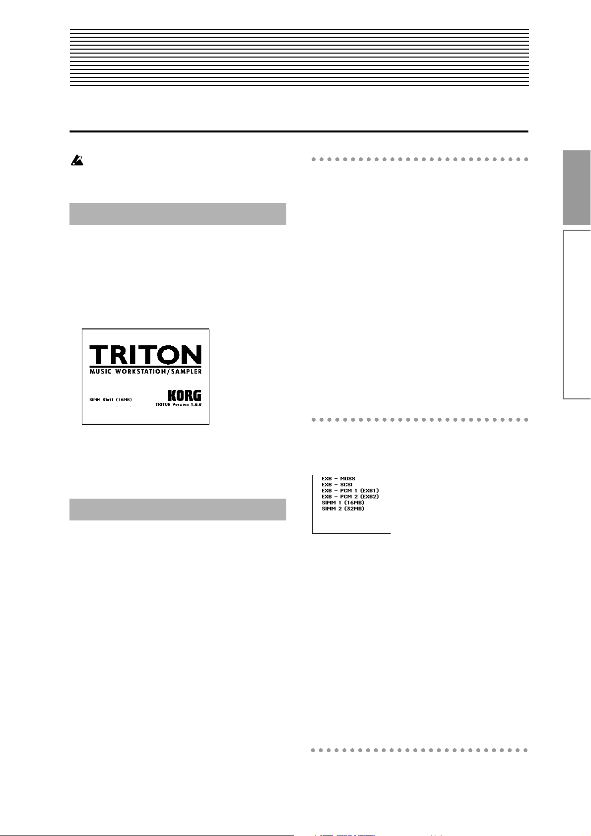
Quick Start
Turning the power on/off
Before you turn on the power, make sure that the
desired connections have been made as described
in “Connections” (
1. Turning the power on
☞p.15).
The mode and page that will be selected when the
power is turned on
The state of the TRITON when the power is turned on
will depend on the setting of “Power On Mode” (Global P0: System Preference tab).
Quick Start
1 Press the TRITON’s [POWER] switch to turn on
the power.
The LCD screen will display the name of your
model (TRITON, TRITON pro, or TRITON proX),
and the software version.
(The following graphic shows the factory-set LCD
screen of the TRITON. The version number is subject to change without notice.)
2 Turn on your powered monitors or stereo amp.
3 Raise the TRITON’s [VOLUME] slider to an
appropriate level, and adjust the volume of your
powered monitors or stereo amp.
2. Turning the power off
1 Set the TRITON’s [VOLUME] slider and the vol-
ume of your powered monitor or stereo amp to
zero.
2 Turn off the power of your powered monitor or
stereo amp.
3 Press the TRITON’s [POWER] switch to turn off
the power.
If “Power On Mode” is Reset (factory setting), the TRITON will automatically selects the Combination mode
P0: Play.
If “Power On Mode” is Memorize, the TRITON will be
in the mode and page that were last selected when the
power was turned off.
The Memorize setting will remember the mode and
page that were last selected, the combination number
that was last selected in Combination mode, and the
program number that was last selected in Program
mode.
If another mode is selected when the power is turned
on, you can press the [COMBI] key or [PROG] key to
select the P0: Play page with the last-selected combination number or program number.
The LCD screen when separately sold options or
SIMM modules are installed
The TRITON series allows you to install separately
sold options or SIMM (sampling memory) boards.
When the power is turned on, the
type of installed options will be
displayed. After installing an
option, be sure to check this display to verify that the option was
installed correctly. If the option is
not displayed here even though it was installed, it was
not installed correctly. Turn off the power and re-install
the option. (
to p.237 in the Parameter Guide)
EXB-MOSS: The EXB-MOSS option is installed.
EXB-SCSI: The EXB-SCSI option is installed.
EXB-PCM Slot1 (
installed in EXB-PCM series slot 1. The type of board is
shown in parentheses.
EXB-PCM Slot2 (
installed in EXB-PCM series slot 2. The type of board is
shown in parentheses.
SIMM Slot1 (**MB): A SIMM is installed in SIMM slot
1. The capacity of the SIMM is shown in parentheses.
When the TRITON is shipped from the factory, a 16 MB
SIMM is already installed in this slot.
SIMM Slot2 (**MB): A SIMM is installed in SIMM slot
2. The capacity of the SIMM is shown in parentheses.
☞For details on installing an option, refer
): A PCM expansion board is
****
): A PCM expansion board is
****
Turning the power on/off
17
Page 22

Listening to a demo song
Here’s how to listen to a demo song on the TRITON.
Contents of the disks
The TRITON series comes with two floppy disks
(TNFD-00P and TNFD-01P).
PRELOAD.PCG
• Preloaded data (programs, combinations, drum
kits, arpeggio patterns, global settings)
• Program data (programs using the sampling
function) used by the demonstration songs
When you load PRELOAD.PCG, it will be written
into internal memory. This data is preserved even
if the power is turned off.
When you load PRELOAD.PCG, the data that had
been written before loading this data will be
rewritten. If you wish to keep this data, you must
first save it on a floppy disk before loading PRELOAD.PCG (
PRELOAD.SNG
• Demonstration song and demonstration cue list
data
When you load PRELOAD.SNG, it will be written
into internal sequencer memory. This memory is
volatile, and the data will be lost when the power
is turned off.
☞p.40).
1. Loading the demo song data
in Disk mode
1 Insert the included “TNFD-00P” floppy disk into
the disk drive.
For details on handling a floppy disk and inserting
it into the disk drive, refer to “Disk mode”
2 Press the [DISK] key (the LED will
light).
You will enter Disk mode.
3 Press the Load tab.
The Load window will appear, and file information
will be displayed.
4 Press “PRELOAD.SNG.”
The display will be highlighted. This is the demo
song data.
4
☞p.95.
5
When you load PRELOAD.SNG, the data that had
been written before loading this data will be
rewritten. If you wish to keep this data, you must
first save it on a floppy disk before loading PRELOAD.SNG. (
PRELOAD.KSC
• Sample program data used by the demonstration
songs
When you load PRELOAD.KSC, its multisample/
sample data will be written into the TRITON’s
multisample/sample memory. This memory is
volatile, and the data will be lost when the power
is turned off.
Whether or not previously-written data will be
erased when you load PRELOAD.KSC is determined by the “Select .KSC Allocation” setting.
Refer to step 7 of the following procedure.
☞p.40)
3
5 Press the page menu command button.
The page menu commands will be displayed.
6 Press “Load selected.”
A dialog box will appear.
7 Press the check boxes to add a check mark.
Check “Load PRELOAD.PCG too.” When the data
is loaded, the .PCG file will be loaded along with
the .SNG file.
Check “Load PRELOAD.KSC too.” When the data
is loaded, the .KSC file will be loaded along with the
.SNG file.
18
Page 23
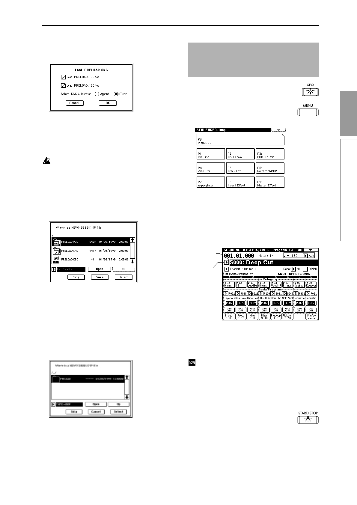
The “Select .KSC Allocation” radio buttons specify
how the sample data will be loaded into sample
memory. For this example, select Clear.
2. Selecting and playing a demonstration song in Sequencer
mode
B Press the [SEQ] key (the LED will light).
You will enter Sequencer mode.
C Press the [MENU] key.
If you load with “Select .KSC Allocation” set to
Clear, the sample data will be loaded from the
beginning of the sample memory area.
If you load with “Select .KSC Allocation” set to
Append, the sample data will be loaded into the
unused portion of the sample memory.
If sample memory already contains sample data
that you do not wish to lose, either select Append,
or save the sample data to a floppy disk (
8 Press the OK button.
The data will be loaded in the order of PRELOAD.PCG, PRELOAD.SNG, and PRELOAD.KSC.
When the PRELOAD.KSC file begins to load, the
following dialog box will appear.
☞p.40).
The LCD screen will show a list of the
pages in Sequencer mode.
Quick Start
For this example, press either “P0: Play/REC” or
numeric key [0]. The P0: Play/REC page will
appear.
Listening to a demo song
D Select the demonstration song.
Press the “Song No. and name” area to highlight the
song name.
Song No. and
name
Popup button
The sample/multisample data listed in PRELOAD.KSC is contained in “TNFD-01P.”
9 Remove the “TNFD-00P” floppy disk from the
floppy disk drive, and insert the “TNFD-01P”
floppy disk.
0 Press the LCD screen once.
The LCD display will change. (The newly inserted
floppy disk will be recognized when you press the
LCD screen.)
A Press the Select button to resume loading.
E To select the first song, press numeric key [0], and
press the [ENTER] key.
To select the second song, press numeric key [1],
and press the [ENTER] key.
You can select songs from a popup menu.
Press the popup button for “Song No. and name”
to access the popup menu.
In the LCD screen, press the song that you wish to
play. The popup menu will close, and the song you
pressed will be selected.
F Press the front panel [START/STOP] key.
The LED will blink and the selected song will play.
G If you wish to stop playback, press the [START/
STOP] key once again.
19
Page 24

3. Playing a cue list
Here’s how to playback the demonstration cue list. A
cue list allows you to playback multiple songs in succession, and specify the number of times that each
song will be repeated.
1 Press the [MENU] key.
The LCD screen will show a list of the pages in
Sequencer mode.
2 Press either “P1: Cue List” or numeric key [1].
The P1: Cue List page will appear.
3 Press the [START/STOP] key.
4 To stop playback, press the [START/STOP] key
once again.
If the last step is End, playback will stop automatically when it reaches that point. If the last step is
Continue to Step01, playback will return to the first
step and continue.
Cue lists can be selected in the same way that
songs are selected. Refer to E and F in the previous page.
20
Page 25

Selecting and playing a program
In Program mode you can select a program from
banks A–G and play it. Here we will show how to
select preset programs. Select various programs and
hear how they sound.
Selecting a program
1 Press the [PROG] key (the LED will light), and you
will enter Program mode.
2 Make sure that P (page) 0: Play is selected in the
LCD screen.
If this page is not selected, press the [MENU] key to
access the page jump menu, and either select “P0:
Play” in the LCD screen or numeric key [0] to display P0: Play.
Category
popup
button
Program
Number:
name
Popup button
make a selection.
If you press the [./10’s HOLD] key to turn on the
10’s Hold function (the LCD screen will indicate
), the ten’s place of the program number will be
fixed, and you will be able to switch programs simply by pressing a single numeric key. Each time you
press a numeric key, the one’s place will change.
You can also use the [ ][ ] keys to change the
ten’s place.
To release the 10’s Hold function, press the [./10’s
HOLD] key once again.
Selecting programs from Bank/Program Select
You can select programs from a list organized by program bank.
1 Press the “Program Number: name” popup button.
A tabbed “Bank/Program Select” popup menu will
appear.
Quick Start
Selecting and playing a program
3 Press “Program Number: name” in the LCD screen
to select the program.
The display will be highlighted.
4 Press a PROGRAM BANK [A]–[G] key to select
the bank. (
TON”)
For example to select bank A, press the [A] key.
(The LED will light, and the upper left of the LCD
screen will indicate Bank A.)
Bank G is unlike other banks. Each time you press
the [G] key, the selection will cycle in the order of G
→ g(1) → g(2) → g(3) → g(4) → g(5) → g(6) → g(7)
→ g(8) → g(9) → g(d) → G (the LED will light, and
the upper left of the LCD screen will indicate Bank
G, g(1)–g(9), g(d) respectively.
5 Use numeric keys [0]–[9] to input the program
number, and press the [ENTER] key. Alternatively,
you can use the [VALUE] dial or [][] keys to
☞p.22 “Program banks of the TRI-
In the graphic, bank A is selected. The center area
shows the programs contained in that bank.
2 Press the tabs located at the left and right to select
banks.
3 Press program names in the center area to select
programs.
The selected program will be highlighted.
4 When you are satisfied with the selected program,
press the OK button to close the popup menu.
If you press the Cancel button, the selection you
made here will be discarded, and you will return to
the program that had been selected when you
opened the popup menu.
21
Page 26

Selecting programs from Category/Program Select
You can select programs from a list organized by category. With the factory settings, the programs are classified into sixteen categories of instrument (keyboard,
organ, bass, drums etc.).
1 Press the Category popup button.
A tabbed “Category/Program Select” popup menu
will appear.
In the above graphic, category 10: FastSynth is
selected. The center area shows the programs contained in that category.
2 Press the tabs located at the left and right to select
a different category.
The name of the selected category will be displayed
in full in the upper right.
Program banks of the TRITON
The TRITON contains program banks A–G.
• Banks A–E each contain 128 programs (numbered
000–127), for a total of 640 programs.
With the factory settings, banks contain a variety of
preset programs that use the internal PCM ROM
multisamples, effects, and arpeggiator patterns etc.
With the factory settings, bank E does not contain
programs. It can be used as a user bank for you to
write programs you yourself create (such as programs that use multisamples you sampled in Sampling mode).
• Bank F can be used if the EXB-MOSS option (sold
separately) is installed. It can contain 128 programs
(numbered 000–127) that use the MOSS tone
generator. (
owner’s manual of the EXB-MOSS option.)
• Bank G contains 256 programs compatible with
the GM2 sound map, and nine drum programs.
This bank is read-only.
Bank G consists of banks G, g(1), g(2)–g(9), and g(d).
The 128 programs from 001–128 can be used. G con-
tains the GM2 original programs. g(1)–g(9) allow
you to select variation programs of the G bank programs. g(d) lets you select drum programs.
☞ For the preset program banks and program names,
refer to the separate Voice Name List.
☞For the program names, refer to the
3 Press a program name in the center area to select a
program.
The selected program will be highlighted.
If you wish to change a program to a different category, you can set in the dialog box when writing
the program (
changed in “Category Name” (Global P4).
4 When you are satisfied with the selected program,
press the OK button to close the popup menu.
If you press the Cancel button, the selection you
made here will be discarded, and you will return to
the program that had been selected when you
opened the popup menu.
☞p.39). Category names can be
Other ways to select a program
Using a connected switch to select programs
☞p.125)
(
An separately sold on/off type foot switch such as the
Korg PS-1 can be connected to the ASSIGNABLE
SWITCH jack, and used to select programs.
Selecting programs from a MIDI device (☞p.114)
MIDI program change messages can be transmitted
from an external MIDI device, and received by the TRITON to select programs.
22
Page 27
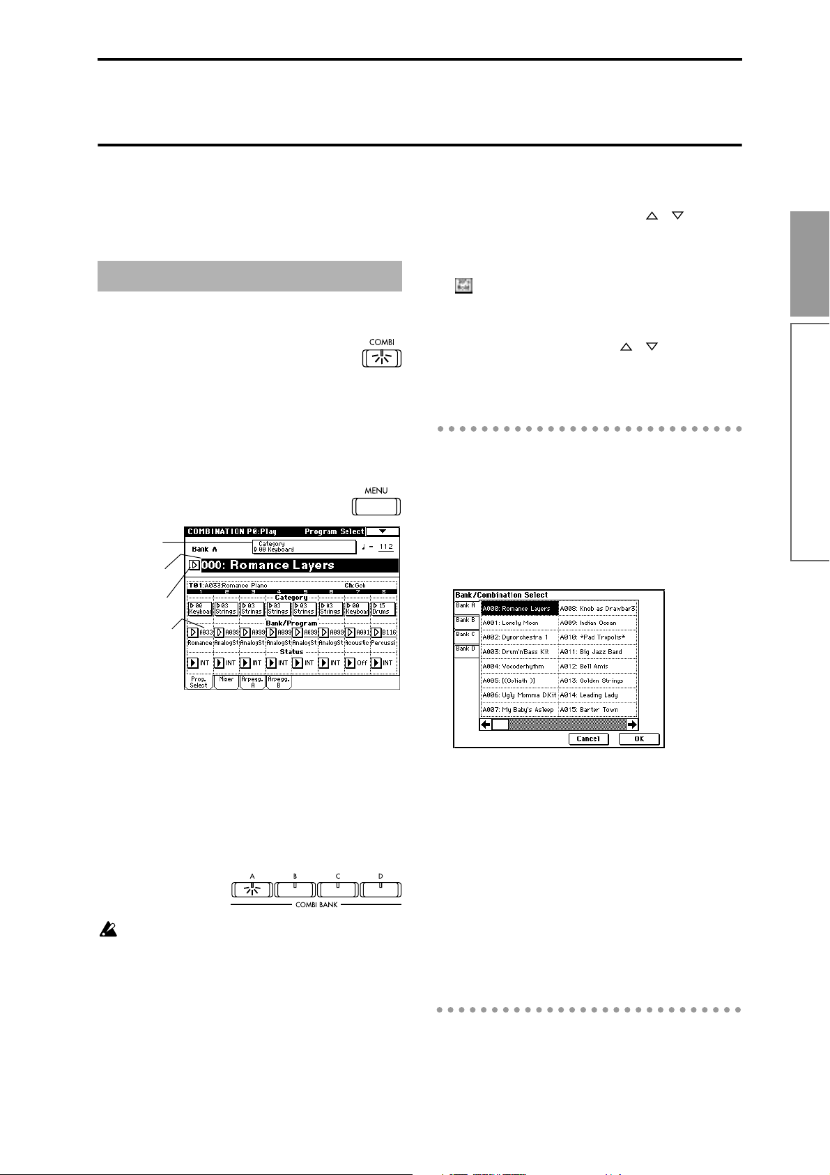
Selecting and playing a combination
In Combination mode you can select a combination
from banks A–D and play it. Here we will show how
to select preset combinations. Select various combinations and hear how they sound.
Selecting a combination
1 Press the [COMBI] key (the LED will light), and
you will enter Combination mode.
2 Make sure that P (page) 0: Play is selected in the
LCD screen.
If this page is not selected, press the [MENU] key to
access the page jump menu, and either press “P0:
Play” in the LCD screen or numeric key [0] to display P0: Play.
Category popup
button
Combination
Number: name
Popup button
5 Use numeric keys [0]–[9] to input the combination
number, and press the [ENTER] key. Alternatively,
you can use the [VALUE] dial or [][] keys to
make a selection.
If you press the [./10’s HOLD] key to turn on the
10’s Hold function (the LCD screen will indicate
), the ten’s place of the combination number will
be fixed, and you will be able to switch combinations simply by pressing a single numeric key. Each
time you press a numeric key, the one’s place will
change. You can also use the [ ][ ] keys to
change the ten’s place.
To defeat the 10’s Hold function, press the [./10’s
HOLD] key once again.
Selecting combinations from Bank/Combination
Select
You can select combinations from a list organized by
combination bank.
1 Press the “Combination Number: name” popup
button.
A tabbed “Bank/Combination Select” popup menu
will appear.
Quick Start
Selecting and playing a combination
Bank/Program
3 Press “Combination Number: name” in the LCD
screen to select the combination.
The display will be highlighted.
4 Press a COMBI BANK [A]–[D] key to select the
bank. (
☞p.24 “Combination banks of the TRI-
TON”)
For example to select bank A, press the [A] key.
(The LED will light, and the upper left of the LCD
screen will indicate Bank A.)
When the edit cell is located at the “Bank/Program” of a timbre 1–8, pressing a [BANK] key will
allow you to select the program bank for that timbre, and the LED of the program bank selected for
that timbre will light. If you wish to select a combination bank, make sure that the edit cell is not
located at the “Bank/Program” of timbres 1–8.
In the above graphic, bank A is selected. The center
area shows the combinations contained in that
bank.
2 Press the tabs located at the left to select banks.
3 Press combination names in the center area to
select combinations.
The selected combination will be highlighted.
4 When you are satisfied with the selected combina-
tion, press the OK button to close the popup menu.
If you press the Cancel button, the selection you
made here will be discarded, and you will return to
the combination that had been selected when you
opened the popup menu.
23
Page 28

Selecting combinations from Category/Combination Select
You can select combinations from a list organized by
category. With the factory settings, the combinations
are classified into sixteen categories of instrument
(keyboard, organ, bass, drums etc.). Here the combinations are divided into sixteen categories.
1 Press the Category popup button.
A tabbed “Category/Combination Select” popup
menu will appear.
In the graphic, category 00: Keyboard is selected.
The central area shows the combinations contained
in that category.
2 Press the tabs located at the left and right to select
a different category.
Other ways to select a combination
Using a connected switch to select combinations
(☞p.125)
An separately sold on/off type foot switch such as the
Korg PS-1 can be connected to the ASSIGNABLE
SWITCH jack, and used to select combinations.
Selecting combinations from a MIDI device
(☞p.114)
MIDI program change messages can be transmitted
from an external MIDI device, and received by the TRITON to select combinations.
Combination banks of the TRITON
The TRITON contains combination banks A–D.
Each bank contains 128 combinations (numbered 000–
127), for a total of 512 combinations.
With the factory settings, these banks contain a variety
of preset combinations that use programs, effects, and
arpeggio patterns.
☞ For the preset combination banks and combination
names, refer to the separate Voice Name List.
The name of the selected category will be displayed
in full in the upper right.
3 Press a combination name in the central area to
select a combination.
The selected combination will be highlighted.
Press the scroll bar to move to additional pages of
combinations in the selected category.
If you wish to change a combination to a different
category, you can set in the dialog box when writing the combination (
be changed in “Category Name” (Global P4).
4 When you are satisfied with the selected combina-
tion, press the OK button to close the popup menu.
If you press the Cancel button, the selection you
made here will be discarded, and you will return to
the combination that had been selected when you
opened the popup menu.
☞p.39). Category names can
24
Page 29

Using controllers to modify the sound
The TRITON provides a variety of controllers that can
be used to control the tone, pitch, volume, effects, and
arpeggiator etc. in realtime while you play.
Joystick
+Y
−X +X
−Y
SW1, SW2
You can use these keys as sources for alternate modulation or effect dynamic modulation to control program
parameters or effect parameters.
These switches can also be used to switch the octave, to
turn portamento on/off, or to lock the position of the
ribbon controller or after touch function.
Quick Start
JS(+X): Move the joystick toward the right to apply an
effect. Normally this is used to control the
pitch (bend up).
JS(–X): Move the joystick toward the left to apply an
effect. Normally this is used to control the
pitch (bend down).
JS(+Y): Move the joystick away from yourself to apply
an effect. Normally this is used to control the
oscillator LFO (vibrato).
JS(–Y): Move the joystick toward yourself to apply an
effect. Normally this is used to control filter
LFO (wah).
You can use the Lock function of SW 1 or 2 to hold
the effect even after the joystick is returned to the
center position. For the procedure, refer to “SW1,
SW2.”
You can use the joystick as a source for alternate
modulation or effect dynamic modulation, to control program parameters or effect parameters.
Ribbon controller
−X +X
Move your finger to the left and right on the ribbon
controller to apply an effect.
Normally, this is used to control pitch, volume or filter
etc.
You can use the Lock function of SW 1 or 2 to hold
the effect even after you release your finger from
the ribbon controller. For the procedure, refer to
“SW1, SW2.”
You can use the ribbon controller as a source for
alternate modulation or effect dynamic modulation, to control program parameters or effect
parameters.
You can specify the way in which the [SW1] and [SW2]
keys will operate: either Toggle, when the assigned
function will be switched on/off each time the key is
pressed, or Momentary, when the assigned function
will be switched on only as long as you hold down the
key.
In Program mode, the function of the [SW1] and
[SW2] keys can be checked in the P0: Play tab Performance (
When you write a program or combination, the
on/off status of the [SW1] and [SW2] keys is
saved.
For details on making these settings, refer to “Setting the functions of [SW1] and [SW2]” (
☞p.27).
☞p.127).
The Lock function
Joystick
When the [SW1] or [SW2] key function is set to JS X
Lock, JS +Y Lock, or JS –Y Lock, the sound produced
by moving the joystick can be held even after the joystick is returned to the center position.
When the [SW1] key is set to JS–Y Lock and is operating as a Toggle switch, the lock function can be used as
described in the following example.
1 Move the joystick toward yourself to modify the
sound.
2 While continuing to hold the joystick toward your-
self, press [SW1] (the [SW1] key LED will light).
The sound at this point will be held.
3 Even if you release the joystick, or move it toward
yourself once again, the sound will remain
unchanged from when the [SW1] key was pressed.
This is the “locked” condition. Moving the joystick
to left or right will produce the normal result.
Using controllers to modify the sound
25
Page 30

4 To release the locked condition, press the [SW1]
key once again.
3 Even when you apply further pressure to the key-
board, the sound at the moment you pressed [SW1]
key will be held.
This is the “locked” condition.
4 To release the locked condition, press the [SW1]
key once again.
Realtime control knobs
Ribbon controller
When the [SW1] or [SW2] key function is set to Ribbon
Lock, the sound produced by moving the ribbon con-
troller can be held even after the ribbon controller is
released.
When the [SW1] key is set to Ribbon Lock and is oper-
ating as a Toggle switch, the lock function can be used
as described in the following example.
1 Press [SW1] (the [SW1] key LED will light).
2 Move your finger to left or right on the ribbon con-
troller. The sound will change.
3 Even when you remove your finger from the rib-
bon controller, the sound at that point will be held.
This is the “locked” condition.
4 To release the locked condition, press the [SW1]
key once again.
[1], [2], [3], [4]
These knobs can be used to control the filter cutoff frequency and resonance, the amp and filter EG, volume,
portamento time, pan, pitch LFO, or the send levels to
the master effects, etc.
1 Press the [REALTIME CONTROLS] key to switch
the function of the realtime controllers to A mode
or B mode.
Each time you press the key, A mode or B mode will
be selected alternately, and the corresponding LED
will light.
The selected mode
will light.
2 Rotate the desired knob to control the sound, etc.
A mode controls
In A mode, knobs [1]–[4] will control/edit the following functions.
Placing the knobs in the center (12 o’clock) position
will produce the values specified by the program
parameters.
When the [SW1] or [SW2] key function is assigned
to JS X & Ribbon Lock, JS+Y & Ribbon Lock, or
JS–Y Ribbon Lock, both locking functions will
apply simultaneously.
After touch
When the [SW1] or [SW2] key function is set to After
Touch Lock, the sound produced by applying pressure
to the keyboard can be held even after the keyboard is
released.
When the [SW1] key is set to After Touch Lock and is
operating as a Toggle switch, the lock function can be
used as described in the following example.
1 After playing a note, apply pressure to the key-
board (after touch). The sound will change.
2 While maintaining the pressure on the keyboard,
press [SW1] (the [SW1] key LED will light).
26
Knob [1]: LPF CUTOFF
Adjust the cutoff frequency of the low pass filter.
When you adjust the cutoff frequency of the filter, the
brightness of the sound will change. The effect will
depend on the settings of the program parameters, but
normally, rotating the knob toward the left will darken
the sound, and rotating it toward the right will
brighten it.
Level
LPF
Frequency
Cutoff
frequency
HighLow
Knob [2]: RESONANCE/HPF
Adjust the resonance level of a low pass filter or the
cutoff frequency of a high pass filter.
The content that is controlled will depend on the filter
type specified by the program.
Page 31

By adjusting the filter resonance level, you can increase
or decrease the resonance level to add a unique character to the sound.
By adjusting the cutoff frequency of a high pass filter,
you can modify the brightness of the sound.
Level
LPF HPF
Cutoff
frequency
Knob [3]: EG-INTENSITY
Adjust the filter EG intensity (the depth at which the
filter EG is applied).
Rotating the knob will affect the depth of the filter EG.
Normally, rotating the knob toward the left will make
the filter EG apply less deeply, and rotating it toward
the right will make the filter EG apply more deeply.
Since the filter EG will operate based on the cutoff frequency of the filter, knobs [1] and [3] will work
together to control the tonal changes produced by the
filter.
Level
B mode controls
You can control parameters such as volume, portamento time, pan or filter and amp EG, pitch LFO, and
master effect send levels etc.
In each preset program, appropriate functions are
assigned to the B-mode knobs. The functions that
are assigned can be viewed in the LCD screen.
The B-mode function settings are made for each individual program, combination, or song. In Sampling
mode and Song Play mode, the B-mode functions are
set for the entire mode.
For details on making these settings (
Viewing the parameters that are assigned to
[SW1], [SW2], and the realtime control B-mode
In Program mode, the P0: Play shows the functions
that are assigned to [SW1] and [SW2], and to the Bmode of realtime control knobs [1], [2], [3], and [4].
Functions
assigned to Bmode knobs
[1]–[4]
Functions
assigned to
[SW1] and
[SW2] keys
☞p.127).
Quick Start
Using controllers to modify the sound
Time
Knob [4]: EG-RELEASE
Adjust the EG release times of the filter and amp. This
will determine the time from note-off until the sound
disappears.
When you operate the knob, the release times of the filter EG and the amp EG will change. Normally, rotating
the knob toward the left will shorten the release time,
and rotating it toward the right will lengthen the
release time.
When the arpeggiator is running, it is effective to use
this in conjunction with the arpeggiator [GATE] knob
to control the arpeggiated notes.
note-on
Level
Attack Level
Decay Time
Attack Time
Start Level
Break Level
Sustain Level
Slope Time
note-off
Release Time
Release Level
Time
[VALUE] slider
When a program number is selected in Program
P0: Play, or when a combination number is
selected in Combination mode page P0: Play,
you can use the [VALUE] slider as a source for
alternate modulation or effect dynamic modulation, and control program parameters or effect
parameters.
Keyboard
Velocity
The force with which you play a note can apply an
effect.
Normally this is used to control volume, or the speed
or sensitivity of the EG.
After Touch
An effect can be applied by pressing down on the keyboard after playing a note.
Normally this is used to control volume, tone (cutoff
frequency), or LFO sensitivity etc.
27
Page 32

Note Number
An effect can be applied by the note number (keyboard
location) that you play.
Normally this is used to control volume, tone (cutoff
frequency), LFO sensitivity, and EG sensitivity etc.
This can be used as a source for alternate modulation or effect dynamic modulation, to control program parameters or effect parameters.
Foot pedals
Damper Pedal
A separately sold Korg switch-type damper pedal such
as the DS-1H can be connected to the TRITON. If a DS1H is connected, it will function as a half-damper
pedal. The half-damper function cannot be controlled
by other pedals.
Assignable Foot Switch
A separately sold on/off switch such as the Korg PS-1
foot switch can be connected to the TRITON, allowing
you to turn an assigned function on/off by stepping on
the foot switch.
The function of the foot switch is assigned in Global
P2: Controller “Foot Switch Assign” (
☞p.125).
Assignable Foot Pedal
A separately sold Korg expression pedal such as the
EXP-2 orXVP-10 can be connected to the ASSIGNABLE
PEDAL jack, and used to apply an effect.
The function of the foot pedal is assigned in Global
mode P2: Controller “Foot Pedal Assign” (
☞p.125).
ARPEGGIATOR [TEMPO] knob,
[GATE] knob, [VELOCITY] knob
These knobs control the effect of the arpeggiator in
realtime. For details on the operation, refer to p.29
“Using the arpeggiator while you play.”
28
Page 33

Using the arpeggiator while you play
The arpeggiator is a function that automatically generates arpeggios (broken chords). Most arpeggiators produce an arpeggio when you play a chord on the
keyboard.
The chord you played on
the keyboard is sounded as
an arpeggio (broken chord)
In addition to this, the TRITON’s arpeggiator is a polyphonic arpeggiator that is able to produce a variety of
chordal transformations or phrases based on the pitch
or timing of the notes you play on the keyboard. These
functions let you use the arpeggiator to play a wide
range of patterns including drum or bass phrases, and
guitar or keyboard backing riffs. It is also effective to
use the arpeggiator as part of the sound-creating process when creating subtly-moving pads, synth-sounds,
or sound effects.
In addition, the TRITON features a Dual Arpeggiator
that lets you simultaneously use two arpeggio patterns
in Combination mode, Sequencer mode, and Song Play
mode. You can take advantage of this in many ways,
such as applying separate arpeggio patterns to a
drums program and a bass program, or using keyboard split or velocity to switch between two arpeggio
patterns.
The TRITON provides five preset arpeggio patterns
(the standard UP, DOWN, ALT1, ALT2, and RAN-
DOM), and lets you program and store 232 user arpeggio patterns. With the factory settings, these contain a
wide variety of preset user patterns. An arpeggio pattern that you create can also be stored as a user arpeggio pattern.
For the arpeggio pattern names, refer to the separate
Voice Name List.
the arpeggiator. Arpeggios will begin sounding
when you play the keyboard.
2 As described in the following sections “Settings
using controllers” and “Settings in the LCD
screen,” move the controllers or modify the parameters to change the way in which the arpeggios are
played.
Settings using controllers
Arpeggiator on/off
● Each time you press the ARPEGGIATOR [ON/
OFF] key, the arpeggiator will be switched on/off.
When the arpeggiator is turned on, the LED will
light, and the selected arpeggio pattern will begin
sounding when you play the keyboard.
The on/off status is saved when you write the program.
In Combination, Song, and Song Play modes,
depending on the arpeggiator A, B settings, the
arpeggio may not start when you press the
ARPEGGIATOR [ON/OFF] key to turn it on
(
☞p.31).
Adjusting the arpeggiator tempo
Rotate the ARPEGGIATOR [TEMPO] knob to adjust
the tempo. The “ =” display in the upper right of the
LCD will change. The tempo can be adjusted over a
range of 40–240. You can also set the tempo by selecting “ =,” using numeric keys [0]–[9] to enter a tempo,
and pressing the [ENTER] key. The tempo can also be
set by the [VALUE] slider, [VALUE] dial, or [ ][ ]
keys. The LED will blink in time with the specified
tempo.
Quick Start
Using the arpeggiator while you play
Using the arpeggiator in Pro-
gram mode
1 Press the [PROG] key to enter Program mode, and
select a program. (
a program”)
As you select various programs, you will notice that
the ARPEGGIATOR [ON/OFF] key LED will light
for some programs. (
tor to programs”) When you press the keyboard, the
arpeggiator will start.
For other programs, you can press the ARPEGGIATOR [ON/OFF] key (the LED will light) to turn on
☞p.21 “Selecting and playing
☞p.31 “Linking the arpeggia-
The knob setting is saved when you write the program.
The arpeggio playback speed is affected by the
“Reso” setting (Program P0: Arpeggio tab, or
“Resolution” P7: Arpeg.Setup tab).
If “MIDI Clock” (Global P1: MIDI) is set to Exter-
nal MIDI or External PCI/F, the display will indicate “ =” EXT. The tempo will be synchronized to
an external MIDI device, and it will not be possible
to adjust the tempo on the TRITON.
29
Page 34

Adjusting the length of the arpeggio notes
Rotate the ARPEGGIATOR [GATE] knob to adjust the
length of the arpeggio notes. Rotating the knob toward
the left will shorten the notes, and rotating it toward
the right will lengthen the notes. At the center position
(12 o’clock), the note length will be as specified by the
program parameter “Gate” (Program P7: Arpeg. Setup
tab).
● Press “Pat” (Pattern Select).
Use the [VALUE] slider, [VALUE] dial, [ ][ ]
keys, or popup menu to select the desired arpeggio
pattern. To select a user arpeggio pattern U000–231,
use numeric keys [0]–[9] to input the pattern number, and press the [ENTER] key (
☞p.96).
Changing the interval of the arpeggio notes
The “Reso” (Resolution) parameter in the LCD screen
lets you set the interval between arpeggio notes in a
range of 3 – .
The knob setting is saved when you write the program.
It is effective to control this in conjunction with the
REALTIME CONTROLS A-mode knob [4] EG
RELEASE.
Adjusting the strength of the arpeggio notes
Rotate the ARPEGGIATOR [VELOCITY] knob to
adjust the strength of the arpeggio notes. Rotating the
knob toward the left will make the notes weaker, and
rotating the knob toward the right will make the notes
stronger. At the center position (12 o’clock), the velocity will be as specified by the program parameter
“Velocity” (Program P7: Arpeg. Setup tab).
The knob setting is saved when you write the program.
It is effective to control this in conjunction with the
REALTIME CONTROLS A-mode knobs [1]–[3]
LPF CUTOFF, RESONANCE/HPF, and EG-
INTENSITY.
Settings in the LCD screen
● In Program P0: Play, press the Arpeggio tab.
● Press “Reso,” and use the [VALUE] slider,
[VALUE] dial, [ ][ ] keys, or popup menu to
select the desired arpeggio note interval.
Selecting the octave range in which the arpeggio is sounded
Use the “Octave” radio buttons in the LCD screen to
specify the range of octaves in which the arpeggio will
be sounded (
● Press an “Octave” radio button to make your selec-
tion.
☞p.97).
Sounding an arpeggio in the order of the
pitches in the chord you played
You can select whether the notes of the arpeggio will
be sounded in the order of the pitches in the chord you
played (regardless of the order in which you actually
played the notes), or in the order in which you played
the notes.
● Press the “Sort” check box in the LCD screen to
make this setting.
Checked: the arpeggio will sound each note in the
order of its pitch, regardless of the order in which
you actually played the notes.
Unchecked: the arpeggio will sound each note in
the order in which you actually played the notes.
Letting the arpeggio continue playing even
after you take your hand off the keyboard
You can select whether the arpeggio will continue
playing when you take your hand off the keyboard, or
whether the arpeggio will stop playing when you take
your hand off the keyboard.
Selecting an arpeggio pattern
An arpeggio pattern can be selected from preset arpeggio patterns P000–P004 and user arpeggio patterns
U000–231. With the factory settings, U000–199 contain
a wide variety of preset user arpeggio patterns. For the
arpeggio pattern names, refer to the separate Voice
Name List.
30
● Press the “Latch” check box in the LCD screen to
make this setting.
Checked: The arpeggio will continue playing even
after you remove your hand from the keyboard.
Unchecked: The arpeggio will stop playing when
you remove your hand from the keyboard.
Synchronizing the arpeggiator to your keyboard timing
You can specify whether the arpeggio will begin at the
moment you play the keyboard, or whether it will
always play in synchronization to the MIDI clock
tempo.
Page 35

● Press the “Key Sync.” check box in the LCD screen
to make this setting.
Using the arpeggiator as you
Checked: When you take your hand completely off
of the keyboard and then play the first note-on, the
arpeggio pattern will start from the beginning. This
setting is suitable when you want the arpeggio to
start from the beginning of the measure as you are
playing in realtime.
Unchecked: The arpeggio will always be synchronized to the MIDI clock tempo.
Sounding both the arpeggio notes and the
notes you play
● Press the “Keyboard” check box to make this set-
ting.
Checked: The notes you play on the keyboard and
the notes played by the arpeggiator will both sound.
Unchecked: Only the arpeggio notes will sound.
Other settings for the arpeggiator
You can also set “Gate,” “Velocity,” “Swing,” and
“Scan Zone.” These parameters are set in Program P7:
Arpeggiator (
Linking the arpeggiator to programs
You can specify whether the arpeggiator settings written in a program will change when the program is
switched (check “Auto Arpeggiator”), or whether the
state of the arpeggiator will not change (uncheck
“Auto Arpeggiator”).
With the factory settings, the former is selected. Use
the latter when you want to keep the same arpeggio
pattern running, and change only the program sound.
This setting is made in “Auto Arpeggiator” (Global P0:
Basic tab).
☞p.97).
play in Combination mode
In Combination mode the TRITON provides dual
arpeggiators, allowing you to run two arpeggio patterns simultaneously.
1 Press the [COMBI] key to enter Combination
mode, and select a combination. (
ing and playing a combination”)
As you select various combinations, you will notice
that the ARPEGGIATOR [ON/OFF] key LED will
light for some combinations. (
arpeggiator to combinations”) When you press the
keyboard, the arpeggiator will start.
For other combinations, you can press the ARPEGGIATOR [ON/OFF] key (the LED will light) to turn
on the arpeggiator.
2 As described in the preceding section “Settings
using controllers” and the following section “Settings in the LCD screen,” move the controllers or
modify the parameters to change the way in which
the arpeggios are played.
The ARPEGGIATOR [ON/OFF] key, ARPEGGIATOR [TEMPO] knob, ARPEGGIATOR [GATE]
knob, and ARPEGGIATOR [VELOCITY] knob will
apply to both arpeggiators A and B. Their state is
saved when the combination is written.
Settings in the LCD screen
● In Combination mode P0: Play, press the Arpeggio
Play A tab.
☞p.23 “Select-
☞p.32 “Linking the
Quick Start
Using the arpeggiator while you play
Creating an user arpeggio pattern
Arpeggio patterns that you create can be written to
U000–231.
These can be created in Global P6: User Arpeggio
(
☞p.100).
Select the arpeggiator(s) that will run
Use the “Arpeggiator Run” check boxes to specify the
arpeggiator(s) that you want to run. The arpeggiator(s)
that are checked here will operate when the ARPEGGIATOR [ON/OFF] key is on. However, the arpeggiator will play a timbre only if the table displayed beside
the check boxes assigns arpeggiator A or B to a T (timbre) 1–8. These settings are made in Combination P7:
Edit-arpeggiator Setup tab “Arpeggiator Assign”
(
☞p.98).
31
Page 36

Arpeggiator-A, Arpeggiator-B
For each arpeggiator A and B, you can make settings
for “Pattern Select,” “Resolution,” “Octave,” “Sort,”
“Latch,” “Key Sync,” and “Keyboard.” (
Other settings for the arpeggiator
You can also set “Gate,” “Velocity,” “Swing,” and
“Scan Zone.” These parameters are set in Combination
P7: Arpeggiator (
☞p.99).
Linking the arpeggiator to combinations
You can specify whether the arpeggiator settings written in a combination will also be selected when you
switch combinations, or whether the arpeggiator status
will not change when you switch combinations.
With the factory settings, the former is selected. Use
the latter when you want to keep the same arpeggio
pattern running, and change only the combination
sound.
This setting is made in “Auto Arpeggiator” (Global P0:
Basic tab).
☞p.96)
• Arpeggiator A is assigned to T (timbre) 4, and
arpeggiator B is assigned to T (timbre) 2. When
you play the keyboard, the T4 program B068:
Drum’n’Bass Kit will be sounded by the U168:
Bigbeats 1 arpeggio pattern. The T2 program B053:
Funkin’ Guitar will be sounded by the U096: Stab
Rhythm arpeggio pattern.
• If you uncheck “Arpeggiator Run A” or
“Arpeggiator Run B,” the unchecked arpeggiator
will stop.
If you check it once again and play the keyboard,
the arpeggiator will begin running.
• The “Scan Zone Key” is set so that notes B3 and
below will use arpeggiator A, and notes C4 and
above will use arpeggiator B. (These settings are
made I Combination P7: Scan Zone A/B tab
parameters A and B, “Top Key” and “Bottom
Key.”)
Creating an user arpeggio pattern
Arpeggio patterns that you create can be written to
U000–231.
These can be created in Global P6: User Arpeggio
(
☞p.100).
Checking the structure of a user arpeggio pattern
Combination B063: Echo Jamm
1 Select combination B063: Echo Jamm, and look at
the Arpegg. A tab and Arpegg. B tab.
32
Page 37

Playing with the RPPR (Realtime Pattern
Play/Recording) function
The TRITON’s Sequencer mode provides an RPPR
(Realtime Pattern Play/Recording) function.
Using the RPPR function, a note of the keyboard can
be assigned to a preset pattern or user pattern and a
track that will play the assigned pattern. You can then
playback the assigned pattern in realtime (and record
it, if desired) simply by playing a single note. (Preset
patterns suitable for playing by the drum track are
already provided in internal memory.)
In this section, we will explain how to load an RPPR
demo song, and play it.
As described in steps 1–8 of “Listening to a demo
song” (
☞p.18), load PRELOAD.SNG and PRE-
LOAD.PCG.
1 Press the [SEQ] to enter Sequencer mode.
2 Press the [MENU] key to access the page list.
Either press the P0: Play/REC area, or press
numeric key [0].
The P0: Play/REC page will appear.
3 Press the “Song No. and name” area in the display.
The song name will be highlighted.
Shutdown Key *:
When you play a key in the range of C–1 – C2, the currently-playing pattern will stop.
Pattern Assignable**:
A pattern and track can be assigned to each of the 72
keys in the range of C#2–C8. If you do not assign a key,
it can be used to play as usual.
As in the example shown in the following diagram,
you can make one key play a drums pattern, another
key a bass phrase, and yet another key play guitar
chords, all by specifying a different pattern and track
for each key.
TRITON proX
TRITON pro
TRITON
C-1
Shutdown Keys *
C-1 ... C2
Pattern Assignable **
C#2 ... C 8
Quick Start
G9
Playing with the RPPR function
4 Use the numeric key [3], and press the [ENTER]
key.
S003: FEVER will be selected.
You can also select a song from the popup menu.
5 Make sure that the RPPR check box is checked.
Checked: The specified RPPR (set in Sequencer P6
Pattern/RPPR RPPR Setup) will function.
Unchecked: RPPR will not function. Operation will
be as in normal Sequencer mode.
6 Press a key.
The pattern assigned to that key will playback.
In some cases, the pattern will continue playing
after you release your hand from the keyboard. You
can stop playback either by pressing that key once
again, or by pressing a key in the area of C2 or
below.
Pattern P000 Track01 (Drums Program)
Pattern U000 Track02 (Bass Program)
Pattern P001 Track01 (Drums Program)
Pattern U001 Track02 (Bass Program)
Pattern U002 Track03 (Guitar Program)
33
Page 38

Simple program editing
Program sounds can be modified and created in Program P1: Edit-Basic–P9: Edit-Master Effect. However,
you can also use the “Performance Editor” to perform
simple editing in Program P0: Play as well.
You can also use REALTIME CONTROLS [1]–[4] knobs
to modify the sound.
The sound that you edit using the Performance
Editor or using REALTIME CONTROLS knobs
[1]–[4] in A-mode (or B-mode if CC#70–79 are
assigned) can be saved by writing the program.
If you wish to keep the edited sound, you must
write the program before selecting another program or turning off the power (
☞p.38).
Performance Edit
1 Press the [PROG] key to enter Program mode.
2 Press the Performance Edit tab.
Type of Insert
effect
Functions
assigned to
[SW1] and
[SW2] keys
Type of
Master effect
Performance
editor
OSC Balance
Adjust the level balance between oscillators 1 and 2.
For programs whose “Oscillator Mode” (Program
P1: Program Basic tab) setting is Single, oscillator
2 will not sound. Only the level of oscillator 1 will
change. For a Drums program, this performance
editor will have no effect.
Amp Level
Adjust the amp level. This will adjust the volume of
the entire program.
Attack Time
Adjust the attack time of the filter EG and amp EG.
This will adjust the speed of the attack from note-on.
In order to maximize the effect of the Attack Time
adjustment, the amp EG Start Level, Attack Level,
Start Level Modulation, and Attack Time Modulation parameters are also adjusted.
Decay Time
Adjust the decay time and slope time of the filter EG
and amp EG.
IFX Balance
This simultaneously adjusts the “Wet/Dry” balance of
all insert effects 1–5. The type of each insert effect is
shown in the LCD screen.
Parameters assigned to B-mode
of the realtime editor
By using the eight sliders of the Performance Editor,
you can make overall adjustments to the sound.
When you move a slider, multiple program parameters are adjusted simultaneously.
Depending on the settings of the program parameters, the result may not be noticeable.
Octave
Adjust the octave.
Pitch Stretch
Simultaneously adjust the transpose and tune settings
of the oscillator. This allows you to produce a variety
of tonal changes without losing the character of the
original sound.
This Performance Edit function cannot be used on
bank F.
MFX Balance
This simultaneously adjusts the Return 1 and 2 parameters of the master effects. The type of each master
effect is shown in the LCD screen.
Realtime controls
These can be used to edit parameters such as the filter
cutoff frequency, resonance, the amp and filter EG, volume, portamento time, pan, pitch LFO, and master
effect send level etc. (
☞p.26).
34
Page 39
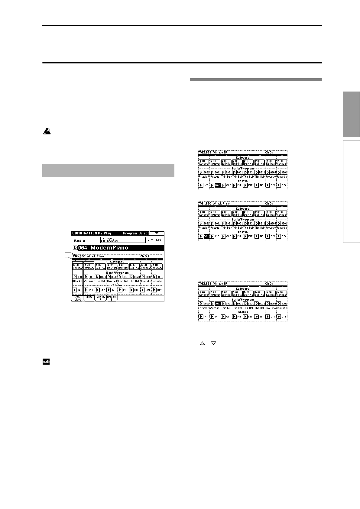
Simple combination editing
A combination is a set of multiple (up to eight) programs, and allows you to create complex sounds that
could not be produced by a single program.
You can edit a combination in Combination P1: Editprogram/Mixer–P9: Edit-Master Effect, but can also
make settings for “Program Select,” “Status,” “Pan,”
and “Volume” in Combination P0: Play as well.
If you wish to keep the results of your editing, you
must Write the combination into memory before
selecting another combination or turning the
power off. (
As an example, here’s how to do some simple editing
on combination Bank A064: ModernPiano.
1 Press the [COMBI] key to enter Combination
mode.
2 Select preset combination Bank A064: ModernPi-
ano.
☞p.38)
An example of editing
Selecting the program for a timbre
3 Press the Prog. Select tab.
When a timbre’s “Status” is turned Off, the pro-
gram assigned to that timbre will not sound. If the
“Status” is set to INT, the program will sound. Try
setting timbres 1 and 2 alternately to INT and Off,
and listen to the result.
Only timbre 1 will sound
Only timbre 2 will sound
Quick Start
Simple combination editing
Timbre 2
Timbre 1
This combination layers (simultaneously sounds)
the programs of timbre 1 and timbre 2. Timbre 1
sounds B001: Attack Piano, a piano with a crisp
attack. Timbre 2 sounds B081: Vintage EP, a classic
electric piano. These two programs are layered to
produce a piano-type sound that you may have
heard in various contexts.
A timbre consists a of program together with mul-
tiple parameters that control that program. A combination can use up to eight of these timbres.
4 Now let’s change the program of timbre 2 to a dif-
ferent program. (Make sure that the “Status” of
timbres 1 and 2 are set to INT.)
Press the timbre 2 “Bank/Program” switch (it will
be highlighted).
Use the [BANK] keys, numeric keys [1]–[9],
[ENTER] key, [VALUE] slider, [VALUE] dial, and
[ ][ ] keys to select a program.
Alternatively, you can select a program from a
popup menu. Press the popup button, and select the
desired program from the popup menu that
appears.
5 You can also select programs by category. Press
“Category” for timbre 2.
The “Category/Timbre2 Program” select menu will
appear. In this combination, a program from the
“Keyboard” category is selected for both timbres 1
and 2.
35
Page 40

● If you wish to select a different program from the
same category, press the desired program. That program will be highlighted. Press the scroll bar to see
other programs in the same category.
● If you wish to select a program from a different cate-
gory, press one of the tabs located at left and right to
select the desired category. The full name of the
selected category will appear in the upper right.
Let’s select the 03 Strings category. Press the 03
Strings tab, and then press the desired program to
select it. The program you pressed will be highlighted. Press the scroll bar to see other programs in
the same category.
For this example, select A003: Legato Strings. This
will produce a layered combination consisting of a
piano and rich strings.
8 Press timbre 2 “Pan” (it will be highlighted).
Use the numeric keys [0]–[9], [ENTER] key,
[VALUE] slider, [VALUE] dial, or [ ][ ] keys to
modify the value.
With a setting of C064 the sound will be located in
the center. A setting of L000 places the sound at the
far left, and R127 at the far right. With a setting of
RND, the sound will move randomly between left
and right each time a note is played.
Adjusting the volume
9 Press timbre 2 “Volume” (it will be highlighted).
Use the numeric keys [0]–[9], [ENTER] key,
[VALUE] slider, [VALUE] dial, or [ ][ ] keys to
modify the value.
If you check “Hold Balance” and adjust the “Volume” value, the volume balance between the timbres at the time that “Hold Balance” was checked
will be maintained while the volume of all timbres
is adjusted.
6 If you are satisfied with the selected program,
press the OK button to close the popup menu.
If you press the Cancel button, your selection will
be discarded, and you will return to the program
that had been selected when the popup menu was
opened. For this example, press the OK button.
Adjusting the stereo position
7 Press the Mixer tab.
36
Page 41
Basic functions
Saving data
Types of data that can be saved
On the TRITON, there are three ways to save data:
writing to internal memory, saving on external media
(floppy disk etc.), and MIDI data dump.
Writing to internal memory
The following data that you edit can be written into
internal memory.
• Program settings
Programs 0–127 in banks A–F
(However, bank F is available only if the separately
sold EXB-MOSS option is installed.)
• Combination settings
Combinations 0–127 in banks A–D
• Global settings (Page 0–4)
• User drum kits 00 (A/B)–63 (User)
• User arpeggio patterns U000 (A/B)–U231 (D)
• User template songs
Song settings such as the song name and tempo,
track settings (
effect settings can be saved (Write) to internal memory. However, the musical data for song tracks and
patterns are not saved to internal memory. Furthermore, settings that govern how the musical data is
played back such as “Meter,” “Metronome,” “Play/
Mute,” “Track Play Loop (including Start/End Measure),” and RPPR settings will not be saved either.
Use the Sequencer mode or Song Play mode page
menu command “Save as User Template Song” to
write this data (
If multisamples or samples from the RAM bank
are used in the Multisample or Drum Kit of a pro-
gram, you should be aware that these multisamples or samples cannot be written into memory.
This means that if you turn the power of and then
on once again, programs or combinations that use
such multisamples or samples will not sound as
intended. To reproduce such programs or combinations, the necessary multisamples or samples
must be saved on external media (such as floppy
disk), and then reloaded.
Data that you edit in Sequencer, Song Play, or Sampling cannot be saved in internal memory by the
Write operation.
Saving to external media (floppy disk etc.)
The following data can be saved on external media
(floppy disk etc.). If the separately sold EXB-SCSI
option is installed, this data can also be saved on highcapacity media such as a hard disk etc.
☞p.60), arpeggiator settings, and
☞p.48 in the Parameter Guide).
For details on the file format when saving (
the Parameter Guide).
• Programs, combinations, global settings, drum
kits, and user arpeggio patterns from internal
memory
• Songs, cue lists, and patterns
• Multisamples and sample data created in Sampling
mode
• Standard MIDI Files (SMF)
Sequencer mode songs can be saved as SMF data.
• System exclusive data
System exclusive data received by the TRITON from
an external MIDI device (The TRITON can function
as a data filer.)
• Jukebox lists
Jukebox lists are saved in Song Play mode (
Other data is saved in Disk mode.
☞p.139 in
☞p.88).
MIDI data dump
The following types of data can be transmitted as a
MIDI data dump and saved on an external data filer or
other device.
• Internal memory programs, combinations, drum
kits, arpeggio patterns, and global settings
• Songs, cue lists, patterns
Writing to internal memory
Memory protect
To prevent programs, combinations, songs, drum kits,
and user arpeggio patterns from being overwritten
accidentally, the TRITON provides a Memory Protect
setting that prohibits writing to memory.
Before you save edited data or load data from floppy
disk or other external media, use the following procedure to turn off memory protect (uncheck the appropriate check box).
Memory protect must also be turned off before the
above-listed data or a song in Sequencer mode can be
loaded from external media or via MIDI data dump,
and before recording.
1 Press the [GLOBAL] key to enter Global mode.
2 After pressing the [MENU] key, press either P0:
Basic Setup or the [0] key.
3 Press the System Pref. tab.
Basic functions
Saving data
37
Page 42

The System Preference page will appear.
Writing a program or combination
A program or combination that you create by editing
its settings in the Performance Editor or in the various
Edit pages can be saved in internal memory. This procedure is called Program Write or Combination Write.
If you wish to use the edited settings again after turning the power off, be sure to write the settings into
memory.
There are two ways to write a program or combination.
4 Press the “Memory Protect” check box for the type
of internal memory into which you wish to write
data, so that the box is unchecked.
Assigning a name (Rename)
You can modify the name of an edited program, combination, song, drum kit, user arpeggio pattern, multisample or sample etc.
You can also modify the category names for programs
and combinations.
These renaming operations can be performed in the
following pages.
Programs Program P0...9 Page Menu Com-
mand: Write Program
Combinations Combination P0...9 Page Menu Com-
mand: Write Combination
Songs SequencerP0, 2...4, 7 Page Menu
Command: Rename Song
Cue lists Sequencer P1 Page Menu Com-
mand: Rename Cue List
Tracks Sequencer P5: Track Name
Patterns Sequencer P6: Pattern Name
Multisamples Sampling P0...4 Page Menu Com-
mand: Rename MS
Samples Sampling P0...4 Page Menu Com-
mand: Rename Sample
Drum kits Global Page Menu Command P5:
Rename Drum Kit
User arpeggio patterns Global Page Menu Command P6:
Rename Arpeggio Pattern
Program categories Global P4: Program Cat.
Combination categories Global P4: Combination Cat.
Before you write data into memory, you must turn
off the memory protect setting in Global mode (
☞
“Memory protect”).
Using a page menu command to write
1 Press the “Write Program” or “Write Combination”
page menu command.
The Write Program/Write Combination dialog box
will appear.
You can also access the same dialog box by holding
down the [ENTER] key and pressing the [0] key.
The screen shown is for Program mode
If you wish to overwrite the edited settings onto
the currently selected program/combination with
the same program/combination name and program/combination category, simply press the OK
button in the dialog box.
2 If you wish to modify the program/combination
name, press the text edit button.
The text edit dialog box will appear.
Input the program/combination name.
Text
Cursor
Character Set
Selects the type of
character.
Character buttons
For details on the renaming procedure, refer to “Writing a program or combination.”
38
Cursor buttons
Move the cursor
to left or right.
Space button
Insert a space at the cursor
location.
Clear button
Delete all characters
of the text.
Shift button
Switches
between
uppercase and
lowercase
Delete button
Deletes the character
to the left of the
cursor.
Cancel button, OK button
If you are satisfied with the text
that you input, press the OK
button. If you wish to discard
your input and exit the text edit
box, press the Cancel button.
Page 43

When you have input the desired name, press the
OK button to return to the Write Program/Write
Combination dialog box.
3 In “Category,” specify the category of the program/
combination.
The category you specify here can be selected in the
Category/Program Select menu, the Category/
Track Program Select menu, or the Category/Timbre Program Select menu (when choosing a program), or in the Category/Combination Select
menu (when choosing a combination).
4 Use “To Program” and “To Combination” to spec-
ify the writing destination program/combination
number.
Use the [ ][ ] keys, [VALUE] slider, [VALUE]
dial, numeric keys [0]–[9], or [ENTER] key to make
your selection. Alternatively, you can press the
popup button and use the popup menu to specify
the writing destination bank and program/combination number.
When you press the front panel [COMPARE] key
in the edit pages P1–P9 of Program mode or Combination mode, the data from memory (i.e., the
contents that were written into memory) will be
temporarily called into the edit buffer. This allows
you to compare the settings you are editing with
the original un-edited settings.
Editing applies to the data in the edit
buffer. Programs or combinations will
play according to the data in the edit
buffer.
Edit
When you select a program or
combination, its data is called from
internal memory into the edit buffer.
When you Write, the program or
combination settings will be
saved in internal memory.
Program
BankA 0...127
Edit Buffer
Write
Select
Internal Memory
BankA 0...127
Combination
Combination
Combination
Combination
BankA 1...127
BankA 1...127
BankA 1...127
Writing global settings, user drum kits,
and user arpeggio patterns
Basic functions
5 To write the data, press the OK button. To cancel
without writing, press the Cancel button.
When you press the OK button, the display will ask
“Are you sure?” When you press the OK button
once again, the data will be written.
Using the [REC/WRITE] key to write
This method can only be used to write to the selected
program/combination number.
1 Press the front panel [REC/WRITE] key.
The following display will appear.
The screen shown is for Program mode
2 To write the data, press the OK button. To cancel
without writing, press the Cancel button.
About the Edit Buffer
When you select a program or combination in Program
P0: Play and Combination P0: Play, the program or
combination data is called into the “edit buffer.”
When you modify the parameters in P0: Play or in the
edit pages P1–P9, the changes you make will affect the
data in the edit buffer.
If you wish to save this modified data into internal
memory, you must perform the Write operation.
When you perform the Write operation, the data in the
edit buffer is written to the specified program number
or combination number of the specified bank.
If you select another program or combination without
writing, the data of the newly selected program or
combination will be called into the edit buffer, and
your changes will be lost.
The settings you edit in Global mode can be written
into internal memory. This is done using the operations
Write Global Setting, Write Drum Kits, and Write
Arpeggio Patterns. If you wish to use these settings
after turning the power off, be sure to write the data.
There are two ways to write global settings, user drum
kits, and user arpeggio patterns.
Before you write a user drum kit or user arpeggio
pattern, the Global mode memory protect setting
must be turned off (
☞“Memory protect”).
The user arpeggio pattern settings “Tempo,” “Pattern,” “Octave,” “Resolution,” “Sort,” “Latch,”
“Key Sync,” and “Keyboard” are parameters that
are set independently in Program, Combination,
Song, and Song Play mode. These settings are not
saved when you perform the Write operation
described here.
If you moved from Program or Combination mode
and set these parameters, you must return to the
original mode and write them.
Using a page menu command to write
1 To write global settings (Global P0–P4), press the
page menu command “Write Global Setting” in
Global P0–P4.
The Write Global Setting dialog box will appear.
To write user drum kits, press the page menu command “Write Drum Kits” in Global P5.
The Write Drum Kits dialog box will appear.
To write user arpeggio patterns, press the page
menu command “Write Arpeggio Patterns” in Global P6.
The Write Arpeggio Patterns dialog box will appear.
The same dialog box will also appear if, in each of
the above pages, you hold down the [ENTER] key
and press the [0] key.
Saving data
39
Page 44

The example shown is for Write Arpeggio Patterns
Saving on external media
For details on the data that can be saved on external
media (floppy disk etc.) (
be saved”).
☞p.37 “Types of data that can
2 To execute the Write operation, press the OK but-
ton. To cancel, press the Cancel button.
When you press the OK button, the display will ask
“Are you sure?” Press the OK button once again to
write the data.
Using the [REC/WRITE] key to write
1 In the following pages, press the front panel [REC/
WRITE] key. A dialog box will appear.
Global settings: Global P0–P4
User drum kits: Global P5
User arpeggio patterns: Global P6
The example shown is for Update Arpeggio Patterns
2 To execute the Write operation, press the OK but-
ton. To cancel, press the Cancel button.
Memory in Global mode
When the power is turned on, the Global mode data is
called from internal memory into the Global mode
memory area. Then when you modify the parameters
in Global mode, the data in the memory area will be
modified. If you wish to save this modified data in
internal memory, you must Write it.
When you write, the data in the memory area will be
written into the global settings, drum kits, and arpeggio patterns of internal memory.
If you turn off the power without writing, the modified
data in the memory area will be lost.
Editing will affect the data that has
When you Write, the various
Global mode settings will be
saved in internal memory.
Global Setting
been called into the memory area.
Memory Area
Write
Power On
Internal Memory
Drum Kit
Edit
When the power is turned
on, the settings are called
into the memory area.
Arpeggio
Pattern
Song data, patterns and cue lists in the TRITON’s
Sequencer mode, and multisamples and samples
in Sampling mode cannot be written into internal
memory. This data will disappear when the power
is turned off. If you wish to keep this data, you
must save it on a floppy disk or on other external
SCSI storage media (if the separately sold EXBSCSI option is installed).
Other types of data can also be saved on a floppy
disk, or (if the separately sold EXB-SCSI option is
installed) on external SCSI storage media (maximum 4 GB), and loaded to restore the original settings even if they have been modified. It is a good
idea to save favorite settings that you create.
As an example, we will explain how to save the
following data.
• Internal memory programs, combinations, global
settings, drum kits, user arpeggio patterns
• Songs, cue lists, patterns
• Multisamples and samples created in Sampling
mode
1 If you wish to save the data on a floppy disk, insert
a floppy disk into the TRITON’s floppy disk drive.
For details on floppy disk handling, be sure to refer
to “Cautions for floppy disk handling (
If the separately sold EXB-SCSI option is installed
and you wish to save the data on a hard disk or
other external SCSI media, refer to the EXB-SCSI
owner’s manual, and make sure that the external
SCSI drive etc. is connected correctly.
Format the disk if necessary (
☞p.142 in the Parame-
ter Guide)
2 Press the [DISK] key. You will enter Disk mode.
Drive select
button
☞p.95).
40
3 Press the Save tab, and the Save window will
appear.
4 If you are saving to external SCSI media, press the
drive select button to select the save destination
drive.
5 If the media contains directories, select the direc-
tor in which you wish to save the data.
Page 45

To move to a lower directory level, press the Open
button. To move to a higher level, press the Up but-
ton.
6 Press the page menu button, and then press the
“Save All” page menu command.
A dialog box will appear. The contents of the dialog
box and the settings etc. will differ depending on
the type of data that you are saving. For details on
each type of file (
7 Use the text edit button to input a name (
8 Use the check boxes to uncheck items that you do
not wish to save.
In order to accurately reproduce the data you created, we recommend that you leave all check boxes
checked.
9 Press the OK button.
The data will be saved on the specified media, and
you will return to the Save page. The amount of
time required will depend on the amount of data.
If a file with the same name already exists on the
floppy disk, you will be asked whether you want to
Overwrite. If you wish to overwriting, press the OK
button. If you wish to save without overwriting, press
the Cancel button, re-do the operation from step 6,
and rename the data in step 7 before saving it.
The LCD screen will show the files that were saved.
The data will be saved as the following files.
☞p.139 in the Parameter Guide).
☞p.38).
.SNG file
Sequencer songs, cue lists, and user patterns
.KSC file
A file which lists the multisamples and samples
used
Directory
A directory containing the multisamples (.KMP
files) and samples (.KSF files) that are listed in the
.KSC file
Other ways to save
In addition to “Save All,” the page menu commands
include “Save PCG which saves programs, combinations, drum kits, user arpeggio patterns, and global settings; “Save SEQ” which saves only sequencer songs,
cue lists, and user patterns; and “Save Sampling Data”
which saves only multisamples and samples. Select the
appropriate page menu command for the data that you
wish to save on external media.
When using “Save All,” “Save PCG & SNG,” and
“Save PCG” to save combinations, you should also
remember to save the programs used by each timbre (and the drum kits used by the programs) and
user arpeggio patterns at the same time.
Similarly when saving programs, you should also
remember to save the drum kits and user arpeggio
patterns used by the programs.
If your programs or drum kits use multisamples
and samples that were created in Sampling mode,
we recommend that you use “Save All” to save the
data.
When you use “Save PCG” or “Save Sampling
Data” to individually save a program or drum kit,
or a multisample or sample that you created in
Sampling mode, we recommend that you save
them under the same filename in the same directory. When you use “Load PCG” to load a .PCG
file, the identically-named .KSC file will also be
loaded so that the correct multisamples/samples
will correspond automatically.
When saving .KSC, .KMP, and .KSF files and the
data does not fit on a single floppy disk (or other
volume of media), another dialog box will appear,
and you will be asked to specify the next volume
of media (
other medium”)
☞p.141 in the Parameter Guide “Select
Basic functions
Saving data
.PCG file
Programs, combinations, drum kits, user arpeggio
patterns, and global settings that were saved in
internal memory
MIDI data dump
The programs, combinations, drum kits, arpeggio patterns and global settings of internal memory, and
songs, cue lists, and patterns can be transmitted as
MIDI exclusive data and saved on a connected MIDI
data filer, computer, or another TRITON.
☞ p.119 in the Parameter Guide.
41
Page 46

Restoring the factory settings
The factory setting data is referred to as the “preload
data”, and you can restore the factory settings for the
TRITON’s programs, combinations, and global settings
by loading this preload data.
This will rewrite any data that had been written
before loading. If you do not wish to lose this data,
you must first save it on a floppy disk or (if the
separately sold EXB-SCSI option is installed) on
external SCSI media (
☞p.40).
Loading the preload data
1 Insert the included TNFD-00P floppy disk into the
floppy disk drive.
For details on floppy disk handling, refer to “Disk
mode” (
2 Press [DISK].
You will enter Disk mode.
3 Press the Load tab.
You will move to the Load page, and file information will be displayed.
4 Press “PRELOAD.PCG.” The display will be high-
lighted.
☞p.95).
6 If “Load PRELOAD.SNG too” is checked when
you load, the .SNG file will also be loaded when
the .PCG file is loaded.
If you check “Load PRELOAD.KSC too” is
checked when you load, the .KSC file will also be
loaded when the .PCG file is loaded.
For details on the files that are loaded by the .KSC
file, refer to “Listening to a demo song” (
7 Press the OK button.
☞p.18).
A .PCG file contains programs, combinations, drum
kits, arpeggio patterns, and global setting data.
5 Press the page menu button to display menu com-
mands, and select “Load Selected.”
A dialog box will appear.
42
Page 47

Program mode
About the pages in Program
mode
In Program mode you can select and edit programs.
Program mode consists of pages P0–P9.
In P0: Play you can play programs. You can also perform simple editing (
In P1–P9, you can edit the parameters of the program
that was selected in P0.
● For details on how to access these pages or modes,
refer to “Basic operation of the TRITON” (
P0: Play Select a program, use the Perfor-
P1: Edit-Basic Set basic program parameters such
P2: Edit-Pitch Settings related to the pitch, including
P3: Edit-Filter Settings related to the filter (tone),
P4: Edit-Amp Settings related to the amplifier (vol-
P5: Edit-Common LFO For each of the two LFO’s provided for
P6: ---
P7: Edit-Arpeggiator Settings for the arpeggiator. (Some of
P8: Edit-Insert Effect Select inser t effects and make set-
P9: Edit Master Effect Select master effects and make set-
If the separately sold EXB-MOSS has been
installed, you will be able to use bank F. The page
structure and parameter structure of bank F programs is different than for the programs of other
banks. Refer to the owner’s manual for the EXBMOSS.
When it is shipped from the factory, the TRITON is
loaded with a variety of preset programs. You can create your own programs by modifying these factorypreset programs or by creating original programs from
scratch. You can also create original programs using
sample waveforms and multisamples that you
☞p.34).
☞p.12).
mance Editor to perform simple editing, and select and set arpeggio
patterns.
as oscillator and multisample. Set
scale and controllers.
the pitch EG.
including the filter EG.
ume), including amp EG and pan.
each oscillator, select the LFO type
and speed, etc. (Settings in the pitch,
filter, and amp pages will determine
how deeply the LFO that you specify
here is applied.)
these are shared with the arpeggiator
settings of P0, and you may edit them
in either location.)
tings for them. Specify the oscillator
routing (send levels to the insert
effects, master effects, and independent outputs).
tings for them. Make settings for the
master EQ.
recorded in Sampling mode or loaded into memory in
Disk mode.
Programs that you edit or create can be written into the
640 program memory areas in banks A–E. In Disk
mode, programs can also be saved on external media
such as floppy disk (
☞p.40).
The TRITON provides AUDIO INPUT jacks that
allow an external audio source to be input. In
addition to sampling the external audio input in
Sampling mode, you can apply the TRITON’s
effect section to the external audio input in other
modes such as Program mode, or even use
vocoder effects that combine the sound of an oscillator with an external audio source (
(
☞p.201 in the Parameter Guide)
☞p.109).
All transmission and reception of MIDI data in
Program mode is performed on the Global MIDI
channel. The global MIDI channel is set in Global
mode P1: MIDI “MIDI Channel.”
Playing a program
P0: Play
Here you can select and play programs. You can also
use the Performance Editor to do some simple editing,
and make arpeggiator settings.
Selecting a program
There are three ways to select a program. For the procedure, refer to the appropriate page.
• Using the controls of the TRITON (“Selecting and
playing a program”
Selecting by bank/program number
Selecting by program category
Selecting with 10’s Hold
• Using a connected switch (“Other functions”
☞p.125)
• Receiving MIDI program change messages
(“MIDI”
☞p.114)
For the names of the factory-set programs, refer to
the separate Voice Name List.
The Performance Edit tab
• Here you can view the insert/master effect
settings, the functions of [SW1], [SW2] keys, and
the B-mode functions of REALTIME CONTROLS
knobs [1]–[4].
• You can use the performance editor to adjust the
major parameters of Program P1–P9 (
“Performance Edit” on p.2 in the Parameter Guide).
If you wish to save the program settings that you
☞p.21)
☞p.34, or
Basic functions
Program mode
43
Page 48
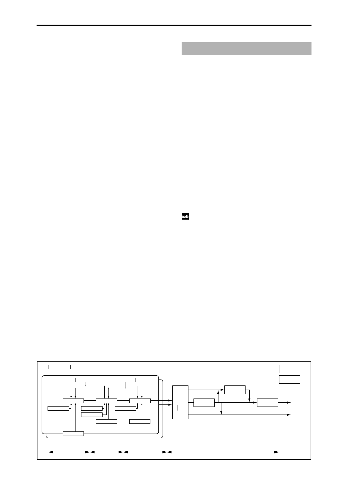
modify using the performance editor, you must
turn off memory protect in Global mode (
and write the program (
☞p.38).
☞p.37),
The Arpeggio tab
• Use the ARPEGGIATOR [ON/OFF] key to turn the
arpeggiator on/off.
• You can select arpeggio patterns and edit
arpeggiator parameters in realtime while you play.
• You can use the ARPEGGIATOR [TEMPO],
[GATE], and [VELOCITY] knobs to control the
tempo of the arpeggio, the note length, and the
strength of the notes.
For details refer to “Using the arpeggiator while you
play” (
☞p.29).
How a program is organized
A program consists of the many parameters of P1–P9.
The diagram below shows the structure of a program.
Sound has three aspects: pitch, tone, and volume.
On the TRITON, the Pitch, Filter, and Amplifier blocks
which make up a program correspond to these three
aspects of sound. In other words, adjust the Pitch section to modify the pitch, adjust the Filter section to
modify the tone, and adjust the Amplifier section to
modify the volume.
First, make Oscillator settings (P1: Edit-Basic) to select
a multisample waveform that will be the basis of the
sound. Then make pitch settings (P2: Edit-Pitch), filter
settings (P3: Edit-Filter) and amplifier settings (P4:
Edit-Amp) to create the basic program. (This is the program as it is used in Combination, Sequencer, or Song
Play mode.) To this, you can add insert effect settings
(P8: Edit-Insert Effect), master effects and master EQ
settings (P9: Edit-Master Effect) to add finishing
touches to the sound. You can also make arpeggiator
settings (P7: Edit-arpeggiator) and controller settings
(P1: Edit-Basic, Controller tab) to create the final pro-
gram.
Program Basic : P1 - 1
OSC Basic : P1 - 2,3
OSC1 Pitch Mod. : P2 - 1
OSC1 LFO1 : P5 - 1
Filter1 Mod. : P3 - 2
Filter1 LFO Mod. : P3 - 3
Filter1(A/B) : P3 - 1
Filter1 EG : P3 - 4
OSC1 LFO2 : P5 - 2
Amp1 Level/Pan : P4 - 1
Amp1 Mod. : P4 - 2
Amp1 EG : P4 - 3
Routing : P8-1
OSC1,2
Insert Effect
Master Effect
Individual Output
For programs that are used in Combination,
Sequencer, and Song Play mode, settings for insert
effects, master effects, master EQ, arpeggiator, and
controllers must be made separately from the settings made in Program mode.
Controller Setup:
P1 - 4
Arpeggiator : P7
Master Effect 1, 2 :
P9
Insert Effect 1 ... 5 :
P8
MasterEQ : P9
AUDIO OUTPUT
L/MONO, R
AUDIO OUTPUT
INDIVIDUAL 1,2,3,4
44
Pitch EG : P2 - 3
Oscillator / Pitch
Filter
Ampilfier
OSC 1
OSC 2
Effect
P1–1 and P2–2 etc. indicate the page tab screens used when editing on the TRITON.
Page 49

Basic program editing
Program editing refers to the process of modifying the
parameters that make up a program to vary the sound
or to set controllers etc.
General program editing can be performed using the
performance editor of Program P0: Play, or using the
REALTIME CONTROLS knobs [1]–[4], but detailed
editing is performed in Program P1–P9.
Use the parameters of P1–P9 to edit the program that
you selected in Program P0: Play. In this section we
will give examples of how to modify representative
parameters in each page, so that you can understand
the operation of each parameter. For details on all
parameters, refer to in the Parameter Guide.
For parameters in P1–P5 that are set independently for each oscillator 1 and 2, you can use the
page menu command “Copy Oscillator” to copy
settings from one oscillator to the other. This is a
convenient way to make the same settings for two
oscillators, or to copy settings from one oscillator
to the other.
If you wish to save an edited program into internal
memory, be sure to Write the program. (
If the separately sold EXB-MOSS option is
installed, you will be able to use the special bank F.
The parameter structure of bank F programs is different than that of the other banks. Refer to the
EXB-MOSS owner’s manual.
☞p.38)
Program Basic tab
Oscillator Mode
This sets the mode of the oscillator. Single uses one
oscillator and Double uses two oscillators. In the case
of Single the maximum polyphony is 62 notes, and in
the case of Double the maximum polyphony is 31
notes. If you wish to use a Drum Kit to create a drums
program, select Drums.
Voice Assign Mode
Select whether the program will sound in Poly (poly-
phonically) or Mono (monophonically). If this is set to
Poly, you will be able to play chords using the program. If this is set to Mono, only one note will sound
even if you play a chord. Normally you will set this to
Poly, but it is effective to use Mono when you are play-
ing sounds such as analog-synth bass or synth lead.
Try switching between Poly and Mono, and listen to
the result.
OSC Basic tab
Basic functions
Program mode
The Compare function
When P1–P9 are displayed, you can press the [COMPARE] to make the LED light. This will recall the
sound that had been written before you started editing.
Press the [COMPARE] key once again and the LED will
go dark, and you will return to the sound that you had
been editing. Use this function when you wish to compare the unedited sound with the results of your editing.
When the [COMPARE] key LED is lit, editing a
parameter will make the LED go dark, and that
sound will now be the sound that is recalled when
the [COMPARE] key LED is dark.
P1: Edit-Basic Oscillator settings
In P1: Edit-Basic you can make oscillator-related settings. The TRITON provides two oscillators, and for
each oscillator you can select a basic waveform (“mul-
tisample”) and set the pitch. The multisamples provided by the TRITON include waveforms for musical
instruments such as pianos, as well as special waveforms unique to synthesizers. Multisamples reproduce
the complex overtone structure and frequency characteristics that allow us to identify a sound as being
“piano-like” or “guitar-like.”
Multisample
Select
In this page you can select the multisample for the
oscillator. The TRITON provides 425 multisamples in
its internal ROM memory. For the multisample names,
refer to the separate Voice Name List.
Additional multisamples can be added by installing a
separately sold EXB-PCM series option board. You can
also use multisamples from the RAM memory that you
created in Sampling mode.
Selecting a multisample
The multisample will determine the basic character of
the program.
● Press “Multisample Select” (it will be high-
lighted), and use the [ ][ ] keys, [VALUE]
slider, [VALUE] dial, numeric keys, and [ENTER]
key, [0]–[9] to select the desired multisample.
45
Page 50

If you press the popup button, all multisamples of
internal ROM will be displayed, grouped into fifteen categories.
Use the tabs at left and right to select a category,
and select the desired multisample.
About High/Low
You can specify two multisamples for an oscillator, and
use velocity (keyboard playing dynamics) to switch
between the two multisamples. This capability is called
“velocity multisample switching.”
1 Select different multisamples for “High” and
“Low.”
2 Set the “Velocity M.Sample SW Lo → Hi” parame-
ter to set a value of (for example) 100 for OSC1.
The Low and High multisamples will be switched
at this velocity value.
3 Play the keyboard softly, and the multisample
specified for “Low” will sound.
4 Play the keyboard strongly, and the multisample
specified for “High” will sound.
When “Oscillator Mode” = Drums
In the Program Basic tab, set “Oscillator Mode” to
Drums. When this is set to Drums, you will be able to
create a drum program.
This will select a drum kit instead of a multisample.
The TRITON provides sixteen factory preset drum kits
that are suitable for a wide variety of music. For the
drum kit names, refer to the separate Voice Name List.
Here you can only select a drum kit. To edit or create a
drum kit, use Global P5: Drum Kit (
☞p.90).
5 Adjust the “Lvl” (level) for “High” and “Low”
multisamples to set their volume balance.
If you do not wish to use this function, set the
“Velocity M.Sample SW Lo → Hi” value to 001.
Only the High multisample will sound.
Rev (Reverse) check box
If this is checked, the multisample will be played backward. This can produce interesting results when used
on sound-effects, etc. Normally you will not check this.
When “Oscillator Mode” = Double
To use OSC2, set “Oscillator Mode” to Double in the
Program Basic tab.
In the same way as for OSC1, you can set High and
Low multisamples for OSC2.
The playback pitch can be set independently. By using
the same multisample with slightly different “Tune”
settings, you can “detune” the oscillators to produce a
richer sound.
It will be convenient to use the page menu command “Copy Oscillator” to make the oscillator settings match each other.
Velocity Zone tab
Here you can specify the range of velocities that will
sound oscillators 1 and 2. In the example shown above,
the velocity ranges are as follows.
• OSC1 will sound for all velocity values.
• OSC2 will sound only for strongly played notes (64
and above).
• You can use Velocity Multisample Switching in
addition to this (
example, set “OSC1” in “Velocity M.Sample SW
Lo→Hi” to 032 and “OSC2” to 096. The settings are
shown as horizontal lines in the velocity zone
display.
In this example, the multisamples will sound over
four levels.
☞“About High/Low”). For this
46
Velocity values 001–031: sound only the OSC1 Low
multisample.
Velocity values 032–063: sound only the OSC1
High multisample.
Velocity values 064–095: sound the OSC1 High
multisample and the
OSC2 Low multisample.
Velocity values 096–127: sound the OSC1 High
multisample and the
OSC2 High multisample.
Page 51

Controller Setup tab
For each program, this tab lets you make settings for
the [SW1] and [SW2] keys, and for the B-mode of
REALTIME CONTROLS knobs [1]–[4] (
☞p.127). (☞p.8,
217, 218 in the Parameter Guide)
P2: Edit-Pitch Pitch settings
Here you can specify how the pitch of the multisample
selected for the oscillator will change. Pitch EG and
LFO settings allow the pitch to varied over time. When
the “OSC Mode” is Single or Drums, only the OSC1
P.Mod. tab is available.
LFO 1/2
An LFO can be used to cyclically modulate the pitch
(the “vibrato” effect).
“LFO Intensity” specifies the amount of pitch change
that the LFO will produce. With a setting of +12.00,
vibrato will produce a maximum of ±1 octave of pitch
change.
“JS+Y Int” specifies the amount of vibrato that the LFO
will produce when the joystick is pushed away from
yourself.
“AMS Intensity” specifies the amount of vibrato that
the LFO will produce when an AMS (alternate modulation source) is operated. For example if “AMS” is set
to After Touch, vibrato will be applied when you
apply pressure to the keyboard.
OSC1 Pitch Mod. tab
Pitch
JS(+X) and JS(-X) specify the amount of pitch change
that will occur when the joystick is moved to right or
left, in semitone units. With a setting of +12 the pitch
can be raised a maximum of one octave, and with a setting of –12 the pitch can be lowered a maximum of one
octave.
“Pitch Ribbon” specifies the amount of pitch change
that will occur when you operate the ribbon controller
toward the left or right. With a setting of +12, moving
your finger to the right edge will raise the pitch one
octave, and moving your finger to the left edge will
lower the pitch one octave.
Pitch EG
When the “Intensity” value is set to +12.00, the pitch
EG specified in the Pitch EG tab will produce a maximum of ±1 octave of pitch change.
Portamento
If “Enable” is checked, portamento will be applied.
Portamento makes the pitch change smoothly when
you play the next note before releasing the previous
note.
The “Time” parameter specifies the portamento time.
As this value is increased, the pitch will change over a
longer time. With a value of 000, there will be no porta-
mento.
Pitch EG tab
Here you can make settings for the pitch EG.
When you wish to create sound effects etc., set the
pitch EG to make major changes in pitch over time.
To realistically simulate the slight change in pitch that
occurs when a string is plucked or at the attack of a
brass or vocal sound, you can use the pitch EG to create a subtle change in pitch at the attack (
Parameter Guide).
EG and LFO
When controlling the pitch, filter, and amplifier, the EG
(envelope generator) and LFO (low frequency oscillator) are used to create time-varying and cyclical
changes.
EG (Envelope Generator)
The TRITON provides a Pitch EG, Filter EG, and
Amplifier EG, which produce time-varying changes in
pitch, tone, and volume respectively.
note-on
Attack Level
Level
Decay Time
Attack Time
Start Level
LFO (Low Frequency Oscillator)
For each oscillator, the TRITON provides two LFO’s
that can be used to apply cyclical change in pitch, tone,
and volume.
Examples of this are “vibrato” (cyclical change in
pitch), “wah” (cyclical change in tone), and “tremolo”
or “auto-pan” (cyclical change in volume).
Break Level
Sustain Level
Slope Time
☞p.10 in the
note-off
Release Level
Release Time
Time
Basic functions
Program mode
If Porta.SW CC#65 is assigned as the function of
[SW1] or [SW2] key, the portamento effect can be
switched on/off by [SW1] or [SW2] key.
47
Page 52

P3: Edit-Filter Filter settings
The filter allows you to diminish or emphasize specified frequency areas of the multisample selected for the
oscillator. The tone of the sound will depend significantly on the filter settings.
The TRITON lets you choose between two types of filter for each oscillator. Filter 1 is used for OSC1, and Filter 2 is used for OSC2. If “OSC Mode” is Single or
Drums, only Filter 1 will be available.
Filter EG and LFO can be used to produce time-varying changes in the filter.
Level
Filter 1 tab
Overtones included
in the original multisample
Frequency (pitch)
Filter
Level
Filter characteristics
This area of
overtones will
be diminished
Overtones after
passing through
the filter
Frequency (pitch)
High pass filter
This type of filter passes the high frequency range and
cuts the low frequency range. Use this when you wish
to make the sound thinner. However if the cutoff frequency (Frequency) is raised excessively high, the volume will become very low.
High Pass
Level
12dB/oct
Frequency
Resonance
When “Resonance” is set to a higher value, the overtones in the region of the cutoff frequency will be
boosted as shown in the diagram below, giving a distinctive character to the sound.
When resonance is applied
Low Pass
Level
Low resonance value High resonance value
Filter Type, Filter A, Filter B
Select the type of filter, and specify the “Frequency”
(cutoff frequency) and “Resonance” (resonance level).
• Low Pass Resonance (24 dB/oct low pass filter
with resonance): Make settings for filter A.
• Low Pass & High Pass (12 dB/oct low pass filter
and 12 dB/oct high pass filter in series connection):
Make low pass filter settings in filter A, and high
pass filter settings in filter B.
Low pass filter
This is the most common type of filter, which passes
the low frequency range and cuts the high frequency
range. When the overtones of the high range are cut, a
bright sound will become darker (more mellow).
24 dB/oct and 12 dB/oct refer to the steepness of the
cut. 24 dB/oct means that the gain will decrease 24 dB
in one octave (i.e., as the frequency doubles). A 12 dB/
oct filter would decrease the gain 12 dB in one octave.
The 24 dB/oct filter produces a steeper cut.
Low Pass
Level
12dB/oct
24dB/oct
Frequency
Filter 1 Mod. tab
Controllers and the filter EG can be used to modulate
the filter cutoff frequency that was specified in the Filter 1 tab. By using a controller to vary the tone or by
using an EG to create time-varying changes, you can
add a rich variety of tonal change to the sound.
Keyboard Track
This varies the cutoff frequency according to the keyboard location that you play.
• When “Ramp Low” is set to a positive (+) value,
the cutoff frequency will rise as you play lower on
the keyboard, making the sound brighter. When
set to a negative (–) value, the cutoff frequency will
fall as you play lower on the keyboard, making the
sound darker.
• When “Ramp High” is set to a positive (+) value,
the cutoff frequency will rise as you play higher on
the keyboard, making the sound brighter. When
set to a negative (–) value, the cutoff frequency will
fall as you play higher on the keyboard, making
the sound darker.
48
Page 53

• “Intensity to A” and “Intensity to B” adjust the
effect that keyboard tracking will have on filters A
and B (
☞p.13 in the Parameter Guide).
Filter EG
Adjust the effect produced by the filter EG, whose settings are made in the Filter 1 EG tab.
• “Velocity to A” and “Velocity to B” adjust the
effect that velocity will have on the filter EG depth.
• “Intensity to A” and “Intensity to B” adjust the
depth of the filter EG.
• “AMS Int to A” and “AMS Int to B” adjust the
effect that AMS will have on the filter EG depth.
These three settings will determine the depth of the
tonal change produced by the filter EG.
Filter A/B Modulation
Set this when you wish to produce tonal change by
using controllers etc. to vary the cutoff frequency.
Filter 1 LFO Mod. tab
Make settings that allow the LFO to produce cyclic
changes in tone (a “wah” effect).
P4: Edit-Amp Amplifier settings
These settings affect the volume. Here you can adjust
the way in which the Amp EG and LFO produce timevarying and cyclic changes in volume, and how the
controllers etc. will affect the volume.
Amp1 applies to OSC1, and Amp2 applies to OSC2. If
the “OSC Mode” is Single or Drums, only Amp1 will
be available.
For example, the volume of a piano note begins at a
high volume the instant you play the note, and then
decreases gradually. The volume of an organ note
remains constant as long as you continue pressing the
key. The volume of a note on a violin or wind instrument can be varied during the note by the musician
(i.e., by regulating the amount of pressure on the bow
or the force of the breath).
Volume
Piano
Volume decays gradually
Volume
Time
Organ
Volume remains constant
until note is released
Time
Basic functions
“LFO Intensity to A” and “LFO Intensity to B” will
cause the tone to be modulated.
“JS–Y Intensity to A” and “JS–Y Intensity to B” specifies the depth of the wah effect that is produced when
you move the joystick toward yourself.
“AMS Intensity to A” and “AMS Intensity to B” specifies the depth of the wah effect that is produced when
you operate an “AMS” (alternate modulation source).
For example if you set “AMS” to After Touch, a wah
effect will be produced when you apply pressure to the
keyboard.
Filter 1 EG tab
Make settings for the filter EG, which controls timevariant changes in tone. Make settings for the EG here,
and set the depth of its effect in the Filter 1 Mod. tab
“Filter EG” parameter (
Filter EG and Amplifier EG
When the Filter EG changes the cutoff frequency, the
tone will change. However depending on the volume
changes produced by the Amplifier EG, this can be
heard in different ways. For example by changing the
speed at which the tone and volume begin (attack) or
decay, you can significantly vary the character of the
tonal change. It is a good idea to adjust the changes of
both the Filter EG (tone) and the Amplifier EG (volume) as you proceed with editing. (
☞p.15 in the Parameter Guide).
☞“Amp 1 EG” tab.)
Amp1 Lvl/Pan tab
Program mode
Amp Level
Adjust the volume of the sound that has passed
through the oscillator, filter, and amp.
Pan
Adjust the pan (stereo position) of the sound that has
passed through the oscillator, filter, and amp. Normally this will be set to C064. If “OSC Mode” is Dou-
ble and you wish to produce a sense of stereo, you can
use this setting to place oscillators 1 and 2 at the left
and right. With a setting of Random, the sound will be
placed at a random location each time you play a note,
producing an interesting effect.
AMS Intensity
“AMS Intensity” specifies the depth of the panning
effect that will occur when “AMS” is operated.
When “AMS” is set to Note Number, the pan will
change according to the location you play on the keyboard. With a setting of LFO1 or 2, the pan will sweep
from side to side (auto pan). Other settings allow you
to move the oscillator pan by operating a controller.
49
Page 54

Use DKit Setting
This is valid when “OSC Mode” is set to Drums. If this
is checked, the pan location specified by the Drum Kit
for each drum sound will be used. If this is unchecked,
all drum sounds will sound at the same location. Preset
drum kits are set to stereo settings. Normally you will
leave this checked.
Amp1 Mod. tab
Keyboard Track
This lets you vary the volume by the keyboard location
you play.
• When “Ramp Low” has a positive (+) value, the
volume will increase as you play lower on the
keyboard. With a negative (–) value, the volume
will decrease as you play lower on the keyboard.
• When “Ramp High” has a positive (+) value, the
volume will increase as you play higher on the
keyboard. With a negative (–) value, the volume
will decrease as you play higher on the keyboard.
sample, you can produce a sound with a character
unlike a typical organ.
Piano
Organ
Strings
P5: Edit-Common LFO LFO settings
For each oscillator, you can use two LFO (Low Frequency Oscillator) units: LFO1 and LFO2. You are free
to select the type of each LFO and set its speed. The
depth of the LFO1 and LFO2 whose settings you make
here can be adjusted in pages P2: Edit-Pitch, P3: EditFilter, and P4: Edit-Amp.
Amp Modulation
“Velocity Intensity” is used by most programs to
decrease the volume of softly played notes and
increase the volume of strongly played notes, and this
Amp Modulation parameter adjusts the depth of this
control. Normally you will set Amp Modulation to
positive (+) values. As this setting is increased, there
will be greater volume difference between softly
played and strongly played notes.
LFO 1/2
Specify how the LFO’s will produce cyclic changes in
volume (the tremolo effect).
The volume will be affected by the LFO(s) for which
you set an “LFO Intensity” value.
“AMS Intensity” adjusts the depth by which the tremolo effect produced by the LFO will be affected when
you operate an “AMS” (alternate modulation source).
For example if “AMS” is set to JS–Y, moving the joy-
stick toward yourself will apply tremolo.
Amp1 EG tab
Here you can make settings for the amplifier EG that
produces changes in volume over time.
Every instrument has its own characteristic curve of
volume change. This is part of what gives each instrument its identifiable character. Conversely, by applying
a strings-type Amp EG curve to an organ-type multi-
OSC (1/2) LFO (1/2)
“Waveform” selects the type of LFO. You can choose
from a variety of waveforms, including standard
waveforms such as Triangle, Saw, Square, and Sine, as
well as Step or Random waveforms that produce a
sample-and-hold effect (
A wide range of variations can also be produced using
the “Offset,” “Fade,” and “Delay” parameters, and by
changing the sign of the “Intensity” parameters in P2:
Edit-Pitch, P3: Edit-Filter, and P4: Edit-Amp. “Frequency” sets the speed of the LFO.
☞p.20 in the Parameter Guide).
Frequency Modulation
“AMS” can be used to vary the LFO speed. This lets
you change the LFO speed by operating a controller, or
by the EG or Keyboard Track settings.
Frequency MIDI/Tempo Sync.
If “MIDI/Tempo Sync” is checked, the “Frequency”
setting will be ignored, and the LFO will synchronize
to the tempo of the arpeggiator or sequencer. This lets
you produce vibrato, wah, auto-pan, or tremolo that is
synchronized to the playback speed of the arpeggiator.
50
Page 55

P7: Edit-arpeggiator
Arpeggiator settings
Here you can make arpeggiator settings (☞p.96).
P8: Edit-Insert Effect
Insert Effect settings
Here you can select insert effects and make settings for
them. You can also specify the oscillator routing (the
signal sent to the insert effects, master effects, and
independent outputs) (
☞p.107).
P9: Edit Master Effect
Master Effect settings
Here you can select master effects and make settings
for them. The master EQ is also set here (
☞p.108).
More about Alternate Modula-
tion
Alternate Modulation is a type of modulation that can
be used to control various aspects of the sound.
AMS (Alternate Modulation Source) refers to any of
the numerous sources that can control alternate modulation, and includes controllers such as the joystick or
ribbon controller that you physically operate, incoming MIDI data, as well as modulators such as the EG or
LFO.
Since the TRITON allows you apply modulation to a
modulator, this type of control is referred to as “alternate modulation.”
Intensity is a parameter that sets the degree (speed or
depth) to which AMS will control alternate modulation.
Combinations that are frequently used in sequencer
performance (such as using the joystick or ribbon controller to vary the pitch) are also provided as special
parameters separately from alternate modulation.
The TRITON provides 29 types of alternate modulation.
In single mode you can use 29 alternate modulation
destinations of 29 types, and in double mode you can
use 55 alternate modulation destinations of 29 types.
There are 42 AMS sources. (However depending on the
type of modulation, some sources cannot be selected.)
For details on alternate modulation and AMS, refer to
p.209 in the Parameter Guide.
Basic functions
Program mode
Suggestions on using alternate modulation
When making settings for alternate modulation, think
of the effect that you wish to produce, what type of
modulation will be necessary to produce that effect,
and what parameter of the oscillator, filter, or amplifier
needs to be controlled. Then select a source (“AMS”)
and set the “Intensity.”
If you proceed logically in this way, you will achieve
the desired effect.
For example if you want to “control a guitar-like sound
so that it appears to be approaching feedback when the
joystick is moved away,” you will make settings so that
the joystick controls filter modulation or the resonance
level.
51
Page 56

Combination mode
Pages in Combination mode
In Combination mode you select combinations and
edit them. Combination mode consists of pages P0–P9.
To play a combination, select P0: Play. In P1–P9 you
can edit the parameters of the combination that was
selected in P0.
● For details on accessing each page or modes (
“Basic operation of the TRITON”).
P0: Play Select a combination; select a program
P1: Edit-program/
Mixer
P2: Edit-Trk Param Set various parameters for each timbre,
P3: Edit-MIDI Filter MIDI transmission/reception filter set-
P4: Edit-Zone/Ctrl Key zone and velocity zone settings for
P5: ---
P6: ---
P7: Edit-Arpeggiator Arpeggiator settings. (These are com-
P8: Edit-Insert Effect Select insertion effects and make set-
P9: Edit Master Effect Select master effects and make set-
for each timbre; set the status, pan, and
level; select and set the arpeggio pattern.
Select a program for each timbre, and
set pan and level. (These are common
to the parameters in P0, and can be
edited from either page.)
such as MIDI, OSC, Pitch etc.
tings for each timbre.
each timbre. Make controller settings. If
the separately sold EXB-MOSS option
is installed, set related parameters.
mon to the parameters in P0, and can
be edited from either page.)
tings. Specify the timbre routing (send
levels to the insertion effects, master
effects, and independent outputs).
tings. Also make master EQ settings.
If the separately sold EXB-MOSS option is
installed, bank F programs can be used by the timbres of a combination. For details on the parameters of bank F programs, refer to the EXB-MOSS
owner’s manual.
☞p.12
disk or on other external media (
☞p.40).
Playing a combination
P0: Play
Here you can select and play combinations. For each
timbre 1–8, you can also select the program and set its
status, pan, and level. You can also make arpeggiator
settings.
Selecting a combination
There are three ways to select a combination. For the
procedure, refer to the appropriate page.
• From the TRITON’s front panel (“Selecting and
playing a combination”
Selecting by bank/combination number
Selecting by combination category
Selecting with [./10’s HOLD]
• With a connected foot switch (“Other functions”
☞p.125)
• By receiving MIDI program change messages
(“MIDI”
☞p.115)
For the factory-set combination names, refer to the
separate Voice Name List.
Program Select tab
Selecting a program for each timbre 1–8
There are three ways to select a program for each timbre 1–8. For the procedure, refer to the appropriate
page.
• From the TRITON’s front panel (“Simple
combination editing”
Selecting by bank/program number
Selecting by program category
• By receiving MIDI program change messages
(“MIDI”
☞p.115)
☞p.23)
☞p.35)
When the TRITON is shipped from the factory, it contains a wide variety of factory preset combinations that
use the preset programs, preset arpeggio patterns, and
effects. You can create your own combinations by modifying these preset combinations, or by creating a combination from scratch by starting with an initialized
combination.
Your own programs that use original sample waveforms or multisamples that were sampled in Sampling
mode or loaded into the TRITON in Disk mode can
also be used by a combination.
Combinations that you edit or create can be written
into the 512 combination memory areas of banks A–D.
In Disk mode, you can save combinations on a floppy
52
It is not possible to use MIDI program changes to
select a program on a Timbre whose “Status” is
other than INT.
If a program currently being edited in Program
mode is used in a combination, the combination
will use the sound that is being edited.
For the factory-set program names, refer to the separate Voice Name List.
Page 57

Status
For each timbre 1–8, this indicates the status of MIDI
and the internal tone generator. Normally, you will set
this to INT if you want the TRITON’s internal tone
generator to sound. Turn this Off for unused timbres.
With settings of Off, EXT or EX2, that timbre will not
sound. Settings of EXT and EX2 allow the timbre to
control an external tone generator connected via MIDI
(
☞p.35). (☞p.30 in the Parameter Guide)
Mixer tab
Here you can adjust the pan and level of each timbre 1–
8 (
☞p.35). (☞p.31 in the Parameter Guide)
Arpeggio Play A/Arpeggio Play B tab
• Arpeggiators A and B can be switched on/off
independently. To turn both arpeggiators on/off,
use the ARPEGGIATOR [ON/OFF] key.
The arpeggiators will function only for timbres 1–8
to which arpeggiator A or B is assigned.
• Arpeggiator parameters including the arpeggio
pattern selection can be edited in realtime while
you play.
• ARPEGGIATOR [TEMPO], [GATE], and
[VELOCITY] knobs will control the tempo, note
length, and strength of the arpeggio notes.
For details refer to “Using the arpeggiator while you
play” (
☞p.31).
How a combination is structured
A combination consists of a variety of parameters that
can be accessed in P1–P9. The diagram below shows
how a combination is structured.
Parameters for each timbre are found in P1–P4. Here
you can bring programs together to create the basic
combination. Finishing touches can be added to the
combination by using insert effects, master effects,
and the master EQ. Effect settings are made for the
combination independently of the settings in Program
mode. To these settings you can add arpeggiator and
controller settings to create the final combination.
Basic combination editing
Combination editing refers to actions such as reselecting the program for a timbre to change the sound,
changing the keyboard area or velocity range that will
sound the program for each timbre, or making controller settings.
Quick editing of a combination can be performed in
the Program Select tab and Mixer tab of Combination
P0: Play, but for detailed editing you will need to use
Combination P1–P9.
The parameters in P1–P9 will affect the combination
that you selected in Combination P0. In the pages that
follow, we will be modifying some of the representative parameters as we explain their function. For
details on all parameters, refer to the Parameter Guide.
Basic functions
Combination mode
Timbre1
Timbre2
Timbre3
Timbre4
Program
Program
Program
Program
Parameters
Parameters
Parameters
Parameters
Routing : P8-1
Timbre
Insert Effect
Master Effect
Individual Outputs
Insert Effect 1 ... 5 : P8
The most effective procedure is to first use P1:
Edit-program/Mixer to select the program for
each timbre. Then use P4: Edit-Zone to specify the
keyboard range for each program (layer, split,
velocity switch etc.). Finally, adjust the volume of
each timbre, and make other parameter settings.
If you execute the page menu command “Solo
Selected Timbre,” only the sound of the selected
timbre will be heard when you play the keyboard.
This provides a convenient way to hear individual
timbres that have been layered. (
☞p.31 in the
Parameter Guide)
Controller Setup : P4- 4
Arpeggiator : P7
Master Effect 1, 2 : P9
MasterEQ : P9
AUDIO OUTPUT
L/MONO, R
AUDIO OUTPUT
INDIVIDUAL 1,2,3,4
Timbre8
Program
Parameters
P1–1 and P2–2 etc. indicate the page tabs used when editing on the TRITON.
53
Page 58
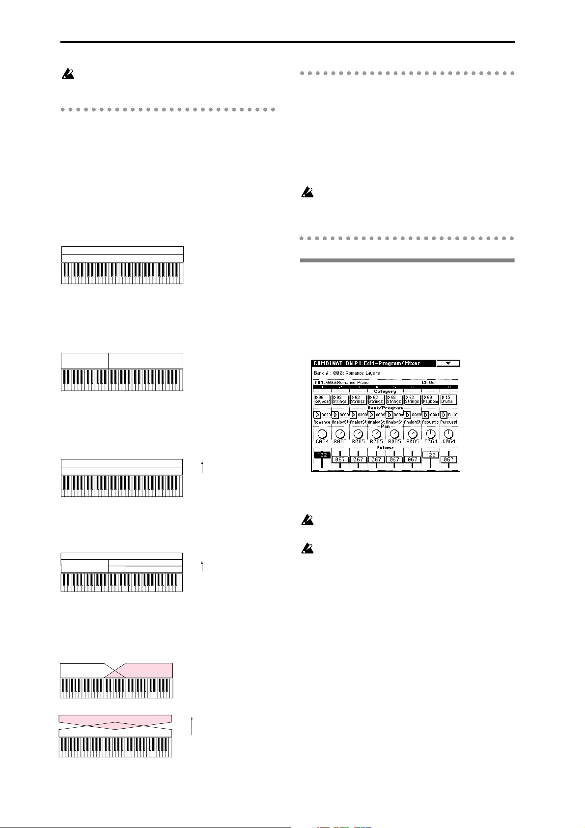
If you wish to keep a combination that you edited,
you must Write it (
☞p.38).
Layer, split, and velocity switch
Within a combination, you can use keyboard location
and velocity to change the program that sounds. The
programs assigned to each timbre can sound in three
ways: as a layer, a split, or a velocity switch. A combi-
nation can be set to use any one of these methods, or to
use two or more of these methods.
Layer
Layer refers to settings which cause two or more programs to sound simultaneously when a note is played.
Program A
Program B
Layer:
Two or more programs sound
simultaneously.
Split
Split refers to settings which cause different programs
to sound depending on the keyboard location that is
played.
Program A
Program B
Split:
Different programs will sound in
different areas of the keyboard.
The Compare function
When P1–P9 are displayed, you can press the [COMPARE] key to make the LED light. This will recall the
combination that had been written before you began
editing. When you press the [COMPARE] key once
again the LED will go dark, and you will return to the
sound that you had been editing. Use this when you
wish to compare the edited sound with the un-edited
sound.
If you continue editing when the [COMPARE] key
LED is lit, the LED will go dark, and the current
sound will now be the sound that is recalled when
the [COMPARE] key LED is dark.
P1: Edit-Program/Mixer
Timbre 1–8 program, pan and volume
Here you select a program for each timbre 1–8, and set
its pan and volume. These are the same parameters as
in P0: Play, and can be edited from either page.
Velocity switch
Velocity Switch refers to settings which cause different
programs to sound depending on the velocity (keyboard playing dynamics).
Program B
Program A
On the TRITON, you can use a different program for
each of up to eight timbres, and combine two or more
of the above methods to create even more complex setups.
Program A
Program B
Program D
Program C
As an additional possibility, you can set the slope for a
key zone or velocity zone so that the volume diminishes gradually. This lets you change a split into a key-
board crossfade, or a velocity switch into a velocity
crossfade.
Program A
Program B
Program A
Program B
Strong
Keyboard playing dynamics
Soft
Velocity Switch:
Keyboard playing dynamics
(velocity) switches between
different programs.
Strong
Keyboard playing dynamics
Soft
Example:
B and C/D are split. In the lower
keyboard range, A and B are
layered. In the higher keyboard
range, C and D are switched by
velocity and layered with A.
Keyboard X-Fade (keyboard crossfade):
As you play from low notes to high notes,
the volume of A will fade out, and the
volume of B will fade in.
Strong
Keyboard playing dynamics
Soft
Velocity X-Fade (velocity crossfade):
As you play with increasingly stronger
velocity, the volume of A will fade out, and
the volume of B will fade in.
Category, Bank/Program
Select the program for each timbre.
Selection of programs via MIDI program change is
disabled in this page.
If a program currently being edited in Program
mode is used in a combination, the combination
will use the sound that is being edited.
Pan
Specify the panning (stereo location) for each timbre. A
setting of C064 will reproduce the oscillator pan setting
of the program. Moving this to left or right will move
the sound to left or right while preserving the pan relationship between the oscillators. A setting of L000 is far
left, and R127 is far right. (
☞p.31 in the Parameter
Guide.)
Volume
Adjust the volume of each timbre 1–8.
Create the overall sound by adjusting the volume balance between timbres. The “Volume” setting is an
important aspect of creating the sound, and this setting
will have a significant effect on the overall impression
produced by the combination.
54
Page 59
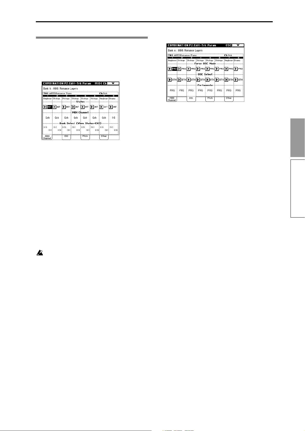
P2: Edit-Trk Param
Settings for status, MIDI channel,
and playing mode
MIDI Channel tab
Status
Select a “Status” of INT for all timbres that you wish to
use. Select Off for unused timbres.
Timbres that are set to INT will sound the TRITON’s
internal tone generator. Timbres set to Off, EXT, or EX2
will not sound. Timbres set to EXT or EX2 can control
an external tone generator connected via MIDI.
OSC tab
Force OSC Mode
Normally you will set this to PRG.
If you wish to force a polyphonic program to sound
monophonically, set this either to MN (Mono) or LGT
(Legato). Conversely, set this to Poly if you wish to
force a monophonic program to play polyphonically
(
☞p.33 in the Parameter Guide).
OSC Select
Normally you will set this to BTH (Both).
If the timbre is using a program whose “OSC Mode” is
Double, and you want only OSC1 or OSC2 (not both)
to sound, set this to OS1 (only OSC1 will sound) or
OS2 (only OSC2 will sound).
Basic functions
MIDI Channel
Timbres that you wish to play from the TRITON’s keyboard must be set to the global MIDI channel. Your
playing on the keyboard is transmitted on the global
MIDI channel, and will sound any timbre that matches
this channel. Normally you will set this to Gch. When
this is set to Gch, the MIDI channel of the timbre will
always match the global MIDI channel, even if you
change the global MIDI channel.
On some preset combinations that use the arpeggiator, timbres assigned to the arpeggiator may
not have a “Status” of INT and “MIDI Channel” of
Gch.
The reason for this is that these settings are for timbres that sound only when the arpeggiator is on.
This is a very useful technique for creating combinations that use the arpeggiator. Refer to “Dual
arpeggiator editing” (
(
☞p.39) in the Parameter Guide, and study the rela-
tionship between arpeggiator assignments, “Status,” and “MIDI Channel.”
☞p.104) and to “7–1b”
Bank Select (when Status = EX2)
This setting is valid when “Status” is set to EX2. It
specifies the Bank Select message that will be transmitted from the TRITON.
Portamento
Normally you will set this to PRG.
If you want the portamento setting specified for the
program of the timbre to be forced off, set this parameter to Off. Conversely, if you want to forcibly turn the
portamento on, or to change the portamento time, set
this to a value of 001–127 to specify the portamento
time.
Pitch tab
Transpose, Detune
These parameters adjust the pitch of the timbre.
• In a layer-type combination, you can set two or
more timbres to the same program, and create a
richer sound by using “Transpose” to shift their
pitch apart by an octave or by using “Detune” to
create a slight difference in pitch between the two.
• In a split-type combination, you can use
“Transpose” to change the pitch of the program in
each key zone in steps of an octave.
• If you wish to change the playback pitch of a drum
program, use “Detune.” If you change the
“Transpose” setting, the correspondence between
notes and drum sounds will change.
Combination mode
55
Page 60

Other tab
Delay [ms]
Specify the timing of the delay before each timbre
sounds.
Select the preset combination A127: One Fin-
gerTVShow, and play a single note. Timbres will
sound consecutively, according to their Delay setting.
If you select KeyOff for this parameter, the timbre will
sound when the note is released.
P3: Edit-MIDI Filter
MIDI filter settings
For each MIDI Filter item, you can specify whether or
not the corresponding MIDI message will be transmitted and received. The checked items will be transmit-
ted and received.
Key Zone tab (key zone settings)
For each timbre, you can specify the range of notes for
which it will sound. Each area that sounds a timbre is
referred to as a Key Zone. By setting key zones, you
can create a combination in which different programs
sound in different areas of the keyboard.
By combining key zones specified for each timbre, you
can create layered or split combinations.
The upper and lower limits for the key zone of each
timbre are set by the “Top Key” and “Bottom Key”
respectively. For example in the following diagram,
timbres 1–3 are set to create a layered and split combination. This is specified by the key zone settings.
Timbres 2 and 3 create a layer. Timbre 1 and timbres 2/
3 are split between the B3 and C4 note numbers.
Timbre 3
Timbre 2
1 To create a combination like the one shown above,
first use the P0: Play or P1: Edit-program/Mixer
page to select a program for each timbre 1–3.
Select a piano program for timbre 1.
Select a brass program for timbre 2.
Select a strings program for timbre 3.
Strings
Brass
C–1 C4 G9B3
PianoTimbre 1
For example, suppose that you have a split combination in which timbre 1 uses a bass program and timbre
2 uses a piano program.
You could uncheck “Enable Damper” for timbre 1, and
check “Enable Damper” for timbre 2.
With these settings, pressing a damper pedal connected to the [DAMPER] jack would apply the damper
effect only to the piano program of timbre 2.
For details on each MIDI filter item, refer to p.35 in the
Parameter Guide.
The MIDI Filter settings do not switch the corresponding function on/off, but merely specify
whether or not that MIDI message is transmitted
and received. For example if portamento is on,
portamento will be applied to the sound of the
TRITON even if the “Enable Portamento SW” is
unchecked.
P4: Edit-Zone/Ctrl
Layer, split, and velocity switch settings
You can make most of the settings necessary for creating layers, splits, velocity switches, keyboard crossfades, and velocity crossfades.
2 In P2: Edit-Trk Param, select the MIDI Channel
tab. Set each timbre you wish to use to a “Status”
of INT, and a “MIDI Channel” of Gch or the global
MIDI channel. (“G” will be displayed following
the channel number.)
3 In P4: Edit-Zone/Ctrl Key Zone tab, set the “Top
Key” and “Bottom Key.”
Set timbre 1 to a “Top Key” of G9 and a “Bottom
Key” of C4. Set timbres 2 and 3 to a “Top Key” of B3
and a “Bottom Key” of C–1.
You can also input the value by holding down the
[ENTER] key and playing a note.
As an option, you could specify the range velocities,
so that a portion of timbre 1 overlapped with timbres 2 and 3 (creating a layer), and setting “Top
Slope” and “Bottom Slope” so that the volume
would change gradually between B3 and B4. This
would avoid an abrupt change in sound between
the two keyboard areas.
56
Page 61
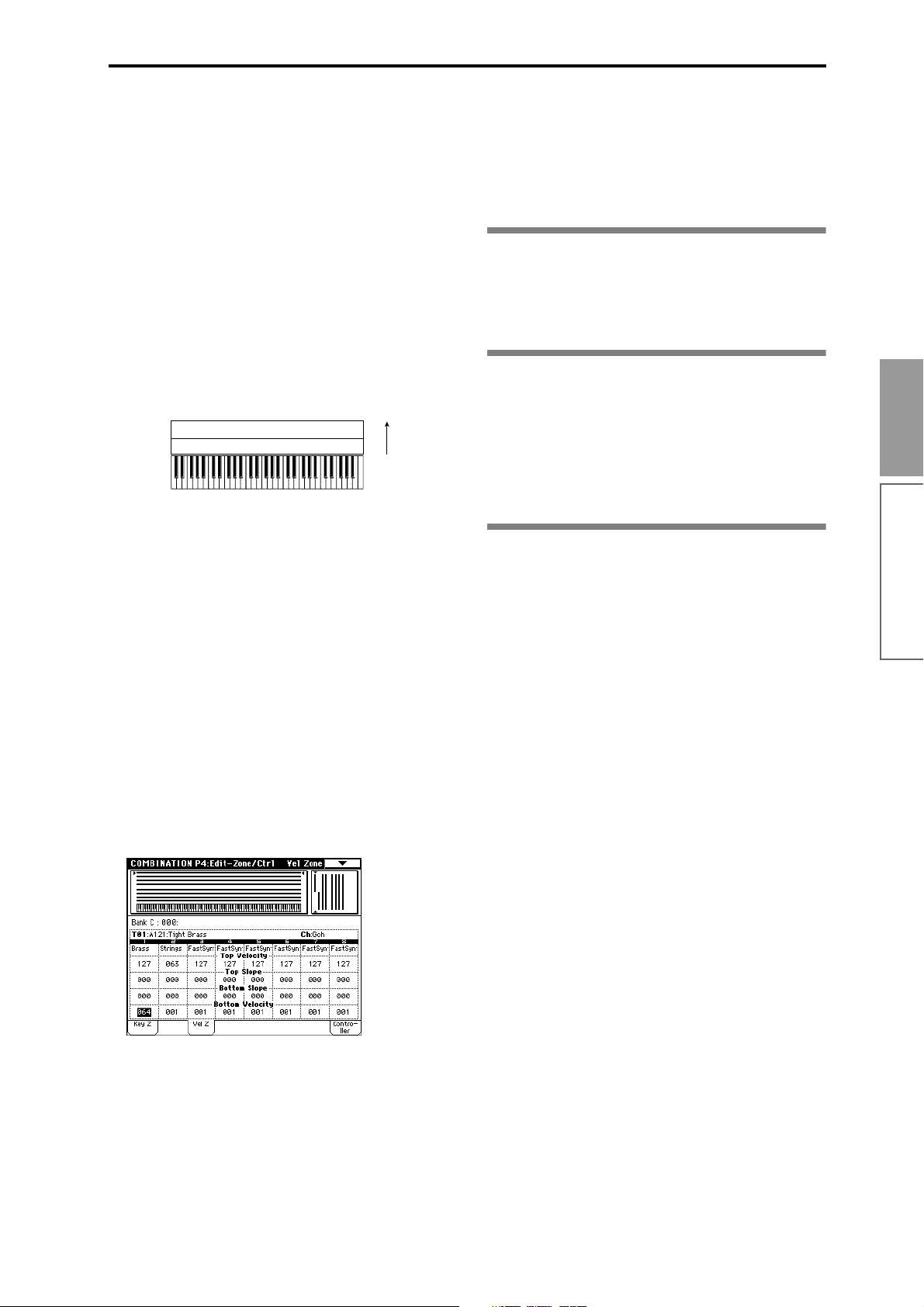
Vel (Velocity) Zone tab (Velocity zone settings)
For each timbre, you can specify a range of velocities
for which it will sound. The range of velocities for
which a timbre will sound is called the Velocity Zone.
By setting a velocity zone, you can set up a timbre
which will be sounded only by notes played at a certain strength, and not by stronger or weaker notes.
By combining timbres that have differing velocity zone
settings, you can create velocity switched combina-
tions.
The upper and lower limits of the velocity zone of each
timbre are determined by the “Top Velocity” and “Bottom Velocity” respectively. The following diagram
shows an example of a velocity switched combination
in velocity will switch between timbres 1 and 2 to play
different programs. Such combinations are created by
setting the velocity zone.
Timbre 1
Timbre 2
1 To create a combination such as shown above, first
use P0: Play or P1: Edit-program/Mixer to select the
program that each timbre 1 and 2 will use.
Select a brass program for timbre 1.
Select a strings program for timbre 2.
Brass
Strings
127
64
63
1
Velocity switch
Controller Setup tab
For each combination, you can specify the functions of
the [SW1] and [SW2] keys, and the B-mode functions
of REALTIME CONTROLS knobs [1]–[4] (
(
☞p.38, 217, 218 in the Parameter Guide)
☞p.127).
P7: Edit-Arpeggiator
Arpeggiator settings
Make settings for the arpeggiator (☞p.98).
P8: Edit-Insert Effect
Insert Effect settings
Select insert effects, and make settings for them. Here
you can also set the oscillator routing (send levels to
the insert effects, master effects, and individual outputs) (
☞p.108).
P9: Edit Master Effect
Master Effect settings
Basic functions
2 In P2: Edit-Trk Param, select the MIDI Channel
tab. Set each timbre you are using to a “Status” of
INT, and a “MIDI Channel” of Gch or the global
MIDI channel. (“G” will be displayed after the
channel number.)
3 In P4: Edit-Zone/Ctrl Vel Zone tab, set the “Top
Velocity” and “Bottom Velocity.”
Set timbre 1 to a “Top Velocity” of 127 and a “Bot-
tom Velocity” of 64.
Set timbre 2 to a “Top Velocity” of 63 and a “Bottom
Velocity” of 1.
You can also input the value by holding down the
[ENTER] key and playing a note on the keyboard.
Select master effects, and make settings for them. Here
you can also make master EQ settings (
☞p.108).
Combination mode
As an option, you could specify the range velocities,
so that a portion of the two timbres overlapped, and
set “Top Slope” and “Bottom Slope” so that the volume would change gradually within that area. This
would avoid an abrupt change in sound between
velocities 63 and 64.
57
Page 62

Sequencer mode
The TRITON contains a 16-track MIDI sequencer.
This sequencer is the center to which the TRITON’s
numerous functions are integrated, allowing it to be
used in a variety of situations including music production and live performance.
When you turn off the power, the settings made in
Sequencer mode and the song data, cue list data,
and user pattern data that you recorded are not
backed up. If you wish to keep this data, you must
save it on a floppy disk or external SCSI device (if
the separately sold EXB-SCSI option is installed)
before turning off the power, or perform a MIDI
data dump to save the data on an external data
filer etc.
If you wish to save the programs, track parameters
and effects etc. selected for a song as a template
song, use the page menu command “Save as User
Template Song.”
Immediately after the power is turned on, the TRITON will not contain any cue list data or song
data, so if you wish to playback a song on the
sequencer, you must first load data from floppy
disk or receive a MIDI data dump from an external
MIDI sequencer (
eter Guide)
☞p.40, 92). (☞p.119 in the Param-
Features of the sequencer
• The sequencer lets you record a maximum of
200,000 events (note data etc.), up to 200 songs,
and as many as 999 measures per song.
• Up to 20 cue lists can be created.
A cue list is an arrangement of up to 99 songs that
will be played as a chain. You can specify the number of times that each song will repeat. Songs in a
cue list can also be converted into a single song.
• The RPPR (Realtime Pattern Play/Recording)
function can be used for playback or recording.
• The dual polyphonic arpeggiator can be used for
playback or recording.
• Sixteen different template songs are built-in, and
contain program and effect settings suitable for
various musical styles. Up to sixteen original
templates that you create can be registered as user
template songs.
• Five stereo insertion effects, two master effects,
and a stereo master EQ can be used for each song.
• Sample waveforms that you sampled in Sampling
mode or loaded in Disk mode can be converted
into programs and used in a song.
• If the separately sold EXB-MOSS option is
installed, MOSS tone generator programs can be
played multi-timbrally. (For example, you could
use two bass voices and four electric piano voices.
However, effect settings cannot be made
separately.)
• Timing resolution is a maximum of /192.
• Sixteen tracks are provided for musical data, and a
master track contains time signature and tempo
data that controls the playback.
•A track play loop function lets you loop specified
measures independently for each track.
• 150 preset patterns ideal for drum tracks are built
in. In addition, you can create up to 100 user
patterns for each song. These patterns can be used
as musical data within a song, or can be played by
the RPPR function.
• Various methods of recording are supported,
including realtime recording in which your
performance on the keyboard and controllers
(including MIDI control events) is recorded just as
you play, and step recording in which the timing,
length, and velocity of each note can be specify in
the LCD as you input the pitches from the
keyboard.
• The musical data and control events that you
recorded can be edited in various ways (including
event editing and many other edit commands).
• When the “Status” of a track is set to INT or BTH,
an external sequencer can be used to play the
TRITON as a multi-timbral tone generator.
When the “Status” of a track is set to BTH, EXT, or
EXT2, the sequencer of the TRITON can play exter-
nal tone generators.
• Playback can be synchronized with an external
MIDI device.
• The TRITON’s AMS (Alternate Modulation)
capability lets you use control changes for realtime
control of the parameters of the programs used in a
program. Its MIDI Sync. functionality lets you
synchronize the LFO speed to changes in the
tempo.
• Dmod (Dynamic Modulation) functionality lets
you control effect parameters in realtime. You can
also use MIDI Sync. to synchronize the LFO speed
or delay time to changes in the tempo.
• You can assign names not only to the song, but
also to each pattern and track.
• Combination settings can be copied to a song.
• Sequencer data such as a song or cue list that you
create can be saved in the TRITON’s native format,
or transmitted as a MIDI data dump.
• Programs or sample files can be linked and saved
on external media. This data can be loaded when
desired.
• A song you created can be converted into SMF
(Standard MIDI File) data and saved on external
media. SMF songs can also be loaded.
• The PLAY/MUTE/REC buttons and SOLO
buttons let you instantly play/mute any desired
track.
• You can rewind or fast-forward while listening to
the sound.
• The [LOCATE] key lets you move quickly to a
desired location.
58
Page 63

• The Track BPM Adjust function (playback pitch
adjust) can automatically change the pitch of a
sample/multisample that was sampled in
Sampling mode or loaded in Disk mode so that it
matches the tempo.
About song data
The following two types of song data can be loaded
from floppy disk or other external media into the TRITON’s sequencer.
• Song data saved in the TRITON’s own format
This data cannot be loaded by another device, but
the playback will faithfully reproduce the detailed
settings unique to the TRITON. We recommend that
song data intended for playback on the TRITON be
saved in this format.
• Standard MIDI Files
This format is not able to provide a totally faithful
reproduction of the performance on the TRITON in
the way that the TRITON’s own format does
(although there will be no problem for normal playback), but does provide compatibility with other
SMF-compatible devices.
To load song data from floppy disk or save song data
to floppy disk, use Disk mode. (
☞p.40, p.92)
Memory Protect
Before you record a track or pattern, or edit the musical
data, you will need to turn off the memory protect setting in Global mode. (
☞p.37)
The Compare function
When you perform realtime recording, step recording,
or track editing, this function allows you make beforeand-after comparisons. (
☞p.14)
In general, track and pattern event data can not be
returned to its original state.
Comparing song parameters is possible only during
song editing (when executing a page menu command).
Operations for which Compare is not available
• Editing song parameters
(Including “Track Name” and “Pattern Name”)
• Page menu commands other than those listed
above (in Operations for which Compare is
available)
About MIDI
Synchronizing the sequencer with an external MIDI
device
The record/playback tempo of the TRITON’s
sequencer can be synchronized to an external MIDI
device such as a sequencer or rhythm machine
(
☞p.122).
Track status settings in Sequencer mode
You can make settings for the TRITON’s sequencer to
specify whether it will sound the internal tone generator or an external tone generator.
When Track Status is set to INT, operating the TRI-
TON’s keyboard and controllers will sound and control the TRITON’s own tone generator.
When Track Status is set to EXT, EX2 or BTH, operat-
ing the TRITON’s keyboard and controllers will sound
and control the external tone generator. (The MIDI
channel of the external tone generator must match the
“MIDI Channel” of the track that is set to EXT, EX2 or
BTH.) With a setting of BTH, both the external tone
generator and the TRITON’s tone generator will sound
and be controlled.
Basic functions
Sequencer mode
If you continue editing when the [COMPARE] key
LED is lit, the LED will go dark. That musical data
will now be the data that is selected when the
[COMPARE] key LED is dark.
Operations for which Compare is available
• Recording to a track
• Track Edit
All commands other than P5: Page menu commands “Memory Status,” “FF/REW Speed,” and
“Set Location”
• Recording to a pattern
• Pattern Edit
All commands other than P6: Page menu commands “Memory Status” and “FF/REW Speed”
• Song Edit
P: 0, 2, 3, 4, 7: Page menu commands “Delete Song”
and “Copy From Song”
P1: Page menu commands “Convert to Song” and
“Copy Song”
If you wish to use the TRITON’s Sequencer mode as a
16-timbre (16-track) tone generator, set each track to
either INT or BTH (
☞p.55 in the Parameter Guide).
59
Page 64

About each page in Sequencer
The structure of Sequencer mode
mode
● For details on how to access each page or modes,
refer to “Basic operation of the TRITON” (
P0: Play/REC Play and record songs, and make related
settings. Select the program for each track,
and set pan and level.
P1: Cue List Play, create, and make settings for cue
lists.
P2: Trk Param Parameter settings for each track of a
song. MIDI, OSC, Pitch, etc.
P3: MIDI Filter MIDI message transmission/reception filter
settings for each track of a song.
P4: Zone/Ctrl Key Zone and Velocity Zone settings for
each track of a song. Controller settings. If
the separately sold EXB-MOSS expansion
is installed, settings for related parameters.
P5: Track Edit Edit musical data for song tracks. Specify
track names.
P6: Pattern/RPPR Record and edit patterns for a song. Spec-
ify pattern names. RPPR function settings
for a song.
P7: Arpeggiator Arpeggiator settings.
P8: Insert Effect Select and make settings for insert effects.
Set the routing, insert effects, master
effects, and individual output send
amounts for each track of the song.
P9: Master Effect Select and make settings for the master
effects. Master EQ settings.
If the separately sold EXB-MOSS option is
installed, bank F programs can also be used in
Sequencer mode. For details on the parameters of
bank F programs, refer to the EXB-MOSS owner’s
manual.
☞p.12).
Sequencer mode consists of the following pages.
Songs
A song consists of tracks 1–16, a master track, song
parameters such as the song name, effect, arpeggiator
and RPPR parameters, and 100 user patterns.
A maximum of 200 such songs can be created on the
TRITON.
Tracks 1–16 and the master track each consist of setup
parameters located at the start location, and musical
data within the track.
Setup parameters Musical data
Tracks 1–16 Tracks 1–16
Bank/Program No. * Note On/Off
PLAY/MUTE/REC Program Change
(including Bank Select)
Pan * Pitch Bend
Volume * After Touch (Poly After)
Track Play Loop Control Change
Loop Start Measure Pattern No.
Loop End Measure
Status
MIDI Channel
Bank Select
(When Status=EX2)
Force OSC Mode
OSC Select
Portamento *
Transpose **
Detune **
Bend Range **
Delay
Use Program's Scale
MIDI Filter
Key Zone
Velocity Zone
Track Name
Arpeggiator Assign
IFX/Indiv.Out BUS Select
Send1(MFX1) *
Send2(MFX2) *
60
Master track
Time signature *
Tempo *
* When you change the setting during realtime-
recording, this will be recorded as musical data.
This allows the starting settings to be modified during the playback.
Page 65

** Musical data (MIDI RPN data) can be used to
change the starting settings during playback.
For details on control changes, refer to p.223 in the
Parameter Guide.
Patterns
There are two types of patterns: preset patterns and
user patterns.
• Preset patterns: Patterns suitable for drum tracks
are preset in internal memory, and can be selected
for any song.
• User patterns: Each song can have up to 100
patterns. When using a pattern in a different song,
use the page menu commands “Copy Pattern” or
“Copy From Song” etc. to copy the pattern. The
pattern length can be specified in units of a
measure.
Each pattern consists of musical data for one track. It is
not possible to create patterns that contain multiple
tracks.
These patterns can be used as track musical data by
being placed in a track (page menu command “Put to
Track”) or copied to a track (page menu command
“Copy to Track”). Alternatively, you can use a pattern
with the RPPR function of a song.
As track musical data of a song
Phrases that are used repeatedly in a song can be
recorded as patterns.
When you place (“Put to Track”) such a pattern in a
song, the musical data of that pattern will be recalled
and played when playback reaches the measure in
which the pattern was played. When using a phrase or
rhythm that occurs repeatedly, you can make more efficient use of memory by creating a pattern and placing
it in multiple locations of the song, rather than actually
recording the same data directly to each location of the
song. However, be aware that if you modify the pattern itself, the playback will be affected for all measures at which the pattern had been placed.
If you copy (“Copy to Track”) a pattern to a track of the
song, the playback data will be recorded on the track
just as if you had recorded it onto the track in the first
place. This will occupy more memory than if you use
“Put to Track,” but you will be able to edit each location of data independently without affecting other
locations, just as when editing normal track data.
The RPPR (Realtime Pattern Play/Recording)
function:
For each song, you can assign patterns to each note of
the keyboard, and play notes on the keyboard to playback or record patterns in realtime.
Cue List
A cue list allows you to playback multiple songs in
succession. The TRITON allows you to create 20 cue
lists. Each cue list allows you to connect a maximum of
99 songs in any order, and to specify the number of
times that each song will repeat.
Each unit in a cue list is called a “step,” and each step
contains a song number and the number of repeats.
For example, a song consisting of an introduction, melody A, melody B, bridge, solo backing, and ending
could be created using a separate song for each unit.
Then you could use a cue list to play the introduction
twice, melody A four times, melody B four times, the
break twice, melody A four times, ... etc. to create the
completed song. When you will need to change the
structure of the song, the cue list function provides an
efficient way to do so.
The page menu command “Convert to Song” lets you
convert the two or more songs in a cue list into a single
song. This allows you to use a cue list to create the
backing, then convert the cue list into a song and add
solo phrases on unused tracks.
Basic functions
Sequencer mode
Track 1
Track 2
Track 3
Track 4
Track 5
Track 6
Track 7
Track 8
Track 16
Master Track
Setup parameters
Setup parameters
Setup parameters
Setup parameters
Setup parameters
Setup parameters
Setup parameters
Setup parameters
Setup parameters
Tempo, time signature data
Musical data
Musical data
Musical data
Musical data
Musical data
Musical data
Musical data
Musical data
Musical data
Routing : P8-1
Track
Insert Effect
Master Effect
Individual Outputs
Insert Effect 1 ... 5 : P8
Master Effect 1, 2 : P9
Pattern U00 ... U99
RPPR Setup
: P6
MasterEQ : P9
Controller Setup : P4- 4
Arpeggiator : P7
AUDIO OUTPUT
L/MONO, R
AUDIO OUTPUT
INDIVIDUAL 1,2,3,4
61
Page 66

Playback
the “mute” function allows you to silence a specified track.
Playing a song (Play)
When you wish to playback song data on the
sequencer, you must first record song data, or load or
dump song data into the TRITON.
To load song data from a floppy disk etc., use Disk
mode.
1 In Sequencer mode, press P0: Play/REC.
2 Use “Song No. and name” to select the desired
song (
☞p.64).
3 Press the [START/STOP] key.
The song you selected in step 2 will begin playing.
Pressing the [START/STOP] key in pages other
than Sequencer mode P1: Cue List or P5: Pattern/
RPPR will start song playback. When the [START/
STOP] key is pressed in P1: Cue List, the currently
selected cue list will begin playing. When the
[START/STOP] key is pressed in P5: Pattern/
RPPR, the currently selected pattern will begin
playing.
4 If you press the [START/STOP] key during play-
back, the playback will stop.
Press the [START/STOP] key once again, and playback will resume from where it had been stopped.
• Pressing the [LOCATE] key will move to the
specified location.
• Pressing the [PAUSE] key will resume playback.
• Pressing the [<<REW], [FF>>] keys will rewind or
fast-forward. These can be used during playback
or when paused.
The speed of rewind and fast-forward is set by the
“FF/REW Speed” page menu command.
Mute/Solo function
You can use the PLAY/MUTE/REC buttons and SOLO
ON/OFF buttons in the Program Select tab of P0: Play/
REC to hear or mute a desired individual track 1–16.
For example, this can be used when you wish to record
new tracks while listening only to the rhythm section
of the previously recorded tracks.
You can use the page menu command “Solo Selected
Track” to hear only the currently selected tracks. It is
convenient to use this while setting track parameters
or effect settings (
Make sure that page P0: Play/Rec is opened.
1 Press the [START/STOP] key to playback the song.
2 Press the Prog. 1–8 tab.
☞p.47 in the Parameter Guide).
Press the track 2 PLAY/MUTE/REC button once.
The display will change, and the playback of track 2
will also be muted.
To cancel muting, press the PLAY/MUTE/REC but-
ton once again so that the display changes to PLAY.
Each time you press the button, the display will
alternate between MUTE and PLAY.
4 Next press the track 1 SOLO button once.
The display will change, and now only the track 1
playback will be heard. In this way, the Solo function lets you hear only a specified track. (If both
Mute and Solo are used, the Solo function will be
given priority.)
Press the track 2 SOLO button once.
The display will change, and only the playback of
tracks 1 and 2 will be heard.
To turn off the Solo function, press the SOLO button once again. Press the track 1 and 2 SOLO buttons once each.
The display will change, and the playback of tracks
1 and 2 will be muted. If the Solo function is turned
off for all tracks, playback will be according to the
PLAY/MUTE/REC button settings.
[LOCATE] settings
These settings are made by the page menu command
“Set Location.” You can also set the location during
playback by holding down the [ENTER] key and pressing the [LOCATE] key (
Normally you will set this to 001:01.000. You will
return to the beginning of the song.
When you select a song, the [LOCATE] setting will
automatically be set to 001:01.000.
☞p.48 in the Parameter Guide).
Other playback
In Sequencer mode, you can also use playback functions such as Loop All Tracks, play Patterns (using the
RPPR function), Track Play Loop, and Cue List.
3 Press the track 1 PLAY/MUTE/REC button once.
The display will change to “MUTE,” and the playback of track 1 will no longer be heard. In this way,
62
Page 67

Recording
The process by which your playing on the TRITON’s
keyboard and controllers is captured on the tracks or
patterns of a song as data is called “recording.”
Recording on a track, and recording on a pattern
Recording on a track
There are two ways to record on a track: realtime
recording and step recording. You can choose from a
further six types of realtime recording.
In addition, you can use event editing to modify data
that has been recorded or to insert data, and use track
editing operations such as Create Control Data to
insert data such as bend, after touch, and control
changes.
• Overdub
With this method, the newly recorded musical data
is added to the existing data.
When you perform overdub recording on a previously-recorded track, the newly recorded data will
be added to the previously-recorded data.
It is best to select this method when you wish to add
control data, or to record tempo data onto the master track. This lets you record data without erasing
the existing data.
• Manual punch-in
With this method, the musical data previously on
the track is overwritten by the newly recorded data.
While the song is playing, you can press the [REC]
key or a connected pedal switch at the desired location to start or stop recording.
• Auto punch-in
With this method, the musical data previously on
the track is overwritten by the newly recorded data.
First you must specify the area that will be rerecorded. Then playback the song, and recording
will occur automatically at the specified area.
Basic functions
Recording on a pattern
There are two ways to record on a pattern: realtime
recording and step recording. For realtime recording,
only one recording type (loop) is available.
In addition, you can use event edit operations to modify data that has been recorded or to insert data.
The page menu command “Get From Track” can be
used to take musical data from a desired area of a
track, and use it as the musical data for a pattern. Conversely, the page menu commands “Put to Track” and
“Copy to Track” can be used to place or to copy the
musical data of a pattern in a track.
Realtime recording
This is a method of recording in which your playing on
the keyboard and your operations of controllers such
as the joystick are recorded in realtime.
This method of recording is normally used one track at
a time, and is called single track recording.
As an alternative, multitrack recording allows you to
simultaneously record multiple channels of data onto
multiple tracks. This is the method you will use when
using the RPPR function to record multiple tracks of
musical data at once, or when you playback existing
sequence data on an external sequencer and record it
onto the TRITON’s sequencer in realtime (
p.73).
• Overwrite
With this method, the musical data previously on
the track is overwritten by the newly recorded data.
When you perform overwrite recording on a previously-recorded track, its musical data will be
replaced by the newly recorded data.
Normally you will use this method to record, and
then modify the results by using other types of realtime recording or event editing.
☞p.64, p.66,
• Loop All Tracks
This method lets you continue recording as you add
musical data.
Recording will occur repeatedly over the specified
area.
• Multi
Multitrack recording allows you to simultaneously
record onto multiple tracks, each with a different
channel. This method can be used with overwrite,
overdub, manual punch-in, and auto punch-in
recording.
Step recording
This is a method of recording where you specify the
note timing, note length, and velocity etc. in the LCD
screen, and use the keyboard to input the pitches.
Only note-on/off data can be recorded with this
method.
Event Edit and Create Control Data
Note data is the only type of data that can be recorded
in step recording. However as ways to record other
types of data outside of realtime, you can use the Event
Edit and Create Control Data functions.
Event Edit is intended as a way to edit previouslyrecorded data, but you can also use it to modify program numbers or insert control changes.
Create Control Data is a function that lets you create
and insert controller data that changes smoothly
between two specified values over the specified length
of time. This is used to input bend, after touch, and
control change data etc.
Sequencer mode
63
Page 68

Realtime recording on a track
Preparations for recording
Before you begin recording, you need to make track
settings.
Be sure to turn off the Global mode protect setting
(
☞p.37).
Song No.
and name
Track Select
5 Press the [REC/WRITE] key.
The TRITON will enter record-standby mode.
The PLAY/MUTE/REC button of the track(s) you
specified in step 3 will change from PLAY to REC.
The metronome will begin sounding. If it does not,
use the Preference tab “Metronome Setup” to make
metronome settings. The default values are
“Sound” Only REC, “BUS Select” L/R, “Level” 127,
and “Precount” 2. With these settings, there will be
a two-measure pre-count, the metronome sound
will be output at the maximum level from the L/
MONO and R jacks (and from the headphones), and
will be heard only during recording.
Category
Bank/Program
1 In Sequencer mode, select P0: Play/REC, and select
the Program T01–08 tab (or Program T09–16 tab).
2 Press “Song No. and name,” and select the song
that you wish to record.
Use numeric keys [0]–[9] to enter the song number,
and press the [ENTER] key. If you press the popup
button, you can select from the popup menu.
If you select a song number that has not yet been
recorded, the Create New Song dialog box will
appear. Press the OK button.
To set the song name, use the page menu command
“Rename Song.” (
☞p.38 “Assigning a name
(Rename)”).
3 Use “Track Select” to select the track that you wish
to record.
4 Use “Bank/Program” or “Category” to select the
program for the track you wish to record.
6 Set “Tempo Mode” to Manu (manual), and as you
listen to the metronome, use “ =” to set the tempo.
7 Set “Meter” to the desired time signature.
8 If necessary, set “Reso” (resolution) to the desired
realtime quantize setting (
☞p.68).
This completes preparations for recording. The
recording procedure will depend on the “Overwrite” – “Multi (multitrack recording)” setting
explained below. Press the [REC/WRITE] key to
temporarily cancel record-standby mode, and try
out the various recording methods described below.
The time signature will be recorded when you
actually begin recording. If you cancel recording
during recording-standby or during the precount,
the time signature specified in 7 will not be
recorded.
Overwrite
Use this method when recording for the first time.
1 Make the necessary settings in “Preparations for
recording.”
2 In the Preferences tab “Recording Setup,” select
Over Write.
Use the Prog.1–8 tab to select a program for tracks
1–8, and the Prog.9–16 tab to select a program for
tracks 9–16.
You may find it convenient to use the page menu
command “Load Template Song” and use the settings from a template song (
☞p.67).
If necessary, select the Mixer tab and set the pan and
volume. The status and MIDI channel of each track
are set by P2: Trk Param MIDI Ch tab “Status” and
“MIDI Channel.”
It is a good idea to set tracks 1–16 to “MIDI Channel” 1–16 respectively. (This is the default.) Tracks
that are set to the same MIDI channel will sound
simultaneously when either track is recorded or
played.
Make sure that “Status” is INT or BTH.
64
Location
3 In “Location,” specify the location at which you
wish to begin recording.
If no musical data has been recorded it will not be
possible to change the location, so proceed to step
4.
Page 69

4 Press the [REC/WRITE] key, and then press the
[START/STOP] key.
If “Metronome Setup” has the default settings (refer
to “Preparations for recording” step 5), the metro-
nome will sound for a two-measure pre-count, and
then recording will begin. Play the keyboard and
move controllers such as the joystick to record your
performance.
5 When you finish playing, press the [START/STOP]
key.
Recording will end, and the location will return to
the point at which you begin recording.
At this time if you press the [PAUSE] key instead of
the [START/STOP] key, recording will pause. When
you press the [PAUSE] once again, recording will
resume. When you are finished, press the [START/
STOP] key to stop recording.
Overdub
1 Make the necessary settings in “Preparations for
recording.”
2 In the Preferences tab “Recording Setup,” select
Over Dub.
P2: Controller “Foot Switch Assign” to Song Punch
In/Out (
7 Press the [START/STOP] key.
Playback will stop, and you will return to the location that you specified in step 3.
☞p.125).
Auto punch-in
1 Make the necessary settings in “Preparations for
recording.”
2 In the Preferences tab “Recording Setup,” select
Auto Punch In.
3 In “M__–M__” specify the area that you wish to
record.
For example if you specify M005–M008, recording
will occur only from measure 5 to measure 8.
4 In “Location,” specify a location several measures
earlier than the point at which you wish to begin
recording.
5 Press the [REC/WRITE] key, and then press the
[START/STOP] key.
Basic functions
3 For the rest of the procedure, refer to steps 3–5 of
“Overwrite” (
☞p.64).
Manual punch-in
1 Make the necessary settings in “Preparations for
recording.”
2 In the Preferences tab “Recording Setup,” select
Manual Punch In.
3 In “Location,” specify a location several measures
earlier than the point at which you wish to begin
recording.
4 Press the [START/STOP] key.
Playback will begin.
5 At the point at which you wish to begin recording,
press the [REC/WRITE] key.
Recording will begin. Play the keyboard and operate controllers such as the joystick to record your
performance.
6 When you finish recording, press the [REC/
WRITE] key.
Recording will end (playback will continue).
Instead of pressing the [REC/WRITE] switch in
steps 5 and 6, you can use a foot switch connected
to the [ASSIGNABLE SWITCH] jack. Set the Global
Playback will begin.
When you reach the starting location you specified
in step 4, recording will begin. Play the keyboard
and operate controllers such as the joystick to record
your performance. When you reach the ending location you specified in step 4, recording will end.
(Playback will continue.)
6 Press the [START/STOP] key.
Playback will stop, and you will return to the location you specified in step 4.
Loop All Tracks
1 Make the necessary settings in “Preparations for
recording.”
2 In the Preferences tab “Recording Setup,” select
Loop All Tracks.
However since multitrack recording is not possible,
the “MultiRec” check box must be unchecked.
3 In “M__–M__” specify the area that you wish to
record.
For example if you specify M004–M008, recording
will occur repeatedly (as a loop) from measure 4 to
measure 8.
4 In “Location,” specify a location several measures
earlier than the point at which you wish to begin
recording.
Sequencer mode
65
Page 70

5 Press the [REC/WRITE] key, and then press the
[START/STOP] key.
Playback will begin. When you reach the starting
location you specified in step 3, recording will
begin. Play the keyboard and operate controllers
such as the joystick to record your performance.
When you reach the ending location you specified
in step 3, you will return to the starting location,
and continue recording.
When using multitrack recording, refer also to
“Multi Rec” (
3 In the Preference tab “Recording Setup,” select
Over Write.
4 Check the “Multi REC” check box.
☞p.50) of the Parameter Guide.
The musical data that is loop-recorded will be
added to the previously-recorded data.
6 During loop recording, you can press the [REC/
WRITE] key or check the “Remove Data” check
box to erase the specified musical data.
If you press the [REC/WRITE] key during loop
recording, all musical will be removed from the currently selected track as long as you continue pressing the key.
By checking the “Remove Data” check box you can
erase only the specified data. During loop recording, press the note that you wish to delete, and only
the data of that note number will be deleted from
the keyboard as long as you continue pressing that
note.
Similarly, bender data will be deleted as long as you
tilt the joystick in the X (horizontal) direction, and
after touch data will be deleted as long as you apply
pressure to the keyboard.
When you are once again ready to record musical
data, uncheck the “Remove Data” check box.
7 Press the [START/STOP] key.
Playback will end, and you will return to the recording start location that you specified in step 4.
If Loop All Tracks is selected, normal playback will
be looped as well.
5 Press the Program T01–08 tab and Program T09–16
tab.
The “PLAY/MUTE/REC” button display of all
tracks will read REC. Press the “PLAY/MUTE/
REC” button to change PLAY to MUTE for any
tracks that you do not wish to record.
6 In P2: Trk Param MIDI Ch tab “MIDI Channel,”
specify the MIDI channel for each track.
The specified channel of musical data will be
recorded on that track. It is a good idea to set tracks
1–16 to MIDI channels 1–16. (This is the default setting.) Also make sure that “Status” is set either to
INT or BTH.
7 In “Location,” specify the location at which record-
ing will begin.
It will not be possible to change the location if the
song is being recorded for the first time, so proceed
to step 8.
8 Press the [REC/WRITE] key.
You will be in recording-standby condition.
9 Start the external sequencer.
The TRITON’s sequencer will receive the MIDI Start
message transmitted by the external sequencer, and
will automatically begin recording.
0 When the song ends, stop the external sequencer.
Multi (multitrack recording)
Multitrack recording can be used with overwrite, overdub, manual punch-in, or auto punch-in recording
methods. Here we will explain the procedure for overwrite recording, which is the most commonly used
method. Multitrack recording will record multiple
tracks at once.
When simultaneously recording multiple tracks of
MIDI data from an external sequencer, etc.
1 Set the MIDI Clock (Global P1: MIDI “MIDI
Clock”) to External MIDI or External PCI/F, so that
the TRITON will synchronize to the MIDI clock of
the external sequencer (
2 Make settings as described in “Preparations for
recording” (
MIDI data of the corresponding MIDI channel will
be recorded on each track whose “PLAY/MUTE/
REC” button is set to REC. (This has no relation to
the settings in “Preparations for recording” step 3.)
☞p.64).
☞p.122).
66
The TRITON’s sequencer will receive the MIDI Stop
message transmitted by the external sequencer, and
will automatically stop recording. You can also
press the [START/STOP] key on the TRITON itself
to stop recording.
When simultaneously recording multiple tracks
using the RPPR function
You can use multitrack recording to simultaneously
record the playback of multiple tracks that are being
triggered by the RPPR function. For the procedure,
refer to “Realtime recording an RPPR performance”
(
☞p.73).
Page 71

Using the Track Play Loop function to record
The Track Play Loop function lets you specify a range
of measures over which each track 1–16 will loop
repeatedly during playback.
As an example, we will describe how you can use the
Track Play Loop function to efficiently record tracks.
This is a convenient way to create a basic rhythm section.
Here we will explain the procedure of using the Track
Play Loop function to playback a drum track and a
bass track, while you record synth phrases.
1 Record a drum phrase on track 1.
Select a drum program for track 1. Set “Track Select”
to Track 01, and record a rhythm pattern of four
measures or more in realtime. Alternatively, you can
place or copy one of the preset patterns.
2 When you are finished recording, press the Ply
Loop tab. For track 1, check “Track Play Loop.” Set
“Loop Start Measure” to 001, and “Loop End Measure” to 004.
Track Select
3 Record a bass phrase on track 2.
Select a bass program for track 2. In “Track Select,”
chose Track 02, and use realtime recording.
During recording, track 1 will continue repeating
measures 1–4. While listening to the drum phrase,
record (for example) an eight-measure bass phrase.
4 When you are finished recording, check “Track
Play Loop” for track 2 also, as you did in step 2.
Set “Loop Start Measure” to 001, and “Loop End
Measure” to 008.
5 Next we will record synth brass riffs on track 3.
Select a synth brass program for track 3. Use “Track
Select” to select Track 03, and use realtime record-
ing. During recording, track 1 will continue repeating measures 1–4, and track 2 will continue
repeating measures 1–8.
Track Play Loop will continue repeating for the
length of the song. If you wish to specify the number of times that playback will repeat, or to place
different musical data (drum fill-in, etc.) in the
track, the song will have to be expanded as musical data. To specify the number of times that playback will repeat, execute the P5: Track Edit page
menu command “Repeat Measure.”
Basic functions
Press the [START/STOP] key to playback, and track
1 will continue repeating measures 1–4.
In this case, playback will end with the measures
recorded in step 1. This is because the current
length of the song is the number of measures that
were recorded in step 1. The measure at which
recording ended will be the current length of the
song.
In some cases you will probably want to continue
looping during playback, so that you can rehearse
the phrase that you will record next. In this case,
you will need to specify the length of the song. You
can do this by executing the P5: Track Edit page
menu command “Insert Measure” before you perform step 1. For example if you execute this command with the settings shown below, the song
length will be 64 measures. (If you continue recording for longer than 64 measures, the song length
will be updated to the measure at which you
stopped recording.)
In the above example, musical events (32 measures
of data) will be created out of measures 1–4 which
were being repeatedly played as a loop by track 1.
Recording the arpeggiator
If arpeggiator A or B is assigned to a track selected by
“Track Select,” and the arpeggiator is running, the performance of the arpeggiator will be recorded on the
track. For details on arpeggiator settings (
☞p.105). (☞p.73 in the Parameter Guide)
☞p.98,
Template Song
The TRITON contains sixteen template songs. These
provide program and effect settings etc. that are suitable for various styles of music. When preparing to
record, you can load a template into your song to
quickly and easily make appropriate settings.
For details on loading, refer to “Load Template Song”
(
☞p.48) in the Parameter Guide.
You can also make changes to a template song that you
loaded, and save frequently used settings as a User
Template Song.
For the saving procedure, refer to “Save Template
Song” (
☞p.48) in the Parameter Guide.
Sequencer mode
Musical data will not be saved in the user template
song.
67
Page 72

Copying combination sounds to multiple tracks
You can copy a combination sound to multiple tracks
to record it.
For the copy procedure, refer to “Copy From Combination” (
☞p.48) in the Parameter Guide.
If you wish to use the arpeggiator settings of a
copied combination and record the arpeggiator
performance in realtime, use “Track Select” to
choose a track that uses the global MIDI channel.
When you play the keyboard, it will sound in the
same way as for the combination. When you perform multitrack recording, the multiple channels
that are sounded by the arpeggiator will be
recorded in the same way.
However, in the case of multi-track recording
when multiple tracks are set to the same MIDI
channel, this musical data will be combined.
Quantize
The TRITON provides a realtime quantize “Reso”
(resolution) setting (see step 8,
correct the timing of musical data as it is being
recorded, and a “Quantize” function (a P5: Track Edit
page menu command) that lets you correct the timing
of musical data that has already been input.
For example, suppose that during realtime recording
you intended to play eighth notes, but that the rhythm
was slightly inaccurate, as shown in figure 1 below. In
such cases, you could set “Reso” (resolution) to , so
that when you realtime-record, the notes will automatically be adjusted to the correct timing as shown in figure 2.
Alternatively, if data that was recorded without using
realtime quantize plays back as shown in figure 1, you
could select the P5: Track Edit page menu command
“Quantize,” set its “Resolution” parameter to , and
press the OK button to correct the timing as shown in
figure 2.
☞p.64) that lets you
Realtime recording to a pattern
Before you begin recording a pattern, turn off the
protect setting in Global mode (
When realtime-recording a pattern, a pattern of the
specified number of measures will playback repeatedly, allowing you to continue adding musical data to
it.
1 In Sequencer mode P6: Pattern/RPPR, select the
Pattern Edit tab.
Track Select
Metronome
2 Use “Track Select” to select the track.
The pattern will sound with the program and settings of that track.
3 In “Pattern,” select the user pattern number U00–
U99 that you wish to record.
4 If necessary, set “Metronome” and “Reso” (resolu-
tion).
5 Select the “Pattern Parameter” page menu com-
mand.
A dialog box will appear.
6 In “Length,” specify the length of the pattern. In
“Meter,” specify the time signature.
☞p.37).
68
7 Press the OK button.
This completes preparations for recording.
8 Press the [REC/WRITE] key, and then press the
[START/STOP] key.
Pattern recording will begin. Play the keyboard and
operate the joystick or other controllers to record
your performance.
If arpeggiator A or B is assigned to the track selected
in “Track Select” and the arpeggiator is running, the
performance of the arpeggiator will be recorded in
the pattern. For details on arpeggiator settings
(
☞p.98, ☞p.105). (☞p.73 in the Parameter Guide)
Page 73

If you want the arpeggio to start at the moment
that recording begins, turn off ARPEGGIATOR
[ON/OFF], hold down a chord on the keyboard,
and then start recording. The arpeggiator will start
at the moment that recording begins, and the
arpeggio will be recorded.
When you record to the end of the pattern, you will
return to the beginning of the pattern and continue
recording.
The musical data that is recorded will be added to
the previously-recorded data.
9 During pattern recording, you can erase unwanted
musical data by pressing the [REC/WRITE] key, or
by checking the “Remove Data” check box.
For details refer to “Loop All Tracks,” step 6
(
☞p.66).
0 Press the [START/STOP] key.
Pattern recording will end.
To use a user pattern that was recorded in this way
(or a preset pattern), you can execute “Put to Track”
to assign the pattern to a track (
☞p.70 in the Parame-
ter Guide).
EG attack time (CC#73) 64 (center)
Low pass filter cutoff (CC#74) 64 (center)
EG decay level (CC#75) 64 (center)
LFO1 speed (CC#76) 64 (center)
LFO1 depth (pitch) (CC#77) 64 (center)
LFO1 delay (CC#78) 64 (center)
Filter EG intensity (CC#79) 64 (center)
SW1 modulation (CC#80) 00 (zero)
SW1 modulation (CC#81) 00 (zero)
Channel after touch 00 (zero)
Pitch bender 00 (zero)
Step recording on a track or pattern
To step record on a track, use the P5: Track Edit “Track
Edit” tab page menu command “Step Recording.” To
step record on a pattern, use the P6: Pattern/RPPR
“Pattern Edit” tab page menu command “Step Recording.”
For details on step recording on a track or pattern, refer
to p.61, 69 in the Parameter Guide.
Basic functions
A pattern can also be used in the RPPR Setup tab
(
☞p.73). (☞p.71 in the Parameter Guide)
In the LCD screen, “USED IN SONG TRACK” indicates how that pattern is assigned to the tracks.
“USED IN RPPR” indicates how that pattern is used
in RPPR Setup (i.e., the keys and tracks to which the
pattern is assigned).
Although you may operate controllers etc. to
record control data in a pattern, you should restore
the control data to its normal value within the pattern. If you fail to restore the normal value, unnecessary control data may remain in a “stuck”
position when you place the pattern in a song or
use the RPPR function to play the pattern. However, the following control data will be automatically reset to the following values when the song
or RPPR function finishes playing the pattern, or
when playback is halted.
Controller Reset value
Modulation 1 (CC#01) 00 (zero)
Modulation 2 (CC#02) 00 (zero)
Expression (CC#11) 127 (max)
Ribbon controller (CC#16) 64 (center)
Damper switch (CC#64) 00 (zero)
Sostenuto switch (CC#66) 00 (zero)
Soft switch (CC#67) 00 (zero)
EG sustain level (CC#70) 64 (center)
Resonance level (CC#71) 64 (center)
EG release time (CC#72) 64 (center)
Sequencer mode
69
Page 74

Editing Creating and playing a Cue List
Track editing
Track editing is performed using the page menu commands of P5: Track Edit.
Event Edit allows you to modify previously-recorded
data or to insert new data. Track Edit commands such
as Create Control Data allow you to insert bend, after
touch, and control change data, and to delete, copy,
insert and move tracks (
Pattern editing
Using the page menu commands of the P6 Pattern Edit
tab and the Pattern Name tab, you can use event edit-
ing to modify the recorded data or insert new data,
and execute commands to delete, copy, or bounce pat-
terns (
☞p.69 in the Parameter Guide).
Song editing
The page menu commands of P0, 2, 3, 4, and 7 allow
you to rename, delete, and copy songs (
Parameter Guide).
☞p.62 in the Parameter Guide).
☞p.47 in the
A cue list allows you to play multiple songs in succession. For example you can create a separate song for
each portion (introduction, melody A, melody B,
bridge, and ending) of a composition, and use the cue
list to specify the order of each portion and the number
of times that it will be repeated to complete the song.
You can also use this as a jukebox function that will
playback completed songs in the order you specify.
Cue List
Step
01
02
03
04
05
06
S000: Intro
S010: A
S011: B
S020 : Bridge
S010: A
S010: A (Solo)
Song
Repeat
02
04
04
02
04
01
Intro
Intro A A A A
BB
B
AAAA
B Bridge
Bridge
A (Solo)
As an example, we will explain the procedure for creating individual songs for the introduction, melody A,
bridge, and ending, and then using a cue list to bring
these songs together to form a complete song.
1 Create separate songs for the introduction, melody
A, bridge, and ending.
S000: Intro (4 measures)
S001: A (8 measures)
S002: Bridge (8 measures)
S003: Ending (4 measures)
Record the songs.
When doing so, first create the program settings,
track settings, and effect settings for one song (e.g.,
S000), and then use the P0 page menu command
“Copy From Song” to copy these settings to the
other songs (S001–S003).
Keep the track settings unified as far as possible.
After the cue list is completed, you can convert it
into a song. When this is done, the track settings of
each song (program, pan, volume etc.) will be converted into musical data and reproduced, but
unless the MIDI channel settings are the same, the
resulting song may not be the same as the cue list
playback.
2 Select Sequencer mode P1: Cue List.
With the default settings, song S000 will be selected
for “Step” 01, and End will be selected for “Step” 02.
70
Page 75
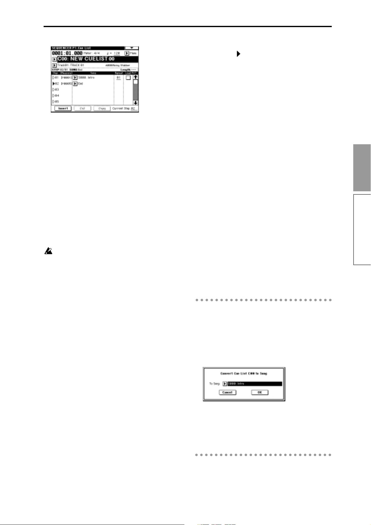
3 Press the Insert button three times. Steps 01–04
will become active.
4 Select a song for each “Step” 01–04.
Select S000: Intro for “Step” 01, S001: A for “Step”
02, S002: Bridge for “Step” 03, and S003: Ending for
“Step” 04.
5 In “Repeat,” specify the number of times that the
song at each step will repeat.
Set “Step” 01 to 02, “Step” 02 to 04, “Step” 03 to 02,
and “Step” 04 to 01.
6 If necessary, check the “Load FX?” check box.
This specifies whether or not the effect settings will
also be changed when the song at that step is
played. If you want the effect settings to change,
check this box. For this example, check “Step” 01.
Depending on the effect settings, a certain amount
of time may be required for the effects to be
switched. If this occurs, the playback will not be
smoothly connected from song to song.
To ensure a smooth transition from song to song,
check “FX Load?” for “Step” 01. Do not check “FX
Load?” for the remaining steps. This way, the
effect settings will be made before playback
begins, and there will be no time lag when cue list
playback is started or when switching from song
to song. Although it will not be possible to change
effect types within the cue list, you can use
dynamic modulation or MIDI control changes
such as Effect Control to control the effects within
the cue list, for example applying reverb more
deeply on certain songs, or raising the LFO speed
for a specific song. We recommend this method if
you will be using a cue list to construct the song.
When you execute the “Convert to Song” page
menu command, the effect settings of the “Step”
01 song will be specified for the song that results
from the conversion.
• “Step”: The arrow will indicate the currently
playing step. indicates the currently selected
“Step.” If you set “Current Step” while stopped,
the display will change.
• “Measure”: Indicates the starting measure of that
step.
• “Meter”: Indicates the currently-playing time
signature. This cannot be changed.
7 This completes the settings. Press the [START/
STOP] key to begin playback from the step specified in “Current Step.”
Intro (measures 1–4) → Intro (measures 5–8), A
(measures 9–16) → A (measures 17–24) → A (measures 25–32) → A (measures 33–40) → Bridge (mea-
sures 41–48) → Bridge (measures 49–56) → Ending
(measures 57–60)
• The name of a cue list can be specified by the
“Rename Cue List” page menu command.
• If you wish to use the tempo that is specified by
the song of each step, set “Tempo Mode” to Auto.
If this is set to Manu (manual), playback will use
the tempo that you specify in “ =”.
• If you specify Continue to Step01 for the last step,
the cue list will continue playing back repeatedly.
• If you set “Repeat” to FS, a foot switch connected
to the [ASSIGNABLE SWITCH] jack will control
the timing at which the song stops repeating. Set
“Foot Switch Assign” (Global P2: Controller) to
Cue Repeat Control.
• When you play the keyboard, the program of the
track selected by “Track Select” will sound. If a
different program is selected for each song, the
program specified for the currently playing song
will sound.
Converting a cue list to a song
Although it is not possible to record additional material onto tracks in a cue list, you can convert a cue list
to a song, and then record solos etc. to vacant tracks.
You will also need to convert a cue list to a song if you
wish to save it on a floppy disk as SMF data.
● Select the “Convert to Song” page menu com-
mand.
Basic functions
Sequencer mode
Even if “Load FX?” is not checked, there may be
cases in which a time lag in the transition between
songs, depending on the musical data of the song.
Also, there may be cases in which the musical data
is not played at the correct timing at the transition
between songs. If this occurs, you can edit the
musical data of the song, or convert the cue list to
a song for playback. If you use “Convert to Song”
to convert the cue list to a song, there will be no
time lag during playback at the transition between
songs, and the musical data will be played at the
correct timing.
In “To Song,” specify the destination song number
for the converted data. The cue list name will automatically be assigned as the song name of the converted data. (For details and cautions regarding
“Convert to Song,” refer to p.53 in the Parameter
Guide.)
71
Page 76

RPPR (Realtime Pattern Play/
Recording) function
For details on the RPPR function, refer to “Playing
with the RPPR function” (
example of how to make RPPR settings, and how to
playback and record.
RPPR settings
RPPR settings are made individually for each song. To
use RPPR playback, check the “RPPR” check box. If
this is checked, the RPPR function will be turned on,
and playing the keyboard will cause patterns to playback according to the RPPR settings. If the “RPPR”
check box is not checked, the song will play normally
even if RPPR settings have been made.
1 Make track settings just as when preparing to
record tracks.
Use steps 1–4 of “Preparations for recording”
(
☞p.64) to specify the program for the track.
2 In Sequencer mode P6: Pattern/RPPR, select the
RPPR Setup tab.
In this page, the RPPR function will automatically
be on.
☞p.33). Here we will give an
“Assign” check box. (You can make assignments for
keys C#2–C8. Keys C2 and below are used for stopping the pattern playback, and cannot be assigned.)
4 Select the pattern that will playback when you
press the key selected in step 3.
Use “Pattern” to select the pattern type (either Preset or User), and use “Pattern Select” to select the
pattern. A user pattern selected here must have
already been recorded or copied in the Pattern Edit
tab.
5 Select the track that will play this pattern.
The pattern will play according to the program and
other settings of the track you select here.
If you wish to play a drum pattern, choose a track
for which a drum program is selected. If you wish to
play a bass pattern, select a track for which a bass
program is selected.
6 Set “Mode,” “Shift” and “Sync” to specify how the
pattern will play, and how it will synchronize.
When you press the key to which the pattern is
assigned, the pattern will begin playing. The
method of stopping playback will depend on the
“Mode” setting, but pressing the C2 or lower key
will stop all patterns.
For details on these parameters and on how to stop
the playback, refer to p.71 in the Parameter Guide.
The assigned keys will be shown as a keyboard
graphic in the LCD screen.
3 Use “KEY” to select the key to which you wish to
assign a pattern.
You can also select a key by holding down the
[ENTER] key and playing a note. Check the
Song
Preset Patterns
P6: Pattern/RPPR page RPPR Setup tab
Unassigned keys can be used for normal keyboard
performance. Use “Track Select” to select the track
that will be played from the keyboard. For example you might assign backing patterns such as
drums and bass to the C#2–B2 keys and use these
keys to control pattern playback, and use keys C3
and above to play solos in realtime. It is a good
idea to keep the assigned keys together in this
way.
✓ RPPR
RPPR
RPPR function is on
Normal song playback and recording
U00: R&B Shuffle 1
User Pattern U00 - U99
72
Page 77

RPPR playback
Here’s how you can use the RPPR function to perform
in the P0: Play/REC page. You can also playback a
song while you perform with the RPPR function.
1 In Sequencer mode, select P0: Play/REC.
2 Check the “RPPR” check box. The RPPR function
will be turned on. The on/off setting is memorized
for each song.
3 Play the keyboard, and patterns will begin playing
according to the RPPR settings.
Keys to which no pattern is assigned can be used
for normal keyboard performance. (When you
change “Track Select,” the track played by the keyboard will change.)
If you wish to trigger the RPPR function from an
external MIDI device, use the MIDI channel that is
selected for “Track Select.”
4 To turn off the RPPR function, uncheck the RPPR
check box.
RPPR performance techniques
• Pattern playback for a key with a “Sync” setting of
Beat or Measure will synchronize to the pattern
playback of the first key. (For details refer to
“Sync” on p.71 in the Parameter Guide.)
• Pattern playback for a key with a “Sync” setting of
SEQ will synchronize to the playback of the song.
Start song playback, and then press the key. The
pattern playback will start in synchronization with
the measures of the song.
Synchronization will be lost if you use the
[<<REW] or [FF>>] keys while a song is playing.
If you want RPPR pattern playback to begin at the
moment that song playback begins, it is a good
idea to insert an empty measure containing no
musical data before the song playback begins.
If the song is stopped, the pattern will synchronize
to the timing of the arpeggiator.
Realtime recording an RPPR performance
Multitrack recording
You can use multitrack recording to simultaneously
record the performance of multiple tracks played by
the RPPR function.
The pattern will be recorded as musical data on the
track used by RPPR.
RPPR settings for recording are made in the P6: Pattern/RPPR tab RPPR Setup. Here if you set “Sync” to
SEQ, the pattern playback will be recorded in synchronization with the sequencer. For details on how the
“Sync” setting will affect the start timing of the pattern
playback (
With a setting of SEQ, patterns played by the RPPR
function while the sequencer is playing or recording
will start in synchronization with the measures of the
sequencer. The pattern of a key pressed during the precount before recording begins will start simultaneously
with the beginning of recording, and will be recorded.
1 Using the procedure described in “Preparations
2 In the P0: Play/REC tab Preference, set “Recording
3 Check the “Multi REC” check box.
☞p.71 in the Parameter Guide).
When recording the playback of patterns triggered
by RPPR, the timing of the recorded events may be
slightly skewed. If this occurs, try setting “Reso”
(Realtime Quantize Resolution) to a setting other
than Hi.
for recording” (
tings.
Your keyboard performance on keys that are not
assigned to the RPPR function will be recorded on
the track specified by “Track Select.”
Setup” to Over Write.
Multitrack recording can be used in Over Write,
Over Dub, Manual Punch In, and Auto Punch In
recording modes. Here we will describe the proce-
dure for the most commonly used overwrite
recording.
☞p.64), make the necessary set-
Basic functions
Sequencer mode
• If you are playing the pattern in synchronization
(when “Sync” is Beat, Measure, or SEQ), the
pattern will start accurately if you play the note
slightly earlier than the timing of the beat or
measure. Even if you play the note slightly later
than the beat or measure (but no later than a 32nd
note), it will be considered to have started at the
beat or measure, and the beginning of the pattern
will be compressed so that the remainder of the
playback will be correct.
4 Press the Program T01–08 or Program T09–16 tab.
The “PLAY/MUTE/REC” button of each track will
indicate REC. For the tracks that you do not wish
to record, press the “PLAY/MUTE/REC” button to
select either PLAY or MUTE.
You will record all tracks played by RPPR and the
keyboard performance track selected by “Track
Select.”
73
Page 78

For example if you are using tracks 1 and 2 for
RPPR playback and using track 3 for keyboard performance, you would set REC only for tracks 1, 2,
and 3 as shown below.
5 Check the “RPPR” check box.
The RPPR function will be on.
6 In “Location,” specify the point at which recording
will begin.
It will not be possible to change the location if you
are recording the song for the first time, so proceed
to step 7.
7 Press the [REC/WRITE] key, and then press the
[START/STOP] key.
It will not be possible to change the location if you
are recording the song for the first time, so proceed
to step 5.
5 Press the [REC/WRITE] key, and then press the
[START/STOP] key.
Recording will begin.
In the case of single track recording, only the track
specified by “Track Select” will actually be
recorded even if the RPPR performance consists of
multiple tracks. Of the patterns that are assigned
by the RPPR settings, only the performance of the
patterns whose track matches will be recorded.
6 Press the [START/STOP] key.
Recording will end, and the location will return to
the point at which recording began.
Recording will begin.
When you press a key to which a pattern is
assigned, that pattern will begin playing. Keys to
which no pattern has been assigned will sound as
usual for the track specified by “Track Select,” and
will be recorded.
If you want a pattern to begin playing at the
moment that recording begins, press the key during the pre-count. (Make sure that the RPPR
“Sync” is set to SEQ.)
8 Press the [START/STOP] key.
Recording will end, and the location will return to
the point at which you began recording.
9 To cancel multitrack recording, uncheck the
“Multi REC” check box in step 3.
Single track recording
You can also use single track recording to record an
RPPR performance.
1 Make track settings in the same way as for multi-
track recording.
2 In P0: Play/REC, check the RPPR check box.
The RPPR function will be turned on.
3 In the same way as for single track recording of a
normal song, use “Track Select” to select the track
that you wish to record.
4 In “Location,” specify the point at which recording
will begin.
74
Page 79

Sampling mode
The TRITON provides high-performance mono/stereo
sampling.
None of the multisample or sample data in Sampling mode is backed up when the power is turned
off. If you wish to keep this data, you must save it
on a floppy disk or external SCSI device (if the separately sold EXB-SCSI option is installed) before
turning off the power.
Immediately after the power is turned on, the TRITON will contain no multisample or sample data.
If you wish to playback or edit data, you must first
load previously-saved data from floppy disk or an
external SCSI device.
Features of sampling mode
• 48 kHz 16 bit linear mono/stereo sampling.
• 16 Mbytes of sample (waveform) data memory is
standard, allowing you to sample for
approximately 2 minutes 54 seconds in monaural,
or approximately 1 minute 27 seconds in stereo. By
installing 72 pin SIMM modules, you can expand
the memory to a maximum of 64 Mbytes, which
will allow you to record up to four 2 minute 54
second samples in mono (or four 1 minute 27
second samples in stereo), for a maximum total of
approximately 11 minutes 39 seconds of sampling
time. (For details on expansion, refer to p.237 in the
Parameter Guide.)
•A maximum of 1,000 multisamples and 4,000
samples can be created.
• In Disk mode you can load multisample/sample
data from a floppy disk or SCSI media (when the
separately sold EXB-SCSI option is installed).
• Korg format or AKAI (S1000/S3000) format
sample data, or AIFF or WAVE files can be loaded.
(When this data is loaded into the TRITON, it will
all be handled as Korg format sample data.)
• The external audio source that you are sampling
can be processed by the five insertion effects to
apply effects such as compressor, EQ, or lo-fi. The
LFO frequency or delay time of the effect can be
specified as a BPM value, which is highly effective
when sampling phrase loops etc.
• Both auto sampling and manual sampling can be
performed. With auto sampling, recording will
begin automatically when the input level exceeds a
specified threshold. In either method of sampling,
you can make pre-trigger settings.
• The audio input supports both mic and line level
signals.
• Data that is sampled can be immediately played
from the keyboard. It can also be converted into a
program by a simple operation, and used as an
element of the TRITON’s HI synthesis system.
Multisamples/samples that have been converted
into a program can be used in a combination or
song.
• The waveform can be viewed in the LCD screen,
and edited by a variety of waveform editing
commands that include rate convert (downsampling) and reverse playback.
• Start, loop start, and end addresses can be
specified in units of a single sample. Loop tune,
reverse playback, and loop lock functions are also
supported.
• The Use Zero function automatically detects zero
cross points, making it easy to find the beginning
or end of the sample, or click-free locations.
• The grid function displays a BPM-based grid on
the waveform display, helping you to create loops
or make waveform edits that match the desired
BPM.
• Each multisample allows you to create up to 128
indices. Each index consists of a sample
assignment, a key zone, an original key, a playback
pitch, and settings such as level.
• The “Keyboard & Index” display lets you edit a
multisample while viewing the assignments and
zones of each sample.
• The playback pitch of each index can be matched
to a desired BPM value by using the BPM Adjust
function (playback pitch adjust) to set the loop
frequency.
• Sample names and multisample names of up to 16
characters can be assigned. Sample names and
multisample names can also be viewed in Disk
mode (
☞p.132 “Translation” in the Parameter
Guide).
Basic functions
Sampling mode
75
Page 80

Pages in Sampling mode
How Sampling mode is orga-
● For the procedure of entering each page or modes,
refer to “Basic operation of the TRITON” (
P0: Recording Record samples. Select the sample or
multisample to record, make various
recording settings and AUDIO INPUT
settings. View the memory status.
P1: Sample Edit Perform waveform editing etc. on sam-
ples that were sampled or loaded in
Disk mode.
P2: Loop Edit Set sample playback parameters: Start,
Loop Start, End Address, Loop on/off,
and Reverse on/off.
P3: Multisample Edit multisamples. Set and edit the sam-
ple assignments, zone, and original key
etc.
P4: Controller Setup Controller settings.
P5: ---
P6: ---
P7: ---
P8: Insert Effect Select and make settings for the insert
effects used in sampling.
P9: ---
☞p.12).
Sampling can be performed in any page P0–P8 of
Sampling mode by using the [REC/WRITE] key
and the [START/STOP] key. Recording-related settings such as input level are made by the parameters of P0: Recording, and these settings are valid
for the other pages as well.
The selected multisample or sample can be played
from the keyboard in any page, allowing you to
hear the results of your editing in each page.
nized
In Sampling mode
• An external audio signal from an external audio
device or microphone connected to the AUDIO
INPUT 1 and 2 jacks is passed through an analog/
digital convertor, and recorded (sampled).
• You can edit the waveform and loop settings etc. of
sample data that you sampled or that you loaded
from a floppy disk, CD-ROM etc., in Disk mode.
• You can assign samples to the keyboard to create a
multisample. These samples and multisamples can
be easily converted to a program using the
“Convert MS to Program” page menu command,
and these programs can be used immediately in a
combination or song.
Sampling frequency and bit resolution
As shown in the diagram, sampling reads the level of
the analog signal at fixed intervals along the time axis,
and stores the levels in memory as digital data.
Level
Analog waveform
Level
48kHz
= 48,000 times every second
= 0.0208 mS cycle
Time
AUDIO INPUT jack
Analog signal
Used by combinations
and songs
Analog/digital
convertor
ADC
Insert Effects
Digital signal
Program
Sampled digital
waveform
RAM (SIMM memory):
16 MB (expandable to 64 MB)
Sample 0000 ... 3999
Multisample 000 ... 999
RAM (internal memory)
Digital signal
16bit
= 65,536 levels
Time
of data
Digital/analog
convertor
DAC
Analog signal
Floppy disk, SCSI media (Disk mode)
AUDIO OUTPUT
jack
76
Page 81

The “fixed intervals” mentioned above are generally
expressed as the “sampling frequency.” 48 kHz (kilohertz) means that sampling is performed 48,000 times
each second, and that the interval is 1 (second)/48,000
(times) = approximately 0.00002083 (seconds) =
approximately 0.02083 mS (millisecond).
The higher the sampling frequency is, the closer to the
original analog signal the waveform in memory will
be.
Each level is read, and converted into digital data. The
accuracy at this time is determined by the bit resolution. The infinite number of levels in the analog signal
are converted into digital data with a finite number of
levels. With 16 bit resolution, each level is indicated in
65,536 steps (the sixteenth power of two).
The greater the bit resolution is, the closer to the original analog signal the waveform in memory will be.
48 kHz 16 bit sampling is the same quality as in audio
devices such as DAT. A CD uses 44.1 kHz 16 bit sampling, which is a slightly lower sampling frequency.
Samples and Multisamples
Samples
The data that is recorded (sampled) into internal memory or loaded from a file is referred to as a sample or
sample file. Samples consist of the actual waveform
data, and parameters that specify how the data will be
played back, such as Start, Loop Start, and End
Address.
Samples can be used by multisamples and drum kits.
The TRITON can hold a maximum of 4,000 samples in
its internal memory.
Using multisamples
When sampling an instrument that is able to produce a
wide range of pitches, such as a piano, recording just
one sample and using it (playing it back) over the
entire pitch range will not produce a natural-sounding
result. By using a multisample and assigning a separately recorded sample to each portion of the pitch
range, you can produce a more natural sound. For
example, you might record one sample per octave, and
assign each of these samples to an index (keyboard
area). All of the instrumental sounds in the TRITON’s
internal preset ROM multisamples are constructed in
this way.
You can use a multisample to arrange multiple phrase
samples or rhythm loops across the keyboard, and play
two or more samples simultaneously. Since a different
phrase could be assigned to each key, you can perform
just as though you were using a pad-type sampler.
Alternatively, these samples could be assigned at oneoctave intervals, and played as phrase variations with
different playback pitches.
The TRITON can hold a maximum of 1,000 multisamples in its internal memory.
A multisample can be selected as the oscillator for a
program, and played as a program. In a combination,
they can be combined with preset programs, and used
in a song. They can be used with the arpeggiator to
produce interesting results (for example, by using the
arpeggiator to automatically play sound effects or spoken samples).
Index001
Top Key
Multisample
Index002
Top Key
Index003
Top Key
Index004
Top Key
Basic functions
Sampling mode
The TRITON can share a single waveform among
multiple samples. This allows you to create multiple samples with different playback addresses
from the same waveform without wasting internal
memory. For example, suppose that you have
waveform data that records a voice saying “OneTwo-Three.” This single piece of waveform data
could be shared by three samples, with the playback of sample A producing “One-Two-Three,”
sample B producing “One-Two,” and sample C
producing “Two-Three.” Refer to “Copy Sample”
(p.83) in the Parameter Guide.
Multisamples
A multisample consists of settings that make one or
more samples sound in different areas of the keyboard.
A multisample consist of between one and 128
“indexes.” Each index contains parameters that specify
the sample that will playback, the zone for which it
will playback, the original pitch key, the playback
pitch, and level etc.
Index 001
0000:
Sample A
Multisample
Sample
Index 002
0001:
Sample B
Drum Kit
Index 003
0002:
Sample C
Program OSC (Single/Double)
Program OSC (Drums)
Index 004
0003:
Sample D
77
Page 82

Sampling (recording a sample)
• Set “BUS (IFX) Select.” If you wish to use the
TRITON’s insert effects to process the incoming
sound, select IFX1–5 here. For this example, select
L/R. The input sound will be sampled just as it is.
Preparations for sampling
Connections and settings for a monaural source
When sampling in monaural from a mic, the output of
an external audio device or mixer, or an instrumental
sound such as guitar or synthesizer, connect the source
to the AUDIO INPUT 1 or 2.
Guitars etc. with active pickups can be input
directly, but instruments with passive pickups (i.e.,
without internal preamps) cannot be sampled at
an appropriate level, due to impedance mismatching. When connecting such instruments, use a
preamp or effect device.
Mic
1 Connect the mic or external audio device to the
AUDIO INPUT 1 jack.
2 Set the AUDIO INPUT [MIC-LINE] switch to
match the input source. For input sources with a
low input level, such as a microphone, select the
MIC position. For other sources, select the LINE
position.
The AUDIO INPUT [MIC-LINE] switch affects
both the AUDIO INPUT 1 and 2 jacks.
3 The AUDIO INPUT [LEVEL] knob will be
adjusted later. For now, set it near the center.
4 In Sampling mode P0: Recording, select the Input/
Setup tab.
Be aware that when you change the setting from
Off to L/R or IFX1–5, the volume level in the
AUDIO OUT L/MONO and R jacks and in the
headphones may rise excessively.
“Input 1” controls the AUDIO INPUT 1 jack, and
“Input 2” controls the AUDIO INPUT 2 jack.
The settings up to this point will cause the sound
from the AUDIO INPUT 1 jack to be output from
the AUDIO OUT L/MONO jack and from the L
channel of the headphones.
6 Use the AUDIO INPUT [LEVEL] knob to set an
appropriate level.
If the level is excessive at the TRITON’s input stage,
the display will indicate “ADC OVERLOAD !!”
(analog/digital converter is overloaded). Adjust the
AUDIO INPUT [LEVEL] knob or the output level of
the external audio device just low enough so that
the “ADC OVERLOAD !!” does not appear (i.e., the
maximum level that does not cause an overload).
Connections and settings for a stereo source
When sampling in stereo from a stereo mic, the output
of an external audio device or mixer, or synthesizer,
connect the source to the AUDIO INPUT 1 and 2 jacks.
CD player,
analog record player etc.
LINE OUT
1 Connect the L source to AUDIO INPUT jack 1, and
the R source to jack 2.
2 Make the settings described in steps 2–4 of
“Connections and settings for a monaural source.”
5 In “Audio Input (SAMPLING),” set various
parameters that specify how the signal from the
AUDIO INPUT jack will be received.
• “Level” adjusts the volume. Normally you will set
this to 127.
• “Pan” adjust the panning. For this example set it to
L000.
78
3 In “Audio Input (SAMPLING),” set various
parameters that specify how the signal from the
AUDIO INPUT jacks will be received.
• “Level” adjusts the volume. Set both Input 1 and
Input 2 to 127.
• “Pan” adjust the panning. Set Input 1 to L000, and
Input 2 to R127.
• Set “BUS (IFX) Select.” For this example, select L/R
for both Input 1 and Input 2.
The settings up to this point will cause the sound
from the AUDIO INPUT 1 and 2 jacks to be output
in stereo from the AUDIO OUT L/MONO and R
jacks and from the headphones. The sound of
AUDIO INPUT 1 will be output from the left, and
AUDIO OUTPUT 2 from the right.
Page 83

4 Use the AUDIO INPUT [LEVEL] knob to adjust a
suitable input level. (Refer to step 6 of “Connections and settings for a monaural source”)
The AUDIO INPUT [LEVEL] knob adjusts both
AUDIO INPUT 1 and 2.
Using an insert effect
The TRITON’s insert effects can be applied to the
sound that is being input from the AUDIO INPUT 1
and 2 jacks, allowing you to record a sample with
effects applied. As an example, we will explain the procedure for applying an insert effect to a stereo source
and sampling the result.
1 Make the settings of step 1 and 2 in “Connec-
tions and settings for a stereo source.”
2 Set the “Audio Input (SAMPLING)” parameters.
• Set “BUS (IFX) Select” to IFX1 for both Input 1
and 2.
• Set “Level” and “Pan” to the same settings as in
step 3 of “Connections and settings for a stereo
source.” With these settings, the stereo source
will be sent to insert effect 1 (IFX 1).
3 Use the AUDIO INPUT [LEVEL] knob to adjust a
suitable input level. (Refer to step 6 of “Connections and settings for a monaural source.”)
4 In P8: Insert Effect, select the Insert Fx tab.
Manual sampling
There are two methods of sampling: manual and auto.
In manual mode, sampling is started by pressing the
[START/STOP] key from the recording standby condition (entered by pressing the [REC/WRITE] key once).
For the sampling procedure in auto mode, refer to
“Auto sampling” (
1 In P0: Recording, select the Input/Setup tab.
2 Use the “Recording Setup” radio buttons to select
Manual.
This will select manual recording mode.
Recording Setup
3 In P0: Recording, select the Recording tab.
☞p.80).
MS
Basic functions
Sampling mode
Chain
Up to five insert effects can be connected in series.
Make settings for “Chain,” “Insert Effect,” and the
“Pan” of the sound after it has passed through the
insert effect. For details on the settings, refer to
p.109, 107, and to p.26, 99 in the Parameter Guide.
Examples of settings using the insert effects are
given in “Sample Mode” (p.82) in the Parameter
Guide.
Sample Select
Sample Mode
Recording Level [dB] meter
Recording Level [dB] slider
4 Select “MS” the multisample (MS). For this exam-
ple, select 000: NewMS______000.
Immediately after the power is turned on, 000:
NewMS______000 will be created automatically.
Use the numeric keys [0]–[9] to input the multisample number that you wish to record, and press the
[ENTER] key. Alternatively, you can press the
popup button and select a multisample from the
popup menu. If you select a new number, the Create
New Multisample dialog box will appear. Press the
OK button.
To specify the name, use the “Rename MS” page
menu command.
79
Page 84

5 In “Sample Select,” select the sample that you
wish to record. For this example, select ----: ---No
Assign----.
Immediately after the power is turned on, this will
be set to ----: ---No Assign----. You may sample even
in this condition. The sample will be automatically
recorded to a vacant sample number.
If you wish to first specify a sample number to
which the sample will be recorded, use the numeric
keys [0]–[9] and [ENTER] key or the popup menu to
select the number.
A sample will be created automatically when you
record.
A sample name such as 0000: NewSample_0000
will be assigned automatically. This name can be
edited using the “Rename Sample” page menu command.
If you execute sampling when an existing sample
such as 0000: NewSample_0000 is selected, the new
sample will be sampled to a vacant sample number.
You do not need to be concerned with this setting
even when you continue recording successive samples.
6 Select the “Sample Mode.”
Monaural source: If the “Audio Input (SAM-
PLING)” setting “Pan” is L000, set “Sample Mode”
to L-Mono. If “Pan” is R127, set “Sample Mode” to
R-Mono.
Stereo source: Set the “Sample Mode” to Stereo.
7 Press the [REC/WRITE] key.
If an input signal is present, the Recording Level
[dB] meter will move according to the Pan setting in
“Audio Input (SAMPLING).” This is the recordingstandby condition.
In the case of “Connections and settings for a monaural source,” the L meter will move. In the case of
“Connections and settings for a stereo source,” the L
and R meters will move.
Use the “Recording Level [dB]” slider to adjust the
level. For this example, set the slider to the 0.0 set-
ting (
☞p.82 in the Parameter Guide).
8 At the moment that you wish to begin sampling,
press the [START/STOP] key.
Sampling will begin.
9 Sampling will stop when you press the [START/
STOP] key once again.
Sampling will stop automatically when the
remaining amount of memory reaches zero.
0 Play the C2 note on the keyboard.
The sample you recorded will play back.
If you wish to continue recording samples, repeat
steps 6–9.
Auto sampling
There are two ways to record a sample: manual and
auto.
With auto, sampling will begin when the input signal
exceeds the specified threshold level. For details on
manual sampling, refer to “Manual sampling” (
1 In the P0: Recording, select the Input/Setup tab.
2 Use the “Recording Setup” radio buttons to select
Auto.
This will select auto recording mode.
3 Set the “Threshold.”
When the input signal exceeds the “Threshold”
level, sampling will begin automatically. The black
triangles at both sides of the Recording Level [dB]
meter display will indicate the specified level.
When you use auto sampling, the attack portion of
the sampled input sound may be lost, depending
on the “Threshold” setting. If this occurs, you can
use “Pre Trigger REC” to sample the sound that
occurs before sampling actually begins. Normally
you will set this to 0, and use it only when necessary.
4 In P0: Recording, select the Recording tab.
5 Select the “MS” (multisample) (refer to “Manual
sampling” step 4).
6 Select the sample in “Sample Select” that you wish
to record (refer to “Manual sampling” step 5).
7 Specify the “Sample Mode” (refer to “Manual
sampling” step 6).
8 Press the [REC/WRITE] key.
9 Press the [START/STOP] key.
When the input signal exceeds the “Threshold”
level, sampling will begin automatically.
0 Sampling will stop when you press the [START/
STOP] key once again.
Sampling will end automatically if the remaining
amount of memory reaches zero.
A Play the C2 note on the keyboard, and you will
hear the sound that you sampled.
☞p.79).
80
Page 85

Creating multisample indexes and sampling
4 Select “Index.”
“Index” can also be selected by holding down the
[ENTER] key and playing a note on the keyboard.
For this example, select 001.
Index
Keyboard & Index
Create button
Here’s how to create indexes for a multisample, and
assign a sample to each index.
If desired, you can first create several indexes for a
multisample, and then record a sample for each index.
1 In P0: Recording, select the Recording tab.
2 Select the “MS” (multisample) (refer to “Manual
sampling” step 4).
3 Press the Create button to create an index.
Immediately after the power is turned on, the
“Index” will be indicated as 001/001. This means
that there is only one index. The range that is highlighted in the keyboard & Index is the range of the
selected index.
5 If you have been sampling previously and one or
more samples already exist, use “Sample Select” to
select the sample that you wish to assign.
Repeat steps 4 and 5 to assign a sample to each
index. Complete the multisample in this way.
When you play the keyboard in the area of an index
to which a sample has been assigned. that sample
will play back.
6 If you wish to first create two or more indexes for
the multisample before you start sampling, and
then continue sampling for each of these indexes,
select the index for sampling in step 4, and use
either manual sampling or auto sampling to record
a sample for that index (
“Auto sampling”).
Create a multisample by selecting an index and then
sampling.
The number and order of the indexes in the multisample, the zone of each index, and the original
key location can be edited later if desired (
“Multisample editing”).
☞“Manual sampling” or
☞p.84
Basic functions
Sampling mode
Press the Create button several times. Each time
you press it, an index will be created. The keyboard
display will indicate the zone and original key location of each index. The highlighted area is the currently selected index.
The index that is created when you press the Cre-
ate button is created according to the “Create Zone
Preference” settings of the Preference tab. For
details refer to p.87 and “Create” (p.81), both in the
Parameter Guide.
Immediately after the power is turned on, “Position” will be Right, “Zone Range” will be 12Keys,
and “Original Key Position” will be Bottom, so
that indexes will be created as shown below.
If you set “Zone Range” to 1Key, an index will be
created for each note of the keyboard and a sample
assigned to in index. You can then continue sampling. It is convenient to use 1Key when you wish
to sample numerous takes in succession, such as
when recording phrases or rhythm loops.
81
Page 86

Loop settings
With the default settings after the power is turned on,
the sounds you sample will automatically be looped
(P0: Recording page Preference tab “Auto Loop On.”)
To edit the loop and other playback address settings
for the sample, use the P2: Loop Edit page.
1 Select P2: Loop Edit.
Keyboard & Index
Sample Select
3 Use the “Loop On” check box to turn loop play-
back on/off. When the box is checked, looping will
be on.
Loop On: “Start” → “End” → “LoopS” → “End”
→ (“LoopS” → “End”) repeated
Loop Off: “Start” → “End”
4 If necessary, use the page menu command “Trun-
cate” to delete unwanted data that falls outside the
start (or loop start) and end addresses.
ZOOM button
The waveform data for the currently selected sample will be displayed. It will play back “Keyboard &
Index” when you play the highlighted in the Keyboard when you play the highlighted in the area.
You can use “Sample Select” to select the sample
that you wish to edit. When you do so, the assignment to the index will also change. When you
change indexes, the waveform data for the sample
assigned to that index will appear.
Waveform data for a sample that was sampled
with a “Sampling Mode” of Stereo will be displayed in two lines. The upper line is the waveform display for the L channel, and the lower line
is for the R channel.
2 Specify the start address in “Start,” the loop start
address in “LoopS,” and the end address in “End.”
Press “Start” (it will be highlighted), and use the
[VALUE] controllers to change the setting. The corresponding vertical line will move. Set “LoopS” and
“End” in the same way. In the example shown
below, “Start” is immediately before the first waveform, “LoopS” is immediately before the second
waveform, and “End” is set to an arbitrary location.
Start LoopS End
Set the parameters, and press the OK button to
execute the operation.
☞p.95 in the Parameter Guide
For cautions regarding “Save to No.” and the
“Overwrite” check box (
☞p.83 “A note on saving
samples”).
The grid display
The page menu command “Grid” overlays the waveform display with a grid based on the BPM tempo
value. This makes it easy to make loop settings that are
synchronized to the tempo.
In the same way, the grid display can also be used
in P1: Sample Edit. The grid can help you to edit
the waveform in synchronization with the tempo.
1 Select the page menu command “Grid.”
Turn the radio button On, set the “Resolution” as
desired, and press the OK button. A dotted grid
will be displayed.
2 Set “Grid” to the desired BPM tempo value.
By using the ZOOM buttons you can change the
range that is displayed. When “Start” is highlighted, zoom will be performed from the start
address (
☞p.88 in the Parameter Guide).
If the “Use Zero” check box is checked, only those
addresses where the waveform data crosses the
zero level will be found automatically when
searching, and can be set. This lets you easily make
address settings where noise is less likely to occur
when looping.
82
3 Set the end address so that it coincides with a dot-
ted line of the grid.
This will cause the loop interval to be the same
length as the BPM value.
The grid display will be based at “LoopS” if looping
is on. If looping is off, the grid will be based at
“Start.”
4 To cancel the grid display, select the “Grid” page
menu command, set the radio buttons Off, and
press the OK button.
Page 87

The grid is displayed according to the playback
pitch of the base key (the key shown in gray in the
“Keyboard & Index” area).
You can select the base key by holding down the
[ENTER] key and playing a note on the keyboard.
Sample (waveform data) editing
Editing the waveform data of the sample is done in P1:
Sample Edit. You can use commands such as cut, copy,
and normalize to edit the waveform data.
1 Select P1: Sample Edit.
Keyboard & Index
The waveform data of the currently selected sample
will be displayed. It will play back when you play
the keyboard (in the highlighted region in the “Keyboard & Index”).
You can use “Sample Select” to select the sample
that you wish to edit.
When you change indexes, the waveform data of
the sample specified for that index will be displayed.
For details on each command (
ter Guide).
☞p.89 in the Parame-
A note on saving samples
In the dialog boxes of some page menu commands,
there is a “Save to No.” setting that lets you specify the
sample number to which the edited sample will be
saved. At this time, a vacant sample number will be
selected automatically, so you will change the setting
only if you want to specify the save destination number.
If you check “Overwrite” in the dialog box of the command, the data prior to editing will be deleted, and
will be overwritten by the edited data. Normally, you
will leave this unchecked, so that the data prior to editing will be preserved as you edit. Samples that are no
longer needed when you have completed your editing
can be deleted by the “Delete Sample” page menu
command.
In Sampling mode, there is no Compare function
that lets you compare the data before and after
editing.
If you wish to preserve the unedited state of the
multisample or sample, use “Copy MS” or “Copy
Sample” (
the multisample or sample before you begin editing it.
For some page menu commands in P1 or P2, you
can execute without checking the “Overwrite” setting in the dialog box, so that the sample data previous to editing will be preserved.
☞p.83, 84 in the Parameter Guide) to copy
Basic functions
Sampling mode
Sample waveforms that were recorded with a
“Sampling Mode” of Stereo will be shown in two
lines. The upper line is the L channel waveform,
and the lower line is the R channel waveform.
2 Use “Edit Range Start” and “Edit Range End” to
specify the range that you wish to edit.
The selected range will be highlighted.
If you wish to audition the selected range, press the
[START/STOP] key.
The waveform will play back at the pitch of the base
key (the key shown in gray in the keyboard display). You can select the base key by holding down
the [ENTER] key and playing a note on the keyboard.
The ZOOM buttons and the “User Zero” check
box can be used in the same way as in P2: Loop
Edit.
3 From the list of page menu commands, select the
desired editing command. Make the appropriate
settings in the dialog box, and press the OK button
to execute.
83
Page 88

Multisample editing
Editing a multisample consists of creating indexes for
the multisample and assigning a sample to each index
(these basic settings can also be performed in P0), editing operations such as deleting, copying, and inserting
indexes, and detailed settings such as sample level and
pitch for each index.
Multisample editing is performed in P3: Multisample.
Editing the indices
To change the number or order of the indexes, use the
Insert, Cut, Copy, and Create buttons.
1 Press P3: Multisample.
• “Pitch” adjusts the sample pitch for each index.
You can use the “Pitch BPM Adjust” page menu
command to set the loop interval to a desired BPM
value (
☞p.97 in the Parameter Guide).
Converting a multisample to a
program
In pages P0–P4, you can select and execute the “Convert MS To Program” page menu command. When you
execute this command, the settings of the currently
selected multisample will be converted into a program.
In Program mode you can make filter, amp and effect
settings etc., and play the sample as a program. The
resulting program can be used in a combination or
song.
For details on the “Convert MS To Program” page
menu command (
☞p.84 in the Parameter Guide).
2 Use Multisample (MS) to select the multisample
that you wish to edit.
3 Select the “index.”
You can also select an index by holding down the
[ENTER] key and playing a note on the keyboard.
4 Press the buttons to modify the number or order of
the indices, and edit them.
To delete the selected index, press the Cut button.
The Insert button is used in conjunction with the
Cut and Copy buttons. The contents of the index
that was Cut or Copied will be inserted.
The Create button has the same function as the Cre-
ate button in P0: Recording (
sample indexes and sampling”).
☞p.81 “Creating multi-
Modifying the settings of an index
1 Make the settings described in steps 1–3 of
“Editing the indexes.”
2 Set parameters for the selected index.
For details on each parameter, refer to p.96 in the
Parameter Guide.
• Changing the “Top Key” will change the upper
limit of the zone. Simultaneously, the lower limit
of the next-numbered index will also change.
• If you check “Constant Pitch,” all notes in the
index zone will sound the sample at its original
pitch.
84
Page 89

Song Play mode
In Song Play mode you can read Standard MIDI Files
(SMF) directly from a floppy disk and play them. If
you simply want to play an SMF without editing it, it
will be convenient to select this mode.
The pages in Song Play mode
● For details on how to access these pages or modes,
refer to “Basic operation of the TRITON” (
P0: Program/Mix Play SMF data and make settings.
P1: Track Make MIDI and scale settings for each
P2: Controller Setup Controller settings.
P3: Select Directory/
Jukebox
P4: ---
P5: ---
P6: ---
P7: Arpeggiator settings
P8: Insert Effect Select and make settings for insert
P9: Master Effect Select and make settings for the master
Specify the program, pan, and level for
each track.
track. If the separately sold EXB-MOSS
option is installed, set related parameters.
Select the directory that contains the
desired SMF, and select the playback
order of SMF files. Create jukebox lists.
effects. Make settings for the routing,
insertion effects, master effects, and
individual output assignments of each
track in the song.
effects. Master EQ settings.
If the separately sold EXB-MOSS is installed, the
special bank F can be used in Song Play mode as
well. For details on the bank F parameters, refer to
the EXB-MOSS owner’s manual.
☞p.12).
The parameter settings of Song Play mode are not
backed up when the power is turned off. If you
wish to save the program, track parameter, and
effect settings of the song, use the page menu command “Save Template Song” to save them. If you
wish to play SMF song data, you must first load it
from external media such as a floppy disk.
The structure of Song Play mode
As shown in the diagram below, Song Play mode consists of tracks 1–16, effects and arpeggiator.
About SMF
SMF data in format 0 or format 1 can be played back in
Song Play mode.
The TRITON recognizes only files with an extension of
.MID as SMF data. Be sure that the filename extension
is .MID.
About MIDI
Track status settings in Song Play mode
You can select whether the musical data played by a
track, or the data produced by operating the TRITON’s
keyboard and controllers will sound the TRITON’s
internal tone generator, and/or will sound an external
tone generator.
When the “Status” of a track is set to INT, the data
played back by that track and the data produced by
operating the keyboard or controllers of the TRITON
will play and control the TRITON’s internal tone generator.
Basic functions
Song Play mode
Track 1
Track 2
Track 3
Track 4
Track 5
Track 6
Track 7
Track 8
Track 16
Parameter settings
Parameter settings
Parameter settings
Parameter settings
Parameter settings
Parameter settings
Parameter settings
Parameter settings
Parameter settings
Musical data
Musical data
Musical data
Musical data
Musical data
Musical data
Musical data
Musical data
Musical data
Routing : P8-1
Track
Insert Effect
Master Effect
Individual Outputs
Insert Effect 1 ... 5 : P8
Master Effect 1, 2 : P9
Controller Setup : P2
MasterEQ : P9
Arpeggiator : P7
AUDIO OUTPUT
L/MONO, R
AUDIO OUTPUT
INDIVIDUAL 1,2,3,4
85
Page 90

When the “Status” of a track is set to EXT or BTH, the
data played back by that track and the data produced
by operating the keyboard or controllers of the TRITON will play and control an external tone generator.
(The MIDI channel of the external tone generator must
match the “MIDI channel” of the TRITON track that is
set to EXT or BTH.) With a setting of BTH, the external
tone generator and the TRITON’s own tone generator
will be played and controlled simultaneously. (
in the Parameter Guide “Status”)
☞p.104
Playing SMF data
Direct playback from external media such as
a floppy disk
When you wish to playback SMF data that is compatible with the GM/GS/XG standards, set “Bank
Map” (Global P0: System Pref. tab) to GM(2).
1 Press the [S.PLAY] key to enter Song Play mode.
2 Insert a floppy disk containing SMF data into the
TRITON’s disk drive.
GM/GS/XG playback
When you wish to playback SMF data that is compatible with the GM/GS/XG standards, set “Bank Map”
(Global P0: System Pref. tab) to GM(2) (
(
☞p.115 in the Parameter Guide).
Synchronization with external devices
In Song Play mode, the TRITON will be the master (the
controlling device) regardless of the MIDI Clock setting (Global P1: MIDI “MIDI Clock”) (
☞p.123).
☞p.122).
Mute/Solo function
In P0: Play/Mix, the Program T01–08 and T09–16 tabs
provide PLAY/MUTE buttons and SOLO ON/OFF
buttons that allows you play and mute tracks 1–16 in
the same way as in Sequencer mode.
You can use these when you wish to mute the melody
track and play the part yourself on the keyboard
(“minus-one play”), or when you wish to audition a
track (
☞p.62).
You can use the “Solo Selected Track” page menu command to audition only the currently selected track.
This provides a convenient way to hear the parameter
settings and effect settings of a track (
Parameter Guide).
☞p.47, 102 in the
Insert effects and master effects
Refer to “About effects” (☞p.108) (☞p.109 in the Param-
eter Guide).
When the separately sold EXB-SCSI option is
installed. If you wish to load data from external
SCSI media such as a hard disk, refer to the EXBSCSI owner’s manual, and make sure that the external SCSI drive etc. is connected. Also make sure that
the media contains SMF data.
3 Press either the [LOCATE], [START/STOP], or
[PAUSE] key.
Data will be loaded from the media.
If you press the [START/STOP] key, the data will be
loaded and playback will begin (the same as in step
6).
4 “File Select” will show the SMF filenames.
File Select
If there is no SMF data in the floppy disk, or if there
is no SMF data in the currently selected directory, no
filename will be displayed (as shown below).
86
If no jukebox list has been created, no filenames will
be displayed if the “Jukebox” check box is checked.
Uncheck the “Jukebox” check box.
Page 91

To move to a directory that contains SMF data, press
the [MENU] key, and then press “P3: Select Directory” to display P3: Select Directory.
Playback using the Jukebox
function
The TRITON provides a Jukebox function that can be
used to playback SMF data.
This function allows you to specify the order in which
files in the same directory will be played.
A jukebox list you create will be erased when the
power is turned off, and can not be recovered. If
you wish to keep your jukebox list, refer to the section“Saving a Jukebox list” (next page), and save it
on external media.
If the separately sold EXB-SCSI option is installed
and a hard disk etc. is connected, press the drive
select button to select the drive that contains the
desired data.
Then press the Open button or Up button to move
between levels, and find the desired SMF.
When the SMF file (make sure that the extension is
.SMF) appears in the LCD screen, press the [EXIT]
key, and move to P0: Prog/Mix.
5 Press the “File Select” popup button. From the file
list, choose the filename that you wish to play
back.
File Select
6 Press the [START/STOP] key.
Playback will begin. At this time, all songs displayed in the “File Select” popup button will playback consecutively (if “Auto Start” is checked).
7 Press the [START/STOP] key once again to stop
playback.
1 Check the “Jukebox” check box.
2 Select P3: Jukebox.
Basic functions
Song Play mode
If the separately sold EXB-SCSI option is installed
and a hard disk etc. is connected, press the drive
select button to select the drive that contains the
data you wish to play back.
3 Use the scroll bar to display the SMF (filename
extension .MID) that will be played first, and
select that file.
4 Press the Add button.
The filename you specified in step 3 will appear in
the Jukebox list.
5 Select the file that will be played second, and press
the Add button.
Add files to the Jukebox list in the order that they
will be played. A maximum of 100 files (00–99) can
be registered in the Jukebox list.
Starting/stopping playback for each song
In the P0 Preference tab, uncheck “Chain to next file”
or “Auto Start,” and press the [START/STOP] key.
Playback will begin, and will stop when each song
ends. For details on these settings, refer to p.103 in the
Parameter Guide.
To delete a file from the Jukebox list, press the
Delete button.
6 Press the [EXIT] key to display P0: Play/Mix.
7 Press the [START/STOP] key.
The files will playback in the order in which they
were registered.
8 Press the [START/STOP] key once again to stop
playback.
Only files in the same directory can be registered
in a jukebox list.
If you perform the following operations while creating a jukebox list, the jukebox list will be lost.
87
Page 92

• Change the directory
• Remove the floppy disk
• Change drives
Saving a Jukebox list
Playing along with SMF data
Minus-one play
You can enjoy “minus-one” play by playing back SMF
data, muting a specific part, and playing that part
yourself.
Saving procedure
1 Use the procedure described above to create a
jukebox list.
2 If the separately sold EXB-SCSI option is installed
and you wish to save the list on a hard disk etc.,
use the P3: Jukebox drive select button to select the
drive in which you wish to save the data.
3 In P3: Jukebox, select the “Save Jukebox List” page
menu command.
4 Use the text edit button to enter a name for the
jukebox list (
5 Press the OK button.
The jukebox list will be saved to the media.
☞p.38).
Loading procedure
1 In the Jukebox page, select a jukebox list (filename
extension .JKB).
2 Press the “Load Jukebox List” page menu com-
mand.
The jukebox list will be loaded into the TRITON.
1 Playback the SMF data, identify the track whose
part you wish to play, and stop playback (
2 In P0: Prog/Mix, select the Prog. 1–8 tab or Prog. 9–
16 tab.
3 Use “Play Track Select” to select the track for the
part that you want to play from the keyboard.
When you play the keyboard, the program of the
selected track will be heard.
4 Press the “PLAY/MUTE” button to set the track
selected in step 3 to MUTE.
If you want the musical data of the track to playback
in addition to your own playing on the keyboard,
set “Play/Mute” to PLAY.
5 Press the [START/STOP] key to begin playback,
and play along on the keyboard with the song.
☞p.86).
88
Arpeggiator
During “minus-one” play, you can use the arpeggiator
for your keyboard performance (
Parameter Guide)
☞p.98). (☞p.107 in the
Page 93

Global mode
In Global mode you can make settings that affect the
entire TRITON, such as user scales, category names,
drum kits, and user arpeggio patterns.
This chapter will describe the procedure for editing a
drum kit. For the procedure of editing an user arpeggio pattern, refer to “Arpeggiator settings” (
For details on the parameters of other pages (
(
☞p.113 in the Parameter Guide)
When you play the keyboard in Global mode, the
TRITON will sound as in the previous mode in
which you were previously. Be aware that if you
moved from Sampling mode to Global mode in a
state where the sampling memory contained no
data (such as immediately after the power is
turned on), playing the keyboard will not produce
sound.
When you move from Sequencer or Song Play
mode to Global mode, playing the keyboard will
sound the program or arpeggiator that corresponds to the global MIDI channel (set in Global
P1: MIDI page).
☞p.96).
☞p.125).
About the pages in Global mode
● For details on how to enter each page or modes,
refer to “Basic operation of the TRITON” (
P0: Basic Setup Basic settings for the entire TRITON.
Audio input settings for use outside of
Sampling mode.
P1: MIDI MIDI-related settings for the entire TRI-
TON.
P2: Controller Controller settings for the pedals etc. con-
nected to the rear panel.
P3: User Scale User registered scale settings. Specify 16
octave scales, and one all-note scale.
P4: Category Name Edit category names for programs and
combinations.
P5: Drum Kit Edit drum kits.
P6: User Arpeggio Edit user arpeggio patterns.
P7: ---
P8: ---
P9: ---
☞p.12).
Basic functions
The settings that you edit in Global mode are preserved as long as the power remains on, but will
be lost when the power is turned off. The data handled in Global mode can be classified into three
types: drum kit settings (P5), user arpeggio pat-
tern settings (P6), and all other global settings
(P0–P4). Each of these three types of data can be
written into the memory area. In Disk mode, this
data can also be saved on external media such as a
floppy disk (
Global mode does not provide a Compare function
that lets you make before-and-after comparisons
of your editing. Before editing global settings,
drum kits, or user arpeggio patterns, you may
wish to use “Copy Drum Kit” or “Copy Arpeggio
Pattern” to copy the drum kit or user arpeggio pattern to an unused number.
☞p.39).
Global mode
89
Page 94
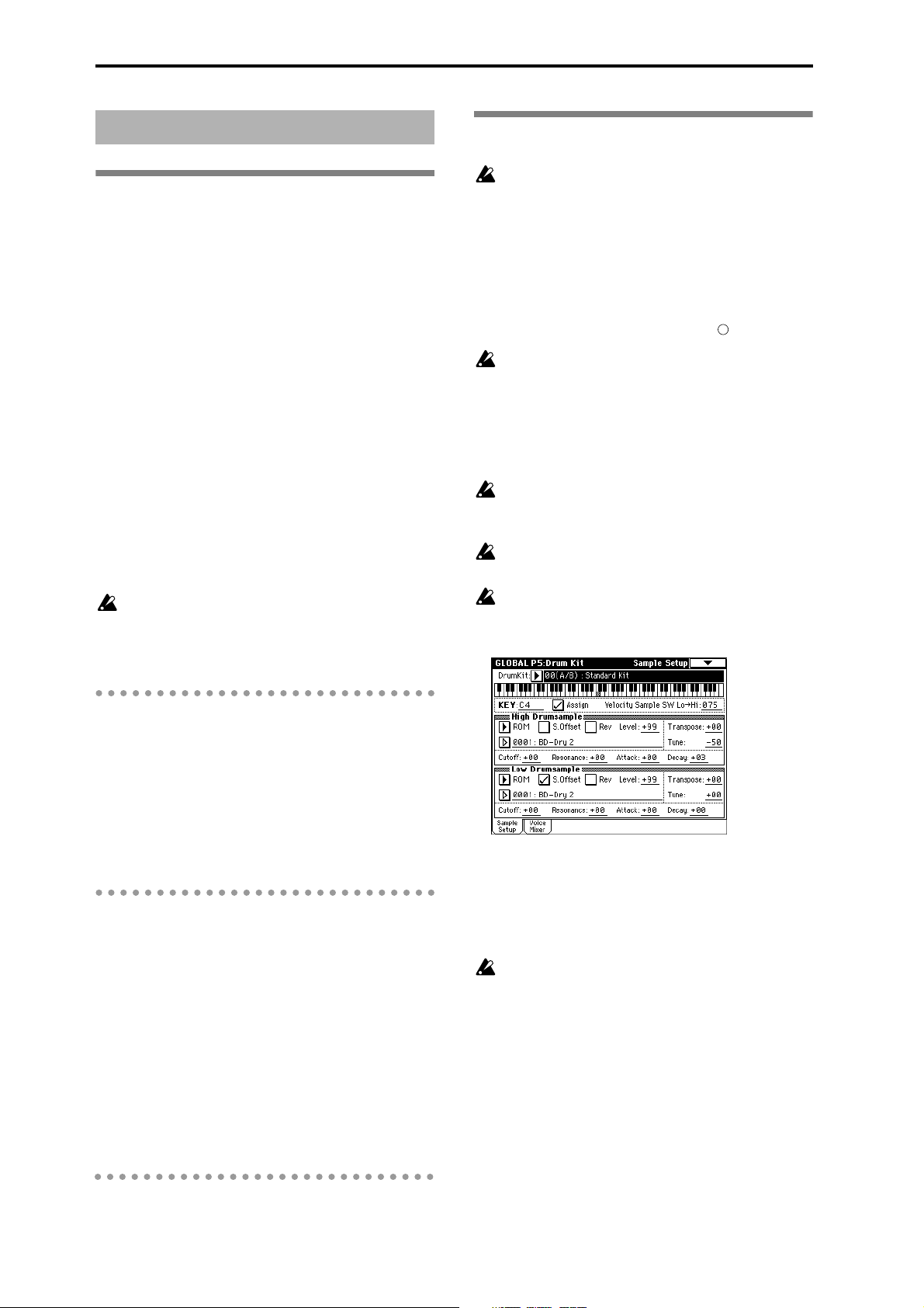
Creating a drum kit
About drum kits
A drum kit assigns a drumsample (PCM waveform
data for a drum) to each key, and specifies adjustments
in pitch and level etc. for each sample.
The TRITON contains 73 drum kit memory areas. With
the factory settings, 00–15 (A/B) contain preset drum
kits suitable for various styles of music. ROM memory
areas 64–72 (GM) contain nine different drum kits
compatible with the GM2 sound map.
For the factory preset drum kits, refer to the separate
Voice Name List.
In Global P5: Drum Kit you can modify these preset
drum kits, or create your own original drum kit from
an initialized condition. You can also create original
drum kits using sample waveforms that you sampled
in Sampling mode or loaded into memory in Disk
mode.
A drum kit that you edit or create can be written into
one of the drum kit memory areas 00–63. In Disk
mode, you can save drum kits on external media such
as a floppy disk (
16(C)–31 and 32(D)–47(D) are provided for the
preset patterns of separately sold EXB-PCM series
option boards. Please use 48–63 (User) to write the
drum kits that you create.
☞p.39, p.40).
Editing a drum kit
Before editing a drum kit, uncheck the Memory
Protect (
1 In Program mode P0: Play, select the program that
you wish to use while editing the drum kit.
Select a drum kit program from the preset programs
etc. If the drum kit that you will be editing is
already being used by a program, select that program. (In the separate Voice Name List, programs
that use a drum kit are marked by a symbol.)
When you wish to edit a drum kit, first use Program mode to select a program that uses a drum
kit (whose “Oscillator Mode” is Drums), and then
move to this page. A program that uses a drum kit
will have filter, amp, and effect parameter settings
etc. suitable for drum sounds (
parameter”).
Set “Octave” to +0 [8']. With a setting other than +0
[8'], the relation between the keys and the sounds
will be incorrect (
The effects will sound using the settings of the
last-selected program.
When you edit a drum kit, all programs that use
that drum kit will be affected.
2 In P5: Drum Kit, select the Sample Setup tab.
☞p.37).
d
☞“About program
☞p.6 in the Parameter Guide).
Multisample programs and drum kit programs
There are two types of programs: those whose oscillator uses a multisample, and those whose oscillator
uses a drum kit.
This selection is made by the Program P1: Program
Basic tab “OSC Mode” setting. To use a multisample
for the program, set “Oscillator Mode” to Single or
Double. To use a drum kit, set “Oscillator Mode” to
Drums.
About program parameters
Just as the character and effect processing of a melodic
instrument such as piano, organ, trumpet, and strings
is fundamentally different from that of percussion
instruments such as drums or timpani, the program
parameter structure of a multisample program (“Oscillator Mode” to Single or Double) is fundamentally
different from that of a drum kit program (“Oscillator
Mode” to Drums).
Since it is difficult to convert multisample program
parameters for use as a drum kit (because the filter and
amp settings etc. are made with a multisample program in mind), it is best to first select a drum kit program in Program mode, and then edit it in Global
mode.
3 In “Drum kit Select,” select the drum kit that you
wish to edit.
If necessary, use the “Copy Drum Kit” page menu
command to copy settings from a preset drum kit or
a GM drum kit.
GM drum kits 64–72 (GM) cannot be selected here.
(It is not possible to edit or write a GM drum kit.)
If you wish to modify the settings of one of the
drum kits 64–72 (GM), you can use “Copy Drum
Kit” to copy it to 00–63, and then edit the copy.
4 Press “KEY.”
5 Select the note number that you wish to edit.
You can select a note number by the [VALUE] controllers and also, holding down the [ENTER] key
and playing a note on the keyboard.
The parameter settings for the drumsample of the
selected note number will appear.
90
Page 95

6 Refer to the explanations below for the “Sample
Setup tab” and “Voice/Mixer tab,” and make the
desired settings.
The parameters are located in the Sample Setup tab
and the Voice/Mixer tab.
7 As necessary, repeat steps 4–6 to set the parame-
ters for each key.
To change the drum kit name, use the “Rename
Drum Kit” page menu command (
8 If you wish to save the edited drum kit into inter-
nal memory, be sure to Write the drum kit.
☞p.38).
About ROM drumsamples
The TRITON contains 413 drumsamples in its internal
ROM memory.
When you press the popup button, the ROM drumsamples will be displayed in 15 different categories.
You can use the tabs located at the left and right to
select a category, and choose drumsamples from the
selected category in the LCD screen.
For the drumsample names, refer to the separate Voice
Name List.
If you turn off the power without writing, your
edits will be lost (
☞p.39).
Sample Setup tab
Assign
Normally you will check this. The settings of each
parameter will be valid. If this is unchecked, drum-
sample parameters will not be assigned to that key.
Playing that key will sound the settings of the key to its
right, at a pitch one semitone lower. Use this when you
wish to play a tom or cymbal with the same settings
but with a different pitch.
Velocity Sample SW Lo → Hi
You can specify different drumsamples for High
Drumsample and Low Drumsample, and use velocity
(keyboard playing dynamics) to switch the drumsample that will sound. This is referred to as velocity
drumsample switching.
☞ This function is similar to the velocity multisample
switching of a program (
Low”).
If you are not using this function, set the “Velocity
Sample SW Lo → Hi” value to 001. When you play,
only the High Drumsample will sound.
Bank
ROM: Select drumsamples from the TRITON’s inter-
nal ROM memory.
RAM: Select samples that were sampled in Sampling
mode or loaded in Disk mode.
EXB*: Select drumsamples from a separately sold
EXB-PCM series option board.
☞p.46 “About High/
Voice/Mixer tab
Exclusive Group
Make this setting when you want to group related
drumsamples together.
For example if the “KEY” to which a open hi-hat and a
closed hi-hat drumsample are assigned are set to the
same exclusive group number, they will be grouped so
that the open hi-hat and closed hi-hat can not be
sounded simultaneously, ensuring that the hi-hat performance will sound natural.
BUS Select (IFX Indiv.Out Assign)
The drumsample assigned to the “KEY” can be sent to
an insert effect or to one of the AUDIO OUTPUT
(INDIVIDUAL) 1–4 jacks.
For example you can specify IFX1 for snare drums and
IFX2 for kick drums, so that different types of drums
are sent to insert effects 1 and 2. Alternatively, you can
set this to 1–4, 1/2 or 3/4 so that only specific drum
sounds are sent to the AUDIO OUTPUT (INDIVIDUAL) 1–4 jacks.
These settings are valid if “Use DKit Setting” (Program
P8: Routing tab) is checked in the Routing tab of Program P8 for the program that uses this drum kit
(
☞p.24, 147, 148 in the Parameter Guide).
Pan
This sets the panning. This setting is valid if “Use DKit
Setting” (Program P4: Amp1 Lvl/Pan tab) is checked.
Send 1 (MFX1), Send 2 (MFX2)
These set the send levels to the master effects. This setting is valid if “Use DKit Setting” (Program P8: Routing tab) is checked.
Basic functions
Global mode
Some EXB-PCM series boards do not contain
drumsamples.
Other parameters
The parameters in the Sample Setup tab are set independently for the High Drumsample and the Low
Drumsample. The parameters in the Voice/Mixer tab
apply to both the High and Low Drumsamples.
If you wish to use the settings from another “KEY,”
you can use the “Copy Key Setup” page menu command. For details on each parameter (
Parameter Guide).
☞p.123 in the
91
Page 96

Disk mode
How Disk mode is organized
In Disk mode you can use floppy disks or a connected
external SCSI device (if the separately sold EXB-SCSI is
installed) to save or load various types of data. You can
also make settings related to saving and loading functionality.
For details on connecting an external SCSI device and
setting the ID etc., refer to the owner’s manual for the
separately sold EXB-SCSI option.
The pages of Disk mode
Load Load the selected file or directory into
Save Save data from internal memory to exter-
Utility Rename, copy, or delete a disk or file, cre-
Media Information View information for the selected media.
Types of media that can be used
Floppy disks
The TRITON can use MS-DOS format 3.5 inch 2HD or
2DD floppy disks. The capacity of a floppy disk after
formatting will be 1.44 MB (18 sectors/track) for a 2HD
disk, or 720 KB (9 sectors/track) for a 2DD disk. (
details on formatting, refer to p.142 of the Parameter
Guide.)
We recommend that you use 2HD floppy disks.
External SCSI storage media (when the separately sold EXB-SCSI option is installed)
If the separately sold EXB-SCSI option is installed, the
TRITON can save data on external SCSI media (maximum 4 GB) such as a hard disk, Zip, Jaz, or MO drive.
When the EXB-SCSI option is installed, an external
SCSI device of up to 4 GB can be formatted.
This format cannot be executed for media that is
not 512 bytes/block (such as 640 MB MO disks
etc.).
internal memory.
nal media such as a disk.
ate new directories, and set the date and
time.
☞For
Loading data
Types of data that can be loaded
The various types of data that can be loaded from
external media (floppy disk etc.) are shown in the illustration on the following page. For details on each type
of data, refer to p.132 in the Parameter Guide.
If the separately sold EXB-SCSI option is installed, data
can also be loaded from media such as a hard disk or
CD-ROM.
Data loading procedure
Loading Programs, Combinations, Drum kits,
User arpeggio patterns, and Global settings
(loading a .PCG file)
As an example, we will explain how to load a .PCG
file. A .PCG file contains programs, combinations,
drum kits, user arpeggio patterns, and global settings
(refer to the lower diagram on the following page).
You will select a .PCG file for loading when you wish
to re-load a set of programs and combinations etc. that
you created and saved by the “Save All” or “Save
PCG” command, or when you wish to restore the preloaded data (factory settings) from the included floppy
disk. You will normally use this method to load a .PCG
file from a floppy disk that was included with the
separately sold EXB-PCM series option or EXBMOSS option.
Before loading programs, combinations, songs,
drum kits, and user arpeggio patterns, you must
turn off memory protect in Global mode (
1 If you will be loading data from a floppy disk,
insert the floppy disk into the TRITON’s floppy
disk drive.
Please be sure to read “Cautions when handling
floppy disks” for details on handling floppy disks
(
☞p.95).
(If the separately sold EXB-SCSI option is
installed) Before loading from external SCSI
media such as a hard disk, refer to the EXB-SCSI
owner’s manual, and make sure that the external
SCSI drive is connected correctly and that the
media contains the file that you wish to load.
☞p.37).
92
Page 97

2 Press the [DISK] key. You will enter Disk mode.
internal memory, use “Save All” or “Save PCG” to
save it.
6 Press the page menu button, and press the “Load
Selected” page menu command.
Drive select
button
3 Press the Load tab.
The screen will appear, and file information will be
displayed.
4 If you are loading from external SCSI media, press
the drive select button to select the drive that contains the data to be loaded.
5 Select a .PCG file.
The display will be highlighted.
If the file to be loaded is located in a level above or
below the current directory, use the Open button or
Up button to display the file so that it can be
selected.
When you load a .PCG file, the data in the TRITON’s internal memory will be replaced by the
data in that .PCG file (programs, combinations,
drum kits, user arpeggio patterns, global settings).
If you wish to keep the data that is currently in
DOS directory Undefined DOS file
Files that can be loaded
DOS files
A dialog box will appear. The display and settings
of the dialog box will depend on the type of file to
be loaded. For details on each type of file, refer to
p.132 in the Parameter Guide.
7 If “Load
********
.SNG too” is checked when you
load the data, the .SNG file will also be loaded at
the same time that the .PCG file is loaded.
If “Load
********
.KSC too” is checked when you
load the data, the .KSC file will also be loaded at
the same time that the .PCG file is loaded.
8 Press the OK button and the date will be loaded.
Never attempt to remove the media while data is
being loaded.
DOS file
Basic functions
Disk mode
.PCG file
.SNG file
Up Open
All programs 1 program bank
All combinations 1 combination bank
All drum kits 1 drum kit group
All user arpeggio
patterns
Global settings
Cue list
1 song
[000–199]
[A/B, C, D, User]
1 user arpeggio
pattern group [A/B, C, D]
1 user pattern
[U00–99]
[A–F]
[A–D]
Track
1 program
1 combination
1 drum kit
1 user arpeggio
pattern
.JKB file
.MID file
.EXL file
.KMP file
.KSF file
.KSC file
.AIF file
.WAV file
AKAI format program file
AKAI format sample file
93
Page 98

Loading a .PCG file from the floppy disk included
with a separately sold EXB-PCM series option
When loading EXB-PCM series programs and combinations, use the following procedure. When doing so,
you will specify the loading destination bank (C, D) in
step 5.
To load the data into bank C, select “C_BANK.PCG.”
To load the data into bank D, select “D_BANK.PCG.”
When you load “C_BANK.PCG,” the programs and
combinations of banks A, B, and C, all drum kits, all
user arpeggio patterns, and global setting data will be
loaded into the internal memory area of the TRITON,
and any prior data will be overwritten.
When you load “D_BANK.PCG,” the programs and
combinations of banks A, B, and D, all drum kits, all
user arpeggio patterns, and global setting data will be
loaded into the internal memory area of the TRITON,
and any prior data will be overwritten.
If you wish to keep the data that is in the internal
memory area, use “Save All” or “Save PCG” to
save it before loading other data.
Saving data
For the procedure of saving data to a floppy disk or to
external SCSI media, refer to “Saving on external
media” (
Types of data that can be saved
The following types of data can be saved on external
media (floppy disk etc.). If the separately sold EXBSCSI option is installed, data can also be saved on
high-capacity media such as a hard disk.
• .PCG files
• .SNG files
• .KSC files
• Standard MIDI files (SMF)
☞p.40).
Programs, combinations, global settings, drum kits,
user arpeggio patterns (the data specified by the
check boxes when saving will be saved).
Songs and cue lists
Script file (KSC files) listing the multisamples and
samples created in Sampling mode, with multisamples (KMP files) and samples (KSF files)
Sequencer mode songs can be saved as SMF data.
• System exclusive data
System exclusive data received by the TRITON from
an external MIDI device (the TRITON can be used
as a data filer).
For the icons associated with each file, refer to the
lower diagram on the preceding page.
Formatting media
The TRITON can format a floppy disk or external SCSI
media.
Newly purchased media or media that has been used
by another device cannot be used as it is. Such media
must be formatted before using it on the TRITON for
the first time.
For the formatting procedure, refer to p.143 in the
Parameter Guide.
In the case of a floppy disk, the formatting operation
can be performed on a MS-DOS compatible computer.
In the case of SCSI media, you must use the TRITON to
format the media.
This format cannot be executed for media that is
not 512 bytes/block (such as 640 MB MO disks
etc.).
94
Page 99

Cautions when handling floppy
disks
When handling floppy disks, please observe the following points. Data loss may occur if a floppy disk is
handled improperly.
Floppy disk type and format
The TRITON can use 2HD or 2DD 3.5 inch floppy
disks.
Floppy disk handling
• Do not open the shutter of a floppy disk or touch
the magnetic surface inside the disk. If the
magnetic disk becomes soiled or scratched, it will
no longer be possible to read data.
• Never transport the TRITON with a floppy disk in
the disk drive. Vibration may cause the disk drive
heads to scratch the floppy disk, making it
unusable.
• Do not allow a floppy disk to be placed near a
device that emits a magnetic field, such as a
television, computer, computer display, speaker, or
power supply transformer. This can erase data on
the disk.
• Do not use or store floppy disks in locations of
excessive temperature or humidity, in direct
sunlight, or in dusty or dirty locations.
• Do not place objects on top of a floppy disk.
• While the disk drive is operating, do not attempt to
remove the floppy disk, and do not subject the
TRITON to physical shock.
Floppy disk write protect
Floppy disks have a small write protect hole that can
be used to prevent data from being erased or rewritten
accidentally.
After saving data to disk, move the write protect tab so
that the hole is uncovered. This will prohibit writing to
the disk, and will prevent the data from being
destroyed accidentally.
Inserting a floppy disk
With the label of the floppy disk facing upward, insert
it into the disk drive. Press the disk inward until it
clicks into place.
Malfunctions will occur if you use excessive force to
insert the disk. Disks must be inserted gently, and
straight in.
Disk access
indicator
Removing a floppy disk
To remove a floppy disk, first make sure that the disk
access indicator is dark. Then press the eject button
and remove the disk.
If the disk does not come out when you press this button, do not attempt to remove the disk by force. Please
contact your dealer.
Disk access
indicator
Eject button
Head cleaning
If the heads of the disk drive are soiled, errors may
occur during saving or loading. It is important to clean
the heads regularly using a commercially available
wet-type 3.5 inch double-sided head cleaning disk. For
the cleaning procedure, refer to the owner’s manual for
your cleaning disk.
Basic functions
Disk mode
Write prohibit: Move the tab
so that the write protect hole
is open.
Write permit: Move the tab
so that the write protect hole
is covered.
95
Page 100

Arpeggiator settings
This chapter describes the procedure for making
arpeggiator settings in each mode. For details on the
arpeggiator function, refer to “Using the arpeggiator
while you play” (
☞p.29).
Arpeggiator settings for a pro-
gram
Arpeggiator on/off
Each time you press the ARPEGGIATOR [ON/OFF]
key, the arpeggiator will be switched on or off. When
on, the LED will light. When you play the keyboard, an
arpeggio will play according to the selected arpeggio
pattern.
The on/off setting is stored when the program is
written.
Arpeggiator settings
1 In Program P7: Edit-Arpeggiator, select the
Arpeg.Setup tab.
P000: UP
UP
P001: DOWN
DOWN
P002: ALT1
ALT1
2 In “Arpeggiator Tempo,” set the tempo.
You can also rotate the ARPEGGIATOR [TEMPO]
knob to adjust this. The LED will blink at the specified timing.
If “MIDI Clock” (Global P1: MIDI) setting is set to
External MIDI or External PCI/F, this setting will be
displayed as “ =” EXT. This allows the tempo to
synchronize to an external MIDI device. In this case,
it is not possible to adjust the tempo on the TRITON.
3 In “Pattern,” select the arpeggio pattern.
Select from preset arpeggio patterns P000–P004 and
user arpeggio patterns U000–231. You can use
numeric keys [0]–[9] to select user arpeggio patterns
U000–231.
The way in which the pattern is played will depend
on settings such as “Octave” and “Sort.” P000–P004
in the following diagrams show how the arpeggio
will be played when “Octave” is set to 1, and “Sort”
is checked. P004: RANDOM is one possibility.
P003: ALT2
ALT2
P004: RANDOM
RANDOM
U000(A/B)–U199 (A/B)
With the factory settings, various arpeggio patterns
are preset. These include a variety of patterns such
as drum or bass phrases, or guitar or keyboard
backing riffs.
Arpeggio pattern names are listed in the separate
Voice Name List.
U200–U215 (C)/U216–U231 (D)
With the factory settings, these do not contain patterns.
If certain separately sold EXB-PCM series option
boards are installed and the included disk is loaded,
96
 Loading...