

Page 1
1E
Page 2
IMPORTANT SAFETY INSTRUCTIONS
1) Read these instructions.
2) Keep these instructions.
3) Heed all warnings.
4) Follow all instructions.
5) Do not use this apparatus near water.
6) No objects filled with liquids, such as vases, shall be placed
on the apparatus.
7) Clean only with dry cloth.
8) Do not block any ventilation openings, install in accordance
with the manufacturer’s instructions.
9) Do not install near any heat sources such as radiators, heat
registers, stoves, or other apparatus (including amplifiers)
that produce heat.
10) Do not defeat the safety purpose of the polarized or
grounding-type plug. A polarized plug has two blades with
one wider than the other. A grounding type plug has two
blades and a third grounding prong. The wide blade or the
third prong are provided for your safety. If the provided plug
does not fit into your outlet, consult an electrician for
replacement of the obsolete outlet. (for U.S.A. and Canada)
11) Protect the power cord from being walked on or pinched
particularly at plugs, convenience receptacles, and the point
where they exit from the apparatus.
12) Only use attachments/accessories specified by the
manufacturer.
13) Unplug this apparatus during lightning storms or when
unused for long periods of time.
14) Refer all servicing to qualified service personnel. Servicing
is required when the apparatus has been damaged in any
way, such as power-supply cord or plug is damaged, liquid
has been spilled or objects have fallen into the apparatus,
the apparatus has been exposed to rain or moisture, does
not operate normally, or has been dropped.
15) Do not install this equipment on the far position from wall
outlet and/or convenience receptacle.
16) Do not install this equipment in a confined space such as a
box for the conveyance or similar unit.
17) Use only with the cart, stand, tripod, bracket, or table
specified by the manufacturer, or sold with this apparatus.
When a cart is used, use caution when moving the cart/
apparatus combination to avoid injury from tip-over.
CAUTION
Danger of explosion if battery is incorrectly replaced.
Replace only with the same or equivalent type.
THE FCC REGULATION WARNING (for U.S.A.)
This equipment has been tested and found to comply with the limits
for a Class B digital device, pursuant to P art 15 of the FCC Rules.
These limits are designed to provide reasonable protection against
harmful interference in a residential installation. This equipment
generates, uses, and can radiate radio frequency energy and, if not
installed and used in accordance with the instructions, may cause
harmful interference to radio communications. How ev er, there is no
guarantee that interference will not occur in a particular installation.
If this equipment does cause harmful interference to radio or
television reception, which can be determined by turning the
equipment off and on, the user is encouraged to try to correct the
interference by one or more of the following measures:
• Reorient or relocate the receiving antenna.
• Increase the separation between the equipment and receiver.
• Connect the equipment into an outlet on a circuit different
from that to which the receiver is connected.
• Consult the dealer or an experienced radio/TV technician for
help.
Unauthorized changes or modification to this system can void the
user’s authority to operate this equipment.
CE mark for European Harmonized Standards
CE mark which is attached to our company’s products of AC mains
operated apparatus until December 31, 1996 means it conforms to
EMC Directive (89/336/EEC) and CE mark Directive (93/68/EEC).
And, CE mark which is attached after January 1, 1997 means it
conforms to EMC Directive (89/336/EEC), CE mark Directive (93/
68/EEC) and Low Voltage Directive (73/23/EEC).
Also, CE mark which is attached to our company’s products of
Battery operated apparatus means it conforms to EMC Directive
(89/336/EEC) and CE mark Directive (93/68/EEC).
The lightning flash with arrowhead symbol
within an equilateral triangle, is intended to
alert the user to the presence of uninsulated
“dangerous voltage” within the product’s
enclosure that may be of sufficient magnitude
to constitute a risk of electric shock to persons.
The exclamation point within an equilateral
triangle is intended to alert the user to the
presence of important operating and
maintenance (servicing) instructions in the
literature accompanying the product.
ii
Page 3
Data handling
Incorrect operation or malfunction may cause the contents of memory to be lost, so we recommend that you
save important data on a floppy disk or other media.
Please be aware that Korg will accept no responsibility
for any damages which may result from loss of data.
Also, when digitally recording copyrighted audio
material from a DAT or CD etc., you must obtain permission for use. Please be aware that Korg will accept
no responsibility for any copyright violations which
may occur through your use of this product.
Handling of the internal hard
drive
Do not apply physical shock to this device. In particular , you must never move this device or apply physical
shock while the power is turned on. This can cause
part or all of the data on disk to be lost, or may damage
the hard disk or interior components.
When this device is moved to a location where the temperature is radically different, water droplets may condense on the disk drive. If the device is used in this
condition, it may malfunction, so please allow several
hours to pass before operating the device.
Do not repeatedly turn the power on/off. This may
damage not only the TRITON STUDIO, but also any
SCSI devices that are connected.
This device begins to access the hard drive immediately after the power is turned on.
Never turn off the power while the hard drive is being
accessed. Doing so can cause all or part of the data on
the disk to be lost, or may cause malfunctions such as
damage to the hard drive.
If the hard drive has been damaged due to incorrect
operation, power failure, or accidental interruption
of the power supply, a fee may be charged for
replacement even if this device is still within its warranty period.
COPYRIGHT WARNING
This professional device is intended only for use
with works for which you yourself own the copyright, for which you have received permission from
the copyright holder to publicly perform, record,
broadcast, sell, and duplicate, or in connection with
activities which constitute “fair use” under copyright law. If you are not the copyright holder, have
not received permission from the copyright holder,
or have not engaged in fair use of the works, you
may be violating copyright law, and may be liable
for damages and penalties. If you are unsure about
your rights to a work, please consult a copyright
attorney.
FOR ANY INFRINGEMENT COMMITTED
THROUGH USE OF KORG PRODUCTS.
KORG TAKES NO RESPONSIBILITY
* Company names, product names, and names of for-
mats etc. are the trademarks or registered trademarks of their respective owners.
iii
Page 4
Thank you for purchasing the Korg TRITON STUDIO music workstation/sampler .
To ensure trouble-free enjoyment, please read this manual carefully and use the instrument as directed.
About this manual
The owner’s manuals and how to use
them
The TRITON STUDIO come with the following
owner’s manuals.
• Basic Guide
• Parameter Guide
• Voice Name List
Basic Guide
First read this manual carefully to gain a basic understanding of the instrument and to learn basic operation.
“Introduction” explains the function of each part, how
to make connections, basic operation, and gives an
overview of each mode.
“ Quick Start ” explains the basics of playing the TRITON STUDIO (how to listen to the demo songs, select
sounds, and use convenient performance functions),
and describes examples of how to perform sampling
and use the sequencer.
If you wish to begin playing immediately, read this section first.
“Basic Functions”
tions of what you need to know to edit sounds, record
using the sequencer, and to record samples. This section also explains how to use the arpeggiator, effects,
and MIDI.
“
Appendices
ing, specifications, and various other information.
Parameter Guide
The Parameter Guide contains explanations and other
information regarding the operations of the parameters and settings on the TRITON STUDIO. The explanations are organized by mode, and page.
Explanations and other information on the effects and
their parameters are also provided for each effect.
Refer to this guide when an unfamiliar parameter
appears in the display, or when you need to know
more about a particular function.
Voice Name List
This lists the multisamples and drumsamples that are
built into the TRITON STUDIO, and the factory preset
combinations, programs, drum kits, and user arpeggio
patterns.
Refer to these lists when you wish to know more about
the preloaded sounds.
contains mode-by-mode explana-
” contains information on troubleshoot-
Conventions in this manual
References to the TRITON STUDIO
The TRITON STUDIO is available in 88-key, 76-key
and 61-key models, but all three models are referred to
without distinction in this manual as “the TRITON
STUDIO.” Illustrations of the front and rear panels in
this manual show the 61-key model, but the illustrations apply equally to the 88-key and 76-key models.
Abbreviations for the manuals BG, PG, VNL
References to the manuals included with the TRITON
STUDIO are abbreviated as follows in this document.
BG:
Basic Guide
PG:
Parameter Guide
VNL:
Voice Name List
Keys and knobs [ ]
References to the keys, dials, and knobs on the TRITON STUDIO’s panel are enclosed in square brackets
[ ]. References to
the LCD display screen.
Parameters in the LCD display screen “ ”
Parameters displayed in the LCD screen are enclosed
in double quotation marks “ ”.
Boldface type
Parameter values are printed in boldface type.
Content that is of particular importance is also printed
in boldface type.
Procedure steps 1 2 3 ...
Steps in a procedure are listed as 1 2 3 ...
☞p.■
These indicate pages or parameter numbers to which
you can refer.
Symbols
These symbols respectively indicate cautions, advice,
and MIDI-related explanations.
Example screen displays
The values of the parameters shown in the example
screens of this manual are only for explanatory purposes, and may not necessary match the values that
appear in the LCD screen of your instrument.
MIDI-related explanations
CC#
In explanations of MIDI messages,
brackets [ ]
, ,
is an abbreviation for Control Change Number.
buttons
always indicate hexadecimal numbers.
or
tabs
indicate objects in
numbers in square
iv
Page 5

Table of Contents
Data handling...............................................................iii
Handling of the internal hard drive .........................iii
COPYRIGHT WARNING..........................................iii
About this manual.......................................................iv
Introduction........................ 1
Main features.................................................................1
Front and rear panel ......................................3
Front panel.....................................................................3
Rear panel......................................................................6
Names and functions of objects in the LCD screen ..8
Connections .............................................. 10
1. Connecting the power cable.................................11
2. Analog audio output connections.......................11
3. Analog audio input connections .........................11
4. Digital audio input/output connections............ 11
5. Connecting pedals................................................. 11
6. SCSI device connections .......................................12
7. Connections to MIDI equipment/computers ...12
8. Installing options................................................... 12
Basic concepts........................................... 13
Overview of the modes..............................................13
About polyphony .......................................................15
Tone generators and oscillators...........................15
Number of voices in each mode..........................15
Basic operation............................................................16
1. Selecting modes .................................................16
2. Selecting pages...................................................16
3. Setting a parameter ...........................................17
Quick Start........................19
Turning the power on/off ............................... 19
1. Turning the power on........................................... 19
2. Turning the power off........................................... 19
Listening to a demo song .............................. 20
1. Loading the demo song data in Disk mode....... 20
2. Selecting and playing a demonstration song in
Sequencer mode.....................................................21
Playing a cue list....................................................21
Using controllers to modify the sound ................25
Joystick......................................................................... 25
Ribbon controller........................................................ 25
SW1, SW2 .................................................................... 25
REALTIME CONTROLS [1], [2], [3], [4]................. 26
[VALUE] slider........................................................... 27
Keyboard..................................................................... 27
Foot pedals/Switch.................................................... 28
ARPEGGIATOR [TEMPO] knob, [GATE] knob,
[VELOCITY] knob................................................. 28
Using the arpeggiator while you play.................29
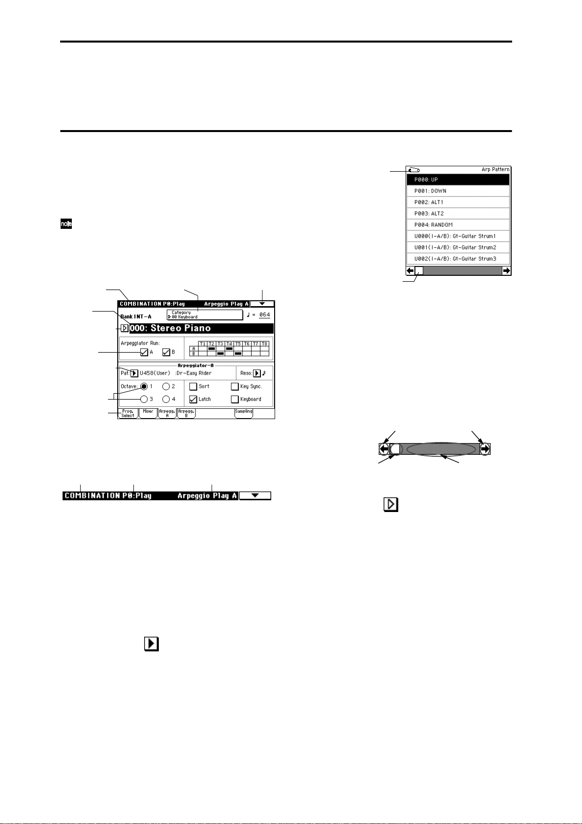
Using the arpeggiator in Program mode................ 29
Settings using controllers..................................... 29
Settings in the LCD screen................................... 30
Using the arpeggiator in Combination mode........ 31
Settings in the LCD screen................................... 31
Playing with the RPPR (Realtime Pattern Play/
Recording) function......................................33
Simple program editing.................................34
Performance Edit........................................................ 34
Realtime controls........................................................ 34
Simple combination editing............................35
An example of editing............................................... 35
Sampling (recording a sample)........................37
Sampling a vocal from a mic, and playing it as a
“one-shot” sample................................................. 37
Applying an insert effect to the audio input and
sampling the result ............................................... 39
Assigning a name to the sample or multisample.. 40
Saving sample data.................................................... 41
Converting a multisample into a program............. 41
Sampling and looping a drum phrase .................... 42
Resampling an arpeggiated phrase in Program
mode........................................................................ 45
Sample an arpeggiated drum phrase together with
an externally-input guitar.................................... 46
Producing a song.........................................49
Creating the basic song ............................................. 49
Naming the song and tracks..................................... 53
Saving the song........................................................... 54
Selecting and playing a program ..................... 22
Selecting a program....................................................22
Selecting and playing a combination ................ 24
Selecting a combination.............................................24
v
Page 6

Basic functions .................. 55
Saving data ...............................................55
Types of data that can be saved ............................... 55
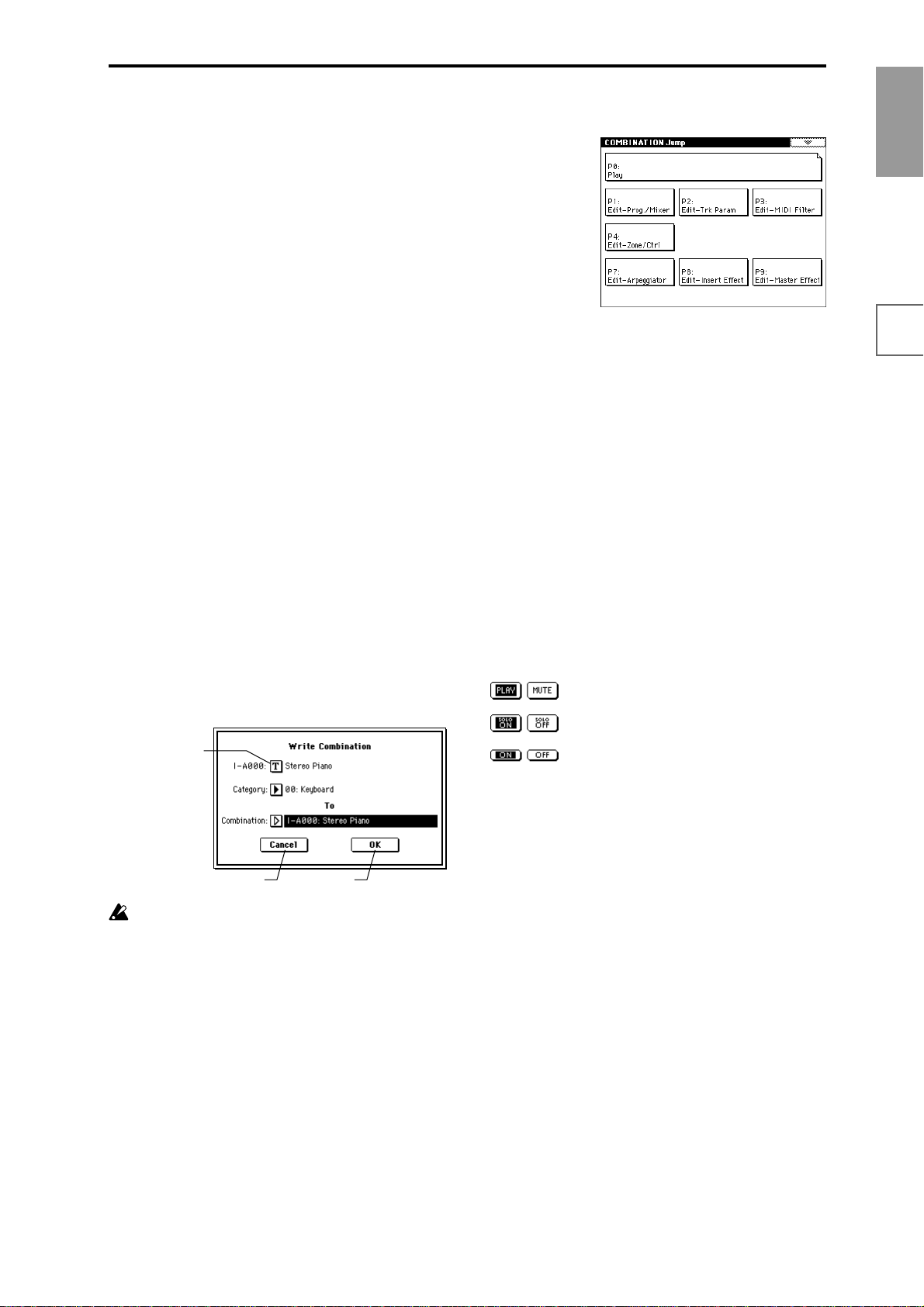
Writing to internal memory...................................... 56
Writing a program or combination.....................56
Writing global settings, user drum kits, and user
arpeggio patterns .................................................. 58
Saving on media......................................................... 59
Types of media that can be used.........................59
Formatting media..................................................60
How to save data................................................... 60
MIDI data dump......................................................... 62
Loading data and restoring the factory settings.....63
Loading data...............................................................63
Types of data that can be loaded ........................ 63
Loading data/Restoring the factory settings....63
Loading .PCG files and .SNG files from the floppy
disks included with the EXB-PCM series and
EXB-MOSS options ............................................... 65
Program settings.........................................67
How a program is organized.................................... 67
Basic program editing................................................ 67
Oscillator settings P1: Edit-Basic......................... 68
Pitch settings P2: Edit-Pitch................................. 70
Filter settings P3: Edit-Filter ................................ 71
Amplifier settings P4: Edit-Amp......................... 72
LFO settings P5: Edit-Common LFO.................. 74
Arpeggiator settings P7: Edit-Arpeggiator........ 74
Insert Effect settings P8: Edit-Insert Effect ........ 74
Master Effect settings P9: Edit-Master Effect....74
More about Alternate Modulation........................... 74
Combination settings....................................75
How a combination is organized............................. 75
Basic combination editing......................................... 75
Timbre 1–8 program, pan and volume
P1: Edit-Program/Mixer......................................76
Settings for status, MIDI channel, and pitch
parameters P2: Edit-Trk Param........................... 77
MIDI filter settings P3: Edit-MIDI Filter............ 78
Layer, split, and velocity switch settings/
Controller settings P4: Edit-Zone/Ctrl .............. 78
Arpeggiator settings P7: Edit-Arp......................79
Insert Effect settings P8: Edit-Insert FX.............. 79
Master Effect settings P9: Edit-Master FX ......... 79
Song editing methods.................................................88
1. Copying a song..................................................88
2. Naming a song ..................................................88
3. Setting the number of measures in the song.88
4. Changing the key
(transposing/modulating)...............................89
Creating and playing a Cue List...............................90
Converting a song..................................................92
Creating and recording RPPR (Realtime Pattern
Play/Record) ..........................................................92
Creating RPPR data...............................................92
RPPR playback.......................................................93
Realtime-recording an RPPR performance........94
Recording the sounds of a combination..................95
Caution and other functions in Sequencer mode...97
Sampling settings ....................................... 99
Features of sampling on the TRITON STUDIO......99
How Sampling mode is organized.........................100
Samples and Multisamples.................................101
Preparations for sampling .......................................102
1. Connecting an input device and making
settings..............................................................102
2. Setting the recording level (Recording Level
[dB]) ..................................................................103
3. Specifying the recording method (Recording
Setup/Sampling Setup) .................................104
4. Making settings for the sample to be recorded
(REC Sample Setup/Sampling Setup).........104
Sampling and editing in Sampling mode..............106
Creating multisample indexes and sampling..106
Applying an insert effect to a sample and
resampling it.........................................................107
Ripping..................................................................108
Loop settings.........................................................110
Sample (waveform data) editing.......................111
Multisample editing ............................................111
Converting a multisample to a program..........112
Using Time Slice to divide a sample, and playing
it in Sequencer mode...........................................112
Sampling in Program, Combination, or Sequencer
modes.....................................................................115
Record an external audio input source while a
song plays, and create event data at the same time
(In-Track Sampling function).............................115
Resampling the song playback to create a WAVE
file on the hard drive...........................................116
Input
Producing songs .........................................80
Features of the sequencer.......................................... 80
The structure of Sequencer mode ............................ 81
Songs.......................................................................81
Patterns...................................................................81
Cue List................................................................... 81
Preparations for recording........................................ 82
Recording methods.................................................... 83
Realtime recording on a track ............................. 83
Step recording........................................................ 86
Event Edit and Create Control Data...................86
Realtime-recording to a pattern..........................86
vi
Page 7

Creating an audio CD from WAVE files sampled to hard
disk .......................................................118
SMF (Standard MIDI File) playback .................120
The structure of Song Play mode........................... 120
Playing SMF data......................................................121
Playback using the Jukebox function ....................122
Saving a Jukebox list...........................................122
Playing along with SMF data..................................123
Settings for the entire TRITON STUDIO (Global
settings)..................................................124
Tuning to another instrument/Transposing........124
Adjusting the way in which velocity or after touch
will affect the volume or tone............................124
Bypassing the effects................................................124
Recalling the last-selected mode and page at power-
on ...........................................................................125
Specifying the function of the ASSIGNABLE Switch
and ASSIGNABLE Pedal.................................... 125
Creating original scales.......................................126
Drum kit settings .......................................127
About drum kits .......................................................127
Editing a drum kit ....................................................128
Arpeggiator settings ...................................130
Arpeggiator settings for a program....................... 130
Arpeggiator on/off ............................................. 130
Arpeggiator settings............................................130
Arpeggiator settings in Combination and Sequencer
modes....................................................................132
Arpeggiator on/off ............................................. 132
Arpeggiator settings............................................132
Creating an user arpeggio pattern.........................134
About user arpeggio patterns............................134
Editing a user arpeggio pattern......................... 134
Dual arpeggiator editing.........................................137
Synchronizing the arpeggiator...............................138
Synchronization between arpeggiators A
and B......................................................................138
Synchronization between the arpeggiators and
sequencer in Sequencer or Song Play mode....138
Synchronization with an external sequencer in
Program, Combination, or Sequencer modes . 138
Other functions ......................................... 145
Setting the function of [SW1] and [SW2].............. 145
Setting the B-mode functions of REALTIME
CONTROLS [1]–[4]............................................. 145
Adjusting the contrast (brightness) of the LCD
screen .................................................................... 145
Sounding a beep when the LCD screen is
pressed.................................................................. 146
Using the TRITON STUDIO as a data filer .......... 146
Setting the calendar function.................................. 146
Shortcuts.................................................................... 146
Appendices .....................147
Troubleshooting........................................ 147
Power supply............................................................ 147
LCD screen................................................................ 147
Audio input and output.......................................... 147
Program, Combination............................................ 149
Song............................................................................ 149
Sampling.................................................................... 149
Drum kits................................................................... 150
Arpeggiator............................................................... 150
Effects......................................................................... 150
MIDI........................................................................... 151
Media ......................................................................... 151
WAVE files................................................................ 152
Other .......................................................................... 152
Specifications and options............................ 153
Specifications ............................................................ 153
Options ...................................................................... 154
MIDI implementation chart........................... 155
Index .....................................................156
Effects settings..........................................139
Effects in each mode.................................................139
Routing settings and effect settings....................... 140
Effect settings for a program..............................140
Effect settings in Combination, Song, and Song
Play modes ...........................................................141
Effect settings in Sampling mode......................142
Effect settings for AUDIO INPUT.....................143
About dynamic modulation (Dmod).....................144
vii
Page 8

viii
Page 9

Introduction
Main features
Overview
The TRITON STUDIO is a music workstation/sampler
that features the
as its tone generator.
It provides high-quality preset multisamples/programs/
combinations and an effect section, and functions such as
sampling, sequencer, song play, dual polyphonic arpeggiator, RPPR, six audio outputs and can support up to six
audio inputs.
A rich array of controllers such as the joystick, ribbon controller, assignable switches [SW1] & [SW2], assignable/
preset knobs REALTIME CONTROLS [1]–[4], ARPEGGIATOR [TEMPO], [GATE], [VELOCITY] knobs, and a
variety of optional pedals can be used to modify the
sound while you play.
You can further expand the potential of the TRITON STUDIO by installing options such as a MOSS tone generator,
PCM expansion boards, additional sampling memory,
ADAT digital output, mLAN interface board, and a CDR/RW drive. (
The TRITON STUDIO music workstation is a powerful
tool for music production or live performance.
HI (Hyper Integrated) synthesis system
The HI (Hyper Integrated) synthesis system is a PCM tone
generator system with full digital signal processing that
guarantees pristine sound, and featuring enormous flexibility in musical expression, modulation, and effect routing.
Tone generator section:
• 48 Mbytes of preset PCM ROM contains 429
multisamples and 417 drumsamples.
By installing optional EXB-PCM series PCM expansion
boards (16 Mbytes PCM ROM), you can expand the
PCM data to a maximum of 112 Mbytes.
• 16 Mbytes of RAM is standard (expandable to a
maximum of 96 Mbytes). Samples or multisamples
that you sampled or resampled in Sampling mode or
other modes (or that you loaded in Disk mode) can be
used as sound sources.
• The sampling frequency is 48 kHz, and the maximum
polyphony is 60 voices (a maximum of 120 voices can
be used depending on the PCM sounds you use).
☞
p.15
Filter/synthesis section:
• Either a 24 dB/oct Resonant Low Pass or a 12 dB/oct
Low Pass & High Pass type filter can be used. A wide
variety of filter effects can be achieved, from active
sounds with aggressive resonance to subtle tones
using a high pass filter.
• A broad range of editing parameters gives you precise
control over every aspect of the sound.
HI (Hyper Integrated) synthesis system
☞
PG p.286)
Effect section:
• Five insert effects (stereo-in/stereo-out), two master
effects (mono-in/stereo-out), and a three-band master
EQ (stereo-in/stereo-out) can all be used
simultaneously. You can select and edit any of 102
types of effect algorithms.
• The effect routing is highly flexible. Effects can be
routed freely to the individual inputs and outputs.
Alternate Modulation and Effect Dynamic Modulation:
• The synthesis section (filter etc.) provides Alternate
Modulation capabilities, and the effect section
provides Effect Dynamic Modulation. This allows you
to freely apply modulation to parameters that affect
the pitch, filter, amp, EG, LFO, and effects etc.
• LFO, delay time and other effect parameters can be
synchronized to an external MIDI clock. You can also
synchronize sounds and effects to the tempo of the
internal sequencer or the arpeggiator.
Programs and combinations
• In preset ROM, the TRITON STUDIO provides 1,536
user programs, and 256 programs + 9 drumsets for
GM2 compatibility. When shipped from the factory, it
contains high-quality preload programs (512) that
cover a wide range of musical needs.
The 1,536 user programs can be modified by adjusting
the numerous editing parameters, the effects and the
arpeggiator, to create your own original programs.
When the EXB-MOSS option is installed, 128 programs
for use with the Korg MOSS tone generator will also be
available.
• The TRITON STUDIO provides 144 user drum kits as
well as 9 ROM drum kits compatible with GM2. The
factory settings contain 20 preloaded drum kits that
cover a wide range of musical styles.
You can create your own drum kits by assigning each
key to any one of the 417 drum samples or to an original sample that you sampled or loaded in from media.
For the sound assigned to each key , you can make filter
and amp settings, and even route the sound to effects
or individual audio outputs.
• A multisample or sample that was sampled or
resampled in Sampling mode or other modes (or
loaded in from media using the Disk mode) can be
easily used to create a program. These programs can
also be used in a combination or song. Samples can
also be used as drum instruments in a drum kit.
• The TRITON STUDIO provides 1,536 user
combinations. With the factory settings, these contain
a wide variety of preload combinations (512).
A combination allows you to use layers, splits, or
velocity switches to combine up to eight programs
together with effects and two arpeggiators, in order to
create complex sounds that could not be produced by a
single program. You can also make settings that
include external tone generators.
Introduction
FeaturesFront &
rear panel
LCD screenConnectionsBasics
1
Page 10

2
×
Sampling
The TRITON STUDIO features an Open Sampling System
that allows sampling and resampling to be performed not
only in Sampling mode, but also in Program, Combination, or Sequencer modes.
You can perform 48 kHz 16-bit linear mono or stereo sampling; 16 Mbytes of sample memory (RAM) as well as a
hard drive are factory-installed. (For the capacity of the
hard drive, refer to p.154.)
Sample memory (RAM) of 16 Mbytes is factory-installed,
allowing approximately 2 minutes 54 seconds of mono
sampling (or approximately 1 minute 27 seconds of stereo
sampling). Sample memory can be expanded to a maximum of 96 Mbytes, which allows you to record up to six
samples of approximately 2 minutes 54 seconds each
(mono) or approximately 1 minute 27 seconds each (stereo), for a total 17 minutes 28 seconds of sampling time.
hard drive lets you record up to 80 minutes as a sin-
The
gle sample file in either mono or stereo (monaural:
approximately 440 Mbytes, stereo: approximately 879
Mbytes). This will create a WAVE file. (In order to play a
hard disk sample from the TRITON STUDIO’s keyboard,
it must be able to be loaded into the sampling memory
(RAM). Sample files of up to 16 Mbytes (mono) or 32
Mbytes (stereo) can be loaded into RAM.)
For more on the sampling features of the TRITON STUDIO (
☞
p.99).
Sequencer
A sophisticated 16-track MIDI sequencer is built in. The
sequencer can be used in conjunction with other functions
such as the dual arpeggiator and RPPR, making it an even
more powerful music production tool than a stand-alone
sequencer.
In addition, you can sample while listening to sequencer
tracks play back – just as if you were recording an audio
track (In-Track Sampling).
☞
For more on the TRITON STUDIO’s sequencer (
p.80).
Song Play
In Song Play mode, SMF (Standard MIDI File) songs can
be played back directly from floppy disk or other media.
You can also play the keyboard along with the SMF playback. You can play along on the keyboard as you listen to
the SMF playback, and even play the arpeggiator in sync
with the playback tempo of the SMF.
• Formats 0 and 1 are supported.
• A jukebox function lets you edit the order in which
songs are played back.
Dual polyphonic arpeggiator
• Five preset arpeggio patterns (UP, DOWN, ALT1
ALT2, RANDOM) and 507 user arpeggio patterns are
provided. With the factory settings, these contain a
wide variety of preload user patterns (367).
In addition to providing conventional arpeggiator
functions, the polyphonic arpeggiator of the TRITON
STUDIO can respond to the pitches or timing at which
you play the keyboard, and produce a diverse range of
chords or phrases. This can be used to play a variety of
drum phrases (using the “Fixed Note Mode” that is
ideal for drums), bass phrases, or guitar and keyboard
backing riffs. The arpeggiator is also effective for use
with subtly moving pads, synth sounds, or sound
effects.
In Combination mode, Sequencer mode, and Song Play
mode, the TRITON STUDIO provides dual arpeggiators that can simultaneously play two arpeggio patterns. You can apply separate arpeggio patterns to
drum and bass programs, or use keyboard splits or
velocity to switch between arpeggio patterns for an
even more dynamic performance.
RPPR
The TRITON STUDIO features Korg’s RPPR (Realtime
Pattern Play/Recording) function.
In Sequencer mode, this function allows you to assign preset patterns or user patterns (with a specified playback
track) to individual notes of the keyboard, and playback
that pattern in realtime simply by pressing the assigned
note. Numerous preset patterns, including patterns ideal
for drum tracks, are built into the internal memory.
6-channel audio input/6-channel audio output
• Both analog (2 channel) and digital (2 channel) audio
inputs are standard, allowing you to record stereo
samples. (If the EXB-mLAN option is installed, two
more input channels will be added.)
The analog inputs have a MIC/LINE level select
switch and a level knob, accommodating a wide range
of audio sources from mic level to line level.
The digital inputs support S/P DIF format.
Audio inputs can also be routed to the effects. You can
apply effects while sampling, and use the TRITON
STUDIO as a 6-in/6-out effect processor or even create
a vocoder effect in conjunction with internal sounds.
• 6 channels of audio output are standard: four
individual audio outputs in addition to the L/MONO
and R main stereo audio outputs. Oscillators, drums,
timbres/tracks, and the insert effect outputs can all be
freely routed to any output.
As analog outputs, the TRITON STUDIO provides
AUDIO OUTPUT (MAIN) L/MONO, R, and (INDIVIDUAL) 1, 2, 3, and 4.
As digital output, you can use S/P DIF (2 channels: L/
MONO and R), ADAT (when the EXB-DI option is
installed), and mLAN (6 channels: when the EXB-mLAN
option is installed).
• S/P DIF input and output support 48 kHz/96 kHz
sampling frequencies.
You can interface directly to a 96 kHz sampling frequency digital recording system.
TouchView user interface
The TRITON STUDIO uses a TouchView user interface
that lets you operate the instrument directly by touching a
large 320
in ease of operation and user friendliness. When selecting
programs, combinations, multisamples, drumsamples, or
effects in the LCD screen, you can also view and select by
categories such as types of instrument.
240 pixel LCD screen, for a revolutionary leap
CD-RW drive
When the CDRW-1 (CD-R/RW drive) option is installed,
you can create original CD’s, back up your data, or play
back and sample from audio CD’s without the need to
connect any external equipment.
Page 11
Front and rear panel
3
Introduction
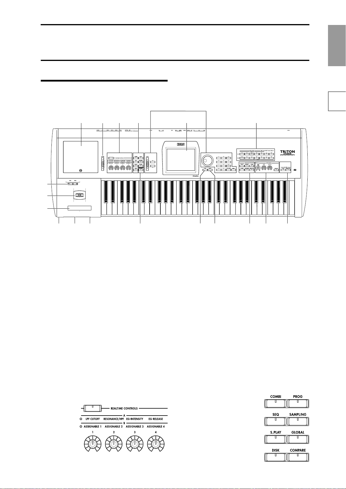
Front panel
16
1
2
3
18 1917
1. [SW1] key, [SW2] key
These keys are on/off switches, their function can be
assigned in Program, Combination, Sequencer, Song Play,
and Sampling modes. When on, the LED will light
☞
p.25).
(
2. Joystick
This controls pitch and modulation.
Move the joystick up/down and left/right (+Y, –Y, –X,
☞
+X) to vary the effect (
Various program parameters and effect parameters will
determine what is being controlled by the joystick.
3. Ribbon controller
Slide your finger to the left or right on this ribbon controller to control the pitch or modulation (☞p.26).
Various program parameters and effect parameters will
determine what is controlled by the ribbon controller.
p.25).
5
4
69
7 10 11
8
12
13 1514
Use the [REALTIME CONTROLS] key to select A or B
mode for the realtime controllers, and use knobs [1]–[4] to
control the tone, effects, and MIDI control changes etc. in
realtime (☞p.26).
[REALTIME CONTROLS] key
This key selects either A or B mode for the realtime controllers. The selected mode will light.
[1] knob, [2] knob, [3] knob, [4] knob
In A mode, the function of each knob is fixed. [1] is the
low pass filter cutoff frequency, [2] is the filter resonance
level or the cutoff frequency of the high pass filter, [3] is
the filter EG intensity, and [4] is the filter/amp release
time.
In B mode, each knob will control the function that was
assigned to it in the Program, Combination, Sequencer,
Song Play, or Sampling modes.
FeaturesFront &
rear panel
LCD screenConnectionsBasics
4. [VOLUME] slider
This adjusts the volume that is output from the AUDIO
OUTPUT (MAIN) L/MONO, R jacks and the headphone
jack.
5. REALTIME CONTROLS
6. Mode keys
Use these keys to enter the desired mode.
When you press a key, the LED will light, and you will
enter the mode whose key you pressed (☞p.16).
[COMBI] key
Combination mode will be selected.
[PROG] key
Program mode will be selected.
[SEQ] key
Sequencer mode will be selected.
Page 12
[SAMPLING] key
Sampling mode will be selected.
[S.PLAY] key
Song Play mode will be selected.
[GLOBAL] key
Global mode will be selected.
[DISK] key
Disk mode will be selected.
7. [COMPARE] key
Use this key when you wish to compare the sound of the
program or combination that you are currently editing
with the un-edited sound already in memory . You can also
use this key to make “before and after” comparisons
when recording or editing in Sequencer mode (☞p.17).
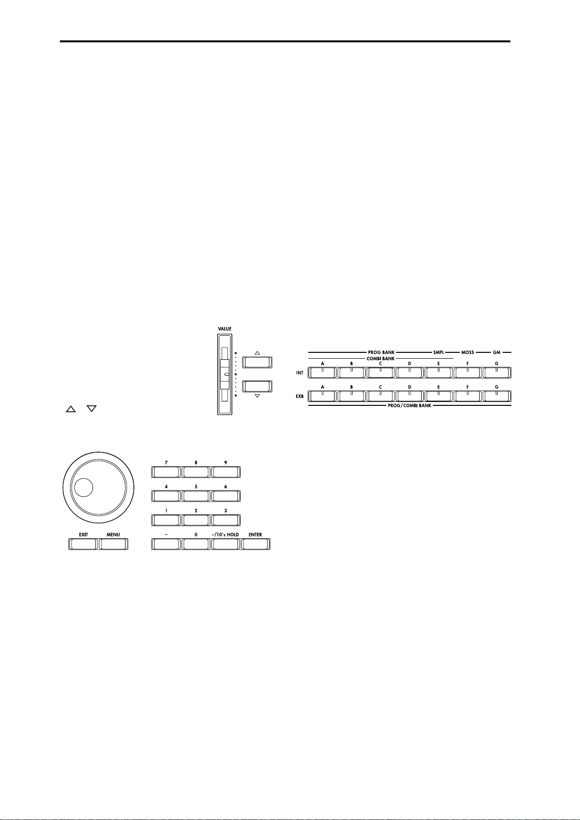
8. VALUE controllers
The following V ALUE controllers ar e used to set the value
of the selected parameter (☞p.17).
[VALUE] slider
Use this to modify the value of a parameter. This controller is convenient when
you wish to make large changes in the
value.
This slider can also be used as a modulation source.
9. LCD screen
The TRITON STUDIO features a Touch-View system that
uses a touch-panel LCD screen.
By touching on objects that are shown in the LCD screen,
you can select pages, tabs, and parameters, and set values
(☞p.8).
10. [EXIT] key
When a dialog box is open, this key will cancel the settings made in the dialog box and close the dialog box (corresponds to the Cancel button). If a popup menu or page
menu is open, pressing [EXIT] will close the menu.
When in P (page) 1–9 of each mode, pressing the [EXIT]
key will move to P (page) 0 of that mode.
11. [MENU] key
Use this key to move between pages. When you press the
[MENU] key, a list of the pages in the mode will appear in
the LCD screen. Press the desired page, and you will
move to that page. You can also move to a page by holding down the [MENU] key and pressing the corresponding numeric key [0]–[9] (☞p.16).
12. BANK keys
These keys are used to switch the program/combination
bank.
[ ][ ] keys
These are used to increase or decrease the parameter
value in steps of one. It is convenient to use these to make
fine adjustments.
[VALUE] dial
Use this dial to modify the value of the parameter.
Numeric keys [0] – [9], [ENTER] key, [–] key
[./10’s HOLD] key
Use these keys to numerically input a parameter value.
Use numeric keys [0]–[9], the [–] key, and the [./10’s
HOLD] key to enter the value, and press the [ENTER] key
to confirm it. The [./10’s HOLD] key lets you input a
value with a decimal point. The [–] key inverts the sign
(+/–) of the parameter value.
The [./10’s HOLD] key is also used when you wish to
hold the 10’s place while selecting programs or combinations.
By holding down the [ENTER] key and pressing a
numeric key [0]–[9], you can select up to ten page menu
commands in the current page.
PROG BANK:
[INT-A], [INT-B], [INT-C], [INT-D], [INT-E] (SMPL),
[INT-F] (MOSS), [INT-G] (GM), [EXB-A], [EXB-B],
[EXB-C], [EXB-D], [EXB-E], [EXB-F], [EXB-G]
COMBI BANK:
[INT-A], [INT-B], [INT-C], [INT-D], [INT-E], [EXB-A],
[EXB-B], [EXB-C], [EXB-D], [EXB-E], [EXB-F], [EXB-G]
In Program mode, these keys select the program bank.
In Combination mode, these keys select the combination
bank. When assigning a program to the various timbres in
a combination, then these keys will select the program
bank. In this case, the LED of the program bank selected
for the timbre will light.
In Sequencer and Song Play modes when the edit cell
(highlighted area) is located at the program of each track,
these keys select the program bank just as in Combination
mode.
If you repeatedly press the [INT-G] key when selecting a
program, the bank selection will cycle through all of the
GM(2) banks and drum banks in the order of G, g(1), g(2)–
g(8), g(9), g(d), G ... each time you press the key.
The [INT-F] bank can be selected in Program mode only if
the EXB-MOSS option is installed.
4
Page 13
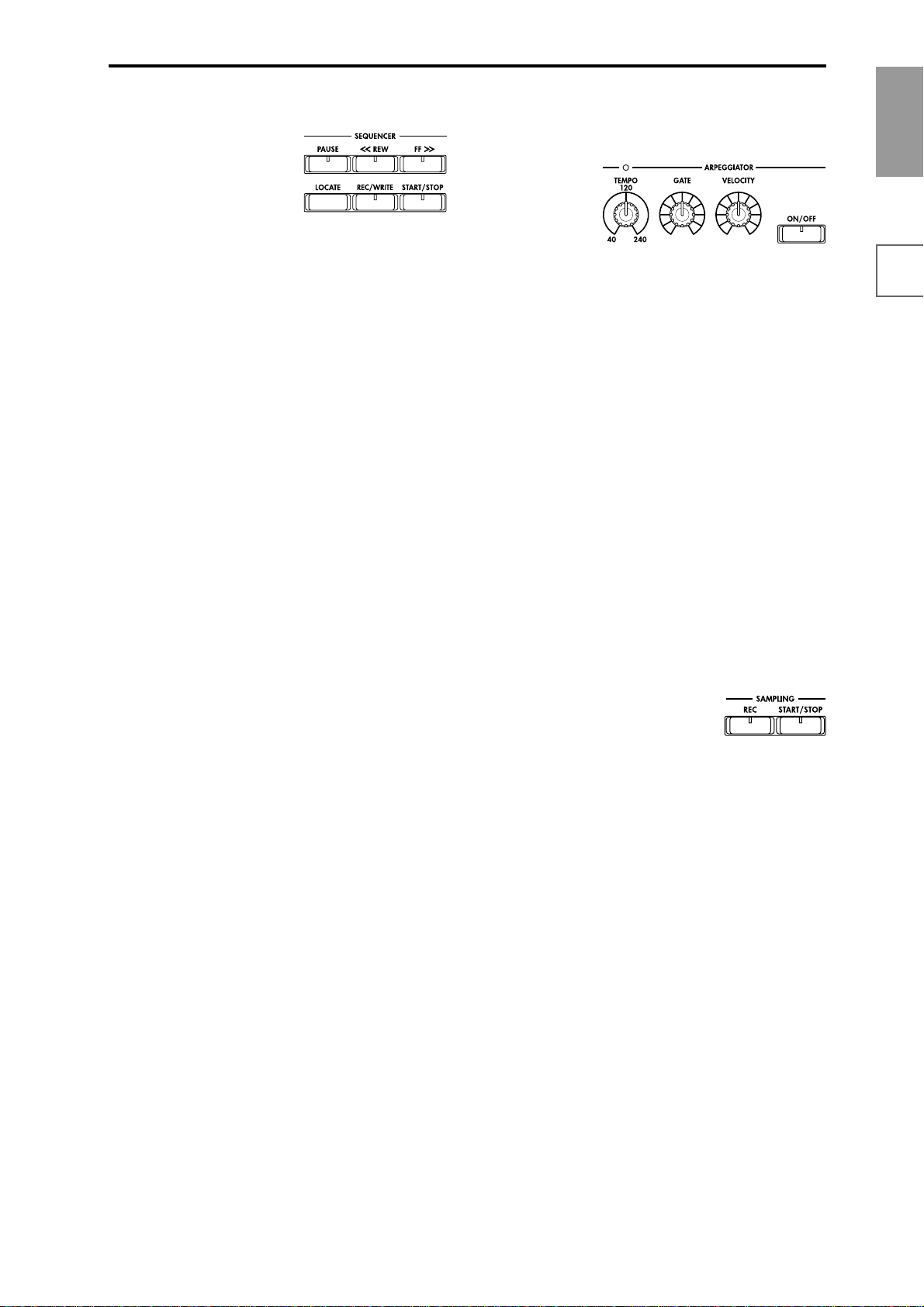
13. SEQUENCER
[PAUSE] key
In Sequencer mode, this key pauses the playback of the
song or cue list. In Song Play mode, this key pauses SMF
playback. When paused, the LED will light. Press
[PAUSE] once again to resume playback; the LED will
turn off.
[<<REW] key
In Sequencer mode, this key will rewind the song or cue
list. When you press and hold this key, the LED will light,
and the playback will rewind. (This key will not function
during recording.)
[FF>>] key
In Sequencer mode, this key will fast-forward the song or
cue list. When you press and hold this key, the LED will
light, and the playback will fast-forward. (This key will
not function during recording.)
[LOCATE] key
In Sequencer mode, this key will advance or rewind the
song or cue list playback to a specified point. In Song Play
mode, this key returns the playback location of the SMF to
a specified point.
SEQUENCER [REC/WRITE] key
In Sequencer mode, pressing this key will make the LED
light, and if you then press the SEQUENCER
STOP] key, recording will begin (☞p.84).
In Program, Combination and Global modes, pressing this
key will open a dialog box, and if you then press the OK
button, the edited contents will be written (☞p.57, 59).
[START/
SEQUENCER [START/STOP] key
This is the start/stop key for song or cue list recording
and playback in Sequencer mode, and SMF playback in
Song Play mode. (During recording and playback, the
LED will blink at the current tempo.)
These keys are also used to play an audio CD in the
CDRW-1 option or in a SCSI-connected CD-R/RW drive.
SEQUENCER [START/STOP] key : Play/Stop
[FF>>] key : Fast-forward
[<<REW] key : Rewind
[PAUSE] key : Pause
[LOCATE] key : Return to the beginning of
the track
14. ARPEGGIATOR
These knobs control the performance of the arpeggiator in
realtime (☞p.29).
[TEMPO] knob
This adjusts the base tempo of the arpeggiator and
sequencer. The LED will blink at quarter-note intervals of
the current tempo.
[GATE] knob
This adjusts the gate time (note duration) of the arpeggiated notes. At the center position (12 o’clock), the gate
time will be the same as the “Gate” parameter of the
arpeggiator. Rotating the knob toward the left will shorten
the gate time, and rotating it toward the right will
lengthen the gate time.
[VELOCITY] knob
This adjusts the velocity (playing strength) of the arpeggiated notes. At the center position (12 o’clock), the velocity
will be the same as the “Velocity” parameter of the arpeggiator. Rotating the knob toward the left will decrease the
velocity, and rotating it toward the right will increase the
velocity.
[ON/OFF] key
This switches the Arpeggiator function on/off. When on,
the LED will light.
15. SAMPLING
SAMPLING [REC] key
In Sampling, Program, Combination, and Sequencer
modes, pressing this key will make the LED light, and
when you continue by pressing the SAMPLING [START/
STOP] key, sampling will either begin or you will enter
the sample-ready mode. (☞p.37)
SAMPLING [START/STOP] key
In Sampling, Program, Combination, and Sequencer
modes, pressing this key after pressing the SAMPLING
[REC] key will either cause sampling to begin, or it will
access the sample-ready mode.
In the Sampling P1: Sample Edit page, pressing this key
will sound the selected sample.
This key is also used to play back a WAVE file from the
internal hard disk. This function can be used in the directory window of various Disk mode pages, in the Disk
mode Make Audio CD page, and in the “Select Directory”
page menu dialog box of the Program, Combination,
Sequencer, and Sampling modes.
Introduction
FeaturesFront &
rear panel
LCD screenConnectionsBasics
16. EXB-PCM/sample memory (RAM) slot cover
Open this cover to install EXB-PCM option boards, or to
install SIMMs to increase the sampling memory (RAM).
Up to seven EXB-PCM option boards can be installed, and
up to three SIMM sampling memory (RAM) boards can be
installed. (☞PG p.286)
5
Page 14
18 1917
17. Headphone jack
A set of headphones can be connected here (stereo 1/4"
jack).
This allows stereo monitoring of the same signal as the
OUTPUT L/MONO and R jacks.
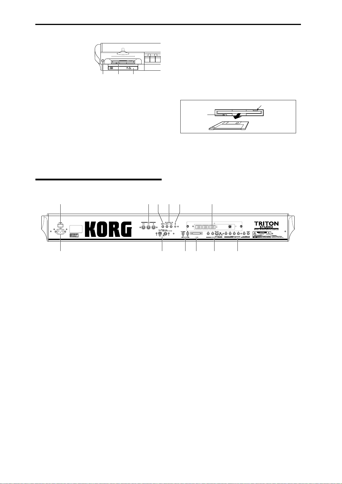
18. Floppy disk drive
3.5 inch 2DD (double-side double-density) or 2HD (double-side high-density) floppy disks can be inserted here,
allowing you to save your edited data, or to load factoryset data, SMF data, or multisample/sample data, etc...
Rear panel
For details on handling floppy disks, refer to “Cautions
when handling floppy disks” (☞p.62).
Eject button
To remove a floppy disk, make sure that the disk access
indicator is dark, and then press this button. If the disk is
not ejected when you press this button, do not attempt to
forcibly remove the disk, but contact your Korg distributor.
Eject button
Disk access
indicator
19. CDRW-1 drive bay
The CDRW-1 (CD-R/RW drive) option can be installed in
this bay. (☞PG p.286)
2
7 9810 12
1
1. AC power supply connector
Connect the included power supply cable here.
After connecting the power supply cable to the TRITON
STUDIO, connect the other end to an AC outlet (☞p.11).
2. [POWER] switch
This switch turns the power on/off (☞p.19).
3. AUDIO OUTPUT
Connect these outputs to the input jacks of your amp or
mixer. In addition to the L/MONO and R main stereo
audio outputs, the TRITON STUDIO provides four individual audio outputs. The sound from each oscillator,
drum, timbre/track, or insert effect can be freely routed to
any output (☞p.139–).
(MAIN) L/MONO, R
These are unbalanced phone jacks.
These are the main audio output jacks. By setting “Bus
Select” to L/R, the output from an oscillator, an insert
effect, an individual drum part, or the metronome can be
output to the (MAIN) L/MONO and R jacks.
When making connections in stereo, use L/MONO and R.
When making connections in mono, use the L/MONO
jack.
(INDIVIDUAL) 1, 2, 3, 4
These are unbalanced phone jacks.
These are individual (independent) audio output jacks. By
setting the “Bus Select” to 1, 2, 3, 4, 1/2, or 3/4, an oscilla-
345 611
tor, an insert ef fect, an individual drum part, or the metronome etc. can be assigned to be output from the
(INDIVIDUAL) 1, 2, 3, 4, jacks.
The output from the 1, 2, 3, 4 jacks is not affected by the
[VOLUME] slider.
4. AUDIO INPUT
These two audio inputs are used when recording a mono/
stereo sample from a mic or external audio source
(☞p.37), or when applying the TRITON STUDIO’s internal effects to an external audio source (☞p.143).
The MIC/LINE level select switch ([MIC/LINE] switch)
and the level adjustment knob ([LEVEL] knob) allow you
to use a wide range of external audio sources, ranging
from mic level to line level.
AUDIO INPUT 1/2 jacks
These are unbalanced phone jacks.
[LEVEL] knob
This adjusts the input level of the AUDIO INPUT 1/2
jacks.
[MIC/LINE] switch
This switches the input level of the AUDIO INPUT 1/2
jacks.
6
Page 15

5. S/P DIF
OUT(MAIN) jack
This is an optical type S/P DIF format (IEC60958, EIAJ
CP-1201) digital output jack.
It outputs a digital version of the same audio signal as the
AUDIO OUTPUT (MAIN) L/MONO and R jacks, at sampling rates of 48 kHz or 96 kHz (☞PG p.138).
Use an optical cable to connect this to the optical digital
input jack of a DAT or MD, etc.
The [VOLUME] slider does not adjust the output level of
this jack.
IN jack
This is an optical S/P DIF format (IEC 60958, EIAJ CP-
1201) digital input jack.
Digital audio at a sample rate of 48 kHz or 96 kHz can be
input here. 96 kHz audio will be converted to 48 kHz.
(☞PG p.138)
Use an optical cable to connect this jack to the optical digital output jack of a DAT or other device.
6. SCSI connector
This is a D-sub half-pitch 50 pin SCSI connector.
An external hard disk drive can be connected here and
used to sample or to save/load data in the same way as
the internal hard disk drive. A CD-R/RW can also be connected here to create an audio CD or to save/load data.
(☞p.59, 118)
7. MIDI
MIDI THRU connector
Musical data and sound settings etc. that are received at
the MIDI IN connector are re-transmitted without change
from the MIDI THRU connector.
You can use this to connect multiple MIDI devices (☞PG
p.258).
MIDI OUT connector
Musical data and sound settings etc. are transmitted from
this connector.
Use this to control another MIDI device connected via this
port to the TRITON STUDIO (☞PG p.258).
MIDI IN connector
Musical data and sound settings etc. are received at this
connector.
Use this to play the TRITON STUDIO from another MIDI
device connected to this port (☞PG p.258).
8. DAMPER jack
An optional switch-type pedal such as the Korg DS-1H
damper pedal can be connected here.
If a DS-1H is connected, it will function as a half-damper
pedal. If another switch-type pedal is connected, it will
function as a damper switch. In order to ensure that the
pedal functions correctly, please adjust the polarity and
the half-damper sensitivity (☞p.11, PG p.137, 146).
9. ASSIGNABLE
SWITCH jack
An optional on/off foot switch such as the Korg PS-1 foot
switch can be connected here (☞p.11).
Its function can be assigned in Global mode, allowing you
to use the foot switch as a modulation controller, to select
programs or combinations, or to start/stop the sequencer
(☞p.125).
PEDAL jack
An optional Korg EXP-2 or XVP-10 expression pedal can
be connected here (☞p.11).
Its function can be assigned in Global mode, allowing you
to use the pedal to control the volume etc. (☞p.124)
10. [Contrast adjustment] knob
This adjusts the contrast of the LCD screen.
The optimal setting will depend on the height or angle
from which you view the screen display, so please adjust
as necessary.
11. EXB-DI (option)
OUT jack
This is an ADAT optical format digital output connector.
It outputs the six channels of the TRITON STUDIO’s
AUDIO OUTPUT jacks (MAIN) L/MONO, R, (INDIVIDUAL) 1, 2, 3, 4 (analog audio outputs) as digital audio
with a sampling rate of 48 kHz. These signals are output
as channels 1 through 6 of the ADAT optical format.
By connecting this to the DIGITAL IN jack of an ADAT
Optical format compatible mixer, amp, or recorder, you
can output the audio signal of the TRITON STUDIO in
digital form. Use an optical cable made by the Alesis Corporation or an optical cable for CD/DAT (both sold separately) to make this connection (☞p.11, PG p.286, 300).
The [VOLUME] slider does not adjust the output level of
this connector.
48 kHz WORD CLOCK IN jack
Connect this to the WORD CLOCK OUT jack of an ADAT
Optical format compatible mixer or remote controller. Use
this when you want the connected device to be the word
clock master and the TRITON STUDIO to be the word
clock slave for synchronization. Use an BNC coax cable
made by the Alesis Corporation or a video BNC cable
(both sold separately) to make this connection.
12. EXB-mLAN (option)
A special cable is used to connect mLAN-compatible
devices or computers. (☞p.12, PG p.286)
mLAN (IEEE 1394) 1, 2, 3 jacks
SERIAL I/O connector
For details refer to the manual included with the EXBmLAN option.
What is mLAN?
mLAN is a new standard for musical instruments that uses the
general-purpose IEEE 1394 (“FireWire”) interface (a general-purpose interface with a wide range of uses including current and digital AV devices) with a special transmission protocol for musical
data. It allows high quality digital audio and MIDI data to be simultaneously transmitted and received over a single cable. At a transmission speed of 200 Mbps, approximately 100 channels of audio
data or 256 ports of MIDI data (i.e., 16 channels x 256 connectors)
can be transmitted and received over a single cable.
mLAN provides unprecedented flexibility, allowing you to daisychain up to 63 devices, and even to reconfigure the input and output connections between devices without actually disconnecting
the mLAN cable. Even sophisticated setups in the studio or on
stage are made easy by mLAN.
Introduction
FeaturesFront &
rear panel
LCD screenConnectionsBasics
7
Page 16
Names and functions of objects in the LCD
screen
The TRITON STUDIOuses Korg’s TouchView graphical
user interface.
By touching on objects displayed in the LCD screen, you
can select pages, set parameter values, rename programs
and combinations, write data, and perform many other
operations.
References in the TRITON STUDIO’s owner’s manual to the “... button” or “... tab” refer to objects displayed on the LCD screen. References to the “[...]
key,” “[...] knob,” “[...] dial,” or “[...] slider” refer to
controls on the front or rear panel of the TRITON
STUDIO.
a: Current page
b: Edit cell
d: Popup button (2)
f: Check box
c: Popup button (1)
g: Radio buttons
h: Tab
i: Page menu buttone: (category) Popup button
a: Current page
This indicates the selected page within the current mode.
From the left, this shows the mode name, page number,
and page name.
Mode name Page namePage number
* Popup menu
Pin
Scroll bar
Pin
This switches the popup menu display between locked
and unlocked.
When locked, the pin will be shown closed, and the
popup menu will remain displayed even after you press a
parameter value. When unlocked, the pin will be shown
opened, and the popup menu will close immediately
when you press a parameter value.
Scroll bar
Use this when you wish to see parameter values that
extend beyond what can be displayed in the screen at one
time.
Press here to scroll to left or right.
Press here and slide to left
or right to scroll to the
desired location.
Press here to scroll to
the corresponding
location.
b: Edit cell
When you press a parameter in the LCD screen, the
parameter or parameter value will sometimes be highlighted (displayed in inverse video). This is called the edit
cell, and the highlighted item will be subject to editing.
The parameter value of the edit cell can be modified using
the VALUE controllers (☞p.17) or by using a popup button in the LCD screen. For parameters that accept a note
number or a velocity value, you can also hold down the
[ENTER] key and play a note on the keyboard to enter the
note number or velocity value.
c: Popup button (1)
When this button is pressed, a popup menu will appear,
showing the parameter values that are available for selection.
To input the parameter value, press the desired value in
the popup menu.
When a popup menu is displayed, operating a VALUE
controller (☞p.17) will close the popup menu. If the
popup menu is unlocked (☞“Pin”), it will close if you
touch a location outside the popup menu.
d: Popup button (2)
When you press this button, a tabbed popup menu will
appear, allowing you to perform the following selections.
• “Bank/Program Select,” “Bank/Combination Select”:
Select programs or combinations by bank
• “Multisample Select”: Select a multisample for a
program oscillator by category (ROM multisamples
only)
• “Category/Effect Select”: Select an insert effect or
master effect by category
To close the tabbed popup menu, press the OK button
or Cancel button.
e: (Category) popup button
When you press this button, a tabbed popup menu will
appear, allowing you to perform the following selections.
• “Category/Program Select,” “Category/Combination
Select”: Select programs or combinations by category
To close the tabbed popup menu, press the OK button
or Cancel button.
8
Page 17
f: Check box
Each time you press a check box, a check mark will be
added or removed.
When checked, the parameter will function; when
unchecked, the parameter will not function.
* Page jump menu
Introduction
g: Radio buttons
Press a radio button to select one value from two or more
choices.
h: Tab
Press the tab to select a page.
i: Page menu button
When this button is pressed, a list of page menu commands will appear.
The page menu commands that appear will depend on
the currently selected page.
You can also select up to ten page menu commands by
holding down the [ENTER] key and pressing a numeric
key [0]–[9].
The page menu will close when you press the LCD screen
at a location other than the page menu, or when you press
the [EXIT] key.
* Dialog box
The dialog box that appears will depend on the currently
selected page menu command.
When selecting a program or combination number in a
dialog box, use the VALUE controllers (☞p.17) to input
the number.
T o execute, pr ess the OK button. To cancel without executing, press the Cancel button. (The operation will occur
when you press and release the button.) The dialog box
will close. The [EXIT] key corresponds to the Cancel button, Done button, and Exit button.
Text edit button
In Combination, Program, Sequencer, Sampling, Song
Play, or Global modes, you can press the front panel
[MENU] key to view a list of the pages in that mode. (As a
reminder, the page you were in before you pressed the
[MENU] key will have its top right corner bent over.) By
pressing one of the pages shown, you can move to that
page. (You can also move to the corresponding page by
pressing a numeric key [0]–[9].)
When you press the [EXIT] key, P0 will be displayed.
* Other objects
To modify the parameter value of an object shaped like a
slider or knob, press it to move the edit cell to that object,
and use the VALUE controllers to modify the value. In
addition, there are also buttons similar to the OK button
and Cancel button explained in “* dialog box” which execute an operation when they are pressed and released,
such as the Done button, Copy button, and Insert button.
Toggle buttons
This type of button will change its function or switch on/
off each time it is pressed.
PLAY/MUTE/REC button in Sequencer
and Song Play mode
SOLO ON/OFF button in Sequencer and
Song Play mode
ON/OFF button for Insert Effect and Master Effect
FeaturesFront &
rear panel
LCD screenConnectionsBasics
Cancel button OK button
After some commands are executed, the previouslylocked page menu will be unlocked automatically,
and the page menu will be closed.
* Text edit button
When you press this button, a text edit dialog box will
appear.
Here you can rename text (such as the name of a program,
combination, or song etc.) (☞p.40, 57).
9
Page 18
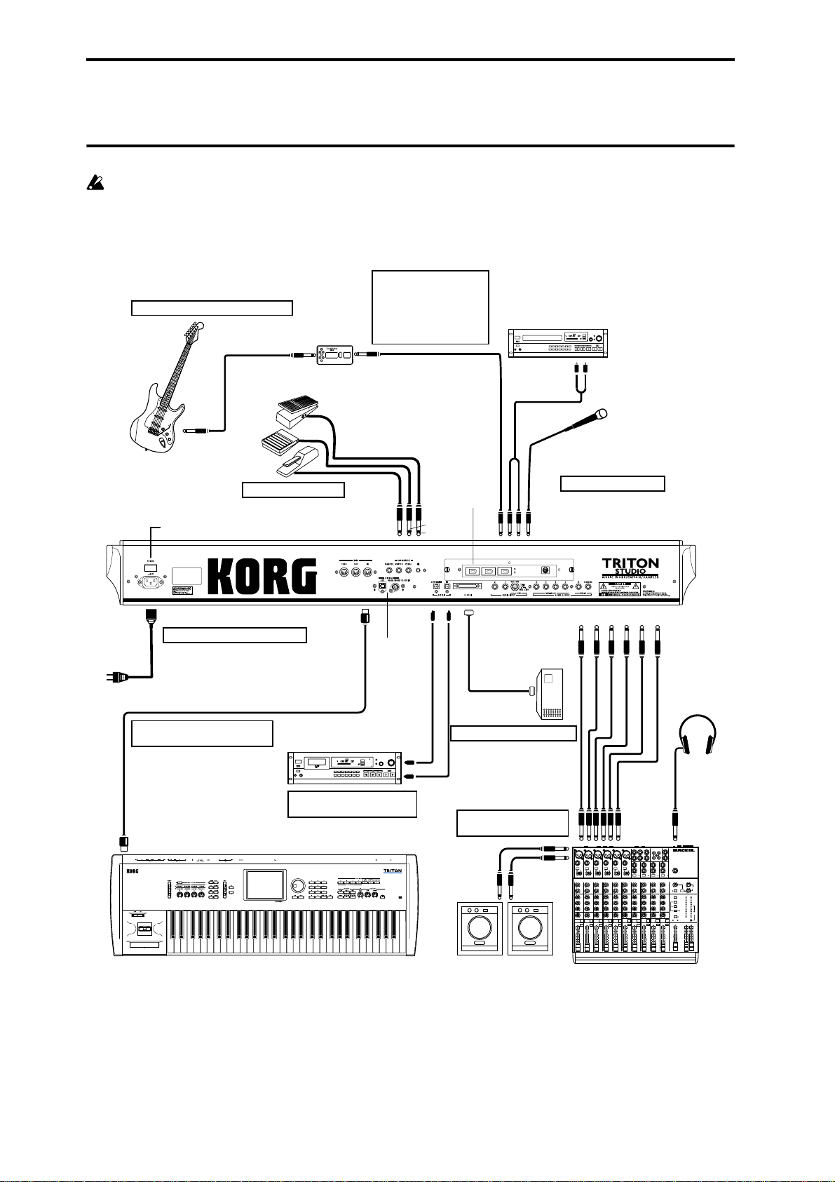
Connections
Connections must be made with the power turned
off. Please be aware that careless operation may damage your speaker system or cause malfunctions.
If a passive type guitar (a guitar
without an internal preamp) is
connected, it will not be possible
3. Analog audio input connections
to sample at an appropriate level
due to the impedance mismatch.
Such instruments must be
connected via a preamp or effect
unit.
CD player,
analog record player, etc.
Power Switch
AC power supply
1. Connecting the power cable
Power cable (Option)
to an AC outlet
MIDI cable
7. Connections to
MIDI equipment/computers
Effect processor etc.
5. Connecting pedals
MIDI OUT
DAT etc.
ASSIGNABLE
S/P DIF
SWITCH
PEDAL
DAMPER
OUT(MAIN) IN
EXB-DI
Option
DIGITAL IN
EXB-mLAN
Option
AUDIO INPUT 1, 2
SCSI
Hard disk,
Removable disk,
CD-R/RW etc.
AUDIO OUTPUT
6. SCSI device connections
AUDIO OUTPUT/
AUX OUT etc.
Mic
8. Installing options
(INDIVIDUAL) (MAIN)
4 3 2 1 R L/MONO
10
MIDI IN
4. Digital audio
input/output connections
DIGITAL OUT
Powered monitors,
etc.
2. Analog audio output
connections
Monitor
OUTPUT
INPUT
Mixer
MIC1
BAL
BAL
OR
OR
UNBAL
UNBAL
LINE IN 3
LINE IN 2
LINE IN 1
LOW CUT
LOW CUT
75Hz
75Hz
18dB/OCT
18dB/OCT
B
B
d
d
V
V
0
0
1
1
-
-
G
G
A
A
I
I
C
C
N
N
I
I
M
M
U
U
U
10
10
60
60
+10dB
+10dB
-40dB
-40dB
TRIM
TRIM
U
U
AUX
AUX
1
1
MON/
MON/
EFX
EFX
+15
+15
U
U
2
2
EFX
EFX
+15
+15
U
U
EQ
EQ
HI
HI
12kHz
12kHz
-15
-15
+15
-15
+15
U
U
MID
MID
2.5kHz
2.5kHz
-12
-12
-12
+12
+12
U
U
LOW
LOW
80Hz
80Hz
+15
+15
-15
-15
-15
PAN
PAN
L
L
L
R
R
1
2
MUTE
MUTE
MUTE
ALT 3–4
ALT 3–4
ALT 3–4
dB
dB
dB
10
10
10
SOLO
SOLO
5
5
5
U
U
U
5
5
5
10
10
10
20
20
20
30
30
30
40
40
40
50
50
50
60
60
60
1
2
LEFT(1/MONO)
RIGHT
BAL
BAL
BAL
BAL
MONO
OR
OR
OR
OR
UNBAL
UNBAL
UNBAL
UNBAL
L
LINE IN 4
LINE IN 6
LINE IN 5
BAL
LOW CUT
OR
LOW CUT
LOW CUT
LOW CUT
75Hz
75Hz
75Hz
75Hz
UNBAL
18dB/OCT
18dB/OCT
18dB/OCT
18dB/OCT
B
d
V
0
B
B
B
d
d
d
V
V
V
0
1
0
0
1
-
1
1
-
-
-
R
G
A
G
A
G
G
A
A
I
C
N
I
I
C
I
I
C
C
N
N
N
I
I
I
M
M
M
M
U
U
U
LEVEL
+4
10
60
10
10
10
60
60
60
-10
+10dB
-40dB
+10dB
-40dB
+10dB
+10dB
-40dB
-40dB
TRIM
LINE IN 7-8
TRIM
TRIM
TRIM
U
U
U
U
U
AUX
AUX
AUX
AUX
AUX
1
1
1
1
1
MON/
MON/
MON/
MON/
MON/
EFX
EFX
EFX
EFX
EFX
+15
+15
+15
+15
+15
U
U
U
U
U
2
2
2
2
2
EFX
EFX
EFX
EFX
EFX
+15
+15
+15
+15
+15
U
U
U
U
U
EQ
EQ
EQ
EQ
EQ
HI
HI
HI
HI
HI
12kHz
12kHz
12kHz
12kHz
12kHz
-15
+15
-15
-15
+15
+15
-15
+15
+15
U
U
U
U
U
MID
MID
MID
MID
MID
2.5kHz
2.5kHz
2.5kHz
2.5kHz
2.5kHz
-12
+12
-12
-12
-12
+12
+12
+12
+12
U
U
U
U
U
LOW
LOW
LOW
LOW
LOW
80Hz
80Hz
80Hz
80Hz
80Hz
+15
-15
+15
+15
+15
-15
-15
-15
+15
PAN
PAN
PAN
PAN
PAN
L
R
L
L
L
R
R
R
R
6
7–8
4
5
3
MUTE
MUTE
MUTE
MUTE
ALT 3–4
ALT 3–4
ALT 3–4
ALT 3–4
dB
dB
dB
dB
10
10
10
10
SOLO
SOLO
SOLO
SOLO
SOLO
5
5
5
5
U
U
U
U
5
5
5
5
10
10
10
10
20
20
20
20
30
30
30
30
40
40
40
40
50
50
50
50
60
60
60
60
INPUT
STEREO AUX RETURNS
MIC4
MIC6
MIC3
MIC5
MIC2
PHONES
MAIN OUTS
TAPE
TAPE
AUX SEND
OUTPUT
L
INPUT
1
MICRO SERIES 1402-VLZ
L
14-CHANNEL MIC/LINE MIXER
2
R
R
BAL/UNBAL
ALL BAL/UNBAL
MONO
MONO
MONO
L
L
L
BAL
BAL
BAL
OR
OR
OR
UNBAL
UNBAL
UNBAL
R
R
R
LEVEL
LEVEL
LEVEL
+4
+4
+4
PHONES
-10
-10
-10
LINE IN 13-14
LINE IN 9-10
LINE IN 11-12
U
U
U
U
U
AUX
AUX
AUX
1
1
1
MON/
MON/
MON/
EFX
EFX
EFX
1
+20
+10
+15
+15
+15
NORMALLED
U
+15
U
-15
+15
U
-12
+12
U
+15
-15
L
R
9–10
MUTE
ALT 3–4
dB
10
5
U
5
10
20
30
40
50
60
U
U
U
AUX 1 MASTER
2
PRE
2
2
2
POST
EFX
EFX
EFX
AUX
EFX TO
AUX 1
+20
MONITOR
+15
SELECT
+15
RETURNS
U
U
SOURCE
EQ
EQ
EQ
LEFT RIGHT
HI
HI
HI
MAIN
12kHz
MID
2.5kHz
LOW
80Hz
PAN
SOLO
CLIP+28
12kHz
12kHz
MIX
+10
-15
+15
-15
+15
+7
U
U
ALT
+4
3-4
MID
MID
2.5kHz
2.5kHz
+2
-12
-12
+12
+12
0
TAPE
U
U
-2
LOW
LOW
80Hz
80Hz
-4
+15
+15
-15
-15
-7
ASSIGN
PAN
PAN
-10
TO MAIN MIX
-20
NORMAL(AFL)
-30
LEVEL SET(PFL)
L
L
R
R
0dB=0dBu
SOLO
MODE
13–14
11–12
MUTE
MUTE
POWER
RUDE SOLO LIGHT
PHANTOM
ALT 3–4
ALT 3–4
CONTROL
/ PHONES
MAIN MIX
ROOM
dB
dB
dB
dB
10
10
10
10
SOLO
SOLO
5
5
5
5
U
U
U
U
5
5
5
5
10
10
10
10
20
20
20
20
30
30
30
30
40
40
40
40
50
50
50
50
60
60
60
60
Page 19
1. Connecting the power cable
Connect the included power cable to the AC power
supply inlet of the TRITON STUDIO, and then connect the other end of the cable to an AC outlet.
2. Analog audio output connections
Connect a set of amplified monitor speakers or your audio
system to the TRITON STUDIO.
If you play back the TRITON STUDIO through your
stereo audio system, be aware that high volumes may
damage your speakers. Be careful not to raise the volume excessively.
Connecting the AUDIO OUTPUT (MAIN) L/MONO,
R, (INDIVIDUAL) 1, 2, 3, and 4 jacks to the INPUT
jacks of your mixer or powered monitor system.
L/MONO and R are the main outputs. If you are outputting in stereo, make your connections using the
(MAIN) L/MONO jack and the R jack. If you are outputting in mono, make your connection to the (MAIN)
L/MONO jack.
The (INDIVIDUAL) 1, 2, 3, and 4 jacks are used to output specific sounds independently. For example, you
can use these to apply an external effect to the snare
sound of a drum kit.
When you are sampling, and want to hear the sounds
played by the TRITON STUDIO’s sequencer while you
sample only the external audio source, send the source
to (INDIVIDUAL) 1 and 2. If you want to monitor this
sound, you can connect (INDIVIDUAL) 1 and 2 jacks
to your mixer, and monitor the sound via your mixer.
(☞For details on routing methods, refer to p.140–)
Headphones
If you are using headphones, connect them to the
headphone jack of the TRITON STUDIO.
The TRITON STUDIO’s headphone jack will output
the same signal as (MAIN) L/MONO and R.
If you are using (INDIVIDUAL) 1, 2, 3, and 4, connect
these jacks to your mixer, and use the headphone jack
of your mixer to monitor the sound.
3. Analog audio input connections
You can input external analog audio sources, and sample
them or process them with the internal effects and output
them from the OUTPUT jacks.
Connect mics or the OUTPUT jacks of your external
audio equipment to the AUDIO INPUT 1 and 2 jacks.
4. Digital audio input/output connections
Digital audio output
The same audio signal present at the TRITON STUDIO’s
AUDIO OUTPUT (MAIN) L/MONO and R jacks can be
output in digital format to a DAT, MD, or digital multitrack recorder that can accept a digital audio input with a
sample frequency of 48 kHz or 96 kHz.
Use an optical cable to connect the S/P DIF OUT
(MAIN) jack to the optical digital input jack of your
DAT, MD, or digital multitrack recorder.
The [VOLUME] slider does not affect the volume of
this output jack.
Digital audio input
TRITON STUDIO can accept a digital audio input from a
DAT or other digital device that can output digital audio
at a sampling frequency of 48 kHz or 96 kHz. This signal
can be input to the L and R channels, then sampled or processed by the internal effects and output from the OUTPUT jacks.
Use an optical cable to connect the optical digital output jacks of your DAT etc. to the S/P DIF IN jack.
If the EXB-mLAN option is installed, digital audio
can be input/output via the mLAN connector. If the
EXB-DI option is installed, digital audio can be output via the DIGITAL OUT jack. (☞PG p.286)
5. Connecting pedals
Foot pedal connections
A foot pedal can be used to control various synthesis and
effect parameters.
Connect an optional expression pedal such as the Korg
XVP-10 or EXP-2 to the rear panel ASSIGNABLE PEDAL
jack.
The function controlled by the foot pedal is specified in
Global: P2 “Foot Pedal Assign” (☞p.125, PG p.146, 252)
Foot switch connections
A foot switch controls sostenuto, soft pedal on/off, arpeggiator on/off, to select programs or combinations, and to
start/stop the sequencer etc.
Connect an optional foot switch such as the Korg PS-1 to
the rear panel ASSIGNABLE SWITCH jack.
The function assigned to the foot switch and the polarity
of the foot switch can be set in Global: P2 “Foot Switch
Assign,” and “Foot Switch Polarity” (☞p.125, PG p.146,
251)
Damper pedal connections
This pedal applies a piano style damper effect as you play .
Connect an optional footswitch to the DAMPER jack of
the TRITON STUDIO. If a Korg DS-1H is connected, halfdamper effects can be produced.
The polarity of the pedal is set in Global P2: Controller
“Damper Polarity” and the sensitivity is set in Global P0
“Half Damper Calibration.” (☞PG p.137, 146)
Introduction
FeaturesFront &
rear panel
LCD screenConnectionsBasics
11
Page 20
6. SCSI device connections
7. Connections to MIDI equip-
By connecting an external SCSI device such as a hard disk
drive or CD-R/RW drive to the SCSI connector, you can
manage large amounts of data on devices other than the
internal hard drive. If a hard disk drive is connected, it
can also be specified as the destination when sampling.
☞ For details on connecting SCSI devices, refer to PG
p.298.
About SCSI devices that can be used with the TRITON STUDIO
• To store data, the TRITON STUDIO can use either
DOS-formatted SCSI disks or UDF-formatted CD-R/
RW discs.
• In some cases it will not be possible to use a DOSformat or UDF-format disk that was formatted on a
personal computer. As far as possible, please use the
TRITON STUDIO to format the disc.
• The TRITON STUDIO can use MO disks of 128
Mbytes, 230 Mbytes, 540 Mbytes, 640 Mbytes, and 1.3
Gbyte capacities.
ment/computers
Connections to MIDI equipment
The keyboard, controllers, and sequencer etc. of TRITON
STUDIO can be used to control an external MIDI tone
generator. Conversely, another MIDI keyboard or
sequencer can control the tone generator of TRITON STUDIO to produce sound.
Use MIDI cables to connect the MIDI connectors of
TRITON STUDIO with the MIDI connectors of your
external device.
☞ PG p.258 “MIDI applications – Connecting MIDI
deveices/computers”
Connections to a computer
Your performance on the TRITON STUDIO, as well as
controller and sequencer data, can be sent to a computer
(connected via MIDI interface), and the tone generator of
TRITON STUDIO can be played from the computer.
Use a MIDI interface to connect the MIDI connectors
of TRITON STUDIO to the MIDI connectors of your
computer.
☞ PG p.258 “MIDI applications – Connecting MIDI
deveices/computers”
Some USB-MIDI interfaces may not be able to transmit or receive the TRITON STUDIO’s MIDI exclusive
messages.
If the EXB-mLAN option is installed, MIDI messages
can be exchanged via the mLAN connector between
the TRITON STUDIO and an external mLAN-compatible MIDI device or a FireWire-capable Macintosh
computer. For details on connections, refer to the
“EXB-mLAN owner’s manual” included with the
EXB-mLAN option.
At present, a TRITON STUDIO MIDI data dump sent
via the EXB-mLAN option to a computer cannot be
recorded or played back by an OMS-compatible
application. (The same applies to the TRITON-Rack.)
12
8. Installing options
The functionality of the TRITON STUDIO can be
extended by installing option boards and/or sample
memory. The following six types of options can be
installed. For details on installation, refer to PG p.286.
• EXB-MOSS (DSP synthesizer board)
• EXB-DI (Digital interface board)
• EXB-mLAN (mLAN interface board)
• CDRW-1 (CD-R/RW drive)
• EXB-PCM series (PCM expansion boards)
• DRAM SIMM (Memory boards for sample data)
Page 21

Basic concepts
Introduction
Overview of the modes
The TRITON STUDIO has a large number of functions
that let you play and edit programs and combinations,
record and play sequence data, record and play back samples, and manage data on disk. The largest unit used to
organize these functions is called a mode.
The TRITON STUDIO has seven modes.
Program mode
• Select and play programs
You can choose programs from rewritable banks INTA–INT-F and EXB-A–EXB-G which contain a total of
1,664 programs, and non-rewritable bank INT-G (256
programs compatible with the GM2 standard, and nine
drum programs).
(The 128 programs of bank INT-F can be selected only
if the EXB-MOSS option has been installed.)
• Sample or resample.
For example you can sample an external audio source
while listening to the performance of the arpeggiator,
or resample a performance you play using a program.
• Edit a program
Make settings for the oscillator, filter, amp, EG, LFO,
effects, and arpeggiator.
The following multisamples are available for the oscillator.
• 429 internal multisamples (ROM, Piano)
• Expanded multisamples (when one or more EXBPCM series board are installed)
• Multisamples (RAM) that you sampled on the
TRITON STUDIO or loaded in from media
• Create drum programs using a drum kit (created in
Global mode)
Combination mode
• Select and play combinations
A combination is a set of two or more programs (a
maximum of eight), and allows you to produce complex sounds that could not be created by an individual
program.
You can choose combinations from rewritable banks
INT-A–INT-E and EXB-A–EXB-G which contain a total
of 1,536 combinations.
• Sample or resample.
For example you can sample an external audio source
while listening to the performance of the arpeggiators,
or resample a performance you play using a combination.
• Edit a combination
Make settings for volume, pan, layer/split etc. for each
timbre (program), and make settings for effects and the
two arpeggiators.
FeaturesFront &
rear panel
LCD screenConnectionsBasics
Analog Audio
CDRW-1
CD-ROM Write Audio CD
Ripping
SAMPLING MODE
Resampling
Resampling
AUDIO INPUT
1
S/P DIF IN
L
mLAN IN
1
Insert Effect
IFX 1
IFX 2
IFX 3
Sample
Sample
Sample
AUDIO INPUT
S/P DIF IN
mLAN IN
Sample
IFX 4
IFX 5
2
R
2
GLOBAL MODE
DISK MODE
Multisample
Multisample
Sample
Sample
Sample
DRUM KIT
Key
Drumsample / Sample - H
Assign
Drumsample / Sample - L
ARPEGGIATOR PATTERN
Preset Arpeggio
Pattern: P0 - 4
User Arpeggio
Pattern: U00 - 231
Hard Disk
PROGRAM
OSC 1
Multisample - H
Drum Kit
Multisample - L
FILTER1 AMP1
PITCH1
OSC 2
Multisample - H
Multisample - L
FILTER2
PITCH2
COMBINATION
TIMBRE 1
PROGRAM
TIMBRE 2
PROGRAM
TIMBRE 3
PROGRAM
TIMBRE 4
PROGRAM
TIMBRE 5
PROGRAM
TIMBRE 6
PROGRAM
TIMBRE 7
PROGRAM
TIMBRE 8
PROGRAM
SEQUENCER / SONG PLAY
TRACK 1
TRACK 2
TRACK 3
TRACK 4
TRACK 5
TRACK 6
TRACK 7
TRACK 8
PROGRAM
PROGRAM
PROGRAM
PROGRAM
PROGRAM
PROGRAM
PROGRAM
PROGRAM
TRACK 9
TRACK 10
TRACK 11
TRACK 12
TRACK 13
TRACK 14
TRACK 15
TRACK 16
AMP2
PROGRAM
PROGRAM
PROGRAM
PROGRAM
PROGRAM
PROGRAM
PROGRAM
PROGRAM
Insert / Master Effect
IFX 1
IFX 2
IFX 3
IFX 4
IFX 5
Arpeggiator
Insert /Master Effect
IFX 1
IFX 2
IFX 3
IFX 4
IFX 5
Arpeggiator - A
Arpeggiator - B
Insert /Master Effect
IFX 1
IFX 2
IFX 3
IFX 4
IFX 5
Arpeggiator - A
Arpeggiator - B
MFX 1
MFX 2
MEQ
MFX 1
MFX 2
MEQ
MFX 1
MFX 2
MEQ
Only SEQ
13
Page 22

Sequencer mode
• Use the 16-track sequencer to record and playback
songs.
• Sample or resample.
You can sample an external input source while listening to the song play back. You can also cause a corresponding note event to automatically be created at this
time, allowing you to sample an external source just as
if you were recording an audio track. (The In-Track
Sampling function.)
The playback of a song can also be resampled. After
resampling one or more songs to the hard disk, you can
use Disk mode to create an audio CD from those songs.
• Make effect settings for the song.
• You can record a performance that uses the
arpeggiator(s) into a song or pattern.
• You can use a cue list to create an arrangement using
individual songs for each verse, chorus, bridge, etc.,
and specify the number of repeats for each song.
• You can use a maximum of 20 cue lists, 200 songs, and
100 preset patterns. One song can use as many as 100
patterns.
• The TRITON STUDIO can be used as a 16-track
multitimbral tone generator.
• Record patterns and assign them to individual keys,
using the RPPR (Realtime Pattern Play/Recording)
function.
• Perform using the RPPR (Realtime Pattern Play/
Recording) function, and adjust the various settings.
• Create drum kits using the 417 internal drumsamples
(ROM). You can also use drumsamples from an
optional EXB-PCM series board (if installed), or
samples (RAM) that you created in Sampling mode.
• Rename program and combination categories.
• Set the function of the assignable pedals and
assignable switches.
• Transmit data dumps of MIDI exclusive data.
Disk mode
• Data of each mode can be saved and loaded using the
floppy disk drive, the internal hard drive, the CDRW-1
option or an external SCSI device.
• Format the above types of media. You can also
manage data by copying it, etc.
• Korg, AKAI, AIFF, and WAVE format sample data can
be loaded. Sample data can also be saved in Korg
format, or exported in AIFF or WAVE formats.
• Songs that you created in Sequencer mode can be
saved in SMF format. SMF files can be loaded as
Sequencer mode songs.
• You can use the Data Filer function (to save/load
MIDI exclusive data).
• WAVE files can be edited (arranged in the desired
song order) to create an audio CD. Audio CDs can also
be played.
Song Play mode
• SMF (Standard MIDI File) data can be played back
from a floppy disk, the internal hard drive, or an
external SCSI device, and you can perform along with
the playback.
• Make effect settings for use in Song Play mode.
• The arpeggiator can be used while you play along
with the SMF playback.
• SMF songs can be played back in succession.
You can use the jukebox function to playback songs in
any specified order.
Sampling mode
• Sample external audio sources (i.e., record samples).
Insert effects can be applied to the external input sound
while you sample.
• Edit the waveform data you sampled or waveform
data that you loaded in from media, and set loop
points etc.
• Edit multisamples consisting of two or more samples.
• A multisample can be converted into a program, so
that a multisample created in Sampling mode can be
used in the Program, Combination, Sequencer, or Song
Play modes.
• Sample digital data (“rip”) directly from an audio CD.
You can also play back audio CDs.
Global mode
• Make settings that affect the entire TRITON STUDIO,
such as master tune and global MIDI channel.
• Create user drum kits (144 kits), user arpeggio
patterns (507 patterns), and user scales (16 one-octave
scales and 1 all-note scale).
14
Page 23
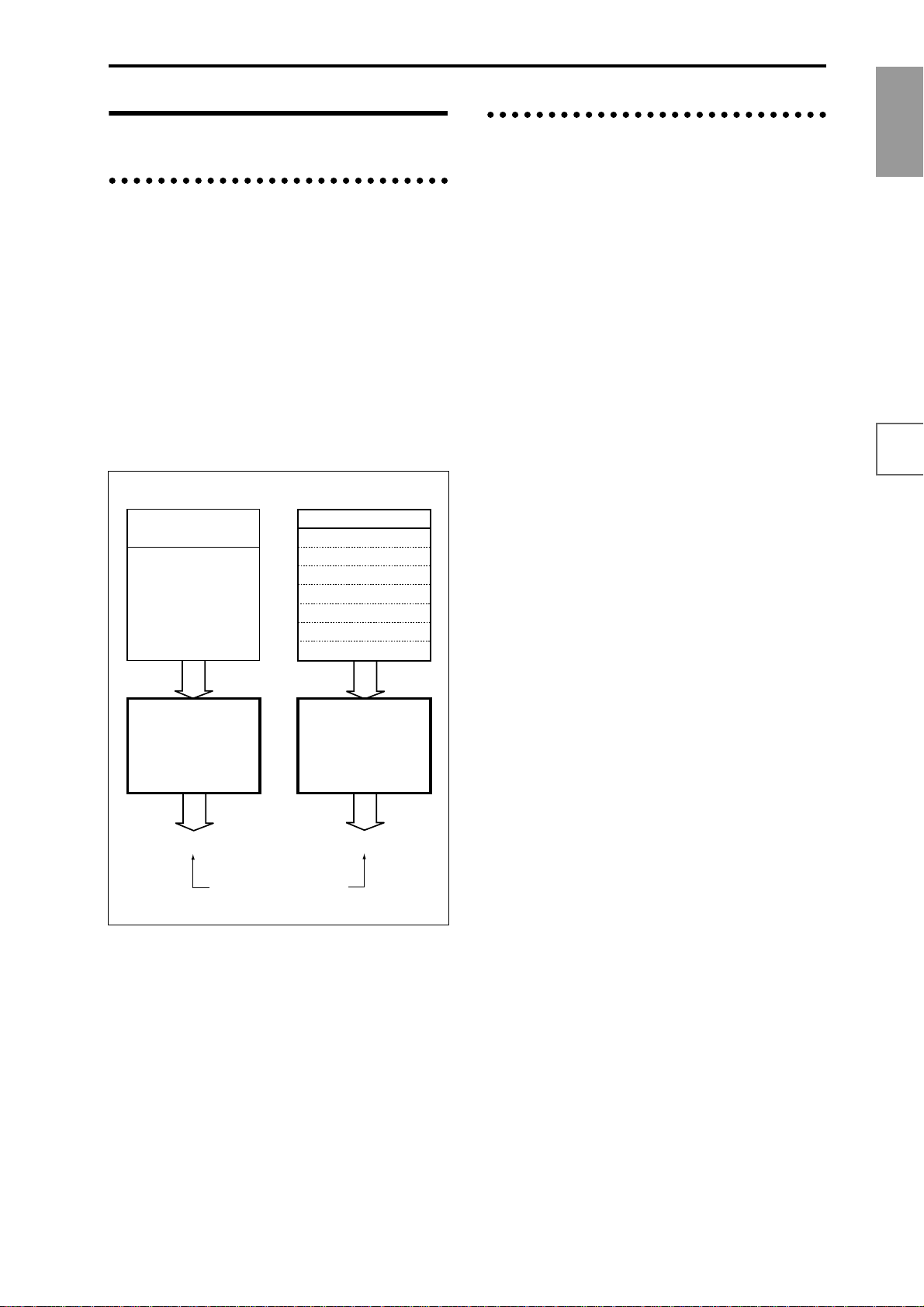
About polyphony
Tone generators and oscillators
The oscillators of the TRITON STUDIO are sounded by
two Tone Generators.
Each tone generator is connected to the various PCM
memories as shown in the diagram below.
Tone Generator 1
• ROM: Internal PCM ROM (32 Mbytes)
• RAM: User sample memory (16 Mbytes, expandable
to a maximum of 96 Mbytes)
Tone Generator 2
• Piano: Internal Piano PCM ROM (16 Mbytes)
• EXB-PCM: Expansion PCM ROM (16 Mbytes each;
maximum of 7 boards totaling 112 Mbytes)
PCM memory
ROM (Internal PCM ROM) 32 Mbytes
RAM
(User sample memory)
96 Mbytes*
* = Expandable to a maximum.
Tone Generator 1
Maximum 60 oscillators
Factory settings is 16 Mbytes
PCM memory
Piano (Internal Piano PCM ROM)
EXB-PCM (Expansion PCM ROM Slot1)
EXB-PCM (Expansion PCM ROM Slot2)
EXB-PCM (Expansion PCM ROM Slot3)
EXB-PCM (Expansion PCM ROM Slot4)
EXB-PCM (Expansion PCM ROM Slot5)
EXB-PCM (Expansion PCM ROM Slot6)
EXB-PCM (Expansion PCM ROM Slot7)
Tone Generator 2
Maximum 60 oscillators
16 Mbytes
16 Mbytes
16 Mbytes
16 Mbytes
16 Mbytes
16 Mbytes
16 Mbytes
16 Mbytes
Number of voices in each mode
The maximum number of voices that can be played simultaneously will depend on the oscillator mode of the program.
• For a Single/Drum-mode program, 1 oscillator = 1
voice
• For a Double-mode program, 2 oscillators = 1 voice
Program mode
Single/Drum-mode
Normally, 60 voices can be used.
However a maximum of 120 voices will be available if, for
example, ROM or RAM is used for the High MS, and
Piano or EXB-PCM is used for the Low MS, and you use
velocity switching to play the two tone generators.
Double mode
Normally, 30 voices can be used.
However if OSC1 is sounded by one tone generator and
OSC2 is sounded by the other tone generator (e.g.,
OSC1=ROM, OSC2=Piano), a maximum of 60 voices can
be used. If OSC1 and OSC2 use one tone generator (e.g.,
OSC1=ROM, OSC2=ROM), then a maximum of 30 voices
can be used.
This can also be increased by velocity switch and velocity
zone settings.
Combination, Sequencer, and Song Play modes
Depending on the oscillator mode of the programs you
are using, the maximum number will vary between 60
voices and 120 voices.
(Example)
For single-mode programs that use ROM or RAM, a total
maximum of 60 voices
For single-mode programs that use Piano or EXB-PCM, a
total maximum of 60 voices
Total 120 voices
For double-mode programs that use ROM or RAM, a total
maximum of 30 voices
For double-mode programs that use Piano or EXB-PCM, a
total maximum of 30 voices
Total 60 voices
Introduction
FeaturesFront &
rear panel
LCD screenConnectionsBasics
Total maximum 120 oscillators
Each tone generator is able to simultaneously sound up to
60 oscillators (i.e., to play the PCM data connected to that
tone generator). Together, the two tone generators are able
to sound up to 120 oscillators.
However, it is not possible, for example, to simultaneously play 61 or more oscillators from only the internal
PCM ROM.
Sampling mode
Tone generator 1 is always used in Sampling mode.
Mono samples/multisamples
60 voices.
Stereo samples/multisamples
30 voices.
15
Page 24
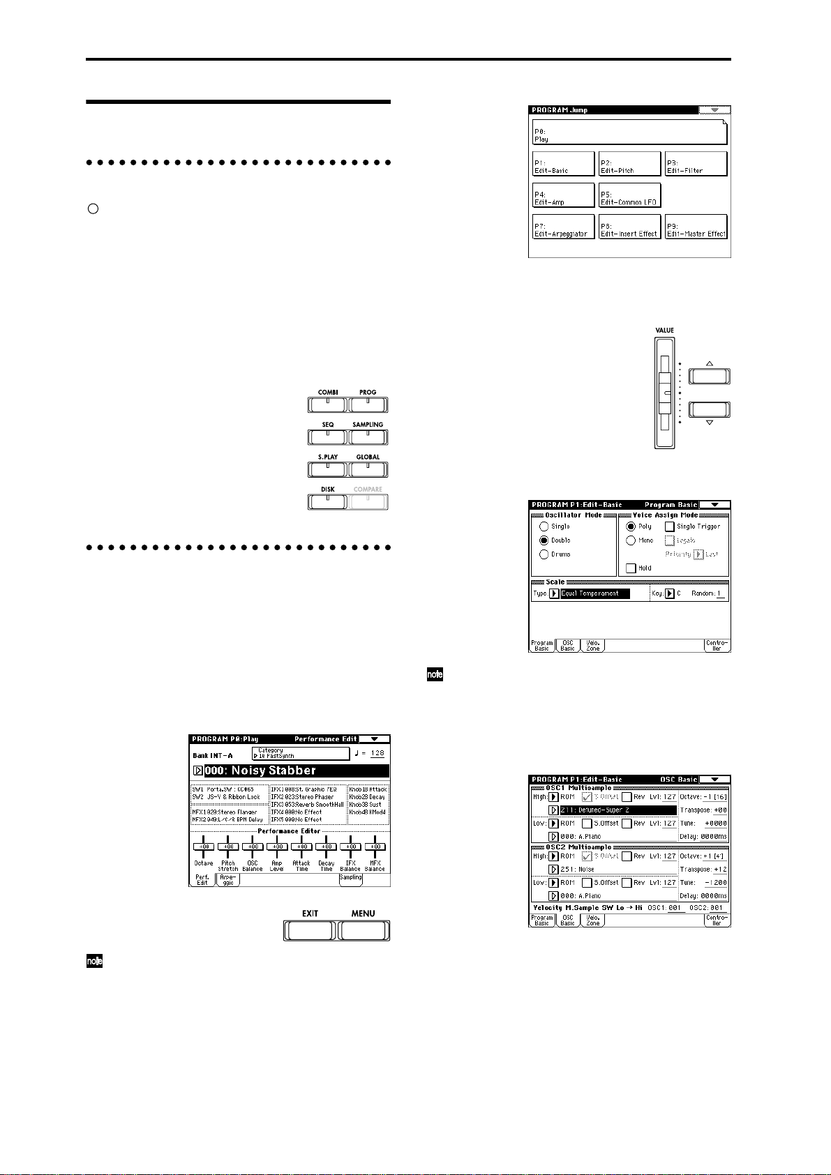
Basic operation
1. Selecting modes
In order to use a particular function on the TRITON
STUDIO, you must first select the appropriate mode.
Press one of the front panel mode keys ([COMBI] key
– [DISK] key) to enter the corresponding mode.
[COMBI] key: Combination mode
[PROG] key: Program mode
[SEQ] key: Sequencer mode
[SAMPLING] key: Sampling mode
[S.PLAY] key: Song Play mode
[GLOBAL] key: Global mode
[DISK] key: Disk mode
3 In the LCD screen, press the desired page.
You will jump to the selected page, and it will appear
in the display. As an example here, press P1: Edit-Basic.
• As a reminder, the page that was
selected before you pressed the
[MENU] key will have its top right
corner bent over.
• You can also jump to the
corresponding page by pressing a
numeric key [0]–[9]. (P0–P9
correspond to numeric keys [0]–[9].)
• By holding down the [MENU] key
and pressing a numeric key [0]–[9],
you can jump directly to the corresponding page
without displaying the page jump menu.
2. Selecting pages
Each mode has a large number of parameters, which are
grouped into pages.
These are further subdivided by tabs into up to eight tab
pages.
1 Make sure that the desired mode is selected.
To select a mode, press the appropriate mode key
([COMBI] key – [DISK] key).
Here we will use Program mode as an example for our
explanation. Press the [PROG] key.
2 Press the [MENU] key.
The page jump menu will
appear.
In Disk mode there is only one page, so the page
jump menu will not appear.
When you press the [EXIT] key, you will return to P0
from any page.
4 Press one of the tabs located at the bottom of the
page.
As an example here, press the OSC Basic tab which is
the second from the left.
• Some pages have no tabs.
5 To move to a page with a different ‘P’ number, press
the [MENU] key and continue from step 2 of this
procedure.
16
Page 25
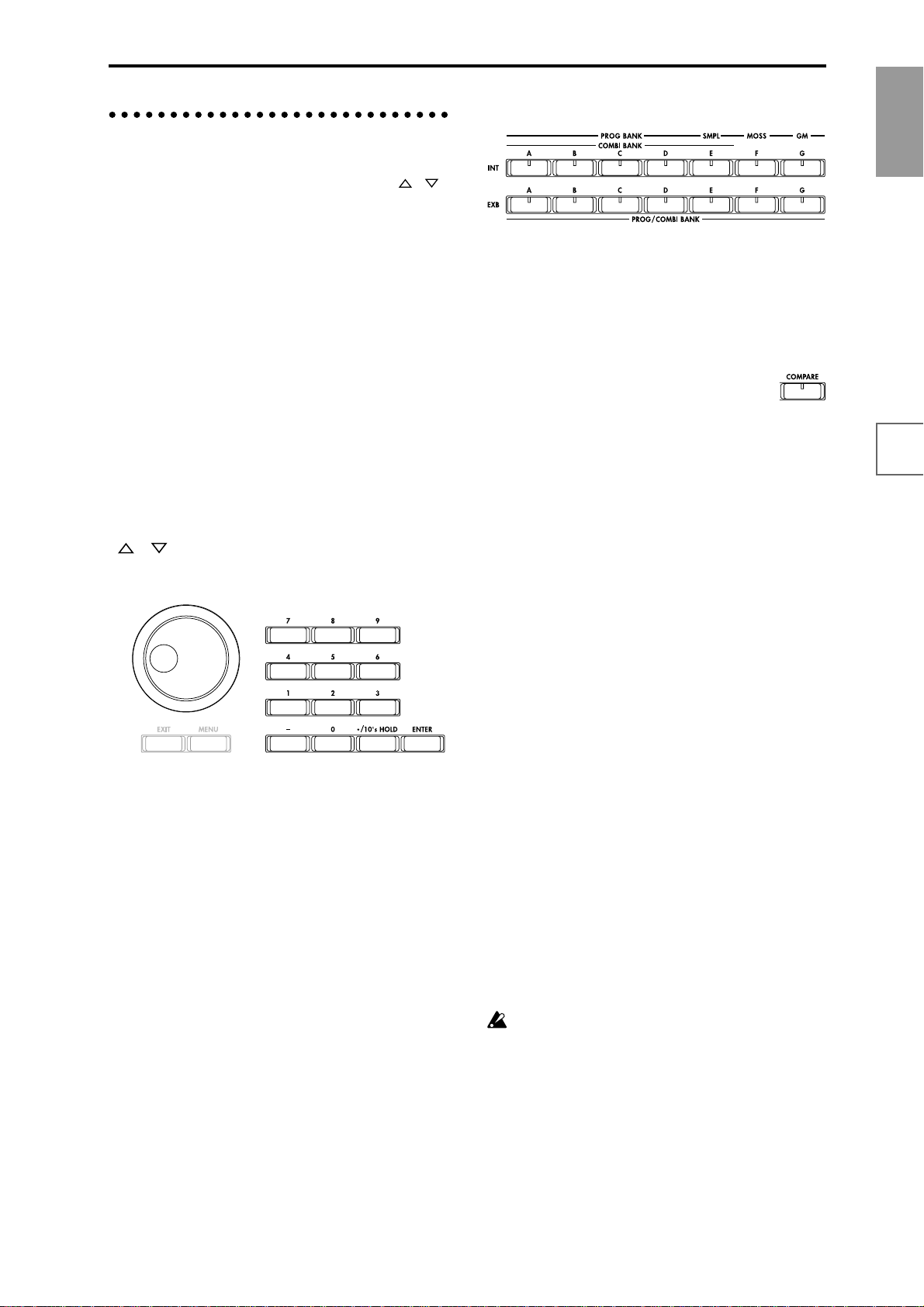
3. Setting a parameter
The parameter value in the edit cell can be set by using the
front panel VALUE controllers ([VALUE] slider, [ ][ ]
keys, [VALUE] dial, numeric keys [0]–[9], [–] key,
[ENTER] key, and [./10’s HOLD] key). As necessary, you
can also use the [BANK] keys and the [COMPARE] key.
For some parameters, the value can be set by pressing a
popup button to display the popup menu and then selecting a parameter value, or by holding down the [ENTER]
key and playing a note on the keyboard to input a note
number or velocity value.
VALUE controllers
[VALUE] slider
Use this when you wish to make major changes in the
value.
In Program mode and Combination mode, this slider can
also be used as a control source for alternate modulation
or dynamic modulation. (This is active in Program or
Combination P0: Play when the “Program Select” or
“Combination Select” (the large characters in the upper
part of the LCD) is selected).
[ ][ ] keys
Use these when you wish to make small changes in the
value.
[VALUE] dial
Use this when you wish to make large changes in a value.
Numeric keys [0]–[9], [ENTER] key, [–] key,
[./10’s HOLD] key
Use these when you know the parameter value that you
wish to input.
After using the numeric keys [0]–[9] to input a number,
press the [ENTER] key to finalize the parameter value.
Use the [–] key to enter negative numbers.
Use the [./10’s HOLD] key to enter a decimal point.
In Program and Combination mode P0: Play page other
than the Sampling page, the [./10’s HOLD] key performs
the 10’s Hold function. (☞p.23, 24)
BANK [INT-A]–[INT-G], [EXB-A]–[EXB-G] keys
The BANK [INT-A]–[INT-G], [EXB-A]–[EXB-G] keys are
used in Program mode to select the program bank and in
Combination mode to select the combination bank. In
combination, Sequencer and Song Play modes, these keys
are used to select the bank of the program used by each
timbre/track.
[COMPARE] key
Use this key when you wish to compare the edits you
have made to a program or combination’s sound with the
un-edited original (i.e., the sound that is written into
memory).
When editing a program or combination, press this key.
The LED will light, and the last-written settings for that
program number or combination number will be recalled.
When you press the [COMP ARE] key once again, the LED
will go dark and you will return to the settings that you
were editing.
If you edit the settings that are recalled by pressing the
[COMPARE] key (i.e., the settings that are written into
memory), the LED will go dark, and it will not be possible
to return to the previous edits by pressing the [COMPARE] key again.
In Sequencer mode, you can use the [COMPARE] key to
make “before and after” comparisons immediately after
using realtime recording or step recording to record a
song, or after performing a track edit operation.
For example, this can be used effectively when realtimerecording a track for a song.
1 Realtime-record a track. (Take 1)
2 Once again, realtime-record on the same track. (Take 2)
3 Press the [COMPARE] key. The LED will light, and
take 1 will be recalled.
4 Press the [COMP ARE] key once again. The LED will go
dark, and take 2 will be recalled.
5 If at step 3 you once again realtime-record on the
same track (take 3), the object of the Compare function
will now be take 1. If at step 4 you once again realtime-record on the same track (take 3), the object of the
Compare function will be take 2.
In this way, the Compare function lets you recall the previous recording or the previous state of event editing.
The Compare function is not available Sampling,
Song Play, Global, or Disk modes.
Introduction
FeaturesFront &
rear panel
LCD screenConnectionsBasics
17
Page 26

Popup buttons and popup menus
You can press a popup button to access a popup menu,
and then set parameter values (☞p.8).
Keyboard input
When inputting a note number or a specific velocity as the
value of a parameter, you can use the keyboard to input
the setting. Hold down the [ENTER] key and play the
note that you wish to enter as a value. The note number or
velocity value will be input.
When the Global P5: Drum Kit page is displayed, you can
hold down the [ENTER] key and play a note to recall the
settings that have been assigned to that note.
In Sampling mode, you can hold down the [ENTER] key
and play a note to recall the index that is assigned to that
note.
18
Page 27
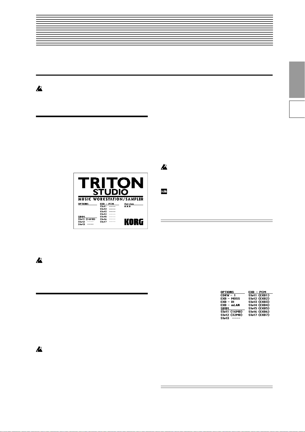
Quick Start
Turning the power on/off
Before you turn on the power, make sure that the
desired connections have been made as described in
“Connections” (☞p.10).
1. Turning the power on
1 Press the rear panel [POWER] switch to turn on the
power.
The LCD screen will display the name of your model,
and the software version.
(The following graphic shows the factory-set LCD
screen. The version number is subject to change without notice.)
2 Turn on your powered monitors or stereo amp.
3 Raise the TRITON STUDIO’s [VOLUME] slider to an
appropriate level, and adjust the volume of your
powered monitors or stereo amp.
If an external SCSI device is connected, turn on the
power of the external SCSI device and then wait ten
seconds or longer before you turn on the power of the
TRITON STUDIO.
2. Turning the power off
1 Set the front panel [VOLUME] slider and the volume
of your powered monitor or stereo amp to zero.
2 Turn off the power of your powered monitor or stereo
amp.
3 Press the TRITON STUDIO’s [POWER] switch to
turn off the power.
Never turn off the power while data is being written
into internal memory.
If the power is turned off while processing is being
performed, memory write operations will not be
completed correctly. If this occurs, TRITON STUDIO
will automatically initialize its internal memory so
that it will operate correctly. This is not a malfunction.
While data is being written, the LCD screen will indicate “Now writing into internal memory.” Data is written into internal memory by the following operations.
• Writing (updating) a Program, Combination, Global
Setting, Drum Kits, or Arpeggio Patterns
• Loading Program, Combination, Global Setting, Drum
Kit, or Arpeggio Patterns data in Disk mode
• Receiving a MIDI data dump for Program,
Combination, Global Setting, Drum Kit, or Arpeggio
Patterns
• When using Sampling mode page menu commands
(“Move Sample,” “Move MS,” “Convert To Program,”
“Time Slice,” etc.) to simultaneously modify programs
or drum kits.
• When sampling to RAM in Program, Combination, or
Sequencer mode, if you simultaneously convert the
sample to a program.
Never turn off the power while the hard disk or other
media is being accessed. If you turn off the power
while media is being accessed, the media may
become unusable.
You can set the “Power On Mode” (Global P0: System
Preference page) so that the mode and page that had
been selected when you turned the power off will
appear when the power is turned on. (
☞p.125
)
Information displayed in the LCD screen when various options or SIMM modules are installed
The TRITON STUDIO allows you to install separately
sold options or sample memory (RAM) boards.
When the power is turned on, the type of installed options
will be displayed. After installing an option, be sure to
check this display to verify that the option was installed
correctly. If the option is not displayed here even though it
was installed, it was not installed correctly. Turn off the
power and re-install the option. (☞For details on installing an option, refer to PG p.286)
OPTIONS
CDRW-1: The CDRW-1
option is installed.
EXB-MOSS: The EXB-MOSS
option is installed.
EXB-DI: The EXB-DI option is
installed.
EXB-mLAN: The EXB-mLAN option is installed.
SIMM
Slot 1...3 (** MB): Sample memory (RAM)’s are installed
in SIMM slots 1–3. The capacity of each SIMM is shown in
parentheses. When shipped from the factory, a 16 MB
SIMM is installed in SIMM slot 1.
EXB-PCM
Slot 1...7 (****): PCM expansion boards are installed in
EXB-PCM series slots 1–7. The model number of each
board is shown in parentheses.
Quick Start
Power on/offDemo songPlaying
programs
Playing
combinations
Using
controllers
ArpeggiatorRPPRProgram
editing
editing
Combination
SamplingSong
19
Page 28
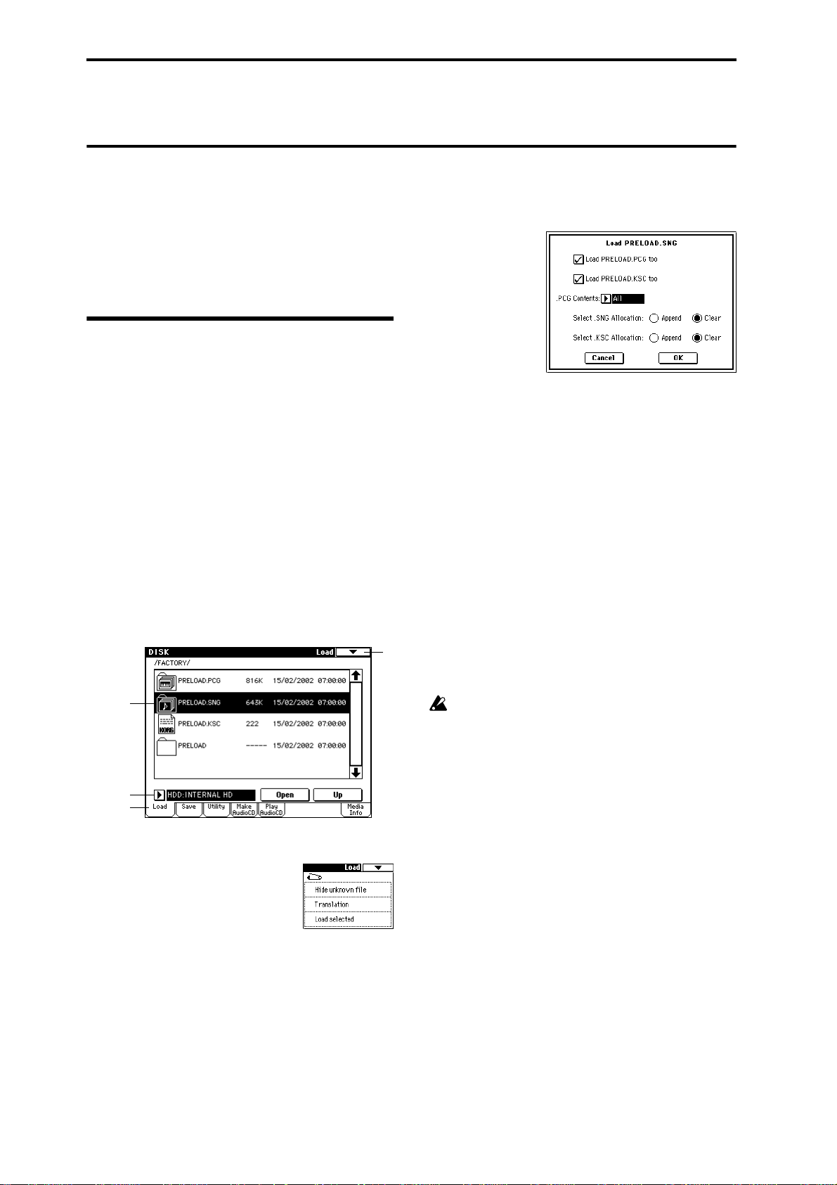
Listening to a demo song
Here’s how to listen to demo songs on the TRITON STUDIO.
This section explains how the demo song data can be
loaded from the internal hard drive using the Disk mode,
and played back in Sequencer mode.
We will explain how to play back songs individually, or
consecutively using the Cue List function.
1. Loading the demo song data in Disk mode
1 Press the [DISK] key (the LED will light).
You will enter Disk mode.
2 Press the Load tab.
The Disk, Load page will appear.
3 Press the drive select popup button, and select HDD:
(internal hard drive) which is the second from the
bottom in the popup menu.
File information for the internal hard disk will be displayed.
4 Press the FACTORY directory, and then press the
Open button.
You will move to the next lower directory.
5 Press “PRELOAD.SNG.”
The display will be highlighted. This is the demo song
data.
5
3
Drive
Select
2
8 Check the data that you want to load along with the
song.
In this case, make the settings shown below.
• Check “Load PRELOAD.PCG too”
If this is checked, the .PCG file will be loaded along
with the .SNG file when you execute the Load operation.
• Check “Load PRELOAD.KSC too”
If this is checked, the .KSC file will be loaded along
with the .SNG file when you execute the Load operation.
The “Select .SNG Allocation” radio buttons specify
how the song data will be loaded into internal memory.
For this example, select Clear.
The “Select .KSC Allocation” radio buttons specify
how the sample data will be loaded into sample memory (RAM). For this example, select Clear.
If you load with “Select .KSC Allocation” set to Clear,
the sample data will be loaded from the beginning of
the sample memory (RAM) area.
6
If you load with “Select .KSC Allocation” set to
Append, the sample data will be loaded into the
unused portion of the sample memory (RAM).
If sample memory (RAM) already contains sample
data that you do not wish to lose, either select
Append, or save the sample data to a internal hard
disk (☞p.59).
9 Press the OK button.
The data will be loaded in the order of PRELOAD.PCG, PRELOAD.SNG, and PRELOAD.KSC.
6 Press the page menu button.
The page menu commands will be displayed.
7 Press “Load selected.”
A dialog box will appear.
20
Page 29
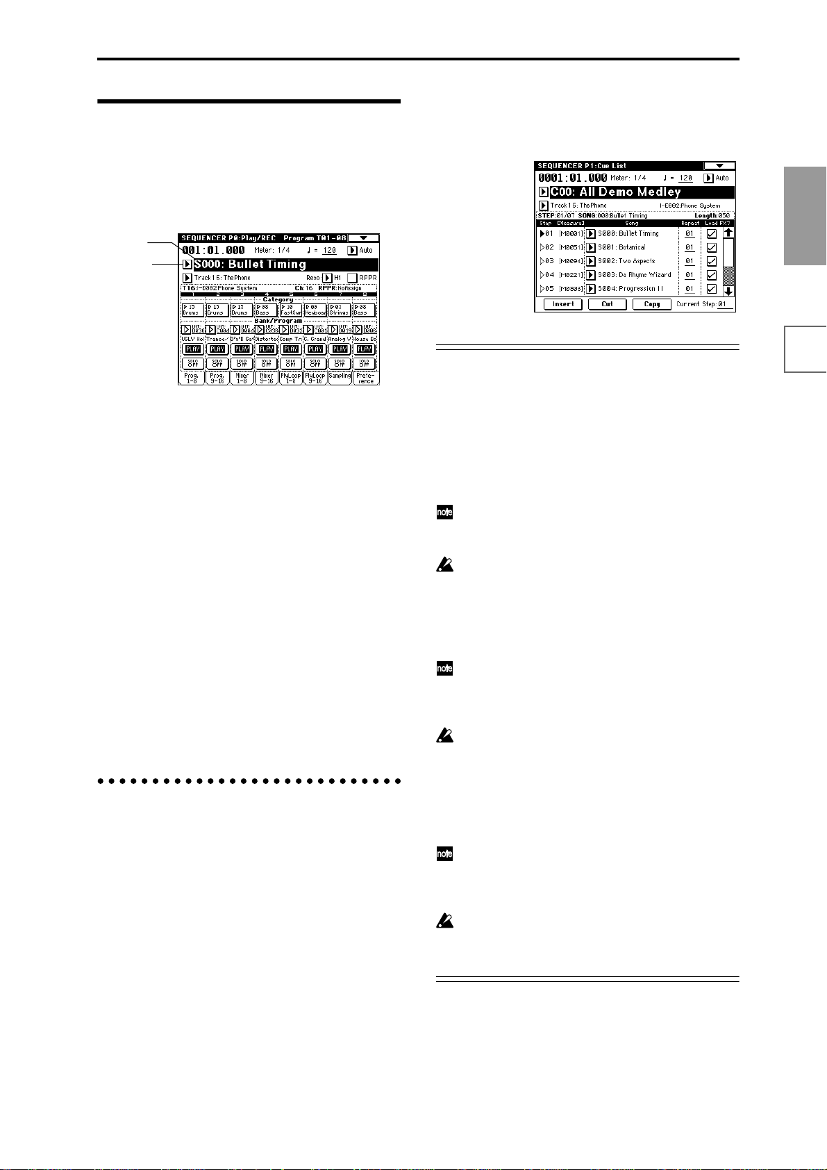
2. Selecting and playing a demonstration song in Sequencer
mode
1 Press the [SEQ] key (the LED will light).
You will enter Sequencer mode.
Song
Select
Popup
button
2 Access the P0: Play/REC, Program T01–08 page.
If this is not already displayed, press the [EXIT] key
and then press the Prog. 1–8 tab.
3 Select the demonstration song that you want to play
back.
Press the “Song Select” area to highlight the song
name.
Use the numeric keys to input a song number, and
press the [ENTER] key.
For example to select the second song, press numeric
key [1] and then press the [ENTER] key. (Song “S001”
will be selected.)
Alternatively, you can select a song from the popup
menu.
Press the “Song Select” popup button to access the
popup menu. In the popup menu, press the song that
you want to play back. The popup menu will close,
and the selected song will be displayed.
4 Press the SEQUENCER [START/STOP] key.
The LED will blink and the selected song will play.
5 If you wish to stop playback, press the SEQUENCER
[START/STOP] key once again.
Playing a cue list
Here’s how to playback the demonstration cue list. A cue
list allows you to playback multiple songs in succession,
and specify the number of times that each song will be
repeated.
1 Press the [MENU] key.
The LCD screen will show a list of the pages in
Sequencer mode.
2 Press either “P1: Cue List” or numeric key [1].
The P1: Cue List page will appear.
3 Press the SEQUENCER [START/STOP] key.
4 To stop playback, press the SEQUENCER [START/
STOP] key once again.
If the last step is End, playback will stop automatically
when it reaches that point. If the last step is Continue
to Step01, playback will return to the first step and
continue.
Contents of the disk
The internal hard drive contains the following data.
The included TNSFD-00P floppy disk contains the same
data as the PRELOAD.PCG file in the internal hard drive.
PRELOAD.PCG
• Preloaded data (programs, combinations, drum kits,
arpeggio patterns, global settings)
• Program data (programs using the sampling function)
used by the demonstration songs
When you load PRELOAD.PCG, it will be written
into internal memory. This data is preserved even if
the power is turned off.
When you load PRELOAD.PCG, the data existing in
the TRITON STUDIO before loading this data will be
replaced. If you wish to keep this data, you must first
save it before loading PRELOAD.PCG. (☞p.59)
PRELOAD.SNG
• Demonstration song and demonstration cue list data
When you load PRELOAD.SNG, it will be written
into internal sequencer memory. This memory is volatile, and the data will be lost when the power is
turned off.
Whether or not previously-written data will be
erased when you load PRELOAD.SNG is determined
by the “Select .SNG Allocation” setting. Refer to step
8 of the procedure on p.20.
PRELOAD.KSC
• Sample program data used by the demonstration
songs
When you load PRELOAD.KSC, its multisample/
sample data will be written into the TRITON STUDIO’s sample memory (RAM). This data will be lost
when the power is turned off.
Whether or not previously-written data will be
erased when you load PRELOAD.KSC is determined
by the “Select .KSC Allocation” setting. Refer to step
8 of the procedure on p.20.
Quick Start
Power on/offDemo songPlaying
programs
Playing
combinations
Using
controllers
ArpeggiatorRPPRProgram
editing
editing
Combination
SamplingSong
21
Page 30
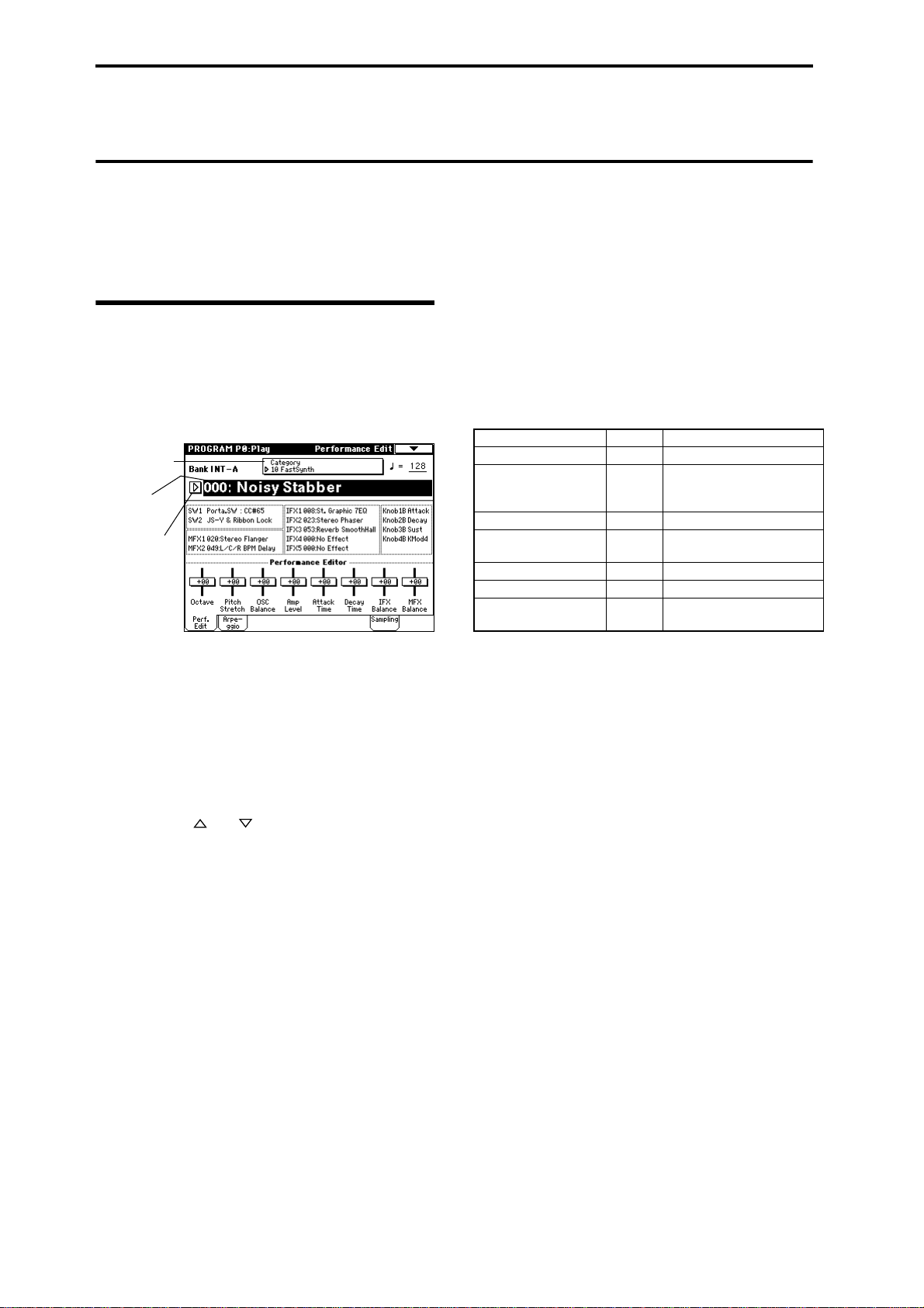
Selecting and playing a program
In Program mode you can select and play a program from
banks INT-A–EXB-G. Here we will show how to select
preset programs.
Try selecting various programs and hear how they sound.
Selecting a program
1 Press the [PROG] key (the LED will light).
You will enter Program mode. Make sure that the
upper line of the LCD screen indicates “PROGRAM P0:
Play.”
If this is not selected, press the [EXIT] key.
Category
popup button
Program
Select
Popup button
Selecting the program bank
In Program mode, you can switch banks to select programs from another bank.
With the factory settings, banks INT-A–INT-D contain
preloaded programs, and banks G, g(1)–G(9), and g(d)
contain preset programs. (☞table below)
5 Press a PROG BANK [INT-A]–[EXB-G] key to select a
bank.
The LED will light, and the selected bank will be displayed in the left of the LCD screen. For example to
select bank INT-B, press the BANK [INT-B] key. (The
[INT-B] key’s LED will light, and the upper left of the
LCD screen will indicate Bank INT-B.)
Bank Prog. No. Explanation
INT-A...INT-D (I-A...I-D) 000...127 Preloaded programs (☞VNL)
INT-E (I-E) 000...127 User programs (e.g., pro-
grams that use samples you
created)
INT-F (I-F) 000...127 EXB-MOSS programs
G 001...128 GM2 basic programs
(☞VNL)
g(1)...(9) (☞VNL) GM2 variation programs
g(d) (☞VNL) GM2 drum programs
EXB-A...EXB-H (E-A...E-H) 000...127 User programs, EXB-PCM
series programs
Selecting a program number
2 Make sure that “Program Select” is selected.
If this is not selected, press “Program Select” to highlight it.
3 Use the VALUE controllers to select the program that
you wish to play.
Y ou can use the following methods to select a program.
• Turn the [VALUE] dial.
• Press the [ ] or [ ] key.
• Use numeric keys [0]–[9] to specify the number,
and press the [ENTER] key.
4 Audition the sound.
Play a note on the keyboard to hear the sound you
selected.
Try operating various controllers to hear how the
sound will change. (☞p.25)
INT-A...INT-D
With the factory settings, these banks contain a wide
variety of preloaded programs that use the internal
PCM ROM multisamples, effects, and arpeggio patterns.
INT-E
This bank is used to store programs that you created,
for example from samples that you created.
INT-F
This can be selected only if the EXB-MOSS option is
installed. If the option is not installed, INT-F cannot be
selected.
G, g(1)...g(9), g(d)
These banks contain 128 capital programs, 128 variation programs, and 9 drum programs, all compatible
with the GM sound map. The programs of these banks
are all read-only. These programs are preset programs.
Each time you press the [G] key, the bank will change
in the following order.
G→g(1)→g(2)→g(3)→g(4)→g(5)→g(6)→g(7)→g(8)→
g(9)→g(d)→G...
(The LED will light, and the corresponding bank G,
g(1)–g(9), g(d) will be displayed in the upper left of the
LCD screen.)
EXB-A...EXB-G
With the factory settings, these banks do not contain
programs. These banks are used to load programs for
the EXB-PCM series options, or they can be used to
hold programs that you create.
128 programs can be written or rewritten to each bank
INT-A–INT-E, EXB-A–EXB-G (for a total of 1,536).
☞ For details of the program names etc., refer to “VNL”
(Voice Name List).
22
Page 31
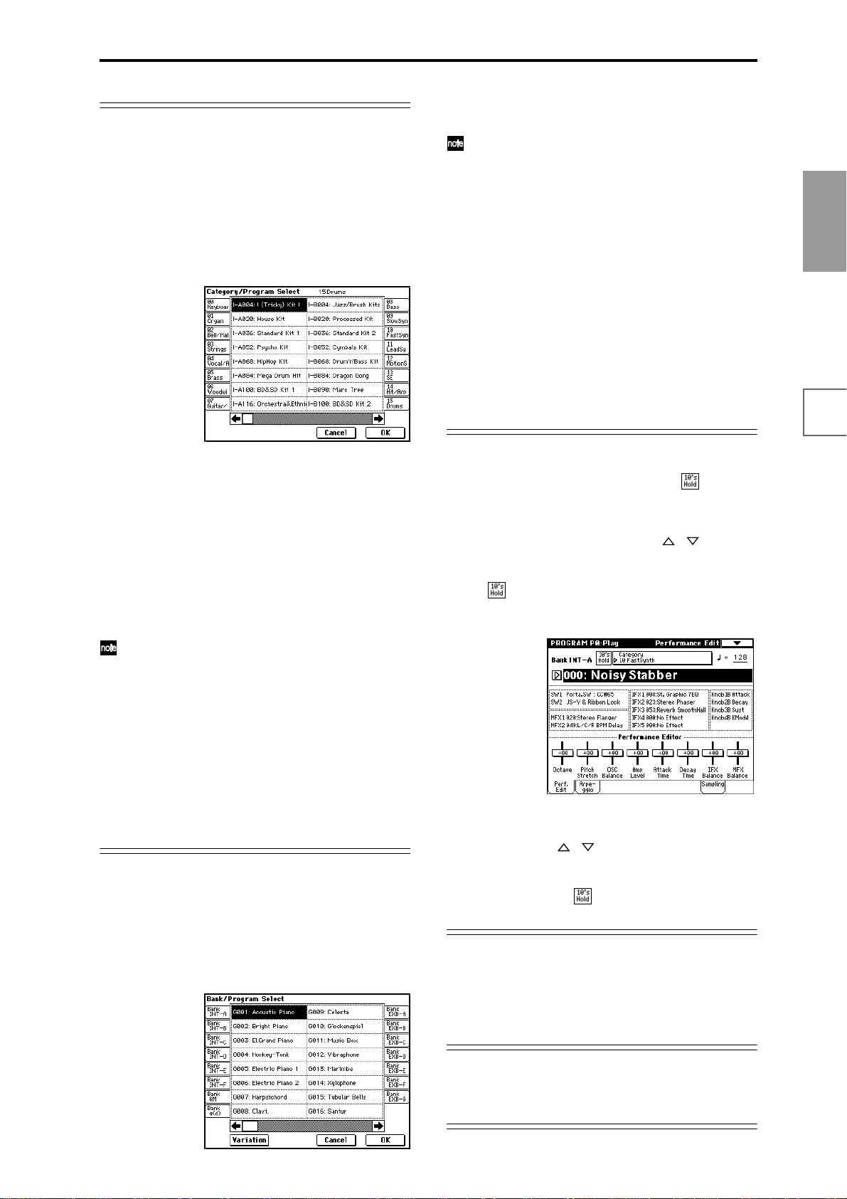
Selecting programs by category
You can select programs by category such as keyboard,
organ, bass, and drums.
With the factory settings, the preloaded programs and
preseted program are organized into sixteen categories.
You can choose a category, and then select from the programs in that category.
1 Press the Category popup button.
A tabbed “Category/Program Select” popup menu
will appear.
In the above graphic, category 15: Drums is selected.
The center area shows the programs contained in that
category.
2 Press the tabs located at the left and right to select a
different category.
The name of the selected category will be displayed in
full in the upper right.
3 Press a program name in the center area to select a
program.
The selected program will be highlighted.
If you wish to change a program to be in a different
category, you can choose the new category in the dialog box when writing the program (☞p.56). Category
names can be changed in “Category Name” (Global
P4).
4 When you are satisfied with the selected program,
press the OK button to close the popup menu.
If you press the Cancel button, the selection you made
here will be discarded, and you will return to the program that had been selected before you opened the
popup menu.
Selecting programs from the “Program Select”
popup menu
Y ou can select programs from a list or ganized by program
bank.
1 Press the “Program Select” popup button.
A tabbed “Bank/Program Select” popup menu will
appear.
In the graphic, bank G is selected. The center area
shows the programs contained in that bank.
The Variation button will be displayed only when
bank G is selected. Each time you press this button,
the bank will change in the order of
G→g(1)→g(2)...g(8)→g(9)→G...
2 Press the tabs located at the left and right to select
banks.
3 Press program names in the center area to select pro-
grams.
The selected program will be highlighted.
4 When you are satisfied with the selected program,
press the OK button to close the popup menu.
If you press the Cancel button, the selection you made
here will be discarded, and you will return to the program that had been selected before you opened the
popup menu.
Using 10’s HOLD to select programs
If you press the [./10’s HOLD] key to turn on the 10’s
Hold function (the LCD screen will indicate ), the ten’s
place of the program number will be fixed, and you will
be able to switch programs simply by pressing a single
numeric key . Each time you press a numeric key, the one’s
place will change. You can also use the [ ][ ] keys to
change the value of the ten’s place.
1 Press the [./10’s HOLD] key to make the display indi-
cate .
The ten’s place of the program number will be held
(fixed).
2 By pressing a numeric key [0]–[9], you can input the
one’s place in a single action.
3 You can use the [ ][ ] keys to change the value of
ten’s place.
4 To cancel the 10’s HOLD function, press [./10’s
HOLD] to erase the
display.
Using a connected switch to select programs
An optional on/off-type switch (such as the Korg PS-1)
can be connected to the rear panel ASSIGNABLE
SWITCH jack, and assigned a program select function.
(☞p.125)
Quick Start
Power on/offDemo songPlaying
programs
Playing
combinations
Using
controllers
ArpeggiatorRPPRProgram
editing
editing
Combination
SamplingSong
Selecting programs from a MIDI device
MIDI program change messages can be transmitted from
an external MIDI device, and received by TRITON STUDIO to select programs.(☞PG p.260)
23
Page 32
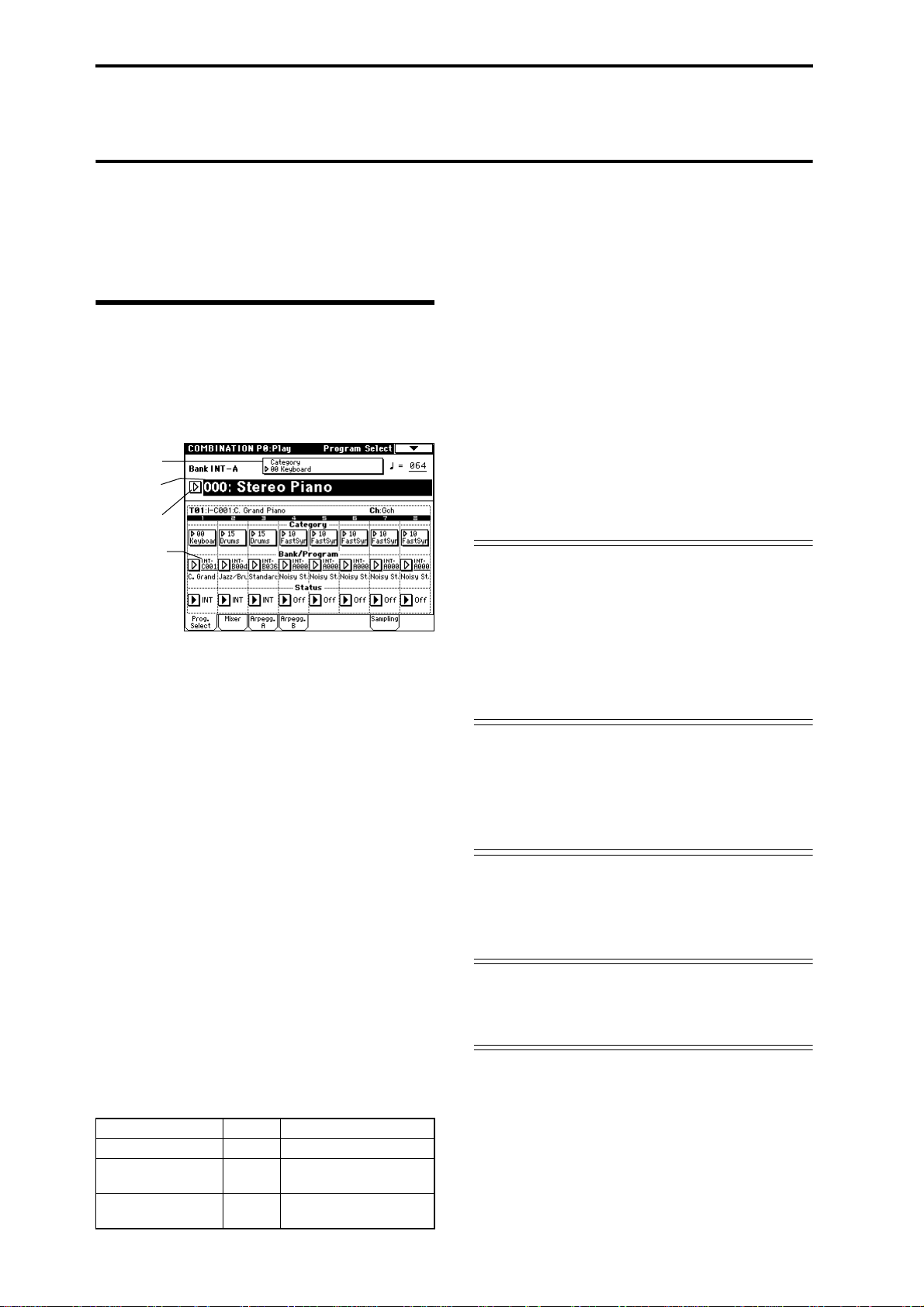
Selecting and playing a combination
In Combination mode you can select and play a combination from banks INT-A–EXB-G.
Try selecting various combinations and hear how they
sound.
Selecting a combination
1 Press the [COMBI] key (the LED will light).
You will enter Combination mode. Make sure that the
upper line of the LCD screen indicates “COMBINATION P0: Play.”
If this is not selected, press the [EXIT] key.
Category
popup button
Combination
Select
Popup button
Bank/Program
(Program Select)
Selecting a combination number
2 Make sure that “Combination Select” is selected.
If this is not selected, press “Combination Select” to
highlight it.
3 Use the VALUE controllers to select the combination
that you wish to play.
“Selecting a program” ☞p.22 3
4 Audition the sound.
Play a note on the keyboard to hear the sound you
selected.
Try operating the various controllers and listen to how
the sound changes. (☞p.25)
Selecting the combination bank
In Combination mode, you can switch banks to select
combinations from another bank.
With the factory settings, banks INT-A–INT-D contain
combinations. (☞table below)
5 Press a COMBI BANK [INT-A]–[EXB-G] key to select
a bank.
The LED will light, and the selected bank will be displayed in the left of the LCD screen. For example to
select bank INT-C, press the BANK [INT-C] key. (The
[INT-C] key will light, and the upper left of the LCD
screen will indicate Bank INT-C.)
Bank Prog. No. Explanation
INT-A...INT-D (I-A...I-D) 000...127 Preloaded combinations
INT-E (I-E) 000...127 User combinations, EXB-
EXB-A...EXB-G 000...127 User combinations, EXB-
MOSS combinations
PCM series combinations
INT-A...INT-D
With the factory settings, these banks contain a wide
variety of preloaded combinations that use multiple
programs, effects, and arpeggio patterns.
INT-E
With the factory settings, this bank does not contain
combinations. This bank can be used to load combinations that use programs of the EXB-MOSS option, or to
store combinations that you created.
EXB-A...EXB-G
With the factory settings, these banks do not contain
combinations. These banks can be used to load combinations that use programs of the EXB-PCM option
boards, or to store combinations that you have created.
128 programs can be written or rewritten to each bank
INT-A–INT-E, EXB-A–EXB-G (for a total of 1,536).
☞ For details of the combination names etc., refer to
“VNL” (Voice Name List).
Selecting combinations by category
You can select combinations from any of the sixteen categories in the same way as for programs.
With the factory settings, all the preloaded combinations
are organized into sixteen categories. You can choose a
category, and then select from the combinations in that
category.
“Selecting programs by category” ☞p.23
Using 10’s HOLD to select combinations
You can fix the ten’s place of the combination number, so
that a combination can be selected simply by pressing a
numeric key once to change the one’s place.
“Using 10’s HOLD to select programs” ☞p.23
Using a connected switch to select combinations
An optional on/off type foot switch such as the Korg PS-1
can be connected to the rear panel ASSIGNABLE
SWITCH jack, and used to select combinations. (☞p.125)
Selecting combinations from a MIDI device
MIDI program change messages can be transmitted from
an external MIDI device, and received by TRITON STUDIO to select combinations. (☞PG p.260)
24
Page 33

Using controllers to modify the sound
+
The TRITON STUDIO provides various controllers – a
joystick, the ribbon controller, the SW1 and SW2 switches,
and the REALTIME CONTROL [1], [2], [3], [4] knobs –
that let you modify the tone, pitch, volume, or effects in
realtime while you play.
Each time you select a program or combination, try out
these controllers to hear how they affect the sound.
Tonal changes etc. produced by these controllers can
be recorded on the internal sequencer or on an external MIDI sequencer.
Joystick
+Y+Y
−X−X +
X+X
Ribbon controller
−X−X ++X+X0
Move your finger to the left and right on the ribbon controller to apply an effect.
Normally, this is used to control pitch, volume or filter etc.
Y ou can use the Lock function of [SW1] or [SW2] keys
to hold the effect even after you release your finger
from the ribbon controller . For the pr ocedur e, refer to
“The Lock function” on the following page.
You can use the ribbon controller as a source for alternate modulation or effect dynamic modulation, to
control program parameters or effect parameters.
Quick Start
Power on/offDemo songPlaying
programs
Playing
combinations
−Y
JS(+X): Move the joystick toward the right to apply an
effect. Normally this is used to control the pitch
(bend up).
JS(–X): Move the joystick toward the left to apply an
effect. Normally this is used to control the pitch
(bend down).
JS(+Y): Move the joystick away from yourself to apply
an effect. Normally this is used to control the
oscillator LFO (vibrato).
JS(–Y): Move the joystick toward yourself to apply an
effect. Normally this is used to control filter
LFO (wah).
Y ou can use the Lock function of [SW1] or [SW2] keys
to hold the effect in the current position of the joystick. For the procedure, refer to “The lock function”
on the following page.
Y ou can use the joystick as a source for alternate modulation or effect dynamic modulation, to control program parameters or effect parameters.
SW1, SW2
Y ou can use these keys as sources for alternate modulation
or effect dynamic modulation to control program parameters or effect parameters.
These switches can also be used to switch the octave, to
turn portamento on/off, or to lock the position of the ribbon controller or after touch lock function (☞p.26).
You can specify the way in which the [SW1] and [SW2]
keys will operate: either Toggle, when the assigned func-
tion will be switched between on and off each time the
key is pressed, or Momentary, when the assigned function
will be active on only as long as you hold down the
switch.
In Program mode, the function of the [SW1] and
[SW2] keys can be checked in the P0: Play, Performance Edit page. (☞p.27)
When you write a program or combination, the on/
off status of the [SW1] and [SW2] keys is saved.
For details on making these settings, refer to “Setting
the function of [SW1] and [SW2]” (☞p.145).
Using
controllers
ArpeggiatorRPPRProgram
editing
editing
Combination
SamplingSong
25
Page 34

The Lock function
Joystick
1 Select program bank INT-A001: Acoustic Piano, and
play the keyboard.
T o select a program, make sure that you are in Pr ogram
mode, and press the BANK [INT-A] key, numeric key
[1], and then the [ENTER] key.
2 Move the joystick toward yourself (the –Y direction).
The modulation will deepen, and at the same time, resonance will be applied to give a unique character to the
sound.
3 While holding the joystick toward yourself, press the
[SW2] switch (The [SW2] key LED will light).
The modulation effect at this point will be maintained.
(Lock function)
The Lock function can also be applied to aftertouch. If
the [SW1] or [SW2] switch is assigned to After Touch
Lock, the effect produced by pressing down on the
keyboard can be held by turning on the [SW1] or
[SW2] switch. For details on the [SW1] and [SW2]
switch functions, refer to PG p.249.
REALTIME CONTROLS [1], [2], [3], [4]
These knobs can be used to control the filter cutoff frequency and resonance, the amp and filter EG, volume,
portamento time, pan, pitch LFO, or the send levels to the
master effects, etc.
1 Press the [REALTIME CONTROLS] key to
switch the function of the realtime controllers to Amode or B-mode.
Each time you press the key , A-mode or B-mode will be
alternately selected, and the corresponding LED will
light.
4 Release the joystick, and play the keyboard.
The modulation will stay the same as it was when the
[SW2] key was pressed. Moving the joystick toward
yourself will not affect the sound.
5 Press the [SW2] key once again to release the Lock
function.
Ribbon controller
Make sure that the INT-A001: Acoustic Piano program is
selected.
1 Press the [SW2] key. (The [SW2] key LED will light.)
2 Touch the ribbon controller, and move your finger to
left and right.
Movement in the +X direction will brighten the tone,
and movement in the –X direction will darken the tone.
3 Take your finger away from the ribbon controller.
The sound will remain as it was before you removed
your finger. (Lock function)
4 Press the [SW2] key once again to release the Lock
function.
In the LCD screen, SW2 indicates JS–Y & Ribbon
Lock. This means that the [SW2] key is assigned to
control the Lock function for the joystick –Y direction
and the ribbon controller (☞PG p.249). The key will
operate in Toggle mode.
If you move the joystick in the –Y direction, press the
[SW2] key to turn on the Lock function, then operate
the ribbon controller, and finally release both controllers, the sound you modified by the two controllers
will be maintained.
In many programs and combinations, the [SW2] key
is assigned to control the Lock function for the joystick –Y direction and the ribbon controller.
2 Rotate the desired knob to control the sound, etc.
A-mode controls
In A-mode, knobs [1]–[4] will control/edit the following
functions.
Placing the knobs in the center (12 o’clock) position
will produce the values specified by the program
parameters.
Knob [1]: LPF CUTOFF
Adjusts the cutoff frequency of the low pass filter.
When you adjust the cutoff frequency of the filter, the
brightness of the sound will change. The effect will
depend on the settings of the program parameters, but
normally , r otating the knob toward the left will darken the
sound, and rotating it toward the right will brighten it.
Level
LPF
Frequency
Cutoff
frequency
Knob [2]: RESONANCE/HPF
Adjust the resonance level of a low pass filter or the cutoff
frequency of a high pass filter.
The content that is controlled will depend on the filter
type specified by the program.
By adjusting the filter resonance level, you can increase or
decrease the resonance level to add a unique character to
the sound.
HighLow
26
Page 35

Adjusting the cutoff frequency of the high-pass filter will
modify the fullness of the sound from which the low frequency range has been filtered out.
Level
LPF HPF
Cutoff
frequency
Knob [3]: EG-INTENSITY
Adjust the filter EG intensity (the depth at which the filter
EG is applied).
Rotating the knob will affect the depth of the filter EG.
Normally, rotating the knob toward the left will make the
filter EG apply less deeply , and rotating it toward the right
will make the filter EG apply more deeply. Since the filter
EG will operate based on the cutoff frequency of the filter,
knobs [1] and [3] will work together to control the tonal
changes produced by the filter.
Level
Time
Viewing the parameters that are assigned to
[SW1], [SW2] keys, and the REALTIME CONTROLS
B-mode
In Program mode, the B-mode functions of the REALTIME CONTROLS knobs [1], [2], [3], and [4] and [SW1]/
[SW2] keys can be verified in the P0: Play, Performance
Edit page.
Functions assigned to
the B-mode knobs [1]–[4]
Functions assigned to the
[SW1] and [SW2] keys
[VALUE] slider
When a program number is selected in Program P0: Play
page, or when a combination number is selected in Combination mode page P0: Play page, you can use the
[VALUE] slider as a source for alternate modulation or
effect dynamic modulation, and control program parameters or effect parameters.
Quick Start
Power on/offDemo songPlaying
programs
Playing
combinations
Using
controllers
ArpeggiatorRPPRProgram
Knob [4]: EG-RELEASE
Adjusts the release times of the filter EG and the amp EG.
This will determine the amount of time from note-off until
the sound disappears.
When you adjust the knob, the release times of the filter
EG and the amp EG will change. Normally, rotating the
knob toward the left will shorten the release time, and
rotating it toward the right will lengthen the release time.
note-on
Level
Attack Level
Decay Time
Attack Time
Start Level
Break Level
Sustain Level
Slope Time
note-off
Release Level
Release Time
Time
B-mode controls
Using these knobs, you can control parameters such as
volume, portamento time, pan or filter and amp EG, pitch
LFO, and master effect send levels etc.
The B-mode function settings are made for each individual program, combination, or song.
In Sampling mode and Song Play mode, the B-mode functions are set for the entire mode (☞p.145).
Keyboard
Velocity
The force with which you initially strike a note can apply
an effect.
Normally this is used to control volume, or the speed or
sensitivity of the EG.
After Touch
This effect can be applied by varing the pressure on a key
that is already being held down.
Normally this is used to control volume, tone (cutoff frequency), or LFO sensitivity etc.
Note Number
Varing amounts of an effect will be applied depending on
the position of the key on the keyboard.
Normally this is used to control volume, tone (cutoff frequency), LFO sensitivity, and EG sensitivity etc.
This can be used as a source for alternate modulation
or effect dynamic modulation, to control program
parameters or effect parameters.
editing
editing
Combination
SamplingSong
27
Page 36

Foot pedals/Switch
Damper Pedal
An optional switch-type damper pedal such as the Korg
DS-1H can be connected to TRITON STUDIO. If a DS-1H
is connected, it will function as a half-damper pedal. The
half-damper function cannot be controlled by other pedals.
Assignable Foot Switch
If an optional foot switch such as the Korg PS-1 is connected to the rear panel ASSIGNABLE SWITCH jack, an
assigned function can be switched on/off using the foot
switch.
The function of the foot switch is assigned in Global P2:
Controller “Foot SW Assign” (☞p.125).
Assignable Foot Pedal
An optional expression pedal such as the Korg EXP-2 foot
controller or Korg XVP-10 EXP/VOL pedal can be connected to the rear panel ASSIGNABLE PEDAL jack, and
used to apply an effect.
The function of the foot pedal is assigned in Global P2:
Controller “Foot Pedal Assign” (☞p.125).
ARPEGGIATOR [TEMPO] knob, [GATE] knob, [VELOCITY] knob
These knobs control the arpeggiator in realtime. For
details on operation, refer to the following page.
28
Page 37

Using the arpeggiator while you play
The arpeggiator is a function that automatically generates
arpeggios (broken chords). Most arpeggiators produce an
arpeggio when you play a chord on the keyboard.
The chord you played on
the keyboard is sounded as
an arpeggio (broken chord)
In addition to this, the TRITON STUDIO’s arpeggiator is a
polyphonic arpeggiator that is able to produce a variety of
chordal transformations or phrases based on the pitch or
timing of the notes you play on the keyboard. These functions let you use the arpeggiator to play a wide range of
patterns including drum or bass phrases, and guitar or
keyboard backing riffs. It is also effective to use the arpeggiator as part of the sound-creating process when creating
subtly-moving pads, synth-sounds, or sound effects.
The TRITON STUDIO features a Dual Arpeggiator that
lets you simultaneously use two arpeggio patterns in
Combination mode, Sequencer mode, and Song Play
mode. You can take advantage of this in many ways, such
as applying separate arpeggio patterns to a drums program and a bass program, or using a keyboard split or
velocity to switch between two arpeggio patterns.
The TRITON STUDIO provides five preset arpeggio patterns (the standard UP, DOWN, ALT1, ALT2, and RAN-
DOM), and lets you program and store 507 user arpeggio
patterns. With the factory settings, these contain a wide
variety of preloaded user arpeggio patterns (☞VNL). An
arpeggio pattern that you create can also be stored as a
user arpeggio pattern (☞p.134).
Using the arpeggiator in Program mode
1 Press the [PROG] key to enter Program mode, and
select a program. (“Selecting and playing a program”
☞p.22)
As you select various programs, you will notice that
the ARPEGGIATOR [ON/OFF] key LED will light for
some programs. (“Linking the arpeggiator to program,
combinations” ☞p.32) When you press the keyboard,
the arpeggiator will start.
For other programs, you can press the ARPEGGIA T OR
[ON/OFF] key (the LED will light) to turn on the
arpeggiator. Arpeggios will begin sounding when you
play the keyboard.
2 As described in the following sections “Settings
using controllers” and “Settings in the LCD screen,”
move the controllers or modify the parameters to
change the way in which the arpeggios are played.
Settings using controllers
Arpeggiator on/off
Each time you press the ARPEGGIATOR [ON/OFF]
key, the arpeggiator will be switched on/off.
When the arpeggiator is turned on (the LED will light)
and the selected arpeggio pattern will begin sounding
when you play the keyboard.
Quick Start
Power on/offDemo songPlaying
programs
Playing
combinations
Using
controllers
ArpeggiatorRPPRProgram
editing
editing
Combination
The on/off status is saved when you write each program.
In Combination, Song, and Song Play mode, depending on the arpeggiator A, B settings, the arpeggio may
not start when you press the ARPEGGIATOR [ON/
OFF] key to turn it on (☞p.31).
Adjusting the arpeggiator tempo
Rotate the ARPEGGIATOR [TEMPO] knob to adjust
the tempo.
The “ =” display in the upper right of the LCD will
change. The tempo can be adjusted over a range of 40–
240. Y ou can also set the tempo by selecting “ =,” using
numeric keys [0]–[9] to enter a tempo, and pressing the
[ENTER] key. The tempo can also be set by the
[VALUE] slider, [VALUE] dial, or [ ][ ] keys. The
LED will blink in time with the specified tempo.
The knob setting is saved when you write each program.
SamplingSong
29
Page 38

The arpeggio playback speed is affected by the
“Reso” setting (Program P0: Play, Arpeggio page), or
“Resolution” (P7: Edit-Arpeggiator, Arpeg. Setup
page).
If “MIDI Clock” (Global P1: MIDI) is set to External
MIDI or External mLAN, the display will indicate
“ =” EXT. The tempo will be synchronized to an
external MIDI device, and it will not be possible to
adjust the tempo on the TRITON STUDIO.
Adjusting the length of the arpeggiated
notes
Rotate the ARPEGGIATOR [GATE] knob to adjust
the length of the arpeggiated notes.
Rotating the knob toward the left will shorten the
duration of the notes, and rotating it toward the right
will lengthen the duration of the notes. At the center
position (12 o’clock), the note length will be as specified by the program parameter “Gate” (Program P7:
Edit-Arpeggiator, Arpeg. Setup page).
The knob setting is saved when you write each program.
It is effective to control this function in conjunction
with the REALTIME CONTROLS A-mode knob [4]
(EG RELEASE).
Adjusting the strength of the arpeggio notes
Rotate the ARPEGGIATOR [VELOCITY] knob to
adjust the strength of the arpeggio notes.
Rotating the knob toward the left will make the notes
softer, and rotating the knob toward the right will
make the notes stronger. At the center position (12
o’clock), the velocity will be as specified by the program parameter “Velocity” (Program P7: Edit-Arpeg-
giator, Arpeg. Setup page).
The knob setting is saved when you write each program.
It is effective to control this function in conjunction
with the REALTIME CONTROLS A-mode knobs [1]
(LPF CUTOFF), [2] (RESONANCE/HPF), and [3]
(EG- INTENSITY).
Settings in the LCD screen
Selecting an arpeggio pattern
An arpeggio pattern can be selected from preset arpeggio
patterns P000–P004 and user arpeggio patterns U000(I-A/
B)–U506(User). With the factory settings, U000(I-A/B)–
U199(I-A/B), U312(User)–U506(User) contain a wide variety of preloaded user arpeggio patterns. For the arpeggio
pattern names (☞VNL).
Choose “Pat (Pattern Select),” and use the [VALUE]
slider, [VALUE] dial, [ ][ ] keys, and popup menu
to select an arpeggio pattern.
User arpeggio patterns can also be selected by using
the numeric keys [0]–[9] to input the pattern number
and then pressing the [ENTER] key. (☞p.130)
Changing the note value of the arpeggiated
notes
The “Reso (Resolution)” parameter in the LCD screen lets
you set the note value of the arpeggiated notes, over a
range from 3 – .
Press “Reso,” and use the [VALUE] slider, [VALUE]
dial, [ ][ ] keys, or popup menu to select the
desired arpeggio note interval.
Selecting the octave range in which the
arpeggio is sounded
Use the “Octave” radio buttons in the LCD screen to specify the range of octaves in which the arpeggio will be
sounded (☞p.131).
Press an “Octave” radio button to make your selection.
Sounding an arpeggio in the order of the
pitches in the chord you played
You can select whether the notes of the arpeggio will be
sounded in the order of the pitches in the chord you
played (regardless of the order in which you actually
played the notes), or in the order in which you played the
notes.
Press the “Sort” check box in the LCD screen to make
this setting.
Checked: the arpeggio will sound each note in the
order of its pitch, regardless of the order in which you
actually played the notes.
Unchecked: the arpeggio will sound each note in the
order in which you actually played the notes.
In Program P0: Play, press the Arpeggio tab.
30
Setting the arpeggio to continue playing
even after you have taken your hand off the
keyboard
Y ou can select whether the arpeggio will continue playing
when you take your hand off the keyboard, or whether
the arpeggio will stop.
Press the “Latch” check box in the LCD screen to
make this setting.
Checked: The arpeggio will continue playing even
after you remove your hand from the keyboard.
Unchecked: The arpeggio will stop playing when you
remove your hand from the keyboard.
Page 39

Synchronizing the arpeggiator to your keyboard timing
You can specify whether the arpeggio will begin at the
moment you play the keyboard, or whether it will always
play in synchronization to the MIDI clock tempo.
Press the “Key Sync.” check box in the LCD screen to
make this setting.
Checked: When you take your hand completely off of
the keyboard and then play the first note-on, the arpeggio pattern will start from the beginning. This setting is
suitable when you want the arpeggio to start from the
beginning of the measure as you are playing in realtime.
Unchecked: The arpeggio will always be synchronized
to the MIDI clock tempo.
Sounding both the arpeggio notes and the
notes you play
Press the “Keyboard” check box to make this setting.
Checked: The notes you play on the keyboard and the
notes played by the arpeggiator will both sound.
Unchecked: Only the arpeggiated notes will sound.
Using the arpeggiator in Combination mode
In Combination mode the TRITON STUDIO provides
dual arpeggiators, allowing you to run two arpeggio patterns simultaneously.
1 Press the [COMBI] key to enter Combination mode,
and select a combination. (“Selecting and playing a
combination” ☞p.24)
As you select various combinations, you will notice
that the ARPEGGIA T OR [ON/OFF] key LED will light
for some combinations. (“Linking the arpeggiator to
program, combinations” ☞p.32) When you press the
keyboard, the arpeggiator will start.
For other combinations, you can press the ARPEGGIATOR [ON/OFF] key (the LED will light) to turn on the
arpeggiator.
2 As described in the preceding section “Settings using
controllers” and the following section “Settings in
the LCD screen,” move the controllers or modify the
parameters to change the way in which the arpeggios
are played.
The ARPEGGIA TOR [ON/OFF] key, ARPEGGIA TOR
[TEMPO] knob, ARPEGGIATOR [GATE] knob, and
ARPEGGIATOR [VELOCITY] knob will apply to
both arpeggiators A and B. Their state is saved when
the combination is written.
Quick Start
Power on/offDemo songPlaying
programs
Playing
combinations
Using
controllers
Settings in the LCD screen
In Combination P0: Play, press the Arpegg. A tab.
Timbre Assign
Select the arpeggiator(s) that will run
Use the “Arpeggiator Run” check boxes to specify the
arpeggiator(s) that you want to have running. The arpeggiator(s) that are checked here will operate when the
ARPEGGIATOR [ON/OFF] key is on. However, the
arpeggiator will play a timbre only if the table displayed
next to the check boxes assigns arpeggiator A or B to a T
(timbre) 1–8. These settings are made in Combination P7:
Edit-Arp., Setup page “Arpeggiator Assign” (☞p.132).
Arpeggiator-A, Arpeggiator-B
For each arpeggiator A and B, you can make settings for
“Pat (Pattern Select),” “Reso (Resolution),” “Octave,”
“Sort,” “Latch,” “Key Sync,” and “Keyboard.” (☞p.130)
ArpeggiatorRPPRProgram
editing
editing
Combination
SamplingSong
31
Page 40

Checking the structure of a user arpeggio
pattern
Let’s see how combination INT-B097: Try Some Tekno is
constructed.
Select combination INT-B097: Try Some Tekno, and
look at the Arpeggio Play A page and Arpeggio Play
B page.
Other settings for the arpeggiator
You can also set “Gate,” “Velocity,” “Swing,” and “Scan
Zone.” These parameters are set in Program P7: EditArpeggiator, Arpeg. Setup Page, Combination P7: EditArp., Arpeggiator A, B page. (☞p.131).
Linking the arpeggiator to program, combinations
You can specify whether the arpeggiator settings written
in a program or combination will also be selected when
you switch programs or combinations, or whether the
arpeggiator status will not change when you switch programs or combinations.
With the factory settings, the former is selected. Use the
latter when you want to keep the same arpeggio pattern
running, and change only the program sound.
This setting is made in “Auto Arpeggiator” (Global P0:
Basic Setup, Basic page).
Creating a user arpeggio pattern
Arpeggio patterns that you create can be written to U000
(I-A/B)–U506 (User).
These can be created in Global P6: User Arpeggio
(☞p.134).
• As you can see from the “Timbre Assign” table,
arpeggiator A is assigned to timbre 7 and 8, and
arpeggiator B is assigned to timbre 6.
When you play the keyboard the U453 (User): DrTechno arpeggio pattern will play the program INTC004: Trance/GrageKit of timbre 7 (Timbre 8 is a
dummy timbre used to operate Timbre 7. ☞p.133).
The P000: UP arpeggio pattern will play the program INT-C122: Synchro Science of timbre 6.
• If you uncheck “Arpeggiator Run A” or “Arpeggiator
Run B,” the unchecked arpeggiator will stop.
If you check it once again and play the keyboard, the
arpeggiator will begin running.
• Look at the Combination P7: Edit-Arp., Scan Zone A/
B page, and you will see that the A keys “Top Key”
and “Bottom Key” are set so that arpeggiator A will
operate only for keys B3 and lower, and that the B
“Top Key” and “Bottom Key” are set so that
arpeggiator B will operate only for keys C4 and
higher.
32
Page 41

Playing with the RPPR (Realtime Pattern
Play/Recording) function
TRITON STUDIO’s Sequencer mode provides an RPPR
(Realtime Pattern Play/Recording) function.
Using the RPPR function, each note of the keyboard can
be assigned to a preset pattern or user pattern and a track
that will play the assigned pattern. You can then playback
the assigned pattern in realtime (and record it, if desired)
simply by playing the corresponding note. (Preset patterns suitable for playing by the drum track are already
provided in the internal memory.)
Here we will explain how to use the RPPR function to
play a demo song.
1 Load the demo song data as described in “1. Loading
the demo song data in Disk mode” (☞p.20).
2 Press the [SEQ] key (the LED will light) to enter
Sequencer mode, and access the P0: Play/REC, Program T01–08 page.
3 In “Song Select,” select S005: Midnight Sun.
Select the song as described in “2. Selecting and playing a demonstration song in Sequencer mode” (☞p.21).
Shutdown Keys:
When you play a key in the range of C–1 – C2, the currently-playing pattern will stop.
Pattern Assignable:
A pattern and track can be assigned to each of the 72 keys
in the range of C#2–C8. If you do not assign a key, it can be
used to play as usual.
As in the example shown in the following diagram, you
can make one key play a drums pattern, another key a
bass phrase, and yet another key play guitar chords, all by
specifying a different pattern and track for each key.
88 Keys
76 Keys
61 Keys
C-1
Shutdown Keys
C-1 ... C2
Pattern Assignable
C#2 ... C 8
Quick Start
Power on/offDemo songPlaying
programs
Playing
G9
combinations
Using
controllers
4 Make sure that the “RPPR” check box is checked.
Checked: The specified RPPR (set in Sequencer P6: Pat-
tern/RPPR, RPPR Setup) will function.
Unchecked: RPPR will not function. Operation will be
as in normal Sequencer mode.
5 Press a key.
The pattern assigned to that key will playback.
In some cases, the pattern will continue playing after
you release your hand from the keyboard. You can stop
playback either by pressing that key again, or by pressing a key in the area of C2 or below.
Pattern P000 Track01 (Drums Program)
Pattern U000 Track02 (Bass Program)
Pattern P001 Track01 (Drums Program)
Pattern U001 Track02 (Bass Program)
Pattern U002 Track03 (Guitar Program)
ArpeggiatorRPPRProgram
editing
editing
Combination
SamplingSong
33
Page 42

Simple program editing
By operating the performance editor and the realtime controllers you can easily and intuitively modify the sound of
a program.
Program editing refers to the process of modifying the
parameters that make up a program, in order to modify
the sound or change the controller, effect settings etc.
More detailed editing can be performed in Program
P1: Edit-Basic – P9: Edit-Master Effect.
Performance Edit
By using the eight sliders of the Performance Editor, you
can make overall adjustments to the sound. When you
edit the setting, multiple program parameters are
adjusted simultaneously.
1 Press the [PROG] key (the LED will light) to enter
Program mode.
2 Press the Perf. Edit tab.
The Performance Edit page will appear.
Functions assigned to [SW1] and [SW2] keys
Type of Insert effect
For programs whose “Oscillator Mode” (Program
P1: Edit-Basic, Program Basic page) setting is Single,
oscillator 2 will not sound. Only the level of oscillator
1 will change. For a Drums program, this performance editor will have no effect.
• Amp Level: Indicates the amp level. This will adjust
the volume of the entire program.
• Attack Time: Indicates the attack time of the filter EG
and amp EG. This will adjust the speed of the attack
from note-on.
In order to maximize the effect of the Attack Time
adjustment, the amp EG Start Level, Attack Level,
Start Level Modulation, and Attack Time Modulation
parameters are also adjusted.
• Decay Time: Indicates the decay time and slope time
of the filter EG and amp EG.
• IFX Balance: This simultaneously adjusts the “Wet/
Dry” balance of all insert effect.
• MFX Balance: This simultaneously adjusts the Return
1 and 2 parameters of the master effects.
Depending on the settings of the program parameters, the result may not be noticeable.
Type of
Master effect
Performance
editor
Parameters assigned to B-mode
of the realtime editor
3 Select the Program.
4 Select the Performance Editor, and use the VALUE
controllers to edit the settings.
If you want to reset the value to the value saved with
the selected program, press numeric key [0] and then
press the [ENTER] key to restore the previous setting.
• Octave: Indicates the octave setting.
• Pitch Stretch: Simultaneously adjusts the transpose
and tune settings of the oscillator. This allows you to
produce a variety of tonal changes without losing the
character of the original sound.
This is particularly effective for acoustic-type programs such as guitar, bass, or piano. Select various
programs and try this out.
“Pitch Stretch” cannot be used with bank INT-F.
• OSC Balance: Adjusts the level balance between
oscillators 1 and 2.
Realtime controls
The REALTIME CONTROLS [1]–[4] knobs can be used to
edit parameters such as the filter cutoff frequency, resonance, the amp and filter EG, release, volume, portamento
time, pan, pitch LFO, and master effect send level etc.
(☞p.26).
If CC#70–79 are assigned to REALTIME CONTROLS
A-mode or B-mode, the sound edited by knobs [1]–[4]
can be saved by the Program Write operation.
Writing a program
The edited content will be lost if you select another
program or turn off the power before saving.
If you want to save the modified sound, select the
page menu command “Write Program,” and write the
program. (☞p.56)
It is best to write your own edited programs into an initial (initialized) program of bank INT-E or EXB-A–
EXB-G. You should also give a new name to the program you are writing.
If you want to overwrite the program using the same
program number, press the SEQUENCER [REC/
WRITE] key and then press the OK button.
34
Page 43

Simple combination editing
A combination is a set of multiple (up to eight) programs,
and allows you to create complex sounds that could not
be produced by a single program.
Combination editing refers to the process of modifying
the sound of a combination by changing the program
selected for each timbre or by adjusting each timbre’s keyboard range and velocity range, or by modifying the controller, and effect settings.
You can edit a combination in Combination P1: Edit-Program/Mixer–P9: Edit-Master FX, but can also make settings for “Program Select, “Pan,” and “Volume” in
Combination P0: Play as well.
An example of editing
As an example, here’s how to do some simple editing on
combination Bank INT-C086: Shiny DigiPiano.
1 Press the [COMBI] key (the LED will light) to enter
Combination mode.
2 Select INT-C086: Shiny DigiPiano.
Timbre 2
Timbre 1
Selecting the program for a timbre
3 Press the Prog. Select tab.
When a timbre’s “Status” is turned Off, the program
assigned to that timbre will not sound. If the “Status” is
set to INT, the program will sound. Try setting timbres
1 and 2 alternately to INT and Off, and listen to the
result.
Only timbre 1 will sound
Only timbre 2 will sound
After you have listened to the sound, set the “Status”
for timbres 1 and 2 to INT.
As an alternative to changing the “Status” setting,
you can select the page menu command “Solo
Selected Timbre” to hear the sound of an individual
timbre.
4 Now let’s change the program of timbre 2 to a differ-
ent program.
Press the timbre 2 “Bank/Program (Program Select)”
switch (it will be highlighted).
Quick Start
Power on/offDemo songPlaying
programs
Playing
combinations
Using
controllers
ArpeggiatorRPPRProgram
editing
This combination layers (simultaneously sounds) the
programs of timbre 1 and timbre 2. A typical electric
piano INT-D017: Pro-Stage EP is assigned to Timbre 1,
and a digital-type electric piano INT-D049: Classic
Tines is assigned to Timbre 2. These two programs are
layered to create a frequently-heard type of electric
piano sound.
A timbre consists a of program together with multiple parameters that control that program. A combination can use up to eight of these timbres.
Use the BANK [INT-A]–[EXB-G] keys, and VALUE
controllers to select a program.
Alternatively, you can select a program from a popup
menu. Press the popup button, and select the desired
program from the popup menu that appears.
5 You can also select programs by category. Press Cate-
gory popup button for timbre 2.
The “Category/Timbre2 Program” select menu will
appear. In this combination, a program from the “Keyboard” category is selected for both timbres 1 and 2.
editing
Combination
SamplingSong
35
Page 44
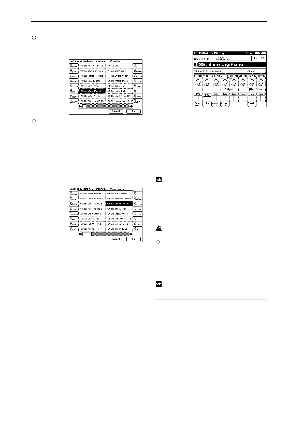
If you wish to select a different program from the
same category, press the desired program. That program will be highlighted. Press the scroll bar to see
other programs in the same category.
If you wish to select a program from a different category , press one of the tabs located to the left and right
to select the desired category. The full name of the
selected category will appear in the upper right.
Let’s select the 04: Vocal/Airy category.
Press the 04 Vocal/Airy electric tab, and then press the
desired program to select it. The program you pressed
will be highlighted. Press the scroll bar to see other
programs in the same category.
For this example, select INT-C027: Dream Voices. This
will produce a layered combination consisting of a
piano and voice.
Adjusting the stereo position
7 Press the Mixer tab.
8 Press “Pan” for timbre 2 (it will be highlighted), and
use the VALUE controllers to edit the setting.
With a setting of C064 the sound will be located in the
center. A setting of L001 places the sound at the far left,
and R127 at the far right. With a setting of RND, the
sound will move randomly between left and right each
time a note is played.
Adjusting the volume
9 Press “Volume” for timbre 2 (it will be highlighted),
and use the VALUE controllers to edit the setting.
If you check “Hold Balance” and adjust the “Volume” value, the volume balance between the timbres
at the time that “Hold Balance” was checked will be
maintained while the volume of all timbres is
adjusted.
6 If you are satisfied with the selected program, press
the OK button to close the popup menu.
If you press the Cancel button, your selection will be
discarded, and you will return to the program that had
been selected before the popup menu was opened. For
this example, press the OK button.
Writing a Combination
The edited content will be lost if you select another
Combination or turn off the power before saving.
If you want to save the modified sound, select the
page menu command “Write Combination,” and
write the program. (☞p.56)
It is best to write your own edited Combinations into
an initial (initialized) combination of bank INT-E or
EXB-A–EXB-G. Y ou should also give a new name to the
combination you are writing.
If you want to overwrite the combination using the
same combination number, press the SEQUENCER
[REC/WRITE] key and then press the OK button.
36
Page 45

Sampling (recording a sample)
The TRITON STUDIO can record 48 kHz stereo 16-bit
samples. Sampling can be performed in Sampling, Program, Combination, and Sequencer modes. (Open Sampling System)
The various functions of each mode can be used while
sampling.
Here are some examples.
• Sample a vocal from a mic, and play it back using
“one-shot” playback.
• Apply insert effects to the audio input, and sample the
result.
• Name multisamples or samples.
• Save the data you sampled.
• Convert a multisample into a program.
• Sample and loop-playback a drum phrase, etc.
• In Program mode, resample a phrase played by the
arpeggiator.
• In Program mode, listen to drum phrases played by
the arpeggiator while you sample the external input
from a guitar.
The example procedures described here begin from
the initial settings of the TRITON STUDIO immediately after power-on.
For other procedures and more detailed explanations,
refer to p.99 or PG p.87.
Sampling a vocal from a mic, and playing it as a “one-shot” sample
1. Connect a mic and make input settings
(Input)
1 Connect a mic to the AUDIO INPUT 1 jack located on
the rear panel.
Set the AUDIO INPUT [MIC/LINE] switch to the MIC
position, and set the [LEVEL] knob to the center.
3 Press the Input Setup tab to select the P0: Recording,
Input/Setup page.
4 Set “Input” to Analog.
5 In the Input1 area, set “BUS” to L/R, specifying the
bus to which the AUDIO INPUT 1 jack will be input.
Make sure that the Input1 level (“Level”) is 127, and
the “Pan” is L000.
Be aware that when “BUS” is changed from Off to L/
R or IFX1–5, the volume level to the AUDIO OUT L/
MONO and R jacks or to the headphones may rise
abruptly.
2. Set the recording level
(Recording Level [dB])
1 Speak into the mic at the volume that you will use for
recording.
If the display indicates “ADC OVERLOAD !!” (AD
converter input overload), turn the rear panel [LEVEL]
knob toward MIN to adjust the level appropriately.
The best audio quality will be obtained at the highest
possible level that does not cause an overload; i.e., a
level that is slightly below the point where “ADC
OVERLOAD !!” is displayed.
2 Press the SAMPLING [REC] key.
Speak into the mic at the volume that you will use for
recording.
Quick Start
Power on/offDemo songPlaying
programs
Playing
combinations
Using
controllers
ArpeggiatorRPPRProgram
editing
editing
Combination
SamplingSong
Mic
2 Press the [SAMPLING] key to enter Sampling mode.
The level meter will show the input volume.
If the display indicates “CLIP!!,” use the VALUE controller to lower the “Recording Level” slider (located
in the right of the display) from the +0.0 setting down
to an appropriate level.
3 When you have finished making adjustments, press
the SAMPLING [REC] key again.
37
Page 46

3. Specify the recording method (Recording
Setup)
1 Set “Source BUS” to L/R.
Now you can sample the sound of the L/R channels,
which is output from the headphones and from
AUDIO OUTPUT (MAIN) L/MONO and R.
2 Set “Trigger” to Threshold, and set “Level” to –30.
With this setting, recording will begin automatically
when the audio input reaches –30 dB or higher in
record-ready mode.
3 Set “Pre Trigger” to 005 ms.
With this setting, sample recording will begin 5 ms earlier than (i.e., immediately before) sampling is actually
triggered, so that the very beginning of the sound is
not lost.
In Sampling mode, the “Trigger” parameter which
specifies how recording will begin can be set to various settings other than the Threshold setting used
above. You can choose Sampling START SW so that
recording will begin when you press the SAMPLING
[START] key, or Note On so that recording will begin
when you play the keyboard. (☞p.43, 45)
5. Create a multisample and indexes
1 In the upper left of the P0: Recording, Recording
page, make sure that 000 is selected for “MS” (multisample).
When you want to create a new multisample, press
the “MS (Multisample Select)” popup button, press a
Multisample No. (or use the numeric keys to input a
number) for which there is no name in the list, and
then press the [ENTER] key. (☞p.106)
2 Set “OrigKey (Original Key)” and “TopKey” to C2.
When you play the key designated by “OrigKey,” the
sample will sound at the same pitch at which it was
sampled.
Y ou can make this setting easily by holding down the
[ENTER] key and pressing the C2 key. If you want to
use the numeric keys to input this setting, press [3],
[6], and [ENTER].
3 Press the Preference tab to access the P0: Recording,
Preference page.
4. Settings for the sample that will be
recorded (REC Sample Setup)
1 Press the Recording tab to access the P0: Recording,
Recording page.
2 Set “Save to” to RAM.
The sample you record will be written into sample
memory (RAM). (☞For details on the DISK setting,
refer to p.105)
3 Set “Sampling Mode” to L-Mono.
With this setting, the internal L channel will be sampled in mono.
4 Set “Zone Range” to 1 Key.
When you create a new index, the width of the zone
will be set to one key.
5 Press the “Auto Loop On” check box to uncheck it.
Looping will automatically be turned off for the sample that is recorded.
38
Page 47

6. Record a sample
1 Press the Recording tab to access the P0: Recording,
Recording page.
2 Press the SAMPLING [REC] key.
Press the SAMPLING [START/STOP] key to enter
record-ready mode.
Speak the word that you want to sample. (Example:
“It’s”)
Recording will start when the input exceeds the
“Level” –30dB level.
When you finish speaking, press the SAMPLING
[START/STOP] key to stop sampling.
A sample has now been created. The sample you
recorded is automatically assigned to “Sample (Sam-
ple Select).”
Applying an insert effect to the audio input and sampling the result
1 In step 5 of the preceding section “1. Connect a mic
and make input settings,” set the Input1 “Pan” to
C064, and “BUS” to IFX1.
Quick Start
Power on/offDemo songPlaying
Press the “OrigKey” note (C2 in this case), and you will
hear the sound that was sampled.
3 Press the Create button to create a new index.
4 Press the SAMPLING [REC] key.
Press the SAMPLING [START/STOP] key.
Speak the word that you want to sample. (Example:
“So”)
When you finish speaking, press the SAMPLING
[START/STOP] key to stop sampling.
5 Repeat steps 3 and 4 to record additional samples.
(Example: “Easy,” “To,” “Sample,” “With” “TRITON
STUDIO”)
6 Play consecutive notes on the keyboard.
Play a chromatic scale upward, starting at the C2 key.
The samples you recorded will be played one after
another.
(In this example, playing notes C2 through F#2 in
sequence will produce “It’s So Easy To Sample With
TRITON STUDIO”)
2 Press the [MENU] key to access the Jump page, and
press P8: Insert Effect.
The P8: Insert Effect page will appear.
Press the Insert FX tab to access the Insert FX page.
3 Select “IFX1,” use the numeric keys to enter [5], [2],
and press the [ENTER] key to confirm 052: Reverb
Hall.
Press “IFX1 On/Off” to turn it ON.
4 Speak into the mic, and verify that reverb is applied
to the sound.
Y ou can adjust the effect settings in the IFX1 page (IFX1
tab).
5 After pressing the [EXIT] key, press the Recording
tab to access the P0: Recording, Recording page.
programs
Playing
combinations
Using
controllers
ArpeggiatorRPPRProgram
editing
editing
Combination
SamplingSong
6 Set “Sample Mode” to Stereo.
Now the sound of the internal LR channels can be sampled in stereo.
7 Press the Create button to create a new index.
39
Page 48

8 Press the SAMPLING [REC] key.
Press the SAMPLING [START/STOP] key, and speak
the word(s) that you want to sample.
Speak the word that you want to sample. (Example:
“It’s”)
Recording will start when the input exceeds the
“Level” –30dB level.
Press the SAMPLING [START/STOP] key to stop.
9 Play the keyboard.
When you play the “OrigKey” note, you will hear the
sound that was sampled.
Assigning a name to the sample or multisample
The TRITON STUDIO allows you to create up to 4,000
samples and 1,000 multisamples (limited by the amount
of memory). It is a good idea to assign names so that you
can distinguish individual samples and multisamples.
Naming a multisample
1 Press the Recording tab to access the P0: Recording,
Recording page.
2 In “MS,” select the multisample that you want to
name.
3 Press the page menu button to access the page menu,
and press “Rename MS.”
Press the Clear button.
Press the Shift button to switch to uppercase letters,
and press S, M, P, L, –, and D in that order.
Press the Shift button once again to switch to lowercase letters, and press e, m, and o in that order.
Press the OK button to close the text dialog box.
If you do not need to make any corrections, press the
OK button to execute “Rename Multisample” and
complete the procedure.
A stereo multisample will have a -L and -R displayed
at the end of the name, meaning that you will be able
to input 14 characters. (The -L and -R are fixed.) You
can input 16 characters for a mono multisample. This
also applies to samples.
Naming a sample
1 Press the Recording tab to access the P0: Recording,
Recording page.
2 Select “Index,” and use the [ ][ ] keys to select
the sample to which you want to assign a name.
For this example, select “Index” 001.
A dialog box will appear.
Press the text dialog button to display the text dialog
box, and assign a name of SMPL-Demo (☞p.56).
It is also possible to select a sample in “Sample (Sample Select),” but since the sample assigned to each
index can change, you should use “Index” to select a
sample.
3 Press the page menu button to access the page menu,
and press “Rename Sample.”
When the dialog box appears, press the text edit but-
ton to access the text dialog box, and assign the desired
sample name. (Example: “Its”)
Refer to step 3 of “Naming a multisample.”
4 Select “Index,” select the next sample that you want
to name, and use the page menu command “Rename
Sample” to assign a name to that sample.
40
Page 49

Saving sample data
Converting a multisample into a
Here’s how to save a sample or multisample that you created.
All samples and multisamples in the TRITON STUDIO will be lost when the power is turned off.
Sample data can be saved on a floppy disk, the internal
hard drive, the CDRW-1 option, or external SCSI storage
media (hard disk, MO, Zip, Jaz, ORB, CD-R/RW, etc.).
1 Insert the media and/or make the appropriate set-
tings for the connected external SCSI device so that it
is ready to save data.
2 Press the [DISK] key to select Disk mode.
3 Press the Save tab.
Drive select
4 If you want to save to a different device, use the drive
select setting to select the device on which you want
to save the data.
5 Press the page menu button to access the page menu,
and press “Save Sampling Data.”
6 When the dialog box appears, press the text edit but-
ton to access the text dialog box, assign a filename of
SMPL_DM1, and press the OK button.
7 Make sure that the All radio button is selected, and
press the OK button to save the data.
When saving is completed, a file with an extension of
.KSC together with the .KMP and .KSF files (in folders)
will be saved. For details on each file, refer to PG p.162
“About Korg format PCM data files.”
program
A multisample you create can be converted into a program. If a sample or multisample is converted into a program, it can be played in Program mode or used in
Combination mode and Sequencer mode.
1 Press the [SAMPLING] key to enter Sampling mode.
2 Create a multisample.
Refer to “Sampling a vocal from a mic, and playing it
as a “one-shot” sample” (☞p.37).
3 Press the [EXIT] key to select the P0: Recording page.
4 Press the page menu button to access the page menu,
and press “Convert MS To Program.”
The following dialog box will appear.
5 In the To “Program:” field, select the program into
which the data will be converted.
We recommend that you select one of the initialized
programs in bank I–E.
When you execute the Convert operation, the program in the conversion destination location will be
overwritten and replaced by the converted program.
6 Set the “Use Destination Program Parameters” set-
ting.
For this example, leave this unchecked. If you execute
the conversion with this unchecked, the program will
be created using the sound that you heard in Sampling mode.
If you want to use the program parameters of a preloaded program (INT-A000–INT-D127), copy that
program to bank INT-E before you perform this operation. Use the To “Program:” field to select that program, and check “Use Destination Program
Parameters” before you perform the conversion.
However if you want to convert a stereo multisam-
ple with “Use Destination Program Parameters”
checked, you must change the “Oscillator Mode”
(☞PG p.7) to Double for the conversion destination
program (To “Program”) before executing the conversion.
7 As necessary, press the text edit button to access the
text dialog box and assign a program name.
8 Press the OK button. A dialog box will ask you for
conformation. Press the OK button once again, and
the conversion will begin.
9 Listen to the converted program.
Switch to Program mode, select the program (INT-E100
in the above example), and play the keyboard to hear
the sound.
Quick Start
Power on/offDemo songPlaying
programs
Playing
combinations
Using
controllers
ArpeggiatorRPPRProgram
editing
editing
Combination
SamplingSong
41
Page 50
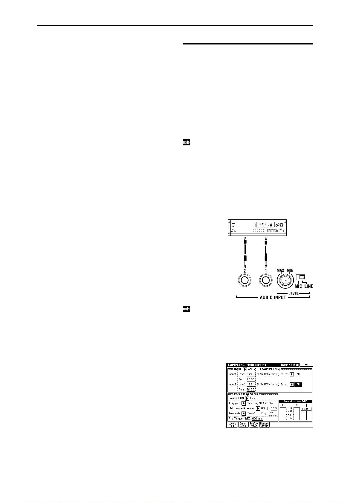
The converted program settings will automatically be
stored in the internal memory, but the sample data you
created will be lost when the power is turned off. In
order to reproduce the sound of the program after the
power is turned on again, you must first load the previously-saved sample data back into the TRITON STUDIO, using the Disk mode. When loading, it is best to
set “.KSC Allocation” to Clear.
When saving, it is a good idea to execute “Save All”
(☞PG p.166) to save the samples and multisamples
along with the converted program, and then load all of
this data together. (☞PG p.157, 162)
Sampling and looping a drum phrase
Here’s how you can sample a drum phrase (or similar
phrase) from an audio CD, and loop the playback.
You will need to provide a drum rhythm loop sample. Initially, it is a good idea to begin with a rhythm loop sample
that has a fairly simple beat.
As an example, we will sample one measure of a 140 BPM
drum phrase in a 4/4 time signature. In this example we
will use a CD player. For details on how you can digitally
sample or “rip” from the CDRW-1 option or from a SCSIconnected CD-ROM or CD-R/RW, refer to p.108.
This explanation assumes that you are starting from
the default state immediately after power-on.
1. Connect your external audio device and
adjust the input settings (Input)
1 Connect the AUDIO INPUT 1, 2 jacks on the rear
panel to the LINE OUT L and R jacks of your CD
player.
Set the AUDIO INPUT [MIC/LINE] switch to the
LINE position, and set the [LEVEL] knob near the
center.
R
AUX OUT
If the CDRW-1 option is installed, the analog audio
will be internally connected to the AUDIO INPUT 1
and 2 jacks.
Y ou can also “rip” digital audio data via the CDRW-1
option or a SCSI-connected CD-R/RW. (☞p.108)
2 Press the [SAMPLING] key to enter Sampling mode.
3 Press the Input Setup tab to select the P0: Recording,
Input/Setup page.
L
CD player
42
4 Set the various parameters so that the signal from the
AUDIO INPUT jacks will be input to the TRITON
STUDIO.
Page 51

Set the following parameters as shown.
Input 1: “Level” 127, “Pan” L000, “BUS” L/R
Input 2: “Level” 127, “Pan” R127, “BUS” L/R
When you change the Bus setting from Off to L/R or
IFX, the volume level of the AUDIO OUT L/MONO
and R jacks or the headphone volume may rise
abruptly. Please use caution.
2. Set the recording level
(Recording Level [dB])
1 Play back the audio source that you want to record.
If the display indicates “ADC OVERLOAD !!” (AD
converter input overload!), lower the level by turning
the rear panel [LEVEL] knob to an appropriate position. Alternatively, lower the level of the output source.
The best audio quality will be obtained at a level
slightly lower than when the “ADC OVERLOAD !!”
indication appears (i.e., the highest level that does not
cause an input overload).
2 Press the SAMPLING [REC] key.
The level meter allows you to check the volume of the
input.
If the display indicates “CLIP!!,” use the VALUE controller to lower the “Recording Level” slider (located
in the right of the display) from the +0.0 position to an
appropriate level.
3 When you have finished making adjustments, once
again press the SAMPLING [REC] key. Also stop the
playback of your audio source.
3. Specify the recording method (Recording)
1 Set “Source BUS” to L/R.
This setting lets you sample the sound of the L/R channels; i.e., the sound that is output from the headphones
and the AUDIO OUTPUT (MAIN) L/MONO and R
jacks.
2 Set “Trigger” to Sampling START SW.
With this setting, you can press the SAMPLING [REC]
key to enter record-ready mode, and then press the
SAMPLING [START/STOP] key to start recording.
4. Settings for the sample that will be
recorded (REC Sample Setup)
1 Press the Recording to access the P0: Recording,
Recording page.
2 Set “Save to” to RAM.
The recorded sample will be written into sample memory (RAM). (☞For details on the DISK setting, refer to
p.105)
3 Set “Sample Mode” to Stereo.
With this setting, the sound of the internal LR channels
can be sampled in stereo.
5. Record the sample
1 Press the SAMPLING [REC] key to enter record-
ready mode.
2 At the moment that you wish to start sampling, press
the SAMPLING [START/STOP] key.
Sampling will start.
It is a good idea to allow a bit of extra time before you
start and after you stop sampling.
3 At the moment that you wish to stop sampling, press
the SAMPLING [START/STOP] key.
Sampling will stop.
A 140 BPM drum phrase has now been sampled. The
sample will automatically be assigned to “Sample
(Sample select).”
Sampling will stop automatically if the remaining
amount of memory reaches zero.
4 Listen to the sampled sound, and assign a name to
the sample.
Y ou can play the “OrigKey” note to hear the sound that
was sampled.
After you have verified the sound, assign a name to the
sample (☞p.40) (e.g., LOOP1-140 BPM). Up to 14 characters can be input as the name of a stereo sample (the
two characters -L and -R at the end are fixed). When
you assign a name to either the L or R channel, the
other sample will be named automatically.
6. Make loop settings
Next we will delete unwanted portions from the sample,
and adjust the settings so that the sample will be looped
smoothly.
By default when the power is turned on, sampled
sounds will be looped automatically. (P0: Recording,
Preference page “Auto Loop On” On)
Quick Start
Power on/offDemo songPlaying
programs
Playing
combinations
Using
controllers
ArpeggiatorRPPRProgram
editing
editing
Combination
SamplingSong
43
Page 52

1 Press the [MENU] key to access the page menu, and
press P2: Loop Edit.
The P2: Loop Edit page will appear.
2 Notice that 0000: LOOP1-140BPM-L is selected for
“Sample (Sample Select),” and that the sample waveform data is displayed.
The selected sample is a stereo sample. The L and R
waveforms will be shown in the upper and lower parts
of the sample waveform display.
3 Use “Start” to set the start address, “LoopS (Loop
Start)” to set the loop start address, and “End” to set
the end address.
The sample will sound as follows.
When looping is on: S → E → LoopS → E → (continue
repeating LoopS → E)
When looping is off: S → E
Select “Start” (highlighted), and use the [VALUE] dial
etc. to specify the location at which the sample will
begin sounding. The vertical line in the display will
move accordingly.
If necessary, you can press the ZOOM buttons to
expand or shrink the waveform display. Zoom will
expand or contract the display beginning at the
“Start,” “LoopS (Loop Start),” or “End” point that is
selected.
Zoom-in vertically
Select the page menu command “Grid” to access the
dialog box.
Check “Grid,” set “Resolution” to , and press the OK
button.
Set “Grid” to 140. With these settings, vertical dotted
lines will be displayed at 140 BPM quarter note intervals.
Set “End.”
When “Loop” is On, the dotted vertical “Grid” lines
will start at “LoopS (Loop Start).” If you want to set
“End” at the end of one 4/4 measure, the fourth vertical line from the “LoopS (Loop Start)” line will be the
end of the first measure. Place “End” at this vertical
line.
Zoom-out horizontally
Maximum
horizontal zoom-out
Zoom-out vertically
Zoom-in horizontally
1x horizontal zoom-in
If you check “Use Zero,” locations where the waveform is at zero will automatically be found and
selected when you use the [VALUE] dial etc. to set
“Start,” “LoopS (Loop Start),” or “End” points. This
makes it easy to set these points to addresses that will
not produce clicks or noise in the loop.
For this example, set “LoopS (Loop Start)” and
“Start” to the same value.
If desired, you can make a dotted vertical line appear
in the sample waveform display to indicate the BPM.
If you use this function with waveforms that have a
specific BPM, it will be easier to make accurate settings for “End.”
4 Use “Truncate” to delete the unwanted data that is
outside of the start (or loop start) and end addresses.
Select the page menu command “Truncate” to access
the dialog box.
Select the Front & End radio button.
In this example, we will not change the settings of the
“Save to No.” and “Overwrite” check boxes, so press
the OK button to execute. When you execute the operation, the truncated samples 0002: LOOP1-140B0002-L
and 0003: LOOP1-140B0002-R will be automatically
assigned to Index 1.
Please refer to “A note on saving samples” (☞p.111)
for a cautionary note regarding the “Save to No.” and
“Overwrite” check boxes.
44
Page 53

Resampling an arpeggiated phrase in Program mode
You can play a program or combination, using the arpeggiator if desired, and resample your performance as audio
data (sound).
As an example, this section explains how to sample an
arpeggiated phrase in Program mode. Sampling can be
performed in the same way in Combination or Sequencer
modes as well.
The procedure here assumes that the TRITON STUDIO is in the default state immediately after turning
on the power.
1. Select the program that you want to resample
1 Press the [PROG] key to enter Program mode, and
select program INT-A028: Rezbo.
3. Specify the recording method
(Sampling Setup)
1 In the P0: Play, Sampling page, make the following
settings for Sampling Setup.
“Source BUS”: L/R
This lets you sample the sound of the L/R channel; i.e.,
the sound that is output from the headphones and the
AUDIO OUTPUT (MAIN) L/MONO and R jacks.
“Trigger”: Note On
With this setting, sampling will begin the instant you
play the keyboard.
“Save to”: RAM
The sample will be written into sample memory
(RAM).
“Mode”: Stereo
The sound will be sampled in stereo.
If desired, you can set “Sample Time” a bit longer
than necessary, and then after sampling, use editing
commands in Sampling mode (such as TRUNCATE)
to delete any unwanted portion at the beginning or
end of the sample.
If the tempo “” is 120 and the time signature is 4/4, it
will take two seconds to play one measure. If you
want to sample one measure, a sampling time of 00
min 02.000 sec will be the exact length.
Quick Start
Power on/offDemo songPlaying
programs
Playing
combinations
2 Turn the arpeggiator on (ARPEGGIATOR [ON/OFF]
key LED is lit), and play the keyboard to verify that a
phrase is produced.
Make sure that the arpeggio tempo “” is set to 120.
2. Adjust the recording level
(Recording Level [dB])
1 Press the Sampling tab to access the P0: Play, Sam-
pling page.
2 Press the SAMPLING [REC] key.
The level meter will indicate the volume of the phrase
to be sampled.
4. Make settings for the sample that will be
recorded
1 Select the page menu command “Select Bank & Smpl
No.” to access the dialog box.
2 Set “Bank,” “Sample No.(L),” and “(R)” to specify the
sample memory (RAM) and sample number into
which the sample will be written.
If the above “Mode” is Stereo, specify (L) and (R).
3 In the Convert to area, specify the number of the pro-
gram (into which the sample will be converted), the
multisample name, and the key assignment.
Check the check box and select one of the bank INT-E
initialized programs as the conversion-destination program number.
4 Press the OK button to finalize the settings.
Using
controllers
ArpeggiatorRPPRProgram
editing
editing
Combination
SamplingSong
Adjust the recording level as necessary, using the
“Recording Level” slider located at the right of the dis-
play.
The power-on default setting is –12 dB. With a setting
of –12 dB, CLIP will not be displayed even if the program is played at the maximum level.
3 When you have finished adjusting the level, press the
SAMPLING [REC] key.
Press the ARPEGGIATOR [ON/OFF] key to turn off
the arpeggiator.
5. Record the sample
1 Press the ARPEGGIATOR [ON/OFF] key to turn it
on.
Press the SAMPLING [REC] key.
Press the SAMPLING [START/STOP] key to enter
record-ready mode.
2 Play the keyboard. Recording will begin at the
instant you play a note.
All of the sounds you play from the keyboard and controllers will be recorded in the sample.
45
Page 54

3 Press the SAMPLING [START/STOP] key to stop
recording.
Sampling will end automatically when the specified
“Sample Time” is reached.
6. Listen to the sample and edit it
1 Press the Perf. Edit tab to select the P0: Play, Perfor-
mance Edit page, and select the program into which
the newly-recorded sample was converted.
INT-E: 101 was selected in the example shown here, so
press the [INT-E] key, then numeric keys [1], [0], and
the [1] key.
2 Play the C3 note on the keyboard to hear the sound
that was resampled.
REALTIME CONTROLS knobs 1–4, the Performance
Editor, and the various parameters in P1: Edit-Basic–
P9: Edit-Master Effect can be used to edit the program
for the sound you resampled, for example by adjusting the filter, EG, or effects. (☞p.34, 67)
If you want to adjust the loop point or other settings
of the sample, edit these parameters in Sampling
mode. (☞p.43)
Sample an arpeggiated drum
phrase together with an externally-input guitar
Here’s how you can resample an arpeggiated performance together with an external audio input source.
In this example, we will explain how a guitar connected to
the AUDIO INPUT jack can be played along to a drum
pattern played by the TRITON STUDIO, and how both
can be sampled together.
Sampling can be performed in a similar way in Combination and Sequencer modes as well as in Program
mode.
The procedure given here assumes that you are starting from the default state immediately after poweron.
1. Select the program that you want to sample
1 Press the [PROG] key to enter Program mode, and
select the INT-B020: Processed Kit program.
2 Turn on the arpeggiator (ARPEGGIATOR [ON/OFF]
key LED is lit), and play the keyboard to make sure
that a drum phrase is sounded.
Press the Arpeggio tab, and make sure that “Latch” is
checked.
Also adjust the arpeggiator tempo “” as desired.
3 Press the ARPEGGIATOR [ON/OFF] key to turn off
the arpeggiator.
2. Connect your guitar and make input settings
1 Connect your guitar to the rear panel AUDIO INPUT
1 jack.
Set the AUDIO INPUT [MIC/LINE] switch to the LINE
position, and set the [LEVEL] knob to approximately
the center position.
Guitar
If you are using a guitar with passive pickups (i.e.,
without an internal pre-amp), the mismatch of
impedance levels will make it difficult to sample at an
appropriate level. You should route the signal from
the guitar through a pre-amp or effect unit.
46
Page 55

2 Press the Sampling tab to access the Sampling page.
3 Set the parameters so that the signal from the AUDIO
INPUT 1 jack will be sent to the L channel.
Make the following settings.
“Input”: Analog
Input 1 “Level”: 127, “Pan”: as desired, “BUS Select”:
L/R
3. Set the recording level
(Recording Level [dB])
1 Play your guitar at the volume that you will be
recording.
If the display indicates “ADC OVERLOAD !!” (AD
converter input overload), turn the rear panel [LEVEL]
knob toward MIN to adjust the level appropriately.
The best audio quality will be obtained at the highest
possible level that does not cause an overload; i.e., a
level that is slightly below the point where “ADC
OVERLOAD !!” is displayed.
2 Press the SAMPLING [REC] key.
Play your guitar, and the level meter will indicate the
volume at which the guitar will be sampled.
Press the ARPEGGIATOR [ON/OFF] key to turn it on,
play the keyboard to start the arpeggio, and play your
guitar while adjusting the final volume.
Adjust the recording level as necessary, using the
“Recording Level” slider located at the right of the dis-
play.
The power-on default is –12 dB. With a setting of –12
dB, CLIP will not be displayed even if the program
drum pattern and the guitar are played at the maximum level.
If the balance between instruments is not to your liking, use the [LEVEL] knob or the performance editor
“Amp Level” to adjust the balance.
3 When you have finished making adjustments, press
the SAMPLING [REC] key.
Press the ARPEGGIATOR [ON/OFF] key to turn off
the arpeggiator.
4. Specify the recording method
(Sampling Setup)
1 In the Sampling page, set the following Sampling
Setup parameters.
“Source BUS”: L/R
“Trigger”: Sampling START SW
“Metronome Precount”: 4
“Save to”: RAM
“Mode”: Stereo
“Sample Time”: as desired
With these settings, if you press the SAMPLING [REC]
key to enter recording-standby mode and then press
the SAMPLING [START/STOP] key, recording will
begin after a four-beat count.
5. Specify the sample that will be recorded
Make settings as described in “4. Make settings for the
sample that will be recorded” (☞p.45).
If you omit making settings at this point and simply continue with the settings of p.45, the sample will be assigned
to the next higher key of the same program number.
6. Record the sample
1 Press the ARPEGGIATOR [ON/OFF] key to turn it
on.
2 Press the SAMPLING [REC] key to enter record-
ready mode.
When you press the SAMPLING [STAR T/STOP] key, a
count-down will begin. Play the keyboard during the
count-down.
After a four-beat count-down, recording will start.
Play your guitar. The arpeggiator will also start after
the count-down.
3 Press the SAMPLING [START/STOP] key to stop
recording.
Sampling will also end automatically when the specified “Sample Time” is reached.
4 Press the ARPEGGIATOR [ON/OFF] key to turn it
off.
7. Listen to the sample
Now you can listen to the sample that was recorded. (“6.
Listen to the sample and edit it” ☞p.46)
Quick Start
Power on/offDemo songPlaying
programs
Playing
combinations
Using
controllers
ArpeggiatorRPPRProgram
editing
editing
Combination
SamplingSong
47
Page 56

Examples of sampling settings
Resampling only the sound of the TRITON STUDIO
(e.g., arpeggiator and/or keyboard performance)
“Input”: Analog
Input1 “BUS Select”: Off
Input2 “BUS Select”: Off
“Source BUS”: L/R
“Recording Level”: –12.0
“Auto +12dB On”: On (chacked) ☞PG p.5, 57
Resampling the sound of the TRITON STUDIO
(arpeggiator and/or keyboard performance) together
with the input sound from the AUDIO INPUT 1 jack
“Input”: Analog
Input1 “BUS Select”: L/R, “Pan”: C064 or as desired
Input2 “BUS Select”: Off
“Source BUS”: L/R
“Recording Level”: –12.0
“Auto +12dB On”: On (chacked) ☞PG p.5, 57
Sampling only the stereo input sound from the
AUDIO INPUT 1 and 2 jacks while you listen to the
sound of the TRITON STUDIO (arpeggiator etc.)
“Input”: Analog
Input1 “BUS Select”: 1/2, “Pan”: L000
Input2 “BUS Select”: 1/2, “Pan”: R127
“Source BUS”: Indiv.1/2
“Recording Level”: 0.0
“Auto +12dB On”: Off (unchacked) ☞PG p.5, 57
In this case, the sound that is input to AUDIO INPUT 1
and 2 will be output only to AUDIO OUTPUT (INDIVIDUAL) 1 and 2.
Using the metronome
It is convenient to use the metronome when you want to
play a program or combination at a specific tempo and
sample your performance.
To access the metronome settings, use the Program or
Combination P0: Play, Sampling page menu command
“Metronome Setup.” We recommend that you set “BUS
(OUTPUT) Select” to either 3 or 4, and connect the (INDIVIDUAL) 3 or 4 jack to your mixer so that the metronome
can be monitored via your mixer.
48
Page 57

Producing a song
This section explains how to use the TRITON STUDIO’s
internal sequencer. The example procedures described
here will cover realtime recording and step recording, as
well as various convenient functions provided by the
internal sequencer, such as template songs, preset patterns, and the arpeggiator.
There are many other recording methods and functions
(☞p.80), but working through this section will give you a
basic understanding of the song production process.
This explanation assumes that you are starting from
the default state immediately after power-on.
Creating the basic song
1. Loading a template song, and copying
preset patterns (drum phrases)
1 Press the [SEQ] key to enter Sequencer mode.
Check the “Copy Pattern to Track too?” check box.
If this is checked, a drum pattern will be copied to the
song after the template song is loaded.
Press the OK button to load the template song.
A dialog box will appear.
Make sure that Preset, P109: AcidJazz 1/Std2 is
selected at the right of “Pattern.” If not, use the
VALUE controller to select it.
Y ou can pr ess the SEQUENCER [START/STOP] key to
hear the selected pattern. To stop, press the [START/
STOP] key once again.
Press the OK button to copy the pattern.
The “Measure” value will change from 001 to 009. This
indicates that the pattern has been copied from measure 1 to measure 8, and that the next time you press
the OK button, the pattern will be copied from measure
9.
Quick Start
Power on/offDemo songPlaying
programs
Playing
combinations
Using
controllers
ArpeggiatorRPPRProgram
2 Load a template song.
Press the page menu button to access the page menu,
and press “Load Template Song.”
A dialog box will appear.
Press the popup button located at the right of “From,”
and select P13: Acid Jazz from the menu.
There are 16 template songs, each containing program, pan, volume, and effect settings suitable for
various styles of music. By loading a template into a
song, you can begin recording immediately without
having to make the same frequently-used settings
each time.
If you want to specify the program and volume settings yourself from scratch, refer to “Preparations for
recording” (☞p.82).
Press the Exit button.
In the Sequencer P0: Play/REC, Program T01–08 page,
the “Song Select” field will indicate S000: Acid Jazz.
Track Select
Preset patterns can be used in a song at any time. This
can be done by using the page menu commands “Put
To Track” or “Copy To Track” (Sequencer P6: Pattern/RPPR, Pattern Edit page) (☞PG p.77).
editing
editing
Combination
SamplingSong
49
Page 58

3 When you play the keyboard, you will hear the drum
program for track 1 of the template song.
4 Press the popup button located at the left of “Track
Select,” and select Track 02: Bass. When you play the
keyboard, you will hear a bass sound.
“Track Select” is the track that will be used to record/
play song data. Normally, the track selected here can
be played from the keyboard, and during recording,
your performance will be recorded on this track (in
cases other than Multi REC or Master Track).
Next select T03–T08 in order, and play them from the
keyboard. (The TRITON STUDIO has sixteen sequence
tracks, but this template song specifies only tracks 1–8.)
Select Track03: Elec. Piano.
5 Press the SEQUENCER [START/STOP] key to play
back the preset pattern that you copied. Play the keyboard while you listen to the drum pattern.
6 Press the SEQUENCER [START/STOP] key to stop.
2. Repeatedly playing specific measures of
a track (Track Play Loop)
Here’s how to use Track Play Loop to repeatedly play
back a drum phrase.
1 Press the PlyLoop tab to access the P0: Play/REC,
PlayLoop T01–08 page.
2 Check track 1 “Track Play Loop,” leave “Loop Start
Measure” as it is, and set “Loop End Measure” to 008.
3 When you press the SEQUENCER [START/STOP]
key, the drum phrase will be played back repeatedly.
When the playback has repeated for the number of
measures in the song as specified by “Length” (the
power-on default is 64 measures), it will stop automatically.
By using “Play Intro” you can begin the loop after
adding an introduction (☞PG p.55).
Track Play Loop will continue repeating for the number of measures specified by “Length.” If you want to
limit the number of repetitions or place other performance data (e.g., a drum fill-in) in that track, you will
need to expand the pattern into actual performance
data. Use the page menu command “Repeat Mea-
sure” P5: Edit, Track Edit page to specify the number
of playback repetitions and expand the pattern as
playback data. In the sample illustration below, performance data will be created to play measures 1–8 of
track 1 for four times (i.e., 32 measures).
3. Recording the bass track
1 If playback is occurring, press the SEQUENCER
[START/STOP] key to stop playback.
Press the [LOCATE] key to return to the beginning of
the song.
The location will indicate 001:01.000.
2 Press the [EXIT] key, and then press the Prog. 1–8 tab
to access the P0: Play/REC, Program T01–08 page.
3 Use “T rack Select” to select the track that you want to
record.
In this example, select Track02: Bass.
Press the SEQUENCER [START/STOP] key to start
playback, and practice playing the phrase that you
want to record.
When you are finished rehearsing, press the
SEQUENCER [START/STOP] key to stop playback.
Press the [LOCATE] key.
When the power is turned on, the Recording Setup of
the TRITON STUDIO will be set to Over Write
recording, in which newly recorded data will be
overwritten. For details on other recording modes,
refer to p.83 and PG p.57.
When recording rapid or difficult phrases, you can
slow down the tempo and record at a more comfortable tempo. Simply adjust the “ (Tempo).” After
recording, restore the original tempo.
50
Page 59

You can use the Quantize and Resolution functions
to correct the timing of your performance as it is
recorded.
For example during realtime recording, suppose that
you input eighth notes at slightly inaccurate timing,
as shown in line 1 of the diagram below. If you set
“Reso” (Resolution) to and performed realtime
recording, the timing would automatically be corrected as shown in line 2. With a setting of Hi, the
performance will be recorded with the exact timing at
which it was played.
Independent of this function, there is also a page menu
command “Quantize” (P5: Track Edit, Track Edit page)
that can be used to correct the timing of performance
data that has already been recorded. If data (recorded
without using Realtime Quantize) falls at the timings
shown in the above figure 1, then when played back, it
will be corrected to the timings shown in figure 2 if you
set “Quantize” to a “Resolution” of and press the
OK button.
4 Press the SEQUENCER [REC/WRITE] key.
You will hear the metronome. The TRITON STUDIO
will be in record-ready mode. (☞Refer to PG p.58 for
details on metronome settings.)
5 Press the SEQUENCER [START/STOP] key.
After a two-measure count, recording will begin.
Play the keyboard for about 16 measures, and record
your performance.
If you make a mistake or decide to re-record, press the
[START/STOP] key to stop recording, and press the
[COMPARE] key.
When you press the [COMPARE] key to execute the
Compare function, you will return to the state prior to
recording. (☞Refer to p.97 for the content that can be
compared in Sequencer mode.)
6 When you are satisfied with your performance, press
the SEQUENCER [START/STOP] key to stop recording.
For example if your performance in measures 5–8
was the best take, you can use the Track Play Loop
function to repeatedly play back just this portion.
In the P0: Play/REC, PlayLoop T01–08 page, check
“Track Play Loop” for track 2, set “Loop Start Mea-
sure” to 005, and set “Loop End Measure” to 008.
When you press the SEQUENCER [START/STOP]
key, repeated playback will begin.
After you press the SEQUENCER [START/STOP]
key to stop playback, we recommend that you press
the [LOCATE] key to return to the beginning of the
song. After recording, you will automatically return
to the measure at which recording began.
4. Recording arpeggio patterns
The performance of an arpeggio pattern can be recorded
into a song. With the settings of this template song, the
arpeggiator will function on track 4.
1 In “Track Select,” choose Track04: Guitar.
2 Press the ARPEGGIATOR [ON/OFF] key.
3 Press the SEQUENCER [START/STOP] key and play
single notes or chords.
Verify that arpeggios are sounded in synchronization
with the tempo of the drum and bass performance, and
rehearse your performance.
4 Press the SEQUENCER [START/STOP] key to stop
playback.
Then press the [LOCATE] key to move the location to
the beginning of the song.
5 Start recording.
Press the SEQUENCER [REC/WRITE] key, and then
press the SEQUENCER [START/STOP] key.
If you play notes on the keyboard during the count-in,
the arpeggio will begin at the same time that recording
begins, and then that pattern will be recorded.
Play the keyboard for about 16 measures and record
your performance.
Press the SEQUENCER [START/STOP] key to stop
recording.
If you made a mistake or would like to re-record, you
can use the Compare function (press the [COMPARE]
key) to re-record as many times as you wish.
The note data that was generated by the arpeggio
pattern will be recorded. If you change the ARPEG-
GIATOR [GATE] or ARPEGGIATOR [VELOCITY]
knob settings while recording an arpeggio pattern,
this data will also be recorded, but it will not be possible to add changes by overdubbing [GATE] or
[VELOCITY] data afterward for those notes.
Quick Start
Power on/offDemo songPlaying
programs
Playing
combinations
Using
controllers
ArpeggiatorRPPRProgram
editing
editing
Combination
SamplingSong
51
Page 60

5. Recording other tracks
1 As described in “Recording the bass track,” use
“Track Select” to select Track03: Elec. Piano, and
record about 16 measures.
6. Step recording
The TRITON STUDIO provides two main methods of
recording a song. The first is realtime recording, in which
your performance on the keyboard and operation of the
joystick and other controllers are recorded in realtime.
This is how we recorded the bass and electric piano tracks
in the preceding sections.
The second method is step recording, in which you can
specify the timing, note length, and velocity of each note.
in the LCD screen, and use the keyboard to input the pitch
of the note. Only the note-on/off data is recorded. Step
recording is suitable when you want to create a distinctive
mechanical feel, or when you want to record phrases that
would be impossible or too rapid to play “live.”
Rapid phrases can also be recorded in realtime by
temporarily slowing down the sequencer tempo.
Here’s the procedure for step recording.
1 Press the [MENU] key to access the Jump menu, and
press P5: Track Edit.
The P5: Track Edit, Track Edit page will appear.
2 Set “Track Select” to Track 08: Lead Synth.
For this example we will input a lead performance
using an analog synthesizer sound.
3 Set “From Measure” to 001.
With this setting, step recording will begin from measure 1.
4 Press the page menu button to access the page menu,
and press “Step Recording.”
A dialog box will appear.
5 Set “Step Time” to specify the basic timing value at
which you will input notes and rests.
In the popup menu at left, you can specify a value in
the range of (whole note)– (32nd note). For this
example, select (16th note).
If you want to input triplets or dotted notes, use the
popup menu at the right to select “3” for triplets, or “.”
for dotted notes. Select “–” if you want to use the
unmodified length of the note that is selected at the
left.
“Note Duration” indicates the length that the note
itself will sound. Smaller values will produce a staccato
note, and larger values will produce a legato note. For
this example, leave this setting unchanged.
“Note Velocity” is the velocity (playing strength), and
larger values will produce a louder volume. Set this to
about 090.
If you select Key for this parameter, the velocity with
which you actually play the keyboard will be input.
6 On the keyboard, press and then release the first note
that you want to input.
The data you input will appear in the LCD screen as
numerical values. In the upper right, M001 01.000 will
change to M001 01.048. The next note you input will be
placed at this location.
Continue pressing notes to input a melody.
You can also delete notes or rests, or input rests or ties.
• To delete a note or rest that you input, press the Step
Back button. The previously-input note will be
deleted.
• To input a rest, press the Rest button. This will input a
rest of the “Step Time” value.
• To modify the length of a note, you can modify the
“Step time” value before you input the note. However
if you want to extend the length (tie) of the note,
press the Tie button. At this time, the previously-input
note will be extended by the length of “Step time.”
If you want to check the note that you will input
next, press the [PAUSE] key. In this state, playing a
key will produce sound, but will not input a note.
Press the [PAUSE] key once again to cancel the
record-pause state, and resume input.
To input a chord, simultaneously press the notes of
the desired chord. Even if you do not press them
simultaneously, notes that were pressed before you
took your hand off of all keys will be input at the
same location.
However in the above example, the program of track
8 will not sound chords. This is because the program
is set to mono mode, and the song follows the setting
of the program.
7 When you are finished inputting, press the Done but-
ton.
8 Press the SEQUENCER [START/STOP] key to play
back.
52
Page 61

When you begin step recording, all data that follows
the measure where you began recording will be
erased from that track.
You need to be aware of this if you begin step recording from a measure mid-way through the song.
If you want to re-input data into a measure that
already contains data, perform step recording in
another un-recorded track, and execute “Move Measure” or “Copy Measure” (☞PG p.72).
If you want to edit or add to the recorded data, you
can use the “Event Edit” function (☞PG p.69).
7. Using controllers to record tonal changes
Let’s try using the realtime controllers and the joystick to
add effects to the performance that we just step-recorded
on track 8.
1 Press the [EXIT] key, and then press the Preference
button to move to the P0: Play/REC, Preference page.
2 Set the “Recording Mode” to Over Dub.
Over Dub allows you to add to a previously-recorded
track.
3 For “Track Select,” make sure that Track08: Lead
Synth is selected.
Press the SEQUENCER [START/STOP] key to start
playback, and operate the realtime controllers and joystick to rehearse. When you are finished rehearsing,
press the SEQUENCER [START/STOP] key to stop.
Press the [LOCATE] key.
4 Start recording.
Press the SEQUENCER [REC/WRITE] key, and then
press the SEQUENCER [START/STOP] key.
After a two-measure count-in, recording will begin.
Operate the LFO CUTOFF or RESONANCE/HPF real-
time controllers or the joystick (±Y axis) to record their
movements.
When you are finished performing, press the
SEQUENCER [START/STOP] key.
If you make a mistake or want to re-record, press the
[COMPARE] key to execute the Compare function,
and then re-record.
Recording the drum part
In this explanation, we used the TRITON STUDIO’s builtin patterns to create the drum part, but if you want to
input the drum part yourself, it will be convenient to set
“Recording Mode” to Over Dub for recording. (☞p.84)
It is best to use realtime recording (“3. Recording the bass
track” ☞p.50) to record the rhythm instruments in the
order of bass drum, snare, and hi-hat.
Naming the song and tracks
It’s a good idea to assign a name to each song and track so
that they can be easily identified.
Naming a song
1 Press the [EXIT] key to access P0: Play/REC.
The “Rename Song” page menu command can also be
selected from P2, P3, P4, or P7, as well as from P0.
2 Press the page menu button to access the page menu,
and press “Rename Song.”
3 A dialog box will appear. Press the text edit button
and input the desired song name.
For the procedure of inputting a name, refer to p.40, 56.
4 When you are finished inputting the name, press the
OK button twice to finish the procedure. (☞p.40)
Naming a track
1 Press the [MENU] key to select P5: Track Edit, and
press the Track Name tab.
The P5: Track Edit, Track Name page will appear.
2 Press the text edit button for the track whose name
you want to edit, and input the desired name for that
track.
For the procedure of inputting a name, refer to p.40, 56.
3 When you are finished inputting the name(s), press
the OK button.
You can also assign a name to each cue list and user
pattern.
Quick Start
Power on/offDemo songPlaying
programs
Playing
combinations
Using
controllers
ArpeggiatorRPPRProgram
editing
editing
Combination
SamplingSong
53
Page 62

Saving the song
Remember to save the song you created.
Begining on page 88 is a description of how you can
perform further editing on the song you created here
in “Quick Start” and how you can assign it to a cue
list, so we recommend that you save the song you created here for further use.
On the TRITON STUDIO, this data will be lost when
the power is turned off.
1 Perform steps 1–4 of “Saving sample data” (☞p.41).
2 Press the page menu button to access the page menu,
and press “Save SEQ.”
The Save Songs and Cue Lists Data dialog box will
appear.
3 When the dialog box appears, press the text edit but-
ton to access the text dialog box, input a name for
your song.
Assign a filename of SEQ_DM1 to the song you created
in this “Quick Start” section, and press the OK button.
4 Press the OK button to save the data.
If you have assigned the name described above, a file
named SEQ_DM1.SNG will be created.
54
Page 63

Basic functions
Saving data
Types of data that can be saved
On the TRITON STUDIO, there are three ways to save
data: writing to internal memory, saving on media
(floppy disk, internal hard drive, CD-R/RW, hard disk
and other removable media etc.), and MIDI data dump.
Writing to internal memory
The following types of edited can be written into the internal memory.
• Program
Programs 0–127 in banks INT-A–INT-F, EXB-A–EXB-G
(However, bank INT-F is available only if the EXBMOSS option is installed.)
• Combination
Combinations 0–127 in banks INT-A–INT-E, EXB-A–
EXB-G
• Global settings
(Global P0: Basic Setup–P4: Category Name)
• User drum kits 00 (I-A/B)–143 (User)
• User arpeggio patterns U000 (I-A/B)–U506 (User)
• User template songs U00–U15
Song settings such as the song name and tempo, track
settings (☞p.81), arpeggiator settings, and effect settings can be saved (written) to internal memory. However, the musical data for song tracks and patterns are
not saved to internal memory. Furthermore, settings
that govern how the musical data is played back such
as “Meter,” “Metronome,” “Play/Mute,” “Track Play
Loop (including Start/End measure),” and RPPR settings will not be saved either. Use the Sequencer mode
page menu command “Save Template Song” to write
this data (☞PG p.54).
If multisamples or samples from the RAM bank are
used in the Multisample or Drum Kit of a program,
you should be aware that these multisamples or samples cannot be written into memory. This means that
if you turn the power of and then on once again, programs or combinations that use such multisamples or
samples will not sound as intended. To reproduce
such programs or combinations, the necessary multisamples or samples must be saved on media (such as
floppy disk, hard disk, CD-R/RW and removable
disk etc.), and then reloaded.
Data that you edit in Sequencer, Song Play, or Sampling cannot be saved in internal memory by the
Write operation.
Saving to various types of media
The following data can be saved to various types of
media.
• .PCG file:
Programs, combinations, global settings, user drum
kits, user arpeggio patterns (The data that was checked
in the check boxes of the Save dialog box will be
saved.)
• .SNG file: Song and cue list data
• .KSC, .KMP, .KSF files:
Lists of sample and multisamples (.KSC file), multisamples (.KMP file), samples (.KSF file).
• .MID file:
Saves a Sequencer mode song in Standard MIDI File
(SMF) format.
• .EXL file:
System exclusive data from an external device that was
saved on the TRITON STUDIO (This allows the TRITON STUDIO to be used as a data filer.)
• .JKB file:
Jukebox lists are saved in Song Play mode (☞p.122).
All other types of file are saved in Disk mode.
• .WAV and .AIF files:
A sample you recorded can be exported (written) as a
WAVE file or AIFF file.
• .KCD file:
Audio track list
MIDI data dump
The following types of data can be transmitted as a MIDI
data dump and saved on an external data filer or other
device.
• Programs, combinations, global settings, user drum
kits, and user arpeggio patterns
• Songs, cue lists
Basic functions
Saving dataLoading dataProgram
settings
settings
Combination
songs
Producing
settings
Sampling
CD
Creating a
SMF
playback
System
settings
settings
Drum kit
settings
Arpeggiator
55
Effects
settings
Other
functions
Page 64

About preloaded data and preset data
“Preloaded data” refers to the data that is loaded in the
TRITON STUDIO when it is shipped from the factory . You
are free to rewrite this data, and with the exception of the
demo songs, the data will be written to the location listed
in “Writing to internal memory.” This data is also stored
in the internal hard disk and on the included floppy disk
(except for the demo songs).
• Program banks INT-A–INT-D: 000–127
• Combination banks INT-A–INT-D: 000–127
• User drum kits 000 (I-A/B)–015 (I-A/B), 128 (User)–
131 (User)
• User arpeggio patterns U000 (I-A/B)–199 (I-A/B),
U312 (User)–U478 (User)
• Demo songs S000–S006
Preset data is data that cannot be rewritten by the Write
operation. This includes the following data.
• Program banks G, g(1)–g(9), g(d): 001–128
• Preset drum kits 144 (GM)–152 (GM)
• Preset arpeggio patterns P000-P004
• Preset template songs P00–P15
• Preset patterns P000–P149
Writing to internal memory
Writing a program or combination
The programs or combinations that you create by using
the Performance Editor or by editing parameters in the
various Edit pages can be saved in the internal memory of
the TRITON STUDIO. This action is referred to as “writing a program” or “writing a combination.” If you want
your edited data to be preserved after the power is turned
off, you must write it.
There are two ways to write a program or combination.
Before you write data into memory , you must turn off
the memory protect setting in Global mode.
(☞“Memory protect”)
A combination does not contain the actual program
data for each timbre, but simply remembers the number of the program used by each timbre. If you edit a
program that is used by a combination, or exchange it
with a different program number, the sound of the
combination will also change.
Using a page menu command to write
1 Select the page menu command “Write Program” or
“Write Combination.”
The Write Pr ogram/W rite Combination dialog box will
appear.
You can also access the same dialog box by holding
down the [ENTER] key and pressing the [0] key.
The screen shown is for Program mode
56
2 Check the program/combination name displayed in
the upper line (the writing source).
3 If you wish to change the name of the program/com-
bination, press the text edit button.
The text dialog box will appear. Input the name of the
program/combination. ☞“Assigning a name
(Rename)”
After you have input the name, press the OK button
to return to the Write Program/Write Combination
dialog box.
4 In “Category,” specify the category of the program/
combination.
In the case of a program, the category you specify here
will be used when you select a program by category in
Program P0: Play “Category” (Category/Program
Select). Program categories can also be used when
selecting programs in Combination P0: Play, in P1:
Edit-Program/Mixer “Category” (Category/Timbre
Program Select), or in Sequencer P0: Play/REC “Category” (Category/Track Program Select).
Page 65

In the case of a combination, the category you specify
here will be used when you select a combination by
category in Combination P0: Play “Category” (Category/Combination Select).
5 Use “To” to specify the bank and number of the writ-
ing destination program/combination.
Use the VALUE controllers or the BANK keys to make
your selection.
6 To execute the Write operation, press the OK button.
To cancel without executing press the Cancel button.
When you press the OK button, the display will ask
“Are you sure?” When you press the OK button once
again, the data will be written.
Using the (SEQUENCER) [REC/WRITE] key to
write
This method can only be used to re-write (update) the
selected program/combination number.
1 Press the SEQUENCER [REC/WRITE] key.
The following Update Program/Update Combination
dialog box will appear.
The screen shown is for Program mode
File Disk Save: Sav e All...Sa v e Audio CD Track List,
mLAN Nick
Name
Utility page menu command: Rename
Global P0: Nick Name (if the EXB-mLAN is
installed)
Press the text edit button to access the text edit dialog
box.
For an example of how to input a name, refer to p.40.
Text
Cursor buttons
Move the cursor
to left or right.
Cursor
Clear button
Delete all characters
of the text.
Space button
Insert a space at the cursor
location.
Character Set
Selects the type of
character.
Character buttons
Shift button
Switches
between
uppercase and
lowercase
Delete button
Deletes the character
to the left of the
cursor.
Cancel button, OK button
If you are satisfied with the text
that you input, press the OK
button. If you wish to discard
your input and exit the text edit
box, press the Cancel button.
Basic functions
Saving dataLoading dataProgram
2 To write the data, press the OK button. To cancel
without writing, press the Cancel button.
Assigning a name (Rename)
You can modify the name of an edited program, combination, song, drum kit, user arpeggio pattern, multisample
or sample etc..
Y ou can also modify the category names for programs and
combinations.
These renaming operations can be performed in the following pages.
Progaram Program P0...9 page menu command: Write
Combination Combination P0...9 page menu command:
Song Sequencer P0, 2...4, 7 page menu command:
Cue List Sequencer P1 page menu command: Rename
Track Sequencer P5: Track Name
Pattern Sequencer P6: Pattern Name
Multisample Sampling P0...4 page menu command:
Sample Sampling P0...4 page menu command:
Drum Kit Global P5 page menu command: Rename
User arpeggio
pattern
Program category
Combination
category
Progaram
Write Combination
Rename Song
Cue List
Rename MS
Rename Sample
Drum Kit
Global P6 page menu command: Rename
Arpeggio Pattern
Global P4: Program Cat.
Global P4: Combination Cat.
Memory protect
To prevent programs, combinations, songs, user drum
kits, and user arpeggio patterns from being overwritten
accidentally, the TRITON STUDIO provides a Memory
Protect setting that prohibits writing to memory.
Before you save edited data or load data from floppy disk,
hard disk or other external media, use the following procedure to turn the memory protect off (uncheck the appropriate check box).
You must also turn memory protect off before loading the
above data from media or via a MIDI data dump, or
before recording in Sequencer mode.
1 Press the [GLOBAL] key to enter Global mode.
2 After pressing the [MENU] key, press either P0: Basic
Setup or the [0] key.
3 Press the System Pref. tab.
The System Preference page will appear.
4 Press the “Memory Protect” check box for the type of
data you wish to write to internal memory, so that the
box is unchecked. When the box is unchecked, Memory Protect is off, and data of this type may be written
to internal memory.
settings
settings
Combination
songs
Producing
settings
Sampling
CD
Creating a
SMF
playback
System
settings
settings
Drum kit
settings
Arpeggiator
Effects
settings
Other
functions
57
Page 66

About the Edit Buffer
When you select a program or combination in Program
P0: Play and Combination P0: Play , the pr ogram or combination data is called into the “edit buffer.”
When you modify the parameters in P0: Play or in the Edit
pages P1–P9 of Program mode or Combination mode, the
changes you make will affect the data in the edit buffer.
If you wish to save this modified data into internal memory, you must perform the Write operation.
When you perform the Write operation, the data in the
edit buffer is written to the specified program number or
combination number of the specified bank.
If you select another program or combination without
writing, the data of the newly selected program or combination will be called into the edit buffer, and your changes
will be lost.
When you press the [COMPARE] key in Program
mode or Combination mode, the data from memory
(i.e., the contents that were written into memory) will
be temporarily called into the edit buffer. This allows
you to compare the settings you are editing with the
original un-edited settings.
Editing applies to the data in the edit
buffer. Programs or combinations will
play according to the data in the edit
When you write, the program or
combination settings will be
saved in internal memory.
Program
Bank INT-A 0...127
Bank EXB-A 0...127
Edit Buffer
Write
Internal Memory
Program
buffer.
Select
Combination
Bank INT-A 0...127
Edit
When you select a program or
combination, its data is called from
internal memory into the edit
buffer.
Combination
Bank EXB-A 0...127
Writing global settings, user drum kits, and user arpeggio patterns
The settings you edit in Global mode can be written into
internal memory. This is done using the operations Write
Global Setting, Write User Drum Kits, and Write User
Arpeggio Patterns. If you wish to use these edited set-
tings after you turn the power off, be sure to write the
data first.
There are two ways to write global settings, user drum
kits, and user arpeggio patterns.
Before you write a user drum kit or user arpeggio
pattern, the Global mode memory protect setting
must be turned off (☞“Memory protect”).
The user arpeggio pattern parameter settings
“Tempo,” “Pattern,” “Octave,” “Resolution,” “Sort,”
“Latch,” “Key Sync,” and “Keyboard” are set independently in the Program, Combination, and Song
modes. These settings are not saved when you perform the Write operation described here.
If you have edited these parameters in Program or
Combination mode you must return to that mode to
write them.
Using a page menu command to write
1 To write global settings (the various settings in Glo-
bal P0–P4), press the page menu command “Write
Global Setting” in Global P0–P4.
The Write Global Setting dialog box will appear.
To write user drum kits, press the page menu command “Write Drum Kits” in Global P5.
The Write Drum Kits dialog box will appear.
To write user arpeggio patterns, press the page menu
command “Write Arpeggio Patterns” in Global P6.
The Write Arpeggio Patterns dialog box will appear.
The same dialog box will also appear if, in each of the
above pages, you hold down the [ENTER] key and
press the [0] key.
2 To execute the Write operation, press the OK button.
To cancel, press the Cancel button.
When you press the OK button, the display will ask
“Are you sure?” Press the OK button once again to
write the data.
58
Page 67

Using the (SEQUENCER) [REC/WRITE] key to
write
1 In the following pages, press the SEQUENCER [REC/
WRITE] key.
A dialog box will appear.
Global settings: Global P0–P4
User drum kits: Global P5
User arpeggio patterns: Global P6
The example shown is for Update Arpeggio Patterns
2 To execute the Write operation, press the OK button.
To cancel, press the Cancel button.
Saving on media
For details on the data that can be saved on storage media.
(“Types of data that can be saved” ☞p.55).
Song data and cue lists in the TRITON STUDIO’s
Sequencer mode, as well as multisamples and samples cannot be written into internal memory. This
data will disappear when the power is turned off. If
you want to keep this data, you must save it on a
floppy disk, the internal hard drive, the CDRW-1
option, or an externally-connected SCSI CD-R/RW or
other storage device (hard disk, removable disk etc.).
Other types of data can also be saved on storage
media. Even if you later modify this data, you will
always be able to reload the original settings. It is a
good idea to save your settings whenever you have
created something that you like.
Basic functions
Memory in Global mode
When the power is turned on, the Global mode data is
called from internal memory into the Global mode memory area. Then when you modify the parameters in Global
mode, the data in the memory area will be modified. If
you wish to save this modified data in internal memory,
you must Write it.
When you write, the data in the memory area will be written into the global settings, drum kits, and arpeggio patterns of internal memory.
If you turn off the power without writing, the modified
data in the memory area will be lost.
Editing will affect the data that has
When you Write, the various
Global mode settings will be
saved in internal memory.
Global Setting
been called into the memory area.
Memory Area
Write
Power On
Internal Memory
Drum Kit
Edit
When the power is turned
on, the settings are called
into the memory area.
Arpeggio
Pattern
Types of media that can be used
Floppy disks
You can use MS-DOS format 3.5 inch 2HD and 2DD
floppy disks. The formatted capacity of a floppy disk is
1.44 MB for a 2HD disk (18 sectors/track), and 720 KB for
a 2DD disk (9 sectors/track).
Internal hard drive
This supports MS-DOS format FAT16 and FAT32.
CDRW-1 option (CD-R/RW)
This supports UDF format. UDF format CD-R/RW discs
can be written or read. (Packet writing is supported ☞PG
p.299).
You can also record/play CD-DA (audio CD), and load
ISO 9660 (level 1) format data.
External SCSI storage media
Data can be stored on external SCSI storage media such as
a hard disk, MO, Zip, JAZ, or ORB disk.
For details on CD-R/RW, refer to the above “CDRW-1
option (CD-R/RW).”
When you insert media for the first time after turning
on the power, or when you exchange disks, touch the
LCD screen. so that the TRITON STUDIO will detect
the media. When the media has been detected, the
LCD screen will display information for that media.
If two or more media are detected, use “Drive select”
to switch between media.
Saving dataLoading dataProgram
settings
settings
Combination
songs
Producing
settings
Sampling
CD
Creating a
SMF
playback
System
settings
settings
Drum kit
59
settings
Arpeggiator
Effects
settings
Other
functions
Page 68

Formatting media
You can format a floppy disk, the internal hard drive,
external SCSI media, or CD-R/RW media.
Newly purchased media or media that has been used by
another device cannot be immediately used by the TRITON STUDIO. In order to use such media on the TRITON
STUDIO, you must first format it.
For the formatting procedure, refer to “Format” (☞PG
p.170).
The internal hard drive has already been formatted
when it is shipped from the factory.
It is not necessary to format a CD-R/RW disc that
you will use to create an audio CD.
Media must be formatted by the TRITON STUDIO. It
may not be possible to recognize media that was formatted on a device other than the TRITON STUDIO.
How to save data
As an example, we will explain how to save the following
data.
• Internal memory programs, combinations, global
settings, user drum kits, user arpeggio patterns
• Songs, cue lists
• Multisamples and samples created in Sampling mode
etc.
If you are saving this data on floppy disk, more than
one disk may be necessary.
1 Prepare the media on which you want to save the
data.
If you want to save data on a floppy disk, insert the
floppy disk into the floppy disk drive of the TRITON
STUDIO.
For details on handling floppy disks, please be sure to
read “Cautions when handling floppy disks” (☞p.62).
If you want to use the CDRW-1 option to save data on
a CD-R/RW disc, insert a CD-R/RW disc into the
drive.
For details on handling CD-R/RW discs, please be sure
to read “Cautions when handling CD-R/RW discs.” If
you will be using the disc to save data, it must be formatted. (☞PG p.170, 295)
If you want to save data on external media such as a
SCSI-connected hard disk, make sure that the external SCSI drive is connected. (☞PG p.298)
Format the media if necessary. (☞PG p.170)
2 Press the [DISK] key to enter Disk mode.
Drive select
3 Press the Save tab to access the Save page.
4 Press Drive Select to select the save-destination
drive.
5 If the media contains directories, select the directory
in which you want to save the data.
To move to a lower level, press the Open button. To
move to a higher level, press the Up button.
If you are saving data on high-capacity media, we
recommend that you create directories to organize
the media into sections.
To create a new directory, move to the level at which
you want to create the directory, and execute the Utility page menu command “Create Directory.”
6 Press the page menu button to access the page menu,
and press “Save All.”
A dialog box will appear. The contents, settings, and
operations for the dialog box will depend on the type
of data that you are saving. For details refer to PG
p.166.
7 Press the text edit button and input a filename for the
file you want to save. (☞p.40, 56)
8 Press each Selection button to access the dialog box,
and use the check boxes to uncheck any items that
you do not need to save.
60
In order to accurately reproduce the data you created,
we recommend that you check all of the boxes.
Page 69

9 Press the OK button to execute the Save operation.
If the data fits on one volume of media
The data will be saved on the specified media, and you
will return to the Save page.
If the data does not fit on one volume of media
(floppy disk)
The “No space available on medium” dialog box will
appear. (☞PG p.166)
You can divide the file and save the data on multiple
volumes of media. If you do not want to divide the
data, press the Cancel button, and re-save the data on
media that has more free area or on a different drive.
1) Make sure that you have a sufficient number of
floppy disks, and press the OK button. Saving will
begin.
2) When the disk is full, the following dialog box will
appear.
3) Insert the next floppy disk into the TRITON STUDIO’s floppy disk drive.
4) Press a function key etc. to make the TRITON STUDIO detect the next floppy disk.
5) Press the Select button. Saving will begin.
6) If the “No Space available on medium” dialog box
appears again, repeat steps 1)–5).
If you decide to cancel the Save operation, press the
Cancel button.
The dialog box of step 2) will appear. Press the Cancel button again.
The display will ask “Are you sure?” Press the OK
button. This will cancel the Save operation.
7) When saving is complete, you will return to the
Save page.
0 When saving ends and you return to the Save page,
the LCD screen will show the file that was saved.
The data will be saved to the media, and you will
return to the Save page.
The amount of time required will depend on the
amount of data.
If a file with the same name already exists on the
floppy disk, you will be asked whether you want to
overwrite. If you wish to overwrite, press the OK button. If you wish to save without overwriting, press the
Cancel button, re-do the operation from step 6, and
rename the data in step 7 before saving it.
The LCD screen will show the files that were saved.
The various types of data are saved as the following
files.
.PCG file
Programs, combinations, user drum kits, user arpeggio
patterns, and global settings that were saved in internal memory
.SNG file
Sequencer songs and cue lists
.KSC file
A file which lists the multisamples and samples used
Directory
A directory containing the multisamples (.KMP files)
and samples (.KSF files) that are listed in the .KSC file
Other ways to save
In addition to “Save All,” the page menu commands
include a “Save PCG” command which saves program,
combination, drum kit, user arpeggio pattern, and global
setting data, a “Save SEQ” command which saves only
the sequencer song and cue list data, and a “Save Sam-
pling Data” command which saves only the multisamples
and samples (☞PG p.167). Select the page menu command that is appropriate for the data you want to save to
external media.
When using “Save All,” “Save PCG & SNG,” and
“Save PCG” to save combinations, you should also
remember to save the programs used by each timbre
(and the drum kits used by the programs) and user
arpeggio patterns at the same time.
Similarly when saving programs, you should also
remember to save the drum kits and user arpeggio
patterns used by the programs.
If your programs or drum kits use multisamples and
samples that were created in on TRITON STUDIO,
we recommend that you use “Save All” to save the
data.
When you use “Save PCG” or “Save Sampling Data”
to individually save a program or drum kit, or a multisample or sample that you created, we recommend
that you save them under the same filename in the
same directory. When you use “Load PCG” to load a
.PCG file, the identically-named .KSC file will also be
loaded so that the correct multisamples/samples will
correspond automatically.
Basic functions
Saving dataLoading dataProgram
settings
settings
Combination
songs
Producing
settings
Sampling
CD
Creating a
SMF
playback
System
settings
settings
Drum kit
settings
Arpeggiator
Effects
settings
Other
functions
61
Page 70

Cautions when handling floppy disks
When handling floppy disks, please observe the following
points. Data loss may occur if a floppy disk is handled
improperly.
Floppy disk type and format
The TRITON STUDIO can use 2HD or 2DD 3.5 inch
floppy disks.
Floppy disk handling
• Do not open the shutter of a floppy disk or touch the
magnetic surface inside the disk. If the magnetic disk
becomes soiled or scratched, it will no longer be
possible to read the data.
• Never transport the TRITON STUDIO with a floppy
disk in the disk drive. Vibration may cause the disk
drive heads to scratch the floppy disk, making it
unusable.
• Do not allow a floppy disk to be placed near a device
that emits a magnetic field, such as a television,
computer, computer display, speaker, or power
supply transformer. This can erase data on the disk.
• Do not use or store floppy disks in locations of
excessive temperature or humidity, in direct sunlight,
or in dusty or dirty locations.
• Do not place objects on top of a floppy disk.
• While the disk drive is operating, do not attempt to
remove the floppy disk, and do not subject the
TRITON STUDIO to physical shock.
Floppy disk write protect
Floppy disks have a small write protect hole that can be
used to prevent data from being erased or rewritten accidentally.
After saving data to disk, move the write protect tab so
that the hole is uncovered. This will prohibit writing to the
disk, and will prevent the data from being destroyed accidentally.
Removing a floppy disk
To remove a floppy disk, first make sure that the disk
access indicator is dark. Then press the eject button and
remove the disk.
If the disk does not come out when you press this button,
do not attempt to remove the disk by force. Please contact
your dealer.
Eject button
Disk access
indicator
Head cleaning
If the heads of the disk drive are soiled, errors may occur
during saving or loading. It is important to clean the
heads regularly using a commercially available wet-type
3.5 inch double-sided head cleaning disk. For the cleaning
procedure, refer to the owner’s manual for your cleaning
disk.
MIDI data dump
The programs (INT-A–INT-E, EXB-A–EXB-G), combinations (INT-A–INT-E, EXB-A–EXB-G), user drum kits, user
areggio patterns and global settings of internal memory,
and sequencer songs, cue lists, can be transmitted as MIDI
exclusive data and saved on a connected MIDI data filer,
computer, or another TRITON STUDIO. (☞PG p.145)
Write prohibit: Move the tab
so that the write protect hole
is open.
Write permit: Move the tab
so that the write protect hole
is covered.
Inserting a floppy disk
With the label of the floppy disk facing upward, insert it
into the disk drive. Press the disk inward until it clicks
into place.
Malfunctions will occur if you use excessive force to insert
the disk. Disks must be inserted gently, and straight in.
Disk access
indicator
62
Page 71

Loading data and
restoring the factory settings
Loading data
Types of data that can be loaded
The types of data that can be loaded from media (floppy
disk, etc.) are shown in the diagram below. (☞For details
on each type of data, refer to PG p.155)
Loading data/Restoring the factory settings
When you want to use programs, combinations, samples,
or songs that you saved, you will have to load them from
media. You will also load data when you want to restore
all programs, combinations, and other settings to the factory-set condition. In this case, you will load the PRELOAD.PCG file (contained in the included floppy disk
and on the internal hard drive).
When loading programs, combinations, songs, user
drum kits, or user arpeggio patterns, you must make
sure that the Global mode memory protect setting is
unchecked. (☞p.57)
The procedure for restoring the factory settings is
described below. Here we will explain how to load the
PRELOAD.PCG file from the included floppy disk.
A .PCG file contains programs, combinations, drum kits,
user arpeggio patterns, and global settings.
When you load a .PCG file, the data in the TRITON
STUDIO’s internal memory will be overwritten by
the data from the .PCG file (programs, combinations,
drum kits, user arpeggio patterns, and global settings). If you want to keep the data that is currently in
internal memory, you must first use “Save All” or
“Save PCG” to save the current data.
1 Insert the “TNSFD-00P” floppy disk into the TRI-
TON STUDIO’s floppy disk drive.
For details on floppy disk handling, please be sure to
read “Cautions when handling floppy disks”
(☞p.62).
Basic functions
Saving dataLoading dataProgram
settings
settings
Combination
DOS directory
Undefined DOS file
Files that can be loaded
DOS files
.PCG file
.SNG file
Up Open
All programs
All combinations
All drum kits
All user arpeggio
patterns
Global settings
Cue list
1 song
[000–199]
1 program
bank I-A...I-F, E-A...E-G
1 combination
bank I-A...I-E, E-A...E-G
1 drum kit group
I-A/B, E-A...E-G, User
1 user arpeggio
pattern group
I-A/B, E-A...E-G, User
Track
1 user pattern
[00–99]
1 program
1 combination
1 drum kit
1 user arpeggio
pattern
DOS file
.JKB file
.MID file
.EXL file
.KMP file
.KSF file
.KSC file
.AIF file
.WAV file
.KCD file
AKAI format
program file
AKAI format
sample file
songs
Producing
settings
Sampling
CD
Creating a
SMF
playback
System
settings
settings
Drum kit
settings
Arpeggiator
Effects
settings
Other
functions
63
Page 72

2 Enter Disk mode, and touch the LCD screen to make
the TRITON STUDIO detect the disk.
3 Press the Load tab to access the Load page.
The LCD screen will display file information.
4 Use “Drive select” to select the FDD.
5 Select the PRELOAD.PCG file.
The selected file will be highlighted.
6 Select the page menu command “Load Selected.”
A dialog box will appear.
8 Press the OK button to load the data.
Never remove the media while data is being loaded.
Loading individual banks from a .PCG file
In the dialog box for step 6 of “Loading data/Restoring
the factory settings,” it is also possible to set “.PCG Contents” to specify an individual bank to load, and set the
“To” field to select the bank into which that data will be
loaded.
When you execute loading, only the programs, combinations, drum kits, and user arpeggio pattern data of the
selected bank will be loaded into the load-destination
bank you specify. Global setting data will not be loaded.
If you set “.PCG Contents” to Bank I-A, and “To” to Bank
I-A, data will be loaded as follows.
The contents and settings of the dialog box will differ
depending on the type of file that you are loading.
7 In “.PCG Contents,” specify the data that you want to
load.
If you want to load all data from the .PCG file, select
All.
Since in this example we want to restore all settings to
the factory-set condition, we will select All. If you load
PRELOAD.PCG from the included floppy disk with
All selected, all data of the .PCG file will be loaded as
follows.
Programs
• Bank I-A file: loaded into bank INT-A
• Bank I-B file: loaded into bank INT-B
• Bank I-C file: loaded into bank INT-C
• Bank I-D file: loaded into bank INT-D
• Bank I-E file: loaded into bank INT-E
Combinations
• Bank I-A file: loaded into bank INT-A
• Bank I-B file: loaded into bank INT-B
• Bank I-C file: loaded into bank INT-C
• Bank I-D file: loaded into bank INT-D
Drum Kits
• 000–015 (I-A/B) file: loaded into bank I-A/B
• 128–143 (User) file: loaded into bank User
Arpeggio Patterns
• 000–199 (I-A/B) file: loaded into bank I-A/B
• 312–506 (User) file: loaded into bank User
Programs
• Bank I-A file: loaded into bank INT-A
Combinations
• Bank I-A file: loaded into bank INT-A
Drum Kits
• 00–15 (I-A/B) file: loaded into bank I-A/B
Arpeggio Patterns
• 000–199 (I-A/B) file: loaded into bank I-A/B
When data is loaded into a bank that is different than
its original bank, the data (bank, program, pattern, and
kit numbers, etc.) will automatically be reconfigured so
that after loading, the various types of data will correspond correctly in each mode.
The following data will also be reconfigured automatically if you have checked “Load .SNG too” (so that
song data is loaded at the same time), in order to
ensure that the song data plays back correctly.
• The bank of each program used by combinations
• The pattern number of each user arpeggio pattern
used by the combinations/programs/songs
• The kit number of the drum kit used by each
program
• The bank of the program used by each track of the
song
• If the song contains track/pattern events, the
program banks within these events
64
Page 73

Loading data by individual item or bank
The TRITON STUDIO lets you load programs and combinations individually or by individual banks. Drum kits
and arpeggio patterns can also be loaded individually or
as a group.
This allows you to restore just an individual item to its
factory setting, or to rearrange combinations (for example) in the order in which they will be played during a
concert.
Be aware that if you change the order of programs,
the sounds played by combinations may also be
affected. (☞p.149)
As an example, here’s how to load the combination INTD024: Rock Organ into INT-A000.
1 From the “Bank I-A” directory, and select “Rock
Organ.” (PRELOAD.PCG/Combinations/Bank I-D/)
The procedure is as follows.
1) Perform steps 1–4 of the preceding procedure,
press “PRELOAD.PCG’ to highlight it, and press
the Open button.
2) Press “Combinations” to highlight it, and press the
Open button.
3) Press “Bank I-D” to highlight it, and press the Open
button.
4) Press the scroll bar to find “Rock Organ,” and press
“Rock Organ” to highlight it.
Alternatively, you could select any file, since the
desired file can be selected later from the dialog box.
When you press the keyboard of the TRITON STUDIO, the selected combination will sound. However,
the internal programs will be used as the program of
each timbre.
2 Press the page menu button and select the “Load
Selected” page menu command.
The dialog box will appear.
3 Use the “Combination” (upper line) to select the
load-source combination, and use “(To) Combination” (lower line) to specify the destination combination. For this example, select A000: Combi I-A000.
4 Press the OK button to load the data. A000 will now
be Rock Organ.
Contents of the included floppy disk
The TRITON STUDIO comes with one floppy disk
(TNSFD-00P).
The disk contains the following data.
TNSFD-00P
PRELOAD.PCG (already loaded when the TRITON STUDIO is shipped)
• Programs (bank I-A, I-B, I-C, I-D, I-E)
• Combinations (bank I-A, I-B, I-C, I-D)
• Drum Kits (000–015 (I-A/B), 128–143 (User))
• Arpeggio Patterns (000–199 (I-A/B), 312–506 (User))
This is the preloaded data (programs, combinations,
drum kits, arpeggio patterns, global settings).
Loading .PCG files and .SNG files from
the floppy disks included with the EXBPCM series and EXB-MOSS options
The floppy disk included with each EXB-PCM series
option and the EXB-MOSS option contains .PCG files and
.SNG files that match the bank structure of the TRITON/
TRITONpro/TRITONproX. (As of March 2002)
EXB-PCM series
EXB-PCM01–05
In each disk, C_BANK.PCG (.SNG) and D_BANK.PCG
(.SNG) contain the same data, but use different banks.
EXB-PCM08
The data contained on the EXB-PCM08 is already
included in the TRITON STUDIO’s Piano PCM ROM.
EXB-PCM06/07
C_BANK.PCG and D_BANK.PCG contain different programs, combinations, drum kits, and arpeggio patterns.
When loading these TRITON/TRITONpro/TRITONproX
format files from the EXB-PCM series disks into the TRITON STUDIO, you should load bank I-C of
C_BANK.PCG or bank I-D of D_BANK.PCG, and not load
banks I-A and I-B. We also recommend that you select
EXB-A–EXB-G as the bank into which this data will be
loaded.
Here is an example of how various files from the floppy
disks included with the EXB-PCM01–07 can be loaded
into banks EXB-A–EXB-G of the TRITON STUDIO.
• EXB-PCM01: file for bank C → load to bank EXB-A
• EXB-PCM02: file for bank C → load to bank EXB-B
• EXB-PCM03: file for bank C → load to bank EXB-C
• EXB-PCM04: file for bank C → load to bank EXB-D
• EXB-PCM05: file for bank C → load to bank EXB-E
• EXB-PCM06/07: file for bank C → load to bank EXB-F
• EXB-PCM06/07: file for bank D → load to bank EXB-G
The loading destination banks need not be in the
above order. Load the data into any bank (EXB-A–
EXB-G) that will make it easy for you to keep your
data organized.
EXB-PCM boards can be installed in any slot 1–7.
(☞PG p.286)
Basic functions
Saving dataLoading dataProgram
settings
settings
Combination
songs
Producing
settings
Sampling
CD
Creating a
SMF
playback
System
settings
settings
Drum kit
settings
Arpeggiator
Effects
settings
Other
functions
65
Page 74

1 If you have modified the program settings or the
order of the programs in banks INT-A or INT-B, load
banks I-A and I-B from the internal hard disk or the
included floppy disk.
Combinations (except for those of the EXB-PCM03) are
created using the EXB-PCM programs and the bank
INT-A and INT-B preloaded programs. This means
that when loading data (other than EXB-PCM03 data),
you must load banks I-A and I-B of the preloaded programs. (“Loading data/Restoring the factory settings”
☞p.63)
2 Insert the included floppy disk, and select the .PCG
file.
For the EXB-PCM01–05:
As described in steps 1–5 of “Loading data/Restoring the factory settings,” select C_BANK.PCG.
For the EXB-PCM06/07:
As described in steps 1–5 of “Loading data/Restoring the factory settings,” select C_BANK.PCG.
After loading C_BANK.PCG, use the same procedure
to select D_BANK.PCG. Load both files.
3 Select the page menu command “Load Selected.”
A dialog box will appear.
4 As described in “Loading individual banks of data
from a .PCG file,” set “.PCG Contents” and “To.”
Make the settings shown below.
EXB-PCM01:
“.PCG Contents”: bank I-C, “To”: bank E-A
EXB-PCM02:
“.PCG Contents”: bank I-C, “To”: bank E-B
EXB-PCM03:
“.PCG Contents”: bank I-C, “To”: bank E-C
“Load C_BANK.SNG too”: On (checked)
“.SNG Allocation”: Clear
EXB-PCM04:
“.PCG Contents”: bank I-C, “To”: bank E-D
“Load C_BANK.SNG too”: On (checked)
“.SNG Allocation”: Append
EXB-PCM05:
“.PCG Contents”: bank I-C, “To”: bank E-E
EXB-PCM06/07, C_BANK.PCG:
“.PCG Contents”: bank I-C, “To”: bank E-F
EXB-PCM06/07, D_BANK.PCG:
“.PCG Contents”: bank I-D, “To”: bank E-F
Because you checked “Load C_BANK.SNG too” for
EXB-PCM03 and 04, the RPPR settings and patterns
will be loaded into Sequencer mode. Because you set
“.SNG Allocation” to Append for EXB-PCM04, the CBANK.SNG (song data) that you had loaded for EXBPCM03 will be preserved (i.e., not overwritten).
5 Press the OK button to load the data.
If you execute with “.PCG Contents” set to All, the
bank INT-A, INT-B, and INT-C (or INT-D) programs
and combinations, all drum kits, all user arpeggio
patterns, and global settings will be overwritten.
If you want to keep the data that is currently in the
internal memory, you must execute “Save All” or
“Save PCG” to save the current data before you perform the procedure described here.
EXB-MOSS
If you want to load the floppy disk included with the
EXB-MOSS into the TRITON STUDIO, load program bank
I-F and combination bank I-B (000...063) from the
MOSS.PCG file, and load the MOSS.SNG file. As
described for the EXB-PCM series, you will not normally
load bank I-A and I-B.
Program bank I-F should be loaded into bank INT-F,
which is the program bank for the MOSS tone generator.
We recommend that you select INT-E as the loading destination for combination bank I-B.
The optional EXB-MOSS board must be installed.
(☞PG p.286)
1 If you have modified the program settings or the
order of the programs in banks INT-A or INT-B, load
banks I-A and I-B from the internal hard disk or the
included floppy disk.
The EXB-MOSS combinations are created using the
EXB-MOSS programs and the bank INT-A and INT-B
preloaded programs. This means that you must load
banks I-A and I-B of the preloaded programs. (“Loading data/Restoring the factory settings” ☞p.63)
2 Insert the included floppy disk, and select the pro-
gram bank I-F and combination bank I-B file.
Selecting program bank I-F:
Select MOSS.PCG as described in steps 1–5 of
“Loading data/Restoring the factory settings.” Press
the Open button to select the Programs folder, and
press the Open button once again to select the bank I-F
folder.
Selecting combination bank I-B:
Select MOSS.PCG as described in steps 1–5 of
“Loading data/Restoring the factory settings.” Press
the Open button to select the Combinations folder, and
press the Open button once again to select the bank I-B
folder.
3 Select the page menu command “Load Selected” to
load the data.
If program bank I-F is selected, the Load Program
Bank F dialog box will appear. Press the OK button to
load the data.
If combination bank I-B is selected, the Load Combination Bank I-B will appear. Set “To” to Bank I-E, and
press the OK button to load the data.
If you want to keep the data that is currently in the
internal memory area, use “Save All” or “Save PCG”
to save the current data before you perform the procedure described here.
To load the demo song data for the MOSS tone generator,
select MOSS.SNG, and use “Load Selected” to load it. For
details on “Select SNG Allocation,” refer to the note at the
end of step 4 of the preceding section.
66
Page 75

Program settings
Program editing is performed in Program mode, just as
programs can be selected and played in Program mode.
Program mode consists of the P0: Play–P9: Edit-Master
Effect pages.
In P0: Play, you can select and play programs. You can
also perform simple editing of the program, make arpeggiator settings, and make settings for audio input and
sampling. (☞p.22, 34, 45)
In P1: Edit-Basic–P9: Edit-Master Effect, you can edit the
parameters of the program you selected in P0: Play.
When shipped, the TRITON STUDIO contains numerous
preloaded programs. You can edit the settings of these
preloaded programs to create your own original programs. You can also create original programs that use
sampled waveforms and multisamples that you sampled
on the TRITON STUDIO or loaded into the internal sample memory (RAM) in Disk mode.
You can perform sampling/resampling in Program
mode (☞p.45). You can also apply the TRITON STUDIO’s effects to an external audio input, for a wide
range of possibilities. (☞p.143)
All transmission and reception of MIDI data in Program mode is performed on the global MIDI channel.
The global MIDI channel is set in Global P1: MIDI
“MIDI Channel.”
How a program is organized
A program consists of the many parameters of P1: EditBasic–P9: Edit-Master Effect. The diagram below shows
the structure of a program.
Basic program editing
You can edit the preloaded programs (banks INT-A–INTD) that the TRITON STUDIO is shipped with, or you can
start with an initialized program (banks INT-E, EXB-A–
EXB-G) to create an original program.
The P1: Edit-Basic–P5: Edit-Common LFO parameters, which are set independently for oscillators 1 and
2, can be copied using the page menu command
“Copy Oscillator.” This is useful when you want to
make the same settings for both oscillators, or when
you want to copy settings from another program.
If you wish to save an edited program into internal
memory, be sure to Write the program. (☞p.56)
In this section we will give examples of how to modify
representative parameters in each page.
For details on all parameters, refer to in the PG p.1–.
Programs you edit or create can be written into the 1,536
program memory areas of banks INT-A–INT-E, EXB-A–
EXB-G.
Y ou can also save and manage programs on various types
of media. (☞p.59)
If the EXB-MOSS option is installed, you will be able
to use the special bank INT-F. The parameter structure of bank INT-F programs is different than that of
the other banks. Refer to the EXB-MOSS owner’s
manual.
Basic functions
Saving dataLoading dataProgram
settings
settings
Combination
songs
Producing
settings
Sampling
Program Basic : P1 - 1
OSC Basic : P1 - 2,3
OSC1 Pitch Mod. : P2 - 1
Pitch EG : P2 - 3
Oscillator / Pitch
OSC1 LFO1 : P5 - 1
Filter1 Mod. : P3 - 2
Filter1 LFO Mod. : P3 - 3
Filter1(A/B) : P3 - 1
Filter1 EG : P3 - 4
Filter
OSC1 LFO2 : P5 - 2
Amp1 Mod. : P4 - 2
Amp1 Level/Pan : P4 - 1
Amp1 EG : P4 - 3
Amplifier
OSC 1
OSC 2
Routing : P8-1
OSC1,2
Insert Effect
Master Effect
Individual Output
Controller Setup:
P1 - 4
Arpeggiator : P7
Master Effect 1, 2 :
P9
Insert Effect 1 ... 5 :
P8
P1–1 and P2–2 etc. indicate the page tab screens used when editing on the TRITON STUDIO.
Effect
MasterEQ : P9
AUDIO OUTPUT
L/MONO, R
AUDIO OUTPUT
INDIVIDUAL 1,2,3,4
CD
Creating a
SMF
playback
System
settings
settings
Drum kit
settings
Arpeggiator
Effects
settings
Other
functions
67
Page 76

The three elements of sound
Sound can be broken down into three elements: pitch,
tone, and volume.
On TRITON STUDIO, these elements correspond to the
Pitch, Filter, and Amplifier settings of a program. In other
words you would adjust the Pitch settings to modify the
pitch, the Filter settings to modify the tone, and the
Amplifier settings to modify the volume.
In Oscillator (Oscillator: P1: Edit-Basic settings) you
select the waveform multisample that determines the
basic sound, and specify its pitch. This sound is then modified by the pitch settings (Pitch: P2: Edit-Pitch), filter set-
tings (Filter: P3: Edit-Filter), and amp settings (Amplifier:
P4: Edit-Amp) to create the basic sound of the program.
This basic sound can then be modified further by using
the insert effects (P8: Edit-Insert Effect settings), master
effects, and master EQ (P9: Edit-Master Effect settings) to
apply finishing touches.
When arpeggiator settings (P7: Edit-Arppeggiator.) and
controller settings (P1: Edit: Basic) are added to this, the
final result is called a “program.”
A program that is usen in the Combination,
Sequencer or Song Play modes will have insert effect,
master effect, master EQ, arpeggiator, and controller
settings that are separate from those it has in the Program mode.
The Compare function
When P1–P9 are selected, pressing the [COMPARE] key
(the LED will light) will recall the sound that was written
before you edited it.
Pressing [COMPARE] again (the light goes dark) returns
you to the version you are editing.
If you edit while the [COMPARE] key LED is lit, the
key will go dark. That previous sound will now
become be the sound that is recalled when the [COMPARE] key LED is dark.
Oscillator settings P1: Edit-Basic
Basic settings for the oscillator are made in the P1: EditBasic page. The TRITON STUDIO provides two oscillators, and for each oscillator you can select a basic waveform (“multisample”) and set the pitch.
The multisamples provided by the TRITON STUDIO
include waveforms for musical instruments such as
pianos, as well as special waveforms unique to synthesizers. Multisamples reproduce the complex overtone structure and frequency characteristics that allow us to identify
a sound as being “piano-like” or “guitar-like” etc...
Program Basic page
Oscillator Mode
This sets the mode of the oscillator. Single uses one oscillator and Double uses two oscillators. In the case of Sin-
gle the maximum polyphony is 60 notes, and in the case
of Double the maximum polyphony is 30 notes. If you
wish to use a Drum Kit to create a drums program, select
Drums. In the case of Drums, the polyphony is normally
60 notes.
Depending on the multisamples that are selected for
each oscillator, the maximum polyphony can be up to
120 notes for Single, up to 60 notes for Double, and
up to 120 notes for Drums. (☞p.15)
Voice Assign Mode
Select whether the program will sound in Poly (polyphonically) or Mono (monophonically). If this is set to Poly,
you will be able to play chords using the program. If this
is set to Mono, only one note will sound even if you play a
chord. Normally you will set this to Poly, but it is effective
to use Mono when you are playing sounds such as a solo
instrument, an analog-synth bass or a synth lead. Try
switching between Poly and Mono, and listen to the
results.
68
OSC Basic page
In this page you can select the multisample for each oscillator. The TRIT ON STUDIO provides 429 multisamples in
its internal ROM memory (☞VNL).
Page 77
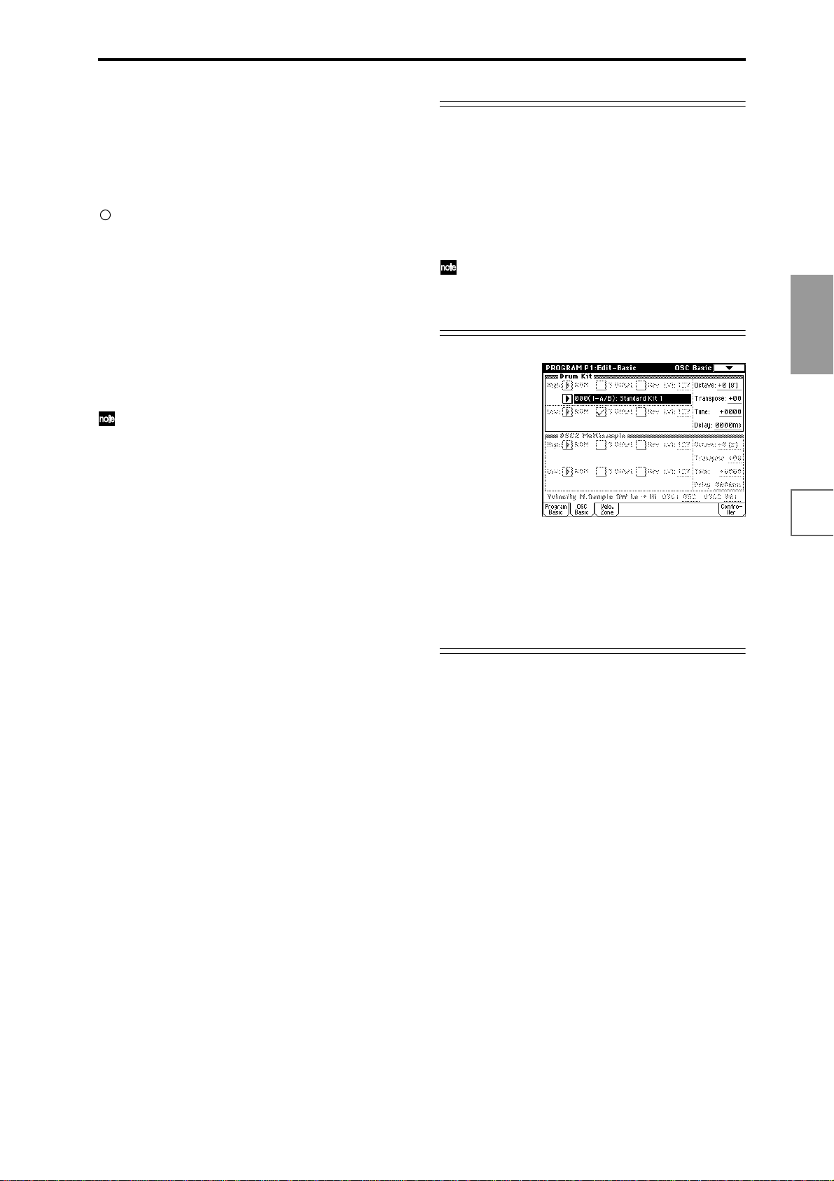
Additional multisamples can be added by installing EXBPCM series options. Data sampled on the TRITON STUDIO can also be used as a multisample.
Selecting a multisample
The multisample will determine the basic character of the
program.
Use “High MS Bank” to select the multisample bank,
and use “High Multisample” to select the multisample.
If the “High MS Bank” is ROM, you can select preset
multisamples. “High Multisample” can be selected
from a range of 000–424. (☞VNL)
If “High MS Bank” is RAM, you can select multisamples that were sampled on the TRITON STUDIO or
loaded in from media. Select from 000–999 for “High
multisample.”
If “High MS Bank” is Piano, you can select one of the
large preset piano multisamples. Select from 000–003
for “High Multisample.”
If “High MS Bank” is set to ROM, pressing the
“High Multisample” popup button will display all
internal ROM multisamples, organized into 15 categories. Use the tabs located at the left and right to
select the desired category, and select a multisample
from within that category.
High Multisample and Low Multisample
If you specify a High and Low multisample for an oscillator, either the High or the Low multisample will sound
depending on the velocity of the note (i.e., the strength at
which you play the keyboard). This function is called
velocity multisample switching.
1 Specify different multisamples for “High Multisam-
ple” and “Low Multisample.”
2 Specify a velocity value for “Velocity M.Sample SW
Lo→Hi.”
Notes played on the keyboard at a velocity less than
the value you specify will sound the Low multisample;
velocities at or above this velocity value will sound the
High multisample.
For example if you set “Velocity M.Sample SW
Lo→Hi” to 100, playing the keyboard softly will sound
the “Low multisample,” and playing strongly will
sound the “High multisample.”
3 Adjust the “Lvl” (Level) for High and Low multisam-
ples to set their volume balance.
If you do not wish to use this function, set the “Veloc-
ity M.Sample SW Lo→ Hi” value to 001. Only the
High multisample will sound.
Rev (Reverse) check box
If this is checked, the multisample will be played backward. This can produce interesting results when used on
sound-effects, etc. Normally you will not check this.
When “Oscillator Mode” = Double
To use OSC2, set “Oscillator Mode” to Double in the Program Basic page.
In the same way as for OSC1, you can set High and Low
multisamples for OSC2.
The playback pitch can be set independently. By using the
same multisample with slightly different “Tune” settings,
you can “detune” the oscillators to produce a richer
sound.
It will be convenient to use the page menu command
“Copy Oscillator” to make the oscillator settings
match each other.
When “Oscillator Mode” = Drums
In the Program Basic page, set “Oscillator Mode” to
Drums. When this is set to Drums, you will be able to cre-
ate a drum program.
This will select a drum kit instead of a multisample. TRITON STUDIO provides twenty factory preset drum kits
that are suitable for a wide variety of music. (☞VNL)
Here you can only select a drum kit. To edit or create a
drum kit, use Global P5: Drum Kit (☞p.128).
The following multisamples or drum kits can be used for
the oscillator.
• 425 internal multisamples (ROM)
• Multisamples that you sampled (RAM)
(Programs can be created from multisamples/samples
that you sampled in Sampling mode etc. or loaded
from media in Disk mode.)
• Four internal piano multisamples (Piano)
• Expansion multisamples (if a EXB-PCM option is
installed)
• Nine internal drum kits (ROM)
• 144 user drum kits created in Global mode
(Drum samples can be freely assigned to each key to
create a drum kit. For the sound of each key, you can
make filter and amp settings, and specify routing to the
effects and to the individual audio outputs.)
Basic functions
Saving dataLoading dataProgram
settings
settings
Combination
songs
Producing
settings
Sampling
CD
Creating a
SMF
playback
System
settings
settings
Drum kit
settings
Arpeggiator
69
Effects
settings
Other
functions
Page 78
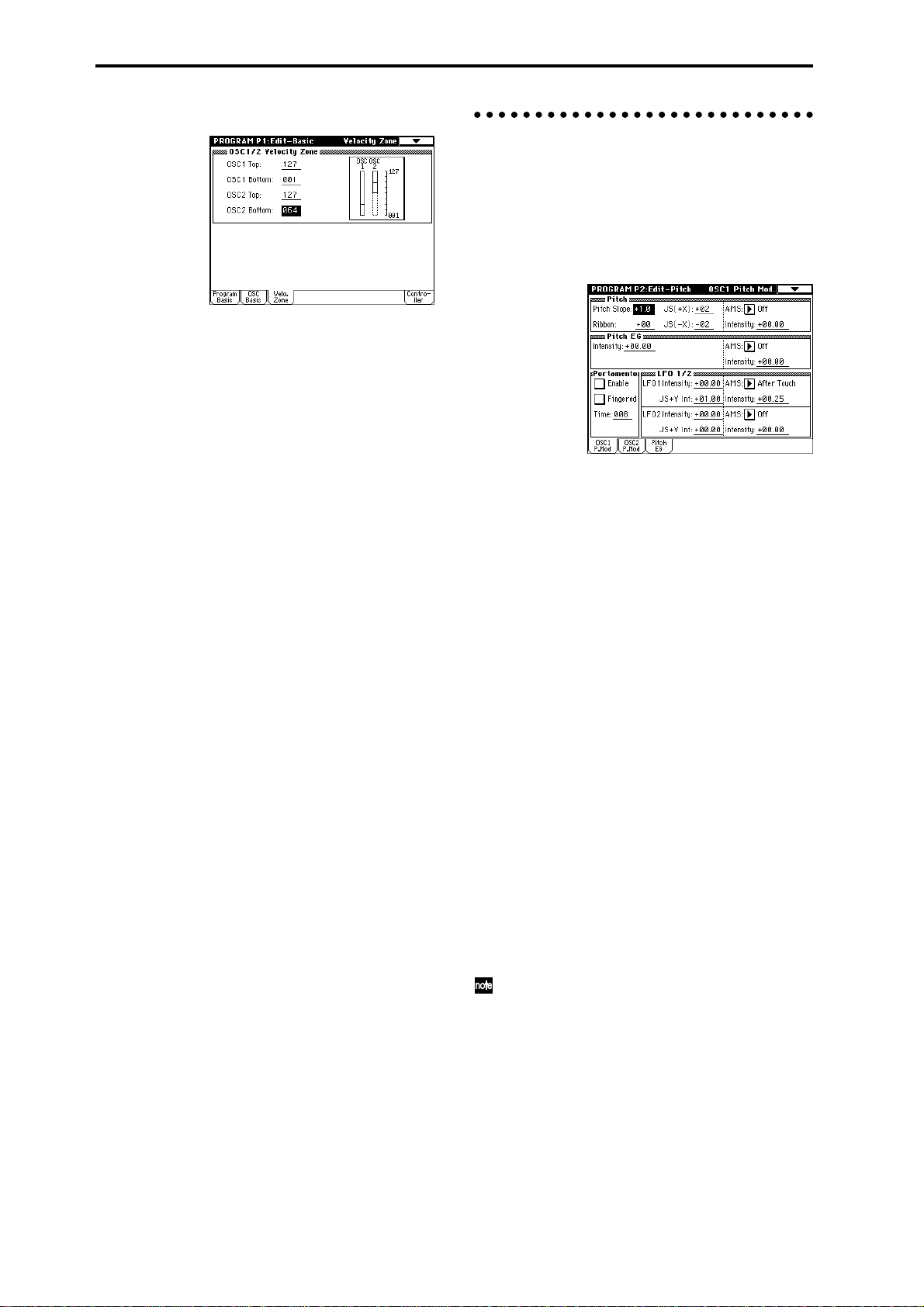
Velocity Zone page
Here you can specify the range of velocities for each oscillator. In the example shown above, the velocity ranges are
as follows.
• OSC1 will sound at all velocity values.
• OSC2 will sound only on strongly played notes (64
and above).
• You can use Velocity Multisample Switching in
addition to this parameter (☞“High Multisample,
Low Multisample”). For this example, set “OSC1” in
“Velocity M.Sample SW Lo→Hi” to 32 and “OSC2” to
096. The settings are shown as vertical lines in the
velocity zone display.
In this example, the multisamples will sound over four
levels.
Velocity values 001–031: sounds only the OSC1 Low
multisample.
Velocity values 032–063: sounds only the OSC1 High
multisample.
Velocity values 064–095: sounds the OSC1 High multi-
sample and the OSC2 Low
multisample.
Velocity values 096–127: sounds the OSC1 High multi-
sample and the OSC2 High
multisample.
Controller Setup page
For each program, this tab lets you make settings for the
[SW1] and [SW2] key, and for the B-mode of REALTIME
CONTROLS knobs [1]–[4] (☞p.145, PG p.12, 249, 250)
Pitch settings P2: Edit-Pitch
Here you can specify how the pitch of the multisample
assigned to each oscillator will change. Pitch EG and LFO
settings allow the pitch to varied over time. The OSC1
P.Mod page is valid when “Oscillator Mode” is set to Sin-
gle or Drums.
OSC1 Pitch Mod. page
Pitch
The “JS (–X)” and “JS(+X)” settings specify the amount of
pitch change (in semitones) that will occur when MIDI
pitch bend messages are received or when the joystick is
moved to left or right. A setting of +12 allows the pitch to
be controlled a maximum of one octave upward; a setting
of –12 allows the pitch to be controlled a maximum of one
octave downward.
“Ribbon” specifies the amount of pitch change (in semitones) that will occur when MIDI control change (CC) #16
messages are received or when the ribbon controller of a
TRITON STUDIO or other MIDI-connected instrument is
moved to left or right. With a setting of +12, the pitch will
be raised one octave at the far right of the ribbon controller, and will be lowered by one octave at the far left of the
ribbon controller.
Pitch EG
When the “Intensity” value is set to +12.00, the pitch EG
specified in the Pitch EG page will produce a maximum of
±1 octave of pitch change.
70
Portamento
If “Enable” is checked, portamento will be applied.
Portamento makes the pitch change smoothly when you
play the next note before releasing the previous note.
The “Time” parameter specifies the portamento time. As
this value is increased, the pitch will change over a longer
time. With a value of 000, there will be no portamento.
If Porta.SW CC#65 is assigned as the function of
[SW1] or [SW2] key, the portamento effect can be
switched on/off by [SW1] or [SW2] key.
LFO 1/2
An LFO can be used to cyclically modulate the pitch (a
“vibrato” effect).
“LFO 1/2 Intensity” sets the depth to which the LFO spec-
ified in P5: Edit-Common LFO will affect the pitch. With a
setting of +12.00, vibrato will produce a maximum of ±1
octave of pitch change.
“JS+Y Int” specifies the amount of vibrato that the LFO
will produce when the joystick is pushed away from yourself.
Page 79
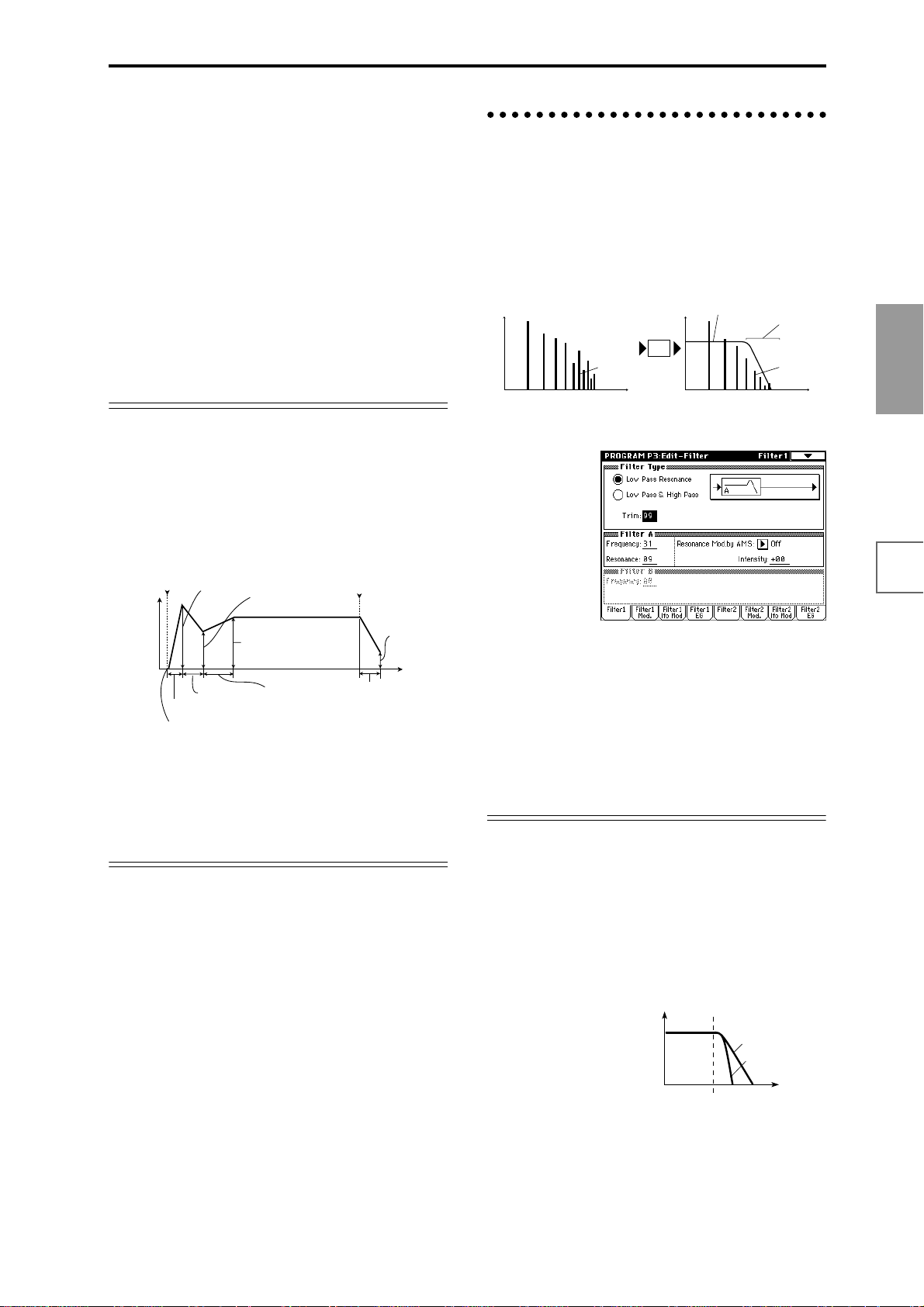
“Intensity (AMS Intensity)” specifies the depth of vibrato
that will be applied by the LFO when an AMS (Alternate
Modulation Source) is used. For example if “AMS (LFO1
AMS)” is set to After Touch and you set an appropriate
value for “Intensity (AMS Intensity),” vibrato will be
applied when you apply pressure to the keyboard or
when MIDI aftertouch messages are received.
Pitch EG page
Here you can adjust the settings for the pitch EG.
When you wish to create sound effects etc., set the pitch
EG to make major changes in pitch over time.
To realistically simulate the slight change in pitch that
occurs when a string is plucked or at the attack of a brass
or vocal sound, you can use the EG to create a subtle
change in pitch at the attack (☞PG p.12).
EG and LFO
By using an EG (envelope generator) to apply time-varying change or by using an LFO (Low Frequency Oscillator) to apply cyclic change to pitch, filter, or amp, you can
create changes in the pitch, tone, or volume.
EG (Envelope Generator)
TRITON STUDIO provides a Pitch EG, Filter EG, and
Amplifier EG, which produce time-varying changes in
pitch, tone, and volume respectively.
Attack Level
note-on note-off
Level
Break Level
Filter settings P3: Edit-Filter
The filter allows you to diminish or emphasize specified
frequency areas of the multisample selected for the oscillator.
The tone of the sound will depend significantly on the
filter settings.
TRITON STUDIO provides Filter 1 for OSC1 and Filter 2
for OSC2. For each of these filters, you can select from two
types (Low Pass Resonance or Low Pass & High Pass).
Filter 2 can be used if “Oscillator Mode” is set to Double.
Level
Filter1 page
Overtones included
in the original multisample
Frequency (pitch)
Level
Filter
Filter characteristics
This area of
overtones will
be diminished
Overtones after
passing through
the filter
Frequency (pitch)
Basic functions
Saving dataLoading dataProgram
settings
Decay Time
Attack Time
Start Level
Sustain Level
Slope Time
Release Time
Release Level
Time
LFO (Low Frequency Oscillator)
For each oscillator, TRITON STUDIO provides two LFO’s
that can be used to apply cyclical change in pitch, tone,
and volume.
Examples of this are vibrato (cyclical change in pitch),
wah (cyclical change in tone), and tremolo or auto-pan
(cyclical change in volume).
Filter Type, Filter A, Filter B
Selects the type of filter, and specify the “Frequency” (cutoff frequency) and “Resonance” (resonance level).
• Low Pass Resonance (24 dB/oct low pass filter with
resonance): Make settings for filter A.
• Low Pass & High Pass (12 dB/oct low pass filter and
12 dB/oct high pass filter in series connection): Make
low pass filter settings in filter A, and high pass filter
settings in filter B.
Low pass filter
This is the most common type of filter, which allows the
low frequency range to pass and cuts the high frequency
range. When the overtones of the high range are cut, a
bright sound will become darker (more mellow).
24 dB/oct and 12 dB/oct refer to the steepness of the cut.
24 dB/oct means that the gain will decrease 24 dB in one
octave (i.e., as the frequency doubles). A 12 dB/oct filter
would decrease the gain 12 dB in one octave. The 24 dB/
oct filter produces a steeper cut.
Low Pass
Level
12dB/oct
24dB/oct
Frequency
settings
Combination
songs
Producing
settings
Sampling
CD
Creating a
SMF
playback
System
settings
settings
Drum kit
settings
Arpeggiator
71
Effects
settings
Other
functions
Page 80

High pass filter
This type of filter allows the high frequency range to pass
and cuts the low frequency range. Use this when you wish
to make the sound thinner. However if the cutoff frequency (Frequency) is raised excessively high, the volume
will become very low.
High Pass
Level
12dB/oct
Frequency
Filter EG
Adjusts the effect produced by the filter EG, whose settings are made in the EG page.
• Use the “Velocity to A” and “Velocity to B” settings to
specify the effect of velocity on the filter EG.
• Use the “Intensity to A” and “Intensity to B” settings
to specify the depth of the filter EG.
•“Into A (AMS Int. to A)” and “Into B (AMS Int. to A)”
adjust the effect that AMS will have on the filter EG
depth.
These three settings will determine the depth of the
tonal change produced by the filter EG.
Resonance
When “Resonance” is set to a higher value, the overtones
in the region of the cutoff frequency will be boosted as
shown in the diagram below, giving a distinctive character to the sound.
When resonance is applied
Low Pass
Level
Low resonance value High resonance value
Filter1 Mod. page
Filter A/B Modulation
Set this when you wish to produce tonal change by using
controllers etc. to vary the cutoff frequency.
Filter1 LFO Mod. page
Indicates settings that allow the LFO to produce cyclic
changes in tone (a “wah” effect).
“Intensity to A (LFO Int. to A)” and “Intensity to B (LFO
Int. to B)” specify by how much the LFO will change the
tone.
“JS-Y Intensity to A” and “JS-Y Intensity to B” specify
the depth of the wah effect that will be produced by the
LFO when the joystick of TRITON STUDIO is moved
toward yourself, or when CC#2 is received.
“Intensity to A (LFO1 AMS Int.to A)” and “Intensity to B
(LFO1 AMS Int. to B)” specify the depth of the wah effect
that will be produced by the LFO when “AMS (LFO1
AMS)” is used. For example if “AMS (LFO1 AMS)” is set
to After Touch, applying pressure to the keyboard of the
TRITON STUDIO, will produce a wah effect.
Filter1 EG page
Indicates settings for the filter EG, which controls timevariant changes in tone. Make settings for the EG here,
and set the depth of its effect in the Filter1 Mod. page Fil-
ter EG parameter (☞PG p.19).
Controllers and the filter EG can be used to modulate the
filter cutoff frequency that was specified in the Filter1
page. By using a controller to vary the tone or by using an
EG to create time-varying changes, you can add a rich
variety of tonal change to the sound.
Keyboard Track
This varies the cutoff frequency according to the position
of the key on the keyboard that you play.
• When “Ramp Low” is set to a positive (+) value, the
cutoff frequency will rise as you play lower on the
keyboard, making the sound brighter. When set to a
negative (–) value, the cutoff frequency will fall as you
play lower on the keyboard, making the sound darker.
• When “Ramp High” is set to a positive (+) value, the
cutoff frequency will rise as you play higher on the
keyboard, making the sound brighter. When set to a
negative (–) value, the cutoff frequency will fall as you
play higher on the keyboard, making the sound
darker.
•“Intensity to A” and “Intensity to B” adjust the effect
that keyboard tracking will have on filters A and B
(☞PG p.17).
72
Filter EG and Amplifier EG
When the Filter EG changes the cutoff frequency, the tone
will change. However depending on the volume changes
produced by the Amplifier EG, this can be heard in different ways. For example by changing the speed at which the
tone and volume begin (attack) or decay, you can significantly vary the character of the tonal change. It is a good
idea to adjust the changes of both the Filter EG (tone) and
the Amplifier EG (volume) as you proceed with editing.
(☞“Amp1 EG page)
Amplifier settings P4: Edit-Amp
These settings affect the volume. Here you can adjust the
way in which the Amp EG and LFO produce time-varying
and cyclic changes in volume, and how the controllers etc.
will affect the volume.
Amp1 applies to OSC1, and Amp2 applies to OSC2.
Amp2 can be used if “Oscillator Mode” is set to Double.
Page 81

For example, the volume of a piano note begins at a high
volume the instant you play the note, and then decreases
gradually. The volume of an organ note remains constant
as long as you continue pressing the key. The volume of a
note on a violin or wind instrument can be varied during
the note by the musician (i.e., by regulating the amount of
pressure on the bow or the force of the breath).
Volume
Piano
Volume decays gradually
Volume
Organ
Volume remains constant
until note is released
Amp Mod. page
Time
Time
Amp1 Level/Pan page
Amp Level
Adjusts the volume of the sound that has passed through
the oscillator, filter, and amp.
Pan
Specifies the pan (stereo position) after the signal has
passed through the oscillator, filter, and amp. Normally
you will set this to C064. If “Oscillator Mode” is Double
and you wish to create a sense of stereo, set the Amp1
Level/Pan page and Amp2 Level/Pan page parameter
“Pan” to left and right for oscillators 1 and 2 respectively.
With a setting of Random, the pan will change randomly
each time you play a note on TRITON STUDIO, producing an interesting effect.
AMS (Pan AMS), Intensity
“Intensity” specifies the depth of the panning effect that
will occur when “AMS (Pan AMS)” is in use.
If you set “AMS (Pan AMS)” to Note Number, the pan
will change according to the keyboard position at which
you play a note on a TRITON STUDIO. With a setting of
LFO1 or 2, the sound will sweep from side to side (auto
pan). Other settings allow you to move the oscillator pan
by operating a controller.
Use DKit Setting
This is valid when “Oscillator Mode” is set to Drums. If
this is checked, the pan location specified by the Drum Kit
for each drum sound will be used. If this is unchecked, all
drum sounds will sound at the same location. Preload and
GM drum kits are set to stereo settings. Normally you will
leave this checked.
Keyboard Track
This lets you vary the volume relative to the position of
the key you are playing on the keyboard.
• When “Ramp Low” has a positive (+) value, the
volume will increase as you play lower on the
keyboard. With a negative (–) value, the volume will
decrease as you play lower on the keyboard.
• When “Ramp High” has a positive (+) value, the
volume will increase as you play higher on the
keyboard. With a negative (–) value, the volume will
decrease as you play higher on the keyboard.
Amp Modulation
“Velocity Intensity” is used by most programs to decrease
the volume of softly played notes and increase the volume
of strongly played notes, and the Amp Modulation parameter adjusts the depth of this control. Normally you will set
Amp Modulation to positive (+) values. As this setting is
increased, there will be greater volume difference between
softly played and strongly played notes.
LFO1/2
Specifies how the LFO’s will produce cyclic changes in
volume (tremolo effect).
The volume will be affected by the LFO(s) for which you
set an “LFO1 Intensity”, “LFO2 Intensity” value.
“Intensity (AMS Intensity)” adjusts the depth by which
the tremolo effect produced by the LFO will be affected
when you assign an “AMS (LFO1 AMS, LFO2 AMS).”
For example if you set “AMS” to JS-Y: #02, tremolo will
be applied when you move the joystick of TRITON STUDIO toward yourself, or when CC#02 is received.
Amp1 EG page
Here you can make settings for the amp EG, which
changes the volume over time.
Every instrument has its own characteristic curve of volume change. This is part of what gives each instrument its
identifiable character. Conversely, by applying a stringstype Amp EG curve to an organ-type multisample, you can
produce a sound with a character unlike a typical organ.
Piano
Organ
Basic functions
Saving dataLoading dataProgram
settings
settings
Combination
songs
Producing
settings
Sampling
CD
Creating a
SMF
playback
System
settings
settings
Drum kit
settings
Arpeggiator
Effects
settings
Strings
73
Other
functions
Page 82

LFO settings P5: Edit-Common LFO
For each oscillator, you can use two LFO (Low Frequency
Oscillator) units: LFO1 and LFO2. You ar e free to select the
type of each LFO and set its speed.
The depth of the LFO1 and LFO2 that you specify here is
adjusted by the settings of the P2: Edit-Pitch, P3: Edit-Filter and P4: Edit-Amp pages.
OSC1 LFO1, OSC1 LFO2, OSC2 LFO1, OSC2 LFO2
“Waveform” selects the type of LFO. You can choose from
a variety of waveforms, including standard waveforms
such as Triangle, Saw, Square, and Sine, as well as Step
or Random PG waveforms that produce a sample-andhold effect (☞PG p.25).
You can create a wide variety of effects by adjusting the
“Offset,” “Fade,” and “Delay” settings, and by changing
the sign (+/–) of the “Intensity” setting in the P2: EditPitch, P3: Edit-Filter and P4: Edit-Amp pages. “Fre-
quency” specifies the speed of the LFO.
Frequency Modulation
“AMS” can be used to vary the LFO speed. This lets you
change the LFO speed by operating a controller, or by the
EG or Keyboard Track settings.
Master Effect settings P9: Edit-Master Effect
Here you can select master effects and make settings for
them. The master EQ is also set here (☞p.141).
More about Alternate Modulation
Alternate Modulation is a type of modulation that can be
used to control various aspects of the sound.
AMS (Alternate Modulation Source) refers to any of the
numerous sources that can provide alternate modulation,
and includes controllers that you operate physically such
as the joystick and realtime controllers, incoming MIDI
data, as well as modulators such as the EG or LFO.
Since TRITON STUDIO allows you to apply modulation
to a modulator, this type of control is referred to as “alternate modulation.”
Intensity is a parameter that sets the degree (speed or
depth) to which AMS will control alternate modulation.
Combinations of modulations that are frequently used in
synthesizer performance (such as using the joystick to
vary the pitch) are also provided as special parameters
separate from alternate modulation.
TRITON STUDIO provides 29 types of alternate modulation.
In single mode you can use 29 alternate modulation destinations of 29 types, and in double mode you can use 55
alternate modulation destinations of 29 types.
There are 42 AMS sources. (However depending on the
type of modulation, some sources cannot be selected.)
For details on alternate modulation and AMS, refer to PG
p.241.
Frequency MIDI/Tempo Sync.
If “MIDI/Tempo Sync” is checked, the “Frequency” set-
ting will be ignored, and the LFO will synchronize to the
tempo of the sequencer and arpeggiator. This lets you produce vibrato, wah, auto-pan, or tremolo effects that are
synchronized to the playback speed of the sequencer or
arpeggiator.
Arpeggiator settings P7: Edit-Arpeggiator
Here you can make arpeggiator settings (☞p.130).
Insert Effect settings P8: Edit-Insert Effect
Here you can select insert effects and make settings for
them. You can also specify the oscillator routing (the signal sent to the insert effects, master effects, and independent outputs) (☞p.140).
Suggestions on using alternate modulation
When making settings for alternate modulation, think of
the effect that you wish to produce, what type of modulation will be necessary to produce that effect, and what
parameter of the oscillator, filter, or amplifier needs to be
controlled. Then select a source (“AMS”) and set the
“Intensity.” If you proceed logically in this way, you will
achieve the desired effect.
For example if you want to “control a guitar-like sound so
that it appears to be approaching feedback when the joystick is moved away,” you will make settings so that the
joystick controls filter modulation or the resonance level.
74
Page 83

Combination settings
Combination editing is performed in Combination mode,
just as combinations can be selected and played in Combination mode.
Combination mode consists of the P0: Play–P9: Edit-Master FX pages.
In P0: Play, you can select and play combinations. You can
also perform simple editing, make arpeggiator settings,
and make settings for audio input and sampling. (☞p.24,
31, 35)
In P1: Edit-Program/Mixer–P9: Edit-Master FX, you can
edit the parameters of the combination you selected in P0:
Play.
You can perform sampling/resampling in Combination mode (☞p.45, 102). You can also apply the TRITON STUDIO’s effects to an external audio input, for
a wide range of possibilities. (☞p.143)
How a combination is organized
A combination consists of a variety of parameters that can
be accessed in P1: Edit-Program/Mixer–P9: Edit-Master
FX. The diagram below shows how a combination is
structured.
Basic combination editing
You can edit the preloaded combinations (banks INT-A–
INT-D) with which the TRITON STUDIO is shipped, or
start with an initialized combination (banks INT-E, EXBA–EXB-G) to create your own original combination.
Original programs using sample waveforms/multisamples you sampled on the TRITON STUDIO (or
loaded into memory via Disk mode) can also be used
in a combination.
If you wish to save an edited combination in internal
memory, you must write it. (☞p.56)
If a program being edited in Program mode is used in
a combination, it will sound according to the settings
being edited.
In the following pages, we will explain how to edit some
of the major parameters, and explain their functions.
For a more detailed explanation of the parameters, refer to
PG p.33 and following.
Combinations that you edit or create from scratch can be
written into the 1,536 combination memory areas (internal
memory) of banks INT-A–INT -E and EXB-A–EXB-G. They
can also be stored and managed on various types of
media. (☞p.59)
Suggestions for editing procedure
The parameters of each timbre are set in P1: Edit-Program/Mixer–P9: Edit-Master FX. This is where you create
the basic combination consisting of the programs you
select here.
First use P1: Edit-Program/Mixer to select the program
for each timbre, and then use P4: Edit-Zone/Ctrl to specify the range in which each program will sound (layer,
split, velocity switch, etc.). Then adjust the volume of each
timbre, and set various other parameters.
To add finishing touches to the sound, you can assign
insert effect settings (in P8: Edit-Insert FX) and master
effect and master EQ settings (in P9: Edit-Master FX) that
are different from the effect settings of Program mode. In
addition, you can make arpeggiator settings (in P7: EditArp.) and controller settings (in P4: Edit-Zone/Ctrl) to
create the finished combination.
By using the page menu command “Solo Selected
Timbre”, you can listen only to the selected timbre.
This is a convenient way to audition individual
sounds of timbres that are layered. (☞PG p.35)
Basic functions
Saving dataLoading dataProgram
settings
settings
Combination
songs
Producing
settings
Sampling
CD
Creating a
Timbre1
Program
Timbre2
Program
Timbre3
Program
Timbre4
Program
Timbre8
Program
Parameters
Parameters
Parameters
Parameters
Parameters
Routing : P8-1
Timbre
Insert Effect
Master Effect
Individual Outputs
Insert Effect 1 ... 5 : P8
Controller Setup : P4- 4
Arpeggiator : P7
Master Effect 1, 2 : P9
MasterEQ : P9
P1–1 or P2–2 etc. indicate pages or tab screens used on this instrument for editing.
AUDIO OUTPUT
L/MONO, R
AUDIO OUTPUT
INDIVIDUAL 1,2,3,4
75
SMF
playback
System
settings
settings
Drum kit
settings
Arpeggiator
Effects
settings
Other
functions
Page 84

Layer, split, and velocity switch
Within a combination, you can use key position and velocity to determine which program will sound.
The programs assigned to each timbre can sound in three
ways: as part of a layer, a split, or a velocity switch. A
combination can be set to use any one of these methods,
or to use two or more of these methods.
Layer
Layer refers to settings which cause two or more programs to sound simultaneously when a note is played.
Program A
Program B
Layer:
Two or more programs sound
simultaneously.
Split
Split refers to settings which cause different programs to
sound on different areas of the keyboard.
Program A
Program B
Split:
Different programs will sound in
different areas of the keyboard.
Velocity switch
Velocity Switch refers to settings which cause different
programs to sound depending on the velocity (keyboard
playing dynamics).
Program B
Program A
On TRITON STUDIO, you can use a different program for
each of up to eight timbres, and combine two or more of
the above methods to create even more complex setups.
Program A
Program B
Program D
Program C
As an additional possibility , you can set the slope for a key
zone or velocity zone so that the volume diminishes gradually. This lets you change a split into a keyboard cross-
fade, or a velocity switch into a velocity crossfade.
Program A
Program B
Strong
Keyboard playing
dynamics
Soft
Velocity Switch:
Keyboard playing dynamics
(velocity) switches between
different programs.
Strong
Keyboard playing
dynamics
Soft
Example:
B and C/D are split. In the lower
keyboard range, A and B are
layered. In the higher keyboard
range, C and D are switched by
velocity and layered with A.
Keyboard X-Fade (keyboard
crossfade):
As you play from low notes
to high notes, the volume of
A will fade out, and the
volume of B will fade in.
The Compare function
As you are editing a combi, you can use the [COMPARE]
key to listen to the previously saved version (as it was
before you began editing). Pressing [COMPARE] again
(the light goes dark) returns you to the version you are
editing.
If you continue editing when the [COMPARE] key
LED is lit, the LED will go dark, and the current setting will now be the sound that is recalled when the
[COMPARE] key LED is dark.
Timbre 1–8 program, pan and volume P1: Edit-Program/Mixer
Here you can assign programs to each timbre 1–8, and set
the pan and volume for each one. (These settings can also
be made in the Program Select and Mixer pages of P0:
Play.)
Edit-Program/Mixer page
Category, Program Select (Bank/Program)
Assigns a program to each timbre.
When the “Bank/Timbre Program” select menu is
displayed, you can select programs by bank.
When the “Category/Timbre Program” select menu
is displayed, you can select programs from the 16 categories. (☞p.35)
You can also use the BANK [INT-A]–[EXB-G] keys to
select the bank of the program.
If you wish to select programs by receiving MIDI program changes, do so in P0: Play.
Pan
Specifies the panning (stereo position) for each timbre. A
setting of C064 will reproduce the oscillator pan setting of
the program. Adjusting this parameter will move the
sound to left or right while preserving the pan relationship between the oscillators. A setting of L001 is far left,
and R127 is far right.
76
Volume
Adjusts the volume of each timbre.
Create the overall sound by adjusting the volume balance
between timbres. The “Volume” setting is an important
aspect of creating the sound, and this setting will have a
significant effect on the overall impression produced by
the Combination.
Page 85

Settings for status, MIDI channel, and pitch parameters P2: Edit-Trk Param
MIDI Ch page
Status
Here you can specify the MIDI status of the internal tone
generator assigned to each timbre. Normally when playing the internal tone generator of TRITON STUDIO, you
will set this to INT. Set this to Off for timbres that you are
not using. With settings of Off, EXT, or EX2, TRITON
STUDIO will not sound. With settings of EXT or EX2, you
can control an external tone generator connected via
MIDI. (☞PG p.38)
MIDI Channel
Timbres that you wish to play from TRITON STUDIO’s
keyboard must be set to the global MIDI channel. Your
playing on the keyboard is transmitted on the global MIDI
channel, and will sound any timbre that matches this
channel. Normally you will set this to Gch. When this is
set to Gch, the MIDI channel of the timbre will always
match the global MIDI channel, even if you change the
global MIDI channel.
On some preloaded combinations that use the arpeggiator, timbres assigned to the arpeggiator may not
have a “Status” of INT and “MIDI Ch” of Gch.
The reason for this is that these settings ar e for timbres
that sound only when the arpeggiator is on. This is a
very useful technique for creating combinations that
use the arpeggiator. Refer to “Arpeggiator settings in
Combination and Sequencer modes” (
p.44), and study the relationship between arpeggiator
assignments, “Status,” and “MIDI Channel.”
☞p.132
, PG
OSC page
Force OSC Mode
Normally you will set this to PRG (the oscillator will play
as set by the program settings).
If you wish to force a polyphonic program to sound
monophonically, set this either to MN (Mono) or LGT
(Legato). Conversely , set this to Poly if you wish to force a
monophonic program to play polyphonically (☞PG p.38).
OSC Select
Normally you will set this to BTH (Both).
If the timbre is using a program whose “Oscillator Mode”
is Double, and you want only OSC1 or OSC2 (not both) to
sound, set this to OSC1 (only OSC1 will sound) or OSC2
(only OSC2 will sound).
Portamento
Normally you will set this to PRG.
If you want to overide the portamento setting specified in
the program assigned to the timbre to be forced off, set
this parameter to Off. Conversely, if you want to force the
portamento to be on, or to change the portamento time,
set this to a value of 001–127 to specify the portamento
time.
Pitch page
Basic functions
Saving dataLoading dataProgram
settings
settings
Combination
songs
Producing
settings
Sampling
CD
Creating a
SMF
playback
Bank Select (when status=EX2)
This setting is valid when “Status” is set to EX2. It specifies the Bank Select message that will be transmitted from
TRITON STUDIO.
Transpose, Detune (BPM Adjust)
These parameters adjust the pitch of the timbre.
• In a layer-type combination, you can set two or more
timbres to the same program, and create a richer
sound by using “Transpose” to shift their pitch apart
by an octave or by using “Detune” to create a slight
difference in pitch between the two.
• In split-type combinations, you can use “Transpose”
to shift the pitch (in semitone units) of the programs
specified for each key zone.
• If you wish to change the playback pitch of a drum
program, use “Detune.” If you change the
“Transpose” setting, the relationship between notes
and drum sounds will change.
77
System
settings
settings
Drum kit
settings
Arpeggiator
Effects
settings
Other
functions
Page 86

Adjusting the BPM of multisamples or samples created in Sampling mode
If a timbre’s program uses multisamples or samples that
you created in Sampling mode (or loaded in Disk mode)
at a specific BPM value, you can use the page menu command “Detune BPM Adjust” to call up a new BPM value.
This changes the BPM by adjusting the playback pitch.
(☞PG p.39)
For example if you selected a bass program for timbre 1
and a piano program for timbre 2 to create a split-type
combination, you could make the following settings so
that pressing the connected damper pedal would apply
the damper effect only to the piano program of timbre 2.
Set the P3: Edit-MIDI Filter-1 “Enable Damper”
parameter
Timbre 1 “Enable Damper”: unchecked
Timbre 2 “Enable Damper”: checked
Other page
Delay [ms]
Specifies the amount of time before the program assigned
to each timbre will sound. Specifies the time from when
you play the keyboard until the program will sound.
If you select KeyOff for this parameter, the timbre will
sound when the note is released.
Use Program’s Scale, Scale
Specifies the scale for each timbre. If you check “Use Pro-
gram’s Scale,” the scale specified by the program will be
used. Timbres for which this is not checked will use the
Scale setting.
Layer, split, and velocity switch settings/Controller settings P4: Edit-Zone/Ctrl
Key Zone page (Key zone settings)
Indicates settings such as layer, split, and keyboard crossfade.
Specifies the range of notes that will be sounded by each
timbre. Each area that sounds a timbre is referred to as a
Key Zone. By setting key zones, you can create a combination in which different programs sound in different
areas of the keyboard.
By combining key zones specified for each timbre, you
can create layered or split combinations.
The upper and lower limits for the key zone of each timbre are set by the “Top Key” and “Bottom Key” respec-
tively.
For example in the following diagram, timbres 1–3 are set
to create a layered and split combination. This is specified
by the key zone settings.
Timbres 2 and 3 create a layer. Timbre 1 and timbres 2/3
are split between the B3 and C4 note numbers.
Timbre 2
Timbre 3
Brass
Strings
PianoTimbre 1
MIDI filter settings
P3: Edit-MIDI Filter
For each MIDI Filter item, you can specify whether or not
the corresponding MIDI message will be transmitted and
received. The checked items will be transmitted and
received.
MIDI filter does not turn the function itself on/off,
but specifies whether or not that MIDI message will
be transmitted and received. For example if portamento is on, portamento will be applied to the sound
of TRITON STUDIO even if “Portamento SW CC#65”
is unchecked.
C–1 C4 G9B3
As an example here, we will explain how to create a combination like the one shown above.
1 In the P0: Play, Program Select page or the P1: Edit-
Program/Mixer page, use the “Program Select” area to
select the program that will be used for each timbre
1–3.
Select a piano program for timbre 1.
Select a brass program for timbre 2.
Select a strings program for timbre 3.
2 In the MIDI Ch page of P2: Edit-Trk Param, set “Sta-
tus” to INT for all the timbres that you wish to use,
and set “MIDI Channel” to either Gch or to match the
global MIDI channel (a “G” will be displayed after
the channel number).
3 In the Key Zone page of P4: Edit-Zone/Ctrl, set “Top
Key” and “Bottom Key.”
Set timbre 1 to a “Top Key” of G9 and a “Bottom Key”
of C4.
Set timbres 2 and 3 to a “T op Key” of B3 and a “Bottom
Key” of C–1.
78
Page 87

You can also enter these values by holding down the
[ENTER] key and playing a note on the keyboard.
You can also enter these values by holding down the
[ENTER] key and playing a note on the keyboard.
Key Zone Slope
Here you can specify the range of keys over which the
original volume will be reached, starting at the top key
and bottom key.
In the case of the above example, you could set the key
zones so that a portion of timbres 1 and 2 overlaps (i.e., is
layered) with timbre 3, and set “Top Slope” and “Bottom
Slope” so that the sound changes gradually, instead of
changing suddenly between B3 and C4.
Vel Zone page (Velocity zone settings)
Here you can make settings for velocity switching and
velocity crossfading.
For each timbre, you can specify a range of velocities for
which it will sound. The range of velocities for which a
timbre will sound is called a Velocity Zone. By setting a
velocity zone, you can set up a timbre which will be
sounded only by notes played within a certain range of
velocities, and not by notes played outside this Velocity
Zone.
By combining timbres that have differing velocity zone
settings, you can create velocity switched combinations.
The upper and lower limits of the velocity zone of each
timbre are determined by the “Top Velocity” and “Bot-
tom Velocity” respectively.
The following diagram shows an example of a velocity
switched combination in velocity will switch between
timbres 1 and 2 to play different programs. Such combinations are created by setting the velocity zone.
Timbre 1
Timbre 2
Brass
Strings
127
64
Velocity
63
switch
1
Velocity Zone Slope
Here you can specify the range of values over which the
original volume will be reached, starting from the top
velocity and bottom velocity.
In the case of the above example, you could set the velocity zones of the two timbres so that they partially overlap,
and set “T op Slope” and “Bottom Slope” so that the sound
changes gradually , instead of changing suddenly between
velocity values of 63 and 64.
Control page (Controller settings)
For each combination, you can specify the functions of the
B-mode functions of REALTIME CONTROLS knobs [1]–
[4], and the [SW1] and [SW2.] (☞p.145, PG p.43, 249, 250)
Arpeggiator settings P7: Edit-Arp.
Indicates settings for the arpeggiator (☞p.132).
Insert Effect settings P8: Edit-Insert FX
Indicates the insert effects, and allows you to adjust their
settings.
Specifies the routing for each timbre (i.e., how it is sent to
the insert effect, master effects, and individual outputs).
(☞p.141)
Basic functions
Saving dataLoading dataProgram
settings
settings
Combination
songs
Producing
settings
Sampling
CD
Creating a
SMF
playback
As an example, we will explain how to create a combination like the one shown above.
1 In the P0: Play, Program Select page or the P1: Edit-
Program/Mixer, Prog page, use the “Program Select”
area to select the program that will be used for each
timbre 1 and 2.
Select a brass program for timbre 1.
Select a strings program for timbre 2.
2 In the MIDI Ch page of P2: Edit-Trk Param, set “Sta-
tus” to INT for all the timbres that you wish to use,
and set “MIDI Channel” to either Gch or to match the
global MIDI channel (a “G” will be displayed after
the channel number).
3 In P4: Edit-Zone/Ctrl Vel Zone page, set the “Top
Velocity” and “Bottom Velocity.”
Set timbre 1 to a “Top Velocity” of 127 and a “Bottom
Velocity” of 64.
Set timbre 2 to a “Top Velocity” of 63 and a “Bottom
Velocity” of 1.
Master Effect settings P9: Edit-Master FX
Indicates the naster effects, and allows you to adjust their
settings.
Here you can also make master EQ settings (☞p.142).
79
System
settings
settings
Drum kit
settings
Arpeggiator
Effects
settings
Other
functions
Page 88

Producing songs
TRITON STUDIO contains a 16-multi track MIDI
sequencer. The sequencer acts as a hub, integrating TRITON STUDIO’s numerous functions, allowing it to be
used in a variety of situations including music production
and live performance.
Sampling or resampling can be performed in
Sequencer mode (☞p.115). You can also apply the
TRITON STUDIO’s effects to an external audio input
source, for a wide range of possibilities. (☞p.143)
When you turn off the power, the settings made in
Sequencer mode and the song data, cue list data, and
any user pattern data that you recorded will not be
backed up. If you wish to keep this data, you must
save it on media (Floppy disk, hard drive etc.) before
turning off the power, or perform a MIDI data dump
to save the data on an external data filer etc.
If you wish to save the programs, track parameters,
effects, and arpeggiator function settings etc. selected
for a song as a template song, use the page menu
command “Save Template Song.”
Immediately after the power is turned on, TRITON
STUDIO will not contain any cue list data or song
data, so if you wish to playback a song on the
sequencer, you must first load data from media or
receive a MIDI data dump from a MIDI filer (☞p.63,
PG p.145, 161)
Features of the sequencer
• The sequencer lets you record a maximum of 200,000
events (note data etc.), up to 200 songs, and as many
as 999 measures per song.
• Up to 20 cue lists can be created.
A cue list is an arrangement of up to 99 songs that will
be played as a chain. You can specify the number of
times that each song will repeat. A cue list can also be
converted into a single song.
• The arpeggiator function can be used during playback
or recording.
• The RPPR (Realtime Pattern Play/Recording)
function can be used during playback or recording.
• Sixteen different template songs are built-in, and
contain program and effect settings suitable for
various musical styles. Up to sixteen original
templates that you create can be saved as user
template songs.
• Five stereo insert effects, two master effects, and a
stereo master EQ can be used for each song.
• Timing resolution is a maximum of /192.
• Sixteen tracks are provided for musical data, and a
master track contains time signature and tempo data
that controls the playback.
•A track play loop function lets you loop specified
measures independently for each track.
• 150 preset patterns ideal for drum tracks are built in.
In addition, you can create up to 100 user patterns for
each song. These patterns can be used as musical data
within a song, or can be played by the RPPR function.
• Various methods of recording are supported,
including realtime recording in which your
performance on the keyboard and controllers
(including MIDI control events) is recorded just as you
play, and step recording in which the timing, length,
and velocity of each note can be specified in the LCD
as you input the pitches from the keyboard.
• The musical data and control events that you recorded
can be edited in various ways (including event editing
and many other edit commands).
• When the “Status” of a track is set to INT or BTH, an
external sequencer can be used to play TRITON
STUDIO as a multi-timbral tone generator.
When the “Status” of a track is set to BTH, EXT, or
EXT2, the sequencer of TRITON STUDIO can play
external tone generators.
• Playback can be synchronized with an external MIDI
device.
• TRITON STUDIO’s AMS (Alternate Modulation)
capability lets you use control changes for realtime
control of the parameters of the programs used in a
program. Its MIDI Sync abilities let you synchronize
the LFO speed to changes in the tempo.
• Dmod (Dynamic Modulation) functionality lets you
control effect parameters in realtime. You can also use
MIDI Sync to synchronize the LFO speed or delay
time to changes in the tempo.
• You can assign names not only to the song, but also to
each pattern and track.
• Combination settings can be copied to a song.
• Sequencer data such as a song or cue list that you
create can be saved in TRITON STUDIO’s native
format, or transmitted as a MIDI data dump.
• A song you created can be converted into SMF
(Standard MIDI File) data. SMF songs can also be
loaded.
• The PLAY/MUTE/REC and “SOLO On/Off” let you
instantly play/mute any desired track on the fly.
• You can rewind or fast-forward while listening to the
sound.
• The [LOCATE] key lets you move quickly to a desired
location.
• Multisamples you create can be played back together
with internal programs in Sequencer mode.
The Time Slice function of Sampling mode lets you
divide a rhythm loop sample and create performance
data that corresponds to the divided samples. In
Sequencer mode you can play this performance data,
and adjust the playback tempo without affecting the
pitch of the rhythm loop sample. You can also
exchange the note numbers of the data, or modify the
timing to freely re-create new rhythm loops.
• The TRITON STUDIO provides an In-Track Sampling
function which lets you sample an external audio
source while the song plays back, and will
automatically create note data to trigger that sample at
the appropriate point during the playback of the track.
• A song you create can be resampled to the hard disk.
In Disk mode, this data can then be written to an
audio CD by using the CDRW-1 option.
80
Page 89

The structure of Sequencer mode
Patterns
The following describes the structure of Sequencer mode.
(☞diagram below)
Songs
A song consists of tracks 1–16, a master track, song
parameters such as the song name, effect, arpeggiator and
RPPR parameters, and 100 user patterns.
A maximum of 200 such songs can be created on TRITON
STUDIO.
Tracks 1–16 and the master track each consist of setup
parameters located at the start location, and musical data
within the track.
Setup parameters
Tracks 1–16
Bank/Program No.*, PLAY/MUTE/REC, Pan*, Volume*, Track Play Loop, Loop Start Measure, Loop End
Measure, Play Intro, Status, MIDI Channel, Bank Select
(When Status=EX2), Force OSC Mode, OSC Select, Portamento*, T ranspose**, Detune**, Bend Range**, Delay,
Use Program's Scale, MIDI Filter, Key Zone, Velocity
Zone, T rack Name, Arpeggiator Assign, IFX/Indiv.Out
BUS Select, Send1(MFX1)*, Send2(MFX2)*
Master track
Time signature*, Tempo*
Musical data
Tracks 1–16
Note On/Off, Program Change (including Bank
Select), Pitch Bend, After Touch (Poly After), Control
Change, Pattern No.
* When you change the setting during realtime-
recording, this will be recorded as musical data.
This allows the starting settings to be modified during the playback.
** Musical data (MIDI RPN data) can be used to
change the starting settings during playback.
For details on control changes and RPN, refer to PG
p.260, 263.
There are two types of patterns: preset patterns and user
patterns.
• Preset patterns: Patterns suitable for drum tracks are
preset in internal memory, and can be selected for any
song.
• User patterns: Each song can have up to 100 patterns.
When using a pattern in a different song, use the
Utility menu commands “Copy Pattern” or “Copy
From Song” etc. to copy the pattern. The pattern
length can be specified in units of a measure.
Each pattern consists of musical data for one track. It is
not possible to create patterns that contain multiple tracks.
These patterns can be used as track musical data by being
placed in a track (page menu command “Put to Track”) or
copied to a track (page menu command “Copy to Track”).
Alternatively, you can use a pattern with the RPPR function of a song.
Cue List
A cue list allows you to playback multiple songs in suc-
cession. The TRITON STUDIO allows you to create 20 cue
lists. Each cue list allows you to connect a maximum of 99
songs in any order, and to specify the number of times
that each song will repeat.
The page menu command “Convert to Song” lets you
convert the two or more songs in a cue list into a single
song. This allows you to use a cue list to create the backing, then convert the cue list into a song and add solo
phrases on unused tracks.
Basic functions
Saving dataLoading dataProgram
settings
settings
Combination
songs
Producing
settings
Sampling
CD
Creating a
SMF
playback
Parameter settings Musical data
Track 1
Track 2
Parameter settings Musical data
Track 3
Parameter settings Musical data
Track 4
Parameter settings Musical data
Track 5
Parameter settings Musical data
Track 6
Parameter settings Musical data
Track 7
Parameter settings Musical data
Track 8
Parameter settings Musical data
Track 16
Parameter settings Musical data
Master Track
Tempo, Time signature data
Routing : P8-1
Track
Insert Effect
Master Effect
Individual Outputs
Insert Effect 1 ... 5 : P8
Master Effect 1, 2 : P9
Pattern U00 ... U99
RPPR Setup
: P6
MasterEQ : P9
Controller Setup : P4- 4
Arpeggiator : P7
AUDIO OUTPUT
L/MONO, R
AUDIO OUTPUT
INDIVIDUAL 1,2,3,4
81
System
settings
settings
Drum kit
settings
Arpeggiator
Effects
settings
Other
functions
Page 90

Preparations for recording
On the TRITON STUDIO, “recording” is the process by
which your performance on the keyboard and controllers
is written into the tracks and patterns of a song as data.
This section explains how to make preparations for
recording a song, such as assigning a program to each
track, and setting the volume.
By loading a template song, you can easily make
appropriate settings for various styles of music.
1 Assign a program to each track.
In the Sequencer P0: Play/REC, Program T01–08/T09–
16 page, use “Program Select” to assign a program to
each track.
At this time you can press the “Category” popup and
select programs by category. (☞PG p.51)
You can also use the Utility menu command “Copy
From Combi” to copy settings from a combination
(☞p.95, PG p.52).
When assigning a program, you can use “Track
Select” to select the track for which you are making
assignments, and try playing the sound.
2 Set the pan and volume of each track.
In the Sequencer P0: Play/REC, Mixer T01–08/T09–16
page, “Pan” sets the pan of each track, and “Volume”
sets the volume of each track.
external tone generator must be set to match the “MIDI
Channel” of TRITON STUDIO tracks that are set to
EXT, EX2 or BTH.)
If “Status” is set to BTH, both the external tone generator and the TRITON STUDIO’s own tone generator
will be sounded and controlled.
If you are using the TRITON STUDIO’s Sequencer
mode as a 16-track multi-timbral tone generator, set
this parameter to INT or BTH. (☞”Status” PG p.62)
In general, you should set “MIDI Channel” to different
channels 1–16 for each track. Tracks that are sent to the
same MIDI channel will sound simultaneously when
either is recorded or played.
4 Adjust the effect settings.
Make settings for each effect in Sequencer P8: Insert
Effect and P9: Master Effect. (☞p.141, PG p.83)
5 Set the tempo and time signature.
Make these settings in Sequecner P0: Play/REC.
“ (Tempo)” sets the tempo, and “Meter” sets the time
signature. (☞PG p.49)
6 As necessary, set “Reso” to specify the quantization
resolution. (☞p.51)
7 Make other settings as necessary.
As necessary , make arpeggiator settings (Sequencer P7:
Arpggiator) and MIDI filter settings (Sequencer P3:
MIDI Filter). (☞PG p.49–86)
When you are finished making these settings, the basic
setup is complete. Record as described in “Recording
methods” (☞p.83) and following sections.
3 Specify the tone generator and MIDI channel that
will be played by each track.
In the Sequencer P2: Trk Param, MIDI Ch T01–08/T09–
16 page, “Status” specifies whether each track will
sound the internal tone generator or an external tone
generator. “MIDI Channel” specifies the MIDI channel
for each track.
If the track “Status” is set to INT, playing the track data
or operating the TRITON STUDIO’s keyboard or controllers will cause the TRITON STUDIO’s internal tone
generator to be played.
If “Status” is set to EXT, EX2, or BTH, playing the track
data or operating the TRITON STUDIO’s keyboard or
controllers will cause an external tone generator to be
sounded and controlled. (The MIDI channel of the
82
Monitoring just a specific track/Muting just a specific track (Solo/Mute functions)
The TRITON STUDIO provides a Solo function that lets
you play only a specific track 1–16, and a Mute function
that silences only specific tracks. These functions can be
used in various ways. For example you can intentionally
mute or solo specific tracks, or listen only to the rhythm
section of the previously-recorded tracks while you record
new tracks.
Let’s try out the Mute and Solo functions.
1 Load a song.
As described on p.20, load the demo songs, and select
any song.
2 Access the Sequencer P0: Play/REC, Program T01–08/
T09–16 page.
Press the SEQUENCER [START/STOP] key.
3 Press track 1 “PLAY/MUTE/REC.”
Page 91

The display will change from “PLAY” to “MUTE,” and
the playback of track 1 will no longer be heard. In this
way, the “mute” function allows you to silence a specified track until the track is un-muted.
Press track 2 “PLAY/MUTE/REC.”
The display will change, and the playback of track 2
will also be muted.
To cancel muting, press “PLAY/REC/MUTE” once
again.
4 Press track 1 “SOLO ON/OFF.”
The display will change from “SOLO OFF” to “SOLO
ON,” and this time, only the performance of track 1
will be heard. To play back only a specified track by
itself in this way is known as “soloing” the track (turning Solo on).
If both Mute and Solo are used, the Solo function will
be given priority.
5 Press track 2 “SOLO ON/OFF.”
The display will change, and only the playback of
tracks 1 and 2 will be heard.
To switch Solo off, press “SOLO ON/OFF” once
again. Press “SOLO ON/OFF” for both tracks 1 and 2.
The display will change, and the playback of tracks 1
and 2 will be muted. If the Solo function is turned off
for all tracks, playback will be according to the “PLA Y/
MUTE/REC” settings.
By using the page menu command “Solo Selected
Track,” you can listen to the sound of only the
selected track. This is convenient when you want to
set track parameters or to make effect settings. (☞PG
p.52)
Recording methods
This section describes the ways in which you can record
on the TRITON STUDIO.
Recording a track
There are two ways to record to a track: realtime recording and step recording. You can choose from six types of
realtime recording.
In addition, you can use event editing to modify data that
has been recorded or to insert data, and use track editing
operations such as Create Control Data to insert data
such as bend, after touch, and control changes.
Recording a pattern
There are two ways to record a pattern: realtime recording and step recording. For realtime recording, only one
recording type (loop) is available.
In addition, you can use event edit operations to modify
data that has been recorded or to insert data.
The page menu command “Get From Track” can be used
to take musical data from a desired area of a track, and use
it as the musical data for a pattern. Conversely, the page
menu commands “Put to T rack” and “Copy to Track” can
be used to place or to copy the musical data of a pattern in
a track.
Realtime recording on a track
This is a method of recording in which your playing on
the keyboard and your operations of controllers such as
the joystick are recorded in realtime.
This method of recording is normally used one track at a
time, and is called single track recording.
As an alternative, multitrack recording allows you to
simultaneously record multiple channels of data onto
multiple tracks. This is the method you will use when
using the RPPR function and the arpeggiator function to
record multiple tracks of musical data at once, or when
you playback existing sequence data on an external
sequencer and record it onto TRITON STUDIO’s
sequencer in realtime (☞p.85).
These settings are made in Sequencer P0: Play/REC,
Preference page “Recording Setup.”
Basic functions
Saving dataLoading dataProgram
settings
settings
Combination
songs
Producing
settings
Sampling
CD
Creating a
SMF
playback
[LOCATE] settings
By pressing the [LOCATE] key you can move to a specified location.
The location is specified by the Utility menu command
“Set Location.” You can also hold down the [ENTER] key
and press the [LOCATE] key to set the location even during playback (☞PG p.54).
When you select a song, the “LOCATE” setting will automatically be set to 001:01.000.
Normally you will leave this set to 001:01.000., to return
you to the begining of the song.
• Overwrite
With this method, the musical data previously
recorded on a track is overwritten by the newly
recorded data. When you perform overwrite recording
on a previously-recorded track, its musical data will be
deleted and replaced by the newly recorded data.
Normally you will use this method to record, and then
modify the results by using other types of realtime
recording or event editing.
1 Use “T rack Select” to select the track that you want to
record.
83
System
settings
settings
Drum kit
settings
Arpeggiator
Effects
settings
Other
functions
Page 92

2 Set the “Recording Mode” to Over Write.
3 In “Location,” specify the location at which you wish
to begin recording.
4 Press the SEQUENCER [REC/WRITE] key, and then
press the SEQUENCER [START/STOP] key.
If the “Metronome Setup” is still set to the default settings, the metronome will sound for a two-measure
pre-count, and then recording will begin.
Play the keyboard and move controllers such as the
joystick to record your performance.
5 When you finish playing, press the SEQUENCER
[START/STOP] key.
Recording will end, and the location will return to the
point at which you begin recording.
If you press the [PAUSE] key instead of the
SEQUENCER [START/STOP] key, recording will
pause. When you press the [PAUSE] once again,
recording will resume. When you are finished, press
the SEQUENCER [START/STOP] key to stop recording.
• Overdub
With this method, the newly recorded musical data is
added to the existing data.
When you perform overdub recording on a previouslyrecorded track, the newly recorded data will be added
to the previously-recorded data.
It is best to select this mode if you will be recording
additional control data, recording a drum pattern, or
recording the tempo in the master track. With this
mode, data can be added without erasing the existing
performance data.
1 Use “T rack Select” to select the track that you want to
record.
2 Set the “Recording Mode” to Over Dub.
3 For the rest of the procedure, refer to steps 3–5 of
“Overwrite.”
• Manual punch-in
While the song is playing, you can press the
SEQUENCER [REC/WRITE] key or a connected pedal
switch at the desired location to start or stop recording.
With this method, the musical data previously on the
track is overwritten by the newly recorded data.
1 Use “T rack Select” to select the track that you want to
record.
2 Set the “Recording Mode” to Manual Punch In.
3 In “Location,” specify a location several measures
earlier than the point at which you wish to begin
recording.
4 Press the SEQUENCER [START/STOP] key.
Playback will begin.
5 At the point at which you wish to begin recording,
press the SEQUENCER [REC/WRITE] key.
Recording will begin. Play the keyboard and operate
controllers such as the joystick to record your performance.
6 When you finish recording, press the SEQUENCER
[REC/WRITE] key.
Recording will end (playback will continue).
Instead of pressing the SEQUENCER [REC/WRITE]
key in steps 5 and 6, you can use a foot switch connected to the ASSIGNABLE SWITCH jack.
Set the Global P2: Controller page “Foot SW Assign”
to Song Punch In/Out (☞p.125).
7 Press the SEQUENCER [START/STOP] key.
Playback will stop, and you will return to the location
that you specified in step 3.
• Auto punch-in
First you must specify the area that will be re-recorded.
Then recording will occur automatically at the specified area.
With this method, the musical data previously on the
track is overwritten by the newly recorded data.
1 Use “T rack Select” to select the track that you want to
record.
2 Set the “Recording Mode” to Auto Punch In.
3 In “M (Auto Punch In Start Measure), “M (Auto
Punch In End Measure)” specify the area that you
wish to record.
For example if you specify M005–M008, recording will
occur only from measure 5 to measure 8.
4 In “Location,” specify a location several measures
earlier than the point at which you wish to begin
recording.
5 Press the SEQUENCER [REC/WRITE] key, and then
press the SEQUENCER [START/STOP] key.
Playback will begin.
When you reach the starting location you specified in
step 3, recording will begin. Play the keyboard and
operate controllers such as the joystick to record your
performance. When you reach the ending location you
specified in step 3, recording will end. (Playback will
continue.)
6 Press the SEQUENCER [START/STOP] key.
Playback will stop, and you will return to the location
you specified in step 4.
84
Page 93
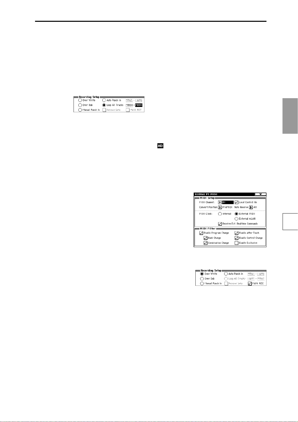
• Loop All Tracks
This method lets you continue recording as you add
musical data.
The specified region can be recorded repeatedly. This is
ideal when recording drum phrases, etc.
1 Use “T rack Select” to select the track that you want to
record.
2 Set the “Recording Mode” to Loop All Tracks.
If “Multi REC” is checked, it will not be possible to
select Loop All Tracks.
3 In “M (Loop Start Measure), “M (Loop End Mea-
sure)” specify the area that you wish to record.
For example if you specify M004–M008, recording will
occur repeatedly (as a loop) from measure 4 to measure
8.
4 In “Location,” specify a location several measures
earlier than the point at which you wish to begin
recording.
5 Press the SEQUENCER [REC/WRITE] key, and then
press the SEQUENCER [START/STOP] key.
Playback will begin. When you reach the starting location you specified in step 3, recording will begin. Play
the keyboard and operate controllers such as the joystick to record your performance.
When you reach the ending location you specified in
step 3, you will return to the starting location, and
continue recording.
The musical data that is loop-recorded will be added to
the previously-recorded data.
6 You can also erase specific data even while you con-
tinue loop recording.
If you press the SEQUENCER [REC/WRITE] key during loop recording, all musical will be removed from
the currently selected track as long as you continue
pressing the key.
By checking the “Remove Data” check box you can
erase only the specified data. During loop recording,
press the note that you wish to delete, and only the
data of that note number will be deleted from the key-
board as long as you continue pressing that note.
Similarly, bender data will be deleted as long as you
tilt the joystick in the X (horizontal) direction, and
after touch data will be deleted as long as you apply
pressure to the keyboard.
When you are once again ready to record musical data,
uncheck the “Remove Data” check box.
7 Press the SEQUENCER [START/STOP] key.
Playback will end, and you will return to the recording
start location that you specified in step 4.
If Loop All Tracks is selected, normal playback will be
looped as well.
• Multi (multitrack recording)
Multitrack recording allows you to simultaneously
record onto multiple tracks, each with a different channel. This method can be used with overwrite, overdub,
manual punch-in, and auto punch-in recording.
Using the arpeggiator to record multiple tracks
simultaneously
A multi-track performance using the arpeggiator function can be recorded using multi recording.
When simultaneously recording multiple tracks
using the RPPR function
You can use multitrack recording to simultaneously
record the playback of multiple tracks that are being
triggered by the RPPR function. For the procedure,
refer to “Realtime-recording an RPPR performance”
(☞p.94).
When simultaneously recording multiple tracks of
MIDI data from an external sequencer.
1 Make sure that the TRITON STUDIO’s MIDI IN and
the external sequencer’s MIDI OUT are connected by
a MIDI cable.
If they are not connected, turn off the power, make the
connection, and then turn the power back on again.
(☞PG p.258)
If the EXB-mLAN option is installed, MIDI data can
be received from an mLAN device. (☞PG p.141)
2 Set the MIDI Clock (Global P1: MIDI page “MIDI
Clock”) to External, so that TRITON STUDIO will
synchronize to the MIDI clock of the external
sequencer.
Make sure that “Receive Ext. Realtime Commands” is
checked.
3 Create a new song, and in the Sequencer P0: Play/
REC, Preference page, check the “Multi REC” check
box. Set the “Recording Mode” to Over Write.
4 Select the P0: Play/REC, Program T01–08/T09–16
page.
For the tracks that you are not recording, set “PLAY/
MUTE/REC” to PLAY or MUTE.
5 In P2: Trk Param, MIDI Ch page “MIDI Channel,”
specify the MIDI channel for each track.
Set the MIDI channel of each external sequencer track
to match the MIDI channel of each TRITON STUDIO
track. Data of the corresponding channel will be
recorded on each TRITON STUDIO track.
Make sure that “Status” is set either to INT or BTH.
6 Press the [LOCATE] key to set the location to
001:01.000.
7 Press the SEQUENCER [REC/WRITE] key to enter
recording-standby mode.
8 Start the external sequencer.
The TRITON STUDIO’sequencer will receive the MIDI
Start message transmitted by the external sequencer,
and will automatically begin recording.
Basic functions
Saving dataLoading dataProgram
settings
settings
Combination
songs
Producing
settings
Sampling
CD
Creating a
SMF
playback
System
settings
settings
Drum kit
settings
Arpeggiator
Effects
settings
Other
functions
85
Page 94
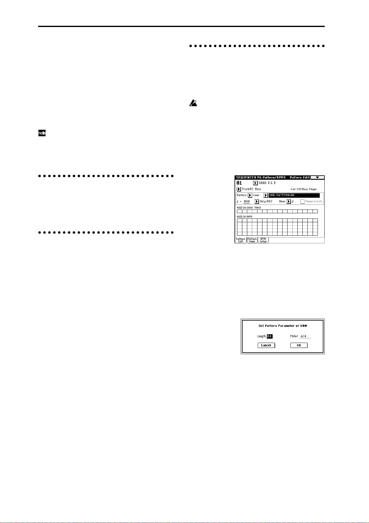
9 When the song ends, stop the external sequencer.
TRITON STUDIO’s sequencer will receive the MIDI
Stop message transmitted by the external sequencer,
and will automatically stop recording. You can also
press the SEQUENCER [START/STOP] key on TRITON STUDIO itself to stop recording.
0 Playback.
In the Global P1: MIDI page, set “MIDI Clock” to
Internal.
Set “Tempo Mode” to Auto.
When you press the SEQUENCER [START/STOP]
key, playback will begin.
If the correct sounds do not play immediately after
playback is started, you may be able to solve the
problem by using the page menu command “Event
Edit” (Sequencer P5: Track Edit) to edit the Program
Change data.
Step recording
This is a method of recording where you specify the note
timing, note length, and velocity etc. in the LCD screen,
and use the keyboard to input the pitches. (☞p.52)
Only note-on/off data can be recorded with this method.
Realtime-recording to a pattern
Here’s how you can use realtime recording to create a pattern. User patterns can be accessed by the RPPR function
in the same way as preset patterns, and can be copied to
or placed in a song. Playback data from a track can also be
copied to a pattern.
Before you begin recording a pattern, turn off the
memory protect setting in Global mode (☞p.57).
When realtime-recording a pattern, a pattern of the specified number of measures will playback repeatedly, allowing you to continue adding musical data to it.
1 Create a new song, and as described in “Preparations
for recording,” set the track to the program that will
be used by the pattern. (☞p.82)
2 Access the Sequencer P6: Pattern/RPPR, Pattern Edit
page.
Event Edit and Create Control Data
Note data is the only type of data that can be recorded in
step recording. However there are ways to record other
types of data, aside from the realtime mode. You can use
the Event Edit and Create Control Data functions.
Event Edit is intended as a way to edit previouslyrecorded data, but you can also use it to modify program
numbers or insert control changes.
Create Control Data is a function that lets you create and
insert controller data that changes smoothly between two
specified values over the specified length of time. This is
used to input bend, after touch, and control change data
etc.
3 Use “T rack Select” to select the track that you will use
to record the pattern.
The pattern will sound with the program and other settings of the selected track.
4 Set “Pattern (Pattern Bank)” to User, and set “Pattern
Select” to U00.
User patterns U00–U99 can be created for each song.
5 Select the page menu command “Pattern Parameter”.
A dialog box will appear.
6 Set the number of measures in the pattern to a
“Length” of 04 (four measures), and set “Meter” to a
time signature of 4/4. Press the OK button.
7 As necessary, set “Resolution” to apply realtime
quantization.
8 Begin realtime recording.
You can record in the same way as you did when
recording tracks with Loop All Tracks. (☞p.85)
Press the SEQUENCER [REC/WRITE] key, and then
press the SEQUENCER [START/STOP] key.
After the pre-count, pattern recording will begin. Play
the keyboard and operate the joystick and other controllers to record your performance.
When you reach the end of the pattern, the sequncer
will return to the beginning of the pattern and continue
recording. If you continue recording, the newly
recorded data will be added to the previously-recorded
data.
86
Page 95

9 If you want to delete specific data while you continue
pattern recording, you can press the SEQUENCER
[REC/WRITE] key or check the “Remove Data” check
box.
For details refer to step 6 of “Loop All Tracks”
(☞p.85).
0 Press the SEQUENCER [START/STOP] key to stop
recording.
If you made a mistake or decide to re-record, press the
SEQUENCER [START/STOP] key to stop recording,
and press the [COMPARE] key. Then begin the pattern
recording procedure again as in step 8.
Control data in pattern recording
T o recor d control data in a pattern, you should restore
the control data to its normal value within the pattern. If you fail to restore the normal value, unnecessary control data may remain in a “stuck” position
when you place the pattern in a song or use the RPPR
function to play the pattern. However, the following
control data will be automatically reset to the following values when the song or RPPR function finishes
playing the pattern, or when playback is halted.
Controller Reset value
Modulation 1 (CC#01) 00 (zero)
Modulation 2 (CC#02) 00 (zero)
Expression (CC#11) 127 (max)
Ribbon controller (CC#16) 64 (center)
Damper switch (CC#64) 00 (zero)
Sostenuto switch (CC#66) 00 (zero)
Soft switch (CC#67) 00 (zero)
EG sustain level (CC#70) 64 (center)
Resonance level (CC#71) 64 (center)
EG release time (CC#72) 64 (center)
EG attack time (CC#73) 64 (center)
Low pass filter cutoff (CC#74) 64 (center)
EG decay time (CC#75) 64 (center)
LFO1 speed (CC#76) 64 (center)
LFO1 depth (pitch) (CC#77) 64 (center)
LFO1 delay (CC#78) 64 (center)
Filter EG intensity (CC#79) 64 (center)
SW1 modulation (CC#80) 00 (zero)
SW2 modulation (CC#81) 00 (zero)
Channel after touch 00 (zero)
Pitch bender 00 (zero)
Using the arpeggiator for pattern recording
If the arpeggiator is set to operate for the track that is
selected for “Track Select,” you can turn on the ARPEGGIATOR [ON/OFF] key and record the performance of
the arpeggiator into the pattern.
For details on arpeggiator settings, refer to p.94 and PG
p.81.
Basic functions
Saving dataLoading dataProgram
settings
settings
Combination
songs
Producing
settings
Sampling
CD
Creating a
SMF
playback
System
settings
settings
Drum kit
87
settings
Arpeggiator
Effects
settings
Other
functions
Page 96

Song editing methods
A variety of editing operations can be performed on a
song. Here we will give some examples of how you can
use various editing operations on the song you created in
“Producing a song” (☞p.49), to prepare for creating a cue
list as described in the next section.
Load the SEQ_DM1.SNG file that you saved on p.54.
For the loading procedure, refer to p.63. In the explanations that follow, we will assume that the song you
created has been loaded into song S000. After loading
the song, press the [SEQ] key to enter Sequencer
mode.
1. Copying a song
Here’s how to copy a song. This is convenient when you
want to create different variations based on a song.
1 Create a new song.
Access the Sequencer P0: Play/REC, Program T01–08
page.
Choose “Song Select,” use the numeric keys to input
the song number that you want to newly create, and
press the [ENTER] key. (For example, press the [1] key
and then the [ENTER] key.)
A dialog box will appear.
3 As described in steps 1 and 2, create one more new
song (S002), and copy song S000 to it.
2. Naming a song
Here’s how to assign a name to a song you created.
1 Choose “Song Select,” to select a song.
For this example, select song 002.
2 In the Sequencer P0: Play/REC, Program T01–08 page,
select the page menu command “Rename Song.”
A dialog box will appear. Press the text edit button to
access the text dialog box.
Press the Clear button, and input CHORUS (☞p.40).
When you are finished inputting the name, press the
OK button.
Press the OK button once again to execute the Rename
operation.
3 As described in steps 1 and 2, assign a name of
INTRO to S000, and VERSE to S001.
Decide on the number of measures, input the number
in “Set Length,” and press the OK button.
A new song will be created. Next we will copy the song
settings and playback data of another song into this
newly created song.
2 Select the page menu command “Copy From Song.”
3. Setting the number of measures in
the song
Here’s how to specify the number of measures in the song.
By default, this is set to 64 measures. If you realtimerecord for more measures than this, the song length will
be the amount of measures you have recorded.
1 Select song S000: INTRO.
2 Select the Sequencer P5: Track Edit, Track Edit page.
In the P5: Track Edit page, press the [MENU] key to
access the Jump page. Press the P5: Track Edit.
3 Access the page menu.
This contains various commands for editing tracks and
measures.
Press the “Set Song Length.”
A dialog box will appear. Select the song that you want
to copy (i.e., the copy source). If you select All, all song
settings and playback data will be copied from that
song. If you select Without Track/Pattern Events, settings other than Play Loop and RPPR will be copied.
For this example, select All.
Press the OK button to execute the copy.
88
Page 97

A dialog box will appear.
Input the number of measures for the song. For this
example, select 008 (8 measures) and press the OK button.
The performance data from measures 1–8 will remain,
and the data of subsequent measures will be deleted.
When you press the SEQUENCER [START/STOP] key
to play the song, playback will stop at the end of the
8th measure.
If you are using Track Play Loop, check whether the
measures specified for “Loop Start Measure” and
“Loop End Measure” would be deleted. If they
would be deleted, use “Move Measure” (☞PG p.72)
etc. to move the data into the playback area before
you execute this operation.
4 Mute tracks.
Press the [EXIT] key to select P0: Play/REC, and access
the Program T01–08/T09–16 page.
Mute all tracks other than tracks 3 and 4. When you
play back, you will hear only the electric piano and
guitar performances.
4. Changing the key (transposing/ modulating)
Here’s how to change the key of a song.
1 Select song S002: CHORUS.
2 Select the Sequencer P5: Track Edit page.
3 Use “Track Select” to select T02 as the track whose
pitch will be changed.
4 Specify the measures for which the key will be
changed.
Select “From Measure,” and use the V ALUE contr ollers
to set this to 001. Next select “To End of Measure,” and
specify 008.
5 Select the page menu command “Shift/Erase Note.”
A dialog box will appear. If you did not specify the
range of measures in step 4, set “From Measure”–“To
Measure” to specify the range that will be edited.
Turn on the Replace radio button, and set “Shift
Note” to +003. (☞PG p.74)
Basic functions
Saving dataLoading dataProgram
settings
settings
Combination
5 As described in steps 1–4, set song S001: VERSE to
008 (8 measures), making it an eight measure song.
Then mute all tracks other than tracks 1–3. When you
play back, you will hear only the drums, bass, and electric piano.
6 As described in steps 1–4, set song S002: CHORUS
to 008 (8 measures), making it an eight measure song.
Press the OK button. The pitch of track 2 will be raised
three semitones.
6 Use the same procedure to raise the pitch three semi-
tones for each track on which performance data is
recorded. However, do not change the key of track 1
which uses a drum kit.
If you change the key of a track that is using a drum
kit, the relationship between the notes and the instruments of the drum kit will be shifted, and the
sequence will not play the correct rhythm instruments.
songs
Producing
settings
Sampling
CD
Creating a
SMF
playback
System
settings
settings
Drum kit
settings
Arpeggiator
Effects
settings
89
Other
functions
Page 98

About editing
Song editing
In addition to copying and renaming a song, other operations such as Delete can be performed from the Utility
menu commands in pages such as Sequencer P0: Play/
REC (☞PG p.52).
Track editing
Event Editing allows you to edit or insert data in a
recorded track. In addition, commands such as Create
Control Data (which lets you insert pitch bend, aftertouch,
or control change data) and other commands for deleting,
copying, inserting, or moving tracks can be accessed from
the page menu command in the Sequencer P5: Track Edit
(☞PG p.68).
Pattern editing
Using the page menu commands of the Sequencer P6: Pattern/RPPR, Pattern page, you can use event editing to
modify the recorded data or insert new data, and execute
commands to delete, copy , or bounce patterns (☞PG p.77).
Creating and playing a Cue List
A cue list allows you to play multiple songs in succession.
For example you can create a separate song for each portion (introduction, melody A, melody B, chorus, and ending) of a composition, and use the cue list to specify the
order of each portion and the number of times that it will
be repeated to complete the song. If you want to change
the structure of the song, the cue list lets you do so in an
efficient way.
You can also use this as a jukebox function that will playback completed songs in the order you specify.
Cue List
Step
01
S000: Intro
02
S001: A
S002: B
03
S003: Chorus
04
S001: A
05
06
S002: B
07
S003: Chorus
08
S001: A (Solo)
S003: Chorus
09
S004: Ending
10
Each unit in a cue list is called a “step,” and each step contains a song number and the number of repeats.
Here we will use a cue list to combine the previously-created songs S000: INTRO, S001: VERSE, and S002: CHORUS.
1 Select Sequencer P1: Cue List.
With the default settings, song S000 will be selected for
“Step” 01, and End will be selected for “Step” 02.
Song
Repeat
02
02
01
02
02
01
02
01
03
02
Intro
Intro A A B Chorus
AA
Chorus
A(Solo) Chorus Chorus Chorus
B Chorus
Ending
Chorus
Ending
90
2 Add a song to the Step area.
Select the “Song” for Step 02, and press the Insert button. A song will be added to step 02. Use the VALUE
controller to select S001: VERSE.
In the same way, select the Step 03 “Song,” and press
the Insert button to add a song to Step 03. Set this to
S002: CHORUS.
If you press Cut button, the selected step will be
deleted. If you press the Insert button key, the deleted
step will be inserted.
If you press the Copy button, the selected step will be
copied. If you press the Insert button, the copied step
will be inserted.
3 Set the last step to End.
If you set this to Continue to Step01, the cue list will
play back repeatedly.
Page 99

4 In “Repeat,” specify the number of times that the
song for that step will be repeated. For this example,
set Step 02 S001: VERSE to 02.
5 Specify whether effect settings will also be switched
when the song at each step is played back. If you
want to effect settings to change, check the “FX”
check box.
For this example, check the “FX” check box for Step 01,
which loads the effects.
6 To play back at the tempo that was specified for each
song, set “Tempo Mode” to Auto.
If this is set to Manu (Manual), playback will use the
tempo specified by “ =”.
7 When you press the SEQUENCER [START/STOP]
key, playback will begin from the step that is specified as the “Current Step.”
or MIDI control changes such as Effect Control to control
the effects within the cue list, for example applying reverb
more deeply on certain songs, or raising the LFO speed
for a specific song. We r ecommend this method if you will
be using a cue list to construct the song.
When you execute the page menu command “Convert to
Song”, the effect settings of the “Step” 01 song will be
specified for the song that results from the conversion.
Even if “FX” is not checked, there may be cases in which a
time lag in the transition between songs, depending on
the musical data of the song. Also, there may be cases in
which the musical data is not played at the correct timing
at the transition between songs. If this occurs, you can edit
the musical data of the song, or convert the cue list to a
song for playback. If you use “Convert to Song” to convert the cue list to a song, there will be no time lag during
playback at the transition between songs, and the musical
data will be played at the correct timing.
Creating multiple songs for use in a cue list
If you want to create multiple songs for use in a cue list, it
is a good idea to make the various necessary settings (program and other settings for each track, effect settings, etc.)
for one song (e.g., S000), and then use the page menu command “Copy From Song” in SEQ 1.1 etc. to copy it to
other songs so that the settings will be consistent.
Basic functions
Saving dataLoading dataProgram
settings
•“Step”: The arrow will indicate the currently playing
step. indicates the currently selected “Step.” If you
set “Current Step” while stopped, the display will
change.
•“M****”: Indicates the starting measure of that step.
•“Meter”: Indicates the currently-playing time
signature. This cannot be changed.
• The name of a cue list can be specified by the
“Rename Cue List” page menu command.
• When you play the keyboard, the program of the track
selected by “Track Select” will sound. If a different
program is selected for each song, the program
specified for the currently playing song will sound.
What to do when playing back a cue list and the
songs do not transition smoothly
Depending on the effect settings, a certain amount of time
may be required for the effects to be switched. If this
occurs, the playback will not be smoothly connected from
song to song.
To ensure a smooth transition from song to song, check
“FX” for “Step” 01. Do not check “FX” for the remaining
steps. This way, the effect settings will be made before
playback begins, and there will be no time lag when cue
list playback is started or when switching from song to
song. Although it will not be possible to change effect
types within the cue list, you can use dynamic modulation
After your cue list is finished and you convert it into a
song, the track settings (program, pan, volume, etc.)
of each step will be converted into playback data and
will be reproduced, but if the MIDI channel settingsfrom song to song do not match, it may not be possible to convert the playback state of the cue list into a
song.
Using a foot switch to switch the Step
You can use a foot switch to switch the Step.
If you set “Repeat” to FS, a foot switch connected to the
ASSIGNABLE SWITCH jack will control the timing at
which the song stops repeating. Set “Foot Switch Assign”
(Global P2: Controller page) to Cue Repeat Control.
settings
Combination
songs
Producing
settings
Sampling
CD
Creating a
SMF
playback
System
settings
settings
Drum kit
settings
Arpeggiator
Effects
settings
Other
functions
91
Page 100

Converting a song
Although it is not possible to record additional material
onto tracks in a cue list, you can convert a cue list to a
song, and then record solos etc. on vacant tracks. You will
also need to convert a cue list to a song if you wish to save
it on a floppy disk etc. as SMF data.
1 Select the page menu command “Convert to Song”.
A dialog box will appear.
2 In “To Song,” specify the destination song number
for the converted data.
The cue list name will automatically be assigned as the
song name of the converted data. (For details and cautions regarding “Convert to Song,” refer to PG p.61.)
If you select a new song as the conversion destination,
it is not necessary to specify “Set Length” in the dialog
box that appears. The number of measures in the converted song will be used. Press the OK button, and the
Convert Cue List dialog box will appear.
3 Press the OK button.
The cue list will be converted into a song. Access the
P0: Play/REC page, select the song number that you
specified as the conversion destination, and check the
results.
Creating and recording RPPR (Realtime Pattern Play/Record)
This section explains how to assign a pattern to RPPR,
and how to play and record. (“Playing with the RPPR
(Realtime Pattern Play/Recording) function” ☞p.33)
Creating RPPR data
1 Create a new song. (☞p.88)
2 Specify the program for each track.
For this example we will use a template song. Use the
Utility menu command “Load Template Song” to load
P14: Hip Hop/Rap. It is not necessary to copy the patterns. (☞p.49)
3 Select the Sequencer P6: Pattern/RPPR, RPPR Setup
page.
In this page, the RPPR function is automatically turned
on.
4 Use “KEY” to select the key to which the pattern will
be assigned.
Select C#2. This can also be selected by holding down
the [ENTER] key and playing a note.
C2 and lower keys are used to stop playback, and cannot be assigned.
5 Check the “Assign” check box.
6 Set Pattern Bank to the Preset pattern type, and set
“Pattern Select” to pattern P121: HipHop 1/HipHop.
7 Set “Track” to Track01: Drums.
The selected pattern will be played according to the
settings (program, etc.) of the track you select here.
8 Assign patterns to other keys.
For “KEY,” press the [ ] key to select D2.
Press the REVERT button.
The settings for “Assign,” “Pattern (Pattern Bank),”
“Pattern Select,” and “Track” will be set to the values
that were specified earlier (in steps 5–7).
Choose “Pattern Select,” and press the [ ] key to
select P122: HipHop 2/HipHop.
92
 Loading...