

Page 1

5E
Page 2
IMPORTANT SAFETY INSTRUCTIONS
WARNING
— When using electrical products, basic precautions should be followed, including the following:
1. Read all the instructions before using the
product.
2. Do not use this product near water — for
example, near a bathtub, washbowl, kitchen sink,
in a wet basement, or near a swimming pool, or
the like.
3. This product should be used only with the cart or
stand that is recommended by the manufacturer.
4. This product, either alone or in combination with
an amplifier and headphones or speakers, may
cause permanent hearing loss. Do not operate
for a long period of time at a high volume level or
at a level that is uncomfortable. If you experience
any hearing loss or ringing in the ears, you
should consult an audiologist.
5. The product should be located so that its location
or position does not interfere with its proper
ventilation.
6. The product should be located away from heat
sources such as radiators, heat registers, or
other products that produce heat.
7. The product should be connected to a power
supply of the type described in the operating
instructions or as marked on the product.
8. The power-supply cord of the product should be
unplugged from the outlet when left unused for a
long period of time.
9. Care should be taken so that objects do not fall
and liquids are not spilled into the enclosure
through openings.
10.The product should be serviced by qualified
personnel when:
A. The power-supply cord or the plug has been
damaged; or
B. Objects have fallen, or liquid has been spilled
into the product; or
C. The product has been exposed to rain; or
D. The product does not appear to operate
normally or exhibits a marked change in
performance; or
E. The product has been dropped, or the
enclosure damaged.
11.Do not attempt to service the product beyond
that described in the user-maintenance
instructions. All other servicing should be
referred to qualified service personnel.
SA VE THESE INSTRUCTIONS
CAUTION
RISK OF ELECTRIC SHOCK
DO NOT OPEN
CAUTION: TO REDUCE THE RISK OF
ELECTRIC SHOCK, DO NOT REMOVE
COVER (OR BACK). NO USER-SERVICEABLE
PARTS INSIDE. REFER SERVICING TO
QUALIFIED SERVICE PERSONNEL.
GROUNDING INSTRUCTIONS
This product must be grounded (earthed). If it should malfunction or breakdown,
grounding a path of least resistance for electric current to reduce the risk of
electric shock. This product is equipped with a cord having an
equipment-grounding conductor and a grounding plug. The plug must be
plugged into an appropriate outlet that is properly installed and grounded in
accordance with the local codes and ordinances.
DANGER
result in a risk of electric shock. Check with a qualified electrician or serviceman
if you are in doubt as to whether the product is properly grounded. Do not modify
the plug provided with the product – if it will not fit the outlet, have a proper outlet
fitted.
– Improper connection of the equipment-grounding conductor can
The lightning flash with the arrowhead symbol
within an equilateral triangle, is intended to alert
the user to the presence of uninsulated
“dangerous voltage” within the product’s
enclosure that may be of sufficient magnitude to
constitute a risk of electric shock.
The exclamation point within an equilateral
triangle is intended to alert the user to the
presence of important operating and
maintenance (servicing) instructions in the
literature accompanying the product.
i
Page 3

THE FCC REGULATION WARNING
This equipment has been tested and found to comply with the limits for a Class B digital device, pursuant to
Part 15 of the FCC Rules. These limits are designed to provide reasonable protection against harmful
interference in a residential installation. This equipment generates, uses, and can radiate radio frequency
energy and, if not installed and used in accordance with the instructions, may cause harmful interference to
radio communications. However, there is no guarantee that interference will not occur in a particular
installation. If this equipment does cause harmful interference to radio or television reception, which can be
determined by turning the equipment off and on, the user is encouraged to try to correct the interference by
one or more of the following measures:
• Reorient or relocate the receiving antenna.
• Increase the separation between the equipment and receiver.
• Connect the equipment into an outlet on a circuit different from that to which the receiver is connected.
• Consult the dealer or an experienced radio/TV technician for help.
Unauthorized changes or modification to this system can void the user’s authority to operate this equipment.
CE mark for European Harmonized Standards
CE mark which is attached to our company’s products of AC mains operated apparatus until December 31,
1996 means it conforms to EMC Directive (89/336/EEC) and CE mark Directive (93/68/EEC).
And, CE mark which is attached after January 1, 1997 means it conforms to EMC Directive (89/336/EEC), CE
mark Directive (93/68/EEC) and Low Voltage Directive (73/23/EEC).
Also, CE mark which is attached to our company’s products of Battery operated apparatus means it conf orms
to EMC Directive (89/336/EEC) and CE mark Directive (93/68/EEC).
IMPORTANT NOTICE FOR THE UNITED KINGDOM
WARNING—THIS APPARATUS MUST BE EARTHED
As the colours of the wires in the mains lead of this apparatus may not correspond with the coloured markings
identifying the terminals in your plug,proceed as follows:
• the wire which is coloured green and yellow must be connected to the terminal in the plug which is marked
with the letter E or by the earth symbol , or coloured green or green and yellow.
• the wire which is coloured blue must be connected to the terminal which is marked with the letter N or
coloured black.
• the wire which is coloured brown must be connected to the terminal which is marked with the letter L or
coloured red.
Back-up Battery
The TRINITY uses a back-up battery to prevent memory loss when the po wer is turned off. If the display
shows “Battery Low”, the battery should be replaced. Consult the nearest K org Service Center or dealer .
TRINITY Series Precaution
Data in memory may sometimes be lost due to incorrect user action. Be sure to save important data to
floppy disk.
Korg will not be responsible for damages caused by data loss.
Trademarks
MS-DOS is a registered trademark of Microsoft Corporation.
All trademarks or registered trademarks are the property of their respective holders.
ii
Page 4

About the TRINITY’s manuals
About the TRINITY’s manuals
How the TRINITY’s manuals are organized and how to
use them
This page explains the contents of each manual, and how to use them. First you should read the
Basic Guide
These manuals assume that you have a basic knowledge of synthesizers and MIDI.
* In the TRINITY’s manuals, parameter names, values are merely examples and may not always match the
Basic Guide
“
STEP 1
tion, and how each mode operates.
“
STEP 2
and convenient performance functions).
“
STEP 3
Other information on troubleshooting and MIDI is also provided.
☛
After you finish reading
operation. To take full advantage of the TRINITY, you will need to thoroughly understand the
contents of the B
to learn for yourself how the sounds change.
, and learn the basic ideas and procedures that you need to know.
The
TRINITY’s manuals
V3 proX
. If the Solo synthesizer option is installed in your instrument, read any references to
“bank M” as “bank S.”
actual display you are working on.
” explains each item on the front and rear panels, how to make connections, basic opera-
” explains the basics of playing the
” explains the basics you need to know before editing your own sounds.
asic Guide
discusses the
STEP 2
, and then get plenty of hands-on experience, operating the TRINITY
TRINITY, TRINITY V3, TRINITY V3 pro
, read
TRINITY
STEP 3
(selecting sounds, playing the demo songs,
as necessary. The
Basic Guide
, and
explains the basics of
TRINITY
Parameter Guide
The Parameter Guide explains the operation, settings, and points that you need to be aware of for
each parameter, organized by the tab pages of each mode.
☛
Refer to this guide when an unfamiliar parameter appears, or when you want to learn about the
functions of the
TRINITY series
in more detail.
Effect Guide
For each of the effects, this guidebook explains the parameter settings and points that you need to
be aware of.
☛
Refer to the Effect Guide when an unfamiliar parameter appears, or when you want to learn about
the function of the selected effect in more detail.
MOSS-TRI DSP Synthesizer Guide
This explains the setting and operation of the
TRINITY V3 pro
and
TRINITY V3 proX
bank M
, organized by each tab page.
program parameters on the
Solo Synthesizer Guide
This explains the setting and operation of the
TRINITY V3 pro
and
TRINITY V3 proX
bank S
, organized by each tab page.
program parameters on the
Voice Name List, Voice Name List for V3
This contains name lists of the preloaded (factory preset) combinations, programs, multi-samples,
and drum samples.
☛
Refer to these lists when you wish to see a list of the preloaded sounds.
TRINITY V3,
TRINITY V3,
iii
Page 5
How to use this Parameter Guide
How to use this Parameter Guide
The explanatory material in this manual is formatted as follows.
(Example)
• Other symbols used in this manual
This symbol appears at the left of explanatory material related to MIDI.
This mark appears at the right of the parameter name for parameters which can be
selected as a source for Alternate Modulation.
• In this manual, “CC#” is an abbreviation of Control Change Number.
• Numbers related to MIDI messages in square brackets [ ] are in hexadecimal notation.
iv
Page 6

Table of Contents
Table of Contents
1. Program Play mode
Program Play P1. . . . . . . . . . . . . . . . . . . . . . . . . . . . . . . . . . . . . . . . . . . . . . . . . . . . . . . . . .1
1–1: Program Play. . . . . . . . . . . . . . . . . . . . . . . . . . . . . . . . . . . . . . . . . . . . . . . . . . . . . .1
2. Program Edit mode
Program Edit P1 . . . . . . . . . . . . . . . . . . . . . . . . . . . . . . . . . . . . . . . . . . . . . . . . . . . . . . . . . .5
1–1: Prog Basic (Program Basic) . . . . . . . . . . . . . . . . . . . . . . . . . . . . . . . . . . . . . . . . . .5
1–2: OSC Basic (Oscillator Basic) . . . . . . . . . . . . . . . . . . . . . . . . . . . . . . . . . . . . . . . . .9
Program Edit P2 . . . . . . . . . . . . . . . . . . . . . . . . . . . . . . . . . . . . . . . . . . . . . . . . . . . . . . . . .12
2–1: OSC1 Pitch Mod (Oscillator Pitch Modulation). . . . . . . . . . . . . . . . . . . . . . . .12
2–2: OSC1 LFO (Oscillator 1 LFO) . . . . . . . . . . . . . . . . . . . . . . . . . . . . . . . . . . . . . . .16
2–3: OSC2 Pitch Mod (Oscillator 2 Pitch Modulation) . . . . . . . . . . . . . . . . . . . . . .20
2–4: OSC2 LFO (Oscillator 2 LFO) . . . . . . . . . . . . . . . . . . . . . . . . . . . . . . . . . . . . . . .20
2–5: OSC EG (Oscillator Envelope Generator) . . . . . . . . . . . . . . . . . . . . . . . . . . . .21
Program Edit P3 . . . . . . . . . . . . . . . . . . . . . . . . . . . . . . . . . . . . . . . . . . . . . . . . . . . . . . . . .24
3–1: Filter 1 A/B (Filter 1A/Filter 1B) . . . . . . . . . . . . . . . . . . . . . . . . . . . . . . . . . . . .24
3–2: Filter 1 Mod (Filter 1 Modulation) . . . . . . . . . . . . . . . . . . . . . . . . . . . . . . . . . . .28
3–3: Filter 2 A/B (Filter 2A/Filter 2B) . . . . . . . . . . . . . . . . . . . . . . . . . . . . . . . . . . . .32
3–4: Filter 2 Mod (Filter 2 Modulation) . . . . . . . . . . . . . . . . . . . . . . . . . . . . . . . . . . .32
Program Edit P4 . . . . . . . . . . . . . . . . . . . . . . . . . . . . . . . . . . . . . . . . . . . . . . . . . . . . . . . . .33
4–1: Filter 1 EG . . . . . . . . . . . . . . . . . . . . . . . . . . . . . . . . . . . . . . . . . . . . . . . . . . . . . . .33
4–2: Filter 1 LFO . . . . . . . . . . . . . . . . . . . . . . . . . . . . . . . . . . . . . . . . . . . . . . . . . . . . . .37
4–3: Filter 2 EG . . . . . . . . . . . . . . . . . . . . . . . . . . . . . . . . . . . . . . . . . . . . . . . . . . . . . . .39
4–4: Filter 2 LFO . . . . . . . . . . . . . . . . . . . . . . . . . . . . . . . . . . . . . . . . . . . . . . . . . . . . . .39
Program Edit P5 . . . . . . . . . . . . . . . . . . . . . . . . . . . . . . . . . . . . . . . . . . . . . . . . . . . . . . . . .40
5–1: Amp 1 Mod (Amplifier 1 Modulation) . . . . . . . . . . . . . . . . . . . . . . . . . . . . . . .40
5–2: Amp 1 EG (Amplifier 1 EG) . . . . . . . . . . . . . . . . . . . . . . . . . . . . . . . . . . . . . . . .44
5–3: Amp 2 Mod (Amplifier 2 Modulation) . . . . . . . . . . . . . . . . . . . . . . . . . . . . . . .47
5–4: Amp 2 EG (Amplifier 2 EG) . . . . . . . . . . . . . . . . . . . . . . . . . . . . . . . . . . . . . . . .47
Program Edit P7 . . . . . . . . . . . . . . . . . . . . . . . . . . . . . . . . . . . . . . . . . . . . . . . . . . . . . . . . .48
7–1: Insert Effects . . . . . . . . . . . . . . . . . . . . . . . . . . . . . . . . . . . . . . . . . . . . . . . . . . . . .48
7–2: Edit E1 (Edit Insert Effect 1) . . . . . . . . . . . . . . . . . . . . . . . . . . . . . . . . . . . . . . . .50
7–3: Edit E2 (Edit Insert Effect 2) . . . . . . . . . . . . . . . . . . . . . . . . . . . . . . . . . . . . . . . .50
7–4: Edit E3 (Edit Insert Effect 3) . . . . . . . . . . . . . . . . . . . . . . . . . . . . . . . . . . . . . . . .50
7–5: Edit E4 (Edit Insert Effect 4) . . . . . . . . . . . . . . . . . . . . . . . . . . . . . . . . . . . . . . . .50
Program Edit P8 . . . . . . . . . . . . . . . . . . . . . . . . . . . . . . . . . . . . . . . . . . . . . . . . . . . . . . . . .51
8–1: Master Effects . . . . . . . . . . . . . . . . . . . . . . . . . . . . . . . . . . . . . . . . . . . . . . . . . . . .51
8–2: Edit E1 (Edit Master Effect 1 [Modulation]) . . . . . . . . . . . . . . . . . . . . . . . . . . .53
8–3: Edit E2 (Edit Master Effect 2 [Reverb/Delay]). . . . . . . . . . . . . . . . . . . . . . . . .53
. . . . . . . . . . . . . . . . . . . . . . . . . . . . . . . . . . . . . . . . . . . . . . . . . . . .1
. . . . . . . . . . . . . . . . . . . . . . . . . . . . . . . . . . . . . . . . . . . . . . . . . . . . .5
3. Combination Play mode
Combination Play P1 . . . . . . . . . . . . . . . . . . . . . . . . . . . . . . . . . . . . . . . . . . . . . . . . . . . . .55
1–1: Combination Play. . . . . . . . . . . . . . . . . . . . . . . . . . . . . . . . . . . . . . . . . . . . . . . . .55
4. Combination Edit mode
Combination Edit P1 . . . . . . . . . . . . . . . . . . . . . . . . . . . . . . . . . . . . . . . . . . . . . . . . . . . . .57
1–1: Timb Param1 (Timbre Parameter 1) . . . . . . . . . . . . . . . . . . . . . . . . . . . . . . . . .57
1–2: Timb Param2 (Timbre Parameter 2) . . . . . . . . . . . . . . . . . . . . . . . . . . . . . . . . .59
1–3: Timb Param3 (Timbre Parameter 3) . . . . . . . . . . . . . . . . . . . . . . . . . . . . . . . . .60
Combination Edit P2 . . . . . . . . . . . . . . . . . . . . . . . . . . . . . . . . . . . . . . . . . . . . . . . . . . . . .61
2–1: Pitch . . . . . . . . . . . . . . . . . . . . . . . . . . . . . . . . . . . . . . . . . . . . . . . . . . . . . . . . . . . .61
Combination Edit P3 . . . . . . . . . . . . . . . . . . . . . . . . . . . . . . . . . . . . . . . . . . . . . . . . . . . . .63
3–1: Key Zone . . . . . . . . . . . . . . . . . . . . . . . . . . . . . . . . . . . . . . . . . . . . . . . . . . . . . . . .63
3–2: Velocity Zone . . . . . . . . . . . . . . . . . . . . . . . . . . . . . . . . . . . . . . . . . . . . . . . . . . . .65
Combination Edit P4 . . . . . . . . . . . . . . . . . . . . . . . . . . . . . . . . . . . . . . . . . . . . . . . . . . . . .67
4–1: Filter . . . . . . . . . . . . . . . . . . . . . . . . . . . . . . . . . . . . . . . . . . . . . . . . . . . . . . . . . . . .67
Combination P7 . . . . . . . . . . . . . . . . . . . . . . . . . . . . . . . . . . . . . . . . . . . . . . . . . . . . . . . . .69
v
. . . . . . . . . . . . . . . . . . . . . . . . . . . . . . . . . . . . . . . . . . . . . . .55
. . . . . . . . . . . . . . . . . . . . . . . . . . . . . . . . . . . . . . . . . . . . . . . .57
Page 7

Table of Contents
7–1: Effect Grouping . . . . . . . . . . . . . . . . . . . . . . . . . . . . . . . . . . . . . . . . . . . . . . . . . .69
7–2: Insert Effects (Timbre 1–8 Effects) . . . . . . . . . . . . . . . . . . . . . . . . . . . . . . . . . . .71
7–3: T1 E1 (Timbre 1–8 Edit Insert Effect 1) . . . . . . . . . . . . . . . . . . . . . . . . . . . . . . .73
7–4: T1 E2 (Timbre 1–8 Edit Insert Effect 2) . . . . . . . . . . . . . . . . . . . . . . . . . . . . . . .73
7–5: T1 E3 (Timbre 1–8 Edit Insert Effect 3) . . . . . . . . . . . . . . . . . . . . . . . . . . . . . . .73
7–6: T1 E4 (Timbre 1–8 Edit Insert Effect 4) . . . . . . . . . . . . . . . . . . . . . . . . . . . . . . .73
Combination Edit P8 . . . . . . . . . . . . . . . . . . . . . . . . . . . . . . . . . . . . . . . . . . . . . . . . . . . . .74
8–1: Master Effects . . . . . . . . . . . . . . . . . . . . . . . . . . . . . . . . . . . . . . . . . . . . . . . . . . . .74
8–2: Edit E1 (Edit Master Effect 1 [Modulation]). . . . . . . . . . . . . . . . . . . . . . . . . . .76
8–3: Edit E2 (Edit Master Effect 2 [Reverb/Delay]). . . . . . . . . . . . . . . . . . . . . . . . .76
5. Sequencer mode
Sequencer P1. . . . . . . . . . . . . . . . . . . . . . . . . . . . . . . . . . . . . . . . . . . . . . . . . . . . . . . . . . . .77
1–1: Track Play/Rec (Track 1–8) . . . . . . . . . . . . . . . . . . . . . . . . . . . . . . . . . . . . . . . .77
1–2: Track Play/Rec (Track 9–16) . . . . . . . . . . . . . . . . . . . . . . . . . . . . . . . . . . . . . . .77
1–3: Mixer (Track 1–8) . . . . . . . . . . . . . . . . . . . . . . . . . . . . . . . . . . . . . . . . . . . . . . . . .83
1–4: Mixer (Track 9–16) . . . . . . . . . . . . . . . . . . . . . . . . . . . . . . . . . . . . . . . . . . . . . . . .83
1–5: for Audio Track . . . . . . . . . . . . . . . . . . . . . . . . . . . . . . . . . . . . . . . . . . . . . . . . . .85
1–6: for Audio Track . . . . . . . . . . . . . . . . . . . . . . . . . . . . . . . . . . . . . . . . . . . . . . . . . .85
1–7: Preference . . . . . . . . . . . . . . . . . . . . . . . . . . . . . . . . . . . . . . . . . . . . . . . . . . . . . . .86
Sequencer P2. . . . . . . . . . . . . . . . . . . . . . . . . . . . . . . . . . . . . . . . . . . . . . . . . . . . . . . . . . . .89
2–1: Track Parameter (Track 1–8). . . . . . . . . . . . . . . . . . . . . . . . . . . . . . . . . . . . . . . .89
2–2: Track Parameter (Track 9–16). . . . . . . . . . . . . . . . . . . . . . . . . . . . . . . . . . . . . . .89
2–3: Pitch (Track 1–8). . . . . . . . . . . . . . . . . . . . . . . . . . . . . . . . . . . . . . . . . . . . . . . . . .92
2–4: Pitch (Track 9–16). . . . . . . . . . . . . . . . . . . . . . . . . . . . . . . . . . . . . . . . . . . . . . . . .92
Sequencer P3. . . . . . . . . . . . . . . . . . . . . . . . . . . . . . . . . . . . . . . . . . . . . . . . . . . . . . . . . . . .94
3–1: Key Zone (Track 1–8). . . . . . . . . . . . . . . . . . . . . . . . . . . . . . . . . . . . . . . . . . . . . .94
3–2: Key Zone (Track 9–16). . . . . . . . . . . . . . . . . . . . . . . . . . . . . . . . . . . . . . . . . . . . .94
3–3: Velocity Zone (Track 1–8) . . . . . . . . . . . . . . . . . . . . . . . . . . . . . . . . . . . . . . . . . .96
3–4: Velocity Zone (Track 9–16) . . . . . . . . . . . . . . . . . . . . . . . . . . . . . . . . . . . . . . . . .96
Sequencer P4. . . . . . . . . . . . . . . . . . . . . . . . . . . . . . . . . . . . . . . . . . . . . . . . . . . . . . . . . . . .98
4–1: Filter (Track 1–8). . . . . . . . . . . . . . . . . . . . . . . . . . . . . . . . . . . . . . . . . . . . . . . . . .98
4–2: Filter (Track 9–16). . . . . . . . . . . . . . . . . . . . . . . . . . . . . . . . . . . . . . . . . . . . . . . . .98
Sequencer P5. . . . . . . . . . . . . . . . . . . . . . . . . . . . . . . . . . . . . . . . . . . . . . . . . . . . . . . . . . .101
5–1: Track Edit . . . . . . . . . . . . . . . . . . . . . . . . . . . . . . . . . . . . . . . . . . . . . . . . . . . . . .101
5–2: Track Name. . . . . . . . . . . . . . . . . . . . . . . . . . . . . . . . . . . . . . . . . . . . . . . . . . . . .114
Sequencer P6. . . . . . . . . . . . . . . . . . . . . . . . . . . . . . . . . . . . . . . . . . . . . . . . . . . . . . . . . . .116
6–1: Pattern Edit . . . . . . . . . . . . . . . . . . . . . . . . . . . . . . . . . . . . . . . . . . . . . . . . . . . . .116
6–2: Pattern Name . . . . . . . . . . . . . . . . . . . . . . . . . . . . . . . . . . . . . . . . . . . . . . . . . . .120
Sequencer P7. . . . . . . . . . . . . . . . . . . . . . . . . . . . . . . . . . . . . . . . . . . . . . . . . . . . . . . . . . .122
7–1: Effect Grouping (Track 1–8) . . . . . . . . . . . . . . . . . . . . . . . . . . . . . . . . . . . . . . .122
7–2: Effect Grouping (Track 9–16) . . . . . . . . . . . . . . . . . . . . . . . . . . . . . . . . . . . . . .122
7–3: Insert Effects (Track 1–16 Effects) . . . . . . . . . . . . . . . . . . . . . . . . . . . . . . . . . .123
7–4: T1 E1 (Track 1–16 Edit Insert Effect 1). . . . . . . . . . . . . . . . . . . . . . . . . . . . . . .125
7–5: T1 E2 (Track 1–16 Edit Insert Effect 2). . . . . . . . . . . . . . . . . . . . . . . . . . . . . . .125
7–6: T1 E3 (Track 1–16 Edit Insert Effect 3). . . . . . . . . . . . . . . . . . . . . . . . . . . . . . .125
7–7: T1 E4 (Track 1–16 Edit Insert Effect 4). . . . . . . . . . . . . . . . . . . . . . . . . . . . . . .125
Sequencer P8. . . . . . . . . . . . . . . . . . . . . . . . . . . . . . . . . . . . . . . . . . . . . . . . . . . . . . . . . . .126
8–1: Master Effects . . . . . . . . . . . . . . . . . . . . . . . . . . . . . . . . . . . . . . . . . . . . . . . . . . .126
8–2: Edit E1 (Edit Master Effect 1 [Modulation]). . . . . . . . . . . . . . . . . . . . . . . . . .128
8–3: Edit E2 (Edit Master Effect 2 [Reverb/Delay]). . . . . . . . . . . . . . . . . . . . . . . .128
. . . . . . . . . . . . . . . . . . . . . . . . . . . . . . . . . . . . . . . . . . . . . . . . . . . . . .77
6. Global mode
Global P1 . . . . . . . . . . . . . . . . . . . . . . . . . . . . . . . . . . . . . . . . . . . . . . . . . . . . . . . . . . . . . .129
1–1: Global Setup . . . . . . . . . . . . . . . . . . . . . . . . . . . . . . . . . . . . . . . . . . . . . . . . . . . .129
Global P2 . . . . . . . . . . . . . . . . . . . . . . . . . . . . . . . . . . . . . . . . . . . . . . . . . . . . . . . . . . . . . .136
2–1: Filter, Protect & Data Dump. . . . . . . . . . . . . . . . . . . . . . . . . . . . . . . . . . . . . . .136
Global P3 . . . . . . . . . . . . . . . . . . . . . . . . . . . . . . . . . . . . . . . . . . . . . . . . . . . . . . . . . . . . . .140
3–1: User Scale. . . . . . . . . . . . . . . . . . . . . . . . . . . . . . . . . . . . . . . . . . . . . . . . . . . . . . .140
Global P4 . . . . . . . . . . . . . . . . . . . . . . . . . . . . . . . . . . . . . . . . . . . . . . . . . . . . . . . . . . . . . .141
. . . . . . . . . . . . . . . . . . . . . . . . . . . . . . . . . . . . . . . . . . . . . . . . . . . . . . . . .129
vi
Page 8

Table of Contents
4–1: Category Program A . . . . . . . . . . . . . . . . . . . . . . . . . . . . . . . . . . . . . . . . . . . . .141
4–2: Category Program B. . . . . . . . . . . . . . . . . . . . . . . . . . . . . . . . . . . . . . . . . . . . . .141
4–3: Category Combination A . . . . . . . . . . . . . . . . . . . . . . . . . . . . . . . . . . . . . . . . .142
4–4: Category Combination B. . . . . . . . . . . . . . . . . . . . . . . . . . . . . . . . . . . . . . . . . .142
Global P5 . . . . . . . . . . . . . . . . . . . . . . . . . . . . . . . . . . . . . . . . . . . . . . . . . . . . . . . . . . . . . .143
5–1: Drumkit (Drumkit Setup) . . . . . . . . . . . . . . . . . . . . . . . . . . . . . . . . . . . . . . . . .143
7. Disk mode
Files, directories, and icons. . . . . . . . . . . . . . . . . . . . . . . . . . . . . . . . . . . . . . . . . . . . . . .147
1–1: Load . . . . . . . . . . . . . . . . . . . . . . . . . . . . . . . . . . . . . . . . . . . . . . . . . . . . . . . . . . .148
1–2: Save. . . . . . . . . . . . . . . . . . . . . . . . . . . . . . . . . . . . . . . . . . . . . . . . . . . . . . . . . . . .153
1–3: Utility . . . . . . . . . . . . . . . . . . . . . . . . . . . . . . . . . . . . . . . . . . . . . . . . . . . . . . . . . .155
8. Appendix
About Alternate Modulation . . . . . . . . . . . . . . . . . . . . . . . . . . . . . . . . . . . . . . . . . . . . .157
About Alternate Modulation Sources . . . . . . . . . . . . . . . . . . . . . . . . . . . . . . . . . . . . . .157
Alternate Modulation settings . . . . . . . . . . . . . . . . . . . . . . . . . . . . . . . . . . . . . . . . .158
Examples of using Alternate Modulation. . . . . . . . . . . . . . . . . . . . . . . . . . . . . . . .158
About Dynamic Modulation Sources . . . . . . . . . . . . . . . . . . . . . . . . . . . . . . . . . . . . . .159
Various messages. . . . . . . . . . . . . . . . . . . . . . . . . . . . . . . . . . . . . . . . . . . . . . . . . . . . . . .160
MIDI Implementation Chart. . . . . . . . . . . . . . . . . . . . . . . . . . . . . . . . . . . . . . . . . . . . . .164
MIDI Implementation . . . . . . . . . . . . . . . . . . . . . . . . . . . . . . . . . . . . . . . . . . . . . . . . . . .165
Using MIDI exclusive messages. . . . . . . . . . . . . . . . . . . . . . . . . . . . . . . . . . . . . . . .184
Specifications and options . . . . . . . . . . . . . . . . . . . . . . . . . . . . . . . . . . . . . . . . . . . . . . .185
Specifications. . . . . . . . . . . . . . . . . . . . . . . . . . . . . . . . . . . . . . . . . . . . . . . . . . . . . . . .185
Options (sold separately). . . . . . . . . . . . . . . . . . . . . . . . . . . . . . . . . . . . . . . . . . . . . .186
. . . . . . . . . . . . . . . . . . . . . . . . . . . . . . . . . . . . . . . . . . . . . . . . . . . . . . . . . . . .147
. . . . . . . . . . . . . . . . . . . . . . . . . . . . . . . . . . . . . . . . . . . . . . . . . . . . . . . . . . . . .157
vii
Page 9
1. Program Play mode
Program Play P1
1–1: Program Play
The programs available for selection on the
on whether the Playback Sampler/Flash ROM option has been added, and on whether the MOSSTRI option is installed. For details refer to the Basic Guide, page 9, “[BANK] key”. If no optional
items have been installed, the
TRINITY V3
each bank A and B, and 0–63 in bank M).
A list of the factory preset programs is given in the
, the
TRINITY V3 pro
TRINITY
provides
, and the
TRINITY series
256 programs
TRINITY V3 proX
Voice Name List
will depend on the model you have,
(0–127 in each bank A and B). The
provide
320 programs
.
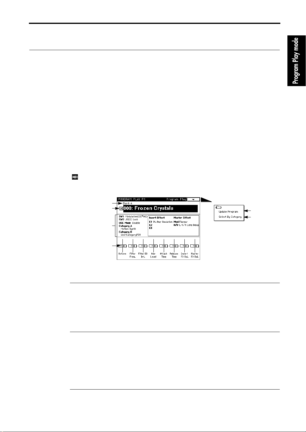
1–1: Program Play
Here you can select programs and make simple edits.
The center of the LCD shows the functions of the front panel SW1/SW2 switches, the program category, and information about the selected program (oscillator mode, etc.).
When you select a Performance Editor function (1–1c), Performance Editor information will
appear in the center right of the LCD.
In Program Play mode, all MIDI data is transmitted on the
Global mode “1–1c: MIDI Channel/Local Control On/Note Receive” (
1–1a
1–1b
Information on
the selected
program
1–1c
Global MIDI Channel
☞
page 130 in this manual).
Page Menu
specified in
1–1A
1–1B
(0–127 in
1–1a: Bank [Bank A…M]
Use the front panel [BANK] key to select the bank.
Banks A, B, C, and D are the
generator programs
On the
TRINITY series
option is installed. Bank M can be selected only if the MOSS-TRI option is installed.
ACCESS tone generator programs
.
, banks C and D can be selected only if Playback Sampler/Flash ROM
, and bank M is for the
MOSS tone
1–1b: Program Number/Program Name [0…127]
Use the VALUE controller or a foot pedal to select programs.
For details on using a foot pedal to select programs, or using Program Change messages from an
external MIDI device to select programs, refer to Basic Guide page 13 “2. Select and play a program.”
If the MOSS-TRI option is installed, you can select programs 0–63 from bank M. If the Playback
Sampler/Flash ROM option is installed as well, you can select programs 0–127 from bank M.
1–1c: Performance Editor
The Performance Editor allows you to edit major parameters without having to move to Program
Edit mode. This is a “macro” editing function which simultaneously modifies multiple parameters
1
Page 10

1–1: Program Play
within a program, and provides an easy way to shape the overall character of the sound. This can
be used when you wish to adjust the sound as you play, or to make rough settings when creating
an original sound.
Edits you perform here will affect the values of the program parameters in the edit buffer. When
you select a Performance Editor function (1–1c), the Performance Editor data will be displayed in
the center right of the LCD, and you can see the value changes that result from your editing. If you
want to keep your edits, use the Program Write operation. (
☞
Basic Guide, page 23)
The Performance Editor adjusts the values that are set for the program parameters. The Performance Editor cannot modify a value beyond the range of the program parameters. Since these
are rough edits, the balance between parameters may sometimes be affected.
If you check the Global mode “2–1a: Filter” (
☞
page 136 in this manual) parameter Enable Exclusive, parameter changes will be transmitted as MIDI Exclusive messages each time you operate
the Performance Editor.
If these messages are received by another
TRINITY series
instrument (on which the Enable Exclusive parameter is checked), that instrument will execute the corresponding Performance Editor
operations.
Octave [–3…0…+3]
A setting of +1 will raise the pitch 1 octave. It is not possible to raise the pitch above 4', or to lower
the pitch below 32'.
Filter Freq. (Filter Cutoff Frequency) [–10…0…+10]
A setting of +1 will raise the cutoff frequency value by 5.
Filter EG Int. (Filter EG Intensity) [–10…0…+10]
With a setting of +1, the value of the parameters that adjust the depth of modulation applied by
the Filter EG to the cutoff frequency will each be increased by 5, causing the Filter EG to have a
greater influence on the cutoff frequency.
This parameter will not change the polarity (sign) of the parameter values. For example, if the Performance Editor value is set to –2, the parameter values will be decreased by 10, but if the original
parameter value is 8, the resulting parameter value will be 0 and not –2.
Amp Level [–10…0…+10]
A setting of +1 will increase the output level value by 5, producing a louder volume.
Attack Time [–10…0…+10]
A setting of +1 will increase the Amp EG attack time values by 5. For your refer ence, the LCD will
also display the attack time of the filter EG.
Release Time [–10…0…+10]
A setting of +1 will increase the Filter EG and Amp EG release time values by 5.
Insert FX Bal. (Insert Effect Dry/FX Balance) [–10…0…+10]
A setting of +1 will increase the value of the FX side by 5, so that the insert effect will be applied
more deeply.
Master FX Bal. (Master Effect Dry/FX Balance) [–10…0…+10]
A setting of
more deeply.
Octave Octave of Oscillator 1, 2
Filter Freq. Cutoff Freq of Filter 1A, 1B, 2A, 2B
Filter EG Int.
Amp Level Output Level of Amp 1, 2
Attack Time Attack Time of Amp 1, 2
Release Time
Insert FX Bal. Dry/FX Balance of Insert Effect
Master FX Bal. Dry/FX Balance of Master Effect
+1
will increase the value of the FX side by 5, so that the master effect will be applied
Filter EG Intensity of Filter 1A, 1B, 2A, 2B
Filter EG Int Mod By Velocity of Filter 1A, 1B, 2A, 2B
Alternate Modulation Intensity of Filter 1, 2
EG Release Time of Filter 1, 2
EG Release Time of Amp 1, 2
2
Page 11

1–1: Program Play
▼
Page Menu Command
1–1A: Update Program
This writes the edited program into the currently selected program number.
Be sure to write important programs. If you turn the power off or select another program before
writing the data, it cannot be recovered.
Refer to Basic Guide page 23, “9. Writing a Program or Combination”.
1–1B: Select By Category
This allows you to select programs using the categories that were specified in Program Edit mode.
For details refer to Basic Guide page 26, “11. Selecting by category.”
3
Page 12

1–1: Program Play
4
Page 13
1–1: Prog Basic (Program Basic)
2. Program Edit mode
Program Edit P1
Here you can make basic settings for a program, and make basic settings for the oscillator(s) that
will be used.
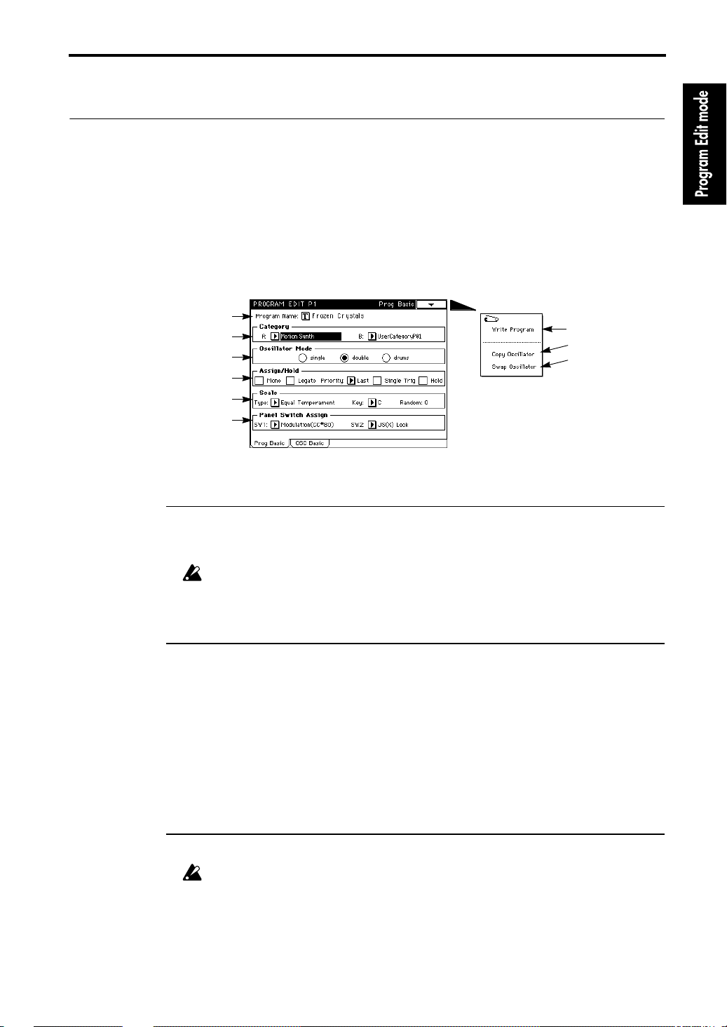
1–1: Prog Basic (Program Basic)
1–1a
1–1b
1–1c
1–1d
1–1e
1–1f
Page Menu
1–1A
1–1B
1–1C
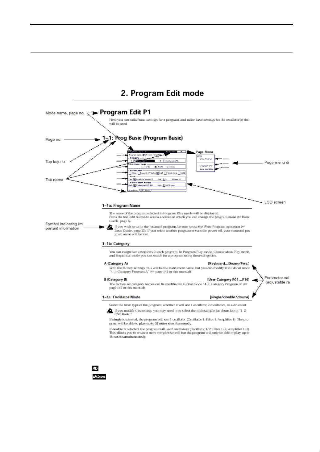
1–1a: Program Name
The name of the program selected in Program Play mode will be displayed.
Press the text edit button to access a screen in which you can change the program name (☞ Basic
Guide, page 6).
If you wish to write the renamed program, be sure to use the Write Program operation (
Basic Guide, page 23). If you select another program or turn the power off, your renamed program name will be lost.
☞
1–1b: Category
You can assign two categories to each program. In Program Play mode, Combination Play mode,
and Sequencer mode you can search for a program using these categories.
A (Category A) [Keyboard…Drums/Perc.]
With the factory settings, this will be the instrument name, but you can modify it in Global mode
“4–1: Category Program A” (
☞
page 141 in this manual).
B (Category B) [User Category P01…P16]
The factory set category names can be modified in Global mode “4–2: Category Program B” (
page 141 in this manual).
☞
1–1c: Oscillator Mode [single/double/drums]
Select the basic type of the program; whether it will use 1 oscillator, 2 oscillators, or a drum kit.
If you modify this setting, you may need to re-select the multisample (or drum kit) in “1–2:
OSC Basic.”
If
single
is selected, the program will use 1 oscillator (Oscillator 1, Filter 1, Amplifier 1). The pro-
gram will be able to
double
If
This allows you to create a more complex sound, but the program will only be able to
16 notes simultaneously
is selected, the program will use 2 oscillators (Oscillator 1/2, Filter 1/2, Amplifier 1/2).
play up to 32 notes simultaneously
.
.
play up to
5
Page 14

1–1: Prog Basic (Program Basic)
If
drums
used instead of a multisample for Oscillator 1.
1–1d: Assign/Hold
Assign
Mono
If Mono is
If Mono is
Monophonic means that the program will produce only 1 note at a time. Polyphonic means that
chords can be played.
Legato
This setting will be available only if Mono is checked.
If Legato is
If Legato is
If single triggering is used, there may be cases in which the correct pitch is not produced,
depending on the multisample and the keyboard position.
Priority
This setting will be available only if Mono is checked.
It determines which note will sound when two or more keys are pressed simultaneously.
Priority will be given to the lowest note for a setting of
High
, and to the last-pressed note with a setting of
Single Trig (Single Trigger)
This setting will be available only if Mono is not checked (i.e., for a
If this is
turned off, meaning that notes will not overlap.
is selected, the program uses 1 oscillator as when single is selected, but a drum kit will be
checked
, the program will be monophonic.
not checked
checked
not checked
checked
, the program will be polyphonic.
, the program will be single-triggered.
, the program will be multi-triggered.
Low
, to the highest note with a setting of
Last
.
, repeated strikes of the same note will be sounded only after the previous note is
polyphonic
program).
Hold [On/Off]
If Hold is
If Hold is
When
is released. Unless the “5–2 (5–4): Amp 1(2) EG” setting for Amp EG Sustain Level is set to 0, the
sound will continue sounding.
This setting is appropriate for drums, so if you have selected “drums” for “1–1c: Oscillator Mode”
you should set
checked
not checked
Hold is On
Hold On
, Hold will be On.
, Hold will be Off.
, the sound will continue as though the key remained pressed even after the key
. For normal programs, set
Hold Off
.
1–1e: Scale
Type (Scale Type) [Equal Temperament…All Range User Scale]
This selects the basic scale of the internal tone generator. Settings for the User Scales can be made
in Global mode 3–1: User Scale” (
Equal Temperament
interval.
Pure Major
tune.
Pure Minor
tune.
Arabic
Pythagoras
melodic playing.
Werkmeister
Kirnberger
Slendro
When the Scale Key is set to C, use the notes C, D, F, G, and A. (The other keys are tuned to equal
temperament.)
Pelog
When the Scale Key is set to C, use the white keys. (The black keys are tuned to equal temperament.)
Octave User Scale
manual) the tuning of each note in an octave. The default setting is the scale used for combination
A054: Real Harp Gliss.
is a scale in which the principal major chords of the selected key will be perfectly in
is a scale in which the principal minor chords of the selected key will be perfectly in
is a scale that includes 1/4 tones and is used in Arabian music.
is a scale derived from musical theories of ancient Greece, and is especially suitable for
is a scale that was developed in the 18th century, and used mainly by harpsichords.
is a scale which divides the octave into 5 notes, and is used in Indonesian Gamelan music.
is a scale which divides the octave into 7 notes, and is used in Indonesian Gamelan music.
is the most commonly used scale. Each chromatic step is spaced at an equal
is an equal tempered scale that was used in the later Baroque period.
allows you to specify in Global mode “3–1b: Octave Notes” (☞ page 140 in this
6
☞
page 140).
Page 15

1–1: Prog Basic (Program Basic)
Stretch
is a tuning for acoustic piano.
All Range User Scale
manual) the tuning of each note in the entire range (C–1 to G9).
allows you to specify in Global mode “3–1a: All Notes” (☞ page 140 in this
Key (Scale Key) [C…B]
Specify the tonic note of the selected scale.
Random [0…7]
As this value is increased, the pitch at which a note is sounded will become increasingly erratic.
Normally you will set this to
This setting is useful when you wish to simulate instruments which tend to have a naturally inaccurate pitch, such as analog synthesizers or acoustic instruments.
0
.
1–1f: Panel Switch Assign
These settings assign the functions of the front panel switches SW1 and SW2 (assignable panel
switches 1 and 2).
SW1 [JS(X)Lock…Modulation (CC #80)]
SW2 [JS(X)Lock…Modulation (CC #81)]
The same functions are available for assignment to SW1 and SW2 (except for Modulation), as follows.
If you use one of these switches to
touch, the selected controller will lock (LED lit) or unlock (LED unlit) each time you press SW1 (or
SW2).
If you press SW1 (or SW2) while operating a controller, the controller value will be fixed at the current value, and will not change further. For example if you select JS(+Y) Lock, and press SW1 (or
SW2) when the joystick has been moved away from you, the joystick (+Y) movement will be
locked (held) at that position, so that modulation will continue to apply even after the joystick is
returned to its normal position. By moving the joystick in the (–Y) direction you can then apply
two types of modulation at once.
When a controller is locked, that controller will not transmit MIDI messages, but the corresponding MIDI message will still be received.
With a setting of
and the normal pitch (LED unlit) each time you press SW1 (or SW2).
With a setting of
lit) and the normal pitch (LED unlit) each time you press SW1 (or SW2).
With a setting of
lit) each time you press SW1 (or SW2).
This is available only for the bank M programs.
CC#65 will be transmitted each time this is turned on/off (OFF value is 0, ON value is 127).
If
Modulation
Dynamic Modulation. This is the only function which differs between SW1 and SW2; SW1 is
CC#80, and SW2 is CC#81.
CC#80 (or CC#81) will be transmitted each time the switch is turned on/off (OFF value is 0, ON
value is 127).
Portamento Off
Program Play mode). On a
mento OFF is just to turn portamento on/off on an external device.
Octave Up
Octave Down
Portamento Off
is selected, the switch can be the source for Alternate Modulation or Effect
will have no effect unless you are using a program from bank M (selected in
Lock
a controller such as the joystick, ribbon controller, or after-
, the pitch will alternate between a pitch of one octave higher (LED lit)
, the pitch will alternate between a pitch of one octave lower (LED
, the portamento effect will alternate on (LED unlit) and off (LED
TRINITY
in which the MOSS-TRI option is not installed, the Porta-
7
Page 16

1–1: Prog Basic (Program Basic)
▼
Page Menu Command
1–1A: Write Program
This command writes an edited program into the specified program number of the specified bank.
Be sure to write important programs. If you turn the power off or select a differ ent program befor e
writing, the data cannot be recovered.
For details refer to Basic Guide page 23, “9. Writing a program or combination.”
1–1B: Copy Oscillator
This command copies the settings of oscillator 1 or 2 from the specified program to the oscillator of
the program being edited. You may also select a program from another bank as the copy source.
When copying Oscillator 2 to Oscillator 1, if Filter 1 EG, Amp 1 EG, Oscillator 1 LFO, or Filter 1
LFO is selected for Oscillator 2 AMS, the settings will be automatically converted from Filter 1
EG to Filter EG, from Amp 1 EG to Amp EG, from OSC 1 LFO to OSC LFO, and from Filter 1
LFO to Filter LFO.
1–1C: Swap Oscillator
This command exchanges the settings of oscillator 1 and 2 within the program being edited.
If Oscillator 2 with AMS settings of Filter 1 EG, Amp 1 EG, Oscillator 1 LFO, or Filter 1 LFO is
used for Oscillator 1 as a result of a Swap Oscillator command, the settings will be automatically converted from Filter 1 EG to Filter EG, from Amp 1 EG to Amp EG, from OSC 1 LFO to
OSC LFO, and from Filter 1 LFO to Filter LFO.
8
Page 17
1–2: OSC Basic (Oscillator Basic)
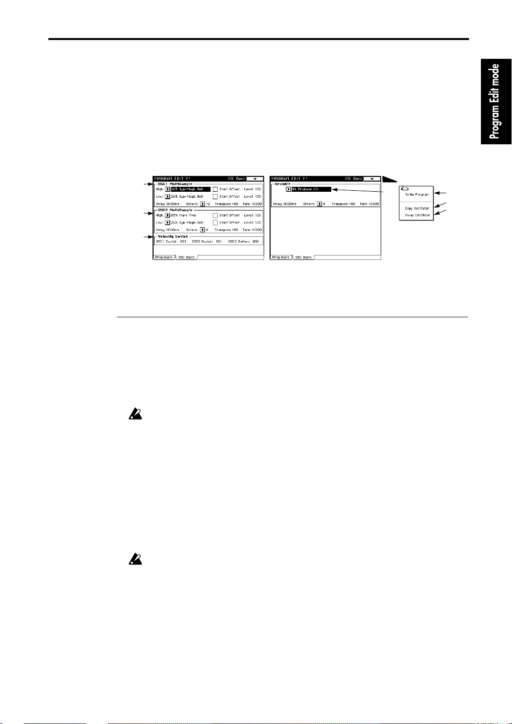
1–2: OSC Basic (Oscillator Basic)
Here you can select the multisample or drum kit (the basic waveform that is the core of the program) used by oscillators 1 and 2.
able for selection.
The screen on the left shows the LCD when “1–1c: Oscillator Mode” is set to “
is selected, “1–2b: OSC2 Multisample” will not be displayed.
The screen on the right shows the drum kit display that appears when “1–1c: Oscillator Mode” is
set to “
drums
.”
375 types
of multisamples and
12 types
of drum kits are avail-
double
.” If “
single
”
1–2a
1–2b
1–2c
Page Menu
1–2d
1–2a: OSC1 Multisample
This selects the multisample.
Y ou can select differ ent multisamples for High and Low, and use velocity to switch between them.
You can also adjust the sample’s start point and level for High and Low.
High [0…374]
The multisample selected here will be sounded by velocities greater than the OSC1 Switch setting
in “1–2c: Velocity Switch.” If you do not wish to use velocity to switch multisamples, set “OSC1
Switch” to
Low [0…374]
The multisample selected here will be sounded by velocities less than the OSC1 Switch setting in
“1–2c: Velocity Switch.”
1
, and select only the High multisample.
Since each multisample has an upper limit for the range that it can sound, playing very high
notes may sometimes produce no sound.
1–2A
1–2B
1–2C
Start Offset
This determines the point from which a multisample will be started when it is played.
If this is
checked
If this is
, the multisample will be started from the point fixed for each multisample.
unchecked
, the multisample will be started from the beginning of the waveform.
Level (Multisample Level) [0…127]
This sets the level of the multisample.
For some multisamples, high settings of this value may cause the sound to distort when
chords are played. In such cases, lower the level.
Delay (Delay Time) [0ms…5000ms, KeyOff]
This sets the delay from the Note-on until the sound begins.
With a setting of
KeyOff
, the sound will begin at Note-off. This is useful for recreating certain
nuances such as the sound of the keys being released on a harpsichord. In this case, set the Sustain
Level of the Amp EG to 0.
Octave [32'…4']
This sets the basic pitch in steps of one octave. The standard octave of each multisample is 8'.
9
Page 18

1–2: OSC Basic (Oscillator Basic)
Transpose [–12…+12]
Sets the pitch in chromatic steps over a range of ±1 octave.
Tune [–1200…+1200]
Adjusts the pitch in units of 1 cent (a chromatic step = 100 cents) over a range of ±1 octave.
To change the pitch more than a chromatic step, you will normally use the
However if you wish to produce an intentionally “stretched” sound (like the sound produced by
using pitch bend to raise the pitch), use the
1–2b: OSC2 Multisample
Tune
setting.
Transpose
setting.
These parameters will appear if “1–1c: Oscillator Mode” is set to
not sound for velocity values less than the value specified in “1–2c: Velocity Switch” for OSC2 Bottom.
For the function and settings of these parameters, refer to “1–2a: OSC1 Multisample”.
double
. This multisample will
1–2c: Velocity Switch
OSC1 Switch (OSC1 Velocity Switch) [1…127]
This velocity value will determine the point at which the High and Low multisamples specified
for oscillator 1 in “1–2a: OSC1 Multisample” will be switched.
Velocities above the value specified here will sound the High multisample.
OSC2 Switch (OSC2 Velocity Switch) [1…127]
This parameter will be displayed if “1–1c: Oscillator Mode” is set to
This velocity value will determine the point at which the High and Low multisamples specified
for oscillator 2 in “1–2b: OSC2 Multisample” will be switched.
Notes with velocity values higher than this setting will sound the multisample specified for High.
double
.
OSC2 Bottom (OSC2 Velocity Switch Bottom) [1…127]
This parameter will be displayed if “1–1c: Oscillator Mode” is set to
Velocities above the value specified here will sound the multisample of oscillator 2.
If this value is set higher than the OSC2 Switch setting, the Low multisample of oscillator 2
will never sound.
double
.
1–2d: OSC1 Drumkit
Drumkit [0…12]
Selects the drumkit.
10
Delay (Delay Time) [0ms…5000ms, KeyOff]
This sets the delay time from note-on until when the note sounds. With a setting of
sound will begin at note-off. In this case, set the Amp EG Sustain Level to 0.
KeyOff
, the
Octave [4'…32']
Specify the basic pitch of the oscillator in steps of one octave. When using a drumkit, be sure to set
this parameter to
When editing a drumkit program, be absolutely sure to set this parameter to
tings, the keyboard assignments of the drumkit will be thrown off.
8'
.
8'
. With other set-
Transpose [–12…+12]
This will adjust not the pitch but the location of the assigned drum kit.
If you do not need to change this, leave it set at
0
.
Tune [–1200…+1200]
This adjusts the pitch in units of 1 cent.
Pitch settings for each drum sound in a drum kit can be made in Global mode “5–1: Drumkit” (
page 143 in this manual).
☞
Page 19

1–2: OSC Basic (Oscillator Basic)
▼
Page Menu Command
1–2A: Write Program
This command writes an edited program into the specified program number of the specified bank.
Be sure to write important programs. If you turn the power off or select a differ ent program befor e
writing, the data cannot be recovered.
For details refer to Basic Guide page 23, “9. Writing a program or combination.”
1–2B: Copy Oscillator
This command copies the settings of oscillator 1 or 2 from the specified program to the oscillator of
the program being edited. You may also select a program from another bank as the copy source.
When copying Oscillator 2 to Oscillator 1, if Filter 1 EG, Amp 1 EG, Oscillator 1 LFO, or Filter 1
LFO is selected for Oscillator 2 AMS, the settings will be automatically converted from Filter 1
EG to Filter EG, from Amp 1 EG to Amp EG, from OSC 1 LFO to OSC LFO, and from Filter 1
LFO to Filter LFO.
1–2C: Swap Oscillator
This command exchanges the settings of oscillator 1 and 2 within the program being edited.
If an Oscillator 2 with AMS settings of Filter 1 EG, Amp 1 EG, Oscillator 1 LFO, or Filter 1 LFO
is used for Oscillator 1 as a result of a Swap Oscillator command, the settings will be automatically converted from Filter 1 EG to Filter EG, from Amp 1 EG to Amp EG, from OSC 1 LFO to
OSC LFO, and from Filter 1 LFO to Filter LFO.
11
Page 20

2–1: OSC1 Pitch Mod (Oscillator Pitch Modulation)
Program Edit P2
The
TRINITY series
oscillators 1 and 2.
2–1: OSC1 Pitch Mod (Oscillator Pitch Modulation)
These settings determine the relation between keyboard position and the pitch of oscillator 1 (“2–
1a”), and make settings for six controllers that can affect the pitch of oscillator 1 (“2–1b” through
”2–1g”).
“2–1b” through ”2–1e” adjust the depth of pitch control for each controller. “2–1f” adjusts the
amount of pitch change produced by the oscillator EG. “2–1g” controls the amount of pitch
change produced by the oscillator LFO.
contains two oscillators. Here you can make pitch modulation settings for
2–1a
2–1b
2–1c
2–1d
2–1e
2–1f
2–1g
Page Menu
2–1A
2–1B
2–1C
2–1a: Pitch Slope [–1.0…+2.0]
Normally this will be set at
With positive
(+)
settings, playing higher on the keyboard will produce increasingly higher
pitches. With negative
lower pitches.
With a setting of
0
, keyboard position will not affect the pitch, and all keys will play the C4 pitch.
+1.0
.
(–)
settings, playing higher on the keyboard will produce increasingly
Keyboard tracking settings and the resulting pitch
2oct
Pitch
1oct
1oct
+2
+1
0
12
–1
C4 C5
Key
2–1b: Ribbon (X) [–12…+12]
This determines how the ribbon controller will affect the pitch. One octave is 12 units.
Pressing on the right half of the ribbon controller will raise the pitch with positive
lower the pitch for negative
(–)
settings. For example, if this is set to +12 and you press the right
end of the ribbon controller, the pitch will rise one octave. If this is set to –12 and you press the
right end of the ribbon controller, the pitch will fall one octave.
Since the pitch will be normal at the center of the ribbon controller, you can press and release on
the right half of the ribbon controller to simulate the hammering-on techniques used by a guitarist.
(+)
settings, and
Page 21

2–1: OSC1 Pitch Mod (Oscillator Pitch Modulation)
2–1c: JS (+X)
These settings determine how the pitch will change when the joystick is moved toward the right.
Intensity [–60…+12]
12 units are equal to one octave.
For example if this is set to +12 and you move the joystick all the way to the right, the pitch will
rise one octave.
Step [Continuous, 1/8…12]
Each unit of 1 is a semitone. Normally this will be set to Continuous.
If Continuous is selected, the pitch will change smoothly when the joystick is moved toward the
right.
If a setting other than Continuous is selected, the pitch will change in increments of the specified
interval.
Since the Intensity parameter determines the range of pitch change, there will be no pitch
change if the Step setting is larger than the Intensity setting.
2–1d: JS (–X)
These settings determine how the pitch will change when the joystick is moved toward the left.
Intensity [–60…+12]
12 units are equal to one octave.
For example with a setting of –60, moving the joystick all the way to the left will lower the pitch
five octaves. This produces an effect similar to pressing the vibrato arm of a guitar (be sure to set
Step to Continuous).
Step [Continuous, 1/8…12]
Each unit of 1 is a semitone. Normally this will be set to Continuous.
For details refer to “2–1c: JS(+X).”
2–1e: Alternate Modulation
These settings determine how the Alternate Modulation Source will modulate the pitch.
AMS (Alternate Modulation Source) [OFF…Tempo]
Select the source which will modulate the pitch of oscillator 1.
With a setting of OFF, modulation will not be applied.
Intensity [–12.00…+12.00]
This determines the depth of the modulation applied to pitch.
With a setting of 0, no modulation will be applied.
If AMS is set to Tempo and this parameter is set to +12.00, the pitch will rise one octave when the
tempo which is input ( q =120 is standard) is increased to twice its speed.
If AMS is set to EG or LFO, the pitch can be modified to a maximum of ±1 octave. (The LFO can
add an additional ±1 octave of adjustment to the offset.) For example if AMS is set to Filter LFO,
you can apply vibrato that is synchronized to the filter wah effect, and this parameter will control
the depth of vibrato.
If AMS is set to a controller (Joy Stick (+Y), etc.), positive (+) settings of Intensity will raise the
pitch, and negative (–) settings will lower the pitch. The range of this pitch change is a maximum
of 1 octave.
In this way, AMS and Intensity work together to determine how the pitch is modulated.
For details on how Alternate Modulation and the other AMS functions operate, refer to page 157
“8. Appendix” in this manual and to page 33 “About alternate modulation” in the Basic Guide.
13
Page 22
2–1: OSC1 Pitch Mod (Oscillator Pitch Modulation)
2–1f: Oscillator EG
These settings (Intensity, Velocity, and Alternate Modulation) affect the depth of the pitch modulation produced by the oscillator EG settings of “2–5: OSC EG.”
Intensity [–12.00…+12.00]
With a setting of 12.00, the change will be a maximum of ± one octave.
Velocity [–99…+99]
With positive (+) settings, the pitch change will increase beyond the width specified by Intensity
as you play more strongly (maximum ±1 octave).
With negative (–) settings, the pitch change will decrease below the width specified by Intensity as
you play more strongly (maximum ±1 octave).
Regardless of whether this parameter is set to a positive (+) or a negative (–) value, the settings of
Intensity will be approached as you play more softly.
Pitch change (level)
Note-on
Note-off
Note-on
Note-off
Note-on
Note-off
Softly played notes
(Intensity settings)
Strongly played with
negative (–) settings
Strongly played with
positive (+) settings
Alternate Modulation
AMS (Alternate Modulation Source) [OFF…Tempo]
Select the source that will control the depth of the pitch modulation produced by the oscillator EG.
With a setting of OFF, there will be no modulation.
Intensity [–12.00…+12.00]
If AMS is set to Controller, setting this parameter to a positive (+) value will deepen the pitch
modulation produced by the oscillator EG. Negative (–) values will invert the effect.
If AMS is set to SW1 or SW2, you can turn the switch On to apply modulation only when desired.
If the value of this parameter plus the value of the above Oscillator EG Intensity totals 0, modulation will be turned off when you turn the switch On.
If AMS is set to Tempo, setting this parameter to a positive (+) value will cause modulation to
deepen as the tempo is increased. However if the tempo is decreased below 120 ( q =120), modula-
tion will be applied with inverted polarity. If you do not want to apply modulation with inverted
polarity, make adjustments to the above (Oscillator EG) Intensity as well. With negative (–) settings, the effect will be reversed.
If AMS is set to Note Number, setting this parameter to a positive (+) value will cause modulation
to deepen as the note number increases (as you play higher notes). However if the note number
decreases below C4 (lower notes), modulation will be applied with inverted polarity. If you do not
want to apply modulation with inverted polarity, make adjustments to the above (Oscillator EG)
Intensity as well. With negative (–) settings, the effect will be reversed.
If AMS is set to Controller and this parameter is set to +12.00, you can apply ±1 octave of pitch
modulation when the oscillator EG is not applying pitch modulation. If AMS is Note Number, ±1
octave of pitch modulation will be applied when you move two octaves (if AMS is Note Number)
or when the tempo doubles (if AMS is Tempo).
For details on how Alternate Modulation and the other AMS functions operate, refer to page 157
“8. Appendix” in this manual and to page 33 “About alternate modulation” in the Basic Guide.
14
2–1g: Oscillator 1 LFO
These settings (Intensity, JS(+Y), After Touch, and Alternate Modulation) affect the pitch modulation produced by the oscillator 1 LFO settings of “2–2: OSC1 LFO.”
Intensity [–12.00…+12.00]
With a setting of 12.00, a maximum of ±1 octave of pitch modulation will be applied.
Page 23

2–1: OSC1 Pitch Mod (Oscillator Pitch Modulation)
JS(+Y) (Joy Stick (+Y)) [0…99]
Higher settings of this value will cause more modulation to be applied by the oscillator 1 LFO
when the joystick is pushed away from you.
Aftertouch [0…99]
Higher settings of this value will cause more pitch modulation to be applied by the oscillator 1
LFO when pressure is applied to the keyboard.
Alternate Modulation
AMS (Alternate Modulation Source) [OFF…Filter1 LFO]
Select the source that will control the depth of the pitch modulation produced by oscillator 1 LFO.
With a setting of OFF, there will be no modulation.
Intensity [–12.00…+12.00]
If AMS is set to EG or LFO, the depth of modulation can be controlled over the full range. If the
EG or LFO level passes into the negative (–) range, the polarity of the modulation will be inverted.
If AMS is set to Controller, setting Intensity to a positive (+) value will make modulation deeper,
and to a negative (–) value will make it shallower.
If AMS is set to SW1 or SW2, setting this parameter to a positive (+) value and turning the switch
On will allow you to apply modulation only when desired. If the sum of this value and the Intensity value of the Oscillator 1 LFO Intensity of the previous page is 0, modulation will be turned off
when the switch is turned on.
If AMS is set to Tempo, setting this parameter to a positive (+) value will cause modulation to
deepen as the tempo is increased. However if the tempo is decreased below 120 ( q =120), modula-
tion will be applied with inverted polarity. If you do not want the polarity to be inverted, you
must also make adjustments to the Oscillator 1 LFO Intensity on the previous page. With negative
(–) settings, this will be reversed.
If AMS is set to Note Number and this parameter is set to a positive (+) value, modulation will
deepen as the note number increases (i.e., as you play higher notes). However if the note number
is below C4, modulation will be applied with inverted polarity. If you do not want the polarity to
be inverted, you must also make adjustments to the Oscillator LFO Intensity on the previous page.
With negative (–) settings, this will be reversed.
If AMS is set to Note Number, ±1 octave of pitch modulation will be applied when you move two
octaves. If AMS is set to Tempo, ±1 octave of pitch modulation will be applied when the tempo
doubles.
For details on how Alternate Modulation and the other AMS functions operate, refer to page 157
“8. Appendix” in this manual and to page 33 “About alternate modulation” in the Basic Guide.
▼ Page Menu Command
2–1A: Write Program
This command writes an edited program into the specified program number of the specified bank.
Be sure to write important programs. If you turn the power off or select a differ ent program befor e
writing, the data cannot be recovered.
For details refer to Basic Guide page 23, “9. Writing a program or combination.”
2–1B: Copy Oscillator
This command copies the settings of oscillator 1 or 2 from the specified program to the oscillator of
the program being edited. You may also select a program from another bank as the copy source.
When copying Oscillator 2 to Oscillator 1, if Filter 1 EG, Amp 1 EG, Oscillator 1 LFO, or Filter
1 LFO is selected for Oscillator 2 AMS, the settings will be automatically converted from Filter
1 EG to Filter EG, from Amp 1 EG to Amp EG, from OSC 1 LFO to OSC LFO, and from Filter 1
LFO to Filter LFO.
2–1C: Swap Oscillator
This command exchanges the settings of oscillator 1 and 2 within the program being edited.
If an Oscillator 2 with AMS settings of Filter 1 EG, Amp 1 EG, Oscillator 1 LFO, or Filter 1 LFO
is used for Oscillator 1 as a result of a Swap Oscillator command, the settings will be automatically converted from Filter 1 EG to Filter EG, from Amp 1 EG to Amp EG, from OSC 1 LFO to
OSC LFO, and from Filter 1 LFO to Filter LFO.
15
Page 24
2–2: OSC1 LFO (Oscillator 1 LFO)
2–2: OSC1 LFO (Oscillator 1 LFO)
Here you can make settings for the LFO that applies cyclic changes (vibrato) to the pitch of oscillator 1. The depth of the effect that these LFO settings will have on the pitch of oscillator 1 is
adjusted in “2–1g: Oscillator 1 LFO” (☞ page 14 in this manual).
2–2a
2–2b
2–2c
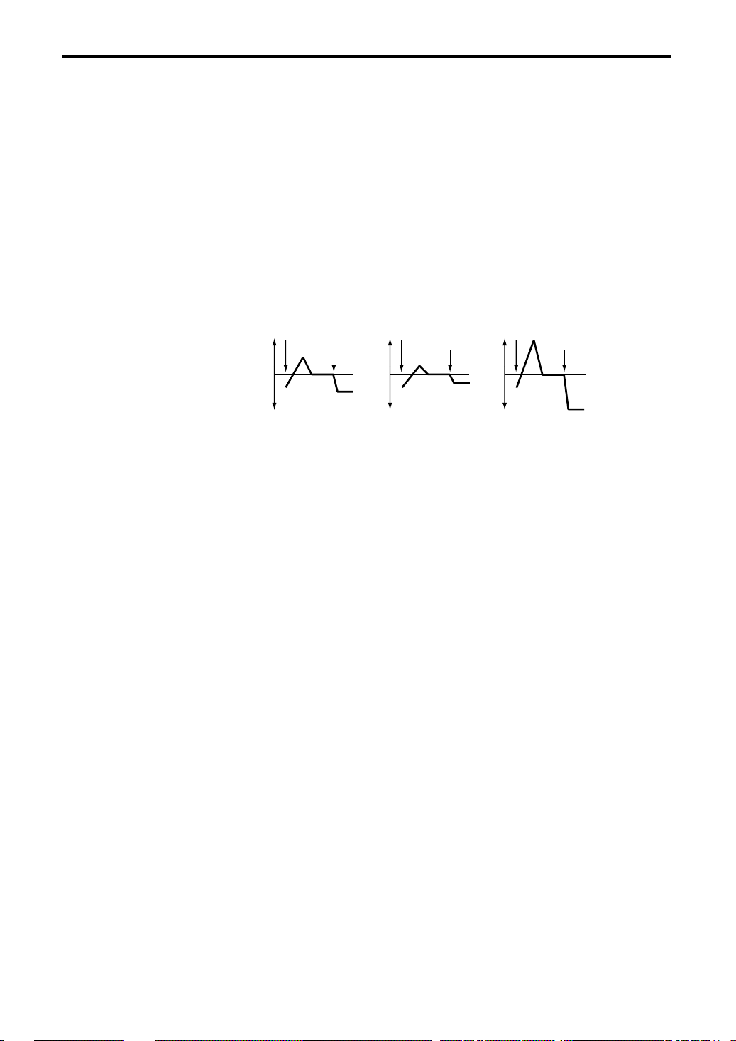
2–2a: Waveform/Freq (Frequency)/Offset
Waveform [Triangle 0…Random6]
Selects the LFO waveform.
The numbers at the right of each waveform name indicate the phase (height) at which the wave-
form starts (except for Random).
Random 1–3 are sample & hold waveforms.
Random 1 is a conventional sample & hold waveform that changes level randomly at fixed intervals.
Random 2 will change level randomly at random intervals.
Random 3 will change between the maximum level and the minimum level at random intervals
(i.e., a pulse wave with random width).
Random 4–6 are smoothed versions of Random 1–3. They can be used to simulate the natural
instability of acoustic instruments.
Page Menu
2–2A
2–2B
2–2C
16
LFO waveforms
180
270
180
180
0
90
Triangle wave
0
Sawtooth wave
0
Sawtooth wave
Rectangle
Rectangle
Sine
Sine
Guitar
Random
Random
Random
Random
Random
Random
180
180
0
Square wave
0
1
2
3
4
5
6
Sine wave
Guitar vibrato
Random
Triangle
Triangle
Triangle
Triangle
Up Saw
Up Saw
Down Saw
Down Saw
Freq (Frequency) [0…99]
Specify the LFO frequency.
A setting of 99 is the fastest.
Page 25
2–2: OSC1 LFO (Oscillator 1 LFO)
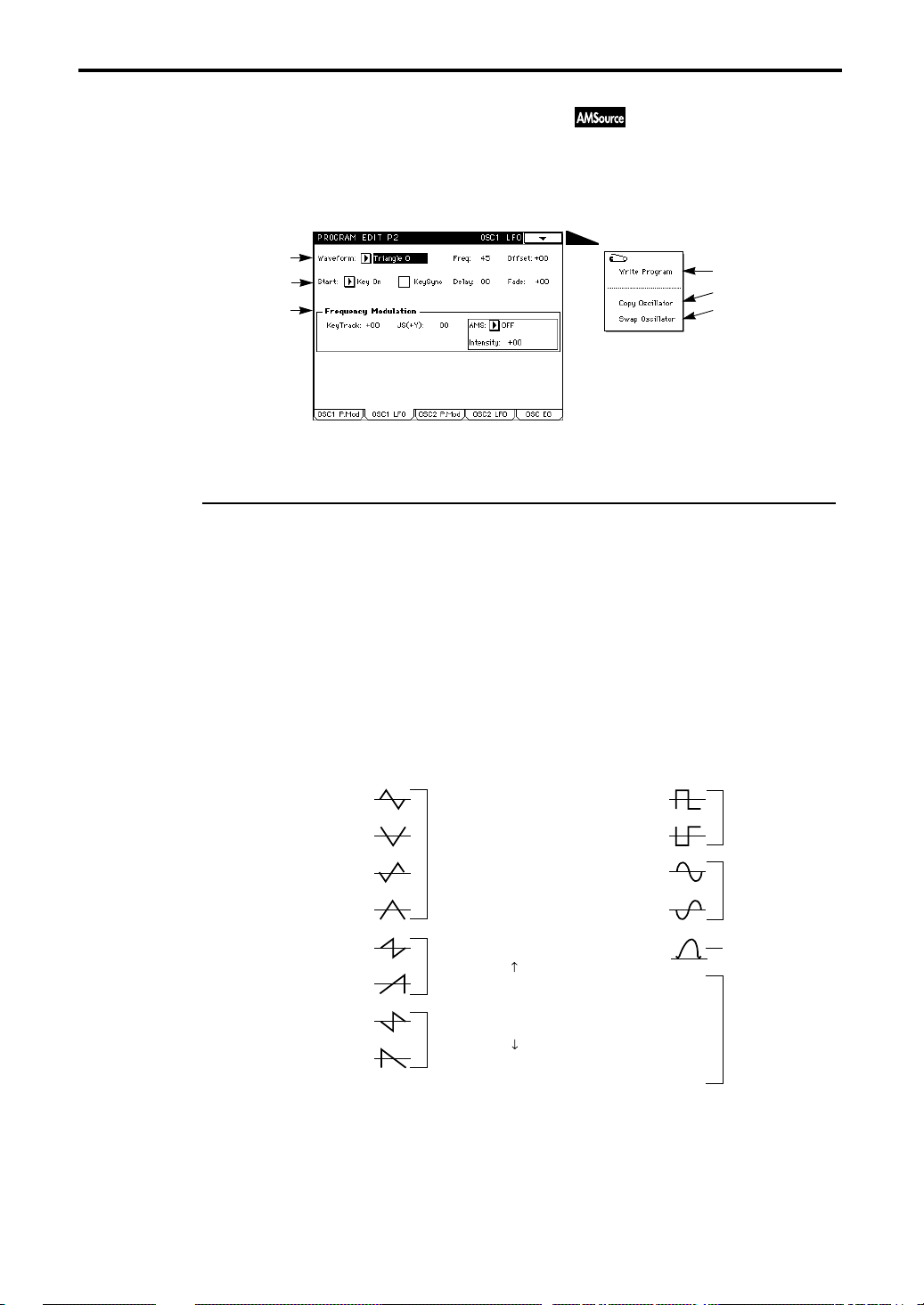
Offset [–99…+99]
With a setting of 0, vibrato will be applied while keeping the original frequency (at Note-on) at the
center of the vibrato. With a setting of +99, vibrato will be applied only in the upward direction,
similar to the way in which vibrato occurs on a guitar.
For the Guitar waveform, the modulation will be only in the positive direction even if the Offset is
set to 0.
Offset settings and vibrato pitch change
offset = –99 offset = 0 offset = +99Pitch
Original pitch at
Note-on
2–2b: Start/KeySync/Delay/Fade
Start [Key On, Key Off, Both]
This specifies the time at which the LFO will take effect. This setting is closely dependent on the
Fade setting, so refer to the explanation for Fade as well.
If Key On is selected, the LFO will begin taking effect at note-on. Normally you will set this to Key
On.
If Key Off is selected, the LFO will begin taking effect at note-off.
If Both is selected, the LFO will begin taking effect at note-on, and will stop taking effect at noteoff.
KeySync (Keyboard Sync) [On/Off]
If this is checked it will be On; the LFO will start each time you play a note, and an independent
LFO for each key will be used.
If this is un-checked it will be Off; the LFO effect begun by the first-played note will continue to
apply to subsequently played notes. (In this case, Delay and Fade will apply only to the firststarted LFO.)
Delay [0…99]
This determines the time from the Note-on (or Note-off) until the LFO begins to take effect. If KeySync is Off, the Delay setting will affect only the first-started LFO.
Fade [–99…+99]
With positive (+) settings, this will set the LFO Fade In Time; i.e., the time from when the LFO
begins to take effect until it reaches maximum amplitude.
With negative (–) settings, this will set the LFO Fade Out Time; i.e., the time over which the LFO
amplitude decreases from maximum down to 0.
If KeySync is Off, this will affect only the first-started LFO.
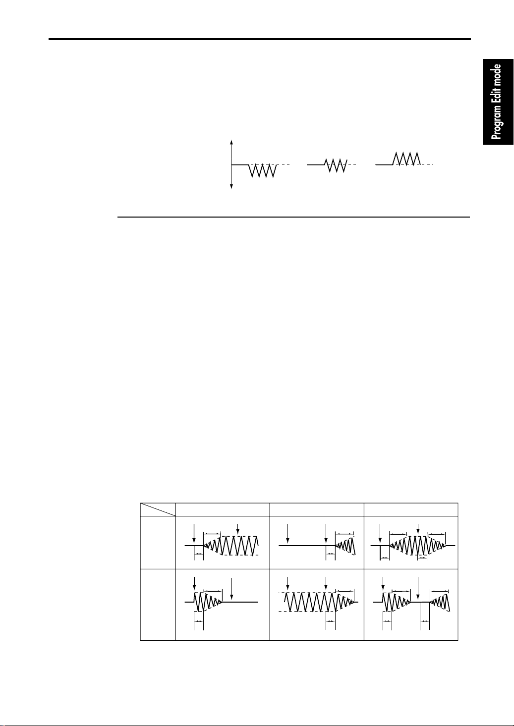
How the LFO is affected by Start and Fade settings (with KeySync On)
Fade
+ Values
– Values
Start
Key On
Note-on Note-off
Fade
Note-on Note-off Note-on Note-off Note-on Note-off
Fade
Key Off Both
Note-on Note-off Note-on Note-off
Fade
Fade
Fade Fade
DelayDelayDelay Delay
Fade
Fade
Delay
DelayDelayDelay
17
Page 26

2–2: OSC1 LFO (Oscillator 1 LFO)
2–2c: Frequency Modulation
These settings (KeyTrack, JS(+Y), Alternate Modulation) affect the speed of the oscillator 1 LFO.
KeyTrack (Keyboard Tracking) [–99…+99]
With positive (+) settings, the oscillator 1 LFO will become faster as you play higher on the keyboard.
With a setting of +33, the LFO speed will double as you play one octave higher on the keyboard,
and will be halved as you play one octave lower on the keyboard. Similarily, with a setting of +66,
the LFO speed will be increased to 4 times (decreased to 1/4th), and with a setting of +99 to 8
times (decreased to 1/8th).
With negative (–) settings, the oscillator 1 LFO will become slower as you play higher on the keyboard. The relation between the parameter value and the change in speed will be the opposite
from positive values.
With a “1–2: OSC” setting (☞ page 9 in this manual) of 8' the center key will be C4.
JS (+Y) (Joy Stick (+Y)) [0…99]
The higher this value is set, the faster the oscillator 1 LFO speed will become when you push the
joystick away from you.
With a setting of 99, the LFO speed will be increased by appr oximately 64 times when the joystick
is pushed all the way forward.
Alternate Modulation
AMS (Alternate Modulation Source) [OFF…Tempo]
Select the source that will control the frequency of the oscillator 1 LFO.
With a setting of OFF, there will be no modulation.
Intensity [–99…+99]
The time-related parameters of the LFO (“2–2a: Freq”, “2–2b: Delay, Fade”) can be temporarily
changed by the selected Alternate Modulation Source.
With settings of 16, 33, 49, 66, 82, and 99, the LFO time-related parameters will be multiplied
respectively by up to 2, 4, 8, 16, 32, and 64 times (or decreased by 1/2, 1/4, 1/8, 1/16, 1/32, or 1/
64).
If AMS is set to EG or LFO, the maximum available range of control allows the time-related
parameters to be modified over a range from 1/64th to 64 times their original values. (The LFO
allows an additional offset to be specified.)
If AMS is set to Controller, positive (+) values of this parameter will allow time-related parame-
ters to be shortened, to a maximum of 1/64th of their original time values. With negative (–) val-
ues, time-related parameters will be lengthened, to a maximum of 64 times the original values.
If AMS is set to SW1 or SW2, the time-related parameters can be shortened to as little as 1/64th or
lengthened to as great as 64 times their original value.
If AMS is set to Tempo, a setting of +16 for this parameter will cause the time-related parameters
to be shortened to half their original value when the tempo is doubled. This allows LFO speed to
track the tempo.
For details on how Alternate Modulation and the other AMS functions operate, refer to page 157
“8. Appendix” in this manual and to page 33 “About alternate modulation” in the Basic Guide.
18
Page 27

2–2: OSC1 LFO (Oscillator 1 LFO)
▼ Page Menu Command
2–2A: Write Program
This command writes an edited program into the specified program number of the specified bank.
Be sure to write important programs. If you turn the power off or select a differ ent program befor e
writing, the data cannot be recovered.
For details refer to Basic Guide page 23, “9. Writing a program or combination.”
2–2B: Copy Oscillator
This command copies the settings of oscillator 1 or 2 from the specified program to the oscillator of
the program being edited. You may also select a program from another bank as the copy source.
When copying Oscillator 2 to Oscillator 1, if Filter 1 EG, Amp 1 EG, Oscillator 1 LFO, or Filter 1
LFO is selected for Oscillator 2 AMS, the settings will be automatically converted from Filter 1
EG to Filter EG, from Amp 1 EG to Amp EG, from OSC 1 LFO to OSC LFO, and from Filter 1
LFO to Filter LFO.
2–2C: Swap Oscillator
This command exchanges the settings of oscillator 1 and 2 within the program being edited.
If an Oscillator 2 with AMS settings of Filter 1 EG, Amp 1 EG, Oscillator 1 LFO, or Filter 1 LFO
is used for Oscillator 1 as a result of a Swap Oscillator command, the settings will be automatically converted from Filter 1 EG to Filter EG, from Amp 1 EG to Amp EG, from OSC 1 LFO to
OSC LFO, and from Filter 1 LFO to Filter LFO.
19
Page 28

2–3: OSC2 Pitch Mod (Oscillator 2 Pitch Modulation)
2–3: OSC2 Pitch Mod (Oscillator 2 Pitch Modulation)
This page will be displayed if “1–1c: Oscillator Mode” is set to double.
Makes settings related to keyboard and pitch, and for the six controllers which can affect the pitch
of oscillator 2.
For details on the parameters, refer to “2–1: OSC1 Pitch Mod.”
2–4: OSC2 LFO (Oscillator 2 LFO)
This page will be displayed if “1–1c: Oscillator Mode” is set to double.
Makes settings for the LFO that will cyclically modulate the pitch of oscillator 2. Settings in “2–3g:
Oscillator LFO” will determine the depth of the effect that the LFO will have on the pitch of oscillator 2.
For details on the parameters, refer to “2–2: OSC1 LFO.”
20
Page 29
2–5: OSC EG (Oscillator Envelope Generator)
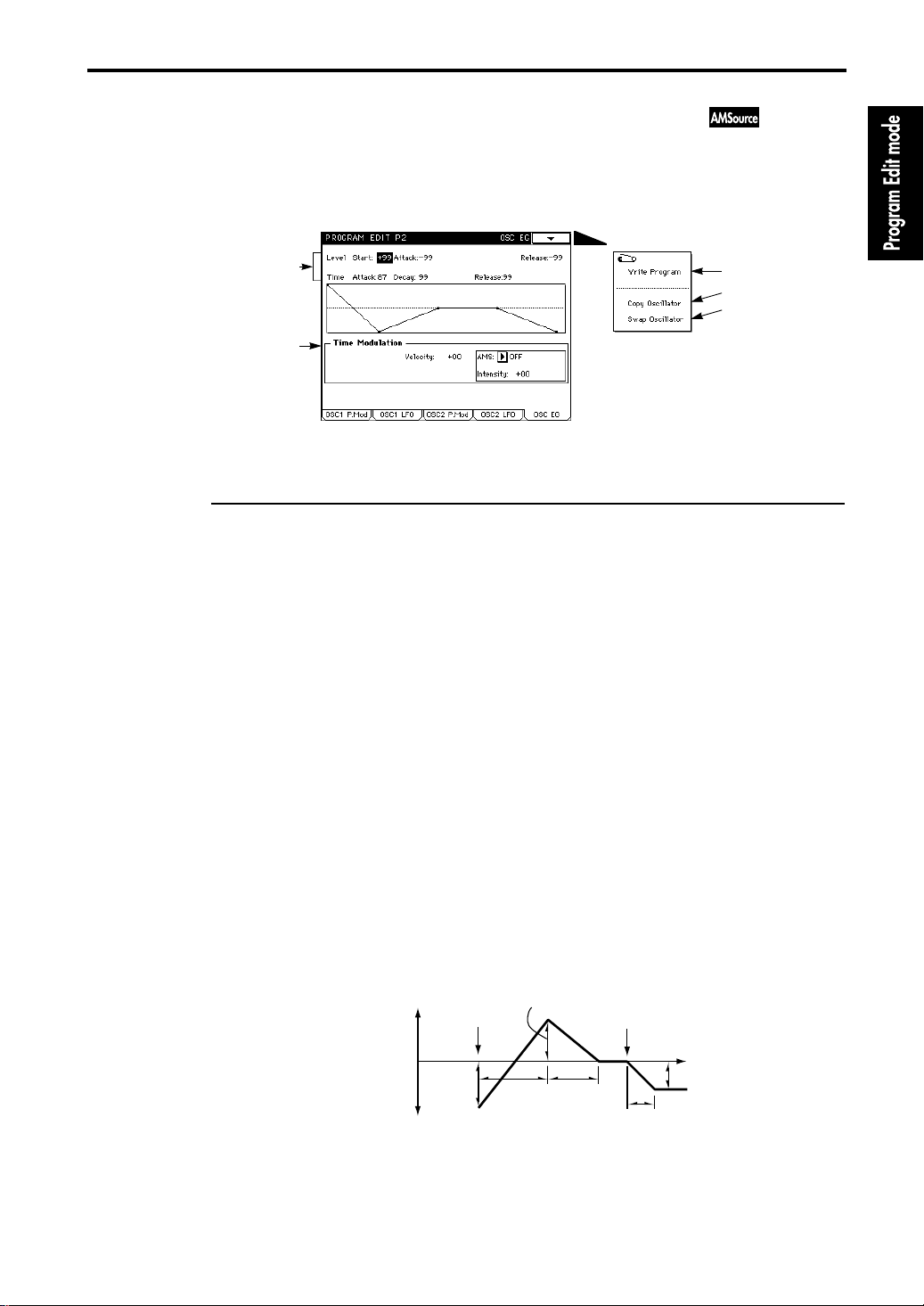
2–5: OSC EG (Oscillator Envelope Generator)
This page contains settings for the oscillator EG that creates time-variant changes in the pitch of
oscillators 1 and 2. The depth of the pitch change produced by this EG is adjusted in “2–1f(2–3f):
Oscillator EG.”
Page Menu
2–5a
2–5b
2–5a: OSC EG
Makes Level and Time settings to specify how the pitch will change over time.
Level
The operation of this parameter depends on the setting of “2–1f(2–3f): Oscillator EG” Intensity . For
example with a setting of +12.00, a setting of +99 will raise the pitch one octave, and –99 will lower
the pitch one octave.
Start (Start Level) [–99…+99]
Sets the pitch level at which the sound will begin at the time of Note-on.
Attack (Attack Level) [–99…+99]
Sets the pitch level that will be reached when the Attack Time has elapsed.
Release (Release Level) [–99…+99]
Sets the pitch level that will be reached when the Release Time has elapsed.
2–5A
2–5B
2–5C
Time
Specifies the times over which the pitch will change.
Attack (Attack Time) [0…99]
Sets the time from note-on until the pitch specified by the Attack Level is reached.
Decay (Decay Time) [0…99]
Sets the time from when the Attack Level is reached until the normal pitch is reached.
Release (Release Time) [0…99]
Sets the time from note-off until the pitch specified by the Release Level is reached.
Settings for time-variant pitch change (when EG Intensity = +12.00)
+99 = approximately one octave
0 = the pitch
reached when
the key remains
pressed
–99 = approximately one octave
Start Level
Note-on
Attack
Time
Attack Level
Note-off
Time
Release Level
Decay Time
Release Time
21
Page 30

2–5: OSC EG (Oscillator Envelope Generator)
2–5b: Time Modulation
Specifies how the OSC EG Times set in “2–5a: OSC EG” will be affected by Velocity and Alternate
Modulation.
Velocity [–99…+99]
With positive (+) settings, Oscillator EG times will become shorter as you play more strongly.
With negative (–) settings, Oscillator EG times will become longer as you play more strongly.
Regardless of whether the value is positive (+) or negative (–), the Oscillator EG Times set for OSC
EG will be approached as you play less strongly.
Pitch change (time)
Note-on
Note-off
Note-on
Note-off
Note-on
Note-off
Softly played
(OSC EG setting)
Strongly played with
(+) setting
Strongly played with
(–) setting
Alternate Modulation
AMS (Alternate Modulation Source) [OFF…Filter1 LFO]
Select the source that will affect Oscillator EG Times.
If OFF is selected, Oscillator EG Times will not be affected.
Intensity [–99…+99]
EG Times between each point will be determined by the Alternate Modulation value at the
moment that each point is reached. For example, the Alternate Modulation value at the moment
that the Attack Level is reached will determine the Decay Time.
If this parameter is set to values of 16, 33, 49, 66, 82, and 99, the EG times will be multiplied r espectively by 2, 4, 8, 16, 32, and 64 (or 1/2, 1/4, 1/8, 1/16, 1/32, and 1/64).
If AMS is set to EG or LFO, the maximum available range of control allows the EG times to be
modified over a range from 1/64th to 64 times their original values. (The LFO allows an additional offset to be specified.)
If AMS is set to Controller, positive (+) settings of this parameter will allow EG times to be short-
ened, to a maximum of 1/64th of their original time values. With negative (–) settings, EG times
will be lengthened, to a maximum of 64 times the original values.
If AMS is set to SW1 or SW2, the EG times can be shortened to as little as 1/64th or lengthened to
as great as 64 times their original value.
If AMS is set to Tempo, setting this parameter to +16 will cause the EG times to be shortened to
half their original value when the tempo is doubled. This allows EG speed to track the tempo.
For details on how Alternate Modulation and the other AMS functions operate, refer to page 157
“8. Appendix” in this manual and to page 33 “About alternate modulation” in the Basic Guide.
22
Page 31

2–5: OSC EG (Oscillator Envelope Generator)
▼ Page Menu Command
2–5A: Write Program
This command writes an edited program into the specified program number of the specified bank.
Be sure to write important programs. If you turn the power off or select a differ ent program befor e
writing, the data cannot be recovered.
For details refer to Basic Guide page 23, “9. Writing a program or combination.”
2–5B: Copy Oscillator
This command copies the settings of oscillator 1 or 2 from the specified program to the oscillator of
the program being edited. You may also select a program from another bank as the copy source.
When copying Oscillator 2 to Oscillator 1, if Filter 1 EG, Amp 1 EG, Oscillator 1 LFO, or Filter 1
LFO is selected for Oscillator 2 AMS, the settings will be automatically converted from Filter 1
EG to Filter EG, from Amp 1 EG to Amp EG, from OSC 1 LFO to OSC LFO, and from Filter 1
LFO to Filter LFO.
2–5C: Swap Oscillator
This command exchanges the settings of oscillator 1 and 2 within the program being edited.
If an Oscillator 2 with AMS settings of Filter 1 EG, Amp 1 EG, Oscillator 1 LFO, or Filter 1 LFO
is used for Oscillator 1 as a result of a Swap Oscillator command, the settings will be automatically converted from Filter 1 EG to Filter EG, from Amp 1 EG to Amp EG, from OSC 1 LFO to
OSC LFO, and from Filter 1 LFO to Filter LFO.
23
Page 32

3–1: Filter 1 A/B (Filter 1A/Filter 1B)
Program Edit P3
The TRINITY series provides two filters; filter 1 for oscillator 1, and filter 2 for oscillator 2. Each of
these filters actually consists of two filters; i.e., filter 1A and 1B, and filter 2A and 2B.
If “1–1c: Oscillator Mode” is set to single, filter 1 will be used. If it is set to double, filters 1 and 2
will be used.
Filter settings are made in Program Edit P3 and P4.
3–1: Filter 1 A/B (Filter 1A/Filter 1B)
Here you can specify the connections for filters 1A and 1B, and make basic settings.
3–1a
3–1b
3–1c
3–1A
3–1B
3–1C
3–1D
3–1E
3–1a: Routing (Filter Routing) [parallel/serial/single/thru]
Specifies how filters 1A and 1B will be connected (refer to the diagram below).
If you wish to use Band Pass filters to create two peaks, select parallel.
If you wish to use Band Reject filters to create two valleys, select serial. In this case, setting filters
1A and 1B to the same settings will cause the cutoff slope to be more narrow.
If you wish to use only filter 1A, select single.
Page Menu
parallel
Filter 1A
Filter 1B
serial
single
thru
Filter 1A
Filter 1B
24
Filter 1A Filter 1B
Filter 1A Filter 1B
3–1b: Filter 1A
Makes basic settings for filter 1A.
Type (Filter Type) [Low Pass, High Pass, Band Pass, Band Reject]
Selects the filter type.
Frequency (Cutoff Frequency) [0…99]
Sets the cutoff frequency.
Page 33

Filter Type and Cutoff Frequency
3–1: Filter 1 A/B (Filter 1A/Filter 1B)
Level
Level
Level
Level
Low Pass
High Pass
Band Pass
Band Reject
Cutoff Frequency
This filter cuts the frequencies higher
than the cutoff frequency.
This is the most commonly used type of
filter, and can brighten or darken the
sound by cutting the overtones.
Frequency
This filter cuts the frequencies lower
than the cutoff frequency.
By cutting the lower frequencies, this
filter can make the sound thinner.
Frequency
This filter cuts all frequencies other than
in the region of the cutoff frequency.
Frequency
This filter cuts only the frequencies in the
region of the cutoff frequency.
Frequency
Trim [0…99]
Sets the level at which the audio signal output from oscillator 1 is input to filter 1A.
With high settings of this value, or if the Resonance value is high, or when chords are played,
the sound may be distorted. Adjust the volume in “5–1a: Amplifier Level.”
Resonance [00…31]
This setting emphasizes the overtones in the region specified by Frequency, adding tonal character
to the sound. Higher settings will produce a stronger effect.
Resonance Mod By Vel (Resonance Modulation By Velocity) [–99…+99]
This determines how velocity will control the amount of Resonance.
With positive (+) settings, playing more strongly will cause the resonance effect to become closer
to the effect specified by the Resonance setting, and playing more softly will decrease the resonance effect.
With negative (–) settings, playing more strongly will decrease the resonance effect, and playing
more softly will cause the resonance effect to become closer to the amount specified by the Resonance setting.
25
Page 34

3–1: Filter 1 A/B (Filter 1A/Filter 1B)
Low Pass
The result of applying Resonance
Level
High Pass
Band Pass
Band Reject
Level
Level
Level
Low Resonance setting
High Resonance setting
3–1c: Filter 1B
These parameters will be displayed if “1–1c: Oscillator mode” is set to double, and “3–1a: Routing” is set to parallel or serial.
For details refer to “3–1b: Filter 1A.”
26
▼ Page Menu Command
3–1A: Write Program
This command writes an edited program into the specified program number of the specified bank.
Be sure to write important programs. If you turn the power off or select a differ ent program befor e
writing, the data cannot be recovered.
For details refer to Basic Guide page 23, “9. Writing a program or combination.”
3–1B: Copy Oscillator
This command copies the settings of oscillator 1 or 2 from the specified program to the oscillator of
the program being edited. You may also select a program from another bank as the copy source.
When copying Oscillator 2 to Oscillator 1, if Filter 1 EG, Amp 1 EG, Oscillator 1 LFO, or Filter 1
LFO is selected for Oscillator 2 AMS, the settings will be automatically converted from Filter 1
EG to Filter EG, from Amp 1 EG to Amp EG, from OSC 1 LFO to OSC LFO, and from Filter 1
LFO to Filter LFO.
3–1C: Swap Oscillator
This command exchanges the settings of oscillator 1 and 2 within the program being edited.
If an Oscillator 2 with AMS settings of Filter 1 EG, Amp 1 EG, Oscillator 1 LFO, or Filter 1 LFO
is used for Oscillator 1 as a result of a Swap Oscillator command, the settings will be automatically converted from Filter 1 EG to Filter EG, from Amp 1 EG to Amp EG, from OSC 1 LFO to
OSC LFO, and from Filter 1 LFO to Filter LFO.
Page 35

3–1: Filter 1 A/B (Filter 1A/Filter 1B)
3–1D: Copy Filter
This command copies the settings of filter 1A to filter 1B, or the settings of filter 1B to filter 1A.
3–1E: Sync Filter AB (check command)
If this is checked, filters 1A and 1B will be edited simultaneously. (When you edit one filter, the
settings of the other filter will also change.)
By setting “3–1a: Routing” to serial and making the same settings for filters 1A and 1B, you can
create a sharper filter cut.
27
Page 36

3–2: Filter 1 Mod (Filter 1 Modulation)
3–2: Filter 1 Mod (Filter 1 Modulation)
Here you can modify the sound by applying modulation to the cutoff frequency of filter 1 (oscillator 1).
This tab page will be displayed if “3–1a: Routing” has a setting other than thru. If this setting is
single, the parameters for filter 1B will not be displayed.
3–2a
3–2b
3–2c
3–2d
Page Menu
3–2A
3–2B
3–2C
3–2D
3–2E
3–2a: Filter 1A Modulation
These settings specify how Keyboard Tracking, Joy Stick (X), Aftertouch, and Alternate Modulation will affect the cutoff frequency of filter 1. (This will produce a “wah” effect.)
Cutoff Freq Key Track (Cutoff Frequency Keyboard Track)
The following Key and Ramp parameters will specify how keyboard position affects the cutoff frequency (refer to the diagram on the next page).
Key (Keyboard Track Keys)
Specify the note numbers at which keyboard tracking will begin to apply. Between the Low and
High settings, the cutoff frequency will change in correspondence to the keyboard location (pitch).
• Low (Low Key) [C–1…G9]
Keyboard tracking will apply to the range below the specified note number.
The note number can also be specified from the keyboard.
• High (High Key) [C–1…G9]
Keyboard tracking will apply to the range above the specified note number.
The note number can also be specified from the keyboard.
Ramp (Ramp settings)
Specify the angles of the keyboard tracking.
• Low (Lower Ramp) [–99…+99]
• High (Higher Ramp) [–99…+99]
With a setting of +62, the angle of change (i.e., slope or tilt) for the cutoff frequency will be the
same as the keyboard location (pitch). This means that the oscillation that occurs when the resonance (“3–1b: Filter 1A”) is raised will track the keyboard position.
With a setting of –43, the cutoff frequency will have no slope; i.e., the cutoff frequency will be the
same for all notes.
28
Page 37

3–2: Filter 1 Mod (Filter 1 Modulation)
How keyboard position and the Ramp settings affect the cutoff frequency
Cutoff Frequency
Low Ramp=–99
Low Ramp=–43
Low Ramp=0
Low Ramp=+62
Low Ramp=+99
Low Key
High Key
High Ramp=+99
High Ramp=+62
High Ramp=0
High Ramp=–43
High Ramp=–99
Key
JS (X) (Joy Stick (X)) [–99…+99]
With positive (+) settings, moving the joystick to the right will raise the cutoff frequency and
brighten the sound.
With negative (–) settings, moving the joystick to the right will lower the cutoff frequency and
darken the sound.
Aftertouch [0…99]
The operation of this parameter will depend on the filter selected by the T ype setting of “3–1: Filter
1 A/B.”
For example with a Low Pass filter, positive (+) settings of this parameter will cause the cutoff frequency to be raised when you press down on the keyboard, brightening the sound.
With a setting of Low Pass, negative (–) settings of this parameter will cause the cutoff frequency
to be lowered when you press down on the keyboard, darkening the sound.
Alternate Modulation
AMS (Alternate Modulation Source) [OFF…Tempo]
Select the source which will control cutoff frequency modulation for filter 1A.
With a setting of OFF, modulation will not be applied.
Intensity [–99…+99]
Alternate Modulation can modify the cutoff frequency over a range nearly equivalent to the range
of human hearing.
If AMS is set to EG or LFO, the pitch can be modified to a maximum of ±8 octaves. (The LFO can
add an additional ±8 octaves of adjustment to the offset.)
If AMS is set to a controller, positive (+) settings of this parameter will raise the cutoff frequency,
and negative (–) settings will lower the cutoff frequency. The range of this change is a maximum of
10 octaves.
If AMS is set to SW1 or SW2, the cutoff frequency can be modified up to 10 octaves.
If AMS is set to Tempo, an Intensity setting of +10 will raise the cutoff frequency 1 octave when
the tempo doubles in speed.
For details on how Alternate Modulation and the other AMS functions operate, refer to page 157
“8. Appendix” in this manual and to page 33 “About alternate modulation” in the Basic Guide.
3–2b: Filter 1B Modulation
These parameters will be displayed if “1–1c: Oscillator mode” is set to double, and “3–1a: Routing” is set to parallel or serial.
These settings specify how Keyboard Tracking, Joy Stick (X), Aftertouch, and Alternate Modulation will affect the cutoff frequency of filter 1B.
For details refer to “3–2a: Filter 1A Modulation.”
3–2c: Filter 1 EG
These settings specify the depth of the effect produced by the filter 1 EG (make settings in “4–1:
Filter 1 EG”) that creates time-variant changes in the cutoff frequency of filter 1A and 1B.
29
Page 38

3–2: Filter 1 Mod (Filter 1 Modulation)
Velocity To 1A [–99…+99]
With positive (+) settings, the Filter 1 EG will change the cutoff frequency more greatly as you
play more strongly.
With negative (–) settings, the Filter 1 EG will operate in inverted polarity to change the cutoff frequency more greatly as you play more strongly.
Velocity To 1B [–99…+99]
Refer to the above explanation for “Velocity To 1A.”
Change in cutoff frequency (for positive (+) settings)
Note-on
Note-off
Note-on
Note-off
Note-on
Note-off
Softly played note
Settings of EG Intensity to 1A
Strongly played note
Intensity To A [–99…+99]
Adjust the depth with which the Filter EG (set in “4–1: Filter 1 EG”) will affect the cutoff frequency
of filter 1A and 1B.
With positive (+) settings, positive (+) EG levels set in “4–1a: Filter 1 EG Level/Time” will
brighten the sound, and negative (–) levels will darken the sound.
With negative (–) settings, positive (+) EG levels set in “4–1a: Filter 1 EG Level/Time” will darken
the sound, and negative (–) levels will brighten the sound.
Intensity To B [–99…+99]
Refer to the above explanation for “Intensity To A.”
Alternate Modulation
AMS (Alternate Modulation Source) [OFF…Tempo]
Select the source which will control modulation depth of the cutoff frequency of filter 1A and 1B.
With a setting of OFF, modulation will not be applied.
Intensity [–99…+99]
Refer to “2–1f: Oscillator EG.” The operation is essentially the same.
For details on how Alternate Modulation and the other AMS functions operate, refer to page 157
“8. Appendix” in this manual and to page 33 “About alternate modulation” in the Basic Guide.
3–2d: Filter 1 LFO
These settings adjust the depth of the cyclic change applied by the LFO (set in 4–2: Filter 1 LFO) to
the cutoff frequency of filters 1A and 1B.
30
JS(–Y) (Joy Stick (–Y)) [0…99]
As this setting is increased, moving the joystick toward you will cause the filter 1 LFO to have an
increasingly greater effect.
Change in cutoff frequency
Lower values
Higher values
Aftertouch [0…99]
As this setting is increased, pressing down on the keyboard will cause the filter 1 LFO to have an
increasingly greater effect.
Page 39

3–2: Filter 1 Mod (Filter 1 Modulation)
Intensity To A [–99…+99]
Adjust the depth with which the Filter 1 LFO will affect the cutoff frequency of Filter 1A. With
negative (–) settings, the polarity will be inverted.
Intensity To B [–99…+99]
Refer to the above explanation for “Intensity To A.”
Alternate Modulation
AMS (Alternate Modulation Source) [OFF…Filter1 LFO]
Select the source which will adjust the depth of cutoff frequency modulation for both filters 1A
and 1B.
With a setting of OFF, modulation will not be applied.
Intensity [–99…+99]
Refer to “2–1g: Oscillator LFO.” The operation is essentially the same.
For details on how Alternate Modulation and the other AMS functions operate, refer to page 157
“8. Appendix” in this manual and to page 33 “About alternate modulation” in the Basic Guide.
▼ Page Menu Command
3–2A: Write Program
This command writes an edited program into the specified program number of the specified bank.
Be sure to write important programs. If you turn the power off or select a differ ent program befor e
writing, the data cannot be recovered.
For details refer to Basic Guide page 23, “9. Writing a program or combination.”
3–2B: Copy Oscillator
This command copies the settings of oscillator 1 or 2 from the specified program to the oscillator of
the program being edited. You may also select a program from another bank as the copy source.
When copying Oscillator 2 to Oscillator 1, if Filter 1 EG, Amp 1 EG, Oscillator 1 LFO, or Filter 1
LFO is selected for Oscillator 2 AMS, the settings will be automatically converted from Filter 1
EG to Filter EG, from Amp 1 EG to Amp EG, from OSC 1 LFO to OSC LFO, and from Filter 1
LFO to Filter LFO.
3–2C: Swap Oscillator
This command exchanges the settings of oscillator 1 and 2 within the program being edited.
If an Oscillator 2 with AMS settings of Filter 1 EG, Amp 1 EG, Oscillator 1 LFO, or Filter 1 LFO
is used for Oscillator 1 as a result of a Swap Oscillator command, the settings will be automatically converted from Filter 1 EG to Filter EG, from Amp 1 EG to Amp EG, from OSC 1 LFO to
OSC LFO, and from Filter 1 LFO to Filter LFO.
3–2D: Copy Filter
This command copies the settings of filter 1A to filter 1B, or the settings of filter 1B to filter 1A.
3–2E: Sync Filter AB (check command)
If this is checked, filters 1A and 1B will be edited simultaneously. (When you edit one filter, the
settings of the other filter will also change.)
By setting “3–1a: Routing” to serial and making identical settings for filters 1A and 1B, you can
create a sharper filter cut.
31
Page 40

3–3: Filter 2 A/B (Filter 2A/Filter 2B)
3–3: Filter 2 A/B (Filter 2A/Filter 2B)
This page will be displayed if “1–1c: Oscillator Mode” is set to double.
Here you can make settings to specify how filters 2A and 2B are connected, and their basic settings.
Refer to “3–1: Filter 1 A/B.”
3–4: Filter 2 Mod (Filter 2 Modulation)
This page will be displayed if “1–1c: Oscillator Mode” is set to double.
Here you can make settings to specify how modulation is applied to filter 2 (for oscillator 2) to
affect the sound.
Refer to “3–2: Filter 1 Mod.”
32
Page 41

4–1: Filter 1 EG
Program Edit P4
The TRINITY series provides a Filter EG and a Filter LFO that can modulate the cutoff frequency
of the filters in filter 1 and 2.
Filter settings are made in Program Edit P3 and P4.
4–1: Filter 1 EG
Makes settings for the EG that will modify the cutoff frequencies of filters 1A and 1B.
These settings are adjusted by the settings in “3–2c: Filter EG” to determine the depth of the effect
on filter 1 cutoff frequency.
Page Menu
4–1a
4–1b
4–1c
4–1A
4–1B
4–1C
4–1D
4–1a: Filter 1 EG
Makes settings for Level and Time to specify how the filter 1 EG will produce time-variant contr ol.
Level
The operation of this parameter will depend on the filter Type selected in “3–1: Filter 1 A/B.” For
example if a Low Pass filter is selected, positive values of EG Intensity will cause the sound to
brighten with positive (+) settings of this parameter, or darken with negative (–) settings of this
parameter.
Start (Start Level) [–99…+99]
Specifies the amount of change to the cutoff frequency that will be in effect at Note-on.
Attack (Attack Level) [–99…+99]
Specifies the amount of change to the cutoff frequency that will be in effect after the Attack Time
has elapsed.
Break (Break Point Level) [–99…+99]
Specifies the amount of change to the cutoff frequency that will be in effect after the Decay Time
has elapsed.
Sustain (Sustain Level) [–99…+99]
Specifies the amount of change to the cutoff frequency that will be in effect after the Slope Time
has elapsed until Note-off.
Release (Release Level) [–99…+99]
Specifies the amount of change to the cutoff frequency that will be in effect after the Release Time
has elapsed.
Time
Makes time-related settings.
Attack (Attack Time) [0…99]
Specifies the time from Note-on until the Attack Level is reached.
Decay (Decay Time) [0…99]
Specifies the time from when the Attack Level is reached until the Break Point Level is reached.
33
Page 42

4–1: Filter 1 EG
Slope (Slope Time) [0…99]
Specifies the time from when the Decay Time elapses until the Sustain Level is reached.
Release (Release Time) [0…99]
Specifies the time from Note-off until the Release Level is reached.
Slope
Time
Note-off
Release
Time
Release Level
Time
Specified cutoff
frequency
Start
Level
Note-on
Attack Level
Attack
Time
Sustain Level
Break
Point Level
Decay
Time
4–1b: Time Modulation
Specifies how the EG times of filter 1 specified in “4–1a: Filter 1 EG” will be modified by Keyboard
Tracking, Velocity, and Alternate Modulation.
Keyboard Track
With positive (+) settings, EG times will become shorter as you play notes increasingly above C4.
With negative (–) settings, EG times will become longer as you play notes increasingly above C4.
With a setting of 0, the EG times will be as specified in “4–1a: Filter 1 EG.”
At (Attack Time) [–99…+99]
Adjusts the Attack Time.
Dc (Decay Time) [–99…+99]
Adjusts the Decay Time.
Sl (Slope Time) [–99…+99]
Adjusts the Slope Time.
Rl (Release Time) [–99…+99]
Adjusts the Release Time.
Changes in Time (all four parameters with positive (+) settings)
Note-on
Note-off
Note-on Note-on
Note-off
Note-off
34
Filter EG settings
A low note
A high note
Velocity
With positive (+) settings, EG times will be shortened as you play more str ongly. With negative (–)
settings, EG times will be lengthened as you play more strongly.
With a setting of 0, the EG times will be as specified in “4–1a: Filter 1 EG.”
At (Attack Time) [–99…+99]
Adjusts the Attack Time.
Dc (Decay Time) [–99…+99]
Adjusts the Decay Time.
Sl (Slope Time) [–99…+99]
Adjusts the Slope Time.
Rl (Release Time) [–99…+99]
Adjusts the Release Time.
Page 43

Changes in Time (all four parameters with positive (+) settings)
Note-on
Note-off
Note-on Note-on
Note-off
4–1: Filter 1 EG
Note-off
Filter EG settings
Softly played note
Strongly played note
Alternate Modulation
Unlike the modulation settings that allow Keyboard Tracking and Velocity to affect EG times,
Alternate Modulation cannot be set independently for each EG Time (Attack/Decay/Slope/
Release Time).
AMS (Alternate Modulation Source) [OFF…Tempo]
Selects the source which will control filter 1 EG times.
With a setting of OFF, modulation will not be applied.
Intensity [–99…+99]
Refer to “2–5b: Time Modulation.”
For details on how Alternate Modulation and the other AMS functions operate, refer to page 157
“8. Appendix” in this manual and to page 33 “About alternate modulation” in the Basic Guide.
4–1c: Level Modulation
Specifies how the filter 1 EG levels set in “4–1a: Filter 1 EG” will be modified.
Velocity
With positive (+) settings, EG levels will be raised as you play more str ongly. With negative (–) settings, EG levels will be lowered as you play more strongly.
With a setting of 0, the EG levels specified in “4–1a: Filter 1 EG” will be used.
St (Start Level) [–99…+99]
Adjusts the Start Level.
At (Attack Level) [–99…+99]
Adjusts the Attack Level.
Br (Break Point Level) [–99…+99]
Adjusts the Break Point.
Changes in Filter 1 EG (with all four at positive (+) settings)
Note-on
Note-off
Note-on
Note-off
Note-on
Note-off
Settings of 4–1a: Filter 1 EG
Softly played note
Strongly played note
35
Page 44

4–1: Filter 1 EG
▼ Page Menu Command
4–1A: Write Program
This command writes an edited program into the specified program number of the specified bank.
Be sure to write important programs. If you turn the power off or select a differ ent program befor e
writing, the data cannot be recovered.
For details refer to Basic Guide page 23, “9. Writing a program or combination.”
4–1B: Copy Oscillator
This command copies the settings of oscillator 1 or 2 from the specified program to the oscillator of
the program being edited. You may also select a program from another bank as the copy source.
When copying Oscillator 2 to Oscillator 1, if Filter 1 EG, Amp 1 EG, Oscillator 1 LFO, or Filter 1
LFO is selected for Oscillator 2 AMS, the settings will be automatically converted from Filter 1
EG to Filter EG, from Amp 1 EG to Amp EG, from OSC 1 LFO to OSC LFO, and from Filter 1
LFO to Filter LFO.
4–1C: Swap Oscillator
This command exchanges the settings of oscillator 1 and 2 within the program being edited.
If an Oscillator 2 with AMS settings of Filter 1 EG, Amp 1 EG, Oscillator 1 LFO, or Filter 1 LFO
is used for Oscillator 1 as a result of a Swap Oscillator command, the settings will be automatically converted from Filter 1 EG to Filter EG, from Amp 1 EG to Amp EG, from OSC 1 LFO to
OSC LFO, and from Filter 1 LFO to Filter LFO.
4–1D: Sync Both EGs (check command)
If this is checked, the filter 1 EG and the filter 2 EG will be edited simultaneously. (When you edit
one EG, the settings of the other EG will also change.)
36
Page 45

4–2: Filter 1 LFO
4–2: Filter 1 LFO
Here you can make settings for the LFO that applies cyclic changes to the cutoff frequency of filter
1 (wah effect). The depth of the effect that these LFO settings will have on the cutoff frequency of
filter 1 is adjusted in “3–2d: Filter LFO”.
Page Menu
4–2a
4–2b
4–2c
4–2a: Waveform/Freq/Offset
Waveform [Triangle 0…Random6]
Selects the LFO waveform. For the LFO waveforms that are available, refer to the explanation in
“2–2a: OSC1 LFO”.
4–2A
4–2B
4–2C
Freq (Frequency) [0…99]
Specifies the LFO frequency. A setting of 99 is the fastest.
Offset [–99…+99]
For details refer to the explanation of Offset in “2–2a: OSC1 LFO”.
If the setting is +99 and the cutoff frequency is fully raised, there will be no wah effect.
4–2b: Start/KeySync/Delay/Fade
For details on these settings, refer to “2–2b: Start/KeySync/Delay/Fade”.
Start [Key On, Key Off, Both]
This specifies the time at which the LFO will take effect. This setting is closely dependent on the
Fade setting, so refer to the explanation for Fade as well.
If Key On is selected, the LFO will begin taking effect at note-on. Normally you will set this to Key
On.
If Key Off is selected, the LFO will begin taking effect at note-off.
If Both is selected, the LFO will begin taking effect at note-on, and will stop taking effect at noteoff.
KeySync [On/Off]
If this is checked it will be On; the LFO will start each time you play a note, and an independent
LFO for each key will be used.
If this is un-checked it will be Off; the LFO effect begun by the first-played note will continue to
apply to subsequently played notes. (In this case, Delay and Fade will apply only to the firststarted LFO.)
Delay [0…99]
This determines the time from Note-on (or Note-off) until when the LFO begins to take effect. If
KeySync is Off, the Delay setting will affect only the first-started LFO.
Fade [–99…+99]
With positive (+) settings, this will set the LFO Fade In Time; i.e., the time from when the LFO
begins to take effect until when it reaches maximum amplitude.
37
Page 46

4–2: Filter 1 LFO
With negative (–) settings, this will set the LFO Fade Out Time; i.e., the time over which the LFO
amplitude decreases from maximum down to 0.
If KeySync is Off, this will affect only the first-started LFO.
4–2c: Frequency Modulation
These settings allow Alternate Modulation to affect the speed of the filter 1 LFO.
Alternate Modulation
AMS (Alternate Modulation Source) [OFF…Filter1 LFO]
Selects the source that will control the frequency of the oscillator 1 LFO.
With a setting of OFF, there will be no modulation.
Intensity [–99…+99]
Refer to “2–2c: Frequency Modulation.”
For details on how Alternate Modulation and the other AMS functions operate, refer to page 157
“8. Appendix” in this manual and to page 33 “About alternate modulation” in the Basic Guide.
▼ Page Menu Command
4–2A: Write Program
This command writes an edited program into the specified program number of the specified bank.
Be sure to write important programs. If you turn the power off or select a differ ent program befor e
writing, the data cannot be recovered.
For details refer to Basic Guide page 23, “9. Writing a program or combination.”
4–2B: Copy Oscillator
This command copies the settings of oscillator 1 or 2 from the specified program to the oscillator of
the program being edited. You may also select a program from another bank as the copy source.
When copying Oscillator 2 to Oscillator 1, if Filter 1 EG, Amp 1 EG, Oscillator 1 LFO, or Filter 1
LFO is selected for Oscillator 2 AMS, the settings will be automatically converted from Filter 1
EG to Filter EG, from Amp 1 EG to Amp EG, from OSC 1 LFO to OSC LFO, and from Filter 1
LFO to Filter LFO.
4–2C: Swap Oscillator
This command exchanges the settings of oscillator 1 and 2 within the program being edited.
If an Oscillator 2 with AMS settings of Filter 1 EG, Amp 1 EG, Oscillator 1 LFO, or Filter 1 LFO
is used for Oscillator 1 as a result of a Swap Oscillator command, the settings will be automatically converted from Filter 1 EG to Filter EG, from Amp 1 EG to Amp EG, from OSC 1 LFO to
OSC LFO, and from Filter 1 LFO to Filter LFO.
38
Page 47

4–3: Filter 2 EG
4–3: Filter 2 EG
This page will be displayed if “1–1c: Oscillator Mode” is set to double.
Here you can make settings for the filter EG that will create time-variant changes in the cutoff frequency of filter 2.
Refer to “4–1: Filter 1 EG”.
4–4: Filter 2 LFO
This page will be displayed if “1–1c: Oscillator Mode” is set to double.
Here you can make settings for the LFO that will create cyclic changes in the cutoff frequency of
filter 2 (a wah effect).
Refer to “4–2: Filter 1 LFO”.
39
Page 48

5–1: Amp 1 Mod (Amplifier 1 Modulation)
Program Edit P5
The TRINITY series provides two amps; amp 1 for oscillator 1, and amp 2 for oscillator 2.
5–1: Amp 1 Mod (Amplifier 1 Modulation)
Here you can make settings for the volume of oscillator 1 and how it will change.
5–1a
5–1b
5–1c
5–1a: Amplifier Level [0…127]
Page Menu
5–1A
5–1B
5–1C
Sets the volume of oscillator 1.
5–1b: Amplifier Modulation
Specifies how the volume of oscillator 1 will be affected by Keyboard Tracking, Velocity, Aftertouch, and Alternate Modulation.
Amplifier Keyboard Tracking
The following Key and Ramp parameters specify how keyboard position will affect the volume
(refer to the diagram on the following page).
Key (Keyboard Tracking Keys)
Specify the note numbers at which keyboard tracking will begin to apply. Keyboard tracking will
not affect the volume of the notes between Low and High.
• Low (Low Key) [C–1…G9]
Keyboard tracking can be specified for the range below the specified note number.
Note numbers can also be input from the keyboard. For details refer to Basic Guide page 8 “5. Setting a parameter”.
• High (High Key) [C–1…G9]
Keyboard tracking will apply to the range above the specified note number.
Note numbers can also be input from the keyboard. For details refer to Basic Guide page 8 “5. Setting a parameter”.
Ramp (Ramp settings)
Specify the angles of the keyboard tracking.
• Low (Lower Ramp) [–99…+99]
With positive (+) settings, playing below the specified Low note number (Keyboard Track Key)
will produce progressively louder levels, and with negative (–) settings will produce pr ogressively
quieter levels.
40
Page 49

5–1: Amp 1 Mod (Amplifier 1 Modulation)
• High (Higher Ramp) [–99…+99]
With positive (+) settings, playing above the specified High note number (Keyboard Track Key)
will produce progressively louder levels, and with negative (–) settings will produce progressively
quieter levels.
The effect of keyboard position and Ramp settings
Amplitude
Low Ramp=–99
Low Ramp=0
Low Ramp=+99
Low Key
High Key
High Ramp=+99
High Ramp=0
High Ramp=–99
Key
Velocity [–99…+99]
With positive (+) settings, the volume will become louder as you play more strongly.
With negative (–) settings, the volume will become quieter as you play more strongly.
Changes in volume (with positive (+) settings)
Note-on
Softly played notes
Note-off
Note-on
Strongly played notes
Note-off
Aftertouch [–99…+99]
With positive (+) settings, the volume will become louder as you press on the keyboard. With a
setting of +99, you can produce a change of up to 8 times the volume. However if the EG settings
etc. have already set the volume at maximum, it will not be possible to increase the volume further.
With negative (–) settings, the volume will decrease as you press on the keyboard.
Alternate Modulation
AMS (Alternate Modulation Source) [OFF…Tempo]
Selects the modulation source.
With a setting of OFF, modulation will not be applied.
Intensity [–99…+99]
Since the volume is determined by multiplying the volume change produced by the Amp EG with
the values of Alternate Modulation, etc., low levels of the Amp EG will mean that the modulation
applied by Alternate Modulation will also be low.
If AMS is EG or LFO, a maximum of 8 times the amount of change can be applied from a volume
of 0. (The LFO allows an additional offset.) If you wish to use another EG (pitch EG or filter EG) to
control the volume, set each of the Amp EG levels to the maximum value (99).
If AMS is set to a controller, positive (+) settings of this parameter will raise the volume, and neg-
ative (–) settings will lower the volume. The range is a maximum of 8x.
If AMS is set to SW1 or SW2, the volume can be adjusted by a maximum of 8x.
If AMS is Tempo and the Intensity is +33, doubling the tempo will raise the volume 2x (double).
However if the EG settings etc. have already set the volume at maximum, it will not be possible to
increase the volume further.
For details on how Alternate Modulation and the other AMS functions operate, refer to page 157
“8. Appendix” in this manual and to page 33 “About alternate modulation” in the Basic Guide.
41
Page 50

5–1: Amp 1 Mod (Amplifier 1 Modulation)
5–1c: Send/Pan
Send and Pan values are applied at each Note-on.
Send
Send 1/Send 2 [0…127]
This sets the input level for the master effects when an insert effect is not used.
If you are using an insert effect, set the master effect input level using the “6–1b: Width/Send 1,2”
Send 1,2 parameter.
Pan (Panpot) [OFF, L000…C064…R127]
This sets the panning for input to the insert effect.
If you are not using an insert effect, this sets the panning to output jacks 1/L/MONO and 2/R.
With a setting of OFF, the sound will not be output to 1/L/MONO and 2/R.
L is left, C is center, and R is right.
Alternate Modulation
AMS (Alternate Modulation Source) [OFF…Tempo]
Selects the modulation source that will move the panning of amp 1 relative to the Pan setting.
With a setting of OFF, pan will not be modulated.
Intensity [–99…+99]
If AMS is set to a controller, positive (+) settings of this parameter will move the pan toward the
right, and negative (–) settings will move it toward the left.
If AMS is set to SW1 or SW2, positive (+) settings of this parameter will allow sounds normally
sounded at the left to be sounded at the center or right. Negative (–) settings of this parameter will
allow the opposite movement, toward the left. In either case, positive (+) settings will move the
sound toward the right, and negative (–) settings toward the left. The amount of movement is 90
degrees for a setting of 50, and 180 degrees for a setting of 99.
If AMS is set to Tempo, positive (+) settings of this parameter will cause the sound to move
toward the right as the tempo is sped up. However if the tempo is slower than 120 ( q =120), the
sound will move toward the left. Negative (–) settings of this parameter will reverse this movement. For example with a setting of +99, a sound that was located at the far left will be at the far
right when the tempo is doubled ( q =240).
If AMS is Note Number, positive (+) settings of this parameter will cause the sound to move
toward the right as the note number rises (i.e., as you play higher notes). However note numbers
below C4 (lower notes) will move the sound toward the left. Negative (–) settings of this parameter will produce the opposite movement. For example with a setting of +99, a sound that was
located at the far left will be at the far right when a note two octaves above (C6) is played.
For details on how Alternate Modulation and the other AMS functions operate, refer to page 157
“8. Appendix” in this manual and to page 33 “About alternate modulation” in the Basic Guide.
42
Page 51

5–1: Amp 1 Mod (Amplifier 1 Modulation)
▼ Page Menu Command
5–1A: Write Program
This command writes an edited program into the specified program number of the specified bank.
Be sure to write important programs. If you turn the power off or select a differ ent program befor e
writing, the data cannot be recovered.
For details refer to Basic Guide page 23, “9. Writing a program or combination.”
5–1B: Copy Oscillator
This command copies the settings of oscillator 1 or 2 from the specified program to the oscillator of
the program being edited. You may also select a program from another bank as the copy source.
When copying Oscillator 2 to Oscillator 1, if Filter 1 EG, Amp 1 EG, Oscillator 1 LFO, or Filter 1
LFO is selected for Oscillator 2 AMS, the settings will be automatically converted from Filter 1
EG to Filter EG, from Amp 1 EG to Amp EG, from OSC 1 LFO to OSC LFO, and from Filter 1
LFO to Filter LFO.
5–1C: Swap Oscillator
This command exchanges the settings of oscillator 1 and 2 within the program being edited.
If an Oscillator 2 with AMS settings of Filter 1 EG, Amp 1 EG, Oscillator 1 LFO, or Filter 1 LFO
is used for Oscillator 1 as a result of a Swap Oscillator command, the settings will be automatically converted from Filter 1 EG to Filter EG, from Amp 1 EG to Amp EG, from OSC 1 LFO to
OSC LFO, and from Filter 1 LFO to Filter LFO.
43
Page 52

5–2: Amp 1 EG (Amplifier 1 EG)
5–2: Amp 1 EG (Amplifier 1 EG)
These settings determine how the volume of oscillator 1 will change over time.
5–2a: Amplifier EG
Makes Level and Time settings to specify the time-variant change produced by the amp EG.
Level
Start (Start Level) [0…99]
This is the volume level at Note-on. If you want the sound to have an immediate attack, set this
parameter to a high value.
Attack (Attack Level) [0…99]
Specifies the volume level reached when the Attack Time has elapsed.
Break (Break Point Level) [0…99]
Specifies the volume level reached when the Decay Time has elapsed.
Sustain (Sustain Level) [0…99]
Specifies the volume level maintained from when the Slope Time has elapsed until Note-off.
5–2a
5–2b
5–2c
Page Menu
5–2A
5–2B
5–2C
5–2D
44
Time
Attack (Attack Time) [0…99]
Specifies the time over which the volume will change from Note-on to the Attack Level. If the Start
Level is 0, this setting will determine how quickly the sound begins.
Decay (Decay Time) [0…99]
Specifies the time over which the volume will change from the Attack Level to the Break Point
Level.
Slope (Slope Time) [0…99]
Specifies the time over which the volume will change from the Break Point Level to the Sustain
Level.
Release (Release Time) [0…99]
Specifies the time from Note-on until the volume reaches 0.
Amplifier EG
Volume
Note-on
Start Level
Attack Level
Attack
Time
Break Point
Decay
Time
Slope
Time
Sustain
Level
Note-off
Time
Release Time
Page 53

5–2: Amp 1 EG (Amplifier 1 EG)
5–2b: Time Modulation
Specifies how the EG times of amp 1 EG specified in “5–2a: Amplifier EG” will be modified by
Keyboard Tracking, Velocity, and Alternate Modulation.
Keyboard Tracking
With positive (+) settings, amp EG times will become shorter as you play notes higher than C4.
With negative (–) settings, EG times will become longer as you play notes higher than C4.
With a setting of 0, the settings made in “5–2a: Amplifier” will apply.
At (Attack Time) [–99…+99]
Adjusts the Attack Time.
Dc (Decay Time) [–99…+99]
Adjusts the Decay Time
Sl (Slope Time) [–99…+99]
Adjusts the Slope Time.
Rl (Release Time) [–99…+99]
Adjusts the Release Time.
Changes in Time (all four parameters with positive (+) settings)
Note-on
Note-off
Note-on
Note-off
Note-on
Note-off
Amplifier EG settings
A low note
A high note
Velocity
With positive (+) settings, EG times will be shortened as you play more str ongly. With negative (–)
settings, EG times will be lengthened as you play more strongly.
With a setting of 0, the settings made in “5–2a: Amplifier” will apply.
At (Attack Time) [–99…+99]
Adjusts the Attack Time.
Dc (Decay Time) [–99…+99]
Adjusts the Decay Time.
Sl (Slope Time) [–99…+99]
Adjusts the Slope Time.
Rl (Release Time) [–99…+99]
Adjusts the Release Time.
Changes in Time (all four parameters with positive (+) settings)
Note-on
Amplifier EG settings
Note-off
Note-on
Softly played note
Note-off
Note-on
Strongly played note
Note-off
Alternate Modulation
Unlike the modulation settings that allow Keyboard Tracking and Velocity to affect EG times,
Alternate Modulation cannot be set independently for each EG Time (Attack/Decay/Slope/
Release Time).
AMS (Alternate Modulation Source) [OFF…Filter1 LFO]
Selects the source which will control amp 1 EG times.
With a setting of OFF, modulation will not be applied.
Intensity [–99…+99]
For details refer to the explanation of Intensity in “2–5b: Time Modulation”.
45
Page 54

5–2: Amp 1 EG (Amplifier 1 EG)
For details on how Alternate Modulation and the other AMS functions operate, refer to page 157
“8. Appendix” in this manual and to page 33 “About alternate modulation” in the Basic Guide.
5–2c: Level Modulation
These settings affect the amp 1 EG levels that are set in “5–2a: Amplifier EG”.
Velocity
With positive (+) settings, volume levels will be raised as you play more strongly.
With negative (–) settings, volume levels will be lowered as you play more strongly.
With a setting of 0, the settings made in “5–2a: Amplifier” will be used.
St (Start Level) [–99…+99]
Adjusts the Start Level.
At (Attack Level) [–99…+99]
Adjusts the Attack Level.
Br (Break Point Level) [–99…+99]
Adjusts the Break Point Level.
Changes in volume (with all three at positive (+) settings)
Note-on
Note-off
Volume
Note-on
Note-off
Note-on
Note-off
Settings of 5–2a: Amplifier EG
Softly played note
Strongly played note
▼ Page Menu Command
5–2A: Write Program
This command writes an edited program into the specified program number of the specified bank.
Be sure to write important programs. If you turn the power off or select a differ ent program befor e
writing, the data cannot be recovered.
For details refer to Basic Guide page 23, “9. Writing a program or combination.”
5–2B: Copy Oscillator
This command copies the settings of oscillator 1 or 2 from the specified program to the oscillator of
the program being edited. You may also select a program from another bank as the copy source.
When copying Oscillator 2 to Oscillator 1, if Filter 1 EG, Amp 1 EG, Oscillator 1 LFO, or Filter 1
LFO is selected for Oscillator 2 AMS, the settings will be automatically converted from Filter 1
EG to Filter EG, from Amp 1 EG to Amp EG, from OSC 1 LFO to OSC LFO, and from Filter 1
LFO to Filter LFO.
5–2C: Swap Oscillator
This command exchanges the settings of oscillator 1 and 2 within the program being edited.
If an Oscillator 2 with AMS settings of Filter 1 EG, Amp 1 EG, Oscillator 1 LFO, or Filter 1 LFO
is used for Oscillator 1 as a result of a Swap Oscillator command, the settings will be automatically converted from Filter 1 EG to Filter EG, from Amp 1 EG to Amp EG, from OSC 1 LFO to
OSC LFO, and from Filter 1 LFO to Filter LFO.
5–2D: Sync Both EGs (check command)
If this is checked, the Amp 1 EG and the Amp 2 EG will be edited simultaneously. (When you edit
one EG, the settings of the other EG will also change.)
46
Page 55

5–3: Amp 2 Mod (Amplifier 2 Modulation)
5–3: Amp 2 Mod (Amplifier 2 Modulation)
This page will be displayed if “1–1c: Oscillator Mode” is set to double.
Here you can specify the volume of oscillator 2.
5–4: Amp 2 EG (Amplifier 2 EG)
This page will be displayed if “1–1c: Oscillator Mode” is set to double.
Here you can specify how the volume of oscillator 2 will change over time.
47
Page 56

7–1: Insert Effects
Program Edit P7
7–1: Insert Effects
Here you can make settings for the insert effects.
The graphic at left is the LCD screen when “1–1c: Oscillator Mode” is set to single or double.
The graphic at right is the LCD screen when “1–1c: Oscillator Mode” is set to drums.
7–1a
7–1b
7–1c 7–1d
7–1a: Insert Effect Setting
Page Menu
7–1A
7–1B
7–1C
Selects the Insert Effects that the program will use.
Size [0, 1, 2, 4]
The Size you select will determine the insert effects that will be available.
A setting of 0 is “No Effect” and effects cannot be selected.
A setting of 1–4 allows you to select an insert effect in Effect Select.
The Size settings of [E1]–[E3] must total 4 or less. (It is not possible to make settings that total 5
or more.)
Effect On/Off [OFF/ON]
Turn the effect on/off.
With a setting of OFF, effects will be bypassed. If a size 1 effect is selected, the dry sound will also
be mono. If you want the pan setting (“5–1c: Send/Pan”) of a stereo oscillator to be effective, set
the Size parameter to 2 or greater.
Independently from this setting, you can turn off all insert effects using the MIDI message Effect 2
Control (CC#92). The effects will be off for a value of 0, and on for values of 1–127.
Effect Select
Selects the insert effect. The effects that can be selected will depend on the Size setting. The parameters of the effect you select here can be set in “7–2: Edit E1” through “7–5: Edit E4”.
For details on each effect, refer to the separate Effect Guide.
7–1b: Pan/Width/Send 1, 2
Pan (Panpot) [L000…C064…R127]
Adjusts the pan after the sound passes through the insert effects.
Width [0…127]
Adjusts the left/right spread of the sound after passing through the insert effects. Higher values
will spread the effect wider to left and right.
48
Send 1,2 [0…127]
Adjusts the send level to the master effects.
Page 57

7–1: Insert Effects
7–1c: Insert Effect Setting
Selects the insert effects used by the drumkit.
Settings for each drum sound for insert effect on/off and Inst 1–4 (these will be the [E1]–[E4]
inputs) are made in Global mode “5–1: Drumkit” (page 143 in this manual).
The check boxes in the left of the LCD screen specify the connections of [E1]–[E4]. If a box is
checked, the effects immediately above and below it are connected in series.
Size [0,1,2,4]
The size will determine the insert effects that can be selected.
If 0 is selected, the display will indicate No Effect, and effects cannot be selected.
If 1–4 is selected, you can select insert effects in Effect Select.
The size settings for [E1]–[E4] must total 4 or less. (It is not possible to make settings that total
5 or more.
Effect On/Off [OFF, ON]
Turns the effect on/off.
With a setting of OFF, effects will be bypassed. If a size 1 ef fect is selected, the drum sounds will be
mono. If you want the pan setting (Global mode “5–1e: Drumsample Setup”) to be effective, set
the Size parameter to 2 or more.
Independently of this setting, the MIDI message Effect 2 Control (CC#92) to turn all insert effects
off. The effects will be off with a value of 0, and will have their original settings with values of 1–
127.
Effect Select
Selects the insert effect. The effects available for selection will depend on the Size setting. The
parameters of the effect you select here are set in “7–2: Edit E1” through ”7–5: Edit E4.” For details
on each effect, refer to the separate “Effect Guide.”
7–1d: Pan/Width/Send 1,2
Makes settings for each effect [E1]–[E4]. However if the effects are connected in series, these settings affect the signal after the effects.
Pan (Panpot) [L000…C064…R127]
Adjusts the pan of the sound after passing through the insert effect.
Width [0…127]
Adjusts the left/right spread of the sound after passing through the insert effect.
Send 1,2 [0…127]
Adjusts the send level to the master effects.
▼ Page Menu Command
7–1A: Write Program
This command writes an edited program into the specified program number of the specified bank.
Be sure to write important programs. If you turn the power off or select a differ ent program befor e
writing, the data cannot be recovered.
For details refer to Basic Guide page 23, “9. Writing a program or combination.”
7–1B: Copy Insert Effect
This command copies insert effect settings from a specified program, combination or song to the
insert effect of the program currently being edited.
7–1C: Swap Insert Effect
This command exchanges insert effect settings within the program currently being edited.
49
Page 58

7–2: Edit E1 (Edit Insert Effect 1)
7–2: Edit E1 (Edit Insert Effect 1)
7–3: Edit E2 (Edit Insert Effect 2)
7–4: Edit E3 (Edit Insert Effect 3)
7–5: Edit E4 (Edit Insert Effect 4)
These pages will be displayed if an insert effect is selected in “7–1a: Insert Effect Setting”.
Here you can make settings for insert effect parameters.
For details on the effect parameters, refer to the separate Effect Guide.
Effect Dynamic Modulation will be controlled on the Global MIDI channel.
Effect Name
Page Menu
7–2A
▼ Page Menu Command
7–2A: Write Program
This writes the edited program into the specified program number of the specified bank.
Be sure to write important programs. If you turn the power off or select another program before
writing the data, it cannot be recovered.
Refer to Basic Guide page 23, “9. Writing a Program or Combination”.
50
Page 59

8–1: Master Effects
Program Edit P8
8–1: Master Effects
Here you can make master effects settings, and set the levels of the effects that are output fr om the
output jacks of the TRINITY (1/L/MONO, 2/R, 3, 4).
Pan L and Pan R are the pan settings set in “7–1: Insert Effect”.
The Send 1, 2 displayed at left are the send levels that were set in “7–1b”. However if insert effects
[E1], [E2], [E3], and [E4] are all set to a Size of 0, this will be the send setting of “5–1c: Send/Pan”.
Page Menu
8–1A
8–1a
8–1b
8–1c
8–1d
8–1B
8–1a: Master Effect Setting
Makes settings for modulation-type effects and delay/reverb-type effects.
The check box at the left of the LCD screen sets the connections of [Modulation] and [Reverb/
Delay]. When the box is checked, [Modulation] and [Reverb/Delay] are connected in series. In
this case, the right output of [Modulation] will be sent to [Reverb/Delay].
Effect On/Off [ON/OFF]
Turns the master effects on/off.
Independently of this setting, [Modulation] can be turned off by the MIDI message Effect 4 Con-
trol Change (CC#94) and [Reverb/Delay] can be turned off by Effect 5 Control Change (CC#95).
In both cases, a value of 0 is off. With values of 1–127, the original settings will be used. The Global
MIDI channel is used for these messages.
Effect Select
Selects the master effects. A modulation-type effect can be selected for [Modulation], and a
reverb/delay-type effect can be selected for [Reverb/Delay].
The settings for the effects selected here are made in “8–2: Edit E1” and “8–3: Edit E2”.
For details on the effects, refer to the separate Effect Guide.
8–1b: Pan 1/2 [OFF, L…50:50…R]
Adjust the panning of output jacks 3, 4.
With a setting of OFF, the sound will not be sent to output jacks 3 and 4.
8–1c: Return 1, 2 [0…127]
Adjust the level of the audio signal sent from [Modulation] and [Reverb/Delay] to output jacks 1/
L/MONO and 2/R.
Output jacks 1/L/MONO and 2/R will output the audio signals from Pan L and Pan R mixed
with the output of [Modulation] and [Reverb/Delay] adjusted by these Return 1, 2 settings.
51
Page 60

8–1: Master Effects
8–1d: Low/High Gain
Adjust the tone of the audio signals output from the output jacks 1/L/MONO and 2/R, in [dB].
Low Gain [–18.0…+18.0]
Adjusts the level of the low frequency range.
High Gain
Adjusts the level of the high frequency range.
▼ Page Menu Command
8–1A: Write Program
This writes the edited program into the currently selected program number.
Be sure to write important programs. If you turn the power off or select another program before
writing the data, it cannot be recovered.
Refer to Basic Guide page 23, “9. Writing a Program or Combination”.
8–1B: Copy Master Effect
This command copies the master effect settings from a specified program, combination or song to
the master effect of the program currently being edited.
52
Page 61

8–2: Edit E1 (Edit Master Effect 1 [Modulation])
8–2: Edit E1 (Edit Master Effect 1 [Modulation])
8–3: Edit E2 (Edit Master Effect 2 [Reverb/Delay])
Here you can make settings for master effect parameters.
This will be displayed when you have selected a modulation-type or reverb/delay-type effect for
[Modulation] or [Reverb/Delay] in “8–1a: Master Effect Setting”.
Effect dynamic modulation is controlled on the Global MIDI channel.
For details on the effect parameters, refer to the separate Effect Guide.
Effect Name
Page Menu
8–2A
▼ Page Menu Command
8–2A: Write Program
This writes the edited program into the currently selected program number.
Be sure to write important programs. If you turn the power off or select another program before
writing the data, it cannot be recovered.
Refer to Basic Guide page 23, “9. Writing a Program or Combination”.
53
Page 62

8–2: Edit E1 (Edit Master Effect 1 [Modulation])
54
Page 63

1–1: Combination Play
3. Combination Play mode
Combination Play P1
In Combination Play mode you can select factory set (pre-loaded) combinations.
The number of combinations available on the
back Sampler/Flash ROM option is installed. For details refer to page 9 of the Basic Guide.
If no options have been installed, the
each bank A and B).
A list of the factory preset combination names is included in the separate
1–1: Combination Play
TRINITY
TRINITY series
allows you to select
will depend on whether the Play-
256 combinations
Voice Name List
(0–127 for
.
1–1a
1–1b
Timbre No.
1–1c
1–1d
1–1e
Page Menu
1–1A
1–1B
1–1a: Bank (Bank Select) [Bank A…D]
Use the front panel [BANK] key to select the bank.
If the Playback Sampler/Flash ROM option is installed, you can select from banks C and D.
1–1b: Combination Number/Combination Name [0…127]
Use the VALUE controllers or a pedal switch to select combinations.
For details on selecting combinations using a foot switch or using MIDI Program Change messages from an external device, refer to Basic Guide page 15, “3. Select and play a combination”.
1–1c: Bank/Program
Selects the program for each timbre 1 through 8.
A bank M program can be selected only for one timbre.
This parameter is also displayed in Combination Edit mode “1–1: Timb Param 1” (
this manual), and can be set from either location.
If “1–1d: Timbre Mode” is INT, you can change programs via MIDI.
When you change combinations, timbres whose Timbre Mode is EXT will transmit MIDI messages indicating the bank and program number that you have selected here.
page 57 in
☞
Bank [A…M]
Selects the Bank for the program assigned to each timbre 1 through 8.
Bank M can be selected if the optional MOSS-TRI board is installed.
Program [0…127]
Selects the program for each timbre 1 through 8.
If the optional MOSS-TRI board is installed, you can select bank M programs 0–63. In addition, if
the Playback Sampler/Flash ROM option is installed, you can select bank M programs 64–127.
55
Page 64

1–1: Combination Play
1–1d: Pan (Panpot) [OFF, L000…C064…R127]
1–1e: Volume [0…127]
Sets the pan position for timbres 1–8. This parameter is also displayed in Combination Edit mode
“1–2: Timb Param 2” (
With a setting of
With a setting of
When a Pan message (CC#10) is received, the pan will be L000 for a value of 0, C064 for a value of
64, and R127 for a value of 127. (Pan messages will not be received if the setting is PRG or OFF.)
Adjusts the volumes of timbres 1–8. This parameter is also displayed in Combination Edit mode
“1–2: Timb Param 2” and can be set from either location.
The volume is determined by the product of the volume setting and the Expression value. If the
Combination Edit mode parameter “1–1d: Timbre Mode” (
MIDI Expression messages (CC#11) will be received.
If the Combination Edit mode parameter “1–1d: Timbre Mode” is set to EXT, the volume settings
will be transmitted as MIDI Volume messages (CC#07) each time you change the combination.
☞
page 59 in this manual) and can be set from either location.
OFF
, there will be no output of the direct dry signal.
PROG
, the pan settings of the program assigned to that timbre will be used.
☞
page 58 in this manual) is set to INT,
Hold Balance [On/Off]
If this is
checked
the volume sliders proportionately, preserving the volume balance of timbres 1–8. This pr ovides a
convenient way to adjust the volume balance of a combination in relation to other combinations.
If this is
When you select a combination on the TRINITY, the combination number will be transmitted on
the Global MIDI channel you specified for program changes in the Global mode setting “1–1c:
MIDI Channel”. At the same time, timbres whose “1–1d: Timbre Mode” parameter is set to EXT
will transmit their Program Number and Volume (CC#7) on their MIDI channel as specified in
Combination Edit mode “1–1e: MIDI Channel” (
Operations you perform on the TRINITY (using the keyboard, joystick, ribbon controller, aftertouch, switches, pedals) will transmit messages on the Global MIDI channel. At the same time,
timbres whose Timbre Mode is set to EXT will transmit the same messages on their own MIDI
channel.
If the MIDI channel of an incoming Bank Select or Program Change message matches the MIDI
channel of a timbre whose Timbre Mode is INT, that timbre will change programs.
However if the channel of an incoming Program Change matches the Global MIDI channel of the
TRINITY, the combination will change.
If you do not want the combination to change, either make settings so that the Global MIDI channel does not match the MIDI channel of the incoming Program Change, or make settings for
Enable Combination Change in Global mode “2–1a: Filter” (
combinations are not changed.
Y ou can also make filter settings in Global mode “2–1a: Filter” (
eter Enable Bank Change so that only program numbers are changed without affecting the bank.
to turn it On, raising or lowering the volume sliders of any timbre will adjust all
un-checked
to turn it Off, the volume of each timbre can be adjusted separately.
☞
page 58 in this manual).
☞
page 136 in this manual) so that
☞
page 136 in this manual) param-
56
Page Menu Command
▼
1–1A: Update Combination
This command writes (saves) an edited combination into the currently selected combination number. Be sure to write important combinations. If you turn the power off or select another combination before writing, it will not be possible to recover the edited data.
For details refer to Basic Guide page 23, “9. Writing programs and combinations”.
1–1B: Select By Category
This command allows you to select programs or combinations using the categories specified in
Program Edit mode or Combination Edit mode.
For details refer to Basic Guide page 26, “11. Selecting by category”.
Page 65

1–1: Timb Param1 (Timbre Parameter 1)
4. Combination Edit mode
Combination Edit P1
1–1: Timb Param1 (Timbre Parameter 1)
Here you can make basic settings for a combination, and make basic settings for the program used
by each timbre.
1–1a
1–1b
Data for the
selected timbre
Timbre No.
1–1c
1–1d
1–1e
Page Menu
1–1A
1–1a: Combination Name
The name of the combination selected in Combination Play mode will be displayed.
If you press the text edit button, a display page will appear in which you can rename the combination (
☞
Basic Guide, page 6). The Combination Name is displayed in pages “1–1: Timb Param1”
through “1–3: Timb Param3”, and can be edited from any of these pages.
If you wish to keep the new combination name that you assign, be sure to use the Write Combination operation (
bination or turn the power off before writing, the new combination name will be lost.
☞
Basic Guide, page 23) to write it into memory . If you select another com-
1–1b: Category
Two categories can be assigned to each combination. When selecting combinations in Combination Play mode, you can search for combinations by category.
The Combination Category is displayed in pages “1–1: Timb Param1” through “1–3: Timb
Param3”, and can be edited from any of these pages.
A (Category A) [Pad&Lead…Drums/Special FX]
With the factory settings, this will be the name of the instrument group, but you can modify it in
“4–3: Category Combination A” of Global mode Timb Param3 (
☞
page 142 in this manual).
B (Category B) [User Category C01…C16]
The factory set category names can be modified in “4–4: Category Combination B” of Global mode
(
☞
page 142 in this manual).
1–1c: Bank/Program
Select the program which will be assigned to each timbre 1–8.
Note that a bank M program can be selected only for one timbre.
This parameter will also be displayed in Combination Play mode “1–1: Combination Play” (
page 55 in this manual) and can be set from either location.
☞
57
Page 66

1–1: Timb Param1 (Timbre Parameter 1)
If “1–1d: Timbre Mode” is INT, programs can be selected via MIDI. When a combination is
selected on the TRINITY, timbres whose Timbre Mode is set to EXT will transmit the bank and
program number selected here via MIDI.
Bank [A…M]
Selects the bank for each timbre 1–8.
Bank M can be selected if the optional MOSS-TRI board is installed.
Program (Program Select) [0…127]
Selects the program for each timbre 1–8.
If the optional MOSS-TRI board is installed, programs 0–63 can be selected for bank M. In addition, if the Playback Sampler/Flash ROM option is installed, programs 64–127 can be selected for
bank M.
1–1d: Timbre Mode [OFF/INT/EXT]
This sets the Timbre Mode for timbres 1–8.
OFF:
The program will not sound. (Nor will MIDI data be transmitted.)
INT:
Playing the TRINITY’s keyboard will sound the internal tone generator , and the internal tone
generator will also sound in response to MIDI messages from external MIDI devices.
EXT:
Playing the TRINITY’s keyboard will not sound the internal tone generator , but will transmit
MIDI messages to control an external MIDI device.
INT
MIDI IN
Tone
generator
EXT
MIDI OUT
1–1e: MIDI Channel [01…16, Gch]
This sets the MIDI transmit and receive channel for each timbre 1–8.
Gch
is selected, the MIDI channel of the timbre will always match the MIDI channel setting
If
specified in Global mode “1–1: Global Setup” (
If “1–1d: Timbre Mode” is INT, the timbre will transmit MIDI messages on the channel specified
by this setting. If the setting is the same as the Global MIDI channel, the TRINITY’s keyboard will
play the internal tone generator.
If “1–1d: Timbre Mode” is EXT, playing the TRINITY’s keyboard will transmit MIDI messages on
the MIDI channel specified here. (The same messages will simultaneously be transmitted on the
Global MIDI channel as well.)
Page Menu Command
▼
1–1A: Write Combination
This command writes an edited combination into the specified combination number. Be sure to
write important combinations. If you turn the power off or select another combination before writing, it will not be possible to recover the edited data.
For details refer to Basic Guide page 23, “9. Writing programs and combinations”.
☞
page 129 in this manual).
58
Page 67

1–2: Timb Param2 (Timbre Parameter 2)
1–2: Timb Param2 (Timbre Parameter 2)
Here you can make settings related to the output of each timbre.
Refer to “1–1:
Timb Param1”
Data for the
selected timbre
Timbre No.
1–2c
1–2d
1–2e
1–2f
Page Menu
1–2A
1–2c: Pan (Panpot) [OFF, L000…C064…R127, PROG]
Specifies the pan for each timbre 1–8 (the rear panel output jacks 1/L/MONO and 2/R). If an
insert effect is being used, make the pan setting in “7–2: Insert Effects.”
This parameter is also displayed in Combination Play mode “1–1: Combination Play” (
☞
page 55
in this manual), and can be set from either location.
If “1–1d: Timbre Mode” is INT, receiving a Panpot message (CC#10) in Combination Play mode
will cause the pan setting to change. (However, only if this setting is L000–R127.)
1–2d: Volume [0…127]
Specifies the volume for timbres 1–8.
This parameter is also displayed in Combination Play mode “1–1: Combination Play” (
in this manual), and can be set from either location.
If “1–1d” Timbre Mode” is INT, receiving a Volume message (CC#7) in Combination Play mode
will cause the volume setting to change.
If “1–1d: Timbr e Mode” is EXT, the volume setting will be transmitted when you select a combination.
☞
page 55
1–2e: Send 1 [0…127, PROG]
Specifies the send level (the input level to the master effects) for timbres 1–8. This will also determine the output level to the rear panel outputs 3 and 4.
If the TRINITY receives a MIDI Effect 3 Level message (CC#93) in Combination Play mode when
“1–1d: Timbre Mode” is INT, this setting will change. (But only if this parameter is set to 0–127.)
1–2f: Send 2 [0…127, PROG]
Specifies the send level (the input level to the master effects) for timbres 1–8. This will also determine the output level to the rear panel outputs 3 and 4.
If the TRINITY receives a MIDI Effect 1 Level message (CC#91) in Combination Play mode when
“1–1d: Timbre Mode” is INT, this setting will change. (But only if this parameter is set to 0–127.)
Page Menu Command
▼
1–2A: Write Combination
This command writes an edited combination into the specified combination number. Be sure to
write important combinations. If you turn the power off or select another combination before writing, it will not be possible to recover the edited data.
For details refer to Basic Guide page 23, “9. Writing programs and combinations.”
59
Page 68

1–3: Timb Param3 (Timbre Parameter 3)
1–3: Timb Param3 (Timbre Parameter 3)
Here you can make settings that affect how each timbre will sound.
Refer to “1–1:
Timb Param1”
Data for the
selected timbre
Timbre No.
1–3c
1–3d
1–3e
Page Menu
1–3A
1–3c: Hide OSC2
Specifies whether or not oscillator 2 of each timbre 1–8 will be used. This parameter will only
affect Double-oscillator programs.
If this is
checked
If this is
, OSC2 will not sound.
un-checked
, the program will sound according to its own settings.
1–3d: Force Poly
Specifies whether or not the Key Assign of each timbre 1–8 will be forced to polyphonic. This
parameter will only affect Mono programs
If this is
checked
If this is
, the program will be polyphonic.
un-checked
, the program will use its own Key Assign setting.
1–3e: Delay [ms] (Delay Time) [0…5000, KeyOff]
60
Specifies a delay time between Note-on and when each timbre 1–8 will sound.
If this is set to
KeyOff
, the timbre will sound at Note-off. At this time, if the Amp EG Sustain Level
is other than 0 for the program being used, the sound will not disappear. Normally this is set to 0.
This setting is useful for recreating certain nuances such as the sound of the keys being released on
a harpsichord.
Page Menu Command
▼
1–3A: Write Combination
This command writes an edited combination into the specified combination number. Be sure to
write important combinations. If you turn the power off or select another combination before writing, it will not be possible to recover the edited data.
For details refer to Basic Guide page 23, “9. Writing a program or combination”.
Page 69

Combination Edit P2
2–1: Pitch
Here you can make settings for pitch and scale.
2–1: Pitch
2–1a
Data for the
selected timbre
Timbre No.
2–1b
2–1c
2–1d
2–1e
Page Menu
2–1A
2–1a: Scale
Selects the scale used by the combination.
Type (Scale Type) [Equal Temperament…All Range User Scale]
Selects the scale type. For details refer to Program Edit mode “1–1: Program Basic” (☞ page 5 in
this manual).
Key (Scale Key) [C…B]
Specifies the tonic of the selected scale.
Random [0…7]
Higher settings of this value will produce increasing irregularity in the pitch when a note is
sounded. This is useful when you wish to simulate instruments that have natural instability in the
pitch, such as analog synthesizers or acoustic instruments. Normally you will set this to 0.
2–1b: Use Program’s Scale
Specifies the scale used by each timbre 1–8.
If this is
checked
Program Basic” (
If this is
, each program will use its own scale as specified in Program Edit mode “1–1:
☞
un-checked
page 5 in this manual).
, the combination scale specified in “2–1a: Scale” will be used.
2–1c: Transpose [–24…+24]
Adjusts the pitch of timbres 1–8 in chromatic steps. A setting of 12 equals one octave.
If “1–1d: Timbre Mode” is INT, the pitch sounded by the TRINITY will be affected. If “1–1d: Tim-
bre Mode” is EXT, the note number of the MIDI Note message that is transmitted will change.
For example if two timbres set to EXT are given settings of +4 and +7, playing a C note on the keyboard will cause E and G (on the MIDI channels of each timbre) to simultaneously be transmitted
in addition to C (on the Global MIDI channel).
2–1d: Detune [–99…+99]
Adjusts the pitch in steps of 1 cent from the normal pitch.
With a setting of
As this value is increased, the pitch will deviate from the normal pitch.
0
, the pitch will be normal.
61
Page 70

2–1: Pitch
2–1e: Bend Range [PRG, –24…+24]
Specifies the range (in chromatic steps) of the pitch change that will occur when the pitch bender
is operated.
With a setting of
With a setting of
of the program.
▼
Page Menu Command
2–1A: Write Combination
This command writes an edited combination into the specified combination number. Be sure to
write important combinations. If you turn the power off or select another combination before writing, it will not be possible to recover the edited data.
For details refer to Basic Guide page 23, “9. Writing a program or combination”.
PRG
, the pitch bend range specified by the program will be used.
–24
to
+24
, the pitch bend range will be as specified here, regardless of the setting
62
Page 71

Combination Edit P3
Here you can make settings for the keyboard range in which each timbre will sound.
3–1: Key Zone
The Top/Bottom Key settings specify the keyboard range in which timbres 1–8 will sound, and
the Top/Bottom Slope settings specify how the volume will change.
The LCD will show a line to indicate the range in which each timbre will sound, and the area of
the slope will be greyed.
If two or more timbres playing different sounds ar e set so that their ranges do not overlap, you can
play different sounds from different ranges of the keyboard. (Key Split)
If you make settings so that the sounds overlap, a single key will produce more than one sound. If
you make settings so that the slopes (the greyed portions) overlap, the sounds will overlap, and
the mix of the sounds will change as you play across the keyboard. (Positional Crossfade)
On the
TRINITY, TRINITY V3
C7, on the
TRINITY proX
TRINITY V3 pro, TRINITY pro
in the range of A0–C8 (when transpose etc. is not used).
These settings have no effect on MIDI transmission or reception.
It is not possible to set the Bottom Key above the Top Key within a single timbre. Nor is it possible to make settings that would cause the Top Slope and Bottom Slope to overlap.
and the
TRINITY plus
, you can specify areas in the range of C2–
in the range of E1–G7, and on the
TRINITY V3 proX
3–1: Key Zone
,
Timbre1
Key Zone display
Timbre8
C–1~G9
Data for the
selected timbre
Timbre No.
3–1a
3–1b
3–1c
Page Menu
3–1A
3–1a: Top Key [C–1…G9]
Specifies the top key of the range in which timbres 1–8 will sound.
The key setting can also be input from the keyboard.
3–1b: Top Slope [00…72]
Specifies the key range (12 is one octave) over which the volume will reach the original volume
from the Top Key.
This is not effective for the timbres that use Bank M programs.
With a setting of
With a setting of
Key will sound at the original volume.
With a setting of
Key will sound at the original volume.
0
, the Top Key will sound at the original (maximum) volume.
12
, the volume will gradually increase until the key one octave below the Top
60
, the volume will gradually increase until the key five octaves below the Top
3–1c: Bottom Slope [00…72]
Specifies the key range (12 is one octave) over which the volume will reach the original volume
from the Bottom Key.
This is not effective for the timbres that use Bank M programs.
With a setting of
0
, the Bottom Key will sound at the original (maximum) volume.
63
Page 72

3–1: Key Zone
With a setting of 12, the volume will gradually increase until the key one octave above the Bottom
Key will sound at the original volume.
With a setting of
60
, the volume will gradually increase until the key five octaves above the Bot-
tom Key will sound at the original volume.
3–1d: Bottom Key [C–1…G9]
Specifies the bottom key of the range in which timbres 1–8 will sound.
The key setting can also be input from the keyboard.
Volume change as affected by keyboard position
Volume
Key
▼
Page Menu Command
Bottom
Bottom Key
Slope
Top
Slope
Top Key
3–1A: Write Combination
This command writes an edited combination into the specified combination number. Be sure to
write important combinations. If you turn the power off or select another combination before writing, it will not be possible to recover the edited data.
For details refer to Basic Guide page 23, “9. Writing a program or combination”.
64
Page 73

3–2: Velocity Zone
3–2: Velocity Zone
Here you can set the Top/Bottom Velocity to specify the range of velocities at which each timbre
1–8 will sound, and set the Top/Bottom Slope to specify the range in which the volume will
change.
The LCD will show a line to indicate the range of velocities at which each timbre will sound, and
the area of the slope will be greyed.
If two or more timbres playing different sounds are set so that their velocity ranges do not overlap, you can play different sounds with notes of different playing strengths. (Velocity Switch)
If you make settings so that the ranges that sound will overlap, different sounds will be mixed
(layered).
In addition, if the slopes (the greyed portions) overlap, the sounds will overlap, and the volume
balance of the sounds will change as you vary your playing strength. (Velocity Crossfade)
These settings have no effect on MIDI transmission or reception.
It is not possible to set the Bottom Velocity above the Top Velocity. Nor is it possible to make
settings that would cause the Top Slope and Bottom Slope to overlap.
Velocity Zone display
Page Menu
3–2A
Timbre8
Data for the
selected timbre
Timbre No.
3–2a
3–2b
3–2c
3–2d
Timbre1
3–2a: Top Velocity [1…127]
Specifies the highest velocity value which will sound each timbre 1–8.
The velocity can also be specified from the keyboard.
3–2b: Top Slope [0…120]
Specifies the range of velocities over which the volume will reach the original volume from the
Top Velocity.
This is not effective for the timbres that use Bank M programs.
With a setting of
With a setting of
0
, the note will sound at the original volume for the top velocity.
120
, the volume will decrease as the Top Velocity is approached.
3–2c: Bottom Slope [0…120]
Specifies the range of velocities over which the volume will reach the original volume from the
Bottom Velocity.
This is not effective for the timbres that use Bank M programs.
With a setting of
With a setting of
0
, the note will sound at the original volume.
120
, the volume will decrease as the Bottom Velocity is approached.
65
Page 74

3–2: Velocity Zone
3–2d: Bottom Velocity [1…127]
Specifies the lowest velocity value at which each timbre 1–8 will sound.
The velocity can also be specified from the keyboard.
Volume change as affected by velocity
Volume
Top
Slope
Velocity
Top Velocity
▼
Page Menu Command
Bottom
Slope
Bottom Velocity
3–2A: Write Combination
This command writes an edited combination into the specified combination number. Be sure to
write important combinations. If you turn the power off or select another combination before writing, it will not be possible to recover the edited data.
For details refer to Basic Guide page 23, “9. Writing a program or combination”.
66
Page 75

Combination Edit P4
4–1: Filter
Here you can make settings for the assignable switches 1 and 2 located on the front panel, and
specify how MIDI messages transmitted and received by timbres 1–8 will be filtered. Filter settings are made separately for each timbre, so even if two timbres are receiving the same MIDI
channel, you can make settings so that (for example) pitch bend will apply to one timbre but not
the other.
4–1: Filter
4–1a
Timbre No.
4–1b
4–1c
4–1d
4–1e
Page Menu
4–1A
4–1a: Panel Switch Assign
Specify the function of the front panel SW1 and 2 (assignable switches 1,2).
When a combination is being used, the assignable panel switch assignments of each program are
ignored, so you need to make settings here.
SW1 [JS (X) Lock…Modulation (CC#80)]
For details refer to Program Edit mode “1–1f: Panel Switch Assign” (☞ page 7 in this manual).
SW2 [JS (X) Lock…Modulation (CC#81)]
For details refer to Program Edit mode “1–1f: Panel Switch Assign” (☞ page 7 in this manual).
4–1b: Enable Program Change
This setting determines whether or not timbres 1–8 will transmit and receive MIDI Program
Change messages.
If this is
checked
gram Change messages are received. When “1–1d: Timbre Mode” is EXT, Program Change messages will be transmitted on the MIDI channel of each timbre when you select a combination.
If this is
The MIDI Program Change message transmit/receive settings for the entire TRINITY ar e made in
Global mode “2–1: Filter, Protect & Data Dump” (
, when “1–1d: Timbre Mode” is INT, programs will be selected when MIDI Pro-
un-checked
, MIDI Program Change messages will neither be transmitted nor received.
☞
page 136 in this manual).
4–1c: Enable Control Change
This setting determines whether or not timbres 1–8 will transmit and receive MIDI Control
Change messages.
If this is
checked
control vibrato or volume etc. When “1–1d: Timbre Mode” is EXT, MIDI controller messages will
be transmitted on that timbre’s MIDI channel when you operate the TRINITY’s controllers.
If this is
The MIDI controller message transmission and reception settings for the entire TRINITY ar e made
in Global mode “2–1: Filter, Protect & Data Dump” (
, when “1–1d: Timbre Mode” is INT, MIDI controller messages will be r eceived to
un-checked
, MIDI controller messages will neither be transmitted nor received.
☞
page 136 in this manual).
67
Page 76

4–1: Filter
4–1d: Enable Aftertouch
This setting determines whether or not timbres 1–8 will transmit and receive MIDI Aftertouch
messages.
If this is
checked
1d: Timbre Mode” is EXT, MIDI Aftertouch messages will be transmitted on that timbre’s MIDI
channel when you apply pressure to the TRINITY’s keyboard.
If this is
The MIDI Aftertouch message transmission and reception settings for the entire TRINITY are
made in Global mode “2–1: Filter, Protect & Data Dump” (
, when “1–1d: Timbre Mode” is INT, MIDI Aftertouch will be received. When “1–
un-checked
, MIDI Aftertouch messages will neither be transmitted nor received.
☞
page 136 in this manual).
4–1e: Enable Sustain Pedal
This setting determines whether or not timbres 1–8 will transmit and receive MIDI Sustain
(Damper Pedal) messages.
If this is checked, when “1–1d: Timbre Mode” is INT, MIDI Sustain messages will be received to
control sustain. When “1–1d: Timbre Mode” is EXT, Sustain messages will be transmitted on that
timbre’s MIDI channel when you operate the TRINITY’s damper pedal.
If this is un-checked, MIDI Sustain messages will neither be transmitted nor received.
The MIDI Sustain message transmission and reception settings for the entire TRINITY are
included in the Control Change settings made in Global mode “2–1: Filter , Protect & Data Dump”
(☞ page 136 in this manual).
▼ Page Menu Command
4–1A: Write Combination
This command writes an edited combination into the specified combination number. Be sure to
write important combinations. If you turn the power off or select another combination before writing, it will not be possible to recover the edited data.
For details refer to Basic Guide page 23, “9. Writing programs and combinations.”
68
Page 77

7–1: Effect Grouping
Combination P7
In this page you can make insert effect settings for timbres 1 through 8.
7–1: Effect Grouping
Here you can specify effect grouping. The actual insert effects for each timbr e are specified in “7–2:
Insert Effects” which follows.
When you specify insert effects in a combination, the total Effect Size for all timbres must be 8 or
less. That is, if you wish to use a different insert effect for each timbre, all timbr es must be set to an
effect size of 1.
It is possible to input the audio signal of a timbre into the insert effect specified for a different timbre. That is, the insert effect of a timbre can be used by two or more timbres; this is called the
Grouping function.
We recommend that you make a group for each set of timbres that use similar insert effects, select
a timbre to act as the source for the group, and make insert effects for each group.
For details refer to the separate Effect Guide.
Timbre1
Effect Grouping
display
Timbre8
Data for the
selected timbre
Timbre No.
7–1a
Effect in use ( Effect Size1 Effect Size2 Effect Size4 for a timbre program that uses a drumkit)
Page Menu
7–1A
7–1a: FX Size [OFF, 1, 2, 4, 8, T–1…T–8]
Specifies the Effect Size of the insert effect used by each timbre.
For settings of 1, 2, 4 or 8, make insert effect settings in “7–2: Insert Effects”.
The timbres selected here will be affected by these settings, so first select the timbres here, then
specify the insert effects in “7–2: Insert Effects,” and finally set effect parameters in “7–3: Effect
Parameter.”
However the total for timbres 1–8 must be 8 or less. For example if two timbres are set to an Effect
Size of 4, it will not be possible to make Effect Size settings for any other timbres. (It will not be
possible to specify different insert effects for other timbres.)
For settings of T–1 through T–8, you can group timbres with effects specified for another timbre.
For example if you are using a flanger on timbre 3, you could set the Effect Size of timbre 5 to T–3.
This would mean that timbre 3 is the grouping source, and the audio signals of timbre 3 and timbre 5 would be input to the flanger specified by timbre 3. This status is also displayed in the LCD.
Incoming MIDI control messages on a channel that matches the MIDI channel of a timbre will control the insert effect of that timbre. Thus if you wish to use incoming MIDI messages to control an
insert effect, match the MIDI channel of the messages to the MIDI channel of the timbre. For
details refer to Basic Guide page 64.
69
Page 78

7–1: Effect Grouping
▼ Page Menu Command
7–1A: Write Combination
This command writes an edited combination into the specified combination number. Be sure to
write important combinations. If you turn the power off or select another combination before writing, it will not be possible to recover the edited data.
For details refer to Basic Guide page 23, “9. Writing programs and combinations”.
70
Page 79

7–2: Insert Effects (Timbre 1–8 Effects)
7–2: Insert Effects (Timbre 1–8 Effects)
In this page you can make insert effect settings.
Page Menu
7–2A
7–2a
7–2b
7–2B
7–2C
7–2a: Insert Effect Settings
Select the insert effect used by the timbre.
Size [0,1,2,4]
The size will determine the insert effects that can be selected.
A setting of 0 is No Effect, and insert effects cannot be selected.
For settings of 1–4, you can specify the insert effect in “Effect Select.” However the total size of
[E1], [E2]… must be less than the value of “7–1a: FX Size.”
Effect On/Off [Off, On]
Turn the effect on/off.
With a setting of Off, the effect will be bypassed. If an effect of Size 1 is selected, the dry sound
will also be in mono. If you want the pan settings (Program Edit mode “1–2c: Pan”) of timbres
being used in stereo to be valid, set “Size” to a setting other than 1.
Independently of this setting, a MIDI Effect 2 Control message (CC#92) can turn off the insert
effects for all timbres. They will be turned off by a value of 0, and will be returned to the original
setting by values of 1–127. The Global MIDI channel is used for these messages.
Effect Select
Select the insert effect. The effects that can be selected will depend on the “Size” setting.
Parameter settings for the effects selected here are made in “7–3: T1 E1” through ”7–6: T1 E4".
For details on each effect, refer to the separate Effect Guide.
7–2b: Pan/Width/Send 1, 2
Pan (Panpot) [L000…C064…R127]
Adjusts the pan after the effects.
Width [0…127]
Specifies the left/right width of the sound that has passed through the effects. Higher settings will
produce a wider left/right spread for the effects.
Send 1, 2 [0…100]
Sets the send level to the master effects.
71
Page 80

7–2: Insert Effects (Timbre 1–8 Effects)
▼ Page Menu Command
7–2A: Write Combination
This command writes an edited combination into the specified combination number. Be sure to
write important combinations. If you turn the power off or select another combination before writing, it will not be possible to recover the edited data.
For details refer to Basic Guide page 23, “9. Writing a program or combination”.
7–2B: Copy Insert Effect
This command copies insert effect settings from a specified program, combination or song to the
currently selected timbre.
7–2C: Swap Insert Effect
This command exchanges insert effect settings within this page.
72
Page 81

7–3: T1 E1 (Timbre 1–8 Edit Insert Effect 1)
7–3: T1 E1 (Timbre 1–8 Edit Insert Effect 1)
7–4: T1 E2 (Timbre 1–8 Edit Insert Effect 2)
7–5: T1 E3 (Timbre 1–8 Edit Insert Effect 3)
7–6: T1 E4 (Timbre 1–8 Edit Insert Effect 4)
These pages will be displayed if insert effects are selected in “7–2a: Insert Effect Setting.”
Here you can make settings for insert effect parameters.
For details on effect parameters, refer to the separate Effect Guide.
Effect dynamic modulation occurs on the MIDI channels specified for each timbre.
Effect Name
Page Menu
7–3A
▼ Page Menu Command
7–3A: Write Combination
This command writes an edited combination into the specified combination number. Be sure to
write important combinations. If you turn the power off or select another combination before writing, it will not be possible to recover the edited data.
For details refer to Basic Guide page 23, “9. Writing a program or combination”.
73
Page 82

8–1: Master Effects
Combination Edit P8
8–1: Master Effects
In this page you can make settings for the master effects, and adjust the level of the audio signals
that are output from the TRINITY’s output jacks (1/L/MONO, 2/R, 3, 4).
The Send 1, 2 parameters displayed at the left are the send levels specified in “7–1: Effect Grouping.” Pan L and Pan R are the pan settings specified in “7–1: Effect Grouping.”
However when “7–1a: FX Size” is OFF or if the total Size of the insert effects is 0, these will be the
send levels and pan settings made in “1–2: Timb Param2” and in Combination Play mode “1–1:
Combination Play” (☞ page 55 in this manual).
For details refer to the separate Effect Guide.
Page Menu
8–1A
8–1a
8–1b
8–1c
8–1B
8–1d
8–1a: Effect 1/Effect 2 Setting
Here you can make settings for Effect 1 ([Modulation]) and Effect 2 ([Reverb/Delay]). The check
box in the left of the LCD determines how [Modulation] and [Reverb/Delay] will be connected.
If this is checked, [Modulation] and [Reverb/Delay] will be connected in series. The right output
of [Modulation] will be sent to [Reverb/Delay].
Effect On/Off [OFF, ON]
Turns the master effects on/off.
Independently of this setting, [Modulation] can be turned off by the MIDI message Effect 4 Con-
trol (CC#94), and [Reverb/Delay] can be turned off by Effect 5 Control (CC#95). In both cases, the
effect will be turned off by a value of 0, and will be restored to its original settings by values of 1–
127. The Global MIDI channel is used for these messages.
Effect Select
Selects the master effects. For [Modulation] you can select a modulation–type effect and for
[Reverb/Delay] you can select a reverb/delay-type effect.
Settings for the effects you select here are made in “8–2: Edit E1” and “8–3: Edit E2.”
For details on each effect, refer to the separate Effect Guide.
8–1b: Pan 1/2 [OFF, L…50:50…R]
Adjusts the pan of output jacks 3 and 4.
With a setting of OFF, the sound will not be output to output jacks 3 and 4.
74
8–1c: Return 1/2 [0…127]
Adjusts the level of the audio signals sent from [Modulation] and [Reverb/Delay] to output jacks
1/L/MONO and 2/R. The audio signals from Pan L and R will be mixed with the [Modulation]
and [Reverb/Delay] outputs adjusted by these Return 1 and 2 levels, and sent from output jacks
1/L/MONO and 2/R.
Page 83

8–1: Master Effects
8–1d: Low/High Gain
Adjusts the tonal character of the audio signal that is output from output jacks 1/L/MONO and
2/R. The units are [dB].
Low Gain [–18.0…+18.0]
Adjusts the level of the low frequency range.
High Gain [–18.0…+18.0]
Adjusts the level of the high frequency range.
▼ Page Menu Command
8–1A: Write Combination
This command writes an edited combination into the currently selected combination number. Be
sure to write important combinations. If you turn the power off or select another combination
before writing, it will not be possible to recover the edited data.
For details refer to Basic Guide page 23, “9. Writing a program or combination”.
8–1B: Copy Master Effect
This command copies master effect settings from another program or combination into the master
effects of the currently selected combination.
75
Page 84

8–2: Edit E1 (Edit Master Effect 1 [Modulation])
8–2: Edit E1 (Edit Master Effect 1 [Modulation])
8–3: Edit E2 (Edit Master Effect 2 [Reverb/Delay])
Here you can make parameter settings for the master effects.
These pages will be displayed when you select a modulation-type or reverb/delay-type effect for
[Modulation] and [Reverb/Delay] in “8–1a: Master Effect Setting”.
For details on effect parameters, refer to the separate Effect Guide.
Effect dynamic modulation occurs on the Global MIDI channel.
Effect Name
Page Menu
8–2A
▼ Page Menu Command
8–2: Write Combination
This command writes an edited combination into the currently selected combination number. Be
sure to write important combinations. If you turn the power off or select another combination
before writing, it will not be possible to recover the edited data.
For details refer to Basic Guide page 23, “9. Writing a program or combination”.
76
Page 85

1–1: Track Play/Rec (Track 1–8)
5. Sequencer mode
In sequencer mode you can playback and record a song, and edit the recorded data. You can also
record and edit patterns.
Sequencer P1
1–1: Track Play/Rec (Track 1–8)
1–2: Track Play/Rec (Track 9–16)
Here you can make basic settings for the entire song, and set the main parameters for each track.
For the basic procedure of realtime recording, refer to Basic Guide page 43, “About recording”.
1–1a
1–1b
1–1c
1–1d
1–1e
Track No.
1–1f
1–1g
1–1h
1–1i
1–1A
1–1B
1–1C
1–1D
1–1E
1–1a: Location [001:01.000…999:15.191]
Page Menu
This indicates the current location in the selected song, in units (from left to right) of measures,
beats, and clocks.
Y ou can modify this value to move the current location. The display will change during playback,
and also in response to the [FF], [REW], and [RESET] keys located on the front panel.
This parameter will be displayed in pages “1–1: Track Play/Rec” to “1–7: Preference,” and can be
set from any page.
Each time the location is changed, a Song Position Pointer message will be transmitted. This message can also be received by the TRINITY to change the location of its sequencer.
The range of beats and clocks will depend on the currently specified time signature.
1–1b: Song No. [00…19]
Selects the song that you wish to record or playback. When the power is turned on, song 0 will be
displayed (other songs cannot be selected at first—see below). You may record on
wish.
When you select a new song, a dialog box will appear. If you wish to record that song, press the
OK button to allocate memory for the song and initialize its settings.
When the power is turned on, the song memory will be empty . In or der to playback the sequencer,
you must load data from a floppy disk, or transmit MIDI dump data from an external MIDI
sequencer. For details refer to Basic Guide page 56, “9. Saving data”.
Each time you select a song, a Song Select message and a Song Position Pointer message will be
transmitted. If there are tracks whose Track Status is set to EXT or BOTH, MIDI Bank Select, Program Change, V olume, and Panpot messages will also be transmitted simultaneously on the MIDI
channels of those tracks.
song 0
if you
77
Page 86

1–1: Track Play/Rec (Track 1–8)
When the TRINITY receives a Song Select message, it will change songs.
The song number will be displayed in pages “1–1: Track Play/Rec” to “1–7: Preference,” and can
be changed from any page.
1–1c: Tempo
Tempo [40…240]
Sets the playback tempo of the song.
If the Global mode “1–1d: MIDI Clock/System Clock” setting (
nal, the tempo will be displayed as a numerical value, and you can set it as desired.
If the setting is External, the display will indicate EXT, and the playback tempo of the TRINITY’s
sequencer will be synchronized to the MIDI Clock messages received from an external sequencer,
etc.
Tempo settings will be affected by the Tempo Mode as explained in the following paragraph. The
tempo is displayed in pages “1–1: T rack Play/Rec” through “1–7: Preference” and can be set from
any of these pages.
If you select Tempo as an Alternate Modulation source,
Tempo Mode [Manual, Auto, Rec]
Manual:
above will determine the tempo.
Auto:
tempo cannot be adjusted by the Tempo setting described above.)
Rec:
This parameter can be selected after you press the [REC/WRITE] key. Changing the “Tempo”
value during real-time recording will allow you to record tempo changes on the master track.
(You can also use “5–1C: Event Edit” or “5–1L: Create Control Data” to record tempo changes.)
page 132 in this manual) is Inter-
☞
q
=120 will be the central value.
The tempo data of the master track will be ignored, and the Tempo setting described
The playback tempo will change according to the tempo data of the master track. (The
1–1d: Track [T01…T16, MTR]
Selects the recording destination track that will be used for single-track recording.
This parameter will be displayed in pages “1–1: Track Play/Rec” through “1–7: Preference” and
can be changed from any page.
When you play the keyboard or operate the controllers of the TRINITY, the internal tone generator
will sound according to the settings (program, level, etc.) of the track you select here (if Track Status is INT or BOTH). Other tracks with a matching MIDI channel will also sound simultaneously
(if Track Status is INT or BOTH). These messages will also be transmitted on the MIDI channel
specified for that track.
For single-track realtime recording, the musical data will be recorded on the track you select here.
For multi-track realtime recording, the “1–1i: PLAY/MUTE/REC” settings will determine for each
track whether or not recording will take place, regardless of this setting.
Select MTR (Master Track) to edit the master track in the “5–1: Track Edit“ page.
1–1e: Meter/Metronome/Resolution/Multi Rec/Remove Data
Meter (Time Signature) [**/**, 1/4…16/4, 1/8…16/8, 1/16…16/16]
Specifies the time signature.
This parameter will be displayed in pages “1–1: Track Play/Rec” through “1–7: Preference” and
can be changed from any page.
The time signature can be specified for each measure, and the display will change according to the
settings.
During recording, the time signature specified here will be recorded in the master track. If this is
set to **/**, the time signature already recorded in those measures (the time signature specified
when recording other tracks) will be used.
Normally you will set the time signature when recording the first track, and set **/** when recor ding subsequent tracks.
If you are recording a song that contains changes in time signature, first use Event Edit (“5–1:
Track Edit” page menu) to insert time signature data into the measure whose time signature you
wish to change, and then record the musical data for each track.
78
Page 87

Recording from measure 2 of track 2
when Meter = **/**
Track 1
Track 2
1 (4/4) 2 (3/4)
1 (4/4)
3 (4/4)
Recording
Track 1
Track 2
1–1: Track Play/Rec (Track 1–8)
when Meter =7/8
1 (4/4) 2 (3/4)
1 (4/4)
3 (4/4)
Recording
3 (4/4)
Track 1
Track 2
1 (4/4) 2 (3/4)
1 (4/4) 2 (3/4)
3 (4/4)
3 (4/4)
Track 1
Track 2
1 (4/4) 2 (7/8)
1 (4/4) 2 (7/8)
3 (7/8)
3 (7/8)
4 (7/8)
4 (7/8)
If changing the time signature of previously-recorded data causes extra space to appear in a measure, a rest will be inserted at the end of the measure.
If changing the time signature causes a note to fall outside of a measure, that note will not be
played. However the musical data is not erased, and if you change the time signature back to the
previous setting, it will once again be played.
qqqq
qqqq
˛
Rest is inserted
qqqq
Not played
Metronome [OFF, ON, REC]
OFF:
The metronome will not sound. However the pre-count when recording will sound.
ON:
The metronome will sound constantly.
REC:
The metronome will sound during recording, but not during playback.
Resolution (Realtime Quantize Resolution) [HI, r3 … q ]
Specifies how timing will be corrected during realtime recording.
With a setting of HI (High Resolution), timing will not be corrected. Data will be recorded at the
maximum resolution (
With settings of
a setting of
r3
, data will be moved to the nearest 32nd note triplet interval. With a setting of q, data
will be moved to the nearest quarter note.
q
/192).
r3
to q , data will be recorded at intervals of the specified timing. For example with
With a setting of e
eeeeeee e
e
e e e e e e e
Since all recorded data is moved to the specified timing interval, rough settings of resolution will
mean that continuous controllers such as pitch bend will be recorded with a “stair-step” effect.
(The timing of previously-recorded data is not affected.)
T o avoid such problems, you can use a Resolution setting of HI for recording and then use “5–1N:
Quantize” to adjust the timing only for the desired types of data (Note data, etc.). Alternatively,
you can avoid using an excessively rough Resolution setting.
Multi Rec
If this is
checked
If you have selected Loop in “1–7h: Recording Setup”, this cannot be checked.
, Multi-track Recording mode will be selected.
79
Page 88

1–1: Track Play/Rec (Track 1–8)
MIDI data of two or more different MIDI channels will be received and recorded simultaneously
on separate tracks. In this case, MIDI data of each channel will be recorded on the track of the
matching channel whose “1–1i: T rack PLAY/MUTE/REC” setting is REC, regardless of the “1–1d:
Track” settings.
Use this mode when you are playing back an external multi-track sequencer and wish to record all
the MIDI data in one pass.
In this case, we recommend that you set the Global mode “1–1d: MIDI Clock/System Clock” setting (
☞
changes in tempo will not be recorded.
If you set the Global “1–1d: MIDI Clock” to Internal, synchronization will not take place; the data
will be recorded “blindly,” meaning that changes in tempo will be preserved but that the r ecor ded
data will not be aligned with measures or time signatures, and will therefore be difficult to edit
later.
If this is
Recording will take place on the track selected by “1–1d: Track.” Use this mode when you wish to
record by playing the keyboard and controllers of the TRINITY.
Remove Data
This will be displayed if Loop is selected in “1–7h: Recording Setup.”
If this is
recording, you can press notes on the keyboard that you wish to erase, and the specified note(s)
will be erased from the data that plays back while you hold down the note(s).
In a similar way, pitch bend data can be erased while you move the joystick in the X (horizontal)
direction, or aftertouch data can be erased while you apply pressure to the keyboard.
page 132 in this manual) to External, and synchronize to the external sequencer. However,
un-checked
checked
, Single-track Recording mode will be selected.
, undesired musical data can be erased from a track. For example during loop
1–1f: Bank/Program [A000…M063]
Selects the program used by each track.
If the MOSS-TRI option is installed, you can select programs 0–63 from bank M. In addition, if the
Playback Sampler/Flash ROM option is installed, you can select programs 64–127 from bank M
and programs 0–127 from banks C and D.
Bank M programs can be used only by a single track.
The programs you specify here will be selected when playback is started. By inserting Bank Select
or Program Change messages in the playback data, you can switch programs during a song.
If “2–1d: Track Status” is EXT or BOTH, the program you specify here will be transmitted as a
Bank Select and Program Change message when you select the song or when you reset to the
beginning of the song.
Also, if the setting is INT or BOTH, program selection will be affected by the Program Change
messages that are received.
1–1g: Pan [OFF, L000…C064…R127, PRG]
Specifies the pan setting (stereo location) of each track.
OFF
With a setting of
have the same pan setting as that of C064.)
With a setting of
Pan messages (CC#10) in the musical data. In this case, the panning of already-sounding notes
will not be affected, but will take effect from the next note that is played.
If this is set to
If “2–1d: Track Status” is EXT or BOTH, the pan setting you specify here will be transmitted as a
Panpot message (CC#10) when you select the song or when you reset to the beginning of the song.
If the setting is INT or BOTH, these messages can also be received to set the pan location.
, there will be no output of the direct dry signal. (Programs in Bank M will
L000–C064–R127
PRG
, the pan settings of the program used by that track will apply.
, you can change the pan setting during the song by inserting
80
Page 89

1–1: Track Play/Rec (Track 1–8)
1–1h: Volume [0…127]
Sets the volume of each track.
If “2–1d: Track Status” is EXT or BOTH, the volume setting you specify here will be transmitted as
a Volume message (CC#7) when you select the song or when you reset to the beginning of the
song.
The MIDI Volume messages (CC#7) used to modify this setting are for adjusting the volume balance between tracks at the beginning of the song, and should not be used in the main body of the
song data. If you wish to modify the volume during the song, use the Expression message
(CC#11). In other words, Volume messages (CC#7) should appear in a track only at the beginning
of the song (to set the starting volume). Subsequent changes in volume (during playback) should
be made using Expression messages (CC#11).
On the
TRINITY series
ume (CC#7) and Expression (CC#11) values.
, the volume of the tone generator is determined by the product of the Vol-
1–1i: Track PLAY/MUTE/REC [PLAY, MUTE, REC]
This setting allows each track to be temporarily muted, or used for multi-track recording. During
playback and Single Track recording, you can select either PLAY or MUTE. During multi-track
recording, you can select either PLAY, MUTE, or REC. For details on recording procedure, refer to
Basic Guide page 43, “About recording”.
PLAY:
If the track contains musical data, it will playback during playback or recording.
MUTE:
The track will not playback during playback or recording.
REC:
Recording will take place on the track.
Page Menu Command
▼
1–1A: Memory Status
This command displays the remaining amount of sequencer memory.
1–1B: Delete Song
This command deletes the currently selected song. When this command is executed, the musical
data, settings, and patterns of the currently selected song will be erased, and the memory area that
had been occupied by the song will be freed.
When this command is executed, the dialog box shown at
1
right will appear.
To execute the Delete Song command, press the
2
ton
. To cancel without executing, press
Cancel
OK but-
.
1–1C: Copy From Song
This command copies all setting data and musical data from a specified song to the currently
selected song. When this command is executed, all setting data and musical data of the current
song will be erased, and overwritten by the data of the copy source. Before executing, be sure that
you are not overwriting important data.
1
When this command is executed, the dialog box shown at
right will appear.
2
Specify the copy source song number.
3
To execute the Copy Song command, press the
ton
. To cancel without executing, press
Cancel
OK but-
.
81
Page 90

1–1: Track Play/Rec (Track 1–8)
1–1D: Copy From Combination
This command copies the parameters from the specified combination to the setting data of the currently selected song. When this command is executed, the setting data of the currently selected
song will be erased, and overwritten by the setting data of the combination. Before executing, be
sure that you are not overwriting important data.
1
When this command is executed, the dialog box shown at
right will appear.
2
Specify the bank number of the copy source combination.
3
Specify the number of the copy source combination.
4
Select the copy destination track.
5
To execute the Copy From Combination command, press
the
cel
The Timbre Mode will be copied as the Track Status, so if you copy a combination that includes a
timbre whose Timbre Mode is EXT, that track will transmit its data via MIDI each time it is
selected or played back.
Combination settings that use bank M cannot be copied to both tracks 1–8 and tracks 9–16.
1–1E: Select By Category
This command allows you to select programs for a track using the categories specified in Program
Edit mode. For details refer to Basic Guide page 26, “11. Selecting by category.”
OK button
.
. To cancel without executing, press
Can-
82
Page 91

1–3: Mixer (Track 1–8)
1–3: Mixer (Track 1–8)
1–4: Mixer (Track 9–16)
In these pages you can make basic settings for the entire song, and specify how each track will be
played and output.
Page Menu
Refer to “1–1:
Track Play/
Rec”
Track No.
1–3f
1–3g
1–3h
1–3i
1–3f: Send 1 [0…127, PRG]
Specifies the Send 1 level of each track.
PRG
With a setting of
With a setting of
data, allowing the setting to be modified during the song. In this case, the output of the notes
already sounding will not change, but the new setting will apply from the next-played note.
If “2–1d: Track Status” is EXT or BOTH, the send levels you specify here (except when PRG is
selected) will be transmitted as Effect 3 Control messages (CC#93) whenever the song is selected
or reset to the beginning.
If the setting is INT or BOTH, Effect 3 Control messages (CC#93) can be received to change the
send levels.
, the Send 1 level setting of the program used by each track will be used.
0–127
, an Effect 3 Control message (CC#93) will be inserted into the playback
1–3A
1–3B
1–3C
1–3D
1–3g: Send 2 [0…127, PRG]
Specifies the Send 2 level of each track.
PRG
With a setting of
With a setting of
, the Send 2 level setting of the program used by each track will be used.
0–127
, an Effect 1 Control message (CC#91) will be inserted into the playback
data, allowing the setting to be modified during the song. In this case, the output of the notes
already sounding will not change, but the new setting will apply from the next-played note.
If “2–1d: Track Status” is EXT or BOTH, the send levels you specify here (except when PRG is
selected) will be transmitted as Effect 1 Control messages (CC#91) whenever the song is selected
or reset to the beginning.
If the setting is INT or BOTH, Effect 1 Control messages (CC#91) can be received to change the
send levels.
1–3h: Hide OSC2
This setting is available only for tracks which are using a program that is set to double mode
(using two oscillators).
If this setting is
gle mode.)
checked
, only oscillator 1 will sound. (i.e., the program will temporarily be in sin-
83
Page 92

1–3: Mixer (Track 1–8)
1–3i: Force Poly
▼
This setting is available only for tracks which are using a program that is set to mono mode (which
plays only single notes).
If this setting is
be set to polyphonic.)
Mono mode settings are made in Program Edit mode “1–1d: Assign/Hold” (
ual).
checked
, the program will play polyphonically. (i.e., the program will temporarily
☞
page 6 in this man-
Page Menu Command
1–3A: Memory Status
This command displays the remaining amount of sequencer memory.
1–3B: Delete Song
This command deletes the currently selected song. When this command is executed, the musical
data, settings, and patterns of the currently selected song will be erased, and the memory area that
had been occupied by the song will be freed.
For details refer to “1–1B: Delete Song.”
1–3C: Copy From Song
This command copies all setting data and musical data from a specified song to the currently
selected song. When this command is executed, all setting data and musical data of the current
song will be erased, and overwritten by the data of the copy source. Before executing, be sure that
you are not overwriting important data.
For details refer to “1–1C: Copy From Song.”
1–3D: Copy From Combination
This command copies the parameters from the specified combination to the setting data of the currently selected song. When this command is executed, the setting data of the currently selected
song will be erased, and overwritten by the setting data of the combination. Before executing, be
sure that you are not overwriting important data.
For details refer to “1–1D: Copy From Combination.”
84
Page 93

1–5: for Audio Track
1–5: for Audio Track 1–6: for Audio Track
Here you can record audio to the hard disk recorder, and control the audio signal that was
recorded.
This is available on
For details on recording using the hard disk recorder, refer to the separate manual for the
TRI
.
TRINITY series
models in which the HDR-TRI option is installed.
HDR-
85
Page 94

1–7: Preference
1–7: Preference
Here you can make basic settings that affect the entire song, and settings relating to sequencer
operation. For more information on settings that affect the entire song, refer to “1–1: Track Play/
Rec.”
Page Menu
Refer to “1–1:
Track Play/
Rec”
1–7f
1–7g
1–7h
1–7i
1–7f: Metronome
Metronome settings.
Precount [0…2]
Specifies the number of count-in measures that the metronome will sound before recording
begins.
With a setting of
0
, recording will begin immediately when you press the [PLAY] key.
1–7A
1–7B
1–7C
1–7D
Output [L, L+R, R, Send1, Send1+2, Send2]
Specifies the output for the metronome sound.
With a setting of L, the metronome sound will be output from the 1/L/MONO output jack.
With a setting of
L+R
, it will be output from the 1/L/MONO and the 2/R jacks.
With a setting of R, it will be output from the 2/R jack.
With a setting of
Send1, Send1+2
, or
Send2
, it will be output to the master effects, so if you do not
want effects to be applied to the metronome sound, turn off the effect in “8–1: Master Effect.”
Level [0…99]
Sets the volume of the metronome.
1–7g: Next Song
Specifies whether or not another song will be selected and played back automatically when the
currently selected song finishes playback.
Chain To Song
Specifies whether another song will be selected when the current song finishes playback.
If this is
checked
, the specified song will be selected after the current song finishes playback.
If you want playback to continue automatically with the next song, check the Continue box. If the
Continue box is un-checked, the next song will be ready to playback, but will not start playback
automatically.
Song [S00…S19]
Selects the song that will playback after the currently selected song.
Continue
Specifies whether playback will continue automatically with the next selected song.
If this box is
In this case if the Chain To Song box is also checked, the next specified song will be selected and
played back automatically. If the Chain To Song box is un-checked, it will not be played back automatically.
checked
, playback will continue automatically.
86
Page 95

1–7: Preference
1–7h: Recording Setup
Use the radio buttons to select one of the five methods of realtime recording. For the procedur e of
each method, refer to Basic Guide page 43, “About recording”.
Overwrite
Newly recorded musical data will be written over previously recorded data.
Data existing in the measures at and following the location where you begin recording will be
erased, so make sure that you are not erasing important data.
Normally you will use this mode of recording.
Overdub
Newly recorded musical data will be added to the previously recorded data.
Data existing in the measures at and following the location where you begin recording will not be
erased, but will be combined with the newly recorded data.
Auto Punch In
When a previously-recorded track contains an area of measures that you wish to re-record, use
this method to re-record only the specified measures.
M (Measure) [1…999]
Specifies the starting and ending measures of the area in which auto punch recording will take
place.
Manual Punch In
This is similar to Auto Punch In, in that it allows you to re-recor d an ar ea in a pr eviously-recor ded
track. However, you must manually specify (by pressing the [REC] button or a pedal switch) the
area in which new recording takes place as you listen to the playback.
Loop
This method allows you to repeatedly play back a specified area of a previously-recorded track,
adding or erasing musical data while you listen to the accumulation of previous recording passes.
As with Overdub recording, keyboard and controller operations will be added to the previously
recorded data.
If you check the Remove Data box in “1–1e: Meter/Metronome/Resolution/Multi Rec/Remove
Data,” you can erase specified musical data in the area.
If Multi Rec is checked, this parameter can not be selected.
M (measure) [1…999]
Specifies the starting and ending measures of the area in which loop recording will take place.
1–7i: FF/REW Speed
This setting determines the speed of the fast-forward and reverse that occurs when you press the
[FF] or [REW] keys.
Speed [x2, x3, x4]
Specifies the speed at which fast-forward and reverse will occur relative to the playback tempo.
A setting of x2 is twice the playback speed,
speed. However if the playback data is dense, the fast-forward and rewind speeds may be slower.
Ignore Tempo
If this is
checked
rewind will be done at the maximum speed. The fast-forward and rewind speeds will differ for
areas with dense data and areas with sparse data.
If this is
ting.
, the playback tempo and note length etc. will be ignored, and fast-forward and
un-checked
, fast-forward and rewind will occur at the speed specified by the Speed set-
x3
is three times, and
x4
is four times the playback
87
Page 96

1–7: Preference
▼
Page Menu Command
1–7A: Memory Status
This command displays the remaining amount of sequencer memory.
1–7B: Delete Song
This command deletes the currently selected song. When this command is executed, the musical
data, settings, and patterns of the currently selected song will be erased, and the memory area that
had been occupied by the song will be freed.
For details refer to “1–1B: Delete Song.”
1–7C: Copy From Song
This command copies all setting data and musical data from a specified song to the currently
selected song. When this command is executed, all setting data and musical data of the currently
selected song will be erased, and overwritten by the data of the copy source. Before executing, be
sure that you are not overwriting important data.
For details refer to “1–1C: Copy From Song.”
1–7D: Copy From Combination
This command copies the parameters from the specified combination to the setting data of the currently selected song. When this command is executed, the setting data of the currently selected
song will be erased, and overwritten by the setting data of the combination. Before executing, be
sure that you are not overwriting important data.
For details refer to “1–1D: Copy From Combination.”
88
Page 97

2–1: Track Parameter (Track 1–8)
Sequencer P2
2–1: Track Parameter (Track 1–8)
2–2: Track Parameter (Track 9–16)
Here you can make settings for the song name, scale, and the MIDI channel of each track.
2–1a
2–1b
Information for
the selected
track
Track No.
2–1c
2–1d
2–1e
Page Menu
2–1A
2–1B
2–1C
2–1D
2–1a: Song Name
Assigns a name to the song.
When you press the text edit button, the song name display will appear (☞ Basic Guide, page 6).
This parameter is also displayed in “2–2: T rack Parameter,” and can be edited fr om either display.
The song name you assign here will be displayed in page 1 (“1–1: Track Play/Rec” to “1–7: Preference”) and page 5 (“5–1: Track Edit” and “5–2: Track Name”).
The song name will be the filename used when the song data is saved to disk as a Standard MIDI
File.
The filename can be modified at the time of saving, but by default it will be the first 8 characters of
the song name. Characters that can be used in a filename are uppercase letters, numbers, and the
underline character “_”, so if the song name contains lowercase letters they will be converted to
uppercase, and symbols other than the underline character will be converted to the underline
character.
Be aware that the filename will use three characters following a period “.” as the filename extension.
2–1b: Scale
Settings for the scale used by the song. The scale actually used by each track can be either the scale
you specify here, or the scale used by the program assigned to each track.
The settings in “2–3c: Use Program’s Scale” specify whether tracks 1–8 will use their program’s
scale or the scale you specify here. The settings in “2–3c: Use Program’s Scale” specify whether
tracks 9–16 will use their program’s scale or the scale you specify here.
This parameter will also be displayed in “2–2: Track Parameter” and can be changed from either
location.
Type (Scale Type) [Equal Temperament…All Range User Scale]
For details refer to Program Edit mode “1–1: Program Basic” (☞ page 5 in this manual).
Key (Scale Key) [C…B]
Specifies the tonic key of the selected scale.
89
Page 98

2–1: Track Parameter (Track 1–8)
Random [0…7]
Higher settings of this value will produce increasing irregularity in the pitch when a note is
sounded. This is useful when you wish to simulate instruments that have natural instability in the
pitch, such as analog synthesizers or acoustic instruments.
Normally you will set this to 0.
2–1c: Track Status [INT, EXT, BOTH]
This setting determines how tracks will operate. When a sequence is playing back, this setting
determines whether the musical data in each track will play the internal tone generator of the
TRINITY, or will play an external tone generator.
INT: Musical data recorded in the track will play the internal tone generator, and MIDI messages
will not be transmitted to external devices.
If you select a track that is set to INT and operate the keyboard and controllers of the TRINITY,
that data will control only the internal tone generator and will not be transmitted via MIDI.
EXT: Musical data recorded in the track will be sent via MIDI, and will not play the internal tone
generator.
If you select a track that is set to EXT and operate the keyboard and controllers of the TRINITY, the
corresponding MIDI data will be transmitted, but the internal tone generator will not sound.
When you select songs or reset to the beginning of the song, tracks which are set to EXT will transmit Program, Volume (CC#7) and Pan (CC#10) messages.
BOTH: The operations of INT as well as EXT will occur. (The internal tone generator will sound.)
Data recorded on the track will sound the internal tone generator, and simultaneously be transmitted via MIDI.
If you select a track that is set to BOTH and operate the keyboard and controllers of the TRINITY,
the internal tone generator will sound, and the corresponding messages will simultaneously be
transmitted via MIDI.
MIDI messages are transmitted and received on the MIDI channel specified for each track in “2–
1d: MIDI Channel.” When MIDI messages are received from an external device, messages on the
same MIDI channels as the MIDI channels of tracks set to EXT will not be sounded.
Status
INT
EXT
BOTH
Recorded data
Operations on the TRINITY
Internal tone
generator
MIDI OUT
Received data
Internal tone
generator
MIDI OUT
—
—
—
: Active
: Inactive
90
2–1d: MIDI Channel [1…16]
Specifies the MIDI channel on which the track will transmit and receive musical data. The MIDI
channel specified here will be the Receive channel if “2–1c: Track Status” is INT, the Transmit
channel if the Track Status is EXT, and the Transmit and Receive channel if the Track Status is
BOTH.
Tracks which are set to INT and have the same MIDI channel will be played by the same musical
data (i.e., the same note and controller messages will play two or more tracks).
Even if the note data and the controller data are recorded in separate tracks, the notes will be
affected by the controller data if the MIDI channels are the same for the two tracks.
2–1e: Delay [0…99]
Specifies the time delay before the internal tone generator will sound after the keyboard is played,
the sequencer plays back a note-on event, or a note-on message is received.
Normally you will leave this set to 0.
This setting is valid if “2–1c: Track Status” is INT or BOTH.
Page 99

2–1: Track Parameter (Track 1–8)
▼ Page Menu Command
2–1A: Memory Status
This command displays the remaining amount of free sequencer memory.
2–1B: Delete Song
This command deletes the currently selected song. When this command is executed, the musical
data, settings, and patterns of the currently selected song will be erased, and the memory area that
had been occupied by the song will be freed.
For details refer to “1–1B: Delete Song.”
2–1C: Copy From Song
This command copies all setting data and musical data from a specified song to the currently
selected song. When this command is executed, all setting data and musical data of the currently
selected song will be erased, and overwritten by the data of the copy source. Before executing, be
sure that you are not overwriting important data.
For details refer to “1–1C: Copy From Song.”
2–1D: Copy From Combination
This command copies the parameters from the specified combination to the setting data of the currently selected song. When this command is executed, the setting data of the currently selected
song will be erased, and overwritten by the setting data of the combination. Before executing, be
sure that you are not overwriting important data.
For details refer to “1–1D: Copy From Combination.”
91
Page 100

2–3: Pitch (Track 1–8)
2–3: Pitch (Track 1–8)
2–4: Pitch (Track 9–16)
Here you can specify the song name, the scale, and the pitch of each track.
For details on the song name and scale, refer to “2–1: Track Parameter” (☞ page 89 in this manual).
Refer to “2–1:
Track Parameter”
Information for the
selected track
Track No.
2–3c
2–3d
2–3e
2–3f
Page Menu
2–3A
2–3B
2–3C
2–3D
2–3c: Use Program’s Scale
This setting determines the scale used by each track.
If this is checked, the scale specified in Program Edit mode “1–1e: Scale” (☞ page 6 in this manual) will be used.
If this is un-checked, the scale specified for the song in “2–1b: Scale” will be used.
2–3d: Transpose [–24…+24]
Adjusts the pitch of each track in semitone steps.
This setting has no effect on the MIDI note data that is transmitted.
This setting will change if a MIDI RPN Coarse Tune message is received.
2–3e: Detune [–99…+99]
92
Adjusts the pitch of each track in steps of one cent.
This setting has no effect on the MIDI note data that is transmitted.
This setting will change if a MIDI RPN Fine Tune message is received.
2–3f: Bend Range [PRG, –24…+24]
Specifies the range of pitch change (in semitone steps) that will occur in response to pitch bend
messages.
With positive (+) settings, the pitch will rise when the joystick is moved to the right, and will fall
when the joystick is moved to the left. With negative (–) settings, the opposite will occur.
With a setting of PRG, the pitch bend range will be determined by the setting of Program Edit
mode “2–1: OSC1 Pitch Mod” and “2–3: OSC2 Pitch Mod” (☞ page 12, 20 in this manual); i.e., the
setting of the program used by that track.
With a setting of other than PRG, pitch bend messages will affect the pitch within the specified
range. This setting will change if a MIDI RPN Pitch Bend Range message is received.
 Loading...