

Page 1

KORG T-series (T2 & T3) keyboards
PSU Modification
for LED Backlit LCD Displays
(by synthjoe)
Page 2

Without the aim of completeness here’s a little guide as to the modification of Korg T series’ power
supplies to provide the DC 5V required by most of the LED backlit LCD displays that people tend to
replace the fading EL backlit displays with, nowadays.
Emphasizing the patchy nature of the information contained in his document (in case of an
overwhelming interest I might revise and complete it), I would like to highlight a few points worth
observing when considering the replacement:
1. The original EL (electroluminescent) display backlight works at about AC 100V and 400 Hz
frequency, which by no means is compatible with the DC 2-5(-12)V generally required by the
LED backlights. It is likely that either the LED backlight or the inverter on the PSU will be
damaged if you connect the new display without performing this modification. Please confirm
the backlight voltage and current requirements of your replacement display before proceeding.
The change described hereafter will result in the supply providing 5V DC with no current limit,
which is not appropriate for all LED backlights.
2. The keyboard has to be disassembled almost completely and rebuilt after the upgrade, which
means nearly a hundred screws and would take around two hours of concentrated work even for
an experienced person – all tools and components prepared. Be sure to allocate a good amount of
time for this work and prepare all tools and materials before starting with it. No details are
included in this document as to the dismantling and reassembly of the keyboard, focus is
uniquely on the modification of the PSU to provide 5V DC for the LCD backlight.
3. While disassembling, removing the screws holding the back edge of the base plate might ruin the
thread in the aluminum casing – be careful when removing and then tightening these, or be
prepared to apply a proper remedy after the fact.
4. LED backlit displays are in general thicker than the original EL version, hence the screws
holding the display might cause deformation and eventually cracking of the new display’s front
glass or its PCB if overtightened. Be careful when installing the new display and/or use washers
of appropriate thickness to prevent this.
5. Most new displays do not include the ribbon cable necessary to connect to the main board, this
will have to be removed from the old display (not recommended) or installed in advance by
purchasing the necessary components from electronic parts suppliers. Also, the backlight cable
has to be re-soldered and the PSU modification involves desoldering and adding jumper wires,
so you’ll need a reasonable amount of soldering skills to do all this properly.
Now that I’ve scared you off sufficiently, let’s see what is needed to be done.
1. Disassemble the keyboard, remove PSU
No further details to this, you’re on your own. If many requests will come in and I get the time, I might
put down further details, but as it stands, if you need a step-by-step to do this already, then you should
probably not attempt the replacement yourself. Anyways, as an advice, make sure the unit is unplugged
before you pick up the screwdriver and to take a good note of all the screws, parts and connectors where
they came from. It’ll come very handy when trying to put the whole thing back together again. Taking
loads of pictures, including close-ups as you progress it not unreasonable, and might also come in handy
later. Watch out for the joystick and keys when putting the synth face down. The only screws that are
not needed to be removed are the four securing the rubber feet.
The picture below illustrates what a T2 looks like when the base plate is removed, the circle indicates
the location of the PSU (not particularly difficult to guess based on the power switch and connector ☺).
You’ll need to dig a bit deeper under the pictured boards to remove it. Save yourself a deception: you’ll
have to remove all the boards you see here, the complete guts got to go (with the exception of the
Page 3
keybed) before you get there. Anyways, you’ll have to do that in order to replace the display, which is
buried even deeper – so no double work.
2. Modifying the PSU
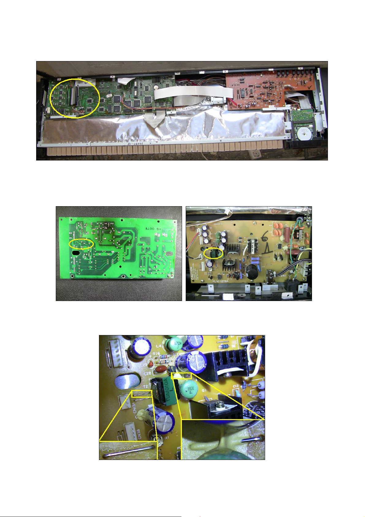
If you’ve done your homework correctly, you’ll end up with a board looking something like this:
Now on to the modification. You’ll work in the area marked in yellow above. First remove the two wire
jumpers as indicated on the pictures below:
Page 4

The one between the green coil and blue condenser might be difficult to extract due to the glue. I do not
advise using force here (the glue is meant to secure the coil and the condenser, so it is best left there),
rather cut the jumper making sure that a good length is removed to avoid accidental reconnection. This
cuts the supply to the 100V AC EL inverter, which ensures that the power capacity is given back to the
5V DC supply to provide power to the new display without overloading the PSU. The other jumper
(close to the white output connector) needs to be removed in order to ensure that no DC will flow back
through the 100V AC transformer’s secondary, causing unnecessary heating of the coil and as an even
worse side effect, draining of the available 5V DC current.
As the final step of the modification, a bit of the green solder lacquer has to be carefully removed,
scraped off the copper trace as indicated on the left hand side picture below. This is where we’ll tap the
5V DC source to provide supply to the LED backlight1. After removing the green solder mask you can
easily tin the trace and solder the handily available jumper you’ve just removed, between this point and
the disconnected pin of the backlight connector. This is indicated as No. 2 on the picture to the right, No.
1 marking the empty holes left by the removal of the other jumper.
When all this is done correctly, the black wire should be connected to the ground or negative pole of the
backlight on the new display (cathode – K), while the other wire (here in white) will be supplying the
+5V DC, as pictured below (you’ve noticed right, it was taken before the removal of the said jumper).
1
One might be irritated by the dimming backlight when the floppy drive operates. Tapping the 5V DC closer to the source
(i.e. from the coil after the heatsinked rectifying diode) might attenuate this problem – although I have not tried it yet and that
modification would be more obtrusive, riskier and trickier for the inexperienced, so not covered here.
Page 5
3. Post-trauma treatment
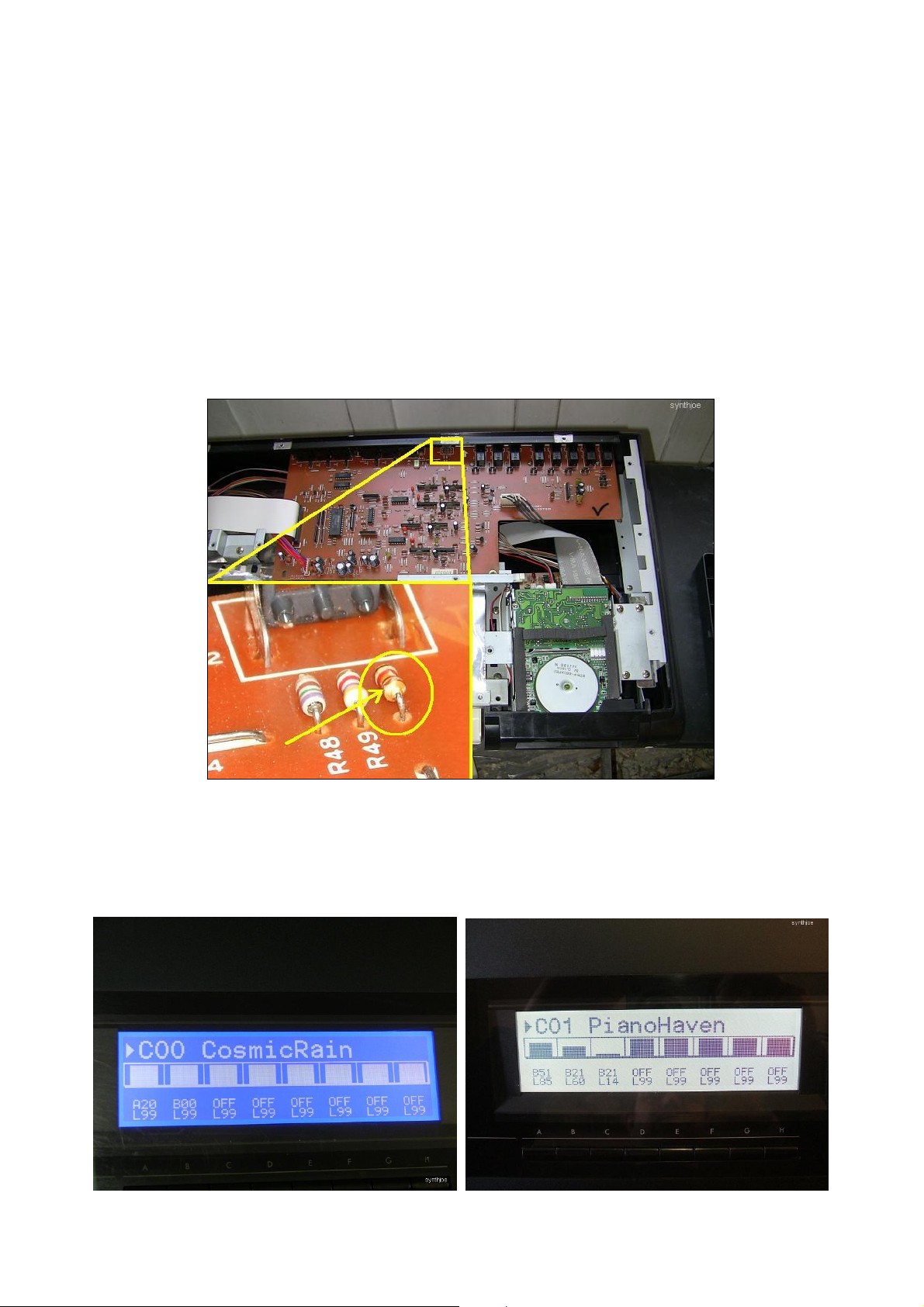
Some displays require different polarizing voltages than originally catered for in the T2. This results in a
completely blank (or dark, matter of consideration) display upon startup. First thing to try is to twist the
LCD contrast knob, as the solution might be as easy as this button moving out of alignment in the heat
of the job. If this does not cure the problem, but your synth does boot after the modification and makes
some noise on the outputs when playing the keyboard, you might have to install a resistor to redefine the
polarizing voltage. In one of the cases (the ‘cool blue’ display) I’ve handled the problem by adding a 1k
ohm resistor to the board pictured below (using the existing holes next to R49 in the vicinity of the
contrast knob), while in other cases no further modification was necessary. You might want to give it a
try, if staring at such a problem.
4. Enjoy!
Finally, if you’ve gotten tired of all this guide and want to scrap the whole idea of replacing the display,
here’s a little teaser of what you’ll get once putting yourself and your synth through all this trouble:
 Loading...