

Page 1

Page 2
Precautions
Location
Using the unit in the following locations can result in a malfunction.
• In direct sunlight
• Locations of extreme temperature or humidity
• Excessively dusty or dirty locations
• Locations of excessive vibration
• Close to magnetic fields
Power supply
Please connect the designated AC adapter to an AC outlet of
the correct voltage. Do not connect it to an AC outlet of voltage
other than that for which your unit is intended.
Interference with other electrical devices
Radios and televisions placed nearby may experience reception interference. Operate this unit at a suitable distance from
radios and televisions.
Handling
To avoid breakage, do not apply excessive force to the switches
or controls.
Care
If the exterior becomes dirty, wipe it with a clean, dry cloth. Do
not use liquid cleaners such as benzene or thinner, or cleaning
compounds or flammable polishes.
Keep this manual
After reading this manual, please keep it for later reference.
Keeping foreign matter out of your equipment
Never set any container with liquid in it near this equipment. If
liquid gets into the equipment, it could cause a breakdown, fire,
or electrical shock.
Be careful not to let metal objects get into the equipment. If
something does slip into the equipment, unplug the AC adapter
from the wall outlet. Then contact your nearest Korg dealer or
the store where the equipment was purchased.
IMPORTANT NOTICE TO CONSUMERS
This product has been manufactured according to strict specifications and voltage requirements that are applicable in the
country in which it is intended that this product should be
used. If you have purchased this product via the internet,
through mail order, and/or via a telephone sale, you must verify that this product is intended to be used in the country in
which you reside.
WARNING: Use of this product in any country other than that
for which it is intended could be dangerous and could invalidate the manufacturer’s or distributor’s warranty.
Please also retain your receipt as proof of purchase otherwise
your product may be disqualified from the manufacturer’s or
distributor’s warranty.
THE FCC REGULATION WARNING (for USA)
NOTE: This equipment has been tested and found to comply
with the limits for a Class B digital device, pursuant to Part 15
of the FCC Rules. These limits are designed to provide reasonable protection against harmful interference in a residential installation. This equipment generates, uses, and can radiate radio frequency energy and, if not installed and used in
accordance with the instructions, may cause harmful interference to radio communications. However, there is no guarantee that interference will not occur in a particular installation. If
this equipment does cause harmful interference to radio or
television reception, which can be determined by turning the
equipment off and on, the user is encouraged to try to correct
the interference by one or more of the following measures:
• Reorient or relocate the receiving antenna.
• Increase the separation between the equipment and receiver.
• Connect the equipment into an outlet on a circuit different
from that to which the receiver is connected.
• Consult the dealer or an experienced radio/TV technician for
help.
If items such as cables are included with this equipment, you
must use those included items.
Unauthorized changes or modification to this system can void
the user’s authority to operate this equipment.
DECLARATION OF CONFORMITY (for USA)
Responsible Party : KORG USA INC.
Address :
Telephone : 1-631-390-6500
Equipment Type : MONOPHONIC
Model : MS-20 Kit
This device complies with Part 15 of FCC Rules. Operation is
subject to the following two conditions:
(1) This device may not cause harmful interference,and (2)
this device must accept any interference received, including
interference that may cause undesired operation.
316 SOUTH SERVICE ROAD, MELVILLE, NY
SYNTHESIZER
Notice regarding disposal (for EU)
When this “crossed-out wheeled bin” symbol is displayed on the product, owner’s manual, battery, or battery package, it signifies that when you wish to dispose
of this product, manual, package or battery you must do
so in an approved manner. Do not discard this product,
manual, package or battery along with ordinary household waste. Disposing in the correct manner will prevent harm
to human health and potential damage to the environment.
Since the correct method of disposal will depend on the applicable laws and regulations in your locality, please contact
your local administrative body for details. If the battery contains heavy metals in excess of the regulated amount, a
chemical symbol is displayed below the “crossed-out wheeled
bin” symbol on the battery or battery package.
* All product names and company names are the trademarks or registered trademarks of their respective owners.
2
Page 3

Introduction
Thank you for purchasing the Korg MS-20 Kit Monophonic Synthesizer.
To ensure trouble-free enjoyment, please carefully read this
manual and use the product correctly. In addition, be sure to
store this manual in a safe place for future reference.
The MS-20 Kit is a reincarnation of the original MS-20, which
was released in 1978.
The MS-20 Kit uses analog circuitry to faithfully recreate the
sound and characteristics of this legendary instrument. We recommend reading the reprint of the original Owner’s Manual for
in depth descriptions of the various controls and their functions.
Since this manual contains additional information and details on
new functions, we recommend that you carefully read this manual together with the original Owner’s Manual.
* The original Owner’s Manual contains terms and phrases used
at the time of the original product release in 1978. The manual
may also contain information that differs from the MS-20 Kit or
may mention products that are no longer available. In addition,
the specifications contain details and measurement standards
from the time of the original MS-20 release, which differ from
those of the MS-20 Kit.
About the MS-20 Kit
The MS-20 Kit and the original MS-20 differ in the following
ways:
• Equipped with MIDI IN connector and USB port:
By connecting the MS-20 Kit to a computer, you can perform with it while using a sequencer.
• Equipped with earlier and later filters:
Different VCFs were installed in the earlier and later versions of the original MS-20. The MS-20 Kit is equipped with
both filters, which can be selected with a jumper wire on
the circuit board.
• AC adapter specifications:
Although the power supply has been changed to an AC
adapter, the internal voltage specifications are identical to
the original design.
Assembly
Precautions before assembly
Avoiding injuries while handling parts
Carefully handle the circuit boards to avoid injuries that could be
inadvertently caused by protruding parts. Protect your hands by
wearing (cotton) work gloves. In addition, be sure to wash your
hands with soap when finished with the assembly procedure.
Properly aligning screws and nuts before tightening
Tightening screws and nuts inserted at an angle may damage
the threading, preventing them from being fully tightened. Be
sure to align screws properly before tightening them.
In addition, be careful not to tighten screws with excessive force
or overtighten them, otherwise the parts may be damaged.
Preventing injuries and scratches to parts while using tools
When using tools to tighten screws and nuts, be careful to avoid
injuries, for example, to your fingers. In addition, carefully handle tools to avoid scratching panels, etc.
Provide a sufficiently large work space to complete the assembly procedure, and prepare work mats so parts will not be
scratched.
Preventing loss of screws and nuts
Carefully handle the included screws and nuts so they will not
be lost. In addition, do not use screws or nuts other than those
included for assembly, and do not use the included screws and
nuts for any other purpose.
TIP Extra screws and nuts are included. Use them as spares.
Tools to prepare
Phillips (+) screwdrivers: Use the screwdriver that’s appropriate for the size of the screw. Using a screwdriver of the wrong
size may damage the screw or may not properly tighten the
screw.
Box-end wrench (included): Use for tightening 11 mm and 12
mm hex nuts.
3
Page 4
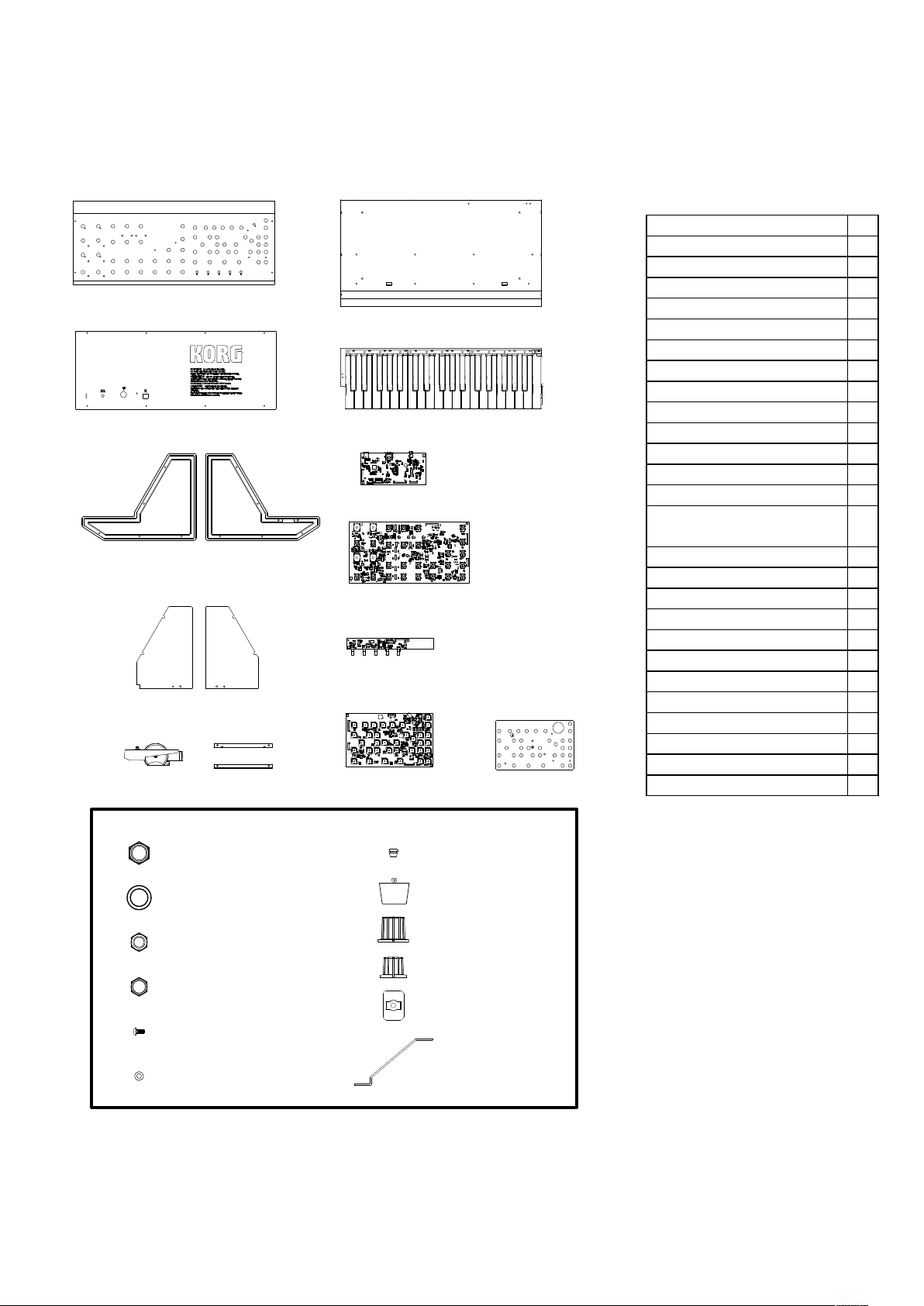
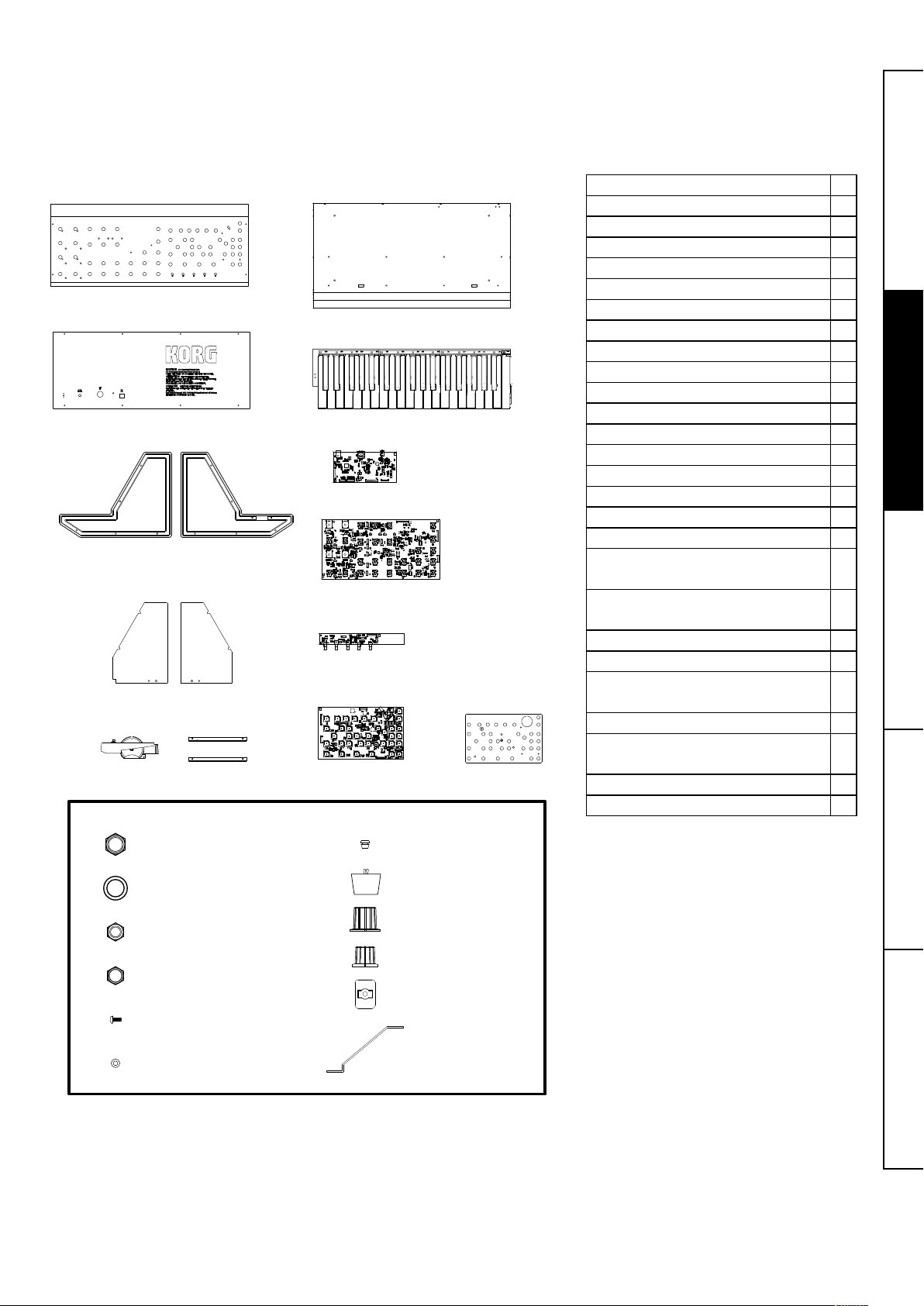
Checking package contents
Before beginning the assembly process, make sure that all of the parts are available.
If any part is missing or damaged, contact your local Korg distributor.
TIP More screws, nuts and washers than the number that will be used are included.
Front Panel
Rear Panel
Left side panelRight side panel
Left side shield Right side shield
Wheel unit
L -shaped bracket
Bottom Panel
keyboard unit
Rear jack circuit board unit
VR circuit board (large)
VR circuit board (small)
Panel jack circuit board
+ switch VR circuit board
Spacer Sheet
Front panel 1
Rear panel 1
Bottom panel 1
Left side panel 1
Right side panel 1
Left side shield 1
Right side shield 1
L-shaped bracket 2
Spacer sheet 1
Keyboard unit 1
Wheel unit 1
Rear jack circuit board unit 1
VR circuit board (large) 1
VR circuit board (small) 1
Panel jack circuit board &
switch VR circuit board
Nut (A): 12 mm hex 70
Washer (A) 35
Nut (B): 11 mm hex, VN 3BC7 6
Nut (C): 11 mm hex, VN 3BC9 30
Screw: FE B 3BBC 3X8 36
Washer [B]: WK 3BBC 3 13
Knob (large) 7
Knob (small) 29
Rubber bushing 10
Rubber feet 4
Cord hook 1
Box-end wrench (included) 1
1
Nut (A)
Washer (A)
Rubber bushing
Rubber feet
Knob (large)
Nut (B): VN 3BC 7
Knob (Small)
Nut (C): VN 3BC 9
Cord hook
Screw: FE B 3BBC 3x8
Box-end wrench
Washer (B): WK 3BBC 3
4
Page 5
Assembling the bottom panel section
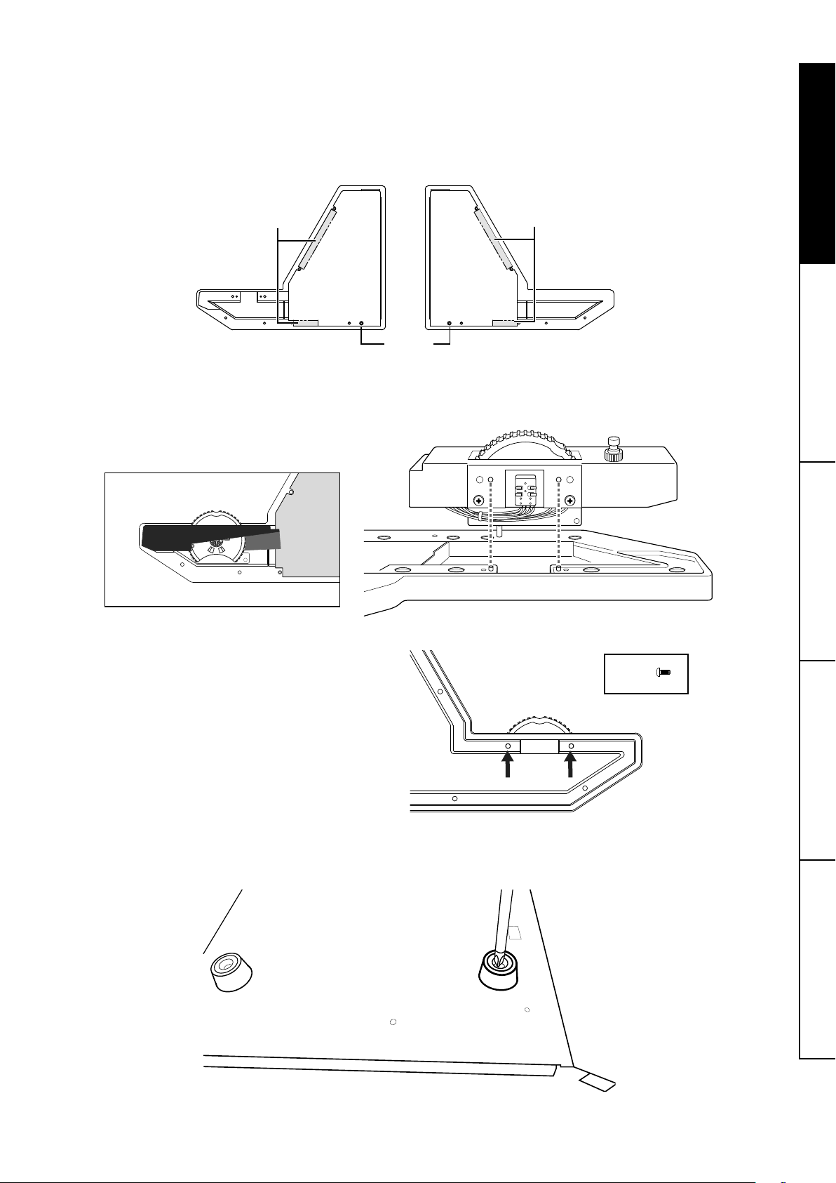
1. Affixing the side shields
Affix the left side shield to the left side panel.
Peel the backing paper from the double-sided tape on the shield, and then use the guide pins on the side panel as reference to
affix the shield so that it does not extend from the panel.
Affix the right side shield to the right side panel in the same way.
double-sided tape
guide pin
double-sided tape
2. Attaching the wheel unit to the left side panel with screws
Using the guides as a reference, install the wheel unit, and then secure it with the two screws.
Caution: Be careful not to pinch the cable during this process .
Screw
3. Attaching the rubber feet to the bottom panel
Install the rubber feet in the four locations on the bottom panel. Insert the rubber feet into the installation holes in the bottom
panel, and then insert the tip of the screwdriver into the center of the rubber feet and secure them.
Caution: Be careful to avoid injuries from the tip of the screwdriver.
5
Page 6
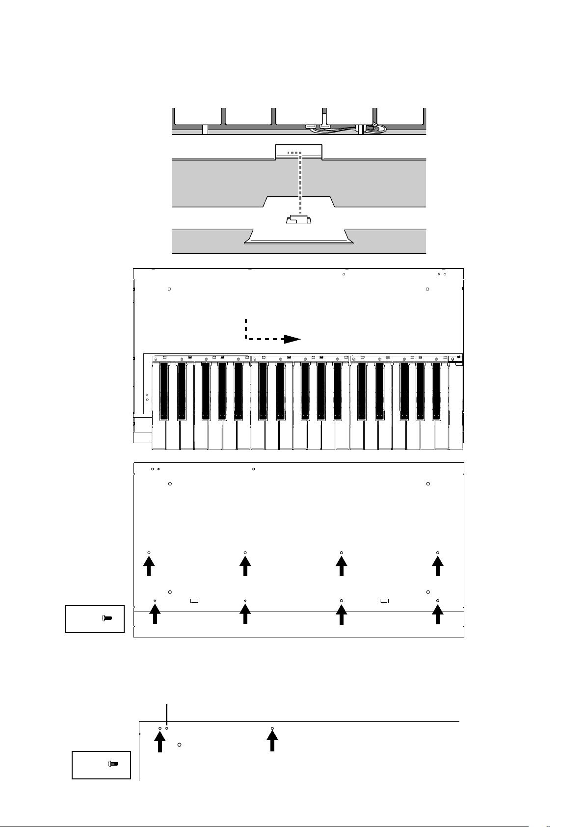
4. Attaching the keyboard unit to the bottom panel with screws
guide
Place the keyboard on the bottom panel with the mounting tabs on the bottom panel aligned with the two cutouts on the keyboard. After sliding the positioned keyboard forward, then to the right, secure it in place with the eight screws from the back of
the bottom panel while making sure that the keyboard does not shift.
Caution: Be careful not to pinch the wire harnesses during this process.
Screw
5. Attaching the rear jack circuit board unit to the bottom panel with the included screws
Position the rear jack circuit board unit with its guide tabs aligned with the positioning holes on the bottom panel, and then secure
with two screws.
Screw
6
Page 7
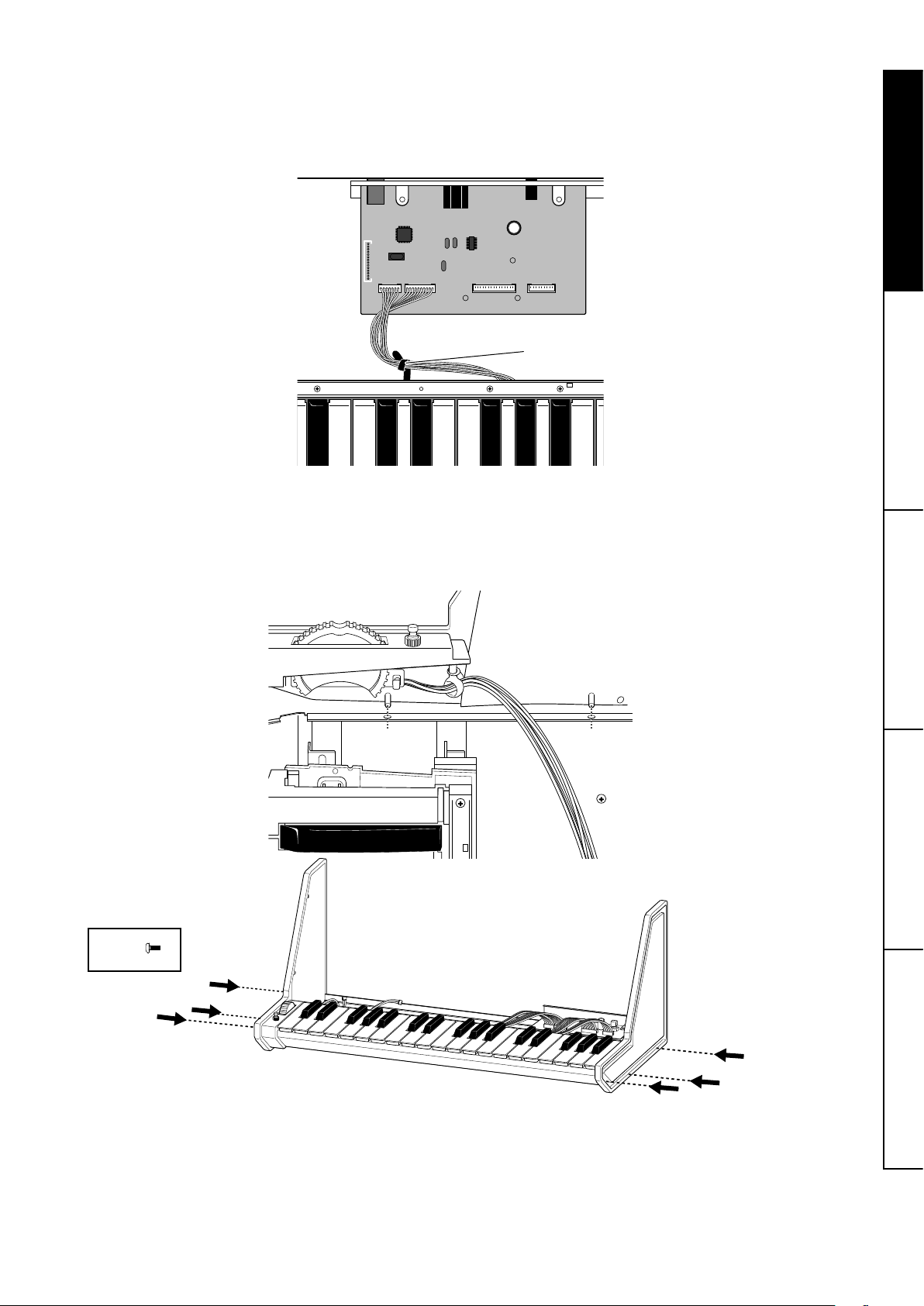
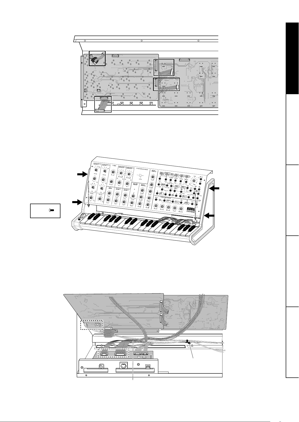
6. Connecting the keyboard cable to the rear jack circuit board unit
After twisting the keyboard wire harnesses together several times, plug them into the appropriate connectors on the rear jack
circuit board, making sure of the correct orientation.
Secure the connected wire harnesses with the clips attached to the keyboard.
Caution: When making connections, hold the circuit board to firmly insert the connectors.
clips
7. Attaching the left side panel section to the bottom panel with screws
Install the left side panel section, assembled in step 2, with its two guide pins aligned with the positioning holes on the bottom
panel, and then secure it with three screws.
Install the right side panel section in the same way, and then secure it with three screws.
Caution: Be careful not to pinch the wire harnesses during this process.
Screw
7
Page 8
Assembling the front panel section
1. Mounting the rubber bushings on the front panel
Install the rubber bushings in the ten locations on the front panel.
Caution: Make sure that the installation locations are correct.
rubber bushings
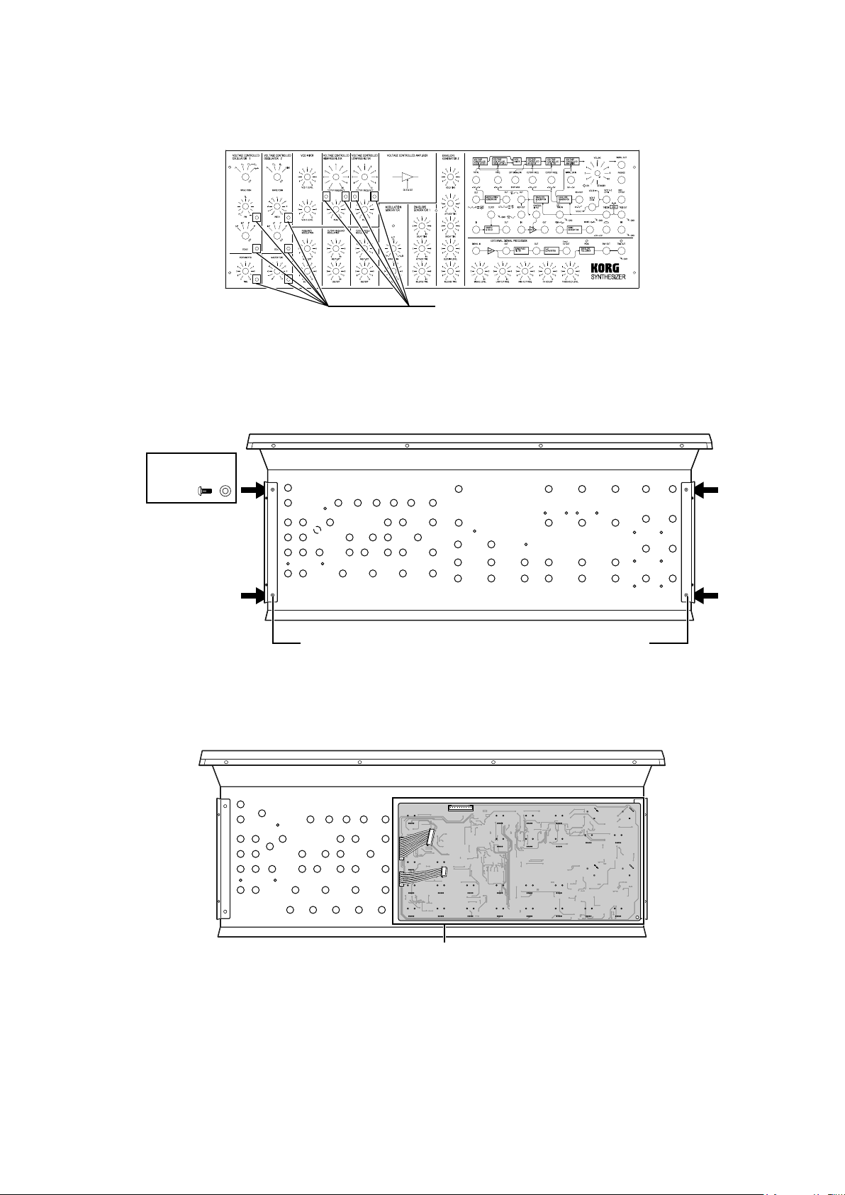
2. Attaching the L-shaped brackets to the left and right sides at the rear of the front panel with the
included screws and washers (B)
Align the screw holes on the front panel and the L-shaped bracket, and then secure it with the two screws and washers (B).
Complete the installation on the left and right sides in the same way. There is no difference between the left and right L-shaped
brackets.
Washer (B)
Screw
L-shaped bracket L-shaped bracket
3. Attaching the VR circuit board (large) to the front panel with the included nuts (C)
Caution: Be careful to avoid injuries to your hands from the terminals.
Caution: Be careful that the panel is not scratched when the included box-end wrench is used to tighten the nuts.
Caution: If the nuts are overtightened, the controls may not move smoothly.
VR circuit board (large)
8
Page 9
Nut (C)
Verify that the LEDs
fit through the front
panel.
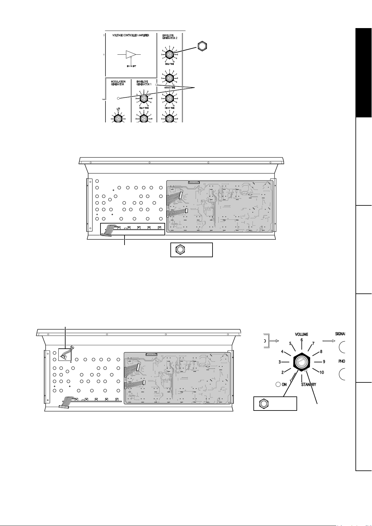
4. Attaching the VR circuit board (small) to the front panel with the included nuts (B)
Caution: Be careful to avoid injuries to your hands from the terminals.
Caution: Be careful that the panel is not scratched when the included box-end wrench is used to tighten the nuts.
VR circuit board (small)
Nut (B)
5. Attaching the switch VR circuit board to the front panel with the included nuts (B)
Disconnect the wiring harness (to be connected to the panel jack circuit board) from the switch VR circuit board, and then attach
the switch VR circuit board to the front panel.
Make sure that the orientation is correct by aligning the guide pins with the guide holes on the panel, and then secure it with the
included nuts.
Caution: Be careful that the panel is not scratched when the included box-end wrench is used to tighten the nuts
switch VR circuit board
Nut (B)
guide pin
9
Page 10
6. Installing the spacer sheet on the panel jack circuit board
Make sure that the three LEDs are correctly positioned, and then install the spacer sheet.
Secure all of the jacks with the included nuts (A).
Caution: Be sure to firmly tighten the nuts so the spacer sheet does not move out of place.
Caution: Be careful that the LEDs are not scratched with the tools.
Nut (A)
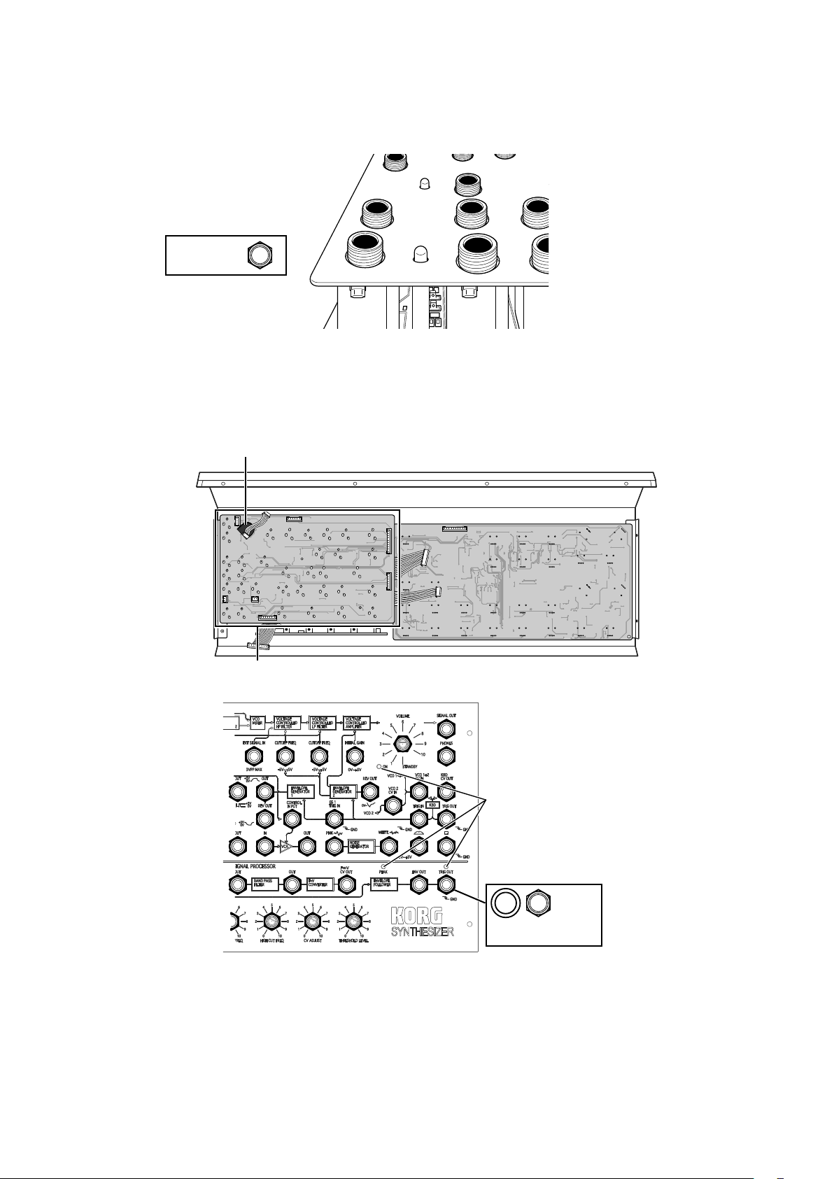
7. Attaching the panel jack circuit board to the front panel with the included washers (A) and nuts
(A)
Caution: Be careful to avoid injuries to your hands from the terminals.
Caution: Be careful that the panel is not scratched when the included box-end wrench is used to tighten the nuts.
Feed the wiring harness for the switch VR
circuit board through the hole.
Panel jack circuit board
Verify that the LEDs
fit through the front
panel.
Nut (A)
Washer (A)
10
Page 11
8. Feeding the wiring harnesses to the panel jack circuit board
Plug in the four wiring harnesses, making sure that the orientation is correct.
Assembling the bottom panel section and the front panel section
1. Attaching the front panel section to the bottom panel section with the included screws
While making sure that the shields on both sides do not bend, place the front panel on top of the bottom panel, and then slide
the front panel down against the keyboard.
Screw
2. Plugging all wiring harnesses into their connectors
Plug in the four wiring harnesses, making sure to observe the correct orientation.
After twisting the wiring harnesses of the VR circuit board and panel jack circuit board together several times, plug them into the
connectors on the rear jack circuit board.
Make sure to secure the cable from the wheel unit with clips so that it is not loose.
Caution: When making connections, hold the circuit board to firmly insert the connectors.
clips
After twisting the wiring harnesses of the VR circuit board and
panel jack circuit board together several times, plug them into
the connectors on the rear jack circuit board.
11
Page 12
clips
Make sure to secure the cable from the wheel unit
with clips so that it is not loose.
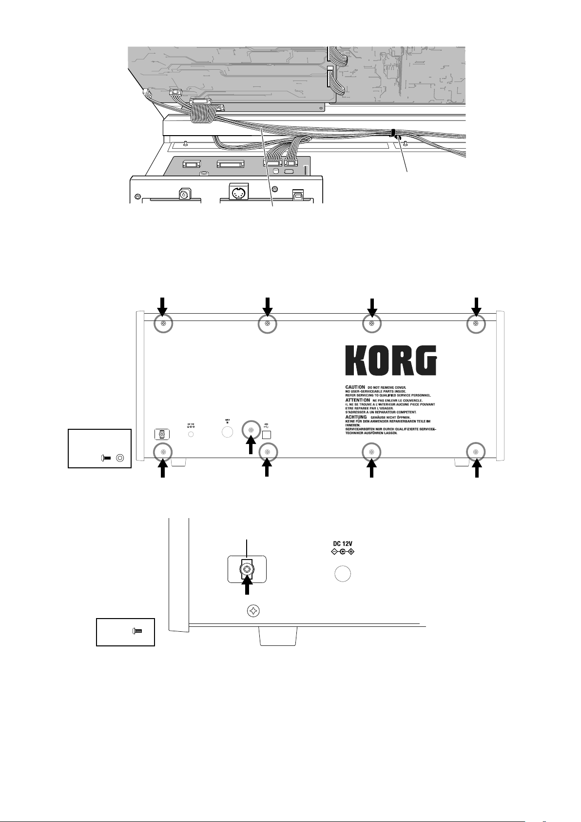
3. Attaching the rear panel with the included screws and washers (B)
Attach the rear panel, aligning it with the DC12V jack, and then secure it at the nine screw locations using the included screws
and washers(B).
Before attaching the rear panel, make sure that all wiring harnesses are connected.
Washer (B)
Screw
4. Attaching the cord hook
Attach the cord hook near the DC12V jack with the included screws.
cord hook
Screw
12
Page 13
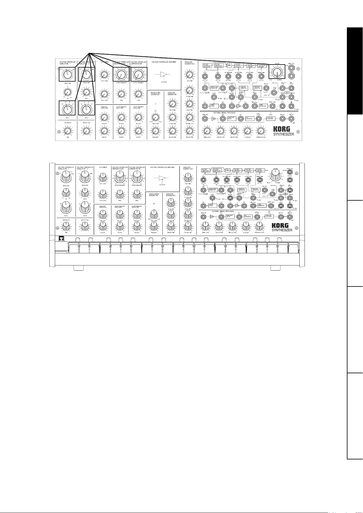
5. Placing the knobs onto the VR shafts
Make sure that the knob size and orientation are correct.
Install the knobs (large) at the locations shown below.
6. Congratulations, the assembly is complete!
13
Page 14
Confirming functionality
After assembling all of the parts, make sure that there are no
parts remaining, and then follow the entire assembly procedure
in this assembly manual to confirm that the device has been
correctly assembled.
If this device has been correctly assembled, follow the procedures in “Basic Operation” (p. 15) to confirm its functionality.
If a problem has been found in the assembly or functionality ,
follow the troubleshooting procedure that’s described below to
resolve the problem.
Assembly troubleshooting
• Extra parts remaining
→ More screws, nuts and washers than the number that
will be used are included.
→ If there are any other parts remaining, return to the
step where those parts were used and correctly perform the assembly procedure.
• Parts missing
→ If any parts are missing, contact your local Korg dis-
tributor.
→ If any parts are damaged or missing before beginning
the assembly procedure, contact your local Korg distributor.
• Cannot be assembled. Parts are damaged.
→ Contact your local Korg distributor.
• After being assembled, the device produces a strange
noise if it is tilted or shaken.
→ There may be a loose screw or some other loose part
within the device. Open the rear panel and check inside the device.
• The controls or jacks are loose.
→ Remove the knob, and then firmly tighten the nut.
Troubleshooting
If any control does not function even though it has been set, a
faulty cable connection may have occurred during assembly.
Check the appropriate cable according to the symptom.
• The device does not turn on.
→ Is the 9-pin red wire harness or 5-pin purple wire harness dis-
connected?
• No sound is produced from the headphones.
→ Is the 13-pin orange wire harness or 8-pin yellow wire harness
disconnected?
• No sound is produced when a keyboard key is pressed.
→ Is the 10-pin blue wire harness or 7-pin grey wire harness
disconnected?
• The device is turned on, but the MODULATION GENERA-
TOR LED does not blink.
→ Is the 15-pin brown wire harness disconnected?
• The controls in the EXTERNAL SIGNAL PROCESSOR
section do not work.
→ Is the 12-pin green wire harness disconnected?
• Buttons do not function when pressed.
→ Is the 2-pin blue/green wire harness disconnected?
• The control wheel does not function when adjusted.
→ Is the 4-pin brown/red/orange/yellow wire harness discon-
nected?
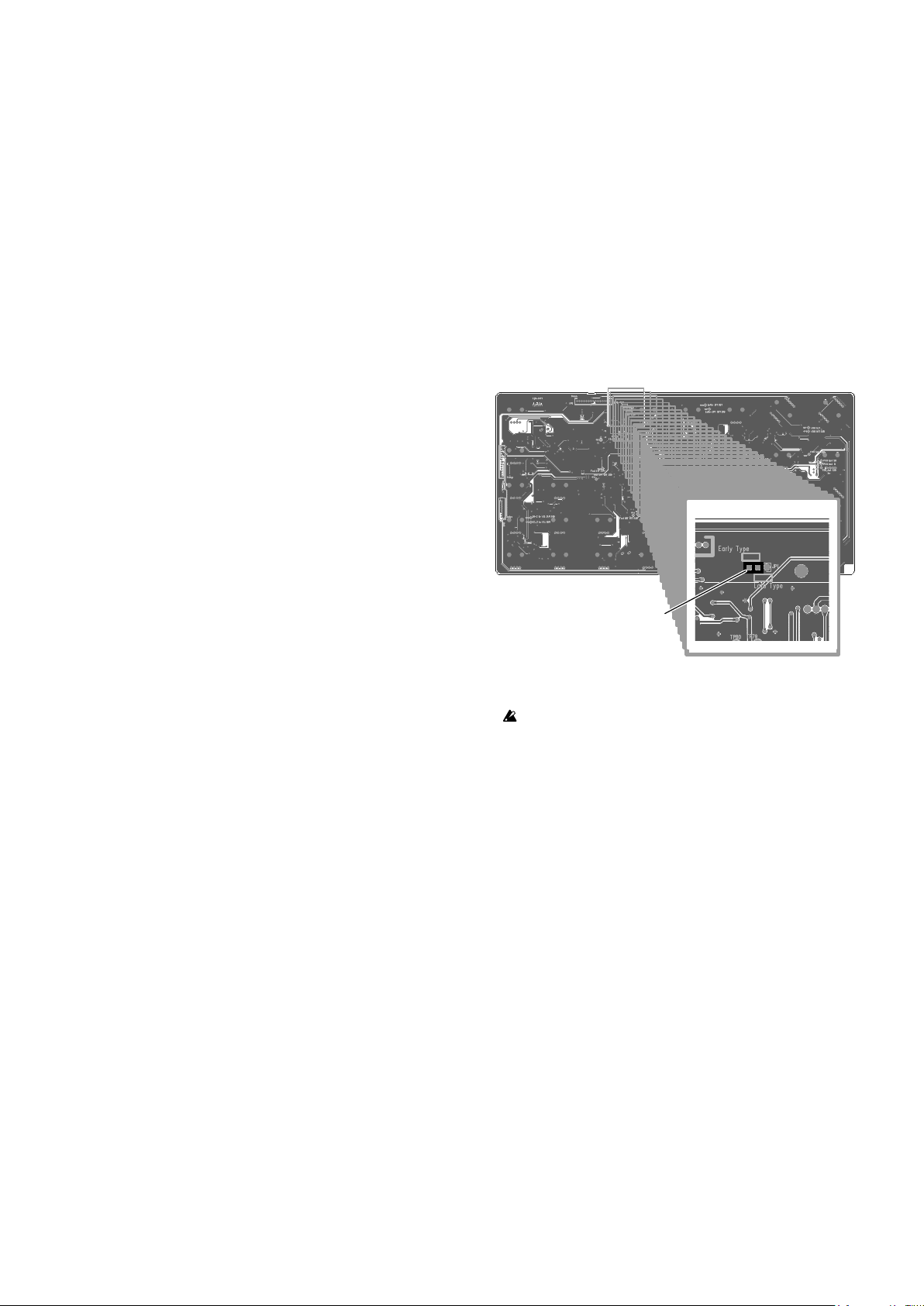
VCF setting
The VCFs (high-pass filter & low-pass filter) of the original MS20 are differentiated into the earlier and later filters, depending
on the production date.
Since the circuitry of these two types of filters differs, they have
different sound quality characteristics, although their frequency
characteristics are similar.
The MS-20 Kit is equipped with both types of filters for you to
select as desired.
Setting procedure
Insert the short pin into the 3-pin header on the back of the VR
circuit board (large).
When the short pin is inserted into the later filter (late type), the
later filter is set.
VR circuit board (large)
short pin
TIP As the factory default, the short pin is set to the earlier filter
(early type).
Before switching the short pin, be sure to turn off the MS-20.
Quick selection
To compare the sound of the originally installed filter with the
other filter, temporarily change the setting as described below.
• To select the earlier filter, hold down the F#3, G#3 and A#3
keys and turn on the MS-20.
• To select the later filter, hold down the F#3, G#3 and B3
keys and turn on the MS-20.
TIP No matter which filter is set with the above operations, the set-
ting will revert to the filter set with the short pin on the circuit
board when the MS-20 is turned off.
14
Page 15
Basic Operation
powered monitor
1. Connections
Make sure each device is turned off before connecting any add
itional equipment. If an operation is inadvertently performed, the
speaker system and other devices may be damaged or malfunction.
1. Connecting the AC adapter
Connect the included AC adapter to the DC12V jack.
Only use the included AC adapter.
2. Connecting the amp
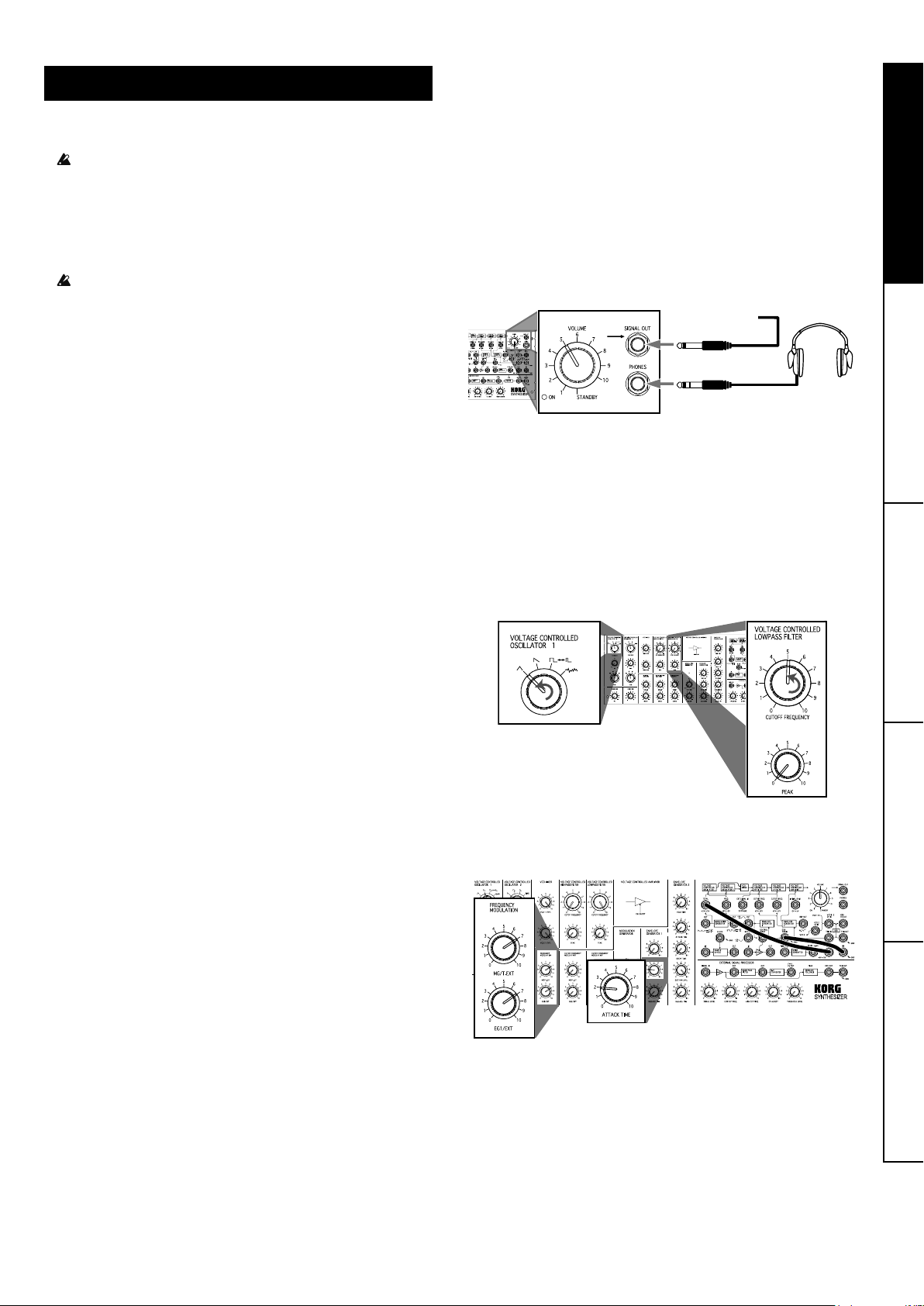
Connect the powered monitor speaker or mixer to the SIGNAL OUT jack.
3. Connecting headphones
When using headphones, insert the headphone plug into
the PHONES jack.
4. Connecting guitars and microphones to the SIGNAL IN
jack
When using an external signal processor, connect the guitar or microphone to the SIGNAL IN jack.
For details, refer to “Using the External Signal Processor
(ESP)” in the original Owner’s Manual.
2. Turning on the device
1. Turn the VOLUME knob clockwise.
2. After a click, the STANDBY ON LED lights up and the de-
vice is turned on.
TIP If the auto power off function is disabled, the LED blinks a few
times.
3. To turn off the device, turn the VOLUME knob counter-
clockwise until it clicks and the LED turns off.
TIP If the AC adapter is disconnected while the MS-20 Kit is turned
on or if the auto power off function has been enabled, the device
may have turned off without the VOLUME knob in the off position. Before turning on the MS-20 Kit again, you’ll have to turn
the VOLUME knob counterclockwise to turn it off.
To enable the auto power off function again
While holding down C1, D1 and F1 on the keyboard, turn
on the MS-20 Kit.
The STANDBY ON LED lights up, without blinking, and
then the device returns to normal operation.
3. Producing sounds
Basic settings
Refer to “Normal Setting” (→p. 76 ) and adjust the knobs.
Producing sounds by playing the keyboard
Press a keyboard key to hear the tone.
speaker, mixer
To adjust the volume, turn the VOLUME knob.
TIP Even if multiple keyboard keys are pressed, only one tone will be
produced. When two or more keys are pressed, the highest tone
played will be produced.
Adjusting the knobs
Turn the CUTOFF FREQUENCY knob of the LOWPASS FILTER counterclockwise to round off the sound. In addition, adjust
the timbre by using the OSCILLATOR 1 knob to change the
waveform to the triangle wave.
Auto power off function
1. The MS-20 Kit is automatically turned off if none of the fol-
lowing operations are performed for 4 hours.
Sound is produced with the keyboard; Note On via MIDI IN
or USB MIDI; input to TRIG IN
2.
When turning on the MS-20 Kit again, turn the VOLUME knob
counterclockwise to turn it off, and then turn on the device.
TIP The auto power off function is enabled as a factory setting (de-
fault.)
To disable the auto power off function
While holding down C1, D1 and E1 on the keyboard, turn
on the MS-20 Kit.
After the STANDBY ON LED blinks a few times, it remains
lit, and then the device returns to normal operation.
TIP
The setting for the auto power off function is saved, even if the MS20 Kit is turned off.
TIP When changing the setting, do not turn off the device before the
STANDBY ON LED lights up. Otherwise, data may be corrupted
or the device may be damaged.
Patching to add variations to timbre
Refer to the following illustration and connect the patch cables.
The control wheel and momentary switch can be used. Adjust
the control wheel and momentary switchs, and listen to the variations in the timbre.
Refer to the original Owner’s Manual and the setting chart to
create various sounds.
15
Page 16

4. About MIDI
The MIDI IN connector and USB port on the MS-20 Kit are some
of the main differences between it and the original MS-20.
By connecting the MS-20 Kit to a computer, you can perform
with it while using a sequencer.
Connecting MIDI devices
In order to transmit/receive MIDI information, you can use commercially available MIDI cables. Connect the MIDI connector of
the MS-20 Kit to the MIDI connector of the external MIDI device
where information will be exchanged.
MIDI IN connector: This receives MIDI messages from other
MIDI devices. This should be connected to the MIDI OUT connector of the other device.
The only MIDI messages that can be received at the MIDI IN
connector are note messages (Velocity is disabled) on MIDI
channel 1 (fixed).
TIP If a Note On message with a note number of 92 or more is re-
ceived, the message will become invalid, and the sound being
produced will stop. It will also be invalid if a note number is 11 or
less; however, the sound will continue to be produced.
Connecting a computer
Use a USB cable to directly connect the MS-20 Kit to a computer equipped with a USB port in order to receive MIDI messages in the same way as with the MIDI connectors.
The only MIDI messages that can be transmitted and received
at the USB port are note messages (Velocity is transmitted fixed
at 64 and reception is disabled) on MIDI channel 1 (fixed).
TIP The only MIDI messages that are transmitted are note messag-
es transmitted when the keyboard is played. Messages, for example, for pitch bend and modulation, will not be transmitted.
TIP When connecting via USB, the KORG USB-MIDI driver must be
installed. Download the KORG USB-MIDI driver from the Korg
Web site ( http://www.korg.co.jp/English/Distributors/ or http://
www.korg.com/ ), and then install it according to the instructions
in the document included with the driver.
Specifications
Keyboard: 37 Keys (3 octaves)
Controllers: Control wheel (center click), Momentary
switch (
Connectors: SIGNAL IN jack (1/4" phone jack), SIG-
NAL OUT jack (1/4" phone jack, 2Vp-p
output impedance 3.5kΩ), PHONES jack
(1/4" Stereo phone jack, 33Ω 48mW),
DC12V jack, MIDI IN, USB typeB
Power supply:
Dimensions: 573 mm (W) x 316 mm (D) x 248 mm (H)
Weight: 6.3 kg / 13.89 lbs.
Included items: 10x Patch cord, AC adapter ( , 12V)
* Specifications and appearance are subject to change without notice for improvement.
DC12V
/ 22.56" (W) x 12.44" (D) x 9.76" (H)
)
About the MIDI implementation chart
The MIDI implementation chart lists the MIDI messages that
can be transmitted and received. When using a MIDI device,
compare the MIDI implementation charts to check that the MIDI
messages are compatible.
TIP Detailed MIDI specifications are provided under MIDI implemen-
tation. For more information on MIDI implementation, visit the
Korg Web site ( http://www.korg.co.jp/English/Distributors/ or
http://www.korg.com/ ).
16
Page 17
Précautions
Emplacement
L’utilisation de cet instrument dans les endroits suivants peut en
entraîner le mauvais fonctionnement.
• En plein soleil
• Endroits très chauds ou très humides
• Endroits sales ou fort poussiéreux
• Endroits soumis à de fortes vibrations
• A proximité de champs magnétiques
Alimentation
Branchez l’adaptateur secteur mentionné à une prise secteur
de tension appropriée. Evitez de brancher l’adaptateur à une
prise de courant dont la tension ne correspond pas à celle pour
laquelle l’appareil est conçu.
Note concernant les dispositions (Seulement EU)
Quand un symbole avec une poubelle barrée d’une
croix apparait sur le produit, le mode d’emploi, les piles
ou le pack de piles, cela signifie que ce produit, manuel
ou piles doit être déposé chez un représentant compétent, et non pas dans une poubelle ou toute autre dé-
chetterie conventionnelle. Disposer de cette manière,
de prévenir les dommages pour la santé humaine et les dommages potentiels pour l’environnement. La bonne méthode
d’élimination dépendra des lois et règlements applicables
dans votre localité, s’il vous plaît, contactez votre organisme
administratif pour plus de détails. Si la pile contient des métaux lourds au-delà du seuil réglementé, un symbole chimique
est affiché en dessous du symbole de la poubelle barrée
d’une croix sur la pile ou le pack de piles.
Interférences avec d’autres appareils électriques
Les postes de radio et de télévision situés à proximité peuvent
par conséquent souffrir d’interférences à la réception. Veuillez
dès lors faire fonctionner cet appareil à une distance raisonnable de postes de radio et de télévision.
Maniement
Pour éviter de les endommager, manipulez les commandes et
les boutons de cet instrument avec soin.
Entretien
Lorsque l’instrument se salit, nettoyez-le avec un chiffon propre
et sec. Ne vous servez pas d’agents de nettoyage liquides tels
que du benzène ou du diluant, voire des produits inflammables.
Conservez ce manuel
Après avoir lu ce manuel, veuillez le conserver soigneusement
pour toute référence ultérieure.
Evitez toute intrusion d’objets ou de liquide
Ne placez jamais de récipient contenant du liquide près de l’instrument. Si le liquide se renverse ou coule, il risque de provoquer des dommages, un court-circuit ou une électrocution.
Veillez à ne pas laisser tomber des objets métalliques dans le
boîtier (trombones, par ex.). Si cela se produit, débranchez l’alimentation de la prise de courant et contactez votre revendeur
korg le plus proche ou la surface où vous avez acheté l’instrument.
REMARQUE IMPORTANTE POUR LES CLIENTS
Ce produit a été fabriqué suivant des spécifications sévères et
des besoins en tension applicables dans le pays où ce produit
doit être utilisé. Si vous avez acheté ce produit via l’internet,
par vente par correspondance ou/et vente par téléphone,
vous devez vérifier que ce produit est bien utilisable dans le
pays où vous résidez.
ATTENTION: L’utilisation de ce produit dans un pays autre
que celui pour lequel il a été conçu peut être dangereuse et
annulera la garantie du fabricant ou du distributeur. Conservez bien votre récépissé qui est la preuve de votre achat,
faute de quoi votre produit ne risque de ne plus être couvert
par la garantie du fabricant ou du distributeur.
* Tous les noms de produits et de sociétés sont des marques commerciales ou
déposées de leur détenteur respectif.
17
Page 18

Avant-propos
Nous vous remercions d’avoir choisi le synthétiseur monophonique MS-20 Kit de Korg.
Pour garantir une utilisation sans problème de l’instrument,
veuillez lire attentivement ce manuel et manipuler le produit de
façon correcte. Veillez en outre à conserver ce manuel en lieu
sûr pour pouvoir le consulter à tout moment.
Le MS-20 Kit est la réincarnation du MS-20 original, dévoilé au
public en 1978.
Le MS-20 Kit est doté de circuits analogiques qui permettent de
recréer fidèlement le son et les caractéristiques de cet instrument légendaire. Nous vous conseillons vivement de lire la reproduction du Mode d’emploi de l’instrument original; vous y
trouverez une description complète des diverses commandes
et de leurs fonctions.
Vu que le présent manuel contient des informations complémentaires et des détails au sujet des nouvelles fonctions, lisezle attentivement en plus du mode d’emploi original.
* Le mode d’emploi original contient des termes et tournures utilisés au moment
de la sortie de l’instrument original en 1978. Ce manuel pourrait en outre contenir des informations qui ne correspondent pas au MS-20 Kit ou mentionner des
produ its qui ne sont plus disponibles. Notez encore que les détails et normes
de mesure figurant dans les caractéristiques techniques de l’instrument sont
ceux employés à la sortie du MS-20 original, et qu’ils diffèrent de ceux du MS20 Kit.
A propos du MS-20 Kit
Voici les différences entre le MS-20 Kit et le MS-20 original.
Comporte une prise MIDI IN et un port USB: Vous pouvez
brancher le MS-20 Kit à un ordinateur et jouer sur l’instrument
accompagné d’un séquenceur.
Équipé des filtres anciens et récents : Plusieurs VCF ont été
installés dans les versions anciennes et récentes du MS-20
d’origine. Le MS-20 kit est équipé des deux types de filtres, qui
peuvent être sélectionnés avec un fil de raccordement sur la
carte du circuit.
Caractéristiques de l’adaptateur secteur: Bien que l’alimentation soit passée à un adaptateur secteur, les caractéristiques
de tension interne sont identiques à celles de l’instrument original.
Assemblage
Précautions avant l’assemblage
Éviter les blessures lors de la manipulation de pièces
Maniez les cartes des circuits avec soin pour éviter les blessures qui pourraient être causées par accident par des pièces
protubérantes. Protégez vos mains en portant des gants de travail (en coton). De plus, veillez à laver vos mains avec du savon
lorsque vous avez terminé la procédure d’assemblage.
Aligner correctement les vis et les écrous avant le serrage
Le serrage des vis et des écrous en angle peut endommager
l’enfilage, ce qui peut les empêcher d’être complètement serrés. Veillez à aligner les vis correctement avant de les serrer.
De plus, faites attention à ne pas serrer les vis en exerçant une
force excessive et à ne pas trop les serrer, car les pièces pourraient être endommagées.
Éviter les blessures et la rayure des pièces lors de l’utilisation d’outils
Lorsque vous utilisez des outils pour serrer des vis et écrous,
faites attention à éviter les blessures, à vos doigts notamment.
De plus, maniez les outils avec soin pour éviter de rayer les
panneaux, etc.
Organisez un espace de travail suffisant pour effectuer la procédure d’assemblage, et préparez des tapis de travail pour ne pas
rayer les pièces.
Éviter de perdre les vis et écrous
Maniez les vis et écrous fournis avec soin afin de ne pas les
perdre. De plus, n’utilisez pas d’autres vis et écrous que ceux
fournis pour l’assemblage, et n’utilisez pas les vis et écrous
fournis à d’autres fins.
ASTUCE Des vis et écrous supplémentaires sont fournis. Utilisezles en cas de besoin de remplacement.
Outils à préparer
Tournevis Phillips (+) : Utilisez le tournevis convenant à la
taille de la vis. Utiliser un tournevis de la mauvaise taille pourrait
endommager la vis ou vous empêcher de bien la serrer.
Clé polygonale (fournie) : Utilisez-la pour serrer les écrous
hexagonaux de 11 mm et 12 mm.
18
Page 19
Vérifier le contenu de l’emballage
Avant de démarrer le processus d’assemblage, vérifiez que toutes les pièces sont présentes.
Si des pièces manquent ou sont endommagées, contactez votre distributeur Korg local.
ASTUCE Vous trouverez plus de vis, écrous et joints inclus que nécessaire pour l’assemblage.
Panneau avant
Panneau arrière
Panneau latéral gauchePanneau latéral droit
Protection latérale gauche Protection latérale droite
Unité de la roue
Crochet en L
Panneau inférieur
Unité du clavier
Unité de la carte du circuit de la prise arrière
Carte du circuit VR (grande)
Carte du circuit VR (petite)
Carte du circuit du panneau droit et
carte du circuit VR de l’interrupter
Feuille d’espacement
Panneau avant 1
Panneau arrière 1
Panneau inférieur 1
Crochet en L 2
Panneau latéral gauche 1
Panneau latéral droit 1
Protection latérale gauche 1
Protection latérale droite 1
Feuille d’espacement 1
Commande (grande) 7
Commande (petite) 29
Manchon de caoutchouc 10
Pieds en caoutchouc 4
Crochet de cordon 1
Écrou (A): hexagonaux de 12 mm 70
Joint (A) 35
Vis: FE B 3BBC 3X8 36
Joint (B): WK 3BBC 3 13
Écrou (B): hexagonaux de 11 mm, VN
3BC7
Écrou (C): hexagonaux de 11 mm, VN
3BC9
Unité du clavier 1
Unité de la roue 1
Unité de la carte du circuit de la prise
arrière
carte du circuit VR (petite) 1
Carte du circuit du panneau droit et
carte du circuit VR de l’interrupteur
Carte du circuit VR (grande) 1
Clé polygonale (fournie) 1
30
6
1
1
Écrou (A)
Joint (A)
Écrou (B): VN 3BC 7
Écrou (C): VN 3BC 9
Vis: FE B 3BBC 3x8
Joint (B): WK 3BBC 3
Manchon de caoutchouc
Pieds en caoutchouc
Commande (grande)
Commande (petite)
Crochet de cordon
Clé polygonale
19
Page 20

Assembler la section du panneau inférieur
1. Fixer les protections latérales
Fixez la protection latérale gauche sur le panneau
latéral gauche.
Retirez le papier de soutien du ruban adhésif
double-face, puis utilisez les broches de guidage
sur le panneau latéral comme référence pour fixer
la protection afin qu’elle ne sorte pas du panneau.
Fixez la protection sur le panneau latéral droit de
la même façon.
2. Fixer l’unité de roue sur le panneau latéral gauche avec des vis
Utilisez les guides comme référence, installez l’unité de roue puis fixez-la avec les deux vis.
Attention: Veillez à ne pas pincer le câble lors de ce processus.
ruban adhésif double-face ruban adhésif double-face
broche de guidage
3. Fixer les pieds en caoutchouc sur le panneau inférieur
Installez les pieds en caoutchouc aux quatre emplacements du panneau inférieur. Insérez les pieds en
caoutchouc dans les trous d’installation du panneau
inférieur, puis insérez l’extrémité du tournevis dans le
centre des pieds en caoutchouc et fixez-les.
Attention: Veillez à ne pas vous blesser avec la
pointe du tournevis.
Vis
20
Page 21

4. Fixer l’unité du clavier sur le panneau inférieur avec des vis
guide
Placez le clavier sur le panneau inférieur en alignant les pattes de montage sur le panneau inférieur avec les deux trous du clavier.
Après avoir fait glisser le clavier positionné d’abord vers l’avant, puis sur la droite, fixez-le avec les huit vis de l’arrière du panneau
inférieur tout en veillant à ce que le clavier ne se décale pas.
Attention : Veillez à ne pas pincer les faisceaux de fils lors de ce processus.
Vis
5. Fixer l’unité de carte du circuit de la prise arrière au panneau inférieur avec les vis fournies
Positionnez l’unité de carte du circuit de la prise arrière en alignant ses pattes de guidage avec les trous de positionnement du
panneau inférieur, puis fixez avec deux vis.
Vis
21
Page 22

6. Connecter le câble du clavier à l’unité de carte du circuit de la prise arrière
Après avoir torsadé les faisceaux de fils ensemble plusieurs fois, branchez-les sur les bons connecteurs de la carte du circuit de
la prise arrière, en veillant à respecter l’orientation.
Fixez les faisceaux de fils branchés avec les pinces fixées sur le clavier.
Attention : Tenez la carte de circuit pour insérer les connecteurs fermement lorsque vous effectuez des branchements.
pince
7. Fixer la section du panneau latéral gauche sur le panneau inférieur avec des vis
Installez la section du panneau latéral gauche, assemblé en étape 2, avec ses deux broches de guidage alignées avec les trous
de positionnement du panneau inférieur, puis fixez-la avec des vis.
Installez la section du panneau latéral droit de la même façon, puis fixez-la avec trois vis.
Attention : Veillez à ne pas pincer les faisceaux de fils lors de ce processus.
22
Vis
Page 23

Assembler la section du panneau avant
1. Monter les manchons de caoutchouc sur le panneau avant
Installez les manchons de caoutchouc aux dix emplacements du panneau avant.
Attention : Vérifiez que les emplacements d’installation sont corrects.
Manchon de caoutchouc
2. Fixer les crochets en L sur les côtés gauche et droit à l’arrière du panneau avant avec des vis et joints (B)
Alignez les trous de vis sur le panneau avant avec le crochet en L, puis fixez-le avec les deux vis et les joints (B). Terminez l’installation des côtés gauche et droit de la même façon. Il n’y a pas de différence entre les crochets en L
Joint (B)
Vis
de gauche et de droite.
Crochet en L Crochet en L
3. Fixer la carte de circuit VR (grande) sur le panneau avant avec des écrous (C)
Attention : Veillez à éviter de vous blesser aux mains avec les terminaux.
Attention : Veillez à ne pas rayer le panneau lorsque la clé polygonale fournie est utilisée pour serrer les écrous.
Attention : Si les écrous sont serrés trop fort, les commandes peuvent ne pas se déplacer correctement.
Carte du circuit VR (grande)
Écrou (C)
Vérifiez que les DEL
sont bien placées sur le
panneau avant.
23
Page 24

4. Fixer la carte de circuit VR (petite) sur le panneau avant avec les écrous (B) fournis
Attention : Veillez à éviter de vous blesser aux mains avec les terminaux.
Attention : Veillez à ne pas rayer le panneau lorsque la clé polygonale fournie est utilisée pour serrer les écrous.
Carte du circuit VR (petite)
5. Fixer la carte du circuit VR de l’interrupteur sur le panneau avant avec les écrous (B) fournis
Débranchez le faisceau de fils (à brancher à la carte du circuit de la prise du panneau) depuis la carte du circuit VR de l’interrupteur, puis fixez la carte du circuit VR de l’interrupteur sur le panneau avant.
Vérifiez que l’orientation est correcte en alignant les broches de guidage et les trous de guidage sur le panneau, puis fixez-le avec
les écrous fournis.
Attention : Veillez à ne pas rayer le panneau lorsque la clé polygonale fournie est utilisée pour serrer les écrous
carte du circuit VR de l’interrupteur
6. Installer la feuille d’espacement sur la carte du circuit de la prise du panneau
Vérifiez que les trois DEL sont bien placées, puis installez la feuille d’espacement.
Fixez toutes les prises avec les écrous (A) fournis.
Attention : Veillez à bien serrer les écrous afin que la feuille d’espacement ne sorte pas de son emplacement.
Attention : Veillez à ne pas rayer les DEL avec les outils.
Écrou (B)
Écrou (B)
broche de guidage
24
Écrou (A)
Page 25

7. Fixer la carte du circuit de la prise du panneau sur le panneau avant avec les joints (A) et écrous (A) fournis
Attention : Veillez à éviter de vous blesser aux mains avec les terminaux.
Attention : Veillez à ne pas rayer le panneau lorsque la clé polygonale fournie est utilisée pour serrer les écrous.
Insérez le faisceau de fils pour la carte du
circuit VR de l’interrupteur à travers le trou.
Carte du circuit de la prise du panneau
8. Insérer les faisceaux de fils pour la carte du circuit de la prise du panneau
Branchez les quatre faisceaux de fils, en veillant à ce que l’orientation soit correcte.
Vérifiez que les DEL
sont bien placées sur
le panneau avant.
Écrou (A)
Joint (A)
25
Page 26

Assembler la section du panneau inférieur et celle du panneau avant
1. Fixer la section du panneau avant sur la section du panneau inférieur avec les vis fournies
Tout en vérifiant que les protections des deux côtés ne plient pas, placez le panneau avant sur le dessus du panneau inférieur,
puis faites glisser le panneau avant contre le clavier.
Vis
2. Brancher tous les faisceaux de fils dans leurs connecteurs
Branchez les quatre faisceaux de fils, en veillant à respecter l’orientation.
Après avoir torsadé les faisceaux de fils de la carte du circuit VR et de la carte du circuit de la prise du panneau ensemble plusieurs fois, branchez-les dans les connecteurs sur la carte du circuit de la prise arrière.
Veillez à fixer le câble de l’unité de la roue avec des pinces pour qu’il ne soit pas lâche.
Attention : Tenez la carte de circuit pour insérer les connecteurs fermement lorsque vous effectuez des branchements.
pinces
Après avoir torsadé les faisceaux de fils de la carte du circuit VR et de la
carte du circuit de la prise du panneau ensemble plusieurs fois, branchezles dans les connecteurs sur la carte du circuit de la prise arrière.
pinces
Veillez à fixer le câble de l’unité de la roue avec des pinces
pour qu’il ne soit pas lâche.
26
Page 27

3. Fixer le panneau arrière avec les vis et joints (B) fournies
Fixez le panneau arrière en l’alignant avec la prise DC12V puis fixez-le sur les neuf emplacements de vis en utilisant les vis et
joints (B) fournis.
Avant de fixer le panneau arrière, vérifiez que tous les faisceaux de fils sont branchés.
Joint (B)
Vis
4. Brancher le crochet de cordon
Fixez le crochet de cordon près de la prise DC12V avec les vis fournies.
Crochet de cordon
Vis
27
Page 28

5. Placer les commandes sur les manches VR
Vérifiez que la taille et l’orientation des commandes sont correctes.
Installez les commandes (grandes) aux emplacements affichés ci-dessous.
6. Félicitations, l’assemblage est terminé !
28
Page 29

Confirmer le fonctionnement
Après avoir assemblé toutes les pièces, vérifiez qu’aucune
pièce ne reste, puis suivez la procédure d’assemblage entière
de ce manuel d’assemblage pour confirmer que l’appareil a
bien été assemblé.
Si l’appareil a bien été installé, suivez les procédures de “Opérations élémentaires” (p. 30) pour confirmer son fonctionnement.
Si vous remarquez un problème lors de l’assemblage ou du
fonctionnement, suivez la procédure de dépannage décrite cidessous pour résoudre le problème.
Dépannage de l’assemblage
• Pièces supplémentaires restantes
→ Vous trouverez plus de vis, écrous et joints inclus que né-
cessaire pour l’assemblage.
→ Si d’autres pièces restent, revenez à l’étape à laquelle
celles-ci sont utilisées et suivez correctement la procédure
d’assemblage.
• Pièces manquantes
→ Si des pièces manquent, contactez votre distributeur Korg
local.
→ Si des pièces manquent ou sont endommagées avant de
démarrer la procédure d’assemblage, contactez votre distributeur Korg local.
• L’appareil ne peut pas être assemblé. Des pièces sont endommagées.
→ Contactez votre distributeur Korg local.
• Après son assemblage, l’appareil produit un bruit étrange s’il
est incliné ou secoué.
→ Il peut y avoir une vis ou une autre pièce desserrée dans
l’appareil. Ouvrez le panneau arrière et vérifiez l’intérieur de
l’appareil.
• Les commandes ou prises sont lâches.
→ Retirez la commande, puis serrez fermement l’écrou.
Dépannage
Si une commande ne fonctionne pas même si elle a été installée, un branchement de câble défectueux peut avoir été effectué lors de l’assemblage. Vérifiez le câble concerné en fonction
du symptôme.
• L’appareil ne s’allume pas.
→ Le faisceau de fils rouge à 9 broches ou le faisceau de fils
violet à 5 broches sont-ils débranchés ?
• Aucun son n’est émis par le casque.
→ Le faisceau de fils orange à 13 broches ou le faisceau de fils
jaune à 8 broches sont-ils débranchés ?
• Aucun son n’est produit lors de l’utilisation des touches du
clavier.
→ Le faisceau de fils bleu à 10 broches ou le faisceau de fils
gris à 7 broches sont-ils débranchés ?
• L’appareil est allumé, mais la DEL DU MODULATION GENERATOR ne clignote pas.
→ Le faisceau de fils marron à 15 broches est-il débranché ?
• Les commandes de la section du EXTERNAL SIGNAL PROCESSOR ne fonctionnent pas.
→ Le faisceau de fils vert à 12 broches est-il débranché ?
• Les boutons ne fonctionnent pas lors de leur utilisation.
→ Le faisceau de fils bleu/vert à 2 broches est-il débranché ?
• La roue de contrôle ne fonctionne pas lors de son ajustement.
→ Le faisceau de fils marron/rouge/orange/jaune à 4 broches
est-il débranché ?
Paramètre VCF
Les VCF (filtre passe-haut et filtre passe-bas) du MS-20 d’origine sont différentiés dans les filtres anciens et récents, selon la
date de production.
Les circuits de ces deux types de filtres étant différents, ils proposent des caractéristiques de qualité sonore différentes,
même si leurs caractéristiques de fréquence sont similaires.
Le kit MS-20 est équipé des deux types de filtres, et vous pouvez les sélectionner selon vos besoins.
Procédure de configuration
Insérez la broche courte de la fiche à 3 broches à l’arrière de
la carte du circuit VR (grande).
Lorsque la broche courte est insérée dans le filtre le plus
récent (type récent), le filtre récent est sélectionné.
Carte du circuit VR (grande)
Réglage du filtre
ASTUCE Le paramétrage en usine prévoit l’utilisation de la broche
courte pour le filtre le plus ancien (type ancien).
Veillez à éteindre le MS-20 avant de brancher la broche
courte.
Sélection rapide
Pour comparer le son du filtre installé à l’origine avec celui de
l’autre filtre, modifiez temporairement le paramétrage comme
décrit ci-dessous.
• Pour sélectionner le filtre ancien, maintenez les touches F#3,
G#3 et A#3 et allumez le MS-20.
• Pour sélectionner le filtre récent, maintenez les touches F#3,
G#3 et B#3 et allumez le MS-20.
ASTUCE Peu importe le filtre défini avec les opérations ci-dessus, le
paramètre retournera au filtre défini avec la broche courte sur la
carte du circuit lorsque le MS-20 est éteint.
29
Page 30

Opérations élémentaires
1. Connexions
Veillez à ce que chaque dispositif soit hors tension avant de
brancher tout équipement supplémentaire. Si vous effectuez
une opération par mégarde, les enceintes et d’autres appareils pourraient être endommagés ou fonctionner de façon
erratique.
1. Branchement de l’adaptateur secteur
Branchez l’adaptateur secteur fourni à la prise DC12V.
Utilisez uniquement l’adaptateur secteur fourni.
2. Connexion d’un ampli
Banchez une enceinte active ou une console de mixage à la
prise SIGNAL OUT.
3. Connexion d’un casque
Pour utiliser un casque d’écoute, branchez sa fiche à la
prise PHONES.
4. Connexion d’une guitare ou d’un microphone à la prise SI-
GNAL IN
Lorsque vous utilisez un processeur de signal externe, branchez la guitare ou le micro à la prise SIGNAL IN.
Pour plus de détails, lisez la section “Utilisation du processeur de signal extérieur (ESP)” du mode d’emploi de l’instrument original.
Pour désactiver la fonction de coupure automatique
d’alimentation
Enfoncez les touches Do1, Ré1 et Mi1 du clavier tout en
mettant le MS-20 Kit sous tension.
La diode STANDBY ON clignote plusieurs fois puis reste
allumée et l’instrument passe en mode de fonctionnement
normal.
ASTUCE Le réglage de la fonction de coupure automatique d’alimentation est mémorisé même après la mise hors tension de
l’instrument.
ASTUCE Quand vous changez le réglage, ne mettez pas l’instrument hors tension avant que la diode STANDBY ON ne se soit allumée. Sans cela, vous risquez de rendre les données inutilisables
ou d’endommager l’instrument.
Pour activer à nouveau la fonction de coupure automatique d’alimentation
Enfoncez les touches Do1, Ré1 et Fa1 du clavier tout en
mettant le MS-20 Kit sous tension.
La diode STANDBY ON s’allume, sans clignoter, puis l’instrument retourne au mode de fonctionnement normal.
3. Production de sons
Réglage de base
Voyez la section “Etat normal” (p. 76 ) et réglez les commandes.
2. Mise sous tension de l’instrument
1. Tournez la commande VOLUME vers la droite.
2. Après un déclic, la diode STANDBY ON s’allume et l’instru-
ment est sous tension.
ASTUCE Si la fonction de coupure automatique d’alimentation est
désactivée, la diode clignote plusieurs fois.
3. Pour mettre l’instrument hors tension, tournez sa commande
VOLUME vers la gauche jusqu’à ce que vous entendiez un
déclic et que la diode s’éteigne.
ASTUCE Si l’adaptateur secteur est débranché quand le MS-20 Kit
est sous tension ou si sa fonction de coupure automatique d’alimentation est activée, il se pourrait que l’instrument soit mis hors
tension sans que sa commande VOLUME soit en position «OFF’».
Dans ce cas, pour pouvoir remettre le MS-20 Kit à nouveau sous
tension, vous devrez d’abord tourner sa commande VOLUME à
fond à gauche.
Fonction de coupure automatique d’alimentation
1. L’alimentation du MS-20 Kit est automatiquement coupée
si aucune des opérations suivantes n’est effectuée dans un
délai de 4 heures.
Production de son sur le clavier, réception de message d’activation de note via MIDI IN ou USB MIDI; envoi d’un signal
à l’entrée TRIG IN
2. Pour remettre le MS-20 Kit sous tension après sa mise hors
tension automatique, tournez sa commande VOLUME à
fond à gauche puis remettez l’instrument sous tension.
ASTUCE La fonction de coupure automatique d’alimentation est activée à la sortie d’usine (réglage par défaut).
Production de sons via le clavier
Enfoncez une touche du clavier pour écouter le son.
Pour régler le volume, tournez la commande VOLUME.
ASTUCE Quand vous enfoncez simultanément plusieurs touches du
clavier, l’instrument produit un seul son. Dans le cas de plusieurs
touches enfoncées simultanément, la priorité est donnée à la note
la plus haute.
enceinte active,
console de mixage
Réglages des commandes
Tournez la commande CUTOFF FREQUENCY du filtre LOWPASS FILTER vers la gauche pour arrondir le son. Vous pouvez en outre régler le timbre avec la commande OSCILLATOR
1 en changeant de forme d’onde et en choisissant une onde
triangulaire.
30
Page 31

Varier le timbre avec les câbles de liaison
Connectez les câbles de liaison comme illustré ci-dessous.
A propos du tableau d’implémentation MIDI
Le tableau d’implémentation MIDI dresse la liste des messages
MIDI qui peuvent être transmis et reçus. Si vous comptez utiliser un dispositif MIDI, comparez les tableaux d’implémentation
MIDI des deux dispositifs pour vous assurer que les messages
MIDI sont compatibles.
ASTUCE L’implémentation MIDI offre une description détaillée des
caractéristiques MIDI de l’instrument. Pour en savoir plus sur l’implémentation MIDI, surfez sur le site internet de Korg ( http://www.
korg.co.jp/English/Distributors/ or http://www.korg.com/ ).
Vous pouvez utiliser la molette de jeu Molette de commande et
les interrupteur de type momentané. Réglez la variation de jeu
Molette de commande et les interrupteur de type momentané,
et écoutez les changements produits sur le timbre.
Pour savoir comment créer divers sons, lisez le mode d’emploi
et les schémas de réglage de l’instrument original.
4. A propos de MIDI
La prise MIDI IN et le port USB du MS-20 Kit constituent l’une
des principales différences entre cette nouvelle version et le
MS-20 original.
Vous pouvez brancher le MS-20 Kit à un ordinateur et jouer sur
l’instrument accompagné d’un séquenceur.
Connexion de dispositifs MIDI
Pour pouvoir transmettre/recevoir des données MIDI, munissez-vous de câbles MIDI disponibles dans le commerce. Reliez
le connecteur MIDI du MS-20 Kit au connecteur MIDI du dispositif MIDI externe avec lequel vous souhaitez échanger des
données.
Connecteur MIDI IN: Il reçoit les messages MIDI provenant
d’autres dispositifs MIDI. Reliez ce connecteur au connecteur MIDI OUT de l’autre dispositif.
Les seuls messages MIDI que l’instrument peut recevoir via
sa prise MIDI IN sont les messages de note (la dynamique
est désactivée) sur le canal MIDI 1 (fixe).
ASTUCE Si l’instrument reçoit un message de note active pour la
note 92 ou plus, il considère ce message comme non valide et
coupe le son en cours. Ce type de message est aussi ignoré si le
numéro de la note est de 11 ou moins; toutefois, dans ce cas, l’instrument continue de produire le son.
Fiche technique
Clavier: 37 touches (3 octaves)
Fonctions: de jeu Molette de commande (clic cen-
tral), interrupteur de type momentané (
)
Connecteurs: Prise SIGNAL IN (mono de 6,3mm), Prise
SIGNAL OUT (mono de 6,3mm, impédance de sortie de 2Vp-p, 3,5kΩ)
Prise PHONES (stéréo de 6,3mm, 33Ω
48mW), prises DC12V, MIDI IN, USB typeB.
Alimentation: DC12V
Dimensions: 573 mm (L) x 316 mm (P) x 248 mm (H)
Poids: 6,3 kg
Accessoires fournis:
* Les spécifications et l’apparence du pro duit sont susceptibles d’être modifiées
sans avis préalable en vue d’améliorations.
10x câble de liaison, adaptateur secteur (
, 12V)
Connexion à un ordinateur
La connexion directe du MS-20 Kit à un ordinateur doté d’un
port USB avec un câble USB permet la réception de messages
MIDI (comme pour les connecteurs MIDI).
Les seuls messages MIDI qui peuvent être transmis et reçus via
le port USB sont les messages de note (la dynamique est fixée
à 64 et la réception est désactivée) via le canal MIDI 1 (fixe).
ASTUCE Les seuls messages MIDI transmis sont les messages de
note produits quand vous jouez sur le clavier. Les messages de
pitch bend et de modulation, par exemple, ne sont pas transmis.
ASTUCE Pour pouvoir exploiter la connexion USB, vous devez installer le pilote USB-MIDI de KORG. Téléchargez le pilote USB-MIDI de KORG depuis le site internet de Korg (http://www.korg.co.jp/
English/Distributors/ or http://www.korg.com/ ) et installez-le
conformément aux instructions de la documentation accompagnant le pilote.
31
Page 32

Vorsichtsmaßnahmen
Aufstellungsort
Vermeiden Sie das Aufstellen des Geräts an Orten, an denen.
• es direkter Sonneneinstrahlung ausgesetzt ist;
• hohe Feuchtigkeit oder Extremtemperaturen auftreten können;
• Staub oder Schmutz in großen Mengen vorhanden sind;
• das Gerät Erschütterungen ausgesetzt sein kann.
• in der Nähe eines Magnetfeldes.
Stromversorgung
Schließen Sie das optionale Netzteil nur an eine geeignete
Steckdose an. Verbinden Sie es niemals mit einer Steckdose einer anderen Spannung.
Störeinüsse auf andere Elektrogeräte
Dieser kann bei in der Nähe aufgestellten Rund-funkempfängern oder Fernsehgeräten Empfangsstörungen hervorrufen.
Betreiben Sie solche Geräte nur in einem geeigneten Abstand
von diesem Erzeugnis.
Bedienung
Vermeiden Sie bei der Bedienung von Schaltern und Reglern
unangemessenen Kraftaufwand.
Reinigung
Bei auftretender Verschmutzung können Sie das Gehäuse mit
einem trockenen, sauberen Tuch abwischen. Verwenden Sie
keinerlei Flüssigreiniger wie beispielsweise Reinigungsbenzin,
Verdünnungs- oder Spülmittel. Verwenden Sie niemals brennbare Reiniger.
Bedienungsanleitung
Bewahren Sie diese Bedienungsanleitung gut auf, falls Sie sie
später noch einmal benötigen.
Flüssigkeiten und Fremdkörper
Stellen Sie niemals Behältnisse mit Flüssigkeiten in der Nähe
des Geräts auf. Wenn Flüssigkeit in das Gerät gelangt, können
Beschädigung des Geräts, Feuer oder ein elek-trischer Schlag
die Folge sein.
Beachten Sie, daß keinerlei Fremdkörper in das Gerät gelangen. Sollte ein Fremdkörper in das Gerät gelangt sein, so trennen Sie es sofort vom Netz. Wenden Sie sich dann an Ihren
KORG-Fachhändler.
Hinweis zur Entsorgung (Nur EU)
Wenn Sie das Symbol mit der „durchgekreuzten Mülltonne“ auf Ihrem Produkt, der dazugehörigen Bedienungsanleitung, der Batterie oder dem Batteriefach sehen, müssen Sie das Produkt in der vorgeschriebenen
Art und Weise entsorgen. Dies bedeutet, dass dieses
Produkt mit elektrischen und elektronischen Komponenten nicht mit dem normalen Hausmüll entsorgt werden
darf. Für Produkte dieser Art existiert ein separates, gesetzlich festgelegtes Entsorgungssystem. Gebrauchte elektrische
und elektronische Geräte müssen separat entsorgt werden,
um ein umweltgerechtes Recycling sicherzustellen. Diese
Produkte müssen bei benannten Sammelstellen abgegeben
werden. Die Entsorgung ist für den Endverbraucher kostenfrei! Bitte erkundigen sie sich bei ihrer zuständigen Behörde,
wo sie diese Produkte zur fachgerechten Entsorgung abgeben können. Falls ihr Produkt mit Batterien oder Akkumulatoren ausgerüstet ist, müssen sie diese vor Abgabe des Produktes entfernen und separat entsorgen (siehe oben). Die
Abgabe dieses Produktes bei einer zuständigen Stelle hilft ihnen, dass das Produkt umweltgerecht entsorgt wird. Damit
leisten sie persönlich einen nicht unerheblichen Beitrag zum
Schutz der Umwelt und der menschlichen Gesundheit vor
möglichen negativen Effekten durch unsachgemäße Entsorgung von Müll. Batterien oder Akkus, die Schadstoffe enthalten, sind auch mit dem Symbol einer durchgekreuzten Mülltonne gekennzeichnet. In der Nähe zum Mülltonnensymbol
bendet sich die chemische Bezeichnung des Schadstoffes.
Cd oder NiCd steht für Cadmium, Pb für Blei und Hg für
Quecksilber.
WICHTIGER HINWEIS FÜR KUNDEN
Dieses Produkt wurde unter strenger Beachtung von Spezikationen und Spannungsanforderungen hergestellt, die im
Bestimmungsland gelten. Wenn Sie dieses Produkt über das
Internet, per Postversand und/oder mit telefonischer Bestellung gekauft haben, müssen Sie bestätigen, dass dieses Produkt für Ihr Wohngebiet ausgelegt ist.
WARNUNG: Verwendung dieses Produkts in einem anderen
Land als dem, für das es bestimmt ist, verwendet wird, kann
gefährlich sein und die Garantie des Herstellers oder Importeurs hinfällig lassen werden. Bitte bewahren Sie diese Quittung als Kaufbeleg auf, da andernfalls das Produkt von der
Garantie des Herstellers oder Importeurs ausgeschlossen
werden kann.
32
* Alle Produkt- und Firmennamen sind Warenzeichen oder eingetragene Warenzeichen der betreffenden Eigentümer.
Page 33

Einleitung
Montage
Vielen Dank für Ihre Wahl eines Korg MS-20 Kit monophonisch-monophonischen Synthesizer.
Für einen reibungslosen und sachgemäßen Einsatz dieses Geräts, lesen Sie zunächst vorliegende Anleitung sorgfältig durch.
Bewahren Sie die Anleitung danach für spätere Bezugnahme
an einem sicheren Ort auf.
Der MS-20 Kit ist eine Reinkarnation des ursprünglichen, 1978
erschienen MS-20.
Der MS-20 Kit setzt analoge Schaltkreise ein, um Sound und
Charakteristika dieses legendären Instruments getreu nachzubilden. Für eine ausführliche Beschreibung der einzelnen Bedienelemente und deren Funktion lesen Sie bitte die Neuausgabe der ursprünglichen Anleitung.
Die in der vorliegenden Anleitung enthaltenen Zusatzinformationen und Einzelheiten über neue Funktionen ergänzen die ursprüngliche Anleitung.
* Begriffe und Ausdrücke in der ursprüngliche Anleitung stammen aus der Zeit der
ursprünglichen Produktfreigabe in 1978. Jene Anleitung enthält möglicherweise
Informationen, die nicht mit dem MS-20 Kit übereinstimmen, oder erwähnt Produkte, die nicht mehr verfügbar sind. Außerdem enthalten die technischen Daten
Einzelheiten und Messwerte aus der Zeit der Freigabe des ursprünglichen MS-20,
die von denjenigen des MS-20 Kit abweichen.
Über den MS-20 Kit
Der MS-20 Kit und der ursprüngliche MS-20 unterscheiden sich
folgendermaßen.
• MIDI IN-Buchse und USB-Schnittstelle: Wird der MS-20 Kit
mit einem Computer verbunden, ist der gemeinsame Einsatz
mit einem Sequenzer möglich.
• Früherer und späterer Filter verfügbar: In den früheren
und späteren Versionen des originalen MS-20 wurden verschiedene spannungsgesteuerte Filter (VCF) installiert. Das
MS-20 Kit ist mit beiden Filtern ausgestattet, die mithilfe eines
Überbrückungsstifts auf der Platine ausgewählt werden können.
• Netzgerät: Obwohl die Spannungsversorgung nun über ein
externes Netzgerät erfolgt, entsprechen die internen Betriebsspannungen exakt dem Original.
Vorsichtsmaßnahmen vor der Montage
Vermeidung von Verletzungen beim Umgang mit Teilen
Gehen Sie mit den Platinen sorgfältig um, um Verletzungen
durch hervorstehende Teile zu vermeiden. Schützen Sie Ihre
Hände mit (Baumwoll-)Arbeitshandschuhen. Waschen Sie Ihre
Hände nach Beendigung der Montage mit Seife.
Korrekte Ausrichtung von Schrauben und Muttern vor dem
Festziehen
Schräg ein- und aufgesetzte Schrauben und Muttern können
beim Festziehen das Gewinde beschädigen und ein vollständiges Festziehen verhindern. Stellen Sie sicher, dass die Schrauben vor dem Festziehen korrekt ausgerichtet sind.
Achten Sie a ußerdem darauf, die Sie die Schrauben weder mit
übermäßiger Kraft festziehen noch überdrehen, da andernfalls
Teile beschädigt werden können.
Vermeidung von Verletzungen sowie von Kratzern an Teilen durch Werkzeuge
Achten Sie beim Festziehen der Schrauben und Muttern auf einen sorgfältigen Umgang mit den Werkzeugen, um Verletzungen (z. B. der Finger) zu vermeiden. Achten Sie außerdem auf
einen sorgfältigen Umgang mit den Werkzeugen, um Kratzer
auf den Oberächen zu vermeiden.
Sorgen Sie für die Montage für eine ausreichend große Arbeitsäche und verwenden Sie Arbeitsmatten, um Kratzer an den
Teilen zu vermeiden.
Vermeidung des Verlusts von Schrauben und Muttern
Achten Sie darauf, dass keine der mitgelieferten Schrauben
oder Muttern verloren gehen. Verwenden Sie zur Montage ausschließlich die mitgelieferten Schrauben und Muttern. Verwenden Sie die mitgelieferten Schrauben und Muttern nicht für andere Zwecke.
TIPP Zusätzliche Schrauben und Muttern werden mitgeliefert.
Verwenden Sie diese als Ersatzteile.
Benötigte Werkzeuge
Kreuzschlitzschraubendreher: Verwenden Sie einen Schraubendreher, der für die Schraubengröße am besten geeignet ist.
Die Verwendung eines zu großen oder zu kleinen Schraubendrehers kann dazu führen, dass die Schrauben beschädigt oder
nicht korrekt festgezogen werden.
Ringschlüssel (mitgeliefert): Ziehen Sie hiermit die Sechskantmuttern (11 mm und 12 mm) fest.
33
Page 34

Überprüfung des Packungsinhalts
Stellen Sie sicher, dass alle Teile vorhanden sind, bevor Sie mit der Montage beginnen.
Wenden Sie sich bei fehlenden oder beschädigten Teilen an Ihren Korg-Händler vor Ort.
TIPP Es wurden mehr Schrauben, Muttern und Unterlegscheiben mitgeliefert, als für die Montage nötig sind.
Frontplatte
Rückwand
Linke Seitenblende Rechte Seitenblende
Radeinheit
Linke SeitenwandRechte Seitenwand
L-förmige Schiene
Bodenplatte
Tastatureinheit
Platineneinheit der rückseitigen Buchsen
VR-Platine (groß)
VR-Platine (klein)
Platine für rechte Seite &
VR-Schalterplatine
Distanzplatte
Frontplatte 1
Rückwand 1
Bodenplatte 1
L-förmige Schiene 2
Linke Seitenwand 1
Rechte Seitenwand 1
Linke Seitenblende 1
Rechte Seitenblende 1
Distanzplatte 1
Drehknopf (groß) 7
Drehknopf (klein) 29
Gummibuchse 10
Gummifuß 4
Kabelhaken 1
Mutter (A): 12 mm 70
Unterlegscheibe (A) 35
Schraube: FE B 3BBC 3X8 36
Unterlegscheibe (B): WK 3BBC 3 13
Mutter (B): 11 mm hex, VN 3BC7 6
Mutter (C): 11 mm hex, VN 3BC9 30
Tastatureinheit 1
Radeinheit 1
Platineneinheit der rückseitigen
Buchsen
VR-Platine (klein) 1
Platine für rechte Seite & VRSchalterplatine
VR-Platine (groß) 1
Ringschlüssel (mitgeliefert) 1
1
1
34
Mutter (A)
Unterlegscheibe (A)
Mutter (B): VN 3BC 7
Mutter (C): VN 3BC 9
Schraube: FE B 3BBC 3x8
Unterlegscheibe (B): WK 3BBC 3
Gummibuchse
Gummifuß
Drehknopf (groß)
Drehknopf (klein)
Kabelhaken
Ringschlüssel
Page 35

Montage der Bodenplatteneinheit
1. Befestigung der Seitenblenden
Befestigen Sie die linke Seitenblende an die linke Seitenwand.
Ziehen Sie die Schutzfolie von dem doppelseitigen Klebeband auf der Blende ab. Befestigen Sie dann die Blende mithilfe der
Führungsstifte auf der Seitenwand als Referenz so, dass sie nicht über die Seitenwand hinausreicht.
Befestigen Sie die Blende an der rechte Seitenwand auf die gleiche Weise.
doppelseitiges
Klebeband
Führungsstifte
2. Befestigung der Radeinheit an der linken Seitenwand mit den mitgelieferten Schrauben
Montieren Sie die Radeinheit mithilfe der Führungsstifte als Referenz und befestigen Sie die Einheit dann mit zwei Schrauben.
Vorsicht: Achten Sie darauf, dass das Kabel nicht eingeklemmt wird.
doppelseitiges
Klebeband
Schraube
3. Befestigung der Gummifüße an der Bodenplatte
Stecken Sie die Gummifüße in die vier Montagelöcher auf der Bodenplatte. Führen Sie dann die Spitze des Schraubendrehers
in die Mitte der Gummifüße, um diese zu befestigen.
Vorsicht: Gehen Sie vorsichtig vor, um Verletzungen durch den Schraubenzieher zu vermeiden.
35
Page 36

4. Befestigung der Tastatureinheit auf der Bodenplatte mit den mitgelieferten Schrauben
Legen Sie die Tastatur so auf die Bodenplatte, dass die Montagelaschen an der Bodenplatte mit den zwei Aussparungen an der
Tastatur ausgerichtet sind. Schieben Sie die Tastatur erst nach vorne und dann nach rechts. Befestigen Sie die Tastatur danach
mit acht Schrauben durch die Löcher auf der Bodenplatte und stellen Sie sicher, dass die
Vorsicht: Achten Sie darauf, dass die Kabelstränge nicht eingeklemmt werden.
T
astatur nicht verrutscht.
Schraube
5. Befestigung der Platineneinheit der rückseitigen Buchsen auf der Bodenplatte mit den mitgelieferten Schrauben
Richten Sie die Führungslaschen der Platineneinheit mit den Positionierungslöchern auf der Bodenplatte aus und befestigen Sie
die Platine mit zwei Schrauben.
Positionierungslöcher
Schraube
36
Page 37

6. Anschluss des Tastaturkabels an die Platineneinheit der rückseitigen Buchsen
Stecken Sie die Kabelstränge der Tastatur nach mehrmaligem Zusammendrehen in die entsprechenden Anschlüsse auf der Platine der rückseitigen Buchsen. Achten Sie auf die korrekte Ausrichtung.
Sichern Sie die angeschlossenen Kabelstränge mit den an der Tastatur befestigten Klemmen.
Vorsicht: Halten Sie die Platine beim Anschließen fest, um eine festen Sitz der Steckverbindung zu garantieren.
Klemme
7. Befestigung der linken Seitenwandeinheit an der Bodenplatte mit den mitgelieferten Schrauben
Richten Sie die zwei Führungsstifte der in Schritt 2 montierten, linken Seitenwandeinheit mit den Positionierungslöchern auf der
Bodenplatte aus und befestigen Sie die Seitenwandeinheit mit drei Schrauben.
Befestigen Sie die rechte Seitenwandeinheit auf die gleiche Weise mit drei Schrauben.
Vorsicht: Achten Sie darauf, dass die Kabelstränge nicht eingeklemmt werden.
Schraube
37
Page 38

Montage der Frontplatteneinheit
1. Anbringung der Gummibuchsen an der Frontplatte
Setzen Sie die Gummibuchsen in die zehn dafür vorgesehenen Stellen auf der Frontplatte.
Vorsicht: Achten Sie darauf, dass Sie die Gummibuchsen in die korrekten Stellen einsetzen.
Gummibuchsen
2. Anbringen der L-förmigen Halter links und rechts auf der Rückseite der Frontplatte mit Schrauben und Unterlegscheiben (B)
Richten Sie die Schraubenlöcher an der linken Seite der Frontplatte mit den Löchern in der L-förmigen Schiene aus und befestigen Sie die Schiene mit zwei Schrauben und Unterlegscheiben (B) . Befestigen Sie die andere L-förmige Schiene an der rechten Seite der Frontplatte auf die gleiche Weise. Die beiden L-förmigen Schienen sind baugleich und daher nicht seitengebunden.
Unterlegscheibe (B)
Schraube
L-förmige Schienen L-förmige Schienen
3. Anbringen der VR Leiterplatte (groß) an der Frontplatte mit Muttern (C)
Vorsicht: Gehen Sie vorsichtig vor, um Verletzungen an den Händen zu vermeiden.
Vorsicht: Achten Sie darauf, dass die Frontplatte beim Festziehen der Muttern nicht vom Ringschlüssel zerkratzt wird.
Vorsicht: Wenn Sie die Muttern zu fest anziehen, lassen sich die Knöpfe möglicherweise nicht mühelos bewegen.
VR-Platine (groß)
38
Page 39

Mutter (C)
Stellen Sie sicher, dass
die LEDs durch die
Frontplatte passen.
4. Befestigung der VR-Platine (klein) an der Frontplatte mit den mitgelieferten Muttern (B)
Vorsicht: Gehen Sie vorsichtig vor, um Verletzungen an den Händen zu vermeiden.
Vorsicht: Achten Sie darauf, dass die Frontplatte beim Festziehen der Muttern nicht vom Ringschlüssel zerkratzt wird.
VR-Platine (klein)
5. Befestigung der VR-Schalterplatine an der Frontplatte mit den mitgelieferten Muttern (B)
Trennen Sie den Kabelstrang (der an die Buchsenfeldplatine angeschlossen wird) von der VR-Schalterplatine und bringen Sie
die VR-Schalterplatine dann an der Frontplatte an. Stellen Sie mithilfe des Führungsstifts an der Schalterplatine und dem Führungsloch an der Frontplatte die korrekte Ausrichtung sicher und befestigen Sie die Schalterplatine mit den mitgelieferten Muttern.
Vorsicht: Achten Sie darauf, dass die Frontplatte dass die Frontplatte beim Festziehen der Muttern nicht vom Ringschlüssel zer-
kratzt wird.
VR-Schalterplatine
Mutter (B)
Mutter (B)
Führungsstift
39
Page 40

6. Anbringung der Distanzplatte auf der Buchsenfeldplatine
Stellen Sie sicher, dass die drei LEDs korrekt positioniert sind und legen Sie dann die Distanzplatte auf die Buchsen.
Befestigen Sie alle Buchsen mit den mitgelieferten Muttern (A).
Vorsicht: Stellen Sie sicher, dass die Muttern fest angezogen sind und sich die Distanzplatte nicht bewegt.
Vorsicht: Achten Sie darauf, dass Sie die LEDs mit den Werkzeugen nicht zerkratzen.
Mutter (A)
7. Befestigung der Buchsenfeldplatine an der Frontplatte mit den mitgelieferten Unterlegscheiben (A) und Muttern (A)
Vorsicht: Gehen Sie vorsichtig vor, um Verletzungen an den Händen zu vermeiden.
Vorsicht: Achten Sie darauf, dass die Frontplatte beim Festziehen der Muttern nicht vom Ringschlüssel zerkratzt wird.
Führen Sie den Kabelstrang für die
VR-Schalterplatine durch das Loch.
Buchsenfeldplatine
Stellen Sie sicher,
dass die LEDs durch
die Frontplatte passen.
Mutter (A)
Unterlegscheibe (A)
40
Page 41

8. Führung der Kabelstränge zur Buchsenfeldplatine
Stecken Sie die vier Kabelstränge ein. Achten Sie dabei auf die korrekte Ausrichtung.
Montage der Bodenplatteneinheit und der Frontplatteneinheit
1. Befestigung der Frontplatteneinheit an der Bodenplatteneinheitmit den mitgelieferten Schrauben
Platzieren Sie die Frontplatte auf der Bodenplatte. Stellen Sie dabei sicher, dass die Blenden nicht verbiegen. Schieben Sie die
Frontplatte anschließend in Richtung der Tastatur.
Schraube
2. Einstecken aller Kabelstränge in die Anschlüsse
Stecken Sie die vier Kabelstränge ein. Achten Sie dabei auf die korrekte Ausrichtung.
Verdrehen Sie die Kabelstränge der VR-Platine und der Buchsenfeldplatine mehrmals und stecken Sie diese in die Anschlüsse
auf der Platine der rückseitigen Buchsen.
Sichern Sie das Kabel aus der Radeinheit mit Klemmen.
Vorsicht: Halten Sie die Platine beim Anschließen fest, um eine festen Sitz der Steckverbindung zu garantieren.
Klemmen
Verdrehen Sie die Kabelstränge der VR-Platine und der Buchsenfeldplatine
mehrmals und stecken Sie diese in die Anschlüsse auf der Platine der
rückseitigen Buchsen.
41
Page 42

Klemmen
Sichern Sie das Kabel aus der Radeinheit mit Klemmen.
3. Befestigung der Rückwand mit den mitgelieferten Schrauben und Unterlegscheiben (B)
Richten Sie die Rückwand mit der DC12V-Buchse aus und befestigen Sie die Rückwand mit den mitgelieferten Schrauben und
Unterlegscheiben (B) an den neun Schraubenlöchern.
Stellen Sie sicher, dass alle Kabelstränge angeschlossen sind, bevor Sie die Rückwand montieren.
Unterlegscheibe (B)
Schraube
4. Anbringung des Kabelhakens
Befestigen Sie den Kabelhaken mit der mitgelieferten Schraube neben der DC12V-Buchse.
Kabelhaken
Schraube
42
Page 43

5. Aufstecken der Drehknöpfe auf die VR-Stifte
Stellen Sie sicher, dass die Knopfgröße und -ausrichtung korrekt ist.
Bringen Sie die Drehknopf (groß) an den unten gezeigten Positionen an.
6. Herzlichen Glückwunsch, das MS-20 Kit ist komplett montiert!
43
Page 44

Prüfung der Funktionsfähigkeit
Stellen Sie nach der Montage sicher, dass keine Teile übrig geblieben sind. Gehen Sie die Montageanleitung noch einmal
durch, um die korrekte Montage des Geräts zu prüfen.
Wenn Sie das Gerät korrekt montiert haben, befolgen Sie die
Anweisungen in „Grundbedienung“ (S. 45), um die Funktionsfähigkeit des Geräts zu prüfen.
Wenn Sie bei der Montage bzw. der Funktionsprüfung auf ein
Problem stoßen, befolgen Sie die unten stehende Vorgehensweise zur Fehlerbehebung, um das Problem zu lösen.
Montagefehler
• Zusätzliche Teile sind übrig.
→ Es wurden mehr Schrauben, Muttern und Unterlegschei-
ben mitgeliefert, als für die Montage nötig sind.
→ Sollten Sie feststellen, dass andere Teile übrig sind, gehen
Sie zu dem Schritt zurück, in dem diese Teile benötigt wurden, und führen Sie die Montage korrekt aus.
• Es fehlen Teile.
→ Sollten Teile fehlen, wenden Sie sich an Ihren Korg-Händ-
ler vor Ort.
→ Sollten Teile vor Beginn der Montage beschädigt sein oder
fehlen, wenden Sie sich an Ihren Korg-Händler vor Ort.
• Das Gerät kann aufgrund beschädigter Teile nicht montiert
werden.
→ Wenden Sie sich an Ihren Korg-Händler vor Ort.
• Nach der Montage ist ein seltsames Geräusch zu hören,
wenn Sie das Gerät kippen oder schütteln.
→ Eine lose Schraube oder ein anderes loses Teil könnte sich
im Gerät benden. Öffnen Sie die Rückwand und überprüfen Sie das Innere des Geräts.
• Die Regler oder Buchsen sind locker.
→ Lösen Sie den Regler/die Buchse, ziehen Sie die ent-
sprechende Mutter fest an und setzen Sie den Regler/die
Buchse wieder auf.
Fehlerbeseitigung
Wird eine bestimmte Funktion nicht korrekt ausgeführt, kann
eine fehlerhafte Kabelverbindung der Grund dafür sein. Überprüfen Sie das Kabel, das dieses Symptom hervorgerufen haben könnte.
• •Das Gerät lässt sich nicht einschalten.
→ Stellen Sie sicher, dass der 9-polige rote Kabelstrang und
der 5-polige lilafarbene Kabelstrang eingesteckt sind.
• Die Kopfhörer geben keinen Ton wieder.
→ Stellen Sie sicher, dass der 13-polige orangefarbene Ka-
belstrang und der 8-polige gelbe Kabelstrang eingesteckt
sind.
• Es wird kein Ton erzeugt, wenn Sie eine Taste auf der Tastatur drücken.
→ Stellen Sie sicher, dass der 10-polige blaue Kabelstrang
und der 7-polige graue Kabelstrang eingesteckt sind.
• Das Gerät lässt sich einschalten, aber die MODULATION
GENERATOR LED blinkt nicht.
→ Stellen Sie sicher, dass der 15-polige braune Kabelstrang
eingesteckt ist.
• Die Bedienelemente in dem Bereich EXTERNAL SIGNAL
PROCESSOR funktionieren nicht.
→ Stellen Sie sicher, dass der 12-polige grüne Kabelstrang
44
eingesteckt ist.
• Die Knöpfe funktionieren nicht, wenn Sie diese drücken.
→ Stellen Sie sicher, dass der 2-polige blau/grüne Kabel-
strang eingesteckt ist.
• Das Steuerrad funktioniert nicht, wenn Sie es betätigen.
→ Stellen Sie sicher, dass der 4-polige braun/rot/orangefar-
bene/gelbe Kabelstrang eingesteckt ist.
Filtereinstellung
Die spannungsgesteuerten Filter (VCF) – Hochpasslter und
Tiefpasslter – des originalen MS-20 unterschieden sich je nach
Herstellungsdatum in frühere und spätere Filter.
Da sich der Schaltungsaufbau dieser beiden Filtertypen voneinander unterscheidet, weisen sie unterschiedliche Tonqualitätseigenschaften auf, obwohl sich ihre Frequenzeigenschaften ähneln.
Das MS-20 Kit ist mit beiden Filtertypen ausgestattet, sodass
Sie den gewünschten Filtertyp jederzeit ändern können.
Einstellvorgang
Stecken Sie den Überbrückungsstift in die 3-polige Stiftleiste
auf der Rückseite der VR-Platine (groß).
Wenn der Überbrückungsstift in den späteren Filter (später Typ)
eingesteckt ist, ist der spätere Filter aktiviert.
VR-Platine (groß)
Überbrückungsstift
TIPP In der Werkseinstellung ist der Überbrückungsstift auf den
früheren Filter (früher Typ) eingestellt.
Schalten Sie den MS-20 aus, bevor Sie den Überbrü-
ckungsstift umstecken.
Schnellauswahl
Um den Klang des original eingebauten Filters mit dem des anderen Filters zu vergleichen, können Sie die Einstellung folgendermaßen vorübergehend ändern:
- Um den früheren Filter auszuwählen, halten Sie die Tasten
F#3, G#3 und A#3 auf der Tastatur gedrückt und schalten
Sie den MS-20 ein.
- Um den späteren Filter auszuwählen, halten Sie die Tas-
ten F#3, G#3 und B3 auf der Tastatur gedrückt und schalten Sie den MS-20 ein.
TIPP Egal, welchen Filter Sie mithilfe der oben beschriebenen
Vorgehensweise eingestellt haben, wenn Sie den MS-20
ausschalten, wird diese Einstellung auf den Filter zurückgesetzt, der mit dem Überbrückungsstift auf der Platine
eingestellt wurde.
Page 45

Grundbedienung
1. Geräte verbinden
Bevor Geräte miteinander verbunden werden, sollten sie
alle ausgeschaltet werden. Andernfalls könnten Lautsprecher oder andere Geräte durch versehentliche Bedienvorgänge beschädigt werden.
1. Netzgerät anschließen
Schließen Sie das Netzteil an die DC12V-Buchse an.
Benutzen Sie nur das im Lieferumfang enthaltene Netzteil.
2. Verstärker anschließen
Schließen Sie einen aktiven Monitorlautsprecher oder Mi-
xer an die SIGNAL OUT-Buchse an.
3. Kopfhörer anschließen
Schließen Sie Kopfhörer gegebenenfalls an der PHONES-
Buchse an.
4. Gitarre oder Mikrofon an die SIGNAL IN-Buchse anschlie-
ßen
Schließen Sie beim Einsatz eines externen Signalprozes-
sors eine Gitarre oder ein Mikrofon an die SIGNAL INBuchse an.
Einzelheiten hierzu unter „Verwendung des externen Sig-
nalprozessors (E.S.P)“ in der ursprünglichen Anleitung.
bei ausgeschaltetem MS-20 Kit erhalten.
TIPP Beim Ändern der Einstellung darf das Gerät nicht ausge-
schaltet werden, bevor die STANDBY ON-LED leuchtet.
Andernfalls könnten Daten oder das Gerät beschädigt
werden.
Automatische Ausschaltfunktion aktivieren
Schalten Sie den MS-20 Kit bei gedrückt gehaltenen Keyboard-Tasten C1, D1 und F1 ein.
Die STANDBY ON-LED leuchtet (ohne Blinken); daraufhin
kehrt das Gerät zurück in den Normalbetrieb.
3. Sounds erzeugen
Ausgnagseinstellung
Stellen Sie die Bedienelemente entsprechend dem Abschnitt
„Normaleinstellung“(S. 76) ein.
Sounds mit dem Keyboard erzeugen
Drücken Sie eine Keyboard-Taste, um einen Ton zu erzuegen.
Stellen Sie die Lautstärke mit dem VOLUME-Regler ein.
Monitorlautsprecher, Mixer
2. Gerät einschalten
1. Den VOLUME-Regler im Uhrzeigersinn drehen.
2. Nach dem Klick leuchtet die STANDBY ON-LED, und das
Gerät wird eingeschaltet.
TIPP Wenn die automatische Ausschaltfunktion deaktiviert ist,
blinkt die LED einige Mal.
3. Zum Ausschalten des Geräts drehen Sie den VOLUME-
Regler im Gegenuhrzeigersinn, bis er klickt und die LED
erlischt.
TIPP Falls das Netzteil bei eingeschaltetem MS-20 Kit getrennt
wird oder die automatische Ausschaltfunktion aktiviert wurde, kann es vorkommen, dass das Gerät ausgeschaltet
wird, obwohl der VOLUME-Regler sich nicht in der AusStellung bendet. In solchem Fall muss vor dem Wiedereinschalten des MS-20 Kit der VOLUME-Regler zunächst
durch Drehen im Gegenuhrzeigersinn in die Aus-Stellung
gebracht werden.
Automatische Ausschaltfunktion
1. D e r M S- 20 Ki t w i r d a u t o m a ti sc h a us g e -
s c h a l t et , w e n n v i e r S t u n d e n l a n g k e i ner der folgenden Bedienvorgänge erfolgt.
Mit dem Keyboard wird ein Sound erstellt; Note On über
MIDI IN bzw. USB MIDI; Eingabe an TRIG IN.
2. Zum Wiedereinschalten des MS-20 Kit den VOLUME-
Regler zunächst durch Drehen im Gegenuhrzeigersinn in
die Aus-Stellung bringen, dann das Gerät einschalten.
TIPP Die automatische Ausschaltfunktion ist ab Werk aktiviert
(Grundeinstellung).
Automatische Ausschaltfunktion deaktivieren
Schalten Sie den MS-20 Kit bei gedrückt gehaltenen Keyboard-Tasten C1, D1 und E1 ein.
Die STANDBY ON-LED blinkt einige Mal, bevor sie leuchtet; daraufhin kehrt das Gerät zurück in den Normalbetrieb.
TIPP Die Einstellung der automatischen Ausschaltfunktion bleibt
Regler einstellen
Drehen Sie den LOWPASS FILTER CUTOFF FREQUENCYRegler im Gegenuhrzeigersinn, um den Klang abzurunden.
Stellen Sie den OSCILLATOR 1-Regler auf die Wellenfrom
Dreieck, um die Klangfarbe zu ändern.
Patchen zum Variieren der Klangfarbe
Verbinden Sie Patchkabel entsprechend folgender Abbildung.
Sie können ebenfalls das Rad und den Taster benutzen. Beachten Sie, wie das Rad und der Taster die Klangfarbe ändern.
Beziehen Sie sich beim Erstellen von Sounds auf die Erläuterungen und Einstelldiagramme der ursprünglichen Anleitung.
45
Page 46

4. Über MIDI
Durch seine MIDI IN-Buchse und USB-Schnittstelle unterscheidet der MS-20 Kit sich grundlegend vom ursprünglichen MS-20.
Wird der MS-20 Kit mit einem Computer verbunden, ist der gemeinsame Einsatz mit einem Sequenzer möglich.
MIDI-Geräte anschließen
Für die Übertragung von MIDI-Informationen können Sie ein im
Fachhandel erhältliches MIDI-Kabel verwenden. Verbinden Sie
die MIDI-Buchse des MS-20 Kit mit der MIDI-Buchse des externen MIDI-Geräts, mit dem kommuniziert werden soll.
MIDI IN-Buchse: Hier werden MIDI-Befehle von anderen MIDIGeräten empfangen. Verbinden Sie diese Buchse mit der MIDI
OUT-Buchse des anderen Geräts.
An der MIDI IN-Buchse können festgelegt auf MIDI-Kanal 1 lediglich MIDI-Notenbefehle erhalten werden (Velocity ist deaktiviert).
TIPP Ein erhaltener Note On-Befehl mit einer Notennummer von
mindestens 92 ist ungültig, und der erstellte Sound wird
abgebrochen. Notennummern von maximal 11 sind ebenfalls ungültig, allerdings wird der erstellte Sound nicht abgebrochen.
Technische Daten
Keyboard: 37 Noten (3 Oktaven)
Controller: Rad (Mittelklick), Taster ( )
Anschlussbuchsen:
PHONES-Buchse (6,3mm Stereo-klinke,
Stromversorgung: 12 V DC
Abmessungen: 573 mm (B) x 316 mm (T) x 248 mm (H)
Gewicht: 6,3 kg
Lieferumfang: 10x Patchkabel, Netzteil ( , 12 V)
* Änderungen der technischen Daten und Ausführung zwecks Produktverbesserung vorbehalten.
SIGNAL IN-Buchse (6,3mm Mono-klinke),
SIGNAL OUT-Buchse (6,3mm Mono-klinke, Ausgangsspannung 2 Vp-p, Ausgangswiderstand 3,5 kΩ)
33 Ω 48 mW), DC12V-Buchse, MIDI IN,
USB (Typ B)
Computer anschließen
Verwenden Sie ein USB-Kabel, um eine direkte Verbindung
zwischen dem MS-20 Kit und einem Computer mit USB-Schnittstelle herzustellen; dadurch können MIDI-Befehle auf dieselbe
Weise wie über die MIDI-Buchsen empfangen werden.
An der USB-Schnittstelle können festgelegt auf MIDI-Kanal 1
lediglich MIDI-Notenbefehle gesendet und erhalten werden (Velocity wird auf 64 festgelegt gesendet, Empfang ist deaktiviert).
TIPP Es können lediglich mit dem Keyboard erstellte MIDI-No-
tenbefehle gesendet werden. Pitchbend- oder Modulations-Befehle beispielsweise werden nicht gesendet.
TIPP Eine USB-Verbindung erfordert die Installation des KORG
USB-MIDI-Treibers. Laden Sie den KORG USB-MIDI-Treiber von der Korg Website ( http://www.korg.co.jp/English/
Distributors/ or http://www.korg.com/ ) herunter und installieren Sie diesen laut den dem Treiber beigefügten Anweisungen.
Über die MIDI-Implementationstabelle
Die MIDI-Implementationstabelle führt die MIDI- Befehle auf,
die gesendet und empfangen werden können. Bevor Sie ein MIDI-Gerät einsetzen, vergleichen Sie die MIDI-Implementationstabellen, um in Erfahrung zu bringen, welche MIDI- Befehle unterstützt werden.
TIPP Für Einzelheiten zur MIDI-Norm siehe MIDI-Implementati-
on. Für Einzelheiten zur MIDI-Implementation besuchen
Sie die Korg Website ( http://www.korg.co.jp/English/Distributors/ or http://www.korg.com/ ).
46
Page 47

Précautions
Emplacement
L’utilisation de cet instrument dans les endroits suivants peut en
entraîner le mauvais fonctionnement.
• En plein soleil
• Endroits très chauds ou très humides
• Endroits sales ou fort poussiéreux
• Endroits soumis à de fortes vibrations
• A proximité de champs magnétiques
Alimentation
Branchez l’adaptateur secteur mentionné à une prise secteur
de tension appropriée. Evitez de brancher l’adaptateur à une
prise de courant dont la tension ne correspond pas à celle pour
laquelle l’appareil est conçu.
Note concernant les dispositions (Seulement EU)
Quand un symbole avec une poubelle barrée d’une
croix apparait sur le produit, le mode d’emploi, les piles
ou le pack de piles, cela signifie que ce produit, manuel
ou piles doit être déposé chez un représentant compétent, et non pas dans une poubelle ou toute autre dé-
chetterie conventionnelle. Disposer de cette manière,
de prévenir les dommages pour la santé humaine et les dommages potentiels pour l’environnement. La bonne méthode
d’élimination dépendra des lois et règlements applicables
dans votre localité, s’il vous plaît, contactez votre organisme
administratif pour plus de détails. Si la pile contient des métaux lourds au-delà du seuil réglementé, un symbole chimique
est affiché en dessous du symbole de la poubelle barrée
d’une croix sur la pile ou le pack de piles.
Interférences avec d’autres appareils électriques
Les postes de radio et de télévision situés à proximité peuvent
par conséquent souffrir d’interférences à la réception. Veuillez
dès lors faire fonctionner cet appareil à une distance raisonnable de postes de radio et de télévision.
Maniement
Pour éviter de les endommager, manipulez les commandes et
les boutons de cet instrument avec soin.
Entretien
Lorsque l’instrument se salit, nettoyez-le avec un chiffon propre
et sec. Ne vous servez pas d’agents de nettoyage liquides tels
que du benzène ou du diluant, voire des produits inflammables.
Conservez ce manuel
Après avoir lu ce manuel, veuillez le conserver soigneusement
pour toute référence ultérieure.
Evitez toute intrusion d’objets ou de liquide
Ne placez jamais de récipient contenant du liquide près de
l’instrument. Si le liquide se renverse ou coule, il risque de provoquer des dommages, un court-circuit ou une électrocution.
Veillez à ne pas laisser tomber des objets métalliques dans le
boîtier (trombones, par ex.). Si cela se produit, débranchez
l’alimentation de la prise de courant et contactez votre revendeur korg le plus proche ou la surface où vous avez acheté
l’instrument.
REMARQUE IMPORTANTE POUR LES CLIENTS
Ce produit a été fabriqué suivant des spécifications sévères et
des besoins en tension applicables dans le pays où ce produit
doit être utilisé. Si vous avez acheté ce produit via l’internet,
par vente par correspondance ou/et vente par téléphone,
vous devez vérifier que ce produit est bien utilisable dans le
pays où vous résidez.
ATTENTION: L’utilisation de ce produit dans un pays autre
que celui pour lequel il a été conçu peut être dangereuse et
annulera la garantie du fabricant ou du distributeur. Conservez bien votre récépissé qui est la preuve de votre achat, faute de quoi votre produit ne risque de ne plus être couvert par
la garantie du fabricant ou du distributeur.
* Tous les noms de produits et de sociétés sont des marques commerciales ou
déposées de leur détenteur respectif.
47
Page 48

Introducción
Gracias por adquirir el sintetizador monofónico MS-20 Kit de
Korg.
Para garantizar el disfrute sin problemas, lea cuidadosamente
este manual y utilice este producto correctamente. Además,
guarde este manual en un lugar seguro para poder consultarlo
en el futuro.
El MS-20 Kit es una reencarnación del MS-20 original, que fue
lanzado en 1978.
El MS-20 Kit utiliza circuitos analógicos para recrear fielmente
el sonido y las características de este instrumento legendario.
Recomendamos la lectura de la reimpresión del Manual del
usuario original para las descripciones detalladas de los distintos controles y sus funciones.
Puesto que este manual contiene información adicional y detalles sobre las nuevas funciones, le recomendamos que lea cuidadosamente este manual junto con el Manual del usuario del
original.
* El Manual del usuario original contiene términos y expresiones utilizados en el
momento del lanzamiento del producto original en 1978. El manual también puede contener información que difiera del MS-20 Kit o puede mencionar de productos que ya no están disponibles. Además, las especificaciones contienen detalles
y normas de medición del momento del lanzamiento del MS-20 original, que difieren de los del MS-20 Kit.
Acerca del MS-20 Kit
El MS-20 Kit y el MS-20 original difieren en las formas siguientes:
• Equipado con conector MIDI IN y puerto USB: Conectan-
do el MS-20 Kit a un ordenador, podrá interpretar con él utilizando a la vez un secuenciador.
• Equipado con filtros anteriores y posteriores: En las ver-
siones anteriores y posteriores del MS-20 original se instalaron diferentes VCFs. El MS-20 Kit está equipado con ambos
filtros, que pueden seleccionarse con un cable de puente en
la tarjeta de circuitos.
• Especificaciones del adaptador de CA: Aunque la fuente
de alimentación se ha cambiado a un adaptador de CA, las
especificaciones de voltaje interno son idénticas al diseño
original.
Montaje
Precauciones previas al montaje
Prevención de lesiones durante la manipulación de piezas
Maneje con cuidado las tarjetas de circuitos para evitar las lesiones que podrían ser provocadas involuntariamente por partes salientes. Protéjase las manos usando guantes de trabajo
(algodón). Además, asegúrese de lavarse las manos con jabón
cuando haya terminado con el procedimiento de montaje.
Alineación correcta de tornillos y tuercas antes de apretar
Los tornillos y tuercas de apriete insertados en ángulo pueden
dañar las roscas, evitando que puedan apretarse completamente. Asegúrese de alinear adecuadamente los tornillos antes
de apretarlos.
Además, tenga cuidado de no apretar los tornillos con fuerza
excesiva o apretarlos demasiado, ya que de lo contrario podrían dañarse las piezas.
Prevención de lesiones y arañazos en las piezas durante la
utilización de herramientas
Cuando utilice herramientas para apretar tornillos y tuercas,
tenga cuidado para evitar lesiones, por ejemplo, en sus dedos.
Además, maneje las herramientas con cuidado para evitar rayar paneles, etc.
Disponga un espacio de trabajo suficientemente grande para
completar el procedimiento de montaje, y prepare esterillas de
trabajo para que las piezas no se rayen.
Prevención de pérdida de tornillos y tuercas
Maneje con cuidado los tornillos y las tuercas incluidos para
que no se pierdan. Además, no utilice tornillos o tuercas distintos a los incluidos para el montaje, y no utilice los tornillos y las
tuercas incluidos para ningún otro fin.
SUGERENCIA Se incluyen tornillos y tuercas adicionales.
Utilícelos como piezas de repuesto.
Herramientas que hay que preparar
Destornilladores Phillips (+): Utilice el destornillador apropiado al tamaño del tornillo. La utilización de un destornillador de
tamaño incorrecto puede dañar el tornillo o puede no apretarlo
correctamente.
Llave de tubo (incluida): Utilícela para apretar tuercas hexagonales de 11 mm y 12 mm.
48
Page 49

Comprobación del contenido del paquete
Antes de comenzar el proceso de montaje, asegúrese de que todas las piezas están disponibles.
Si alguna pieza falta o está dañada, póngase en contacto con su proveedor local Korg.
SUGERENCIA Se incluyen más tornillos, tuercas y arandelas que el número que se utilizará.
Panel frontal
Panel posterior
Panel lateral izquierdoPanel lateral derecho
Protector lateral izquierdo Protector lateral derecho
Unidad de rueda
Ménsula en forma de L
Panel inferior
Unidad de teclado
Unidad de tarjeta de circuitos de tomas posteriores
Tarjeta de circuitos de VR (grande)
Tarjeta de circuitos de VR (pequeña)
Tarjeta de circuitos del panel derecho y
tarjeta de circuitos de VR de conmutación
Lámina separadora
Panel frontal 1
Panel posterior 1
Panel inferior 1
Ménsula en forma de L 2
Lado lateral izquierdo 1
Panel lateral derecho 1
Protector lateral izquierdo 1
Protector lateral derecho 1
Lámina separadora 1
Perilla (grande) 7
Perilla (pequeña) 29
Buje de caucho 10
Patas de caucho 4
Gancho para cables 1
Tuerca (A): 12 mm 70
Arandela (A) 35
Tornillo: FE B 3BBC 3x8 36
Arandela (B): WK 3BBC 3 13
Tuerca (B): 11 mm, VN 3BC 7 6
Tuerca (C): 11 mm, VN 3BC 9 30
Unidad de teclado 1
Unidad de rueda 1
Unidad de tarjeta de circuitos de tomas posteriores
Tarjeta de circuitos de VR (pequeña) 1
Tarjeta de circuitos del panel derecho y tarjeta de circuitos de VR de
conmutación
Tarjeta de circui tos de VR (grande) 1
Llave de tubo (incluida) 1
1
1
Tuerca (A)
Arandela (A)
Tuerca (B): VN 3BC 7
Tuerca (C): VN 3BC 9
Tornillo: FE B 3BBC 3x8
Arandela (B): WK 3BBC 3
Buje de caucho
Patas de caucho
Perilla (grande)
Perilla (pequeña)
Gancho para cables
Llave de tubo
49
Page 50

Montaje de la sección del panel inferior
1. Fijación de los protectores laterales
Fije el protector lateral izquierdo al panel lateral izquierdo.
Despegue el papel de forro de la cinta de doble cara del protector, y después utilice los pasadores de guía del panel lateral como
referencia para fijar el protector de forma que no sobresalga del panel.
Fije el protector lateral derecho al panel lateral derecho de la misma forma.
cinta de doble cara
pasador de guía
2. Fijación de la unidad de rueda al panel lateral izquierdo con tornillos
Utilizando las guías como referencia, instale la unidad de rueda, y después asegúrela con dos tornillos.
Precaución: Tenga cuidado de no pellizcar el cable durante este proceso.
cinta de doble cara
Tornillo
.
3. Fijación de las patas de caucho al panel inferior
Instale las patas de caucho en los cuatro lugares del panel inferior. Inserte las patas de caucho en los orificios de instalación del
panel inferior, y después inserte la punta del destornillador en el centro de las patas de caucho y asegúrelas.
Precaución: Tenga cuidado de no lesionarse con la punta del destornillador.
50
Page 51

4. Fijación de la unidad de teclado al panel inferior con tornillos
Coloque el teclado en el panel inferior con las lengüetas de montaje del panel inferior alineadas con los dos cortes del teclado.
Después de deslizar el teclado colocado hacia adelante, y después a la derecha, fíjelo en su lugar con los ocho tornillos desde la
parte posterior del panel inferior asegurándose de que no se mueva el teclado.
Precaución: Tenga cuidado de no pellizcar los mazos de cables durante este proceso.
Tornillo
5. Fijación de la unidad de tarjeta de circuitos de tomas posteriores al panel inferior con los tornillos incluidos
Coloque la unidad de tarjeta de circuitos de tomas posteriores con sus lengüetas de guía alineadas con los orificios de posicionamiento del panel inferior, y después asegúrela con dos tornillos.
guía
Tornillo
51
Page 52

6. Conexión del cable del teclado a la unidad de tarjeta de circuitos de tomas posteriores
Después de torcer los mazos de cables del teclado juntos varias veces, enchúfelos en los conectores apropiados de la tarjeta de
circuitos de tomas posteriores, asegurándose de que su orientación sea correcta.
Asegure los mazos de cables conectados con las presillas fijadas al teclado.
Precaución: Al realizar las conexiones, sujete la tarjeta de circuitos para insertar firmemente los conectores.
presillas
7. Fijación de la sección del panel lateral izquierdo al panel inferior con tornillos
Instale la sección del panel lateral izquierdo, montada en el paso 2, con sus dos pasadores de guía alineados con los orificios de
posicionamiento del panel inferior, y después asegúrela con tres tornillos.
Instale la sección del panel lateral derecho de la misma forma, y después asegúrela con tres tornillos.
Precaución: Tenga cuidado de no pellizcar los mazos de cables durante este proceso.
52
Tornillo
Page 53

Montaje de la sección del panel frontal
1. Montaje de los bujes de caucho en el panel frontal
Instale los bujes de caucho en los diez lugares del panel frontal.
Precaución: Asegúrese de que los lugares de instalación sean correctos.
Bujes de caucho
2. Fijación de las ménsulas en forma de L a los lados izquierdo y derecho del panel frontal con tornillos y arandelas (B)
Alinee los orificios roscados del panel frontal y la ménsula en forma de L, y después asegúrela con dos tornillos y arandelas (B).
Complete la instalación en los lados izquierdo y derecho de la misma manera. No existe diferencia entre las ménsulas en forma
de L izquierda y derecha.
Arandela (B)
Tornillo
Ménsula en forma de L Ménsula en forma de L
3. Fijación de tarjeta de circuitos de VR (grande) al panel frontal con las tuercas (C) incluidas
Precaución: Tenga cuidado de no lesionarse las manos con los terminales.
Precaución: Tenga cuidado de que el panel no se raye cuando utilice la llave de tubo incluida para apretar las tuercas.
Precaución: Si las tuercas se aprietan demasiado, es posible que los controles no se muevan suavemente.
Tarjeta de circuitos de VR (grande)
53
Page 54

Tuerca (C)
Verifique que los LEDs
encajen a través del
panel frontal.
4. Fijación de tarjeta de circuitos de VR (pequeña) al panel frontal con las tuercas (B) incluidas
Precaución: Tenga cuidado de no lesionarse las manos con los terminales.
Precaución: Tenga cuidado de que el panel no se raye cuando utilice la llave de tubo incluida para apretar las tuercas.
Tarjeta de circuitos de VR (pequeña)
5. Fijación de tarjeta de circuitos de VR de conmutación al panel frontal con las tuercas (B) incluidas
Desconecte el mazo de cables (que se conecta a la tarjeta de circuitos de tomas del panel) de la tarjeta de circuitos de VR de
conmutación, y después fije la tarjeta de circuitos de VR de conmutación al panel frontal.
Asegúrese de que la orientación sea correcta alineando los pasadores de guía con los orificios de guía del panel, y después
asegúrela con las tuercas incluidas.
Precaución: Tenga cuidado de que el panel no se raye cuando utilice la llave de tubo incluida para apretar las tuercas.
tarjeta de circuitos de VR de conmutación
Tuerca (B)
Tuerca (B)
pasador de guía
54
Page 55

6. Instalación de la lámina separadora en la tarjeta de circuitos de tomas del panel
Asegúrese de que los tres LEDs están colocados correctamente, y después instale la lámina separadora.
Asegure todas las tomas con las tuercas (A) incluidas.
Precaución: Asegúrese de apretar firmemente las tuercas para que la lámina separadora no se mueva de su lugar.
Precaución: Tenga cuidado de que los LEDs no se rayen con las herramientas.
Tuerca (A)
7. Fijación de tarjeta de circuitos de tomas del panel al panel frontal con las arandelas (A) y tuercas (A) incluidas
Precaución: Tenga cuidado de no lesionarse las manos con los terminales.
Precaución: Tenga cuidado de que el panel no se raye cuando utilice la llave de tubo incluida para apretar las tuercas.
Pase el mazo de cables para la tarjeta de circuitos
de VR de conmutación a través del orificio.
Tarjeta de circuitos de tomas del panel
Verifique que los
LEDs encajen a través
del panel frontal.
Tuerca (A)
Arandela (A)
55
Page 56

8. Conexión de los mazos de cables a la tarjeta de circuitos de tomas del panel
Enchufe los cuatro mazos de cables, asegurándose de que la orientación sea correcta.
Montaje de la sección del panel inferior y la sección del panel frontal
1. Fijación de la sección del panel frontal a la sección del panel inferior con los tornillos incluidos
Asegurándose de que no se doblen los protectores de ambos lados, coloque el panel frontal en la parte superior del panel inferior,
y después deslice el panel frontal hacia abajo contra el teclado.
Tornillo
2. Enchufe de todos los mazos de cables en sus conectores
Enchufe los cuatro mazos de cables, asegurándose de observar la orientación correcta.
Después de torcer los mazos de cables de la tarjeta de circuitos de VR de conmutación juntos varias veces, enchúfelos en los
conectores de la tarjeta de circuitos de tomas posteriores.
Asegúrese de fijar el cable de la unidad de rueda con las presillas para que no se afloje.
Precaución: Al realizar las conexiones, sujete la tarjeta de circuitos para insertar firmemente los conectores.
56
presillas
Después de torcer los mazos de cables de la tarjeta de circuitos de VR
de conmutación juntos varias veces, enchúfelos en los conectores de la
tarjeta de circuitos de tomas posteriores.
Page 57

presillas
Asegúrese de fijar el cable de la unidad de rueda con
las presillas para que no se afloje.
3. Fijación del panel posterior con los tornillos y arandelas (B) incluidos
Fije el panel posterior, alineándolo con la toma DC12V, y después fíjelo en las nueve ubicaciones de tornillos con los tornillos y
arandelas (B) incluidos.
Antes de fijar el panel posterior, asegúrese de que todos los mazos de cables estén conectados.
Arandela (B)
Tornillo
4. Fijación del gancho para cables
Fije el gancho para cables cerca de la toma DC12V con los tornillos incluidos.
Gancho para cables
Tornillo
57
Page 58

5. Colocación de las perillas en los ejes de VR
Asegúrese de que el tamaño y la orientación de las perillas sean correctos.
Instale las perillas (grandes) en las ubicaciones mostradas a continuación.
6. ¡Enhorabuena, se ha completado el montaje!
58
Page 59

Confirmación de la funcionalidad
Después de montar todas las piezas, asegúrese de que no
haya piezas restantes, y después siga todo el procedimiento de
montaje de este manual de montaje para confirmar que el dispositivo se haya montado correctamente.
Si este dispositivo se ha montado correctamente, siga los procedimientos descritos en «Operación básica» (p.60) para confirmar su funcionalidad.
Si se encuentra algún problema en el montaje o la funcionalidad, siga el procedimiento de solución de problemas que se
describe a continuación para resolver el problema.
Solución de problemas de montaje
• Piezas adicionales restantes
→ Se incluyen más tornillos, tuercas y arandelas que el
número que se utilizará.
→ Si hay otras piezas restantes, vuelva al paso en el que
se utilizaron tales piezas y realice correctamente el procedimiento de montaje.
• Faltan piezas
→ Si falta alguna pieza, póngase en contacto con su proveedor local Korg.
→ Si alguna pieza está dañada o falta antes de comenzar el procedimiento de montaje, póngase en contacto con
su proveedor local Korg.
• No se puede montar. Las piezas están dañadas.
→ Póngase en contacto con su proveedor local Korg.
• Después de montado, el dispositivo produce un ruido extraño
si se inclina o sacude.
→ Es posible que haya algún tornillo o pieza flojo dentro
del dispositivo. Abra el panel posterior y compruebe el inte-
rior del dispositivo.
• Los controles o tomas están sueltos.
→ Retire la perilla y después apriete firmemente la tuerca.
→ ¿Está el mazo de cables azul/verde de 2 contactos
desconectado?
• La rueda de control no funciona cuando se ajusta.
→ ¿Está el mazo de cables marrón/rojo/naranja/amarillo
de 4 contactos desconectado?
Ajuste de VCF
Los ajustes de los VCFs (filtro de paso alto y filtro de paso bajo)
del MS-20 original se diferencian en filtros anteriores y filtros
posteriores, dependiendo de la fecha de producción.
Como la circuitería de estos dos tipos de filtros difiere, tienen
diferentes características de calidad del sonido, aunque sus características de frecuencia son similares.
El MS-20 Kit está equipado con dos tipos de filtros para que
pueda seleccionar el deseado.
Procedimiento de ajuste
Inserte el puente de cortocircuito en el conector de 3 contactos
de la parte posterior de la tarjeta de circuitos de VR de conmutación (grande).
Cuando inserte el puente de cortocircuito en el filtro posterior
(tipo posterior), se establecerá el filtro posterior.
VR de conmutación (grande)
puente de cortocircuito
Solución de problemas
Si algún control no funciona a pesar de haberse ajustado, es
posible que se haya realizado una conexión errónea de cables
durante el montaje. Compruebe el cable apropiado de acuerdo
con el síntoma.
• El dispositivo no se enciende.
→ ¿Está el mazo de cables rojo de 9 contactos o el mazo
de cables púrpura de 5 contactos desconectado?
• No se produce sonido a través de los auriculares.
→ ¿Está el mazo de cables naranja de 13 contactos o el
mazo de cables amarillo de 8 contactos desconectado?
• No se produce sonido al pulsar una tecla del teclado.
→ ¿Está el mazo de cables azul de 10 contactos o el
mazo de cables gris de 7 contactos desconectado?
• El dispositivo se enciende, pero no parpadea el LED MODU-
LATION GENERATOR.
→ ¿Está el mazo de cables marrón de 15 contactos desconectado?
• Los controles de la sección EXTERNAL SIGNAL PROCES-
SOR no trabajan.
→ ¿Está el mazo de cables verde de 12 contactos desconectado?
• Los botones no funcionan al pulsarlos.
SUGERENCIA Como ajuste predeterminado de fábrica, el puente de
cortocircuito está colocado en el filtro anterior (tipo anterior).
Antes de cambiar el puente de cortocircuito, asegúrese de
apagar el MS-20.
Selección rápida
Para comparar el sonido del filtro instalado originalmente con el
otro filtro, cambie temporalmente el ajuste como se describe a
continuación.
• Para seleccionar el filtro anterior, mantenga pulsadas las teclas F#3, G#3 y A#3 y encienda el MS-20.
• Para seleccionar el filtro posterior, mantenga pulsadas las
teclas F#3, G#3 y B3 y encienda el MS-20.
SUGERENCIA Independientemente del filtro que haya establecido con
las operaciones anteriores, el ajuste volverá al filtro establecido
con el puente de cortocircuito en la tarjeta de circuitos cuando
apague el MS-20.
59
Page 60

Operación básica
1. Conexiones
Asegúrese de que cada dispositivo esté apagado antes de
conectar cualquier equipo adicional. Si se realiza inadvertidamente una operación, el sistema de altavoces y otros dispositivos pueden dañarse o funcionar mal.
1. Conexión del adaptador de CA.
Conecte el adaptador de CA incluido a la toma DC12V.
Utilice solamente el adaptador de CA suministrado.
2. Conexión del amplificador
Conecte el altavoz monitor activo o el mezclador a la toma
SIGNAL OUT.
3. Conexión de auriculares
Cuando utilice auriculares, inserte la clavija de los mismos
en la toma PHONES.
4. Conexión de guitarras y micrófonos a la toma SIGNAL IN.
Cuando utilice un procesador de señal externo, conecte la
guitarra o micrófono a la toma SIGNAL IN.
Con respecto a los detalles, consulte “Utilización del procesador de señal externo (ESP)” del Manual del usuario original.
2. Encendido del dispositivo
1. Gire la perilla VOLUME hacia la derecha.
2. Después de un clic, se iluminará el LED STANDBY ON y el
dispositivo se encenderá.
SUGERENCIA Si la función de apagado automático está inhabilitada,
el LED parpadeará unas cuantas veces.
3. Para apagar el dispositivo, gire la perilla VOLUME hacia la
izquierda hasta que oiga un clic, y el LED se apagará.
SUGERENCIA Si el adaptador de CA se desconecta mientras el MS20 Kit esté encendido o si se había habilitado la función de apagado automático, el dispositivo puede apagarse sin que se haya girado la perilla VOLUME hasta la posición de apagado. Antes de
encender el MS-20 Kit de nuevo, tendrá que girar la perilla VOLUME hacia la izquierda para apagarlo.
datos podrían corromperse o el dispositivo podría dañarse.
Para habilitar de nuevo la función de apagado automático
Manteniendo pulsadas C1, D1 y F1 del teclado, encienda el
MS-20 Kit.
El LED STANDBY ON se iluminará, sin parpadear, y el dispositivo volverá a la operación normal.
3. Producción de sonidos
Ajustes básicos
Consulte “Ajuste normal” (p.76) y ajuste las perillas.
Producción de sonidos tocando el teclado
Pulse una tecla del teclado para escuchar el tono.
altavoz monitor
activo, mezclador
Para ajustar el volumen, gire la perilla VOLUME.
SUGERENCIA Aunque pulse múltiples teclas del teclado, solamente
se producirá un tono. Cuando pulse dos o más teclas, se producirá
el tono más alto tocado.
Ajuste de las perillas
Gire la perilla CUTOFF FREQUENCY de LOW-PASS FILTER
hacia la izquierda para redondear el sonido. Además, ajuste el
timbre utilizando la perilla OSCILLATOR 1 para cambiar la forma de onda de la onda triangular.
Función de apagado automático
1. El MS-20 Kit se apagará automáticamente si no se realiza
ninguna de las operaciones siguientes durante 4 horas.
Producción de sonido con el teclado; Note On vía MIDI IN o
USB MIDI; entrada a TRIG IN
2. Para encender el MS-20 Kit de nuevo, gire la perilla VOLU-
ME hacia la izquierda para apagarlo, y después encienda el
dispositivo.
SUGERENCIA La función de apagado automático está habilitada
como ajuste (predeterminado) de fábrica.
Para inhabilitar la función de apagado automático
Manteniendo pulsadas C1, D1 y E1 del teclado, encienda el
MS-20 Kit.
Después de que el LED STANDBY ON parpadee unas
cuantas veces, permanecerá iluminado, y el dispositivo volverá a la operación normal.
SUGERENCIA El ajuste de la función de apagado automático se conservará, incluso aunque se apague el MS-20 Kit.
SUGERENCIA Cuando se cambie el ajuste, no apague el dispositivo
antes de que se ilumine el LED STANDBY ON. De lo contrario, los
60
Interconexión para añadir variaciones al timbre
Refiérase a la ilustración siguiente y conecte los cables de interconexión.
Puede utilizar la rueda de control y el interruptor momentáneo.
Ajuste la rueda de control y el interruptor momentáneo y escuche las variaciones en el timbre.
Para crear varios sonidos, el Manual del usuario original y la
tabla de ajustes.
Page 61

4. Acerca de MIDI
El conector MIDI IN y el puerto USB del MS-20 Kit son algunas
de las principales diferencias entre él y el MS-20 original.
Conectando el MS-20 Kit a un ordenador, podrá interpretar con
él utilizando a la vez un secuenciador.
Conexión de dispositivos MIDI
Para transmitir/recibir información MIDI, puede utilizar cables
MIDI disponibles en el mercado. Conecte el conector MIDI del
MS-20 Kit al conector MIDI del dispositivo MIDI externo donde
se intercambiará información.
Conector MIDI IN: Este conector recibe mensajes MIDI de
otros dispositivos MIDI. Deberá conectarse al conector MIDI
OUT del otro dispositivo.
Los únicos mensajes MIDI que pueden recibirse en el conector
MIDI IN son mensajes de nota (la velocidad está inhabilitada)
en el canal MIDI 1 (fijo).
SUGERENCIA Si se recibe un mensaje Note On con un número de
nota de 92 o más, el mensaje dejará de ser válido, y el sonido que
esté produciéndose se detendrá. También dejará de ser válido si
un número de nota es 11 o menos; sin embargo, el sonido continuará produciéndose.
Conexión a un ordenador
Utilice un cable USB para conectar directamente el MS-20 Kit a
un ordenador equipado con un puerto USB para poder recibir
mensajes MIDI en la misma forma que con los conectores MIDI.
Los únicos mensajes MIDI que pueden transmitir y recibirse en
el puerto USB son mensajes de nota (la velocidad se transmitirá fijada a 64 y la recepción estará inhabilitada) en el canal MIDI
1 (fijo).
SUGERENCIA Los únicos mensajes MIDI que se transmiten son mensajes de nota transmitidos cuando se toca el teclado. Los mensajes, por ejemplo, para la inflexión de tono y modulación, no se
transmitirán.
SUGERENCIA Para conectar a través de USB, habrá que instalar el
controlador KORG USB–MIDI. Descargue el controlador KORG
USB-MIDI del sitio Web de Korg (http://www.korg.co.jp/English/
Distributors/ o http://www.korg.com/), e instálelo siguiendo las instrucciones del documento incluido con el controlador.
Especificaciones
Teclado: 37 teclas (3 octavas)
Controladores: Rueda de control (clic central), Interruptor
momentáneo (
Conectores: Toma SIGNAL IN (toma telefónica de 6,35
mm), toma SIGNAL OUT (toma telefónica
de 6,35 mm, 2 Vp-p, impedancia de salida
de 3,5 kΩ), toma PHONES (toma telefónica estéreo de 6,35 mm, 33 Ω, 48 mW),
toma DC12V, MIDI IN, USB tipo B
Fuente de alimentación:
Dimensiones: 573 mm (an) x 316 mm (prf) x 248 mm (al)
Peso: 6,3 kg
Elementos incluidos:
* Las especificaciones y apariencia están sujetas a cambios sin previo aviso
para mejora.
12 V CC
10 cables de interconexión, Adaptador de
CA (
, 12 V).
)
Acerca de la tabla de implementación MIDI
En la tabla de implementación MIDI se enumeran los mensajes
MIDI que pueden transmitir y recibirse. Cuando utilice un dispositivo MIDI, compare las tablas de implementación MIDI para
comprobar que los mensajes MIDI sean compatibles.
SUGERENCIA Las especificaciones detalladas de MIDI se proporcionan bajo implementación MIDI. Para más información sobre la
implementación MIDI, visite el sitio Web de Korg (http://www.korg.
co.jp/English/Distributors/ o http://www.korg.com/).
61
Page 62

Normal Setting / Etat normal / Normaleinstellung / Ajuste normal
76
Page 63

[MONOPHONIC SYNTHESIZER]
Date: Nov. 11. 2013
Model: MS-20 Kit
Function...
MIDI Implementation Chart
Transmitted Received Remarks
Version: 1.0
Basic
Channel
Mode
Note
Number
Velocity
After
Touch
Pitch Bend
Control
Change
Default
Change
Default
Messages
Altered
True Voice
Note On
Note Off
Key’s
Channel
120
1
X
X
X
*************
48-84
*************
X 9n, v=64
X 8n, v=64
X
X
X X
X
1
X
3
X
X
0-127
12-91
X
X
X
X
O
*1
n=0
n=0
All sound off *2
Program
Change
System Exclusive
System
Common
System
Real Time
Aux
Meassages
Notes
*1: Transmitted only with a USB connection.
*2: Treated as All Notes Off.
True Number
Song Position
Song Select
Tune Request
Clock
Commands
Local On/Off
All Notes Off
Active Sense
System Reset
*************
X
*************
X X
X
X
X
X
X
X
X
X
X
O 123-127
O
X
X
X
X
X
X
X
X
Mode 1: Omni On, Poly
Mode 3: Omni Off, Poly
Mode 2: Omni On, Mono
Mode 4: Omni Off, Mono
O: Yes
X: No
77
Page 64

 Loading...