

Page 1
E
2
Page 2

To ensure long, trouble-free operation, please read
this manual carefully.
Precautions
Location
Using the unit in the following locations can result in a malfunction.
• In direct sunlight
• Locations of extreme temperature or humidity
• Excessively dusty or dirty locations
• Locations of excessive vibration
Power supply
Please connect the designated AC adaptor to an AC outlet of the
correct voltage. Do not connect it to an AC outlet of voltage other
than that for which your unit is intended.
Interference with other electrical devices
This product contains a microcomputer. Radios and televisions
placed nearby may experience reception interference. Operate
this unit at a suitable distance from radios and televisions.
THE FCC REGULATION WARNING (for U.S.A.)
This equipment has been tested and found to comply with the
limits for a Class B digital device, pursuant to Part 15 of the FCC
Rules. These limits are designed to provide reasonable protection against harmful interference in a residential installation. This
equipment generates, uses, and can radiate radio frequency
energy and, if not installed and used in accordance with the
instructions, may cause harmful interference to radio communications. However, there is no guarantee that interference will not
occur in a particular installation. If this equipment does cause
harmful interference to radio or television reception, which can be
determined by turning the equipment off and on, the user is
encouraged to try to correct the interference by one or more of
the following measures:
• Reorient or relocate the receiving antenna.
• Increase the separation between the equipment and receiver.
• Connect the equipment into an outlet on a circuit different from
that to which the receiver is connected.
• Consult the dealer or an experienced radio/TV technician for
help.
Unauthorized changes or modification to this system can void the
user’s authority to operate this equipment.
Handling
To avoid breakage, do not apply excessive force to the switches
or controls.
Care
If the exterior becomes dirty, wipe it with a clean, dry cloth. Do
not use liquid cleaners such as benzene or thinner, or cleaning
compounds or flammable polishes.
Keep this manual
After reading this manual, please keep it for later reference.
Keeping foreign matter out of your equipment
• Never set any container with liquid in it near this equipment.
If liquid gets into the equipment, it could cause a breakdown,
fire, or electrical shock.
• Be careful not to let metal objects get into the equipment. If
something does slip into the equipment, unplug the AC
adaptor from the wall outlet. Then contact your nearest Korg
dealer or the store where the equipment was purchased.
CE mark for European Harmonized Standards
CE mark which is attached to our company’s products of AC
mains operated apparatus until December 31, 1996 means it
conforms to EMC Directive (89/336/EEC) and CE mark Directive
(93/68/EEC). And, CE mark which is attached after January 1,
1997 means it conforms to EMC Directive (89/336/EEC), CE
mark Directive (93/68/EEC) and Low Voltage Directive (73/23/
EEC).
Also, CE mark which is attached to our company’s products of
Battery operated apparatus means it conforms to EMC Directive
(89/336/EEC) and CE mark Directive (93/68/EEC).
Data handling
Unexpected malfunctions can result in the loss of memory
contents. Please be sure to save important data on an external data filer (storage device). Korg cannot accept any
responsibility for any loss or damage which you may incur
as a result of data loss.
ii
Page 3

, 1 , 2 , 3
☞ p.
Thank you for purchasing the
Korg MS2000/MS2000R analog modeling synthesizer
trouble-free enjoyment, please read this manual carefully and use the product correctly.
About this manual
How this manual is organized
The
MS2000/MS2000R
lows.
Basic Guide
First read the Basic Guide to learn essential points of operation and basic procedures.
“Introduction”
MS2000R
“Front and rear panel”
front panel, and the input/output jacks and switches of the
rear panel.
“Connections”
MS2000R
computers, pedals, and pedal switches.
“Playing”
(listening to the demos, selecting sounds, using the arpeggiator, etc.).
“Editing”
parameters and global parameters, and describes how the
main parameters are edited.
explains the features of the
, and how its modes and programs are organized.
explains how to connect the
to external audio devices, external MIDI devices,
explains basics for playing the
explains the basic procedures for editing sound
Parameter Guide
This section explains the operation of all MS2000/MS2000R
parameters and discusses points of which you should be
aware for various settings. The explanations are organized
by page for each mode.
Refer to this section when an unfamiliar parameter appears,
or when you would like to learn more about the functions.
Appendices
This section provides explanations of MIDI-related topics
such as the MIDI messages that the
use (control changes etc.), as well as a Voice Name List and
other information.
owner’s manual is organized as fol-
MS2000/
explains the knobs and keys of the
MS2000/
MS2000/MS2000R
MS2000/MS2000R
can
Printing conventions in this manual
Knobs and keys [ ]
Knobs and keys on the panel of the MS2000/MS2000R are
enclosed in square brackets [ ].
Parameters shown in the LCD screen “ “
Parameters that appear in the LCD screen are enclosed in
double quotation marks “ “.
Bold type
Parameter values are printed in bold type.
The names of parts of the MS2000/MS2000R and operating
procedures are also printed in bold type.
Procedure steps
Steps in a procedure are printed as ● or 1 , 2 , 3 . . .
●
■
This indicates a page to which you can refer.
Symbols ,
These symbols respectively indicate points of caution and
words of advice.
Display screen
The values of parameters appearing in the display screens
printed in this manual are only explanatory examples. They
will not necessarily match the values shown in the LCD
screen of your instrument.
MIDI-related explanations
CC# is used as an abbreviation for Control Change Number.
In MIDI-related explanations,
brackets [ ]
are in hexadecimal notation.
. . .
numbers enclosed in square
. To ensure
iii
Page 4

Table of Contents
Basic Guide................................1
Introduction................................................. 2
Main features ..........................................................2
The structure of the MS2000/MS2000R....................2
Modes............................................................................2
Program Play mode............................................................. 2
LCD Edit mode .................................................................... 2
Global mode ......................................................................... 2
How a program is structured...........................................3
Synth programs.................................................................... 3
Vocoder programs............................................................... 4
Front and rear panel ................................... 5
Front panel.....................................................................5
MS2000 .................................................................................. 5
MS2000R ............................................................................... 5
Rear panel......................................................................8
Control panel (MS2000)..................................................9
Connections .............................................. 10
Connecting the AC adapter ...........................................10
Connecting external devices ..........................................10
Connecting pedals and switches ....................................10
Connecting MIDI devices ...............................................10
1. Using the MS2000/MS2000R as a tone generator module
10
2. Playing an external MIDI device................................ 10
3. Setting the MIDI channel (preparations for
playing) .......................................................................... 11
Connections to the AUDIO IN jacks................................11
Connections to a computer/sequencer ...........................11
1. Connecting the MS2000 to a computer/sequencer . 11
2. Connecting the MS2000R to a computer/
sequencer ....................................................................... 11
Playing ..................................................... 12
Turning the power on/off and adjusting the
volume..................................................................12
Listen to the demo performance..............................12
Playing a program.................................................13
MS2000.......................................................................13
1. Select a program ........................................................... 13
2. Changing the pitch sounded by the keyboard in
one-octave steps........................................................... 13
MS2000R.....................................................................14
1. Selecting a program ......................................................14
2. Use the SELECT [1]–[16] keys to play the
program .......................................................................... 14
3. Changing the pitch sounded by the keys in
one-octave steps ............................................................14
Playing arpeggios.........................................................15
1. Play a program in which the arpeggiator is
turned on ........................................................................ 15
2. Using the knobs and keys to modify the settings.....15
Using MOD SEQUENCE to modify the sound ..................16
1. Playing a program in which MOD SEQUENCE
is on .................................................................................16
2. Checking the parameter that is assigned to each sequence
16
3. Checking the value recorded for each step ...............16
Using external input .....................................................17
1. Modifying an external waveform...............................17
2. Using the vocoder function .........................................17
Editing ......................................................18
Editing program parameters .................................. 18
Basic editing procedures ...............................................18
1. Editing in Program Play mode....................................18
2. Editing in LCD Edit mode ...........................................18
3. Switching timbres .........................................................19
4. Returning to the state before editing (Compare)......19
5. Writing (saving) an edited program...........................19
Editing a synth program................................................20
1. Specify how notes will be sounded............................20
2. Make oscillator settings................................................20
3. Set the volume of each oscillator.................................21
4. Make filter settings........................................................21
5. Specify time-varying change in the tone ...................22
6. Adjust the output of the timbre ..................................22
7. Specify time-variant changes in volume....................23
8. Make LFO settings ........................................................24
9. Apply modulation to parameters (Virtual Patch) ....24
10. Make MOD SEQUENCE settings ..............................25
Editing effect parameters ..............................................26
1. Modulation effect settings ...........................................26
2. Delay settings.................................................................27
Editing arpeggio parameters.........................................27
Editing vocoder program...............................................28
1. Adjust the mic input audio..........................................28
2. Set the filter ....................................................................28
Changing the program name ........................................29
Editing Global parameters .....................................30
Basic editing procedure.................................................30
Editing parameters .......................................................30
1. Defeat memory protect.................................................30
2. Restoring settings to their factory state......................30
3. Synchronization with external MIDI devices ...........31
4. Saving data on an external device (Data Dump)......31
iv
Page 5

■
■
■
■
■
■
■
■
■
■
■
■
■
■
Table of Contents
Parameter Guide......................33
Program parameters ................................. 34
1. PROGRAM COMMON Parameters......................34
Page01: COMMON..........................................................34
2. NAME (Program Name) .....................................35
Page02: NAME.................................................................35
3. SYNTH Parameters.............................................35
VOICE ......................................................................35
Page03: VOICE.................................................................35
PITCH....................................................................... 36
Page04: PITCH .................................................................36
OSCILLATOR............................................................. 36
Page05: OSC 1...................................................................36
Page06: OSC 2...................................................................38
■
MIXER ...................................................................... 38
Page07: MIXER.................................................................38
■
FILTER....................................................................... 39
Page08: FILTER................................................................39
■
AMP (Amplifier)........................................................40
Page09: AMP ....................................................................40
■
EG (Envelope Generator)........................................... 40
Page10: EG 1 .....................................................................40
Page11: EG 2 .....................................................................40
■
LFO (Low Frequency Oscillator).................................. 41
Page12: LFO 1...................................................................41
Page13: LFO 2...................................................................41
■
VIRTUAL PATCH........................................................ 42
Page14: PATCH1..............................................................42
Page15: PATCH2..............................................................42
Page16: PATCH3..............................................................42
Page17: PATCH4..............................................................42
■
MOD SEQUENCE ......................................................42
Page18: SEQ COMMON.................................................42
Page19: SEQ1....................................................................43
Page20: SEQ2....................................................................43
Page21: SEQ3....................................................................43
■
EFFECTS.................................................................... 44
Page22: MOD FX..............................................................44
Page23: DELAY FX..........................................................44
Page24: EQ........................................................................44
■
ARPEGGIATOR .........................................................45
Page25: ARPEGGIO ........................................................45
■
UTILITY .....................................................................46
Page26: UTILITY..............................................................46
4. Vocoder Parameters ..........................................49
VOICE...................................................................... 49
Page03: VOICE................................................................. 49
PITCH....................................................................... 49
Page04: PITCH................................................................. 49
OSCILLATOR............................................................. 49
Page05: OSC 1 ..................................................................49
AUDIO IN 2.............................................................. 49
Page06: AUDIO IN 2....................................................... 49
MIXER...................................................................... 50
Page07: MIXER ................................................................50
FILTER ...................................................................... 50
Page08: FILTER................................................................ 50
AMP ........................................................................ 50
Page09: AMP.................................................................... 50
EG (Envelope Generator)........................................... 51
Page10: EG 1..................................................................... 51
Page11: EG 2..................................................................... 51
LFO (Low Frequency Oscillator).................................. 51
Page12: LFO 1 .................................................................. 51
Page13: LFO 2 .................................................................. 51
CH PARAM............................................................... 51
Page14: CH LEVEL ......................................................... 51
Page15: CH PAN .............................................................51
EFFECTS.................................................................... 51
Page16: MOD FX .............................................................51
Page17: DELAY FX.......................................................... 51
Page18: EQ........................................................................ 51
■
ARPEGGIATOR ......................................................... 51
Page19: ARPEGGIO........................................................ 51
■
UTILITY..................................................................... 51
Page20: UTILITY ............................................................. 51
Global parameters ....................................53
Page1: GLOBAL............................................................... 53
Page2: MEMORY............................................................. 54
Page3: MIDI...................................................................... 54
Page4: MIDI FILTER ....................................................... 55
Page5: CTRL CHANGE.................................................. 56
Page6: PEDAL&SW......................................................... 56
Page7: USER SCALE....................................................... 57
Page8: CALIB................................................................... 57
v
Page 6

Appendices............................................... 58
About MIDI............................................................58
MIDI messages transmitted and received by the MS2000/MS2000R
58
MIDI channels.................................................................... 58
Note-on/off ........................................................................ 58
Program change................................................................. 58
Aftertouch........................................................................... 58
Pitch bend ........................................................................... 58
Control changes ................................................................. 59
Arpeggiator ........................................................................ 63
System exclusive messages .............................................. 63
Front panel knob/key control change assignments..... 65
How “Resolution” and “Sync Note” values correspond
to note values........................................................66
Voice Name List.....................................................67
Blank chart............................................................70
Troubleshooting.....................................................73
Specifications and options......................................73
Index ....................................................................74
MIDI Implementation Chart.....................................77
vi
Page 7

Basic Guide
IntroductionFront and rear panelConnectionsPlayingEditing
Basic Guide
Introduction
Front and rear panel
Connections
Playing
Editing
Page 8
Introduction
Main features
1. Analog modeling system
The MS2000/MS2000R provides eight types of oscillator
algorithms, including waveforms of analog synthesizers,
and places the most important sound parameters on the
front panel so that you can modify sounds as you play or
perform a variety of realtime editing, with the same ease of
operation as on an analog synthesizer.
2. 128 programs
The MS2000/MS2000R contains a total of 128 programs,
with 16
each in banks A–H.
3. Virtual Patch function
Not only EG and LFO, but also velocity and keyboard tracking can be used as modulation sources, and assigned to
parameters that make up the sound, giving you even more
freedom to create sounds.
4. MOD SEQUENCE
MOD SEQUENCE is a step sequencer that lets you apply
time-varying change to sound parameters in a way similar to
analog synthesizers of the past.
5. External input waveforms can be processed
A waveform input from the AUDIO IN 1, 2 jacks can be processed in the same way as the internal waveforms.
The structure of the MS2000/MS2000R
Modes
The
MS2000/MS2000R
Program Play mode
A01:MS2000/R
Single =120
In this mode you can select and play a program (sound).
As you play, you can use the front panel knobs and keys to
modify the sound and change the parameter values.
You can also use the arpeggiator and MOD SEQUENCE for
additional performance possibilities.
LCD Edit mode
Mode: Split
In this mode you can view parameter values in the LCD
screen and edit them.
Access this mode when you wish to edit parameters that do
not correspond to any knob or key on the front panel, or
when you wish to make detailed adjustments to a parameter
value.
Global mode
has the following three modes.
01A COMMON
6. Vocoder function
If a mic is connected to the AUDIO IN 2 jack, the
MS2000R
In addition to using two 16-bank filter sets to simulate the
vocoder sounds of classic equipment, you can create original
vocoder sounds by shifting the filter frequency, or adjusting
the level and pan of individual frequency bands.
can be used as a four voice vocoder.
MS2000/
7. Arpeggiator
The
MS2000/MS2000R
you to produce arpeggios simply by holding down a chord.
You can choose from six arpeggio types, and also specify the
duration and spacing of the arpeggiated notes.
2
provides an arpeggiator that allows
1A GLOBAL
Mst.Tune:440.0Hz
In Global mode you can make the following settings.
• Adjust the tuning and edit user scale data
• Specify the functions of the assignable pedal and assignable switch
• Transmit a MIDI exclusive data dump
• Set MIDI and other parameters for the entire the
MS2000/MS2000R
Page 9
Basic Guide
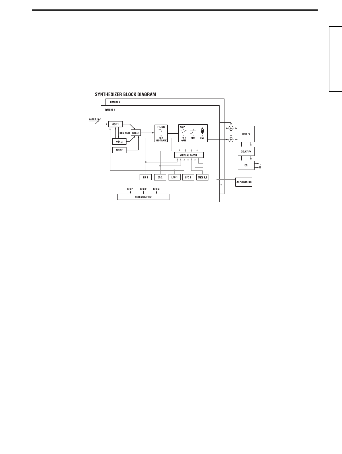
How a program is structured
The programs of the MS2000/MS2000R can be classified in one of two categories depending on the Voice mode setting (LCD
Edit mode Page 01A: COMMON “Mode”): synth programs whose “Mode” is Single/Dual/Split, and vocoder programs
whose “Mode” is Vocoder.
Synth programs
As shown in the diagram below, a synth program consists of timbres, effects, and an arpeggiator.
(in the case of Dual/Split)
Free Assign
KBD Track
Velocity
Free Assign
TIMBRE 1/2
A timbre consists of OSC1/OSC2/NOISE, MIXER, FILTER,
AMP, EG, LFO, VIRTUAL PATCH, and MOD SEQUENCE. If
the voice mode is Single, only TIMBRE 1 will sound. If the
voice mode is Dual or Split, both timbres TIMBRE 1 and
TIMBRE 2 will sound.
OSC1/OSC2/NOISE
OSC1 (Oscillator 1) allows you to select from eight different
oscillator algorithms, including basic analog synthesizer
waveforms such as SAW and PWM, Cross Modulation,
and the DWGS (Digital Waveform Generator System)
used on the Korg DW-8000 synthesizer.
A waveform input from the AUDIO IN 1/2 jacks can also
be processed.
OSC2 (Oscillator 2) allows you to select from three types:
SAW, SQU, and TRI. It can also be used as a modulator
oscillator for the Sync or Ring modulation characteristic of
analog synthesizers.
NOISE (Noise Generator) produces white noise. This can
be used for sound effects, etc.
MIXER
Here you can adjust the levels of OSC1, OSC2 and NOISE,
and send the combined signal to the FILTER.
FILTER
The FILTER cuts or emphasizes frequency components of
the signal from the oscillator, thus adjusting the tone
(brightness, etc.). These filter settings will significantly
affect the sound.
You can select from four types of filter: –12 or –24 dB/oct
LPF (Low Pass Filter), –12 dB/oct BPF (Band Pass Filter), or
–12 dB/oct HPF (High Pass Filter).
Use EG1 to create time-variant changes in cutoff frequency.
AMP
This consists of AMP (Amplifier), DIST (Distortion), and
PAN (Panpot).
AMP sets the volume, and PAN sets the stereo location.
Use EG2 to create time-variant changes in volume.
You can produce hard\harsh tones by turning DIST on. By
adjusting the filter cutoff and resonance, strong effects can
be produced.
EG1/2
An EG (Envelope Generator) applies a time-variant change
to a sound parameter.
On the MS2000/MS2000R, there are two EG’s for each timbre. Each EG consists of four parameters: ATTACK (attack
time), DECAY (decay time), SUSTAIN (sustain level), and
RELEASE (release time).
EG1 is assigned as the envelope source that produces timevariant change in the FILTER cutoff frequency.
EG2 is assigned as the envelope source that produces timevariant change in the AMP volume.
If you wish to assign EG1 and EG2 to other parameters,
you can make VIRTUAL PATCH settings to do so.
LFO 1/2
The LFO (Low Frequency Oscillator) applies cyclic change
to sound parameters.
The MS2000/MS2000R provides two LFO’s for each timbre, each with four waveforms.
LFO1 is assigned as the modulation source for OSC1.
LFO2 is assigned as the modulation source for the pitch
modulation controlled by the modulation wheel.
If you wish to assign LFO1 and LFO2 to other parameters,
you can make VIRTUAL PATCH settings to do so.
IntroductionFront and rear panelConnectionsPlayingEditing
3
Page 10
VIRTUAL PATCH
VIRTUAL PATCH allows you to use not only EG or LFO,
but even velocity (keyboard playing dynamics) or keyboard tracking (the area of the keyboard you play) as modulation sources which can be assigned to sound parameters
for greater freedom in creating sounds. Four routings (combinations) can be specified for each timbre.
EFFECTS
Each program has a modulation effect, delay, and equalizer.
For a modulation-type effect, you can select from three
effects such as chorus.
For a delay effect, you can select from three types of delay,
including a stereo delay.
MOD SEQUENCE
MOD SEQUENCE is a step sequencer that lets you apply
time-variant change to various sound parameters in a way
similar to analog synthesizers of the past.
Use the sixteen knobs on the front panel to set the value of
each step, and playback to make the sound change.
You can also operate the knobs in realtime, and record their
movements (parameter values) in each step (Motion Rec
function).
Since each timbre can have up to three sequences, you can
obtain very complex tonal changes.
ARPEGGIATOR
This is an arpeggiator with six types of arpeggio type.
For a program whose voice mode is Dual/Split, arpeggios
can be played on one or both timbres.
Since arpeggiator settings can be made for each program,
you can create and save an arpeggio type that is suitable for
the sound of that program.
Vocoder programs
Vocoder programs consist of OSC1/NOISE, MIXER, VOCODER SEC., EFFECT, and ARPEGGIATOR. The vocoder takes a
signal from the internal tone generator (OSC1/NOISE) or the AUDIO IN 1 jack, applies to it the characteristics of the signal
that is input from the AUDIO IN 2 jack, and outputs the result. The most popular use for this is to input a voice from a mic
connected to the AUDIO IN 2 jack, in order to create the effect of an instrument speaking.
OSC1/NOISE/AUDIO IN 1 jack (carrier)
The OSC1/NOISE signal will be the carrier to which the
vocoder effect is applied. Waveforms that contain large
numbers of overtones such as SAW and VOX WAVE are
ideal for the carrier waveform.
It is also possible to apply the vocoder effect to a waveform
that is input to the AUDIO IN 1 jack together with OSC1/
NOISE.
The volumes of OSC1/NOISE/AUDIO IN are adjusted by
the MIXER, and the combined signal is output to the
VOCODER SEC.
AUDIO IN 2 jack (modulator)
The signal that is input to the AUDIO IN 2 jack will be the
modulator. In general, it is most common for a voice to be
input to the modulator, but you can create unique effects by
inputting rhythm sounds or other waveforms.
4
VOCODER SEC.
This consists of two sets of 16 band-pass filters (ANALYSIS
FILTER and SYNTHESIS FILTER) and the ENVELOPE
FOLLOWER.
The audio signal from the AUDIO IN 2 jack (modulator) is
input to sixteen bandpass filters (ANALYSIS FILTER), and
the ENVELOPE FOLLOWER detects the volume envelope
(time-variant change) of each frequency band.
Then, the signal from the internal tone generator or the
AUDIO IN 1 jack (carrier) is input to the other set of 16
band-pass filters (SYNTHESIS FILTER), and processed by
the envelopes detected by the ENVELOPE FOLLOWER to
modulate the carrier with the features of the voice, producing the impression that the instrument or sound is talking
(vocoder effect).
It is also possible to use the FORMANT SHIFT or CUTOFF
parameters to change each frequency of the carrier bandpass filter. This will cause the frequency response curve to
be raised or lowered while preserving the character of the
modulator, and will dramatically affect the tone.
Page 11
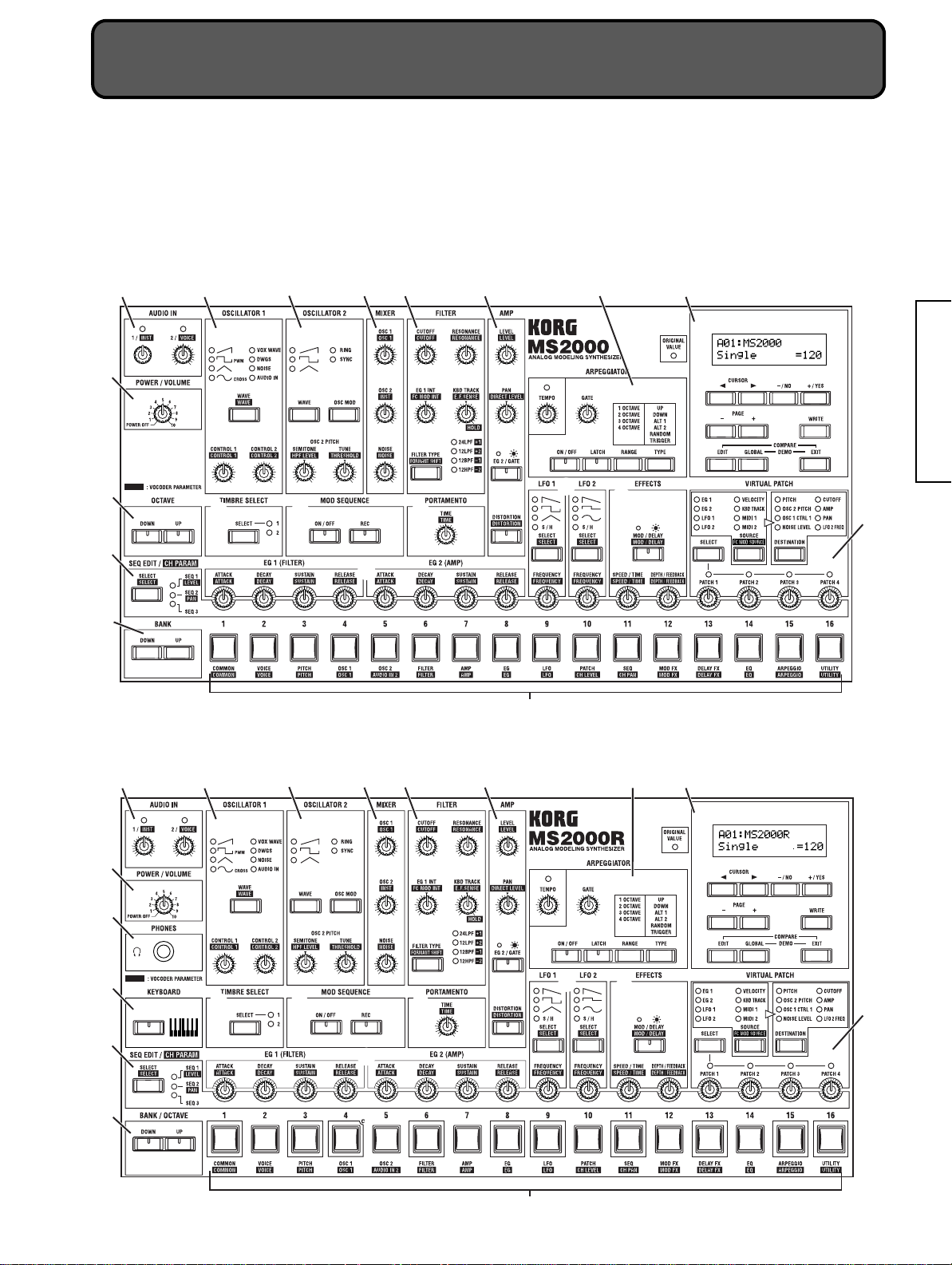
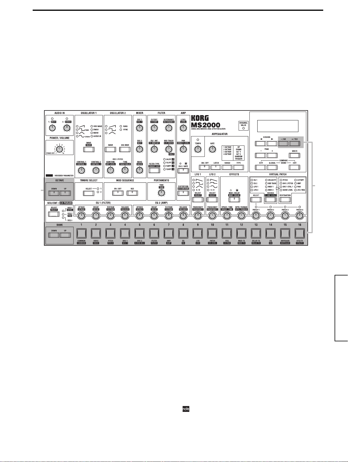
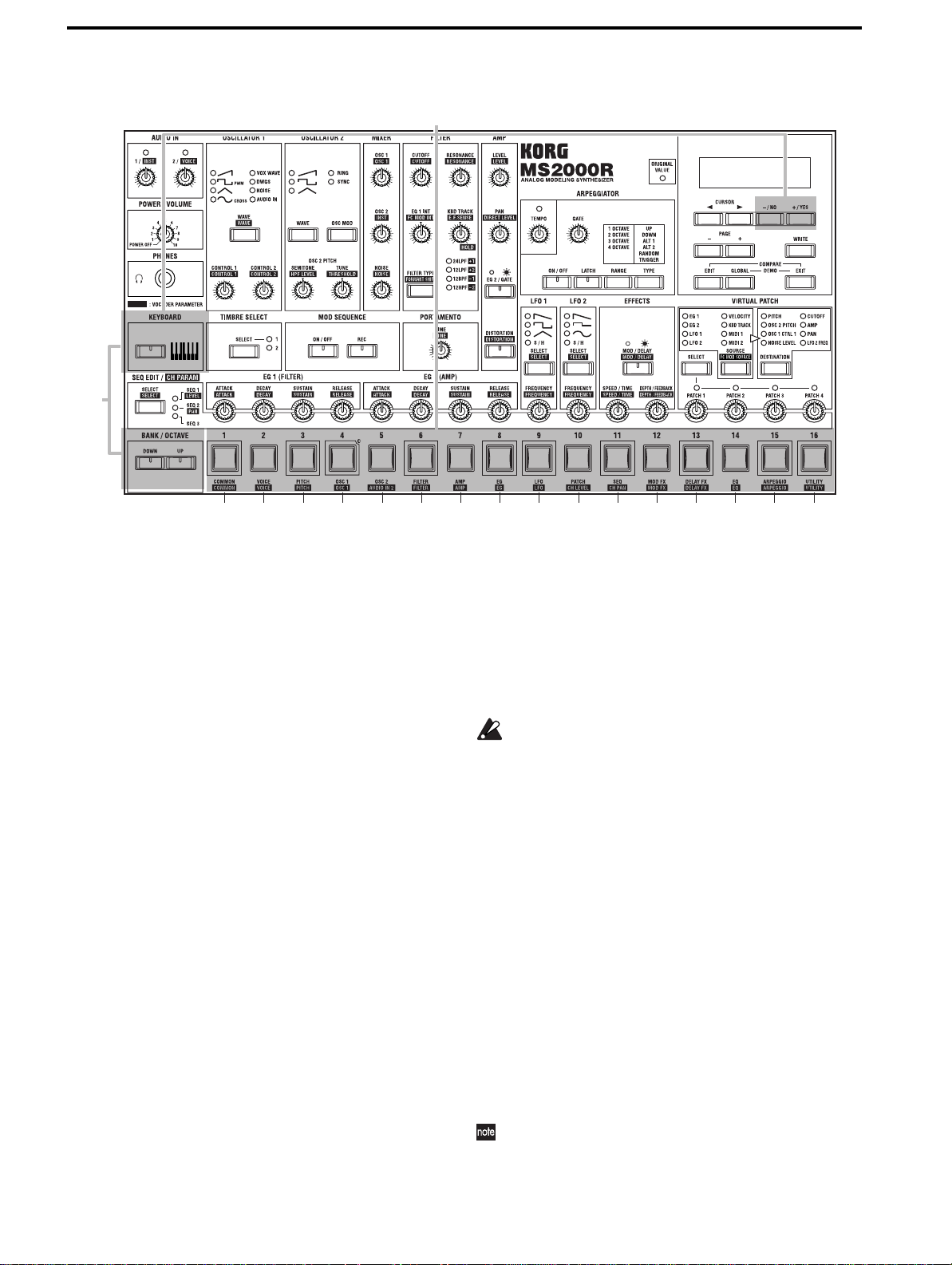
Front and rear panel
Front panel
The characters printed inverse white on the front panel are vocoder program parameters (LCD Edit mode Page 01A: COMMON “Mode” = Vocoder).
MS2000
IntroductionFront and rear panelConnectionsPlayingEditing
2
1
G
H
I
MS2000R
3
4
6 7
5
C
8
B
DEF
J
A
9
0
1
K
G
H
I
2
3
F
4
E
6 7
5
C
D
J
B
A
8
9
0
5
Page 12
1 POWER/VOLUME
[POWER/VOLUME] knob
This turns the power on/off and adjusts the volume.
2 AUDIO IN
[1/ ] knob
This adjusts the input level of the AUDIO IN 1 jack.
[2/ ] knob
This adjusts the input level of the AUDIO IN 2 jack.
3 OSCILLATOR 1
[WAVE• ] key
This selects the waveform for oscillator 1.
The LED for the selected waveform will light.
[CONTROL 1• ] knob
This adjusts a waveform parameter.
The parameter will depend on the selected waveform.
[CONTROL 2• ] knob
This adjusts a waveform parameter.
The parameter will depend on the selected waveform.
4 OSCILLATOR 2
[WAVE] key
This selects the waveform for oscillator 2.
The LED for the selected waveform will light.
6 FILTER
[FILTER TYPE• ] key
For synth programs, this selects the filter type.
The LED for the selected filter type will light.
For vocoder programs, this selects the formant shift.
The LED for the selected formant shift will light.
[CUTOFF• ] knob
For synth programs, this sets the filter cutoff frequency.
For vocoder programs, this sets the cutoff frequency of
the synthesis filter.
[RESONANCE• ] knob
For synth programs, this sets the amount of filter resonance.
For vocoder programs, this sets the amount of resonance
for the synthesis filter.
[EG1 INT• ] knob
For synth programs, this adjusts how much the filter
cutoff frequency will be affected by the time-variant
change produced by EG1.
For vocoder programs, this adjusts the depth of the
modulation that is applied to the cutoff frequency of the
synthesis filter. The modulation source can be selected
by .
[KBD TRACK• ] knob
For synth programs, this adjusts the filter keyboard
tracking (change in cutoff frequency that will occur
according to the keyboard location you play).
For vocoder programs, this adjusts the sensitivity of the
ENVELOPE FOLLOWER for the vocoder sec.
[OSC MOD] key
This selects how the oscillator 2 will modulate by oscillator 1. The modulated waveform will be output from
oscillator 2.
[SEMITONE• ] knob
For synth programs, this sets the pitch of oscillator 2 in
semitone steps.
For vocoder programs, this sets the output level of the
HPF (high pass filter) that is applied to the signal
received at the AUDIO IN 2 jack.
[TUNE• ]knob
For synth programs, this is a fine adjustment for the
pitch of oscillator 2.
For vocoder programs, this sets the threshold level at
which the signal input from the AUDIO IN 2 jack will be
cut.
5 MIXER
[OSC1• ] knob
This adjusts the volume of oscillator 1.
[OSC2• ] knob
For synth programs, this adjusts the volume of oscillator
2.
For vocoder programs, this adjusts the volume of the
signal that is input from the AUDIO IN 1 jack.
[NOISE• ] knob
This adjusts the volume of the noise generator.
7 AMP
[LEVEL• ] knob
For synth programs, this adjusts the volume of each tim-
bre.
For vocoder programs, this adjusts the volume of the
internal tone generator carrier (OSC1/NOISE).
[PAN• ] knob
For synth programs, this sets the output panning for
each timbre.
For vocoder programs, this sets the level at which the
signal from the AUDIO IN 2 jack will be output directly.
[EG 2/GATE] key
This selects the envelope source for the volume.
[DISTORTION• ] key
This switches distortion on/off.
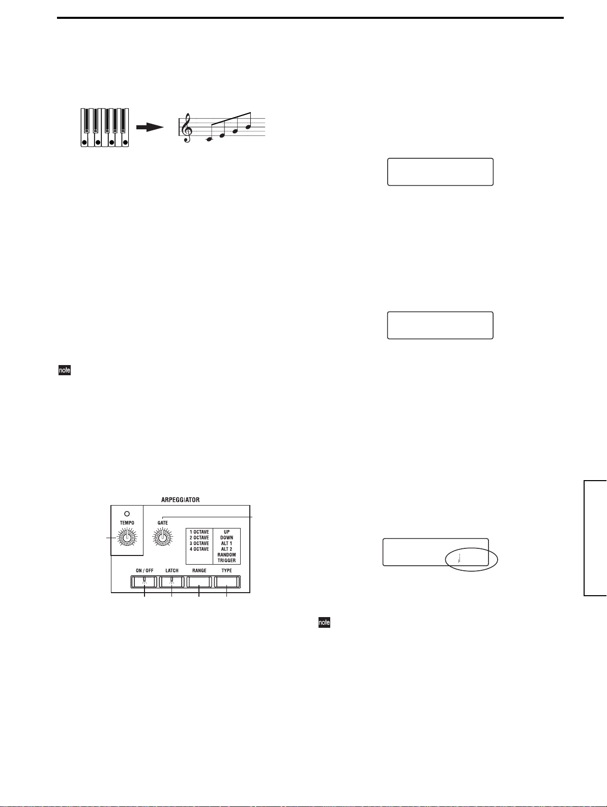
8 ARPEGGIATOR
[TEMPO] knob
This sets the tempo of the arpeggio performance.
This setting will also determine the MOD SEQUENCE
playback speed, and is used when synchronizing the
LFO frequency to the tempo.
[GATE] knob
This adjusts the length of the notes sounded by the
arpeggiator.
[ON/OFF] key
This turns the arpeggiator on/off.
6
Page 13
Basic Guide
[LATCH] key
If this is on, the arpeggiator will continue playing even if
you release your hand from the keyboard.
[RANGE] key
This sets the range in which the arpeggio will be played.
[TYPE] key
This selects the arpeggio type.
9 KEY & DISPLAY
ORIGINAL VALUE LED
When editing, this will light when the value currently
selected by the knob or key matches the written value.
LCD
In Program Play mode, this will display information
such as the program number and program name.
In LCD Edit and Global modes, this will display
parameters.
CURSOR [√][®] keys
In LCD Edit and Global modes, these are used to select
the parameter that you wish to edit.
[+/YES] [–/NO] keys
In Program Play mode, these are used to select programs.
In LCD Edit and Global modes, these are used to set
values, and to write or copy data.
PAGE [+][–] keys
These are used to switch pages.
[EDIT] key
This key enters LCD Edit mode.
While you are editing a program, you can hold down
this key and press the [EXIT] key to return to the original written settings (the Compare function).
[GLOBAL] key
This key enters Global mode
By holding down the [EXIT] key and then holding down
this key, you can enter Demo mode.
A EFFECTS
[MOD/DELAY• ] key
This selects the effect that will be edited.
[SPEED/TIME• ] knob
This adjusts the modulation speed of the modulation
effect or the delay time of the delay effect.
[DEPTH/FEEDBACK• ] knob
This adjusts the effect depth and the amount of feedback.
B LFO1/LFO2
[SELECT• ] key
This selects the LFO waveform.
[FREQUENCY• ] knob
This sets the LFO frequency.
C EG1/EG2
[ATTACK• ] knob
This sets the attack time (rise time).
[DECAY• ] knob
This sets the decay time (the time from when the attack
time is completed until the sustain level is reached).
[SUSTAIN• ] knob
This adjusts the sustain level (the level that will be held
while the note is sustained).
[RELEASE• ] knob
This sets the release time (the time from when you
release the note until it decays).
D PORTAMENTO
[TIME• ] knob
This determines how portamento will be applied.
IntroductionFront and rear panelConnectionsPlayingEditing
[WRITE] key
Use this key to save the settings you edit.
[EXIT] key
From any mode, this key lets you return to Program
Play mode.
It is also used to cancel a write or copy operation.
0 VIRTUAL PATCH
[SELECT] key
This selects the patch.
[SOURCE• ] key
For synth programs, this selects the modulation source.
For vocoder programs, this selects the modulation
source that is applied to the synthesis filter cutoff frequency.
[DESTINATION] key
This selects the parameter to which modulation will be
applied.
[PATCH1], [PATCH2], [PATCH3], [PATCH4] knobs
These adjust the depth of modulation.
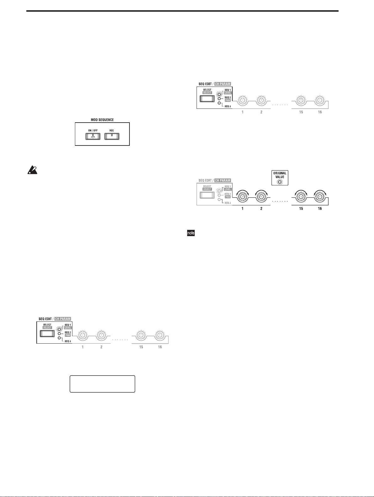
E MOD SEQUENCE
[ON/OFF] key
This switches the sequence on/off.
[REC] key
Use this when you wish to record realtime knob movements as a sequence.
F TIMBRE SELECT
[SELECT] key
When editing a Dual/Split program, this switches
between the two timbres for editing.
7
Page 14
G OCTAVE (MS2000), KEYBOARD (MS2000R)
MS2000
OCTAVE [UP], [DOWN] keys
These shift the pitch range of the keyboard in one-octave
steps.
MS2000R
[KEYBOARD] key
If this key is pressed to make the LED light, you can use
the SELECT [1]–[16] keys to play the program.
H SEQ EDIT/
[SELECT• ] key
For synth programs, this selects a sequence when creating or editing sequence data. When a sequence is
selected, use the sixteen knobs at the right to create the
sequence data.
For a vocoder program, this is used to set the synthesis
filter levels and panpot. In this case, the sixteen knobs at
the right are used to set the various parameter values.
I BANK (MS2000), BANK/OCTAVE (MS2000R)
MS2000
[UP], [DOWN] keys
Select the program bank.
MS2000R
[UP], [DOWN] keys
If the [KEYBOARD] key is off (LED dark), these select
the program bank.
If the [KEYBOARD] key is on (LED lit), these change the
pitches assigned to the SELECT [1]–[16] keys in oneoctave steps.
J SELECT [1]–[16] keys
In Program Play mode, use these to select programs.
In LCD Edit mode, use these to select pages.
On the MS2000R, turning the [KEYBOARD] key on
(LED lit) will cause these keys to function as a convenience MIDI keyboard, which you can use to play the
program.
K PHONES jack (MS2000R)
Connect a set of headphones to this jack.
Rear panel
456
1 OUTPUT
L/MONO, R jacks
Connect these to your powered monitor speakers, stereo
amp, mixer, or multitrack recorder. If you are playing in
mono, make connections to the L/MONO jack.
2 AUDIO IN
AUDIO IN 1 jack
For synth programs, connect a synthesizer or audio
device here. The input signal can be used as the oscillator 1 waveform.
For vocoder programs, this will be the input jack for the
external carrier of the vocoder.
AUDIO IN 2 jack
For synth programs, connect a synthesizer or audio
device here. This can be used together with the AUDIO
IN 1 jack as the oscillator 1 waveform.
For vocoder programs, connect a mic to this jack, and
input the modulator audio signal.
3
2
1
3 ASSIGNABLE
SWITCH jack
Connect a switch pedal here.
PEDAL jack
Connect a volume pedal (expression pedal) here.
4 MIDI
MIDI IN connector
MIDI data is received at this connector. Connect it to an
external MIDI device.
MIDI OUT connector
MIDI data is transmitted from this connector. Connect it
to an external MIDI device.
MIDI THRU connector
MIDI data received at MIDI IN is re-transmitted without
change from this connector. Use it when you wish to
connect three or more MIDI devices.
[AUDIO IN 2 Level] switch
Set this according to the input source that is connected
to the AUDIO IN 2 jack. If a mic is connected, set this to
MIC. If a synthesizer or audio device is connected, set
this to LINE.
5 DC 9V
Connect the included AC adapter here.
8
Page 15
6 Cable hook
Wrap the AC adapter power cable around this to prevent accidental disconnection.
When unwrapping the cable from the hook, do not
apply excessive force to the cable.
Basic Guide
Control panel (MS2000)
1
2
3
1 PITCH BEND wheel
This controls the pitch.
2 MODULATION wheel
This controls the modulation depth.
With the factory settings, it will control the depth of the
modulation applied by the LFO2 to the oscillator pitch.
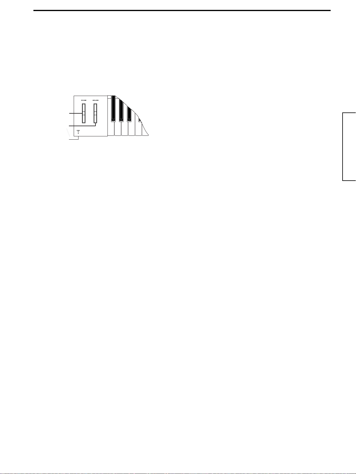
3 PHONES jack
A set of headphones can be connected here.
IntroductionFront and rear panelConnectionsPlayingEditing
9
Page 16
AC adapter (included)
Connect to
an AC outlet
Connections
MIDI IN
MIDI keyboard, tone generator module, sampler etc.
Be sure to turn off the power of all devices before making connections. Failing to take this precaution may
cause your speaker system to be damaged, or may
cause malfunctions.
MIDI OUT
Connecting the AC adapter
Connect the included AC adapter.
After you have connected the AC adapter to the MS2000/
MS2000R, plug it into an AC outlet.
Connecting external devices
Connect the OUTPUT jacks (L/MONO, R) of the MS2000/
MS2000R to your audio system (mixer, powered monitor
system etc.).
In order to take full advantage of the potential of the
MS2000/MS2000R, we recommend that you use stereo output.
If you are making monaural connections, use the L/MONO
jack.
Monitor speakers
(amplified)
b. ASSIGNABLE SWITCH jack
If you wish to use a pedal switch to change programs, to
change the octave up/down, or to turn portamento or the
arpeggiator on/off, connect a PS-1 switch pedal (sold separately) or DS-1H damper pedal (sold separately). The function that will be controlled is determined by the
“A.SwFunc” setting in Global mode Page 6B: PEDAL&SW
(☞Parameter guide p.56). With the factory settings, this is
set to Damper.
Connecting MIDI devices
If you wish to connect the MS2000/MS2000R to an external
MIDI device, use a MIDI cable to make connections.
1. Using the MS2000/MS2000R as a tone generator module
To use the MS2000/MS2000R as a tone generator module,
use a MIDI cable to connect the MS2000/MS2000R’s MIDI
IN connector to the MIDI OUT of the external MIDI device.
MIDI OUT
MIDI IN
Connecting pedals and switches
By connecting a volume pedal and a switch pedal you can
expand your performance possibilities.
Connect a pedal and/or switch pedal as necessary. You can
set the polarity of the pedal in Global mode Page 6:
PEDAL&SW. (☞Parameter guide p.56)
a. ASSIGNABLE PEDAL jack
If you wish to use a pedal to control breath control, volume,
pan, or expression, connect an EXP-2 expression pedal
(sold separately) or an XVP-10 EXP/VOL pedal (sold separately) etc.
The function that will be controlled is determined by the
“A.Pedal” setting in Global mode Page 6A: PEDAL&SW
(☞Parameter guide p.56). With the factory settings, this is
set to Exp Pdl.
10
External MIDI device
MS2000/MS2000R
2. Playing an external MIDI device
If you wish to play an external MIDI device from the keyboard of the MS2000 or from the SELECT [1]–[16] keys of
the MS2000R, use a MIDI cable to connect the MIDI OUT
connector of the MS2000/MS2000R to the MIDI IN connector of the external MIDI device.
MIDI OUT
MS2000/MS2000R
MIDI IN
External MIDI device
Page 17
Basic Guide
3. Setting the MIDI channel (preparations for playing)
If you are using the MS2000/MS2000R as a tone generator
module, or if you are using the MS2000 as a master keyboard to play an external MIDI device, you must set the
MIDI channel of the MS2000/MS2000R to match the MIDI
channel of the external MIDI device before you can begin
playing.
Use the following procedure to set the MIDI channel.
a. Check the connections
● Make sure that the MS2000/MS2000R is correctly con-
nected to the external MIDI device (☞p.10).
b. Set the MIDI channel of the MS2000/MS2000R
The Global MIDI channel of the MS2000/MS2000R is set in
Global mode Page 3A: MIDI “MIDI Ch.”
1 Press the [GLOBAL] key.
You will enter Global mode.
2 Press the SELECT [5] key.
Page 3A: MIDI “MIDI Ch” will appear in the LCD
screen.
3A MIDI
MIDI Ch:01
With the factory settings, the global MIDI channel is set
to 1.
3 Use the [+/YES] [–/NO] keys to set the MIDI channel.
4 Press the [EXIT] key to return to Program Play mode.
c. Set the MIDI channel of the connected device
Set the MIDI channel of the connected external MIDI
device to match the MIDI channel you set for the MS2000/
MS2000R.
For the procedure, refer to the owner’s manual of the connected device.
Global parameters that you edit will return to their
unedited setting if you turn off the power without saving. To save your edits, you must perform the Write
operation. (☞p.30)
Connections to a computer/ sequencer
1. Connecting the MS2000 to a computer/ sequencer
If you wish to perform on the MS2000 keyboard, record
your performance on a computer or sequencer, and then
play back the performance on the MS2000 (i.e., using the
MS2000 as both a MIDI keyboard for input and as a MIDI
tone generator), connect the MS2000 to your computer/
sequencer using a MIDI interface as shown below.
MIDI interface
Computer
MIDI IN
If the echo back setting of the sequencer is turned on,
duplicate notes will be sounded when you play the
MS2000 keyboard. To prevent this, turn the Global
mode Page 3B: MIDI “Local” setting OFF to break the
connection inside the MS2000.
However, be aware that if “Local” is OFF, it will not be
possible to play the MS2000 by itself.
MIDI OUT
MIDI OUT
MS2000
2. Connecting the MS2000R to a computer/sequencer
If you wish to connect the MS2000R to a computer/
sequencer, use a MIDI interface to connect the MS2000R,
master keyboard, and computer as shown below.
MIDI IN
MIDI interface
IntroductionFront and rear panelConnectionsPlayingEditing
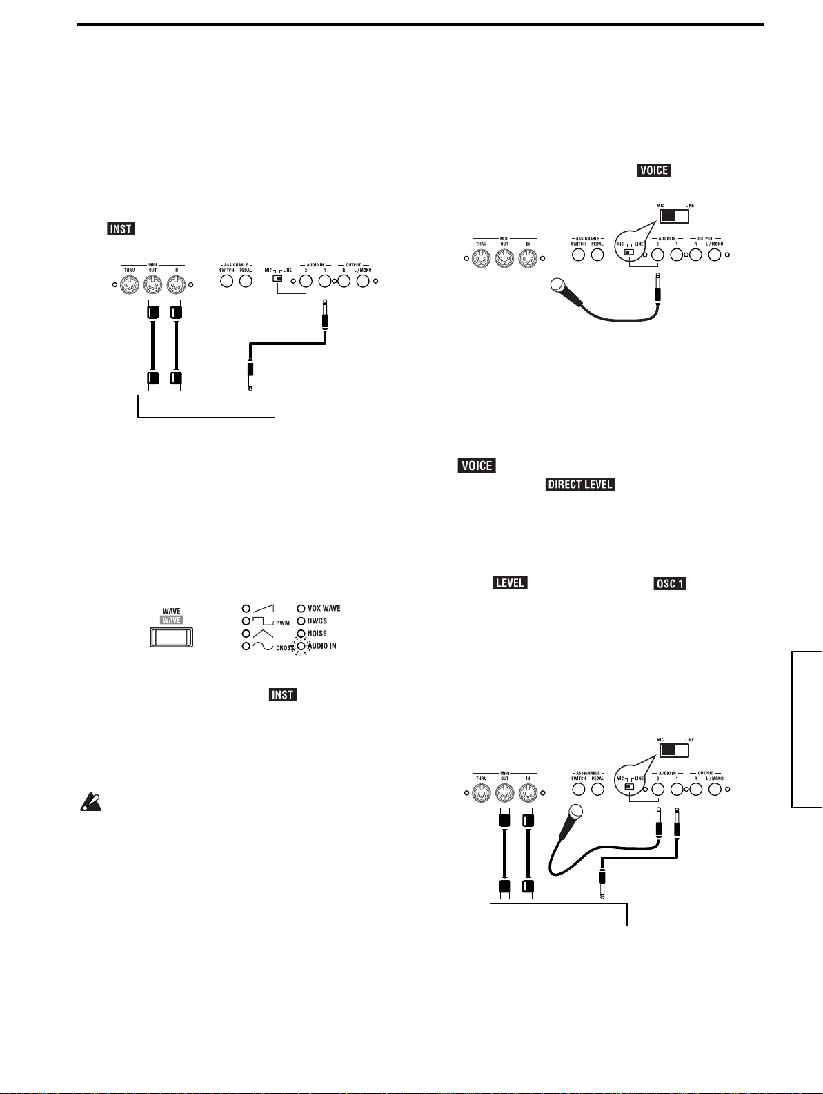
Connections to the AUDIO IN jacks
If you wish to modify the sound of an external synthesizer,
sampler or other audio source or want use the MS2000/
MS2000R as a vocoder, connect your equipment to the
AUDIO IN jack(s).
For details on connections and settings, refer to the Basic
Guide section entitled “Using external input” (☞p.17).
Computer
MIDI IN
MS2000R
In order to connect to your computer, you will need a
MIDI interface. Please purchase an interface suitable
for your computer. For details on connections between
your computer and MIDI interface, and on MIDI port
settings, refer to the owner’s manual for your MIDI
interface.
MIDI OUT
MIDI IN
MIDI OUT
MIDI keyboard
11
Page 18
Playing
= DEMO SONG #1 =
Demo Song No.1
Turning the power on/off and adjusting the volume
a. Turn on the power
Before turning on the power of the MS2000/MS2000R, turn
off the power of the connected devices.
1 Rotate the [POWER/VOLUME] knob to turn on the
power.
The Program Play mode screen will appear.
When the power is first turned on, you will always be in
Program Play mode.
The upper line of the LCD will show the bank, number,
and name of the program. The lower line will show the
voice mode of the program, and the tempo.
Program bank and number
A01:MS2000/R
Single
Voice mode
2 Turn on the power of the connected devices.
b. Adjust the volume
● Rotate the [POWER/VOLUME] knob to an appropriate
level.
The headphone volume is also adjusted by this knob.
=120
Tempo
Program
name
Listen to the demo performance
The MS2000/MS2000R contains several demo songs. Listen
to the demo songs to hear the rich sounds and their expressive potential.
a. Play back the demo songs
● Hold down the [EXIT] key and the [GLOBAL] key for
approximately one second.
Hold down the [EXIT] key, and then press and hold the
[GLOBAL] key.
The demo songs will begin playing consecutively, starting with the first song.
The LCD screen will show the song name.
b. Select a demo song
● During playback, use the [+/YES] [–/NO] keys.
The demo song will change.
The LCD screen will indicate the name of the selected
demo song.
c. Exit the demo performance
● Press the [EXIT] key.
You will return to Program Play mode.
All demo songs: © 2000 korg Inc. — all rights reserved.
c. Turn off the power
1 Turn off the power of the connected devices.
2 Rotate the [POWER/VOLUME] knob all the way to the
left.
Rotate it until it clicks off.
The power of the MS2000/MS2000R will be off.
12
Page 19
Basic Guide
Playing a program
Here’s how to select and play a program.
The MS2000/MS2000R contain a total of 128 programs, with 16 programs in each of eight banks (A–H).
You can select programs in Program Play mode. If the LCD screen shows that you are in LCD Edit mode or Global mode,
press the [EXIT] key.
The method of changing the program or pitch differs between the MS2000 and the MS2000R. Also, the SELECT [1]–[16] keys
can be used to play a program only on the MS2000R.
MS2000
IntroductionFront and rear panelConnectionsPlayingEditing
2
1. Select a program
There are two ways to select a program.
a. Using the BANK [UP] [DOWN] keys and the SELECT
[1]–[16] keys
This method lets you directly select the desired program.
1 Use the BANK [UP] [DOWN] keys to select the desired
program bank.
Pressing these keys will switch between banks A–H. The
selected bank will be shown in the LCD screen.
2 Use the SELECT [1]–[16] keys to select the desired pro-
gram number.
The numbers above each key correspond to the program
number.
b. Using the [+/YES] [–/NO] keys
● Press the [+/YES] key.
Each time you press the key, the program number will
increase by one.
● Press the [–/NO] key.
Each time you press the key, the program number will
decrease by one.
A01:MS2000
Single
=120
1
2. Changing the pitch sounded by the keyboard in one-octave steps
The pitch assigned to the keyboard can be changed over a
range of ±2 octaves.
a. Raising the pitch
● Press the OCTAVE [UP] key.
Pressing the key once will make the key LED light green,
and the pitch will be one octave higher.
Pressing the key twice will make the key LED light red,
and the pitch will be two octaves higher.
To return to the original pitch, press the [DOWN] key.
b. Lowering the pitch
● Press the OCTAVE [DOWN] key.
Pressing the key once will make the key LED light green,
and the pitch will be one octave lower.
Pressing the key twice will make the key LED light red,
and the pitch will be two octaves lower.
To return to the original pitch, press the [UP] key.
The setting of the BANK/OCTAVE [UP][DOWN] keys
cannot be saved for individual programs. If you wish to
change the pitch for a specific program, use the LCD
Edit mode Page 04A: PITCH “Transpose” parameter.
(☞Parameter guide p.36, Page 04A: PITCH “Transpose”)
13
Page 20
MS2000R
1, 2
3
A A#B C
C#D D#E F F#G G
1. Selecting a program
There are two ways to select a program.
a. Using the BANK/OCTAVE [UP] [DOWN] keys and
the SELECT [1]–[16] keys
This method lets you directly select the desired program.
1 Press the [KEYBOARD] key to make the key LED go
dark.
2 Use the BANK/OCTAVE [UP] [DOWN] keys to select
the desired program bank.
Pressing these keys will switch between banks A–H. The
selected bank will be shown in the LCD screen.
3 Use the SELECT [1]–[16] keys to select the desired pro-
gram number.
The numbers above each key correspond to the program
number.
b. Using the [+/YES] [–/NO] keys
● Press the [+/YES] key.
Each time you press the key, the program number will
increase by one.
● Press the [–/NO] key.
Each time you press the key, the program number will
decrease by one.
2. Use the SELECT [1]–[16] keys to play the program
On the MS2000R, you can use the SELECT [1]–[16] keys to
play the program.
1 Press the [KEYBOARD] key to make the key LED
light.
2 Press the SELECT [1]–[16] keys.
14
The program will sound. The correspondence between
A01:MS2000R
Single
#
A A#B C
the SELECT [1]–[16] keys and their pitches is shown in
the illustration above.
=120
3. Changing the pitch sounded by the keys in one-octave steps
The pitch assigned to the SELECT [1]–[16] keys can be
changed over a range of ±2 octaves.
This setting has no effect on the pitches that will be
generated by a MIDI keyboard or other external MIDI
devices that are connected to the MS2000R.
● Before you begin, press the [KEYBOARD] key to make
the key LED light.
a. Raising the pitch
● Press the BANK/OCTAVE [UP] key.
Pressing the key once will make the key LED light green,
and the pitch will be one octave higher.
Pressing the key twice will make the key LED light red,
and the pitch will be two octaves higher.
To return to the original pitch, press the [DOWN] key.
b. Lowering the pitch
● Press the BANK/OCTAVE [DOWN] key.
Pressing the key once will make the key LED light green,
and the pitch will be one octave lower.
Pressing the key twice will make the key LED light red,
and the pitch will be two octaves lower.
To return to the original pitch, press the [UP] key.
The setting of the BANK/OCTAVE [UP][DOWN] keys
cannot be saved for individual programs. If you wish to
change the pitch for a specific program, use the LCD
Edit mode Page 04A: PITCH “Transpose” parameter.
(☞Parameter guide p.36, Page 04A: PITCH “Transpose”)
Page 21
Basic Guide
Range: 1 Octave
A01:MS2000/R
Type: Up
A01:MS2000/R
Playing arpeggios
The MS2000/MS2000R contain a built-in arpeggiator that
sounds an arpeggiated (broken) chord when you hold down
a chord on the keyboard.
When you hold down a chord on the keyboard, it will be sounded
as shown at right (Arpeggio Type: Up)
1. Play a program in which the arpeggiator is turned on
Some of the factory preset programs have the arpeggiator
turned on. Here’s how to select and play one of these programs.
1 Select a program for which the ARPEGGIATOR [ON/
OFF] key is lit.
Programs for which the [ON/OFF] key is lit have the
arpeggiator turned on. The arpeggio type and other settings will be appropriate for the sound of the program.
2 Hold down a chord on the keyboard.
An arpeggio will begin playing.
On the MS2000R if you press the [KEYBOARD] key to
make the key LED light, you will be able to use the
SELECT [1]–[16] keys to play arpeggios (☞p.14 “2. Use
the SELECT [1]–[16] keys to play the program”).
2. Using the knobs and keys to modify the settings
You can use the front panel knobs and keys to modify the
arpeggiator settings.
e
f
Each time you press the key, the setting will alternate
between on and off.
c. Setting the pitch range of the arpeggio
1 Press the [RANGE] key.
The pitch range will be displayed in the lower line of the
LCD screen.
Each time you press the key, the pitch range will change
between 1–4 octaves.
2 Press the [EXIT] key.
The previous LCD screen will reappear.
d. Selecting the arpeggio type
1 Press the [TYPE] key.
The lower line of the LCD screen will show the arpeggio
type.
Each time you press the key, the arpeggio type will
change.
2 Press the [EXIT] key.
The previous LCD screen will reappear.
e. Adjusting the note length (gate time)
● Rotate the [GATE] knob.
Rotating the knob toward the right will lengthen the
notes, and rotating it toward the left will shorten them.
f. Adjusting the arpeggiator playback speed
● Rotate the [TEMPO] knob.
Rotating the knob toward the right will speed up the
playback speed, and rotating it toward the left will slow
down the playback speed.
The selected speed will be shown in the lower left of the
LCD screen.
A01:MS2000/R
Single =120
IntroductionFront and rear panelConnectionsPlayingEditing
a. Turning the arpeggiator on (off)
● Press the ARPEGGIATOR [ON/OFF] key.
When the [ON/OFF] key is lit, the arpeggiator is on.
When it is dark, the arpeggiator is off.
Each time you press the key, the setting will alternate
between on and off.
b. Maintaining the arpeggiator after you release your
hand from the keyboard
● Press the [LATCH] key to make the key LED light
(LATCH is on).
When LATCH is on, the arpeggiator will continue playing even after you release your hand from the keyboard.
a
b c d
The LED located above the [TEMPO] knob will blink at
quarter note intervals of the MS2000/MS2000R’s internal clock.
The playback speed of the arpeggiator can be synchronized to an external MIDI device. (☞Parameter Guide
p.54, Global parameter Page 3C: MIDI “Clock”)
g. Other arpeggiator-related settings
The arpeggiator also allows you to set the “Key Sync,”
“Resolution,” and “Swing.” For details on these parameters, refer to p.27 of the Basic Guide, Editing section “Editing arpeggio parameters,” and Parameter Guide p.45,
Program parameters “■ ARPEGGIATOR.”
15
Page 22
Using MOD SEQUENCE to modify the sound
1. Playing a program in which MOD SEQUENCE is on
Some of the factory preset programs contain sequence data.
Here’s how to select and play these programs.
1 Select a program whose MOD SEQUENCE [ON/OFF]
key is lit.
Programs whose MOD SEQUENCE [ON/OFF] key is lit
contain sequence data.
For some programs, both the sequence and the arpeggiator will be on, but for this example we recommend
that you select a program in which only the sequence is
on.
2 Play the keyboard.
The program will sound, and the sequence will begin
playing to modify the sound.
The SELECT [1]–[16] keys will light consecutively to
indicate the step that is currently playing.
3 Rotate the [TEMPO] knob.
The speed at which the sound is modified will change.
3. Checking the value recorded for each step
Here’s you to use the sixteen knobs to check the value that
is recorded for each step.
1 Press the SEQ EDIT [SELECT] key to select a sequence
(SEQ 1–3).
2 Rotate the sixteen knobs located beside the SEQ EDIT
LED so that the ORIGINAL VALUE LED is lit.
The number shown below each knob corresponds to the
sequence step.
As you rotate each knob, the position where the ORIGINAL VALUE LED lights will be the value that was
recorded at that step of the sequence.
The value of each step represents the change from the
written or currently-set value of the parameter.
If the SEQ EDIT [SELECT] key has selected a sequence
(SEQ 1–3), you can use the sixteen knobs located beside
the SEQ EDIT LED to edit the data of each step.
2. Checking the parameter that is assigned to each sequence
Here’s how to check the parameter that is assigned to each
sequence.
● Press the SEQ EDIT [SELECT] key to select a sequence
(SEQ 1–3).
The LED of the selected sequence will light, and the
assigned parameter will be displayed in the LCD screen.
If “Cutoff” is assigned to SEQ1
A01:MS2000/R
SEQ1:Cutoff
If all LED’s are dark, no sequence is selected (sequence
select is off). In this case, the voice mode and tempo of
the program will be displayed.
In Program Play mode, you can only check the assigned
parameters. To assign a parameter, use LCD Edit mode
(☞Basic Guide p.25, Edit section “b. Specify sequence
data for each step”).
16
Page 23
Basic Guide
Using external input
1. Modifying an external waveform
A waveform from an external device connected to the
AUDIO IN jack can be modified in the same way as an
internal waveform.
Before you connect an external device, turn off the power
of both devices, and set the MS2000/MS2000R’s AUDIO IN
[1/ ] knob to 0.
1 Connect the external device.
OUT
IN
MIDI
Synthesizer, sampler etc.
2 Turn on the power of both devices.
3 Set the MIDI channel of the MS2000/MS2000R and the
MIDI channel of the connected MIDI device to the
same channel.
For details on setting the MS2000/MS2000R’s MIDI
channel, refer to Basic Guide p.11, Connections “3. Setting the MIDI channel (preparations for playing).”
4 Press the OSCILLATOR 1 [WAVE] key to make the
AUDIO IN LED light.
OUTPUT
2. Using the vocoder function
Here’s how to select a vocoder program (a program whose
voice mode is Vocoder), and try out the vocoder function.
a. Using an internal waveform as the carrier
Before you connect a mic, turn off the power, and set the
MS2000/MS2000R’s AUDIO IN [2/ ] knob to 0.
1 Connect a mic to the AUDIO IN 2 jack.
Mic
2 Set the rear panel [AUDIO IN 2 Level] switch to the
MIC position.
3 Turn on the power of the MS2000/MS2000R.
4 Select a vocoder program.
Programs for which the lower left of the LCD screen
indicates Vocoder are vocoder programs.
5 Input a voice from the mic, and adjust AUDIO IN [2/
] so that the LED does not light red.
By rotating the [ ] knob you can directly
output the voice that was input. Make adjustments
while listening to the voice that is input.
6 While inputting a voice, play the keyboard.
The sound with the vocoder effect will be output.
If you are unable to hear the effect, try adjusting the
AMP [ ] knob or the MIXER [ ] knob.
For details on vocoder editing, refer to Basic Guide p.28,
Editing section “Editing vocoder program.”
IntroductionFront and rear panelConnectionsPlayingEditing
5 Input a waveform from the connected external device,
and adjust the AUDIO IN [1/ ] knob so that the
LED does not light red.
6 Operate the knobs and keys of the FILTER, AMP, EG,
and LFO to modify the input waveform.
For details on parameter settings, refer to Basic Guide
p.20 “Editing a synth program.”
Pitch-related parameters will not apply to the waveform from the AUDIO IN jack.
b. Using an external waveform as the carrier
If you wish to use a waveform that is input from an external device as the carrier, make settings as described in both
of the previous sections “1. Modifying an external waveform” and “2. Using the vocoder function.”
Make connections as shown below.
Mic
OUT
IN
MIDI
Synthesizer, sampler etc.
OUTPUT
17
Page 24
Editing
Editing program parameters
Programs consist of a large number of parameters. In order
to create a program from scratch, you will need to understand all of these parameters. Instead of this, we suggest that
you select a factory preset program, and try editing it in
order to understand each parameter.
Basic editing procedures
The basic procedures for editing are explained below.
You can edit a program in Program Play mode or in LCD
Edit mode.
1. Editing in Program Play mode
In Program Play mode, you can not only select and play a
program, but also use the front panel knobs and keys to
edit the sound of the program as you play, for example by
adjusting the filter cutoff or slightly slowing the attack.
The parameters that correspond to each key will change
value or be switched on/off each time you press the key,
and their status will be shown by the LED or in the LCD
screen.
The parameters that correspond to each knob can be
adjusted in “analog” fashion as indicated by the markings
around the knob.
For both knobs and keys, the ORIGINAL VALUE LED will
light when their setting matches the original written value.
2. Editing in LCD Edit mode
Use LCD Edit mode to edit parameters for which there is
no knob or key, or to edit while checking the parameter
value in the LCD screen.
a. Enter LCD Edit mode
● Press the [EDIT] key.
You will enter LCD Edit mode. The upper line of the
LCD screen will show the page number and the page
name. The lower line will show the parameter name and
value.
Page number
01A COMMON
Mode: Split
Parameter name
Page name
Parameter value
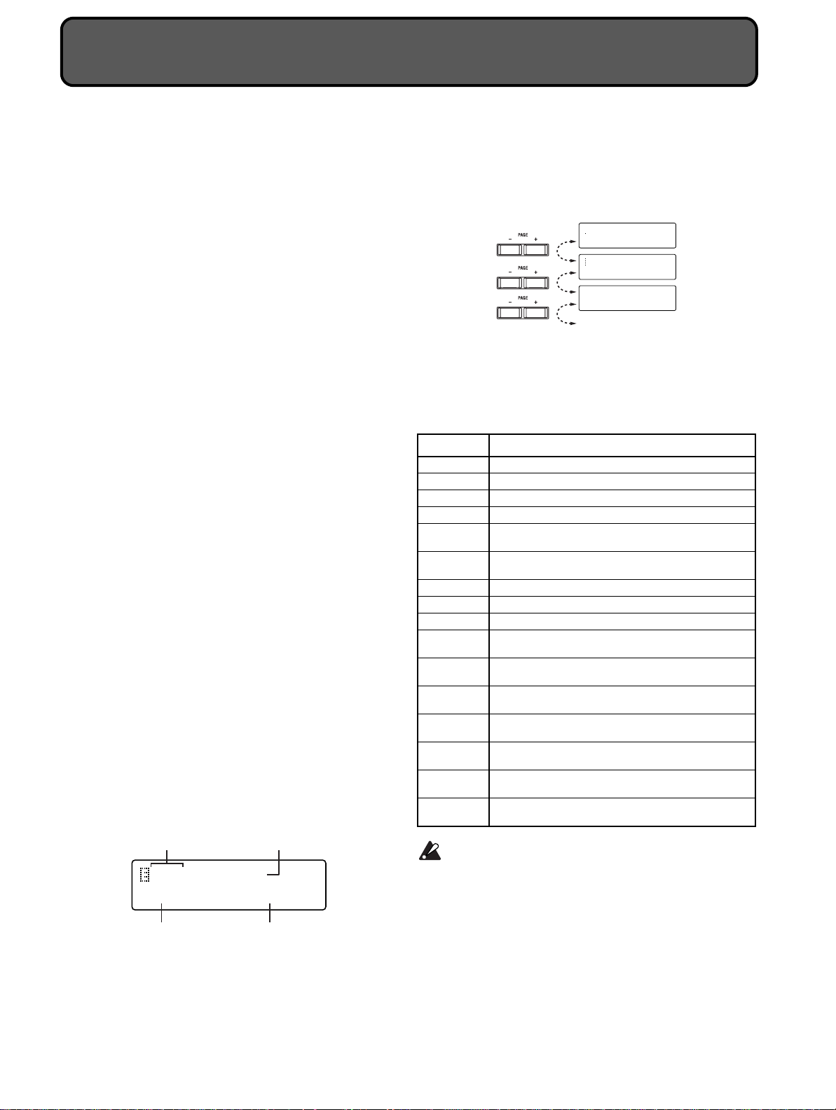
b. Select a page
LCD Edit mode consists of multiple pages. Use the PAGE
[+][–] keys and the SELECT [1]–[16] keys to select pages.
● Press the PAGE [+] or [–] key.
Each time you press the key, the next or previous page
will appear.
01A COMMON
Mode: Single
02A NAME
MS2000/R
03A VOICE
Assign: Poly
● Press a SELECT [1]–[16] key
You will move directly to the page of the desired parameter.
The SELECT [1]–[16] keys correspond to pages as shown
below.
Key Page
SELECT [1] Page01A: COMMON “Mode”
SELECT [2] Page03A: VOICE “Assign”
SELECT [3] Page04A: PITCH “Transpose”
SELECT [4] Page05A: OSC 1 “Wave”
SELECT [5]
SELECT [6]
SELECT [7] Page09A: AMP “Level”
SELECT [8] Page10A: EG 1 “Attack”
SELECT [9] Page12A: LFO 1 “Wave”
SELECT [10]
SELECT [11]
SELECT [12]
SELECT [13]
SELECT [14]
SELECT [15]
SELECT [16]
There are some pages to which the SELECT [1]–[16]
keys do not correspond. To access such a page, use the
SELECT [1]–[16] keys in conjunction with the PAGE
[+][–] keys. For example if you wish to access Page
11A: EG 2 “Attack” in the LCD screen, press the
SELECT [8] key and then press the PAGE [+] key.
Page06A: OSC 2 “Wave” (Single/Dual/Split)
Page06A: AUDIO IN 2 “Gate Sense” (Vocoder)
Page08A: FILTER “Type” (Single/Dual/Split)
Page08A: FILTER “Formant Shift” (Vocoder)
Page14A: PATCH 1 “Source: Dest” (Single/Dual/Split)
Page14A: CH LEVEL “CH: Level” (Vocoder)
Page18A: SEQ COMMON “Last STEP” (Single/Dual/Split)
Page15A: CH PAN “CH: Pan” (Vocoder)
Page22A: MOD FX “Type” (Single/Dual/Split)
Page16A: MOD FX “Type” (Vocoder)
Page23A: DELAY FX “Type” (Single/Dual/Split)
Page17A: DELAY FX “Type” (Vocoder)
Page24A: EQ “LowEQFreq” (Single/Dual/Split)
Page18A: EQ “LowEQFreq” (Vocoder)
Page25A: ARPEGGIO “Type” (Single/Dual/Split)
Page19A: ARPEGGIO “Type” (Vocoder)
Page26A: UTILITY “InitProgram” (Single/Dual/Split)
Page20A: UTILITY “InitProgram” (Vocoder)
18
Page 25
Basic Guide
A01:MS2000/R
== COMPARE ==
01A COMMON
WR Prog:A01 OK?
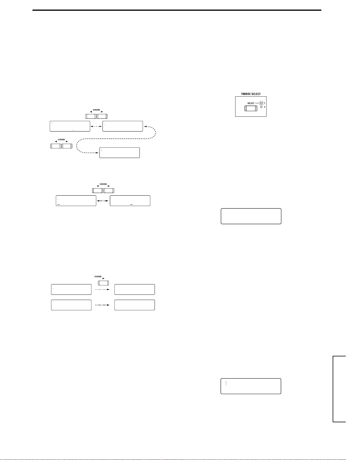
c. Select a parameter
If Global mode Page 2C: Memory “Page Jump” is turned
ON, operating a front panel knob in LCD Edit mode will
cause the LCD screen to jump automatically to that parameter. (With the factory settings, this is ON.)
● Press the CURSOR [√] or [®] key.
When you press the key, the parameter will change. The
cursor will blink at the beginning of the parameter
value.
If the parameter no longer changes when you press the
CURSOR [®] key, you have reached the last parameter
in that page.
01A COMMON
Mode: Single
If there are two parameters in a single screen, use the
CURSOR[√][®] keys to move the cursor to the parameter that you wish to modify.
In some cases, the setting of one parameter may cause
the number of parameters in the page to change.
For example if the Page 01A: COMMON “Mode”
parameter is set to Split instead of Single, there will be
two additional parameters: “Timbre Voice” and “Split
Point.” In conjunction with this, the alphabetical character following the page number will also change. (In the
case of Single, Page 01B: COMMON will be “Scale.” In
the case of Split, Page 01B: COMMON will be “Timbre
Voice.”)
01A COMMON
Mode: Single
01A COMMON
Mode: Split
d. Input the value
● Use the front panel knobs or keys, or the [+/YES]
[–/NO] keys to input the value.
Normally you will use the front panel knobs and keys.
If the parameter has no corresponding knob or key, or if
you wish to edit the setting in detail, you can use the [+/
YES] [–/NO] keys.
Each time you press the [+/YES] [–/NO] keys, the value
will increase or decrease in steps of one.
If you hold down the [+/YES] key and press the [–/NO]
key, the value will increase in steps of ten.
If you hold down the [–/NO] key and press the [+/YES]
key, the value will decrease in steps of ten.
e. Return to Program Play mode
● Press the [EXIT] key.
You will return to Program Play mode.
14A PATCH1
EG 1 >Pitch
01B COMMON
Scale:Equal Temp
01C COMMON
Scale Key: C
14A PATCH1
EG 1 >Pitch
01B COMMON
Scale:Equal Temp
01B COMMON
Timbre Voice:2+2
3. Switching timbres
For a program whose voice mode is Dual/Split, you can
select the timbre that you wish to edit.
● Press the TIMBRE SELECT [SELECT] key.
The LED of the selected timbre will light. Each time you
press the key, the timbre will change.
The front panel knobs and keys and the parameters
shown in the LCD screen will apply to the selected timbre.
4. Returning to the state before editing (Compare)
While editing a program, you can temporarily return to the
settings that were written before you edited them.
1 While holding down the [EDIT] key, press the [EXIT]
key.
The lower line of the LCD screen will indicate “COMPARE” and you will return to the state of the settings
before they were edited. The upper line of the display
will indicate the program number and program name.
2 Press the [EXIT] key.
You will return to Program Play mode.
5. Writing (saving) an edited program
If you turn off the power or change to a different program
without saving your edited program or arpeggiator settings, they will be lost. To save a program, you must perform the Write operation.
Before you begin the Write process, turn the Global mode
Page 2A: Memory “Protect” setting OFF (with the factory
settings this is ON). (☞p.30 “1. Defeat memory protect”)
1 In Program Play mode or LCD Edit mode, press the
[WRITE] key.
The upper line of the LCD will continue to show what
had been displayed when you pressed [WRITE] key. (In
the figure below, the [WRITE] key was pressed in LCD
Edit mode Page 01A: COMMON.)
The lower line of the LCD will indicate the writing destination program number (the number of the program
that you edited).
If you decide to cancel the Write operation, press the
[EXIT] key.
2 Use the [+/YES] [–/NO] keys to select the writing desti-
nation program number.
If you do not need to change the writing destination,
proceed to step 3.
IntroductionFront and rear panelConnectionsPlayingEditing
19
Page 26

3 Press the [WRITE] key.
05B OSC 1
Control 1: 000
05C OSC 1
Control 2: 060
The display will ask you for confirmation.
4 Press the [WRITE] key once again.
When the LCD screen indicates “Completed,” the data
has been written.
Never turn off the power during the Write operation.
This can damage the data.
5 Press the [EXIT] key.
You will return to the screen where you started.
Editing a synth program
Here is the procedure for editing a synth program.
Unless otherwise specified, this is the procedure for editing a
program whose voice mode is Single.
The explanation assumes that you are already in LCD Edit
mode.
1. Specify how notes will be sounded
In Page 03A: VOICE “Assign,” specify how the timbre will
sound the notes.
● Press the SELECT [2] key.
The LCD screen will show Page 03A: VOICE “Assign.”
b. Set waveform parameters
1 Rotate the [CONTROL 1] knob.
The LCD screen will show Page 05B: OSC 1 “Control 1.”
The parameter will depend on the selected waveform.
The waveforms and parameters correspond as follows.
WAVE CONTROL1
Modify waveform
Modify waveform
Modify waveform
Cross modulation amount
VOX WAVE Modify waveform
DWGS ––––––––––––––––––––––––––––––––––––
NOISE Cutoff of the LPF inside the oscillator
AUDIO IN Volume balance of AUDIO IN 1 and AUDIO IN 2
For details on the parameters, refer to the parameter
guide.
2 Rotate the [CONTROL 2] knob.
The LCD screen will show Page 05C: OSC 1 “Control 2.”
The parameter will depend on the waveform selected
for “Wave.”
03A VOICE
Assign: Mono
Use the [+/YES] [–/NO] keys to change the setting.
If you wish to play chords, select Poly. If you wish to
play single notes, select Mono or Unison.
2. Make oscillator settings
Make settings for oscillator 1 and 2, which will be the basis
of the sound.
a
b
e
a. Select the waveform for oscillator 1
● Press the OSCILLATOR 1 [WAVE] key.
Each time you press the key, the waveform will change,
and the LED for the selected waveform will light. For
oscillator 1 you can choose from eight waveforms
including the external output waveform.
d
c
f
The waveforms and parameters correspond as follows.
WAVE CONTROL2
Depth of LFO1 modulation
Depth of LFO1 modulation
Depth of LFO1 modulation
Depth of LFO1 modulation
VOX WAVE Depth of LFO1 modulation
DWGS Select DWGS waveform (64 types)
NOISE Resonance of LPF inside the oscillator
AUDIO IN Depth of LFO1 modulation
For details on the parameters, refer to the parameter
guide.
c. Select the oscillator 2 waveform
● Press the OSCILLATOR 2 [WAVE] key
The waveform will change each time you press the key,
and the LED of the selected waveform will light. For
oscillator 2, you can select from three waveforms.
The most common way to use this is to select the same
waveform as for oscillator 1, and change the pitch to add
depth to the sound.
d. Select the modulation type for the oscillator
● Press the [OSC MOD] key.
Each time you press the key, the modulation type will
change, and the LED for the selected modulation type
will light. Including a setting of “off,” you can select
from four modulation types.
20
Page 27

Basic Guide
08B FILTER
Cutoff: 060
08C FILTER
Resonance: 045
08D FILTER
EG 1 Int: +40
e. Adjust the pitch of oscillator 2 in semitone units
● Rotate the [SEMITONE] knob.
The LCD screen will show Page 06C: OSC 2 “Semitone.”
The most common way to use this is to set oscillator 2
one or two octaves lower than the pitch of oscillator 1.
06C OSC 2
Semitone: -12
f. Adjust the pitch of oscillator 2
● Rotate the [TUNE] knob.
The LCD screen will show Page 06D: OSC 2 “Tune.”
By slightly skewing the pitch to create a detuning effect,
you can give the sound more depth.
06D OSC 2
Tune: +06
3. Set the volume of each oscillator
a
b
4. Make filter settings
bc
IntroductionFront and rear panelConnectionsPlayingEditing
d
a
a. Select the filter type
● Press the [FILTER TYPE] key.
Each time you press the key, the filter type will change,
and the LED of the selected filter type will light.
The filter type will have a major impact on the character
of the sound.
b. Adjust the brightness of the sound
● Rotate the FILTER [CUTOFF] knob.
The LCD screen will show Page 08B: FILTER “Cutoff.”
Rotating the knob toward the right (increasing the
value) will brighten the sound.
a. Adjust the volume of oscillator 1
● Rotate the MIXER [OSC1] knob.
The LCD screen will show Page 07A: MIXER “OSC 1
Level.”
07A MIXER
OSC 1 Level: 127
b. Adjust the volume of oscillator 2
● Rotate the MIXER [OSC2] knob.
The LCD screen will show Page 07B: MIXER “OSC 2
Level.”
07B MIXER
OSC 2 Level: 100
c. Adding character to the sound
● Rotate the FILTER [RESONANCE] knob.
The LCD screen will show Page 08C: FILTER “Resonance.”
Rotating the knob toward the right (increasing the
value) will dramatically change the character of the
sound.
The resonance effect will also be significantly affected by
the filter type and cutoff settings.
d. Adjusting the depth of the effect from EG1
EG1 changes the filter cutoff over time. “EG 1 Int” adjusts
the depth of this effect.
● Rotate the FILTER [EG 1 INT] knob.
The LCD screen will show Page 08D: FILTER “EG 1 Int.”
Rotating the knob to the right of center (+ values) will
cause the effect to be applied to the cutoff in the positive
(+) direction.
Rotating the knob to the left of center (– values) will
cause the effect to be applied to the cutoff in the negative
(–) direction.
21
Page 28

5. Specify time-varying change in the tone
10D EG1
Release: 000
09A AMP
Level: 127
09B AMP
Panpot: CNT
Use EG 1 to create time-varying change in the cutoff frequency (FILTER “Cutoff”).
If you wish to use the front panel knobs to adjust the
EG 1 parameters, use the SEQ EDIT [SELECT] key to
make the SEQ 1–3 LED’s go off.
Note on
Note off
c
d. Adjust the speed at which the tone will change after
the note is released
● Rotate the EG 1 [RELEASE] knob.
The LCD screen will show Page 10D: EG 1 “Release.”
Rotating the knob toward the right will make the sound
change more slowly, and rotating it toward the left will
make it change instantly.
Cutoff
a: Attack Time c: Sustain Level
b: Decay Time d: Release Time
a b c d
b
a
d
Time
a. Adjust the speed at which the tone will change dur-
ing the attack
● Rotate the EG 1 [ATTACK] knob.
The LCD screen will show Page 10A: EG 1 “Attack.”
Rotating the knob toward the right will cause the tone to
change more slowly, and rotating it toward the left will
cause the tone to change instantly.
10A EG 1
Attack: 000
If rotating the knob does not produce an effect, try
adjusting the FILTER [EG 1 INT] knob, or make sure
that the SEQ EDIT SEQ 1–3 LED’s are dark. If these
LED’s are lit, it is not possible to edit the EG or LFO.
The knobs will function to edit the sequence data.
6. Adjust the output of the timbre
a
b
c
d
a. Adjust the volume of the timbre
● Rotate the [LEVEL] knob.
The LCD screen will show Page 09A: AMP “Level.”
If the volume changes over time, this level will be the
maximum level that occurs during the change in volume.
b. Adjust the speed at which the tone will change dur-
ing the decay
● Rotate the EG 1 [DECAY] knob.
The LCD screen will show Page 10B: EG 1 “Decay.”
Rotating the knob toward the right (increasing the
value) will cause a longer decay time until the sustain
level is reached.
c. Adjust the brightness of the sustained sound
● Rotate the EG 1 [SUSTAIN] knob.
The LCD screen will show Page 10C: EG 1 “Sustain.”
The change in brightness produced by the [SUSTAIN]
knob will depend on the setting of the [EG 1 INT] knob.
22
10B EG 1
Decay: 030
10C EG 1
Sustain: 060
b. Adjust the output panpot (stereo position)
● Rotate the [PAN] knob.
The LCD screen will show Page 09B: AMP “Panpot.”
When the knob is in the center (CNT), the output will be
centered.
c. Select the envelope source for the volume
● Press the [EG 2 /GATE] key.
Each time you press the key, the envelope source will
change.
If you want the volume change over time, select EG 2
([EG 2/GATE] key LED dark).
If you want the volume to sound at a fixed level, as on
an organ, select GATE ([EG 2/GATE] key LED lit).
Page 29

Basic Guide
11A EG 2
Attack: 000
11B EG 2
Decay: 021
11C EG 2
Sustain: 090
d. Apply distortion to the output
● Press the [DISTORTION] key.
Each time you press the key, distortion will be turned
on/off.
When this is on ([DISTORTION] key LED lit), distortion
will be applied. This is effective when you wish to produce a hard\ harsh tone.
If distortion is turned on, use the MIXER knobs to adjust
the degree of distortion.
If you adjust FILTER “Cutoff” or “Resonance,” the character of the distortion will change.
e. Use keyboard playing dynamics to vary the volume
● Press the SELECT [7] key, and then press the CURSOR
[®] key four times.
The LCD screen will show Page 09E: AMP “Vel Sense.”
Use the [+/YES] [–/NO] keys to set the value.
Positive (+) values will cause the volume to increase as
you play more strongly.
Negative (–) values will cause the volume to decrease as
you play more strongly.
09E AMP
Vel Sense: +30
f. Vary the volume by the keyboard location you play
● From the “Vel Sense” screen, press the CURSOR[®]
key.
The LCD screen will show Page 09F: AMP “KBD Track.”
Use the [+/YES] [–/NO] keys to set the value.
Positive (+) values will cause the volume to increase as
you play upward on the keyboard, and decrease as you
play downward on the keyboard.
Negative (–) values will cause the volume to increase as
you play downward on the keyboard, and decrease as
you play upward on the keyboard.
09F AMP
KBD Track: +25
7. Specify time-variant changes in volume
EG 2 produces time-variant changes in the AMP “Level.”
If you wish to use the front panel knobs to adjust the
EG 2 parameters, you must first use the SEQ EDIT
[SELECT] key to make the SEQ 1–3 LED’s go dark.
Level
Note on
b
a
a: Attack Time c: Sustain Level
b: Decay Time d: Release Time
a b c d
a. Adjust the speed at which the sound will attack\
trigger
● Rotate the EG 2 [ATTACK] knob.
The LCD screen will show Page 11A: EG 2 “Attack.”
Rotating the knob toward the right (increasing the
value) will cause the sound to attack/ trigger more
slowly, and rotating it toward the left (decreasing the
value) will cause the sound to attack/ trigger instantly.
If rotating the knob does not produce an effect, make
sure that the AMP [EG 2/GATE] key LED is dark.
b. Adjust the speed at which the volume will decay
● Rotate the EG 2 [DECAY] knob.
The LCD screen will show Page 11B: EG 2 “Decay.”
Rotating the knob toward the right (increasing the
value) will cause a longer decay time until the sustain is
reached.
Note off
c
time
d
IntroductionFront and rear panelConnectionsPlayingEditing
c. Adjust the volume of the sustained sound
● Rotate the EG 2 [SUSTAIN] knob.
The LCD screen will show Page 11C: EG 2 “Sustain.”
Rotating the knob toward the right (increasing the
value) will produce a louder volume during the sustain.
23
Page 30
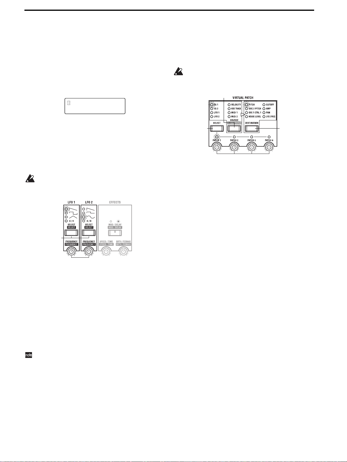
d. Adjust the speed at which the volume will decay
after the note is released
● Rotate the EG 2 [RELEASE] knob.
The LCD screen will show Page 11D: EG 2 “Release.”
Rotating the knob toward the right (increasing the
value) will make the volume decay more slowly, and
rotating it toward the left (decreasing the value) will
shorten the decay.
For sounds such as pads, strings or organs use a higher
value.
11D EG 2
Release: 000
9. Apply modulation to parameters (Virtual Patch)
Virtual Patch allows eight modulation sources to be
assigned to various parameters that make up the sound, in
order to modulate the corresponding parameters.
If you wish to use the front panel knobs to set or adjust
the Virtual Patch parameters, you must first use the
SEQ EDIT [SELECT] key to turn off the SEQ 1–3 LED’s.
b
8. Make LFO settings
The LFO (Low Frequency Oscillator) applies cyclic change
to a parameter. If it is applied to the pitch of the oscillator,
the result is vibrato. If applied to the filter cutoff, the result
is wah. If applied to the amp level, the result is a tremolo
effect.
If you wish to use the front panel knobs to adjust the
LFO parameters, you must first use the SEQ EDIT
[SELECT] key to turn off the SEQ 1–3 LED’s.
a
b
a. Select the LFO waveform
● Press the [SELECT] key.
Each time you press the key, the waveform will change
and the LED of the selected waveform will light.
The type of change will depend on the waveform you
select.
b. Set the frequency of the LFO
● Rotate the [FREQUENCY] knob.
Rotating the knob toward the right (increasing the
value) will speed up the frequency of change.
You can synchronize the LFO frequency to the tempo
specified by the [TEMPO] knob. Refer to the Parameter
Guide, Program parameters p.41.
a
d
c
a. Select a patch
● Press the [SELECT] key to select a patch.
Each time you press the key, you will cycle through
PATCH 1–4, and the LED of the selected patch will light.
b. Select a modulation source
● Press the [SOURCE] key.
Each time you press the key, the modulation source will
change and the LED of the selected modulation source
will light.
For details on the parameters, refer to the Parameter
Guide, Program parameters p.42.
c. Select the parameter to which modulation will be
applied
● Press the [DESTINATION] key.
Each time you press the key, the parameter will change
and the LED of the selected parameter will light.
For details on the parameters, refer to the Parameter
Guide, Program parameters p.42.
d. Set the depth of modulation.
● Use the [PATCH 1–4] knobs to set the depth of modu-
lation.
Rotate the knob for the patch that is selected by the
[SELECT] key.
Rotating the knob toward the right of center (+ values)
will apply the effect in the positive (+) direction.
Rotating the knob toward the left of center (– values)
will apply the effect in the negative (–) direction.
24
Page 31

Basic Guide
19A SEQ 1
Knob:None
19A SEQ 1
Knob:Cutoff
10. Make MOD SEQUENCE settings
a. Set SEQ COMMON parameters
As preparation before creating the actual sequence data,
the SEQ COMMON parameters are used to specify things
such as the maximum number of steps in the sequence and
the playback method. Use the [+/YES] [–/NO] keys to set
the values.
1 Press the SELECT [11] key.
The LCD screen will show Page 18A: SEQ COMMON
“Last Step.”
Specify the length (maximum number of steps) of the
sequence that you wish to record, in the range of 1–16.
18A SEQ COMMON
Last Step: 16
2 Press the CURSOR [®] key.
The LCD screen will show Page 18B: SEQ COMMON
“Seq Type.”
Specify the direction in which the steps will play back.
18B SEQ COMMON
Seq Type:Forward
3 Press the CURSOR [®] key.
The LCD screen will show Page 18C: SEQ COMMON
“Run Mode.”
Specify the loop setting for sequence playback.
18C SEQ COMMON
Run Mode:Loop
b. Specify sequence data for each step
Here’s how to select a program for which sequence is
turned on, and record sequence data for each step.
1 In Program Play mode, select a program for which
sequence is turned on.
2 Press the [EDIT] key.
You will enter LCD Edit mode.
3 Press the SEQ EDIT/CH PARAM [SELECT] key to
make the SEQ 1 LED light.
The LCD screen will show Page 19A: SEQ 1 “Knob.”
For this example, we will assign FILTER “Cutoff” to
SEQ1.
4 Press the [+/YES] key to set “Knob” to Cutoff.
If you wish to assign a parameter to SEQ 2 or SEQ 3, use
the [SELECT] key to select SEQ 2 or SEQ 3.
5 Press the MOD SEQUENCE [ON/OFF] key.
The [ON/OFF] key LED will light, and the sequence
will be turned on.
IntroductionFront and rear panelConnectionsPlayingEditing
4 Press the CURSOR [®] key.
5 Press the CURSOR [®] key.
The LCD screen will show Page 18D: SEQ COMMON
“Key Sync.”
Specify how the sequence will be reset when a note-on
occurs.
18D SEQ COMMON
Key Sync:Timbre
The LCD screen will show Page 18E: SEQ COMMON
“Resolution.”
Specify the playback speed of the sequence relative to
the internal clock.
18E SEQ COMMON
Resolution: 1/48
6 Press and hold a note on the keyboard.
The program will sound, and the SELECT [1]–[16] keys
will light consecutively.
7 While listening to the sound, use the sixteen knobs
located beside the SEQ EDIT LED to specify the
sequence data for each step.
The sixteen knobs are normally used to edit program
sounds (EG or LFO etc.), but when the [SELECT] key
has selected a sequence, they are used to set and edit
sequence data.
The numbers shown below each knob correspond to the
sequence steps. Rotate the knob for the step you wish to
set.
When you rotate a knob, the LCD screen will show 19C:
SEQ 1 “Step Value.”
19C SEQ 1
Step[01]: +10
Step Number
Value
The value of each step is the amount of change relative
to the parameter value that is currently written or set.
25
Page 32

If you wish to set the value in more detail, use the [+/
22A MOD FX
Type: Cho/Flg
22B MOD FX
LFO Speed: 033
22C MOD FX
Depth: 025
YES] [–/NO] keys.
If you specify a value for a step number that is beyond
the Page 18A: SEQ COMMON “Last Step” setting, it
will be ignored.
You can use the above procedure to edit sequence data
that was created previously or that was recorded in realtime.
c. Record sequence data in realtime (Motion Rec)
Motion Rec allows realtime knob movements to be
recorded in the steps of a sequence.
Here we will explain how to record movements of the FILTER [CUTOFF] knob in a program for which sequence data
has not yet been recorded.
1 In Program Play mode, select a program for which
sequence is turned off.
Select a program for which changes in tone can be heard
clearly.
2 Press the MOD SEQUENCE [ON/OFF] key to turn on
the sequence.
3 Press the SEQ EDIT/CH PARAM [SELECT] key to
select a sequence (SEQ 1–3).
For this example, select SEQ 1.
4 Press the MOD SEQUENCE [REC] key.
You are ready to record. The [REC] key LED will blink,
and the SELECT [1]–[16] keys will light consecutively.
It is not possible to enter record-ready mode unless a
sequence has been selected.
5 Rotate the ARPEGGIATOR [TEMPO] knob to adjust
the speed of the sequence.
Watch the speed at which the SELECT [1]–[16] keys
light, and adjust the speed so that you will be able to
record comfortably.
6 While playing the keyboard, rotate the FILTER [CUT-
OFF] knob.
Editing effect parameters
The MS2000/MS2000R contains modulation, delay, and
equalizer effects. Here we will explain how to make settings
for the modulation effect and the delay.
If you wish to use the front panel knobs to adjust the
parameters of the modulation effect and delay, you
must first use the SEQ EDIT [SELECT] key to turn off
the SEQ 1–3 LED’s.
1. Modulation effect settings
If you wish to use the front panel knobs to make modulation effect settings, you must first turn off the
[MOD/DELAY] key LED.
a. Select the effect type
● Press the SELECT [12] key.
The LCD screen will show Page 22A: MOD FX “Type.”
Use the [+/YES] [–/NO] keys to select the effect type.
There are three types of modulation effect.
b. Adjust the modulation frequency
● Rotate the [SPEED/TIME] knob.
The LCD screen will show Page 22B: MOD FX “LFO
Speed.”
As you rotate the knob toward the right (increasing the
value), the modulation frequency will become faster.
Recording will begin from the step at which you rotated
the knob.
When recording begins, the [REC] key LED will change
from blinking to lit.
When you record to the step that was specified by “Last
Step,” the [REC] key LED will go dark, and recording
will end.
While playing the keyboard, listen to the tonal change. If
you are not satisfied, you can either press the [REC] key
once again and re-record, or use the sixteen knobs to edit
individual steps.
If you wish to keep the recorded settings, perform the
Write procedure. (☞p.19 “5. Writing (saving) an edited
program”)
If two or more knobs are rotated, the knob that was
rotated first will be recorded.
It is not possible to record the ARPEGGIATOR or
EFFECTS knobs.
26
c. Adjust the effect depth and the amount of feedback
● Rotate the [DEPTH/FEEDBACK] knob.
The LCD screen will show Page 22C: MOD FX “Depth.”
Increasing the value will cause modulation to be deeper,
increasing the amount of feedback.
Page 33

Basic Guide
25E ARPEGGIO
Target: Timbre 1
25F ARPEGGIO
Key Sync: OFF
25G ARPEGGIO
Resolution: 1/4
25H ARPEGGIO
Swing: +050[%]
2. Delay settings
If you wish to use the front panel knobs to set the
delay, you must first turn on the [MOD/DELAY] key
LED.
a. Select the delay type
● Press the SELECT [13] key.
The LCD screen will show Page 23A: DELAY FX “Type.”
Use the [+/YES] [–/NO] keys to select the delay type.
There are three types of delay.
23A DELAY FX
Type:StereoDelay
b. Adjust the delay time
● Rotate the [SPEED/TIME] knob.
The LCD screen will show Page 23C: DELAY FX “Delay
Time.”
Rotating the knob toward the right (increasing the
value) will lengthen the delay time.
23C DELAY FX
Delay Time: 000
You can synchronize the delay time to the tempo specified by the [TEMPO] knob. ☞Parameter guide p.44,
Page 23B: DELAY FX “Tempo Sync.”
c. Adjust the effect depth and the amount of feedback
● Rotate the [DEPTH/FEEDBACK] knob.
The LCD screen will show Page 23E: DELAY FX
“Depth.”
Rotating the knob toward the right (increasing the
value) will deepen the delay sound, increasing the
amount of feedback.
23E DELAY FX
Depth: 000
Editing arpeggio parameters
Here we will explain the parameters that can be set only in
LCD Edit mode.
Use the [+/YES] [–/NO] keys to set the values.
For details on the parameters that can be set in Program Play
mode, refer to the section of the Basic Guide entitled Playing,
in “Playing arpeggios – 2. Using the knobs and keys to modify the settings” (☞p.15).
a. Select the timbre that will be used to play the arpeg-
gio (Dual/Split only)
● Press the SELECT [15] key, and then press the CUR-
SOR[®] key four times.
The LCD screen will show Page 25E: ARPEGGIO “Target.”
Select the timbre that will be used to play the arpeggio
when the voice mode is Dual or Split. (This will be displayed only for Dual or Split.)
b. Specify the keyboard synchronization
● Press the CURSOR [®] key.
The LCD screen will show Page 25F: ARPEGGIO “Key
Sync.”
If this is turned ON, the arpeggio pattern will begin
playing from the beginning whenever a note-on occurs.
c. Set the resolution
● Press the CURSOR [®] key.
The LCD screen will show Page 25G: ARPEGGIO “Resolution.”
Set the resolution (timing interval between notes) relative to the tempo of the arpeggio playback.
IntroductionFront and rear panelConnectionsPlayingEditing
d. Make the rhythm swing
● Press the CURSOR [®] key.
The LCD screen will show Page 25H: ARPEGGIO
“Swing.”
This setting skews the timing so that the arpeggiator
will offset the even-numbered notes, giving you a swing
feel.
27
Page 34

Editing vocoder program
08F FILTER
E.F.Sense: 050
08A FILTER
Cutoff: +00
Here’s the procedure for editing a program when in the
Vocoder mode.
For details on parameters that are the same as the synth program, please refer to the explanation for synth programs.
Here we will explain the parameters that can be set only for
a vocoder program.
1. Adjust the mic input audio
b
a
2. Set the filter
c
a
b
a. Adjust the sensitivity of the ENVELOPE FOLLOWER
for the modulator
● Rotate the [ ] knob.
The LCD screen will show Page 08F: FILTER
“E.F.Sense.” Rotating the knob toward the right (increasing the value) will smooth the attack of the vocoder output, and lengthen the release.
a. Cut the noise when there is no input
1 Rotate the [ ] knob.
The LCD screen will show Page 06B: AUDIO IN 2
“Threshold.”
Rotating the knob toward the right will make it more
likely that the audio will be cut.
Adjust this so that noise is not obtrusive when you are
not speaking into the mic.
06B AUDIO IN 2
Threshold: 069
2 Press the SELECT [5] key.
The LCD screen will show Page 06A: AUDIO IN 2 “Gate
Sense.”
Adjust this so that the vocoder sound that is output is
not interrupted unnaturally. Use the [+/YES] [–/NO]
keys to adjust the value.
06A AUDIO IN 2
Gate Sense: 100
b. Adjust the consonants of the vocoder sound
● Rotate the [ ] knob.
The LCD screen will show Page 06C: AUDIO IN 2 “HPF
Level.”
Rotating the knob toward the right (increasing the
value) will emphasize the consonants of the input
sound.
b. Shift the cutoff frequency of the carrier filters
● Press the [ ] key.
When you press the key, the formant shift amount will
change, and the LED for the selected shift amount will
light.
By shifting the filters, you can dramatically change the
character of the vocoder output.
c. Adjust the cutoff frequency of the carrier filters
● Rotate the FILTER [ ] knob.
The LCD screen will show Page 08B: FILTER “Cutoff.”
Use the [ ] knob to adjust the filter shift amount
in a range of ±2 steps.
By using this in conjunction with the [ ] key,
the cutoff frequency can be shifted in a range of ±4 steps.
d. Adjust the output level of the carrier filters
1 Press the [ ] key to make the
LED light.
28
06C AUDIO IN 2
HPF Level: 100
Page 35

Basic Guide
2 Use the sixteen knobs located beside to
adjust the output level of each filter.
Rotating the knob far left is a setting of 0, and rotating it
far right is a setting of 127 (max).
f. Adjust the panpot (stereo location) of the carrier fil-
ters
1 Press the [ ] key to make the
LED light.
2 Use the sixteen knobs located beside to
adjust the panpot of each filter.
When the knob is in the center (CNT), the output will be
in the center. When rotated far left, the output will be
only in the L channel. When rotated far right, the output
will be only in the R channel.
Changing the program name
a. Using the CURSOR [√] [®] keys and the [+/YES]
[–/NO] keys
1 Press the SELECT [1] key, and then press the PAGE [+]
key.
The LCD screen will show Page 02A: NAME.
● While pressing the [EDIT] key, rotate knobs 1–12.
The corresponding character (1–12) of the name will
change.
● While pressing the [EDIT] key, rotate knob 13.
Uppercase alphabetical characters can be selected for the
character at the cursor location.
● While pressing the [EDIT] key, rotate knob 14.
Lowercase alphabetical characters can be selected for the
character at the cursor location.
● While pressing the [EDIT] key, rotate knob 15.
Numerals can be selected for the character at the cursor
location.
● While pressing the [EDIT] key, rotate knob 16.
Symbols (including a space) can be selected for the character at the cursor location.
c. Deleting a character
1 Use the CURSOR[√][®] keys to move the cursor to
the character that you wish to delete.
2 Hold down the [EDIT] key, and press the CURSOR
[√] key.
The character at the cursor will be deleted.
d. Inserting a character
A character can be inserted if no more than eleven characters have already been specified, and if there is a space at
the end of the character string.
1 Use the CURSOR[√][®] keys to move the cursor to
the location where you wish to insert a character.
2 Hold down the [EDIT] key, and press the CURSOR
[®].
A character will be inserted at the cursor location. The
inserted character will be the last-deleted character. If
you are inserting a character for the first time, it will be a
space.
IntroductionFront and rear panelConnectionsPlayingEditing
02A NAME
MS2000/R
2 Use the CURSOR[√][®] keys to move the cursor to
the character that you wish to change.
3 Use the [+/YES] [–/NO] keys to select the desired char-
acter.
4 Repeat steps 2 and 3 to specify the desired program
name.
You can specify a program name of up to 12 characters.
b. Using the [EDIT] key and the sixteen knobs
When the LCD screen shows Page 02A: NAME, you can
use the [EDIT] key and the sixteen knobs (used for
sequence and vocoder settings) to change the program
name as explained below.
29
Page 36

Editing Global parameters
2A MEMORY
Protect:ON
2A MEMORY
Protect:OFF
In Global mode you can make settings that affect the entire
MS2000/MS2000R, and also create user scales.
Basic editing procedure
a. Enter Global mode
● Press the [GLOBAL] key.
You will enter Global mode. The upper line of the LCD
screen will show the page number and page name, and
the lower line will show the parameter name and
parameter value.
Page number
1A GLOBAL
Mst.Tune:440.0Hz
Page name
e. Write (save) the Global parameters
Global parameters that you edit will revert to their
unedited state if you turn off the power without saving. If
you wish to save your settings, you must perform the Write
operation.
To write Global parameters, press the [WRITE] key in Global mode.
The LCD screen will ask you for confirmation. If you wish
to write the data, press the [WRITE] key once again. To cancel the Write operation, press the [EXIT] key in the confirmation screen.
Global parameters can be saved regardless of the memory protect setting (Global mode Page 2A: MEMORY
“Protect”).
Never turn off the power during the Write operation.
This can damage the data.
Editing parameters
b. Select a page
In the same way as in LCD Edit mode, use the PAGE [+][–]
keys and SELECT [1]–[16] keys to select the desired page.
The SELECT [1]–[16] keys correspond to pages as shown
below.
Key Page
SELECT [1] Page1A: GLOBAL “Mst.Tune”
SELECT [2] Page1D: GLOBAL “Vel.Curve”
SELECT [3] Page1F: GLOBAL “AudioInThru”
SELECT [4] Page2A: MEMORY “Protect”
SELECT [5] Page3A: MIDI “MIDI Ch”
SELECT [6] Page3C: MIDI “Clock”
SELECT [7] Page3D: MIDI “MIDI1”
SELECT [8] Page3F: MIDI “MIDI Dump”
SELECT [9] Page4A: MIDI FILTER “ProgChg”
SELECT [10] Page4B: MIDI FILTER “CtrlChg”
SELECT [11] Page4C: MIDI FILTER “P.Bend”
SELECT [12] Page4D: MIDI FILTER “SystemEx”
SELECT [13] Page6A: PEDAL&SW “A.Pedal”
SELECT [14] Page6B: PEDAL&SW “A.SwFunc”
SELECT [15] Page7A: USERSCALE “Key: Detune”
SELECT [16] Page8A: CALIB (AS)
c. Select a parameter
As in LCD Edit mode, use the CURSOR[√][®] keys to
select the desired parameter. (☞p.19)
d. Input the value
● Use the [+/YES] [–/NO] keys to input the value.
When you press the [+/YES] [–/NO] keys, the value
will increase or decrease in steps of one.
If you hold down the [+/YES] key and press the [–/NO]
key, the value will increase in steps of ten.
If you hold down the [–/NO] key and press the [+/YES]
key, the value will decrease in steps of ten.
30
Parameter name
Parameter value
1. Defeat memory protect
To prevent data from being rewritten accidentally, the
MS2000/MS2000R provides a memory protect function
that disables writing to memory. In order to write edited
data, you must first turn memory protect OFF (so that writing will not be disabled).
1 Press the [GLOBAL] key.
You will enter Global mode.
2 Press the SELECT [4] key.
The LCD screen will show Page 2A: MEMORY “Protect.”
3 Press the [–/NO] to turn “Protect” OFF.
Now it will be possible to execute the write operation.
2. Restoring settings to their factory state
The factory settings are called the “preloaded data.” You can
load this preloaded data to restore the MS2000/MS2000R’s
programs and global settings to the factory state.
When you load this data, all data in the MS2000/
MS2000R will be rewritten to the factory settings.
Before you perform this operation, make sure that it is
OK to overwrite the data.
If Global mode Page 2A: MEMORY “Protect” is ON,
the preload data cannot be loaded. If you wish to load
the preload data, you must first turn “Protect” OFF.
1 Press the [GLOBAL] key.
You will enter Global mode.
2 Press the SELECT [4] key, and then press the CURSOR
[®] key three times.
The LCD screen will show Page 2D: MEMORY “Preload.”
Page 37

Basic Guide
3C MIDI
Clock:External
3F MIDI
MIDI Dump OK?
3F MIDI
1PROG
OK?
2D MEMORY
Preload OK?
3 Press the [+/YES] key.
A screen will appear in which you can select the data to
be loaded.
2D MEMORY
1PRG A01”A01 OK?
4 Use the [+/YES] [–/NO] keys to select the data that you
wish to load.
If 1PROG is selected, only a single program will be
loaded. In this case, use the [+/YES] [–/NO] keys to
select the program number to be loaded, and the loading
destination (use the CURSOR [®] key to move).
If PROG is selected, 128 programs will be loaded.
If GLOBAL is selected, Global data (the settings of Glo-
bal mode) will be loaded.
5 Use the CURSOR [®] key to move the cursor to OK?,
and press the [+/YES] key.
The screen will ask for confirmation.
2D MEMORY
Are You Sure OK?
6 Press the [+/YES] key once again.
The data will be loaded.
When the screen indicates “Completed,” loading has
been completed.
7 Press the [EXIT] key.
You will return to the screen where you begin the “Preload” process.
3. Synchronization with external MIDI devices
Settings for synchronization with a connected external
MIDI device are made in Page 3C: MIDI “Clock.”
a. Synchronizing an external MIDI device to the
MS2000/MS2000R
You can synchronize an external MIDI device such as a
sequencer or rhythm machine to the tempo of the MS2000/
MS2000R arpeggiator.
1 Use a MIDI cable to connect the MS2000/MS2000R’s
MIDI OUT connector to the external MIDI device’s
MIDI IN connector (☞p.10).
2 Press the [GLOBAL] key to enter Global mode.
3 Press the SELECT [6] key.
The LCD screen will show Page 3C: MIDI “Clock.”
3C MIDI
Clock:Internal
5 Make settings so that the external MIDI device will
receive MIDI Clock messages from another device
(i.e., so that the external MIDI device will function as a
slave device).
The external MIDI device (sequencer or rhythm
machine) will operate according to the tempo set by the
[TEMPO] knob.
b. Synchronizing the MS2000/MS2000R to an exter-
nal MIDI device
1 Use a MIDI cable to connect the MS2000/MS2000R’s
MIDI IN connector to the external MIDI device’s
MIDI OUT connector (☞p.10).
2 Press the [GLOBAL] key to enter Global mode.
3 Press the SELECT [6] key.
The LCD screen will show Page 3C: MIDI “Clock.”
4 Use the [+/YES] [–/NO] keys to select External.
5 Make settings so that the external MIDI device will
transmit MIDI Clock messages (i.e., so that the external MIDI device will function as a master device).
The sequence or arpeggiator will operate according to
the tempo of the external MIDI device.
For details on synchronization settings for your external MIDI device, refer to the owner’s manual for your
device.
4. Saving data on an external device (Data Dump)
Various types of data from the MS2000/MS2000R’s internal
memory can be transmitted as MIDI exclusive data, and
saved on another connected MIDI device such as a data
filer.
Before you begin, connect a device that is able to receive a
MIDI data dump (a data filer, computer, or another
MS2000/MS2000R unit), and set the global MIDI channels
of both devices to match.
1 Press the [GLOBAL] key.
You will enter Global mode.
2 Press the SELECT [8] key.
The LCD screen will show Page 3F: MIDI “MIDI
Dump.”
3 Press the [+/YES] key.
The display will indicate the type of data dump to be
transmitted.
IntroductionFront and rear panelConnectionsPlayingEditing
4 Use the [+/YES] [–/NO] keys to select Internal.
With a setting of Internal, MIDI Clock messages will be
transmitted from the MS2000/MS2000R at the tempo
specified by the ARPEGGIATOR [TEMPO] knob.
31
Page 38

4 Use the [+/YES] [–/NO] keys to specify the data that
will be transmitted.
3F MIDI
ALL
OK?
If 1PROG is selected, only the data of the currently
selected program will be transmitted.
If PROG is selected, all program data will be transmitted.
If GLOBAL is selected, Global data will be transmitted.
If ALL is selected, all programs and Global data will be
transmitted.
5 Press the CURSOR [®] key to move the cursor to OK?
6 Press the [+/YES] key.
The screen will ask you to confirm the data transmission.
3F MIDI
Are You Sure
OK?
7 Press the [+/YES] key.
The data will be transmitted.
ALL DATA
Processing...
When the transmission is completed, the display will
indicate “Completed...”
Please do not touch the knobs, keys, keyboard, or
wheels etc. of the MS2000/MS2000R while the data is
being transmitted.
If you wish to receive a data dump on the MS2000/
MS2000R, you must first turn Global mode Page 2A:
MEMORY “Protect” OFF. If “Protect” is ON, data
dumps cannot be received.
32
Page 39

Parameter Guide
Program parametersGlobal parameters
Parameter Guide
Program parameters
Global parameters
Page 40

Program parameters
These are the parameters that make up the sound of a program.
If you wish to save a sound, you must perform the Write
operation (☞p.19, Basic Guide, Edit section “5. Writing (saving) an edited program”).
Uppercase parameter names enclosed in parentheses (
are parameters for which there is a front panel knob or key.
❮ ❯)
1. PROGRAM COMMON Parameters
These are parameters that apply to the entire program.
Page01: COMMON
A: Mode........................................... [Single...Vocoder]
This selects the voice mode of the program.
Single
When you play the keyboard, a single timbre will sound.
The program can be played with up to four voices (four
notes).
B: Timbre Voice ...................................[1+3, 2+2, 3+1]
This specifies the maximum number of notes that can be
played by each timbre.
This parameter will be displayed and can be set only if
“Mode” is Dual or Split.
1+3
Timbre 1 will play one voice, and timbre 2 will play three
voices.
2+2
Each timbre will play two voices.
3+1
Timbre 1 will play three voices, and timbre 2 will play one
voice.
If the Page 03A VOICE “Assign” setting is Mono, this
setting will be ignored.
C: Split Point................................................. [C-1...G9]
Specify the keyboard location (split point) at which timbres 1
and 2 will be divided.
You can also change this by holding down the [EDIT] key
and playing a note on the keyboard where you want the timbres to be split.
This parameter will be displayed and can be set only when
“Mode” is Split.
Timbre1
Split
Two timbres can be played on different areas of the keyboard. The number of notes that can be played on each
timbre is specified by “Timbre Voice.”
Timbre1
Split Point
Dual
Two timbres will sound simultaneously when you play the
keyboard. The number of notes that can be played on each
timbre is specified by “Timbre Voice.”
By using Page 03B: VOICE “MIDI ch” to specify a different
MIDI channel for each of the two timbres, you can use the
MS2000/MS2000R as a multi-timbral MIDI tone generator.
Timbre2
Timbre1
Vocoder
By inputting an audio signal to the AUDIO IN 2 connector,
you can use the MS2000/MS2000R as a four-voice
vocoder.
For details on the vocoder parameters, refer to p.49 “4.
Vocoder Parameters.”
Timbre2
D: Scale .................................[Equal Temp...User Scale]
This selects the scale type of the program. You can select
from ten scale types.
Equal Temp
This is the equal temperament that is used for most music.
Each semitone is spaced an equal pitch distance apart.
Pure Major
This is a pure major temperament. Major chords played in
the key specified by “Scale Key” will be perfectly in tune.
Pure Minor
This is a pure minor temperament. Minor chords played in
the key specified by “Scale Key” will be perfectly in tune.
Arabic
This is a scale used in Arabic music. It includes the quarter-tone scale used in Arabic music.
Pythagorea
This is the Pythagorean scale, which is based on ancient
Greek musical theory and is especially effective for playing melodies.
Werckmeist
This is the Werckmeister temperament, an equal-tempered
scale used in the later Baroque period.
Kirnberger
This is the Kirnberger temperament, created in the 18th
century and used mainly for tuning harpsichords.
Slendro
This is the Slendro scale, an Indonesian gamelan scale that
divides the octave into five notes. If the “Scale Key” is C,
use the C, D, F, G, and A notes.
34
Page 41

Parameter Guide
Pelog
This is the Pelog scale, an Indonesian gamelan scale that
divides the octave into seven notes. If the “Scale Key” is C,
use the C, D, E, F, G, A, and B notes
User Scale
This will be the scale that was specified in Global mode
Page 7A: User Scale.
E: Scale Key........................................................[C...B]
Specify the key (tonic) that will be the basis of the scale
selected by “Scale.”
2. NAME (Program Name)
Page02: NAME
A: Name .......................................................... [!...’]
Specify the name of the program.
Use the CURSOR[√][®] keys, the [+/YES] [–/NO] keys, the
[EDIT] key, and the sixteen knobs to specify the name.
For the procedure, refer to p.29 Basic Guide, Edit section
“Changing the program name.”
Available characters
!"#$%&'()*+,-./0123456789:;<=>?@
ABCDEFGHIJKLMNOPQRSTUVWXYZ[\]^_“
abcdefghijklmnopqrstuvwxyz{|}”’
3. SYNTH Parameters
These are the parameters for synth programs (i.e., programs
whose Page 01A: COMMON “Mode” is Single/Dual/Split).
In the case of Dual/Split, use the front panel TMIBRE
SELECT [SELECT] key to switch between the timbres for
editing.
■ VOICE
These parameters specify how the timbre will be sounded,
and set the MIDI channel.
Page03: VOICE
A: Assign .....................................[Mono, Poly, Unison]
Specify how the timbre will be sounded
Mono
The timbre will sound monophonically (single notes).
Poly
The timbre will sound polyphonically. A maximum of four
voices (notes) can be played simultaneously.
If “Mode” is Dual/Split, each timbre will sound the number of voices specified by “Timbre Voice.”
Unison
The timbre will sound in unison.
If “Mode” is Dual/Split, each timbre will apply a unison
effect with the number of voices specified by “Timbre
Voice.”
If “Mode” is Dual/Split and the maximum polyphony
of the timbre (“Timbre Voice”) has been set to 1 (note),
the timbre will sound monophonically regardless of
this setting.
B: MIDI ch ..............................................[GLB, 01...16]
Specify the MIDI transmit/receive channel of each timbre.
GLB
The global MIDI channel (set in Global mode Page 3A:
MIDI “MIDI Ch”) will be used as the MIDI transmit/
receive channel of the timbre. Select GLB if you are playing the MS2000/MS2000R from its own keyboard or from
a connected MIDI keyboard.
01...16
The specified channel will be used as the MIDI transmit/
receive channel of the timbre.
When using the MS2000/MS2000R with a connected
external MIDI sequencer, set the MIDI transmit/receive
channel of each timbre to match the MIDI channel of the
appropriate track of your MIDI sequencer.
If the channel you select is the same as the global MIDI
channel, a “G” will be displayed beside the setting.
C: Priority........................................... [Last, Low, High]
Specify which note on the keyboard will be sounded when
you simultaneously play more notes than the number of
voices specified for this timbre.
Last
The last-played note will be given priority.
Low
The lowest note on the keyboard will be given priority.
High
The highest note on the keyboard will be given priority.
D: Trigger ............................................... [Single, Multi]
Select the trigger mode.
This specifies whether retriggering will occur if you continue
holding the first-pressed note and play another note.
This parameter will be displayed and can be set only if Page
03A: VOICE “Assign” is set to Mono/Unison.
Single
The second and subsequent notes will not retrigger the EG
or LFO.
Use this setting when you wish to play legato.
Multi
The EG and LFO will be retriggered each time a note is
played.
Note on
EG
Single
Trigger
EG
Multi
Trigger
Note on
Program parameters
35
Page 42

E: Detune............................................[00cent...99cent]
Specify the amount of detuning (difference in pitch) that will
be applied to notes sounded simultaneously by the Unison
function.
This parameter will be displayed and can be set only if
“Assign” is set to Unison.
If the “Mode” is Dual/Split and the maximum polyphony (“Timbre Voice”) of the timbre is 1, this setting will
have no effect.
■ PITCH
These are the pitch-related parameters.
Page04: PITCH
A: Transpose...............................................[–24...+24]
Adjust the pitch of the oscillator in semitone (100 cent) steps.
The range is two octaves upward or downward.
Changes made by the front panel OCTAVE (or BANK/
OCTAVE) buttons actually shift the pitches assigned to
the keyboard (or keys) in one-octave steps, and do not
affect the pitch of the oscillator that is sounding. Nor are
such settings saved by the Write operation. If you wish
to change the pitch of the oscillator itself, you must use
this “Transpose” setting to specify the pitch.
B: Tune ........................................... [–50cent...+50cent]
Adjust the pitch of the oscillator in one-cent steps.
The range is –50 – +50 cents.
■ OSCILLATOR
These are the parameters that affect the waveform of the
oscillator.
Page05: OSC 1
A: Wave ❮ WAVE ❯ ..............................[Saw...Audio In]
B: Control1 ❮ CONTROL1 ❯......................... [000...127]
C: Control2 ❮ CONTROL2 ❯.........................[000...127]
“Wave” selects the waveform for OSC1 (oscillator 1).
“Control1” and “Control2” set parameters for the selected
waveform. The parameters that you set will depend on the
selected waveform.
Saw
This is a sawtooth wave, suitable for creating typical analog synthesizer sounds such as synth bass and synth brass.
• Control1
Adjusting this value will modify the waveform.
A setting of 0 will produce a conventional sawtooth
wave, and a setting of 127 will produce a sawtooth wave
one octave higher.
• Control2
LFO1 is used to apply WFM (wave form modulation) to
the waveform specified by “Control 1.” The “Control 2”
setting specifies the depth of the modulation produced
by LFO1.
By setting the Page 12A: LFO1 “Wave” parameter to
(Tr i ) and adjusting “Frequency,” you can create the
effect of detuning.
C: Vibrato Int..............................................[–63...+63]
Specify the depth of the vibrato effect that is applied when
the modulation wheel (or for the MS2000R, the modulation
wheel of a connected external MIDI device) is moved to the
maximum position.
The LFO2 will apply a vibrato effect to the pitch of the oscillator.
D: Bend Range............................................[–12...+12]
Specify the amount of pitch change in semitones that will
occur when the pitch wheel is operated. This setting specifies
the amount of pitch change that will occur when the pitch
bender is moved to the maximum positive (+) position.
E: Portamento ❮ TIME ❯ ...............................[000...127]
This specifies the speed of the portamento effect (a smooth
change in pitch from one note to the next note of a different
pitch).
With a setting of 000, there will be no portamento effect.
Increasing this setting from 001 will cause the pitch to
change correspondingly slower.
If Page 03: VOICE “Assign” is set to Mono or Unison,
and if “Trigger” is set to Single, portamento will not
apply to the first-sounded note.
0
Pulse
This is a pulse wave, suitable for electronic sounds or
wind instruments.
• Control1
This adjusts the pulse width.
A setting of 0 will produce a square wave, with a tone
reminiscent of woodwind instruments such as clarinet.
At a setting of 127 the pulse width will be 0, and no
sound will be heard.
By adjusting the pulse width you can produce sounds
similar to clavinet or sax.
• Control2
LFO1 is used to apply PWM (pulse width modulation)
to the pulse width specified by “Control1.” The
“Control2” setting specifies the depth of the modulation
produced by LFO1.
By setting the Page 12A: LFO1 “Wave” parameter to
(Tr i ) and adjusting “Frequency,” you can make the
sound distort.
0 63 127
63
127
36
Page 43
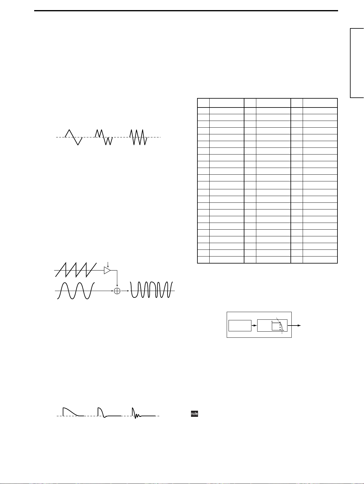
Parameter Guide
Tri
This is a triangle, which has weaker overtones and a stronger fundamental than a sawtooth wave or square wave. It
is suitable for mellow bass sounds.
• Control1
You can modify the waveform by adjusting this value.
A setting of 0 will produce a triangle wave, and a setting
of 127 will produce a waveform with a pitch that is one
octave and a fifth higher.
• Control2
LFO1 is used to apply WFM (wave form modulation) to
the waveform specified by “Control1.” The “Control2”
setting specifies the depth of the modulation produced
by LFO1.
0 63 127
Sin (Cross)
This is basically a sine wave, but oscillator 2 is used to
apply cross modulation.
By using oscillator 2 to modulate the frequency of oscillator 1, cross modulation produces a complex overtone
structure.
• Control1
Specify the depth of cross modulation.
At a setting of 0 a sine wave will be produced.
• Control2
LFO1 is used to apply further modulation to the depth
of cross modulation that was specified by “Control1.”
“Control2” specifies the depth of modulation produced
by LFO1.
X-mod Depth + X-mod Depth Mod
OSC2
OSC1
OSC1 Output
Vox Wave
This simulates a waveform similar to human vocal cords.
Even if the oscillator pitch is changed, the frequency spectrum will be maintained, which makes this effective when
used for vocal-type sounds or as a vocoder oscillator.
Select HPF or BPF as the filter, and adjust “Cutoff” to create a vocal-type sound.
• Control1
Adjusting this value will modify the waveform.
• Control2
LFO1 is used to apply modulation to the waveform
specified by “Control1.” Control2 sets the depth of the
modulation applied by LFO1.
0 63 127
DWGS
This is waveform data created by harmonic additive synthesis. 64 types of waveform are provided.
• Control1
This has no effect.
• Control2
This selects the waveform.
You can select one of the following waveforms.
DWGS List
No Name No Name No Name
1 SynSine1 24 5thWave1 47 Clav1
2 SynSine2 25 5thWave2 48 Clav2
3 SynSine3 26 5thWave3 49 Guitar1
4 SynSine4 27 Digi1 50 Guitar2
5 SynSine5 28 Digi2 51 Guitar3
6 SynSine6 29 Digi3 52 Bass1
7 SynSine7 30 Digi4 53 Bass2
8 SynBass1 31 Digi5 54 Bass3
9 SynBass2 32 Digi6 55 Bass4
10 SynBass3 33 Digi7 56 Bass5
11 SynBass4 34 Digi8 57 Bell1
12 SynBass5 35
13 SynBass6 36 E.Piano1 59 Bell3
14 SynBass7 37 E.Piano2 60 Bell4
15 SynWave1 38 E.Piano3 61 Voice1
16 SynWave2 39 E.Piano4 62 Voice2
17 SynWave3 40 Organ1 63 Voice3
18 SynWave4 41 Organ2 64 Voice4
19 SynWave5 42 Organ3
20 SynWave6 43 Organ4
21 SynWave7 44 Organ5
22 SynWave8 45 Organ6
23 SynWave9 46 Organ7
*: The 35 Endless waveform simulates an endless scale, in which notes one octave
apart have the identical pitch. You can play an ascending or descending scale as far
as you wish, producing the sensation that a scale of the same pitch is continuing
infinitely.
Endless
*
58 Bell2
Noise
This generates white noise. Within the oscillator, a LPF
(Low Pass Filter) is provided to process the noise.
Resonance
Noise
Genarator
LPF
Cutoff
• Control1
This sets the cutoff frequency of the LPF.
Adjusting this will affect the noise waveform.
• Control2
This controls the resonance of the LPF.
If you raise this enough to produce an identifiable pitch,
the cutoff frequency will move according to the keyboard location you play, and the change will be heard as
a pitch.
If you want the oscillation produced by resonance to
match the reference pitch, set “Control1” to 24.
Program parameters
37
Page 44
Audio In
If this is selected, the waveform input from the AUDIO IN
1 or AUDIO IN 2 jack will be used.
This allows the MS2000/MS2000R to be used as an effect
processor.
• Control1
This adjusts the volume balance between AUDIO IN 1
and AUDIO IN 2. With a setting of 0 only AUDIO IN 1
will be output. With a setting of 127, only AUDIO IN 2
will be output.
• Control2
LFO1 is used to apply modulation to the volume balance
between AUDIO IN 1 and AUDIO IN 2 that you set by
“Control1.” The “Control2” setting sets the depth of this
modulation produced by LFO1.
Sync
This modulation forcibly synchronizes oscillator 2 to the
phase of oscillator 1, forcibly resetting the phase of oscillator 2.
This is effective on synth lead sounds. Use “Semitone” and
“Tune” to adjust the overtones.
OSC2 Wave
Sync
OSC1 Wave
RingSync
This simultaneously applies Ring and Sync modulation.
OSC2 Wave
OSC2 Output
OSC1 Output
OSC2 Output
Page06: OSC 2
A: Wave ❮ WAVE ❯ ................................ [Saw, Squ, Tri]
Select the waveform for oscillator 2.
Saw
A sawtooth wave, suitable for creating typical analog synthesizer sounds such as synth bass and synth brass.
Squ
A square wave, suitable for creating electronic sounds or
simulating woodwinds such as clarinet.
Tri
A triangle wave, with weaker overtones and stronger fundamental than a sawtooth wave or square wave.
B: OSC Mod ❮ OSC MOD ❯...................[OFF...RingSync]
Select the modulation type for the oscillator.
OFF
Output without applying modulation. By adjusting “Semitone” and “Tune,” you can produce a spacious detuning
effect. For synth bass sounds, set the pitch of oscillators 1
and 2 one octave apart.
Ring
This modulation generates frequency components that are
the sum and difference of the oscillator 1 and 2 waveforms. By adjusting “Semitone” and “Tune” you can create
metallic sounds with little sense of pitch. This is effective
for sound effects.
OSC2 Wave
OSC2 Output
Sync
OSC1 Wave
OSC1 Output
C: Semitone ❮ SEMITONE ❯ ......................... [–24...+24]
Specify the amount of detune for OSC2 relative to OSC1, in
semitone steps.
With a value of 0, the pitch of OSC2 will be the same as
OSC1.
A setting of ±12 produces a pitch difference of one octave,
and ±24 produces a pitch difference of two octaves.
D: Tune ❮ TUNE ❯........................................ [–63...+63]
Specify the amount of detune for OSC2 relative to OSC1.
A setting of ±63 produces a pitch difference of ±2 octaves,
and ±48 produces a pitch difference of ±1 octave. A value
near 0 will make fine adjustments in the pitch.
If “OSC Mod” is set to Sync, adjustments in “Semitone”
or “Tune” will change the pitch of the overtones. The
pitch of the fundamental will not change.
■ MIXER
These parameters affect the output level of each oscillator.
These settings will be the input level to the filter.
Page07: MIXER
38
OSC1 Wave
OSC1 Output
A: OSC 1 Level ❮ OSC1 ❯............................ [000...127]
Set the output level of oscillator 1.
B: OSC 2 Level ❮ OSC2 ❯ ............................ [000...127]
Set the output level of oscillator 2.
C: Noise Level ❮ NOISE ❯............................ [000...127]
Set the output level of the noise generator.
Page 45

Parameter Guide
Cutoff frequency
specified by
“Cutoff”
Note on
Note off
Note on
Note off
Cutoff
Int=–32
Int=0
Int=–63
Time
■ FILTER
Here are the filter-related parameters.
Page08: FILTER
A: Type ❮ FILTER TYPE ❯........................ [24LPF...12HPF]
Select the filter type.
12LPF (–12dB/oct), 24LPF (–24dB/oct)
LPF (Low Pass Filter) is the most commonly used type of
file, which allows the frequencies lower than the cutoff frequency to pass and cuts the higher frequencies.
Raising the cutoff frequency (“Cutoff” value) will produce
a brighter sound.
LPF (Low Pass Filter)
–12dB/oct
–24dB/oct
Frequency
Cutoff
12BPF (–12dB/oct)
BPF (Band Pass Filter) allows a frequency band in the
region of the cutoff frequency to pass, and cuts the remaining frequencies. It is used when you wish to emphasize
only a specific portion of the frequency range.
BPF (Band Pass Filter)
C: Resonance ❮ RESONANCE ❯....................[000...127]
Set the resonance of the filter.
This will emphasize the overtones near the cutoff frequency
specified by “Cutoff,” adding a distinctive character to the
sound. Increasing this value will increase the effect.
The effect of resonance
LPF
HPF
BPF
Low resonance value
High resonance value
D: EG 1 Int ❮ EG 1 INT ❯.............................. [–63...+63]
This sets the depth at which EG1 will modulate the cutoff
frequency to produce time-varying changes in cutoff frequency.
Positive (+) values will produce a correspondingly greater
change.
Cutoff
Cutoff frequency
specified by
“Cutoff”
Int=+32
Note on
Note off
Negative (–) values will produce a correspondingly greater
change in the opposite direction.
Int=+63
Note on
Note off
Int=0
Time
Program parameters
Frequency
Cutoff
12HPF (–12dB/oct)
HPF (High Pass Filter) allows frequencies above the cutoff
frequency to pass, and cuts the lower frequencies. Use this
when you wish to make the sound thinner. However if the
cutoff frequency is raised excessively, the volume will
decrease significantly.
HPF (High Pass Filter)
Frequency
Cutoff
B: Cutoff ❮ CUTOFF ❯...................................[000...127]
Set the cutoff frequency.
Increasing this value will raise the cutoff frequency.
“Cutoff” can be varied by time-variant change produced
by EG1, by keyboard playing dynamics (velocity), and
by note location (keyboard tracking). The depth of each
of these effects is set by Page 08D: FILTER “EG 1 Int,”
Page 08E: FILTER “Vel Sense,” and Page 08F: FILTER
“KBD Track” respectively.
If the “Cutoff” value is lowered, the volume may be
extremely low, or you may hear no sound at all.
E: Vel Sense................................................ [–63...+63]
This specifies how velocity (keyboard playing dynamics)
will affect the cutoff frequency.
With positive (+) settings, the cutoff frequency will rise as
you play more strongly.
With negative (–) settings, the cutoff frequency will fall as
you play more strongly.
F: KBD Track ❮ KBD TRACK ❯....................... [–63...+63]
This specifies how keyboard tracking (the keyboard location
that you play) will affect the cutoff frequency.
With positive (+) settings, the cutoff frequency will rise as
you play upward from the C4 note, and fall as you play
downward. With a setting of +48, the change in cutoff fre-
quency will be proportionate to the change in pitch.
With negative (–) settings, the cutoff frequency will fall as
you play upward from the C4 note, and rise as you play
downward.
With a setting of 0, keyboard tracking will not affect the cutoff frequency.
Keyboard Track operates according to the pitch that is
controlled by pitch bend, transpose, and Mod Sequence.
It is not affected by pitch changes produced by vibrato
or Virtual Patch.
39
Page 46

■ AMP (Amplifier)
These are the volume-related parameters.
Page09: AMP
A: Level ❮ LEVEL ❯.......................................[000...127]
Adjust the volume of the timbre.
If the “Mode” is Split/Dual, this setting will adjust the volume balance between timbre 1 and timbre 2.
B: Panpot ❮ PAN ❯ ............................. [L63...CNT...R63]
Adjust the sounds (stereo location).
F: KBD Track............................................... [–63...+63]
Specify how keyboard tracking will affect the volume.
With positive (+) settings, the volume will increase as you
play above the C4 note on the keyboard, and will decrease as
you play below C4.
With negative (–) settings, the volume will decrease as you
play above the C4 note on the keyboard, and will increase as
you play below C4.
With a setting of 0, keyboard tracking will not affect the volume.
Keyboard Track operates according to the pitch that is
controlled by pitch bend, transpose, and Mod Sequence.
It is not affected by pitch changes produced by vibrato
or Virtual Patch.
C: Amp Sw ❮ EG 2/GATE ❯........................ [EG 2, Gate]
Select the envelope source that will produce time-variant
change in the volume.
EG 2
If you select EG2 ([EG 2/GATE] key LED is off), the volume will change according to the envelope specified for
EG2.
Note on Note off
Adjusting “LEVEL”
will change this
amplitude.
Gate
If you select Gate ([EG 2/GATE] key LED is lit), the volume will remain constant.
Note on Note off
Adjusting “LEVEL”
will change this
amplitude.
■ EG (Envelope Generator)
These are the parameters for the EG (Envelope Generator),
which creates time-varying changes in the sound.
EG1 is internally connected as the envelope source for FILTER “Cutoff.”
EG2 is internally connected as the envelope source for AMP
“Level.”
Page10: EG 1
Page11: EG 2
Level
Attack level
0
Attack time
A: Attack ❮ ATTACK ❯..................................[000...127]
Specify the time from note-on (when the key is pressed) until
the attack level (maximum value of the envelope) is reached.
B: Decay ❮ DECAY ❯....................................[000...127]
Specify the time from when the attack level is reached until
the sustain level (Sustain) is reached.
Note on
Sustain level
Decay time
Note off
Time
Release time
D: Distortion ❮ DISTORTION ❯....................... [ON, OFF]
If this is ON, distortion will be applied to the output of the
timbre.
The depth of distortion can be adjusted by the output level
of each oscillator in Page 07: Mixer.
E: Vel Sense ................................................[–63...+63]
This specifies how velocity (keyboard playing dynamics)
will affect the volume.
With positive (+) settings, the volume will increase as you
play the keyboard harder.
With negative (–) settings, the volume will decrease as you
play the keyboard harder.
40
C: Sustain ❮ SUSTAIN ❯............................... [000...127]
Specify the sustain level.
D: Release ❮ RELEASE ❯...................................[0...127]
Specify the time from note-off (when the key is released)
until the level reaches 0.
Page 47

Parameter Guide
E: EG Reset .................................................. [ON, OFF]
Specify whether or not the EG will be reset for the second
and subsequent note-on.
If this is ON, the second note-on will start from a level of 0.
If this is OFF, the note will start from the current EG level.
Note on
ON
OFF
Note off
Note on (Retrigger)
“EG Reset” is valid in the following cases.
•When Page 03A: VOICE “Assign” is Poly.
•When Page 03A: VOICE “Assign” is Mono or Unison
and Page 03D: VOICE “Trigger” is Multi.
■ LFO (Low Frequency Oscillator)
These are the LFO (Low Frequency Oscillator) parameters
used to create cyclic change.
LFO1 is internally connected as the modulation source for
Page 05B: OSC1 “Control 1.”
LFO2 is internally connected as the modulation source for
oscillator pitch via the modulation wheel (on the MS2000R,
the modulation wheel of a connected external MIDI device).
If you have difficulty hearing the effect of the LFO,
increase the depth or intensity values of the modulation destination.
Page12: LFO 1
Page13: LFO 2
A: Wave ❮ SELECT ❯................................... [Saw...S/H]
Select the LFO waveform.
For LFO1 you can select from Saw, Squ, Tr i , and S/H.
For LFO2 you can select from Saw, Squ (+), Sin, and S/H.
B: Key Sync................................... [OFF, Timbre, Voice]
Specify how the LFO will be applied to a voice when note-on
occurs.
OFF
The LFO phase will not be reset when note-on occurs.
Note on
Program parameters
Timbre
The LFO phase will be reset at the first note-on that occurs
from a state of no keys pressed. Subsequently, modulation
will continue to be applied at the same LFO phase even for
subsequent note-on’s.
Note on Note on
Note all off
Voice
The LFO phase will be reset at each note-on, and modulation of differing phases will apply to each voice.
Note on
1VOICE
Note on
2VOICE
C: Tempo Sync..............................................[ON, OFF]
If this is ON, the LFO frequency will synchronize to the
tempo or to MIDI clock.
If the Global mode Page 3C: MIDI “Clock” setting is Inter-
nal, the LFO will synchronize to the tempo specified by the
[TEMPO] knob. If the setting is External, the LFO will synchronize to the MIDI clock received from an external MIDI
device.
If “Tempo Sync” is ON, setting Page 14A–17A:
PATCH1–4 “Destination” to LFO2Freq will have no
effect.
Saw
Squ (+)
Sin
Squ
Tri
S/H
Amplitude changes irregularly
(sample & hold)
D: Frequency ❮ FREQUENCY ❯.....................[000...127]
Specify the frequency of the LFO. Increasing this value will
result in a faster frequency.
This parameter will be displayed and can be set if “Tempo
Sync” is OFF.
If “Tempo Sync” is ON, this will indicate “Sync Note.”
E: Sync Note............................................. [1/32...1/1]
Specify the LFO frequency as a proportion of the tempo set
by the [TEMPO] knob. (☞P.66 “How “Resolution” and “Sync
Note” values correspond to note values”)
This parameter will be displayed and can be set if “Tempo
Sync” is ON.
At a setting of 1/1, there will be one cycle every four beats.
At a setting of 1/2, there will be two cycles every four beats.
At a setting of 1/4, there will be one cycle every beat.
At a setting of 1/8, there will be two cycles every beat.
41
Page 48

■ VIRTUAL PATCH
Virtual Patch allows you to assign modulation sources such
as EG and LFO to various parameters.
Four such combinations can be made for each timbre.
Page14: PATCH1
Pan
Modulation will apply to the Page 09B: AMP “Panpot”
parameter.
LFO2 Freq
Modulation will apply to the Page 13D: LFO2 “Frequency”
parameter.
If LFO “Tempo Sync” is ON, selecting LFO2Freq will
have no effect.
Page15: PATCH2
Page16: PATCH3
Page17: PATCH4
A: Source ❮ SOURCE ❯ ...........................[EG 1...MIDI 2]
Select a modulation source.
EG 1/EG 2
EG1 or EG2 will be the modulation source.
LFO 1/LFO 2
LFO1 or LFO2 will be the modulation source.
Velocity
Keyboard playing dynamics will be the modulation
source.
KBD Trk
Keyboard location (keyboard tracking) will be the modulation source.
Keyboard Track operates according to the pitch that is
controlled by pitch bend, transpose, and Mod Sequence.
It is not affected by pitch changes produced by vibrato
or Virtual Patch.
MIDI 1/MIDI 2
The function specified in Global mode Page 3D: MIDI
“MIDI 1” or Page 3E: MIDI “MIDI 2” will be the modulation source.
B: Destination ❮ DESTINATION ❯........ [Pitch...LFO2Freq]
Select the parameter (destination) that will be controlled by
the modulation.
Pitch
Modulation will apply to the pitch of the entire timbre.
OSC2Ptch
Modulation will apply to the Page 06D: OSC2 “Tune”
parameter.
OSC1Ctr1
Modulation will apply to the Page 05B: OSC1 “Control 1”
parameter.
NoiseLvl
Modulation will apply to the Page 07C: MIXER
“NoiseLevel” parameter.
Cutoff
Modulation will apply to the Page 08B: FILTER “Cutoff”
parameter.
Amp
Modulation will apply to the Page 09A: AMP “Level”
parameter.
C: Intensity ❮ PATCH ❯................................. [–63...+63]
Specify the depth of the effect produced by the modulation
source.
With a setting of 0, there will be no modulation.
■ MOD SEQUENCE
These are the sequence-related parameters.
Page18: SEQ COMMON
A: Last Step.................................................... [01...16]
Specify the sequence length (maximum number of steps).
B: Seq Type ........................................[Forward...Alt 2]
Specify the sequence type (sequence playback direction)
Forward
Play back from the first step (Step 01).
Forward (Last Step=16)
Step01Step02Step
03
Run Mode=Loop
Reverse
Play back in reverse, from the last step (the value specified
by “Last Step”).
Reverse (Last Step=16)
Step16Step15Step
14
Run Mode=Loop
Alt 1/Alt 2
Alternately play back in Forward and Reverse.
Alt1 (Last Step=16)
Step01Step
02
Run Mode
=Loop
Run Mode
=Loop
Step01Step
02
Alt2 (Last Step=16)
Step01Step
02
Step01Step
02
During Motion Rec, the sequence will always play in
Forward mode.
Step14Step15Step
Step03Step02Step
Step15Step
16
Step
15
Step15Step
16
Step15Step
16
16
01
42
Page 49

C: Run Mode............................................[1Shot, Loop]
Specify whether the sequence will be looped for playback.
1 Shot
The sequence will play back for only one cycle, and will
hold the value of the last step.
Loop
The sequence will play back as a loop, using the sequence
type specified by “Seq Type.”
During Motion Rec, the sequence will always play back
in Loop mode.
D: Key Sync................................... [OFF, Timbre, Voice]
Specify how the sequence will be reset when note-on occurs
(when a key is played).
OFF
The sequence will not be reset when note-on occurs.
Timbre
At the first note-on that occurs from a condition of all
notes off, the sequence will be reset for the timbre that is
sounding.
In the case of a Split program, the timbre that is assigned
to the key for which the note-on occurred will be reset.
Voice
Reset will occur for each voice for which there is a note-on.
If the sequence and the arpeggiator are both on, you
should set this parameter to either OFF or Timbre. If
you select Voice, the sequence will be reset each time the
arpeggiator sounds. If you select Timbre, the sequence
will be reset at each chord change.
E: Resolution.............................................[1/48...1/1]
Specify the sequence playback speed as a proportion of the
tempo set by the [TEMPO] knob (or MIDI clock). (☞P.66
“How “Resolution” and “Sync Note” values correspond to
note values”)
At a setting of 1/1, the sequence will advance one step every
four beats.
At a setting of 1/2, the sequence will advance one step every
two beats.
At a setting of 1/4, the sequence will advance one step every
beat.
At a setting of 1/8, the sequence will advance two steps every
beat.
At a setting of 1/16, the sequence will advance four steps
every beat.
At a setting of 1/32, the sequence will advance eight steps
every beat.
Parameter Guide
Page19: SEQ1
Page20: SEQ2
Page21: SEQ3
A: Knob .................................[None, Pitch...Patch4 Int]
Select the parameter that will be recorded in the sequence.
None
The sequence will have no effect on anything.
Pitch
The sequence will modify the overall pitch of the oscillator
in a range of ±24 semitones.
Step Length
The sequence will modify the length of each step as specified by SEQ COMMON “Resolution” in a range of ±6.
Other
The sequence will modify the value of the corresponding
parameter assigned to a panel knob, in a range of ±63 (or
±24 in the case of OSC2 Semi).
If the same parameter is specified for two or more
sequences, an “*” will be displayed in the upper right of
the LCD screen, and the assignment to the higher-numbered sequence (SEQ3 > SEQ2 > SEQ1) will take priority.
B: Motion .............................................. [Smooth, Step]
Select how change will occur when the sequence is played
back.
Smooth
The value recorded at each step will change in a smooth
linear fashion.
Smooth
2 3 4 5 6 7 8 9 10 11 12 13 14 15 16
1
Step
Step
The recorded value will be held until the next step is
played.
Step
2 3 4 5 6 7 8 9 10 11 12 13 14 15 16
1
Step
Program parameters
C: Step Value
Here you can modify the sequence data that is recorded in
each step.
To modify the data you can use the SEQ EDIT [SELECT] key
and the sixteen knobs, or the CURSOR[√][®] keys and the
[+/YES] [–/NO] keys.
19C SEQ 1
Step[01]: +10
Step Number
Value
Step Number..................................................[01...16]
Specify the step.
43
Page 50

Value ....................... [–06...+06, –24...+24, –63...+63]
Cross Delay
DELAY
FEEDBACK
FEEDBACK
DELAY
L/R Delay
DELAY
FEEDBACK
FEEDBACK
DELAY
Modify the value that is recorded at each step.
These values are the amount of change that will be applied
to the value of the parameter that is assigned to the
sequence.
–06...+06
This is the range when “Knob” is set to Step Length.
–24...+24
This is the range when “Knob” is set to Pitch or OSC2
Semi.
–63...+63
This is the range for settings other than the above.
■ EFFECTS
These are the effect-related parameters.
Page22: MOD FX
A: Type............................. [Cho/Flg, Ensemble, Phaser]
Select the effect type.
Cho/Flg
This effect modulates the delay time of the input signal to
add depth and warmth to the sound. Increasing the
“Depth” value will produce a flanger effect.
Ensemble
This effect uses multiple chorus units to add three-dimensional depth and spaciousness to the sound.
Phaser
This effect modulates the phase of the sound to create a
twisting sensation.
B: LFO Speed ❮ SPEED ❯..............................[000...127]
Specify the speed of the LFO inside the modulation effect.
C: Depth ❮ DEPTH/FEEDBACK ❯...................[000...127]
Specify the modulation depth and amount of feedback.
Increasing this value will deepen the modulation effect and
also increase the amount of feedback. If you do not wish to
apply the effect, set this to 000.
Excessively high settings of this parameter may cause
the output to be distorted.
Page23: DELAY FX
CrossDelay
This is a stereo delay where the left and right channels of
feedback are interchanged. On Dual programs, it is effective to set the panpot of the two timbres to left and right
respectively.
L/R Delay
This is a delay where the delay sound is output to left and
right alternately.
B: Tempo Sync..............................................[ON, OFF]
If this is ON, the delay time will synchronize to the tempo.
If the Global mode Page 3C: MIDI “Clock” setting is Inter-
nal, the delay time will synchronize to the tempo set by the
[TEMPO] knob. If it is External, the delay time will synchronize to the MIDI clock received from an external MIDI
device.
C: Delay Time ❮ TIME ❯ ...............................[000...127]
Set the delay time.
This parameter will be displayed and can be set only if
“Tempo Sync” is OFF.
C: Sync Note ............................................ [1/32...1/1]
Specify the delay time as a proportion of the tempo set by
the [TEMPO] knob. (☞P.66 “How “Resolution” and “Sync
Note” values correspond to note values”)
This parameter will be displayed and can be set only if
“Tempo Sync” is ON.
D: Depth ❮ DEPTH/FEEDBACK ❯................... [000...127]
Specify the delay depth and feedback amount. Increasing
this value will make the delay louder and will also increase
the amount of feedback.
If you do not wish to apply a delay, set this to 000.
Excessively high settings of this parameter may cause
the output to be distorted.
44
A: Type.................................. [StereoDelay...L/R Delay]
Select the delay type.
StereoDelay
This is a stereo delay.
Stereo Delay
FEEDBACK
FEEDBACK
DELAY
DELAY
Page24: EQ
A: LowEQFreq .................................... [40Hz...1000Hz]
Set the frequency of the low-range equalizer.
B: LowEQGain...................................... [–12.0...+12.0]
Set the gain of the low-range equalizer.
C: HiEQFreq ................................. [1.00kHz...18.0kHz]
Set the frequency of the high-range equalizer.
Page 51

Parameter Guide
D: HiEQGain.........................................[–12.0...+12.0]
Set the gain of the high-range equalizer.
Excessively raising the equalizer gain parameters may
cause the output to be distorted.
■ ARPEGGIATOR
These are the arpeggiator-related parameters.
Page25: ARPEGGIO
ON/OFF...................................................... [ON, OFF]
Turn the arpeggiator on/off.
This parameter can be set only by the front panel key. When
this is ON, the key LED will light.
LATCH ......................................................... [ON, OFF]
Specify how the arpeggiator will operate when you take
your hand off of the keyboard.
This parameter can be set only by the front panel key.
If this is ON (the key LED will light), the arpeggiator will
continue playing even if you take your hand off of the keyboard.
If this is OFF (the key LED will go dark), the arpeggiator will
stop playing when you take your hand off of the keyboard.
A: Type ❮ TYPE ❯...................................... [Up...Trigger]
Select the arpeggio type.
Up
Notes will be played consecutively from low to high
pitches.
Down
Notes will be played consecutively from high to low
pitches.
Alt 1
Up and Down will be alternated. (The highest and lowest
notes will be sounded once.)
Alt 2
Up and Down will be alternated. (The highest and lowest
notes will be sounded twice.)
Random
Notes will be played randomly.
Trigger
The notes that you are actually pressing will be sounded at
intervals of the trigger. The trigger timing is determined
by the “Tempo” setting.
The “Range” setting will be ignored.
If a greater number of keys are played than the number
of timbres specified in Page 01B: COMMON “Timbre
Voice” or Page 03A: VOICE “Assign,” notes will be
played starting at the lowest-pitched note and continuing upward for the maximum number of allowable
notes.
B: Range ❮ RANGE ❯....................[1 Octave...4 Octave]
Specify the octave range in which the arpeggio will be
played.
With a setting of 1 Octave, the arpeggio will be played in a
range of 1 octave.
With a setting of 2 Octave, the arpeggio will be played in a
range of 2 octaves.
With a setting of 3 Octave, the arpeggio will be played in a
range of 3 octaves.
With a setting of 4 Octave, the arpeggio will be played in a
range of 4 octaves.
C: Tempo ❮ TEMPO ❯..................................... [20...300]
Specify the tempo of the arpeggio.
Increasing this value will speed up the arpeggio tempo.
If the Global mode Page 3C: MIDI “Clock” setting is
External, this setting will be ignored.
This setting will also be the sequence playback speed.
D: Gate Time ❮ GATE ❯...........................[000%...100%]
Specify the note length (gate time) of the arpeggiated notes.
With a setting of 000, each note will be extremely short.
With set to 100, each note will continue playing until the next
note is triggerd.
E: Target............................................. [Both...Timbre 2]
Select the timbre(s) that will be played by the arpeggiator.
This parameter will be displayed and can be set only if Page
01A: COMMON “Mode” is set to Dual/Split.
Both
Both timbres will be sounded by the arpeggiator.
Timbre 1
Only timbre 1 will be sounded by the arpeggiator.
Timbre 2
Only timbre 2 will be sounded by the arpeggiator.
The MIDI channel of the timbre(s) to be sounded by
the arpeggiator must be set to the Global MIDI channel. If the timbre is set to other than the Global MIDI
channel, it cannot be sounded by the arpeggiator.
Program parameters
45
Page 52

F: Key Sync.................................................. [ON, OFF]
26A UTILITY
Are You Sure OK?
26B UTILITY
InitTimbre OK?
26B UTILITY
Are You Sure OK?
26C UTILITY
CopyTimbre OK?
Specify whether the arpeggiator will be synchronized to the
keyboard.
If this is ON, the arpeggiator will always start from the
beginning of the arpeggio pattern when you play the keyboard. If you are performing together with other instruments, you can use this function to ensure that the arpeggio
pattern is aligned with the beginning of the measure.
G: Resolution............................................ [1/24...1/4]
Specify the resolution (spacing of the notes) relative to the
tempo specified by “Tempo.” (☞P.66 “How “Resolution”
and “Sync Note” values correspond to note values”)
With a setting of 1/4, the arpeggio will be played as quarter
notes of the specified tempo.
With a setting of 1/6, the arpeggio will be played as quarter
note triplets of the specified tempo.
With a setting of 1/8, the arpeggio will be played as eighth
notes of the specified tempo.
With a setting of 1/12, the arpeggio will be played as eighth
note triplets of the specified tempo.
With a setting of 1/16, the arpeggio will be played as sixteenth notes of the specified tempo.
With a setting of 1/24, the arpeggio will be played as sixteenth note triplets of the specified tempo.
H: Swing ...........................................[–100%...+100%]
This skews the timing of the even-numbered notes (counting
from the first note) of the arpeggio.
When Resolution = 1/8
123456789
Swing
–50 –25 +25 +50
You will be asked to confirm the initialize operation.
3 Press the [+/YES] key once again.
The program will be initialized, and the display will
indicate “Completed.”
4 Press the [EXIT] key.
You will return to the first screen of the “InitProgram”
function.
B: InitTimbre
This function initializes the settings of the currently selected
timbre.
Procedure
1 In LCD Edit mode, press the SELECT [16] key, and
then press the CURSOR [®] key once.
The LCD screen will show Page 26B: UTILITY “InitTimbre.”
2 Press the [+/YES] key.
You will be asked to confirm the initialize operation.
3 Press the [+/YES] key once again.
The timbre will be initialized, and the display will indicate “Completed.”
4 Press the [EXIT] key.
You will return to the first screen of the “InitTimbre”
function.
■ UTILITY
Here you can use various utility functions such as copy, initialize, and swap (exchange) to help you edit more efficiently.
A: InitProgram
This function initializes the settings of the currently selected
program (timbre, effect, arpeggiator).
When you initialize a program, its voice mode will be Sin-
gle.
Procedure
1 In LCD Edit mode, press the SELECT [16] key.
The LCD screen will show Page 26A: UTILITY “InitProgram.”
2 Press the [+/YES] key.
46
Page26: UTILITY
26A UTILITY
InitProgram OK?
C: CopyTimbre
This function copies the setting of another timbre to the currently selected timbre.
Source Program ........................................ [A01...H16]
Select the copy source program.
Source Timbre ..................................................... [1, 2]
Select the copy source timbre.
Procedure
1 In LCD Edit mode, press the SELECT [16] key, and
then press the CURSOR [®] key twice.
The LCD screen will show Page 26C: UTILITY “CopyTimbre.”
2 Press the [+/YES] key.
The LCD screen will show the copy source program
(Source Program) and timbre (Source Timbre).
26C UTILITY
A01 T:1 OK?
Source Program
Source Timbre
Page 53

Parameter Guide
26E UTILITY
InitSeq OK?
26E UTILITY
SEQ1 OK?
26E UTILITY
Are You Sure OK?
26F UTILITY
CopySeq OK?
3 Use the [+/YES] [–/NO] keys to select the copy source
program.
4 Use CURSOR[®] to move the cursor to the copy
source timbre.
5 Use the [+/YES] [–/NO] keys to select the copy source
timbre.
If the copy source program is Single, it will not be possible to select the copy source timbre (only timbre 1 is
available).
6 Use the CURSOR [®] key to move the cursor to “OK,”
and press the [+/YES] key.
You will be asked to confirm the copy function.
26C UTILITY
Are You Sure OK?
7 Press the [+/YES] key once again.
The copy operation will be completed, and the display
will indicate “Completed.”
8 Press the [EXIT] key.
You will return to the first screen of the “CopyTimbre”
function.
D: SwapTimbre
This function swaps (exchanges) the settings of timbres 1
and 2 in the currently selected program.
The swap function cannot be performed for Single programs.
Procedure
1 In LCD Edit mode press the SELECT [16] key, and then
press the CURSOR [®] key three times.
The LCD screen will show Page 26D: UTILITY “SwapTimbre.”
26D UTILITY
SwapTimbre OK?
2 Press the [+/YES] key.
You will be asked to confirm the swap function.
26D UTILITY
Are You Sure OK?
3 Press the [+/YES] key once again.
The timbres will be swapped, and the display will indicate “Completed.”
4 Press the [EXIT] key
You will return to the first screen of the “SwapTimbre”
function.
The LCD screen will show Page 26E: UTILITY “InitSeq.”
2 Press the [+/YES] key.
The LCD screen will show the sequence to be initialized
(InitSeq).
Program parameters
3 Use the [+/YES] [–/NO] keys to select the sequence that
you wish to initialize.
If you select ALL, all sequences (SEQ 1–3) of the timbre
will be initialized.
4 Use CURSOR [®] to move the cursor to “OK,” and
press the [+/YES] key.
You will be asked to confirm the initialize function.
5 Press the [+/YES] key once again.
The sequence(s) will be initialized, and the display will
indicate “Completed.”
6 Press the [EXIT] key.
You will return to the first screen of the “InitSeq” function.
F: CopySeq
This function copies sequence data from another timbre to
the currently selected timbre.
Source Program......................................... [A01...H16]
Select the copy source program.
Source Timbre .....................................................[1, 2]
Select the copy source timbre.
Source Seq..................................................... [S1...S3]
Select the copy source sequence.
Destination Seq ..................................................[1...3]
Select the copy destination sequence.
Procedure
1 In LCD Edit mode, press the SELECT [16] key and then
press the CURSOR [®] key five times.
The LCD screen will show Page 26F: UTILITY “CopySeq.”
E: InitSeq
This function initializes one or all sequences of the currently
selected timbre.
InitSeq...................................................... [SEQ1...ALL]
Select the sequence(s) that you wish to initialize.
When you initialize a sequence, the data recorded in that
sequence will be erased.
Procedure
1 In LCD Edit mode press the SELECT [16] key, and then
press the CURSOR [®] key four times.
2 Press the [+/YES] key.
The LCD screen will indicate the copy source program
(Source Program), timbre (Source Timbre), sequence
(Source Seq), and copy destination sequence (Destination Seq).
26F UTILITY
A01 T:1 S1”1 OK?
Source Program
Source Timbre Source Seq
Destination Seq
47
Page 54

3 Use the [+/YES] [–/NO] keys to select the copy source
26G UTILITY
Are You Sure OK?
26H UTILITY
SwapSeq OK?
26H UTILITY
Are You Sure OK?
program.
4 Use the CURSOR [®] key to move the cursor to the
copy source timbre.
5 Use the [+/YES] [–/NO] keys to select the copy source
timbre.
If the copy source program is Single, it is not possible to
select the copy source timbre (only timbre 1 is available).
6 Use the CURSOR [®] key to move the cursor to the
copy source sequence.
7 Use the [+/YES] [–/NO] keys to select the copy source
sequence.
8 Use the CURSOR [®] to move the cursor to the copy
destination sequence.
9 Use the [+/YES] [–/NO] keys to select the copy destina-
tion sequence.
0 Use the CURSOR [®] key to move the cursor to “OK,”
and press the [+/YES] key.
You will be asked to confirm the copy function.
26F UTILITY
Are You Sure OK?
A Press the [+/YES] key once again.
The copy will be completed, and the display will indicate “Completed.”
B Press the [EXIT] key.
You will return to the first screen of the “CopySeq” function.
G: CopySeqAll
This function copies all sequence data and settings from
another timbre to the currently selected timbre.
Source Program.........................................[A01...H16]
Select the copy source program.
Source Timbre......................................................[1, 2]
Select the copy source timbre.
Procedure
1 In LCD Edit mode, press the SELECT [16] key and then
press the CURSOR [®] key six times.
The LCD screen will show Page 26G: UTILITY “CopySeqAll.”
26G UTILITY
CopySeqAll OK?
5 Use the [+/YES] [–/NO] keys to select the copy source
timbre.
If you selected a Single program as the copy source, it is
not possible to select the copy source timbre (only timbre 1 is available).
6 Use the CURSOR [®] key to move the cursor to “OK,”
and press the [+/YES] key.
You will be asked to confirm the copy function.
7 Press the [+/YES] key once again.
The copy will be completed, and the display will indicate “Completed.”
8 Press the [EXIT] key.
You will return to the first screen of the “CopySeqAll”
function.
H: SwapSeq
This function swaps the sequences of the currently selected
timbre.
Swap Seq ..........................................................[1...3]
Select the sequence that you wish to swap.
Procedure
1 In LCD Edit mode, press the SELECT [16] key and then
press the CURSOR [®] key seven times.
The LCD screen will show Page 26H: UTILITY
“SwapSeq.”
2 Press the [+/YES] key.
The LCD screen will show the sequences that will be
swapped (SwapSeq).
26H UTILITY
S:1 <> S:2 OK?
SwapSeq
3 Use the [+/YES] [–/NO] keys and the CURSOR [®] key
to specify the sequences that will be swapped.
4 Use the CURSOR [®] key to move the cursor to “OK,”
and press the [+/YES] key.
You will be asked to confirm the swap function.
2 Press the [+/YES] key.
The LCD screen will indicate the copy source program
(Source Program) and timbre (Source Timbre).
3 Use the [+/YES] [–/NO] keys to select the copy source
program.
4 Use CURSOR [®] to move the cursor to the copy
source timbre.
48
26G UTILITY
A01 T:1 OK?
Source Program Source Timbre
5 Press the [+/YES] key once again.
The copy will be completed, and the display will indicate “Completed.”
6 Press the [EXIT] key.
You will return to the first screen of the “SwapSeq” function.
Page 55

Parameter Guide
4. Vocoder Parameters
These are the parameters for a vocoder program (Page 01A:
COMMON “Mode” = Vocoder).
■ VOICE
Page03: VOICE
These parameters are the same as for Single synth programs.
Refer to “3. SYNTH Parameters.”
■ PITCH
Page04: PITCH
These parameters are the same as for synth programs.
Refer to “3. SYNTH Parameters.”
■ OSCILLATOR
Page05: OSC 1
■ AUDIO IN 2
These are the parameters for the input from the AUDIO IN 2
jack.
Page06: AUDIO IN 2
A: Gate Sense ............................................[000...127]
Specify the speed of the gate that will be applied to the audio
signal input from the AUDIO IN 2 jack according to the
“Threshold” setting.
Lower values for this setting will make the gate operate
more quickly, causing the vocoder sound to decay more
quickly.
Higher values for this setting will make the gate operate
more gradually, causing the vocoder sound to have a longer
decay.
If the “Threshold” value is high, this effect will apply
more readily. If the value is 0, there will be no effect.
B: Threshold ❮ ❯......................[000...127]
Specify the level at which the audio signal from the AUDIO
IN 2 jack will be silenced.
Increasing this value will cause the audio signal to be
silenced. This lets you eliminate any noise that might be
heard when no input signal is present.
If this setting is set excessively high, the audio signal
will also be cut, and it will be difficult for the vocoder
effect to apply.
Program parameters
A: Wave ❮ ❯ ............................[Saw...Audio In]
B: Control1 ❮ ❯.........................[000...127]
C: Control2 ❮ ❯.........................[000...127]
Select the waveform of the carrier.
Saw, Pulse, Tri, VoxWave, DWGS, Noise, Audio In
Refer to “3. SYNTH Parameters” Page 05: OSC 1.
Sin
A sine wave will be used. No cross modulation will be
applied.
• Control1
Adjusting the value will modify the waveform.
• Control2
LFO1 will apply WFM (wave form modulation) to the
waveform specified by “Control1.” The depth of the
LFO1 modulation is adjusted by “Control2.”
C: HPF Level ❮ ❯........................[000...127]
Adjust the amount of the high-frequency portion of the
audio signal input from the AUDIO IN 2 jack that will be
mixed into the output of the vocoder.
Increasing this value will emphasize the portion that corresponds to the consonants of speech or singing.
D: HPF Gate ................................................ [ENA, DIS]
When mixing the high-frequency portion of the audio signal
input from the AUDIO IN 2 jack into the output of the
vocoder, this setting specifies whether this high-frequency
portion will be output only while the internal tone generator
is sounding, or whether it will always be output whenever
there is an input to the AUDIO IN 2 jack.
ENA
Use this setting when you wish to apply the vocoder effect
only to the internal tone generator, or when you wish to
use the MS2000/MS2000R as a tone generator and connect
the output of another synthesizer to the AUDIO IN 1 jack.
DIS
This setting is effective when you have connected a guitar
via an effects unit etc. to the AUDIO IN 1 jack.
49
Page 56

■ MIXER
Page07: MIXER
This sets the output level of the carrier. The level you specify
here will be the input level to the band-pass filter of the carrier.
A: OSC 1 Level ❮ ❯ ..........................[000...127]
Specify the output level of OSC1 (carrier).
B: Inst Level ❮ ❯.................................[000...127]
Specify the output level of the signal that is input from the
AUDIO IN 1 jack.
C: Noise Level ❮ ❯...........................[000...127]
Specify the output level of the noise generator.
■ FILTER
These are the parameters for the band-pass filter of the carrier.
D: Mod Src ❮ ❯ .................[EG 1...MIDI 2]
Select the modulation source that will be applied to “Cutoff.”
The selectable modulation sources are the same as for the
Virtual Patch modulation sources (Source) for synth parameters.
Refer to p.42 “■ VIRTUAL PATCH.”
E: Mod Int ❮ ❯ ......................... [–63...+63]
Specify the depth of the modulation that will be applied to
“Cutoff.”
F: E.F.Sense ❮ ❯ ......................... [000...127]
Specify the sensitivity of the envelope follower of the modulator.
With low settings of this parameter, the rise and fall of the
signal from the AUDIO IN 2 jack will be detected rapidly.
With high settings of this parameter, the change will become
slower, producing a sound with no attack and a long release.
With a setting of 127, the response of the signal being input
at that time will be maintained. Subsequently, the sound will
be produced with the response that is being held, regardless
of whether or not there is any input.
If you set this to 127 when there is no input signal
present there will be no output even if an audio signal
is subsequently input.
Page08: FILTER
A: Formant Shift ❮ ❯...................[–2...+2]
This shifts the cutoff frequency of each band-pass filter of the
carrier, allowing you to dramatically modify the character of
the vocoder output.
B: Cutoff ❮ ❯.................................[–63...+63]
This continuously shifts the cutoff frequency of each bandpass filter of the carrier.
How “Formant Shift” and “Cutoff” are related
When “Formant Shift” = 0 and “Cutoff” = 0, the frequency
response will be as specified by the cutoff frequencies of
each band-pass filter of the modulator.
Adjustments to “Cutoff” will smoothly shift the frequency
response
The shift in frequency response caused by “Formant Shift”
is smoothly varied by “Cutoff” in two stages above and
two stages below (four stages above and below when used
in conjunction with “Formant Shift”).
BPFBPFBPFBPF BPFBPF
Formant Shift:+2
897
0 +63-63
Cutoff (range in which BPF 8 will change)
Frequency
■ AMP
Page09: AMP
A: Level ❮ ❯.................................... [000...127]
Specify the volume level of the internal tone generator
(OSC1/NOISE) for the carrier.
B: Direct Level ❮ ❯................. [000...127]
Specify the volume level of the audio that is output directly
from the AUDIO IN 2 jack.
C: Distortion ❮ ❯........................[ON, OFF]
If this is ON, distortion will be applied to the OSC1/NOISE/
AUDIO IN 1 signal.
D: Vel Sense ............................................... [–63...+63]
Specify how velocity (keyboard playing dynamics) will
affect the volume.
With positive (+) settings, the volume will increase as you
play harder.
With negative (–) settings, the volume will decrease as you
play harder.
BPFBPFBPFBPF BPFBPF
897
-63
0
Cutoff (range in which BPF 8 will change)
Frequency
+63
C: Resonance ❮ ❯ ....................[000...127]
Specify the amount of resonance for each band-pass filter.
Increasing this value will emphasize the regions near each
cutoff frequency.
50
E: KBD Track............................................... [–63...+63]
Specify how keyboard tracking will affect the volume.
With positive (+) settings, the volume will increase as you
play above the C4 note on the keyboard, and will decrease as
you play below C4.
With negative (–) settings, the volume will decrease as you
play above the C4 note on the keyboard, and will increase as
you play below C4.
Page 57

With a setting of 0, keyboard tracking will not affect the volume.
Keyboard Track operates according to the pitch that is
controlled by pitch bend, transpose, and Mod Sequence.
It is not affected by pitch changes produced by vibrato
or Virtual Patch.
■ EG (Envelope Generator)
Page10: EG 1
Parameter Guide
Page15: CH PAN
A: Ch Pan
Specify the panpot for each filter of the carrier.
15A CH PAN
CH[01]: CNT
Channel
Channel .........................................................[01...16]
Select the filter for which you wish to make settings.
Pan
Program parameters
Page11: EG 2
These parameters are the same as for a synth program.
Refer to “3. SYNTH Parameters.”
■ LFO (Low Frequency Oscillator)
Page12: LFO 1
Page13: LFO 2
These parameters are the same as for a synth program.
Refer to “3. SYNTH Parameters.”
■ CH PARAM
These set the output level and panning (panpot) for each of
the sixteen filters of the carrier (synth).
To make settings, use the CH PARAM [SELECT] key and the
sixteen knobs, or the CURSOR[√][®] keys and the [+/YES]
[–/NO] keys.
Pan....................................................[L63...CNT...R63]
Specify the panning of each filter.
■ EFFECTS
Page16: MOD FX
Page17: DELAY FX
Page18: EQ
These parameters are the same as for a synth program.
Refer to “3. SYNTH Parameters.”
■ ARPEGGIATOR
Page19: ARPEGGIO
These parameters are the same as for a synth program.
Refer to “3. SYNTH Parameters.”
Page14: CH LEVEL
A: Ch Level
Specify the output level for each filter of the carrier.
14A CH LEVEL
CH[01]: 060
Channel
Channel..........................................................[01...16]
Select the filter for which you wish to make settings.
Level ..........................................................[000...127]
Specify the output level of the filter.
Level
■ UTILITY
Page20: UTILITY
A: InitProgram
This function initializes the settings of the currently selected
vocoder program (program common, timbre, effect, arpeggiator).
When a vocoder program is initialized, its voice mode will
remain at Vocoder.
For the procedure refer to “3. SYNTH Parameters.”
51
Page 58

B: InitTimbre
Refer to “3. SYNTH Parameters.”
C: Init ch Lvl
This function initializes the output level for each filter of the
carrier.
When the levels are initialized, the output level value will be
127.
Procedure
1 Press the SELECT [16] key, and then press the CUR-
SOR [®] key twice.
The LCD screen will show Page 20C: UTILITY “Init ch
Lvl.”
20C UTILITY
Init ch Lvl OK?
2 Press the [+/YES] key.
You will be asked to confirm the initialize operation.
20C UTILITY
Are You Sure OK?
3 Press the [+/YES] key once again.
The output levels will be initialized, and the display will
indicate “Completed.”
4 Press the [EXIT] key.
You will return to the first screen of the “Init ch Lvl”
function.
D: Init ch Pan
This function initializes the panpot for each filter of the carrier.
When this is done, the panpot of each filter will be at CNT
(center output).
Procedure
1 Press the SELECT [16] key, and then press the CUR-
SOR [®] key three times.
The LCD screen will show Page 20D: UTILITY “Init ch
Pan.”
20D UTILITY
Init ch Pan OK?
2 Press the [+/YES] key.
You will be asked to confirm the initialize operation.
20D UTILITY
Are You Sure OK?
3 Press the [+/YES] key once again.
The output levels will be initialized, and the display will
indicate “Completed.”
4 Press the [EXIT] key.
You will return to the first screen of the “Init ch Pan”
function.
52
Page 59

Global parameters
These parameters affect the entire MS2000/MS2000R.
To set these parameters, press the [GLOBAL] key. If you
wish to save the settings you make, you must perform the
Write operation (Basic Guide, Edit section p.30).
Page1: GLOBAL
A: Mst.Tune...................................[430.0Hz...450.0Hz]
This adjusts the overall pitch of the entire MS2000/MS2000R
in 0.1 Hz steps, relative to the reference pitch of A4 (middle
A).
Use this when you need to tune the pitch of the MS2000/
MS2000R to other instruments.
B: Transpose ...............................................[–12...+12]
This adjusts the overall pitch of the entire MS2000/MS2000R
in semitone steps (100 cents).
Use this when you wish to transpose to suit the song you are
playing.
The range covers one octave upward or downward.
C: Position ........................................ [PostKBD, Pre TG]
This specifies the MIDI IN/OUT routing inside the MS2000/
MS2000R.
This setting will affect how MIDI data is transmitted and
received, and how arpeggiator data is handled.
PostKBD
Data received at the MIDI IN connector will be sent to the
timbre(s) without being affected by the MS2000/
MS2000R’s internal settings or the arpeggiator.
The data outputed by the keyboard of the MS2000 or the
SELECT [1]–[16] keys of the MS2000R will be converted
by the internal settings, routed through the arpeggiator,
and sent to the timbre(s) and to the MIDI OUT connector.
MIDI IN
Keyboad
GLOBAL: Transpose
FRONT PANEL: Octave
GLOBAL: Velocity Curve
Arpeggiator
If you have selected the PostKBD setting, and played
the keyboard (or the SELECT [1]–[16] keys) with both
the arpeggiator and sequence turned on and used an
external sequencer to record the MIDI data that was
produced, the sequence reset method will change
when this data is played back. If you wish to use this
type of application, use the Pre TG setting.
Pre TG
Data received at the MIDI IN connector will be converted
according to the internal settings, routed through the
arpeggiator, and then sent to the timbre(s).
The data that is output by the keyboard of the MS2000 or
the SELECT [1]–[16] keys of the MS2000R will be sent to
the MIDI OUT connector without being affected by the
arpeggiator or by internal settings other than Octave. Data
sent to the timbre(s) will be converted according to the
internal settings, and routed through the arpeggiator
before being sent.
Timbre 2
Timbre 1
SEQ1/2/3
SEQ1/2/3
MIDI OUT
MIDI IN
Timbre 2
SEQ1/2/3
Timbre 1
GLOBAL: Transpose
GLOBAL: Velocity Curve
SEQ1/2/3
Arpeggiator
Keyboad
FRONT PANEL: Octave
MIDI OUT
D: Vel.Curve.......................................... [1...8, CONST]
Select how velocity (keyboard playing dynamics) will affect
volume and tone. The results of this setting are affected by
the “Position” setting.
MAX
(127)
5
4
3
Velocity
MIN (1)
ppp
(1) (127)
8
Strength
(MIDI Velocity)
2
7
1
6
fff
1: This curve produces change for strongly played notes.
2, 3:|
4: The normal curve.
5:|
6: This curve produces change even if notes are not played
very strongly.
7: This curve produces little change for medium-strength
notes, and a fairly consistent effect.
8: This curve produces little change for medium-strength
notes, and a fairly consistent effect (flatter than curve 7).
Curves 7 and 8 produce little change for mediumstrength notes, and are thus suitable when you do not
need velocity sensitivity or when you want the sound to
be more consistent; however, these curves are difficult to
control because they produce significant change for
softly-played notes.
Select a curve that is appropriate for your playing style
and the effect that you wish to obtain.
CONST
All notes will sound at the velocity value specified by
“Vel.Value.”
E: Vel.Value................................................[001...127]
This will be displayed and can be set if “Vel.Curve” is
CONST.
All notes will be sounded at the velocity value you specify.
Variations in playing dynamics will have no effect on volume or tone.
F: AudioInThru..............................................[ON, OFF]
If this is ON, the signal that is input from AUDIO IN 1/2 will
be output without change. This lets you check that the input
to the AUDIO IN 1/2 jacks is correct.
This setting is not memorized by the Write operation.
When the power is turned on, it will always be turned
OFF.
Global parameters
53
Page 60

Page2: MEMORY
Page3: MIDI
A: Protect .................................................... [ON, OFF]
Specify whether or not the internal memory will be protected.
ON
The following writing operations will be prohibited.
• Writing a program
• Loading the factory data
• Receiving a data dump
OFF
Data can be written to internal memory.
B: PageMemory........................................... [ON, OFF]
Make settings for the page memory function.
ON
When you exit LCD Edit mode or Global mode to return to
Program Play mode, and then re-enter the previous mode,
the page that had been selected when you exited the mode
will appear in the LCD screen.
OFF
When you enter LCD Edit mode or Global mode, the LCD
screen will show the first page of the mode.
In LCD Edit mode, Page 01A: COMMON “Mode” will be
displayed. In Global mode, Page 1A: GLOBAL “Mst.Tune”
will be displayed.
C: PageJump ............................................... [ON, OFF]
If this is ON, operating the front panel knobs in LCD Edit
mode will cause the LCD screen to switch to that parameter.
D: Preload
This operation loads the factory settings.
For the loading procedure, refer to p.30 Basic Guide, Edit
section “2. Restoring settings to their factory state.”
2D MEMORY
Load Data
1PRG A01”A01 OK?
Dest Program
Source Program
Load data..........................................[1PRG...GLOBAL]
1PRG
Load only data for one program.
PROG
Load data for all programs (128 programs).
GLOBAL
Load global data.
Source Program.........................................[A01...H16]
Select the number of the program that you wish to load.
This will be displayed and can be set only if 1PRG is selected
for “Load Data.”
Dest Program ............................................[A01...H16]
Specify the loading destination for the program selected by
“Source Program.”
This will be displayed and can be set only if 1PRG is selected
for “Load Data.”
54
A: MIDI Ch .....................................................[01...16]
Specify the global MIDI channel.
When you wish to transmit program changes or system
exclusive messages via MIDI, set the global MIDI channel to
match the MIDI channel of the connected MIDI device.
If you wish to receive performance data on the global
MIDI channel, set the MIDI channel of the timbre to
match the global MIDI channel. (Set the LCD Edit mode
Page 03B: VOICE “MIDI ch” parameter to GLB.)
B: Local........................................................[ON, OFF]
Switch the local on/off setting.
ON
Select this setting when you are using the MS2000/
MS2000R by itself.
OFF
With this setting, controllers such as the keyboard (or for
the MS200R, the SELECT [1]–[16] keys) and modulation
wheel will be internally disconnected from the tone generator section.
This setting prevents notes from being sounded in duplicate when an external sequencer is connected and the performance data is echoed back from the external sequencer.
(Echo back is a when the performance data transmitted by
playing the MS2000/MS2000R is re-transmitted back to
the MS2000/MS2000R from the sequencer.)
C: Clock ...............................................[Internal...Auto]
Make settings for synchronization with a connected external
MIDI device.
Internal
The MS2000/MS2000R will be the master (the controlling
device). A connected external MIDI device (e.g.,
sequencer) will synchronize to the sequence or arpeggiator
of the MS2000/MS2000R.
If “Tempo Sync” is turned ON for LFO1 and LFO2, the
LFO frequency will synchronize to the tempo specified by
the [TEMPO] knob.
External
The MS2000/MS2000R will be the slave (the controlled
device). The MS2000/MS2000R’s sequences and arpeggiator will synchronize to the MIDI clock from a connected
external MIDI device.
If “Tempo Sync” is turned ON for LFO1 and LFO2, the
LFO frequency will synchronize to the MIDI clock from
the external MIDI device.
Auto
When MIDI clock data is input from a connected external
MIDI device, the MS2000/MS2000R will automatically
operate with the External setting. Normally, it will operate
with the Internal setting.
When making settings for synchronizing external
MIDI devices, refer to the owner’s manuals for the
devices you are using.
D: MIDI1 ............................................[P.Bend...CC#95]
Select the function that will be assigned to modulation
source MIDI 1 of the virtual patch. (With the factory settings,
this is P.Bend.)
Page 61
Parameter Guide
E: MIDI2 .............................................[P.Bend...CC#95]
Select the function that will be assigned to modulation
source MIDI 2 of the virtual patch. (With the factory settings,
this is CC#01.)
If the specified setting is assigned to another parameter,
an “*” will be shown in the right of the upper line of the
LCD screen.
F: MIDI Dump......................................... [1PROG...ALL]
Select the data that you wish to dump.
This function transmits the MS2000/MS2000R’s programs
and global settings to a MIDI data filer or computer connected to the MIDI OUT connector. The same data can also
be transmitted to another MS2000/MS2000R.
For the dump procedure, refer to p.31 Basic Guide, Edit section “4. Saving data on an external device (Data Dump).”
To receive this data, set Global mode Page 4D: MIDI FILTER
“SystemEx” to ENA, and you will be able to receive a data
dump at any time.
Data is transmitted and received on the global MIDI channel.
1PROG
Data for the currently selected program will be transmitted.
PROG
Data for all programs will be transmitted.
GLOBAL
Global data will be transmitted.
ALL
All programs and global data will be transmitted.
The following times are required in order to perform the
various types of data dump.
Data to dump Data size (Bytes) Time required (seconds)
1PROG 291 Less than one second
PROG 37,157 approximately 15
GLOBAL 227 Less than one second
ALL 37,383 approximately 15
ENA
Pitch bend messages will be transmitted and received.
DIS
Pitch bend messages will not be transmitted or received.
D: SystemEx ................................................ [DIS, ENA]
Select whether or not MIDI system exclusive messages will
be transmitted and received.
ENA
MIDI system exclusive messages will be transmitted and
received.
DIS
MIDI system exclusive messages will not be transmitted or
received.
E: NoteRcv..................................................[ALL...ODD]
When note data is received, specify the note numbers (even
numbered notes, odd numbered notes, all notes) that will be
sounded by the MS2000/MS2000R.
ALL
All note numbers will be received. Normally you will
leave this set at ALL. If you have connected an MS2000 or
an addition MS2000R to an MS2000R to increase the
polyphony, set one unit to EVN and the other to ODD so
that either one or the other will sound.
EVN or ODD are valid only if the program has an
“Assign” setting (LCD Edit mode Page 03A: VOICE) of
Poly.
MS2000
MIDI OUT
ODD
MIDI OUT
MIDI keyboard, etc.
MIDI IN
MS2000R#1
MIDI IN
MS2000R
EVN
MIDI THRU MIDI IN
EVN
MS2000R#2
ODD
Global parameters
Page4: MIDI FILTER
A: ProgChg.................................................. [DIS, ENA]
Select whether or not program changes will be transmitted
and received.
ENA
Program changes will be transmitted and received.
DIS
Program changes will not be transmitted or received.
B: CtrlChg.................................................... [DIS, ENA]
Select whether or not MIDI control changes will be transmitted and received.
ENA
MIDI control changes will be transmitted and received.
DIS
MIDI control changes will not be transmitted or received.
C: P.Bend ..................................................... [DIS, ENA]
Select whether or not pitch bend messages will be transmitted and received.
There is no effect on the MIDI data that is received.
EVN
Even-numbered notes (C, D, E, F#, G#, A#) will be
sounded.
ODD
Odd-numbered notes (C#, D#, F, G, A, B) will be sounded.
F: P.Chg
Here you can freely specify the correspondence between the
MS2000/MS2000R’s program numbers and the incoming
MIDI program change numbers.
4F MIDI FILTER
P.Chg[000]:A01
External
Internal
External .....................................................[000...127]
Select the incoming MIDI program change number.
Internal ..................................................... [A00...H16]
Select the MS2000/MS2000R program number.
55
Page 62

G: SyncCtrl ................................. [OFF, CC#00...CC#95]
Select the MIDI control change number that will be transmitted from the MIDI OUT connector when the arpeggiator
sends a note-on. (With the factory settings, this is CC#90.)
If the specified number has been specified for another
key or knob, an “*” will be displayed in the LCD screen
beside “MIDI FILTER.”
H: TimbreSelect...........................[OFF, CC#00...CC#95]
Here you can select the control change number that will be
output from the MIDI OUT connector when a timbre is
selected in Program Play mode or LCD Edit mode. (With the
factory settings, this is CC#95.)
If the specified number has been specified for another
key or knob, an “*” will be displayed in the LCD screen
beside “MIDI FILTER.”
Page5: CTRL CHANGE
A: Ctrl Change
Here you can assign a MIDI control change number (CC#) to
each front panel knob.
When you operate a knob or key in Program Play mode or
LCD Edit mode, the assigned control change will be transmitted or received.
5A CTRL CHANGE
Portament :CC#05
knob
Ctrl#
Knob....................................[Portamento...Mod Depth]
Select the knob or key.
Ctrl#........................................... [OFF, CC#00...CC#95]
Select the MIDI control change number (CC#).
If the specified number has been specified for another
key or knob, an “*” will be displayed in the LCD screen
beside “CTRL CHANGE.”
Page6: PEDAL&SW
A: A.Pedal........................................[Volume...FootPdl]
Select the function of the pedal that is connected to the
ASSIGNABLE PEDAL jack. (With the factory settings, this is
Exp Pdl.)
Volume
MIDI control change MIDI Volume (CC#07) will be
assigned.
You can use a pedal to control the volume level of the program. This is used mainly as a fader-style level control.
Pedal operations will also transmit [Bn, 07, vv] (CC#07)
messages from the MIDI OUT connector.
For a vocoder program, this controls the volume level of
the internal tone generator of the carrier.
If the control change map (Page 5: CTRL CHANGE)
Amp Level has been set to CC#07, this will control the
volume level.
56
Exp Pdl
MIDI control change MIDI Expression (CC#11) will be
assigned.
You can use a pedal to control the volume level. This is
used mainly to add dynamic performance expression to
the level. Pedal operations will also transmit [Bn, 0B, vv]
(CC#11) messages from the MIDI IN connector.
Panpot
MIDI control change MIDI Panpot (CC#10) will be
assigned.
You can use a pedal to control the panpot of the program.
Pedal operations will also transmit [Bn, 0A, vv] (CC#10)
messages from the MIDI IN connector.
For a vocoder program, this controls the volume level of
the audio that is output directly from the AUDIO IN 2
jack (Direct Level).
If the control change map (Page 5: CTRL CHANGE)
Panpot has been set to CC#10, this will control panpot
(or Direct Level).
A.Touch
After Touch will be assigned. Operating the pedal will
transmit Channel Pressure [Dn, vv] messages from the
MIDI OUT connector. If the Global mode parameters Page
3D: MIDI “MIDI 1” or Page 3E: MIDI “MIDI 2” are set to
A.Touch, this can be used as a modulation source.
BreathC
MIDI control change MIDI Breath Control (CC#02) will be
assigned.
Operating the pedal will transmit [Bn, 02, vv] messages
from the MIDI OUT connector.
If the Global mode parameters Page 3D: MIDI “MIDI 1” or
Page 3E: MIDI “MIDI 2” are set to CC#02, this can be used
as a modulation source.
FootPdl
MIDI control change Foot Pedal (CC#04) will be assigned.
Operating the pedal will transmit [Bn, 04, vv] messages
from the MIDI OUT connector.
If the Global mode parameters Page 3D: MIDI “MIDI 1” or
Page 3E: MIDI “MIDI 2” are set to CC#04, this can be used
as a modulation source.
B: A.SwFunc................................... [Damper...Arpegio]
Select the function of the pedal switch connected to the
ASSIGNABLE SWITCH jack. (With the factory settings, this
is Damper.)
Damper
The pedal switch will function as a damper pedal.
Prog +/–
The pedal switch will select programs consecutively.
Oct +/–
The pedal switch will switch octaves.
This lets you use the pedal to perform the functions of the
front panel OCTAVE (or BANK/OCTAVE) [UP], [DOWN]
keys.
On the MS2000R, this is effective only for a performance using the SELECT [1]–[16] keys.
Portmnt
The pedal switch will function as a portamento on/off
switch.
Page 63

Parameter Guide
Arpegio
The pedal switch will function as an arpeggiator on/off
switch.
C: A.Switch..........................................................[–, +]
Select the polarity of the pedal switch that is connected.
Set this to “–” if you are using a Korg PS-1 pedal switch or if
you are not using a pedal switch.
D: A.SwMode ......................................[UnLatch, Latch]
Specify how a connected pedal switch will turn on/off.
(With the factory settings, this is Unlatch.)
UnLatch
The switch will be on only while it is being pressed.
Latch
The switch will alternate between on and off each time it is
pressed.
Page7: USER SCALE
A: User Scale
Specify the user scale.
For each pitch in the octave (C–B), you can adjust the pitch in
a range of –100 — +100 cents.
The entire keyboard will use this scale if you set LCD Edit
mode Page 01: COMMON “Scale” to User Scale.
Move the connected pedal through its maximum range of
movement, and then press the [+/YES] key.
C: BW (MS2000 only)
Set the active range of the MS2000’s pitch bender.
Move the pitch bender through its maximum range of movement, return it to the center, and then press the [+/YES] key.
D: MW (MS2000 only)
Set the active range of the MS2000’s modulation wheel.
Move the modulation wheel through its maximum range of
movement, and then press the [+/YES] key.
If you do not perform these settings correctly, the display will indicate “Invalid Data” when you press the
[+/YES] key. If this occurs, make the setting once
again.
You must perform the Write operation for CALIB settings just as for other Global parameters. If you fail to
perform the Write operation, the settings will revert to
their previous values (☞p.30).
Global parameters
7A USER SCALE
KEY[C ]:+000
Key
Detune
Key ....................................................................[C...B]
Select the note whose pitch you wish to adjust.
Detune ...................................................[–100...+100]
Adjust the pitch in one-cent units, relative to the equal temperament as 0.
A setting of +100 raises the pitch a semitone (+100 cents)
above standard pitch.
A setting of –100 lowers the pitch a semitone (–100 cents)
below standard pitch.
Page8: CALIB
Here you can set the active range of the MS2000/MS2000R’s
controllers or a connected pedal switch or pedal. Make these
settings if operating a controller or pedal does not produce
the desired result.
A: AS
Make settings for a switch connected to the MS2000/
MS2000R.
Turn the connected switch on/off, and then press the [+/
YES] key.
B: AP
Set the active range of a pedal connected to the MS2000/
MS2000R.
57
Page 64

Appendices
About MIDI
By using a MIDI cable to connect MIDI devices, midi data
can be exchanged between devices even if they are different
models or were made by different manufacturers. For example you can use the MS2000/MS2000R to control an external
MIDI device, or conversely use an external MIDI device to
control the MS2000/MS2000R to make it produce sound.
MIDI messages transmitted and received by the MS2000/MS2000R
MIDI channels
MIDI uses sixteen channels (1–16). MIDI messages can be
transmitted and received when the channel of the receiving
device matches the channel of the transmitting device. The
MS2000/MS2000R normally transmits and receives MIDI
messages on its Global MIDI channel.
The global MIDI channel is set in Global mode Page 3: MIDI
“MIDI Ch.”
Performance data such as note-on/off and pitch bend from
the MS2000/MS2000R is transmitted on the global MIDI
channel.
Timbre channel
The number of timbres used will depend on the voice
mode of the program: a Single program uses one, a Split/
Dual program uses two, and a Vocoder program uses one.
A separate MIDI channel can be assigned to each timbre.
The MIDI channel for each timbre is set in LCD Edit mode
Page 03B: VOICE “MIDI ch.”
If you are playing the MS2000/MS2000R by itself, or using
an external MIDI keyboard to play it, set the MIDI channel
of each timbre to be the global MIDI channel (GLB).
If you are connecting an external MIDI sequencer to the
MS2000/MS2000R to play each timbre independently, set
the channel of each timbre to the same channel as the corresponding track on your MIDI sequencer.
Even if the timbre channel is not set to GLB, control
changes assigned to effect parameters, Sync Control,
and Timbre Select will be transmitted and received on
the global MIDI channel.
Note-on/off
Note-on [9n, kk, vv], Note-off [8n, kk, vv]
(n: channel, kk: note number, vv: velocity)
When you play the keyboard of the MS2000, note-on/off
messages are transmitted. (On the MS2000R, note-on/off
messages are transmitted when you turn the [KEYBOARD]
key on and press the SELECT [1]–[16] keys.) The note-off
velocity is transmitted at a fixed 64, but is not received.
If the Global mode Page 1C: GLOBAL “Position” is Post-
KBD, note-on/off messages will be transmitted by the
arpeggiator if it is running.
Program change
Program change [Cn, pp]
(n: channel, pp: program number)
When you select a program in Program Play mode, a pro-
gram change message is transmitted with the number corresponding to the 128 programs (A01–H16) stored in the
MS2000’s eight banks (A–H).
When the MS2000/MS2000R receives a program change
message, it will select a program according to the settings
of Global mode Page 4F: MIDI FILTER “P.Chg” (program
change map).
If you wish to receive program changes, set Global mode
Page 4A: MIDI FILTER “ProgChg” to ENA. If this is set to
DIS, program changes will not be received.
The MS2000/MS2000R does not transmit or receive
bank select messages ([Bn, 00, mm], [Bn, 20, bb]).
Aftertouch
Channel aftertouch [Dn, vv]
(n: channel, vv: value)
If Global mode Page 3D, E: MIDI “MIDI 1” or “MIDI 2” are
set to A.Touch, aftertouch can be used as a modulation
source for a virtual patch of a synth program or for the FC
MOD of a vocoder program. (These messages will be
received on the timbre channel.)
If Global mode Page 6A: PEDAL & SW “A.Pedal” is set to
A.Touch, pedal movements will transmit channel after
messages on the global MIDI channel.
If you wish to transmit and receive channel aftertouch, set
Global mode Page 4B: MIDI FILTER “CtrlChg” to ENA. If
this is set to DIS, channel aftertouch messages will not be
transmitted or received.
Pitch bend
Pitch bend change [En, bb, mm]
(n: channel, bb: lower digits of value, mm: upper digits of
value)
When pitch bend change messages are received, a pitch
bend effect will be applied according to the value set for
LCD Edit mode Page 4D: PITCH “Bend Range.” If Global
mode Page 2D or E: MIDI “MIDI1” or “MIDI 2” are set to
P.Bend, pitch bend can be used as an FC MOD modulation
source for the virtual patch of a synth program or vocoder
program. In this case, the message will act as a modulation
source where mm=64, bb=00 will be 0 (center value) for the
range of –127 – +127. (This message is received on the timbre channel.)
When you move the PITCH BEND wheel on the MS2000,
pitch bend change messages are transmitted on the global
MIDI channel.
If you want pitch bend change messages to be received and
transmitted, set Global mode Page 4C: MIDI FILTER
“P.Bend” to ENA. If this is set to DIS, pitch bend change
messages will not be received or transmitted.
58
Page 65

Appendices
Control changes
Control changes [Bn, cc, vv]
(n: channel, cc: control change no., vv: value)
Movements of the MODULATION wheel or a modulation
source (MIDI 1, MIDI 2) can be transmitted and received as
various controllers according to their control change number.
If you wish to transmit and receive control change messages, set Global mode Page 4B: MIDI FILTER “CtrlChg” to
ENA. If this is set to DIS, control change messages will not
be transmitted or received.
• Modulation depth (CC#01) [Bn, 01, vv]
When modulation depth is received, it will adjust the depth
of the vibrato produced by LFO2 according to the setting of
LCD Edit mode Page 4C: PITCH “Vibrato Int.” If the maximum value (127) is received, vibrato will be applied over
the full pitch range specified by “Vibrato Int.” If a value of
0 is received, no vibrato will be applied.
When you move the MODULATION wheel of the MS2000,
modulation depth messages will be transmitted on the global MIDI channel.
• Volume (CC#07) [Bn, 07, vv]
If you set Global mode Page 6A: PEDAL & SW “A.Pedal”
to Volume, pedal movements will transmit volume mes-
sages on the global MIDI channel. By setting the AMP
“Level” control change assignment to volume (CC#07), you
can receive volume messages to control the volume.
• Panpot (CC#10) [Bn, 0A, vv]
If you set Global mode Page 6A: PEDAL & SW “A.Pedal”
to Panpot, pedal movements will transmit panpot messages on the global MIDI channel. By setting the AMP
“Panpot” control change assignment to panpot (CC#10),
you can receive panpot messages to move the stereo location of the sound.
Using control changes as a modulation source for
a virtual patch
By setting Global mode Page 3D, 3: MIDI “MIDI 1” or
“MIDI 2” to CC#cc (cc=00–95), you can use control changes
as the modulation source of the virtual patch of a synth
program or the FC MOD modulation source of a vocoder
program. The value 0–127 of the modulation source will be
used without change, and no distinction will be made
between upper byte (MSB)/lower byte (LSB) or between
continuous type/switch type.
Assigning control changes to a parameter controller (knob, key)
You can make settings in Global mode Page 5A: CTRL
CHANGE to assign principal parameter controllers of the
front panel (knobs, keys) to control changes CC#00–CC#95.
By doing so, you can use these controllers to transmit the
corresponding control change message, and when the control change messages are received the result will be the
same as if the controller were operated. (☞p.65 “Front
panel knob/key control change assignments”)
Sound parameter controllers will transmit and receive on
the timbre channel, and effect parameter controllers will
transmit and receive on the global MIDI channel.
If the voice mode of the program is Split or Dual and if
both timbre channels are set to the global MIDI channel
(GLB), control change messages will be transmitted only
for the timbre chosen by the front panel TIMBRE SELECT
[SELECT] key.
By using the front panel TIMBRE SELECT [SELECT] key to
switch timbres, you can transmit a message (Timbre Select)
that specifies the timbre to which the messages will apply.
When the MS2000/MS2000R receives a Timbre Select message, the timbre will switch according to the received
value. A control change message is used for this Timbre
Select message as specified by Global mode Page 4H: MIDI
FILTER “TimbSelect” (0: Timbre 1, 1–127: Timbre 2).
• Expression (CC#11) [Bn, 0B, vv]
When expression messages are received, the timbre volume
will be controlled. If the maximum value (127) is received
the volume will be maximum, and if a value of 0 is received
the volume will be 0.
If you set Global mode Page 6A: PEDAL & SW “A.Pedal”
to Exp Pdl, pedal movements will transmit expression mes-
sages on the global MIDI channel.
• Damper pedal (CC#64) [Bn, 40, vv]
Damper pedal messages can be received to turn the
damper (hold) effect on/off for a timbre.
If you set Global mode Page 6B: PEDAL & SW “A.SwFunc”
to Damper, movements of the assignable switch will transmit damper pedal messages on the global MIDI channel (0:
OFF, 7F: ON).
• Portamento (CC#65) [Bn, 41, vv]
When portamento messages are received, the portamento
effect of the timbre will be turned on/off. (If portamento
time is 0, there will be no portamento effect.)
If you set Global mode Page 6B: PEDAL & SW “A.SwFunc”
to Portmnt, movements of the assignable switch will transmit portamento messages on the global MIDI channel (0:
OFF, 7F: ON).
59
Page 66

Parameters transmitted and received via NRPN
Front panel knobs and keys other than the controls listed above are assigned NRPN (Non Registered Parameter No.). NRPN
messages can be used freely by any musical instrument manufacturer or model.
NRPN editing is performed using the following procedure.
1 Use NRPN MSB (CC#99) [Bn, 63, mm] and NRPN LSB (CC#98) [Bn, 62, rr] (n: channel, mm, rr: parameter no. upper
and lower bytes) to select the parameter.
2 Use data entry MSB (CC#6) [Bn, 06, mm] (n: channel, mm: parameter value) to specify the value.
On the MS2000/MS2000R, only data entry MSB is used.
Controlling the arpeggiator
When arpeggiator settings are modified by the front panel keys or knobs, the following NRPN messages are transmitted.
When these NRPN messages are received, the corresponding arpeggiator settings will change accordingly. These messages
are transmitted and received on the global MIDI channel. For the correspondence between the values of the message and the
values of the MS2000/MS2000R parameter, refer to the table.
• ON/OFF: [Bn, 63, 00, Bn, 62, 02, Bn, 06, mm] (n: channel, mm: parameter value)
• RANGE: [Bn, 63, 00, Bn, 62, 03, Bn, 06, mm] (n: channel, mm: parameter value)
• LATCH: [Bn, 63, 00, Bn, 62, 04, Bn, 06, mm] (n: channel, mm: parameter value)
• TYPE: [Bn, 63, 00, Bn, 62, 07, Bn, 06, mm] (n: channel, mm: parameter value)
• GATE: [Bn, 63, 00, Bn, 62, 0A, Bn, 06, mm] (n: channel, mm: parameter value)
MSB (Hex) LSB (Hex)
ON/OFF 00 02 0: OFF, 127: ON 0...63: OFF, 64...127: ON
RANGE 00 03 0: 1 Octave, 1: 2 Octave, 2: 3 Octave, 3: 4 Octave 0: 1 Octave, 1: 2 Octave, 2: 3 Octave, 3...127: 4 Octave
LATCH 00 04 0: OFF, 127: ON 0...63: OFF, 64...127: ON
TYPE 00 07 0: Up, 26: Down, 51: Alt1, 71: Alt2, 102: Random, 127: Trigger
GATE 00 0A Refer to separate table (GATE values) Refer to separate table (GATE values)
Value (transmitted) Value (received)
0...21: Up, 22...42: Down, 43...63: Alt1, 64...85: Alt2, 86...106: Random, 107...127: Trigger
GATE values
Value (transmitted, received)
0, 1 000
2 001
3 002
4, 5 003
6 004
7 005
8 006
9, 10 007
11 008
12 009
13 010
14, 15 011
16 012
17 013
18, 19 014
20 015
21 016
22 017
23, 24 018
25 019
26 020
Gate Time [%]
Value (transmitted, received)
27 021
28, 29 022
30 023
31 024
32 025
33, 34 026
35 027
36 028
37, 38 029
39 030
40 031
41 032
42, 43 033
44 034
45 035
46 036
47, 48 037
49 038
50 039
51 040
52, 53 041
Gate Time [%]
Value (transmitted, received)
54 042
55 043
56, 57 044
58 045
59 046
60 047
61, 62 048
63 049
64 050
65 051
66, 67 052
68 053
69 054
70 055
71, 72 056
73 057
74 058
75, 76 059
77 060
78 061
79 062
Gate Time [%]
Value (transmitted, received)
80, 81 063
82 064
83 065
84 066
85, 86 067
87 068
88 069
89 070
90, 91 071
92 072
93 073
94, 95 074
96 075
97 076
98 077
99, 100 078
101 079
102 080
103 081
104, 105 082
106 083
Gate Time [%]
Value (transmitted, received)
107 084
108 085
109, 110 086
111 087
112 088
113, 114 089
115 090
116 091
117 092
118, 119 093
120 094
121 095
122 096
123, 124 097
125 098
126 099
127 100
Gate Time [%]
60
Page 67

Appendices
Other controls
Panel knobs and keys other than the arpeggiator transmit and receive the following NRPN messages. These are transmitted
and received on the MIDI channel of the timbre. If the voice mode is Split or Dual and the timbre channel (LCD Edit mode
Page 03B: VOICE “MIDI ch”) of both timbres is set to the global MIDI channel (GLB), NRPN messages will be transmitted/
received only for the timbre that is selected by the front panel TIMBRE SELECT [SELECT] key. For the correspondence
between the values of the message and the values of the MS2000/MS2000R parameter, refer to the table.
Controlling the VIRTUAL PATCH 1–4 SOURCE
• PATCH 1•SOURCE: [Bn, 63, 04, Bn, 62, 00, Bn, 06, mm] (n: channel, mm: parameter value)
• PATCH 2•SOURCE: [Bn, 63, 04, Bn, 62, 01, Bn, 06, mm] (n: channel, mm: parameter value)
• PATCH 3•SOURCE: [Bn, 63, 04, Bn, 62, 02, Bn, 06, mm] (n: channel, mm: parameter value)
• PATCH 4•SOURCE: [Bn, 63, 04, Bn, 62, 03, Bn, 06, mm] (n: channel, mm: parameter value)
Controlling the VIRTUAL PATCH 1–4 DESTINATION
• PATCH1•DESTINATION: [Bn, 63, 04, Bn, 62, 08, Bn, 06, mm] (n: channel, mm: parameter value)
• PATCH2•DESTINATION: [Bn, 63, 04, Bn, 62, 09, Bn, 06, mm] (n: channel, mm: parameter value)
• PATCH 3•DESTINATION: [Bn, 63, 04, Bn, 62, 0A, Bn, 06, mm] (n: channel, mm: parameter value)
• PATCH4•DESTINATION: [Bn, 63, 04, Bn, 62, 0B, Bn, 06, mm] (n: channel, mm: parameter value)
Controlling the FC MOD source of a vocoder program FILTER
• FC MOD SOURCE: [Bn, 63, 04, Bn, 62, 00, Bn, 06, mm] (n: channel, mm: parameter value)
Synth Parameter Vocoder Parameter
PATCH 1 SOURCE FC MOD SOURCE 04 00
PATCH 2 SOURCE 04 01
PATCH 3 SOURCE 04 02
PATCH 4 SOURCE 04 03
PATCH 1 DESTINATION 04 08
PATCH 2 DESTINATION 04 09
PATCH 3 DESTINATION 04 0A
PATCH 4 DESTINATION 04 0B
MSB (Hex) LSB (Hex)
Value (transmitted) Value (received)
0: EG1, 18: EG2, 36: LFO1, 54: LFO2
72: VELOCITY, 90: KBD TRACK
108: MIDI 1, 126: MIDI 2
0: PITCH, 18: OSC2 PITCH
36: OSC1 CTRL1, 54: NOISE LEVEL
72: CUTOFF, 90: AMP , 108: PAN
126: LFO2 FREQ
0...15: EG1, 16...31: EG2, 32...47: LFO1
48...63: LFO2, 64...79: VELOCITY
80...95: KBD TRACK, 96...111: MIDI 1
112...127: MIDI 2
0...15: PITCH, 16...31: OSC2 PITCH
32...47: OSC1 CTRL1
48...63: NOISE LEVEL,
80...95:AMP, 96...111: PAN
112...127: LFO2 FREQ
64...79: CUTOFF
Controlling SEQ EDIT/CH PARAM
If the program is a synth program, the SEQ Step Value can be controlled. If the program is a vocoder program, the CH
PARAM (CH LEVEL and CH PAN) of the synthesis filter can be controlled.
• SEQ1 Step Value 1...16/Channel Level 1...16ch: [Bn, 63, 04, Bn, 62, 10...1F, Bn, 06, mm] (n: channel, mm: parameter
value)
Synth Parameter Vocoder Parameter
SEQ1/CH LEVEL STEP [01] CH [01] 04 10
SEQ1/CH LEVEL STEP [02] CH [02] 04 11
SEQ1/CH LEVEL STEP [03] CH [03] 04 12
SEQ1/CH LEVEL STEP [04] CH [04] 04 13
SEQ1/CH LEVEL STEP [05] CH [05] 04 14
SEQ1/CH LEVEL STEP [06] CH [06] 04 15
SEQ1/CH LEVEL STEP [07] CH [07] 04 16
SEQ1/CH LEVEL STEP [08] CH [08] 04 17
SEQ1/CH LEVEL STEP [09] CH [09] 04 18
SEQ1/CH LEVEL STEP [10] CH [10] 04 19
SEQ1/CH LEVEL STEP [11] CH [11] 04 1A
SEQ1/CH LEVEL STEP [12] CH [12] 04 1B
SEQ1/CH LEVEL STEP [13] CH [13] 04 1C
SEQ1/CH LEVEL STEP [14] CH [14] 04 1D
SEQ1/CH LEVEL STEP [15] CH [15] 04 1E
SEQ1/CH LEVEL STEP [16] CH [16] 04 1F
MSB (Hex) LSB (Hex)
Value (transmitted) Value (received)
SEQ1: *1
CH LEVEL: 0...127
SEQ1: *1
CH LEVEL: 0...127
61
Page 68

*1:
• When “Knob” = Step Length, data correspondences for both transmission and reception will be:
0...9: –6, 10...19: –5, 20..29: –4, 30...39: –3, 40...49: –2, 50...59: –1, 60...68: 0, 69...78: +1, 79...88: +2, 89...98: +3, 99...108: +4,
109...118: +5, 119...127: +6
• When “Knob” = Pitch or OSC2 Semi, refer to p.66 “OSC 2 Semitone values.”
• When “Knob=” other values, both transmission and reception will be:
0/1: –63, 2: –62...64: 0...127: +63
• SEQ2 Step Value 1...16/Channel Pan 1...16ch: [Bn, 63, 04, Bn, 62, 20...2F, Bn, 06, mm] (n: channel, mm: parameter value)
Synth Parameter Vocoder Parameter
SEQ2/CH PAN STEP [01] CH [01] 04 20
SEQ2/CH PAN STEP [02] CH [02] 04 21
SEQ2/CH PAN STEP [03] CH [03] 04 22
SEQ2/CH PAN STEP [04] CH [04] 04 23
SEQ2/CH PAN STEP [05] CH [05] 04 24
SEQ2/CH PAN STEP [06] CH [06] 04 25
SEQ2/CH PAN STEP [07] CH [07] 04 26
SEQ2/CH PAN STEP [08] CH [08] 04 27
SEQ2/CH PAN STEP [09] CH [09] 04 28
SEQ2/CH PAN STEP [10] CH [10] 04 29
SEQ2/CH PAN STEP [11] CH [11] 04 2A
SEQ2/CH PAN STEP [12] CH [12] 04 2B
SEQ2/CH PAN STEP [13] CH [13] 04 2C
SEQ2/CH PAN STEP [14] CH [14] 04 2D
SEQ2/CH PAN STEP [15] CH [15] 04 2E
SEQ2/CH PAN STEP [16] CH [16] 04 2F
MSB (Hex) LSB (Hex)
Value (transmitted) Value (received)
SEQ2: *1
CH PAN:
0/1: L63, 2: L62...63: L01
64: CNT, 65: R01...127: R63
SEQ2: *1
CH PAN:
0/1: L63, 2: L62...63: L01
64: CNT, 65: R01...127: R63
*1:
• When “Knob” = Step Length, data correspondences for both transmission and reception will be:
0...9: –6, 10...19: –5, 20..29: –4, 30...39: –3, 40...49: –2, 50...59: –1, 60...68: 0, 69...78: +1, 79...88: +2, 89...98: +3, 99...108: +4,
109...118: +5, 119...127: +6
• When “Knob” = Pitch or OSC2 Semi, refer to p.66 “OSC 2 Semitone values.”
• When “Knob=” other values, both transmission and reception will be:
0/1: –63, 2: –62...64: 0...127: +63
• SEQ3 Step Value 1...16: [Bn, 63, 04, Bn, 62, 30...3F, Bn, 06, mm] (n: channel, mm: parameter value)
Synth Parameter Vocoder Parameter
SEQ3 STEP [01] 04 30
SEQ3 STEP [02] 04 31
SEQ3 STEP [03] 04 32
SEQ3 STEP [04] 04 33
SEQ3 STEP [05] 04 34
SEQ3 STEP [06] 04 35
SEQ3 STEP [07] 04 36
SEQ3 STEP [08] 04 37
SEQ3 STEP [09] 04 38
SEQ3 STEP [10] 04 39
SEQ3 STEP [11] 04 3A
SEQ3 STEP [12] 04 3B
SEQ3 STEP [13] 04 3C
SEQ3 STEP [14] 04 3D
SEQ3 STEP [15] 04 3E
SEQ3 STEP [16] 04 3F
MSB (Hex) LSB (Hex)
Value (transmitted) Value (received)
*1 *1
62
Page 69

Appendices
*1:
• When “Knob” = Step Length, data correspondences for
both transmission and reception will be:
0...9: –6, 10...19: –5, 20..29: –4, 30...39: –3, 40...49: –2,
50...59: –1, 60...68: 0, 69...78: +1, 79...88: +2, 89...98: +3,
99...108: +4, 109...118: +5, 119...127: +6
• When “Knob” = Pitch or OSC2 Semi, refer to p.66 “OSC
2 Semitone values.”
• When “Knob=” other values, both transmission and
reception will be:
0/1: –63, 2: –62...64: 0...127: +63
If you are using two MS2000/MS2000R units to transmit and receive these parameters, you must set the
transmitting and receiving programs to the same settings.
Sync control
The first-played note-on will sync a Mod Sequence or LFO
whose “KeySync” = Timbre. However in order to distinguish manually played note-on/off’s from those that are
repeated automatically by the arpeggiator, the MS2000/
MS2000R’s arpeggiator will transmit a Sync Control message at the time of note-on (when Global mode Page 1C:
GLOBAL “Position” is PostKBD).
A control change message is used for this Sync Control
message as specified by Global mode Page 4G: MIDI FILTER “SyncCtrl.”
By using Sync Control to apply sync to a Mod Sequence or
LFO, you can cause each arpeggiated note to advance the
Mod Sequence or random LFO by one step.
Silencing all notes of a given channel
• All note off (CC#123) [Bn, 7B, 00]
(value is 00)
When an All Note Off message is received, all currently-
sounding notes of that channel will be turned off. Some
sound may linger due to the envelope settings.
• All sound off (CC#120) [Bn, 78, 00]
(value is 00)
When an All Sound Off message is received, all notes cur-
rently sounding on that channel will be silenced. While All
Note Off allows the decay of a note to continue, the All
Sound Off will silence the sound immediately.
However, this message is intended for use in emergencies,
and is not for use during a performance.
Resetting all controllers of a given channel
• Reset all controllers (CC#121) [Bn, 79, 00]
(value is 00)
When a Reset All Controllers message is received, all con-
troller values currently operating on that channel will be
reset.
Arpeggiator
When the MS2000/MS2000R’s arpeggiator is synchronized
to a connected external MIDI device, system realtime messages Start and Stop will control the arpeggiator.
Start [FA]
When a Start [FA] message is received, the arpeggiator will
start from the pitch of the first played note.
Stop [FC]
When a Stop [FC] message is received, the arpeggiator will
stop. (It will not be turned off; the arpeggiator will start
again when additional notes are played.)
System exclusive messages
MS2000/MS2000R format
F0: exclusive status
42: Korg ID
3n: [n=0–F] global MIDI channel
58: MS2000/MS2000R model ID
ff: function ID (type of message)
–
F7: end of exclusive
Universal system exclusive
System exclusive messages include a special category of
messages whose purpose is officially defined. These are
called universal system exclusive messages.
Of these universal system exclusive messages, the MS2000/
MS2000R supports Master Volume and Master Fine Tuning.
Master volume [F0, 7F, nn, 04, 01, vv, mm, F7]
(vv: lower byte of value, mm: upper byte of value, [mm,
vv=7F, 7F] is Max, [mm, vv=00, 00] is 0)
When a Master Volume message is received, the MS2000/
MS2000R will adjust its overall volume.
If Global mode Page 1E: GLOBAL “AudioInThru” is
ON, the input signal of AUDIO IN 1/2 will not be
affected by Master Volume.
Master fine tuning [F0, 7F, nn, 04, 03, vv, mm, F7]
(A value of 8192 [mm, vv=40, 00] is center (0 cent,
A4=440.0Hz), 4096 [mm, vv=20, 00] is –50 cents, and 12288
[mm, vv=60, 00] is +50 cents.)
When master fine tuning is received, the value specified for
the MS2000/MS2000R’s Global mode Page 1A: GLOBAL
“Mst.Tune” will be ignored, and the overall pitch will be
specified by the data that was received.
63
Page 70

Transmitting sound settings etc. (Data Dump)
Program data and global data can be transmitted as a MIDI
exclusive data. The action of transmitting MIDI exclusive
data to an external MIDI device is called a data dump.
By performing a data dump, you can store various types of
data on an external MIDI device, or rewrite the sounds or
settings of a second MS2000/MS2000R.
Data dumps can be performed on the MS2000/MS2000R as
follows.
• In Global mode Page 3F: MIDI Dump, select the type of
data to be transmitted (1PROG, PROG, GLOBAL, ALL),
and transmit the data dump.
1PROG will dump only the data for the program selecting in Program Play mode. When the MS2000/MS2000R
receives such a data dump, the settings of the currently
selected program will be rewritten by the data that was
received.
In this case, the data will not be saved unless you perform the Write operation.
PROG will dump the data for all programs saved in
memory.
GLOBAL will dump global data (Global mode settings).
ALL will dump all programs as well as global data.
If PROG, GLOBAL, or ALL dumps are received by the
MS2000/MS2000R, the data will be written directly into
internal memory; you do not need to perform the Write
operation.
• When a dump request is received from an external
device, the MS2000/MS2000R will transmit the data
dump that was requested.
• When you switch to LCD Edit mode, the data of only the
selected program will be dumped.
If you wish to receive a data dump, set Global mode Page
4D: MIDI FILTER “SystemEx” to ENA. If this is set to DIS,
data dumps will not be received.
If you wish to obtain the “MIDI Implementation” which
includes details of the MIDI exclusive format, please
contact a Korg dealer.
64
Page 71
Appendices
Front panel knob/key control change assignments
Control changes can be assigned to each front panel knob/key of the MS2000/MS2000R so that the changes in sound as controlled by knob/key operations can be transmitted as performance data.
Synth Parameter Vocoder Parameter Initial Value (transmitted) Value (received)
PITCH Portamento Portamento CC#05
OSC 1
OSC 2
Audio in
MIXER
FILTER
AMP
EG 1
EG 2
LFO 1
LFO 2
PATCH 1 Intensity – – – – – – – – – – – CC#28
PATCH 2 Intensity – – – – – – – – – – – CC#29
PATCH 3 Intensity – – – – – – – – – – – CC#30
PATCH 4 Intensity – – – – – – – – – – – CC#31
SEQ ON/OFF
MOD FX
DELAY FX
Wave Wave CC#77
Control1 Control1 CC#14
Control2 Control2 CC#15
Wave – – – – – – – – – – – CC#78
OSC Mod – – – – – – – – – – – CC#82
Semitone HPF Level
2
Tune Threshold CC#19
OSC 1 Level OSC 1 Level CC#20
OSC 2 Level Inst Level CC#21
Noise Level Noise Level CC#22
Type Formant Shift CC#83
Cutoff Cutoff CC#74
Resonance Resonance CC#71
EG 1 Int Mod Int CC#79
KBD Track E.F.Sense CC#85
Level Level CC#07
Panpot Direct Level CC#10
EG2/GATE – – – – – – – – – – – CC#86
Distortion Distortion CC#92
Attack Attack CC#23
Decay Decay CC#24
Sustain Sustain CC#25
Release Release CC#26
Attack Attack CC#73
Decay Decay CC#75
Sustain Sustain CC#70
Release Release CC#72
Wave Wave CC#87
Frequency Frequency CC#27
Wave Wave CC#88
Frequency Frequency CC#76
– – – – – – – – – – –
LFO Speed LFO Speed CC#12
Depth Depth CC#93
Delay Time Delay Time CC#13
Depth Depth CC#94
0...127 0...127
Saw, 18: Pulse, 36: Tri, 54: Sin, 72: Vox Wave
0:
90: DWGS, 108: Noise, 126: Audio In
0...127 0...127
0...127 * OSC 1 Wave=DWGS; see p.66 0...127 * OSC 1 Wave=DWGS; see p.66
0: Saw, 64: Squ, 127: Tri 0...42: Saw, 43...85: Squ, 86...127: Tri
0: OFF, 43: Ring, 85: Sync, 127: RingSync
Synth; see p.66
CC#18
Vocoder; 0... 127
Synth; 0 / 1: –63, 2: –62...63: –1, 64: 0, 65: +1...127:
+63
0...127 0...127
0...127 0...127
0...127 0...127
Synth; 0: 24LPF, 43: 12LPF, 85: 12BPF, 127: 12HPF
Vocoder; 0: 0, 32: +1, 63: +2, 95: –1, 127: –2
Synth; 0...127
Vocoder; 0 / 1: –63, 2: –62...63: –1, 64: 0, 65: +1...127: +63
0...127 0...127
0 / 1: –63, 2: –62...63: –1, 64: 0, 65: +1...127: +63 0 / 1: –63, 2: –62...63: –1, 64: 0, 65: +1...127: +63
Synth; 0 / 1: –63, 2: –62...63: –1, 64: 0, 65: +1...127:
+63
0...127 0...127
Synth; 0 / 1: L63, 2: L62...63: L01, 64: CNT, 65: R01...127: R63
Vocoder; 0...127
0: EG2, 127: GATE 0...63: EG2, 64...127: GATE
0: OFF, 127: ON 0...63: OFF, 64...127: ON
0...127 0...127
0...127 0...127
0...127 0...127
0...127 0...127
0...127 0...127
0...127 0...127
0...127 0...127
0...127 0...127
0: Saw, 43: Squ, 85: Tri, 127: S/H 0...31: Saw, 32...63: Squ, 64...95: Tri, 96...127: S/H
0...127, Tempo Sync=ON; see p.66 0...127, Tempo Sync=ON; see p.66
0: Saw, 43: Squ(+), 85: Sin, 127: S/H 0...31: Saw, 32...63: Squ(+), 64...95: Sin, 96...127: S/H
0...127 0...127
0 / 1: –63, 2: –62...63: –1, 64: 0, 65: +1...127: +63 0 / 1: –63, 2: –62...63: –1, 64: 0, 65: +1...127: +63
0 / 1: –63, 2: –62...63: –1, 64: 0, 65: +1...127: +63 0 / 1: –63, 2: –62...63: –1, 64: 0, 65: +1...127: +63
0 / 1: –63, 2: –62...63: –1, 64: 0, 65: +1...127: +63 0 / 1: –63, 2: –62...63: –1, 64: 0, 65: +1...127: +63
0 / 1: –63, 2: –62...63: –1, 64: 0, 65: +1...127: +63 0 / 1: –63, 2: –62...63: –1, 64: 0, 65: +1...127: +63
CC#89
0: OFF, 127: ON 0...63: OFF, 64...127: ON
0...127 0...127
0...127 0...127
0...127, Tempo Sync=ON; see p.66 0...127, Tempo Sync=ON; see p.66
0...127 0...127
0...15: Saw, 16...31: Pulse, 32...47: Tri, 48...63: Sin, 64...79: Vox
Wave, 80...95: DWGS, 96...111: Noise, 112...127: Audio In
0...31: OFF, 32...63: Ring, 64...95: Sync, 96...127: RingSync
Synth; see p.66
Vocoder; 0... 127
Synth; 0 / 1: –63, 2: –62...63: –1, 64: 0, 65: +1...127:
+63
Synth; 0...31: 24LPF, 32...63: 12LPF, 64...95: 12BPF, 96...127: 12HPF
Vocoder; 0...25: 0, 26...51: +1, 52...76: +2, 77..102: –1, 103...127: –2
Synth; 0...127
Vocoder; 0 / 1: –63, 2: –62...63: –1, 64: 0, 65: +1...127: +63
Synth; 0 / 1: –63, 2: –62...63: –1, 64: 0, 65: +1...127: +63
Vocoder; 0...127
Synth; 0 / 1: L63, 2: L62...63: L01, 64: CNT, 65: R01...127: R63
Vocoder; 0...127
Different parameters are assigned to synth parameters and vocoder parameters.
For programs whose voice mode is Split/Dual, this will apply only to the timbre selected by the TIMBRE SELECT
[SELECT] key if the timbre MIDI channel (LCD Edit mode Page 03B: VOICE “MIDI ch”) is GLB.
Effect parameters are transmitted and received on the global MIDI channel, regardless of the timbre MIDI channel.
If you are using two MS2000/MS2000R units to transmit and receive these parameters, you must set the transmitting
and receiving programs to the same settings.
65
Page 72

Control 2 values when OSC 1 Wave = DWGS
When the synth parameter OSC 1 “Wave” is set to DWGS,
the [CONTROL 2] knob will select the DWGS waveform.
The value of the control change transmitted/received by
operating the [CONTROL 2] knob corresponds to the
parameter value as follows.
Value
(transmitted, received)
0, 1 1
2, 3 2
4, 5 3
6, 7 4
8, 9 5
10, 11 6
12, 13 7
14, 15 8
16, 17 9
18, 19 10
20, 21 11
22, 23 12
24, 25 13
26, 27 14
28, 29 15
30, 31 16
32, 33 17
34, 35 18
36, 37 19
38, 39 20
40, 41 21
42, 43 22
44, 45 23
46, 47 24
48, 49 25
50, 51 26
52, 53 27
54, 55 28
56, 57 29
58, 59 30
60, 61 31
62, 63 32
DWGS Wave
Value
(transmitted, received)
64, 65 33
66, 67 34
68, 69 35
70, 71 36
72, 73 37
74, 75 38
76, 77 39
78, 79 40
80, 81 41
82, 83 42
84, 85 43
86, 87 44
88, 89 45
90, 91 46
92, 93 47
94, 95 48
96, 97 49
98, 99 50
100, 101 51
102, 103 52
104, 105 53
106, 107 54
108, 109 55
110, 111 56
112, 113 57
114, 115 58
116, 117 59
118, 119 60
120, 121 61
122, 123 62
124, 125 63
126, 127 64
DWGS Wave
OSC 2 Semitone values
The value of the control change transmitted/received by
operating the OSC 2 [SEMITONE] knob of a synth program
corresponds to the parameter value as follows.
Value
(transmitted, received)
0...2 –24
3...5 –23
6, 7 –22
8...10 –21
11...13 –20
14, 15 –19
16...18 –18
19, 20 –17
21...23 –16
24...26 –15
27, 28 –14
29...31 –13
32, 33 –12
34...36 –11
37...39 –10
40, 41 –9
42...44 –8
45...47 –7
48, 49 –6
50...52 –5
53, 54 –4
55...57 –3
58...60 –2
61, 62 –1
63...65 0
OSC 2 Semitone Value
66, 67 +1
68...70 +2
71...73 +3
74, 75 +4
76...78 +5
79, 80 +6
81...83 +7
84...86 +8
87, 88 +9
89...91 +10
92...94 +11
95, 96 +12
97...99 +13
100, 101 +14
102...104 +15
105...107 +16
108, 109 +17
110...112 +18
113, 114 +19
115...117 +20
118...120 +21
121, 122 +22
123...125 +23
126, 127 +24
(transmitted, received)
OSC 2 Semitone
“Sync Note” values when LFO 1/2 “Tempo Sync”
= ON or when DELAY FX “Tempo Sync” = ON
When “Tempo Sync” is ON for LFO 1/2 or DELAY FX, the
parameter adjusted by the LFO [FREQUENCY] or
EFFECTS [SPEED/TIME] knobs will change to “Sync
Note.” In conjunction with this, the control change values
transmitted/received by operating the knob will correspond to the parameter values as follows.
Value
(transmitted, received)
0...8 1/1 1/32
9...17 3/4 1/24
18...25 2/3 1/16
26...34 1/2 1/12
35...42 3/8 3/32
43...51 1/3 1/8
52...59 1/4 1/6
60...68 3/16 3/16
69...76 1/6 1/4
77...85 1/8 1/3
86...93 3/32 3/8
94...102 1/12 1/2
103...110 1/16 2/3
111...119 1/24 3/4
120...127 1/32 1/1
LFO Sync Note
DELAY Sync Note
How “Resolution” and
“Sync Note” values correspond to note values
The values of SEQ COMMON or ARPEGGIO “Resolution”
and LFO or DELAY “Sync Note” (when “Tempo Sync” =
ON) correspond to the following note values.
Each parameter will function according to the tempo specified by the [TEMPO] knob and the note value corresponding
to its parameter value.
Note
SEQ COMMON “Resolution”
Value
1/48
1/32
1/24
1/16
1/12
3/32
1/8
1/6
3/16
1/4
1/3
3/8
1/2
2/3
3/4
1/1
LFO, Delay “Sync Note”
1/32
1/24
1/16
1/12
3/32
1/8
1/6
3/16
1/4
1/3
3/8
1/2
2/3
3/4
1/1
Arpeggio “Resolution”
1/24
1/16
1/12
1/8
1/6
1/4
66
Page 73

Voice Name List
No. Name Category Mode SEQ 1 SEQ 2 SEQ 3 ARPEGGIATOR
A01 Stab Saw Synth Hard Single OFF
A02 Synth Lana Arpeggio Single Panpot Pitch Step Length Up
A03 Evolution Synth Pad Single LFO1 Freq Patch 4 Int EG2 Release OFF
A04 Boost Bass Synth Bass Single OFF
A05 Dirty Sync Synth Lead Single OFF
A06 Zoop Mania Sequence Dual
T1 Patch 4 Int EG2 Decay Pitch
T2 OSC2 Level OSC1 Ctrl1 Amp Level
Down
A07 Ice Field Bell Single OFF
A08 Lounge Organ Keyboard Single OFF
A09 MG Bass Synth Bass Single OFF
A10 GatesOfHell Sequence Single Amp Level None None OFF
A11 PWM Strings Strings Single OFF
A12 Turn Wheel Synth Lead Single OFF
A13 Synth Tp Synth Brass Single OFF
A14 DWGS WaveSeq Wave Seq Single OSC1 Ctrl2 Panpot None OFF
A15 Drive Bass Synth Bass Single OFF
A16 Surrounded S.E. Single LFO1 Freq None None OFF
B01 Lazy Pitch Synth Hard Single OFF
B02 Stairs Pad Arpeggio Dual
T1 Panpot EG1 Int Step Length
T2 None None None
Alt1
B03 Silk Pad Synth Pad Single OFF
B04 Zap Bass Synth Bass Single OFF
B05 Uni Synth Synth Lead Dual
T1
OFF
T2
B06 PsycheTrance Sequence Dual
T1 Amp Level Pitch OSC2 Semi
T2 Amp Level Noise Level None
OFF
B07 Deep Bell Bell Single Patch1 Int None None OFF
B08 Synth Clav Keyboard Single OFF
B09 Line Bass Synth Bass Single OFF
B10 SearchEngine Sequence Dual
T1 Step Length None None
T2 EG1 Decay Noise Level Cutoff
Trigger
B11 Voice /A/ Choir Single OFF
B12 Far Horizon Synth Lead Dual
T1
T2
OFF
B13 Glass Synth Soft Single OFF
B14 Random Sequence Single Pitch OSC1 Ctrl1 Cutoff OFF
B15 Jami Bass Synth Bass Single OFF
B16 Loomy S.E. Single OFF
C01 Poly Line Synth Hard Single OFF
C02 Krazy Arpy 1 Arpeggio Single Random
C03 Mod3&4 Squad Synth Pad Single OFF
C04 What D' Time Synth Bass Single OFF
C05 Healing Synth Lead Single OFF
C06 Auto Disco Sequence Dual
T1
T2
Up
C07 Candy Box Bell Single OFF
C08 Vintage EP Keyboard Single OFF
C09 Mini Bass Synth Bass Single OFF
C10 Tap Lead Sequence Dual
T1 Cutoff OSC2 Semi None
T2 Pitch Cutoff None
Up
C11 Royal Pad Synth Pad Single OFF
C12 Freq Lead Synth Lead Single OFF
C13 Solemn Brass Synth Brass Dual
T1
T2
OFF
C14 IZDISA-WS Wave Seq Single OSC1 Ctrl2 None None OFF
C15 House Bass Synth Bass Single OFF
C16 Invaders S.E. Single EG1 Attack Resonance None Random
Appendices
67
Page 74

No. Name Category Mode SEQ 1 SEQ 2 SEQ 3 ARPEGGIATOR
D01 Ana Fuzz Synth Hard Single OFF
D02 Water Edge Arpeggio Dual
D03 Reactor Pad Synth Pad Single Step Length Panpot None OFF
D04 MS-101 Sqr Synth Bass Single OFF
D05 Edge Lead Synth Lead Single OFF
D06 Goa Trax Sequence Dual
D07 Retro BD/SD Synth Drum Split
T2
D08 Wet Reed Keyboard Single OFF
D09 Fat Bass Synth Bass Single OFF
D10 Flashlight Synth Motion Single OFF
D11 Stream Pad Strings Single OFF
D12 EP Fusion Ld Synth Lead Single OFF
D13 TremoloSynth Synth Soft Single OFF
D14 Motion Pad Synth Motion Single OFF
D15 Banana Bass Synth Bass Dual
T2
D16 Bad Dream S.E. Single OFF
E01 Century Stab Synth Hard Single OFF
E02 Simple Arpg Arpeggio Single EG2 Decay EG1 Decay Noise Level Random
E03 Tin Memoreez Synth Pad Single Panpot Step Length None OFF
E04 Organ Bass Synth Bass Single OFF
E05 High Voltage Synth Lead Dual
T2
E06 Trip Planet Sequence Dual
E07 Dry Plant Bell Single OFF
E08 Reed Piano Keyboard Single OFF
E09 Magnum Bass Synth Bass Single OFF
E10 Mad Lead Sequence Single Amp Level Step Length Panpot OFF
E11 Belly Choir Single OFF
E12 BackInTheDay Synth Lead Single OFF
E13 Synth Brass Synth Brass Single OFF
E14 ElectroShock Sequence Dual
E15 Bakin' Bass Synth Bass Single OFF
E16 Telephone S.E. Split
T2
F01 Golden Synth Synth Hard Single OSC2 Tune None None
F02 Blue&White Arpeggio Dual
F03 Pan Tran Synth Pad Single Panpot None None
F04 Warp Bass Synth Bass Single OFF
F05 Killa Lead Synth Lead Single OFF
F06 Tribe'n Beat Sequence Dual
F07 Bound Ball Bell Single OFF
F08 CuttingArpg Keyboard Single EG2 Release Amp Level None Trigger
F09 Bass Machine Synth Bass Single OFF
F10 Trip 2 Ibiza Sequence Single Cutoff None None
F11 Ana Strings Strings Single OFF
F12 Past Mind Synth Lead Split
T2 Patch1 Int None None
F13 Future Vibe Synth Soft Single OFF
F14 Euro Synthe Sequence Dual
F15 Digy Bass Synth Bass Single OFF
F16 Thunder S.E. Single OFF
68
T1
T1
T1 Noise Level None None
T2 Pitch OSC2 Level None
T1 Amp Level Step Length Pitch
T2 Amp Level Pitch None
T1
T1
T1 Amp Level OSC1 Level OSC2 Semi
T2 EG2 Decay Amp Level Pitch
T1 Pitch Cutoff None
T2 Cutoff None None
T1
T2
T1 Amp Level OSC2 Level None
T2 EG2 Decay Cutoff OSC1 Level
T1 EG1 Attack Noise Level Patch1 Int
T1 Pitch None None
T2 Pitch OSC1 Ctrl2 Panpot
Alt2
OFF
OFF
OFF
OFF
Up
Up
OFF
Alt1
Up
OFF
OFF
Page 75

No. Name Category Mode SEQ 1 SEQ 2 SEQ 3 ARPEGGIATOR
G01 Square Comp Synth Hard Single OFF
G02 Krazy Arpy 2 Arpeggio Single Random
G03 Sweep Pad Synth Pad Single OFF
G04 Sub Bass Synth Bass Single OFF
G05 Phenomenon Synth Lead Single OFF
G06 Ready 2 Air Sequence Dual
T1 Cutoff Resonance Noise Level
T2 Pitch Amp Level OSC1 Ctrl2
OFF
G07 X-Mod Perc Bell Single EG2 Decay EG2 Release Amp Level Random
G08 BritishOrgan Keyboard Single OFF
G09 80's Bass Synth Bass Single OFF
G10 Min.Deal Sequence Dual
T1 Amp Level None None
T2 Amp Level None None
OFF
G11 Astral Vox Choir Single OFF
G12 Rez Lead Synth Lead Single OFF
G13 Soft Brass Synth Brass Single OFF
G14 CPU Talk Sequence Single OSC1 Ctrl1 Resonance OSC2 Semi OFF
G15 Phunk Bass Synth Bass Single OFF
G16 Jet Set 2000 S.E. Single OFF
H01 Poly400 Synth Hard Single Cutoff None None OFF
H02 Diginator S.E. Dual
T1 Panpot None None
T2 Pitch Amp Level None
OFF
H03 Light Pad Synth Pad Single OFF
H04 Bass&5thLead Synth Bass Split
T1
T2
OFF
H05 Woody's Lead Synth Lead Single OFF
H06 Filter Muzik Sequence Dual
T1 Pitch None OSC2 Semi
T2 Noise Level Cutoff Pitch
OFF
H07 TimeZone SFX S.E. Single OFF
H08 Pulse Comp Keyboard Single OFF
H09 Vocoder Ens Vocoder Vocoder OFF
H10 Vocoder Cho Vocoder Vocoder OFF
H11 Vocoder Wah Vocoder Vocoder OFF
H12 VocoderPulse Vocoder Vocoder OFF
H13 VoiceChanger Vocoder Vocoder OFF
H14 Vocodevil Vocoder Vocoder OFF
H15 AudioIn INIT AudioIn Single Trigger
H16 Init Program Init Program Single OFF
Appendices
69
Page 76

70
Program No. :
Program Name:
COMMON
Mode:
TimbreVoice:
Split Point:
Scale:
PITCH
Transpose:
Tune:
Vibrato Int:
Bend Range:
VOICE
Assign :
Priority:
Trigger :
Detune:
Single/Split/Dual Program
FILTER
Vel.Sense:
AMP
Vel Sense:
KBD Track:
ARPEGGIATOR
Type: Key Sync:
Range: Resolution:
Target: Swing:
Blank chart
SEQ COMMON
LastStep :
SeqType:
Run Mode:
Key Sync:
Resolution :
EG 1
EG Reset:
SEQ1
Knob:
Motion:
SEQ2
Knob:
Motion:
SEQ3
Knob:
Motion:
EG 2
EG Reset:
LFO 1
Key Sync:
Tempo Sync:
Sync Note:
LFO 2
Key Sync:
Tempo Sync:
Sync Note:
MOD FX
Type:
DELAY FX EQ
Type: LowEQFreq:
Tempo Sync: LowEQGain:
Sync Note: HiEQFreq:
HiEQGain:
Page 77

PITCH
Transpose:
Tune:
Vibrato Int:
Bend Range:
VOICE
Assign :
Priority:
Trigger :
Detune:
FILTER
Vel.Sense:
AMP
Vel Sense:
KBD Track:
EG 1
EG Reset:
EG 2
EG Reset:
SEQ COMMON
LastStep :
SeqType:
Run Mode:
Key Sync:
Resolution :
LFO 1
KeySync:
Tempo Sync:
Sync Note:
LFO 2
KeySync:
Tempo Sync:
Sync Note:
Timbre2 (Dual/Split)
SEQ1
Knob:
Motion:
SEQ2
Knob:
Motion:
SEQ3
Knob:
Motion:
71
Appendices
Page 78

72
Program No. :
Program Name:
COMMON
Mode: Vocoder
Scale:
PITCH
Transpose:
Tune:
Vibrato Int:
Bend Range:
VOICE
Assign :
Priority:
Trigger :
Detune:
Vocoder Program
AUDIO IN2
Gate Sense:
HPF Gate:
AMP
Vel Sense:
KBD Track:
ARPEGGIATOR
Type: Key Sync:
Range: Resolution:
Target: Swing:
MOD FX DELAY FX EQ
Type: Type: LowEQFreq:
Tempo Sync: LowEQGain:
Sync Note: HiEQFreq:
HiEQGain:
EG 1
EG Reset:
EG 2
EG Reset:
LFO 1
Key Sync:
Tempo Sync:
Sync Note:
LFO 2
Key Sync:
Tempo Sync:
Sync Note:
Page 79

Appendices
Troubleshooting
Before you suspect a malfunction, please check the following
points.
Power does not turn on
• Is the power cable connected to the outlet?................ p.10
• Is the [POWER/VOLUME] knob turned on? ............ p.12
No sound
• Are the connected devices or headphones connected to
the correct jack(s)?.......................................................... p.10
• Are the connected devices powered-on?
• Is the [POWER/VOLUME] knob set to a position where
sound will be output?.................................................... p.12
• Is the Global mode Page 3B: MIDI “Local” setting
turned ON? ..................................................................... p.54
• Were any volume-related parameters set to a value of 0?
..................................................................................... p.38, 40
• Was the FILTER “Cutoff” set to 0?............................... p.39
• If a pedal is connected to the MS2000/MS2000R, is the
pedal in a position for which no sound will be produced?
Sound does not stop
• Is the Global mode Page 6A: PEDAL & SW “A.Switch”
setting appropriate for the pedal switch that is connected?
p.57
Can’t write programs or global settings
• Is Global mode Page 2A: MEMORY “Protect” turned OFF?
p.30, 54
Transpose or velocity curve is not transmitted/
received correctly
• Is Global mode Page 1C: Global “Position” set appropriately?
p.53
Arpeggios do not start
• Is the arpeggiator turned on ([ON/OFF] key lit)?..... p.15
• Is Global mode Page 3C: MIDI “Clock” set to Internal?
........................................................................................... p.54
No response to MIDI messages sent from an
external device
• Is the MIDI cable connected correctly? ....................... p.10
• Does the MIDI channel of the data transmitted from the
external MIDI device match the global MIDI channel of
the MS2000/MS2000R? ..................................................p.11
Does not respond correctly to MIDI messages sent
from an external device
• Are the various parameters of Global mode Page 4:
MIDI FILTER set to ENA?............................................. p.55
Specifications and options
Tone generator system
Analog modeling synthesis system
• Synth programs
Multi-timbral capability: maximum two timbres (for Split/Dual)
4 voices, 2 oscillators + noise generator, EG × 2, LFO × 2, virtual
patch × 4, MOD sequence (maximum 16 steps × 3)
• Vocoder programs
4 voices, 1 oscillator + noise generator, EG × 2, LFO × 2
16 channel vocoder, adjustable level and pan for each channel, Formant Shift function
Tone generator
• 4 voice, 2 oscillator + noise generator
Keyboard (MS2000)
• 44 notes (no aftertouch)
Effects
• Modulation effect (3 types), delay (3 types), equalizer
Arpeggiator
• 6 types
Programs
• 16 programs × 8 (total 128 programs)
Inputs
• AUDIO IN 1 jack
Input impedance 39 [kΩ]
Maximum input level –3.5 [dBu] (AUDIO IN [1/INST] knob:
Max)
Source impedance 600 [Ω]
• AUDIO IN 2 jack (with MIC/LINE switch)
AUDIO IN 2 [LINE]
Input impedance 39 [kΩ]
Maximum input level –3.5 [dBu] (AUDIO IN [2/VOICE] knob:
Max)
Source impedance 600 [Ω]
AUDIO IN 2 [MIC]
Input impedance 22 [kΩ]
Maximum input level –33 [dBu] (AUDIO IN [2/VOICE] knob:
Max)
Source impedance 600 [Ω]
Outputs
• L/MONO, R jacks
Output impedance 1.1 [kΩ] (MONO: 550Ω)
Maximum output level +6.5 [dBu]
Load impedance 100 [kΩ]
• Headphone jack
Output impedance 10 [Ω]
Maximum output level 35 [mW]
Load impedance 33 [Ω]
Control inputs
• ASSIGNABLE PEDAL jack
• ASSIGNABLE SW jack
MIDI
• IN, OUT, THRU connectors
Display
• 16 character (8 × 5 pixel) × 2 line LCD module (with backlight)
Power supply
• DC 9V, 8 W
Dimensions
• MS2000: 737.8 (W) × 371.3 (D) × 147.7 (H) mm
• MS2000R: 482.0 (W) × 233.2 (D) × 87.1 (H) mm [five-space rack
mount]
Weight
• MS2000: 7.1 kg
• MS2000R: 2.8 kg
Included items
• AC adapter (DC9V)
• Washers ×4, Bushing ×4, Screws ×4 (MS2000R only)
Options
• EXP-2 expression pedal
• XVP-10 EXP/VOL pedal
• PS-1 pedal switch
• DS-1H damper pedal
* Appearance and specifications of this product are subject to change without
notice.
73
Page 80

Index
Symbols
[+/YES] [–/NO] keys 7, 19, 30
A
A.Pedal 56
A.SwFunc 56
A.Switch 57
A.SwMode 57
Aftertouch 58
All note off 63
AMP 3, 6, 40, 50
Amp Sw (EG 2/GATE) 40
ANALYSIS FILTER 4
ARPEGGIATOR 4, 6, 15, 45, 51
Assign 20, 35
ASSIGNABLE
PEDAL jack 8, 10
SWITCH jack 8, 10
Attack (ATTACK) 7, 22, 23, 40
Attack time 3, 7
Audio In 38
AUDIO IN 2 4, 49
AUDIO IN jack 8, 11
AudioInThru 53
B
Band-pass filter 4, 50
BANK 8
BANK/OCTAVE 8, 14
Bend Range 36
BPF 37, 39
C
Cable hook 9
CALIB 57
Carrier 4
CH LEVEL 28, 51
CH PAN 29, 51
CH PARAM 8, 28, 51
Cho/Flg 44
Clock 31
Computer 11
Control change 58, 59
Control1 (CONTROL1) 6, 36, 49
Control2 (CONTROL2) 6, 36, 49
74
Copy 7, 46, 47, 48
CopySeq 47
CopySeqAll 48
CopyTimbre 46
CrossDelay 44
CTRL CHANGE 56
CtrlChg 55
CURSOR [√][®] keys 7, 19, 30
Cutoff (CUTOFF) 21, 28, 39, 50
Cutoff frequency 37, 39, 50
D
Damper pedal 59
Data Dump 55, 64
Saving data on an external device
31
Decay (DECAY) 7, 22, 23, 40
Decay time 3, 7
Delay 27, 44
DELAY FX 44, 51
Delay Time (TIME) 27, 44
Demo
performance 12
Depth (DELAY FX) 27
Depth (MOD FX) 26
Depth (MOD/DELAY FX) 44
Destination (DESTINATION) 24, 42
Detune 36, 38, 57
Distortion (DISTORTION) 6, 23, 40,
50
Dual 34
DWGS 37
E
E.F.Sense 28, 50
[EDIT] key 7, 18, 19
EFFECTS 4, 7, 44, 51
EG 3, 7, 21, 22, 23, 40, 51
EG 1 Int (EG 1 INT) 21, 39
EG Reset 41
Ensemble 44
ENVELOPE FOLLOWER 4, 6, 50
Envelope source 3, 6, 22, 40
EQ 44, 51
Equalizer 44
[EXIT] key 7, 19, 30
Expression 59
External input 17
External MIDI device 10, 54
F
FILTER 3, 6, 21, 28, 39, 50
Filter type 21, 39
Formant Shift (FORMANT SHIFT)
28, 50
Frequency (FREQUENCY) 7, 24, 41
Front panel 5
G
Gate 49
Gate Sense 28, 49
Gate Time (GATE) 15, 45
GLOBAL 53
[GLOBAL] key 7, 30
Global MIDI channel 11, 31, 35, 54,
55, 58, 59, 65
Global mode 2, 30
H
HiEQFreq 44
HiEQGain 45
HPF 37, 39
HPF Gate 49
HPF Level (HPF LEVEL) 28, 49
I
Init ch Lvl 52
Init ch Pan 52
InitProgram 46, 51
Initialize 46, 47, 51
InitSeq 47
InitTimbre 46, 52
Intensity (PATCH) 24, 42
K
KBD Track
AMP 23, 40, 50
FILTER 39
Key Sync
ARPEGGIO 27, 46
LFO 41
MOD SEQUENCE 25, 43
Keyboard track (KBD Track) 2, 4, 6,
39, 40, 42, 50
Knob 25, 43
Page 81

Appendices
L
L/R Delay 44
Last Step 25, 42
LATCH 15, 45
LCD Edit mode 2, 18
Level (LEVEL) 22, 40, 50
LFO 3, 7, 24, 41, 51
LFO Speed (SPEED) 26, 44
Load 30
Preload 54
Local 54
LowEQFreq 44
LowEQGain 44
LPF 37, 39
M
Master 54
MEMORY 54
Memory protect
Defeat 30
MIDI
Control change 55, 56, 58, 59, 65
System exclusive messages 54, 63
MIDI Ch 11, 54
MIDI ch 35
MIDI channel 11, 34, 35
MIDI Dump 31, 55
MIDI FILTER 55
MIDI1/MIDI2 54
MIXER 3, 6, 21, 38, 50
MOD FX 44, 51
Mod Int (FC MOD INT) 50
MOD SEQUENCE 4, 7, 16, 25, 42
Mod Src (FC MOD SOURCE) 50
Mode 34
Modulation effect 26, 44
Modulation source 41, 42, 50, 59
Modulation type 20
MODULATION wheel 9
Modulator 4
Motion 43
Motion Rec 26
Mst.Tune 53
N
NAME 29, 35
NOISE 3, 4
Noise 37
Noise Level (NOISE) 38, 50
Note-on/off 58
NoteRcv 55
O
OCTAVE 8, 13
ON/OFF
ARPEGGIATOR 15, 45
MOD SEQUENCE 16
ORIGINAL VALUE LED 7
OSC 1 3, 4, 20, 36, 49
OSC 1 Level (OSC1) 21, 38, 50
OSC 2 3, 38
OSC 2 Level (OSC2) 21, 38
OSC Mod (OSC MOD) 38
OSCILLATOR
Modulation 20, 38
OSCILLATOR 1 6, 20, 36
OSCILLATOR 2 6, 20, 38
OUTPUT 8, 10
P
P.Bend 55
P.Chg 55
PAGE [+][–] keys 7, 18, 30
PageJump 19, 54
PageMemory 54
Panpot 8, 22, 29, 40, 44, 51, 52, 56, 59
PEDAL&SW 56
Phaser 44
PHONES jack 8, 9
PITCH 36, 49
Semitone 21
Transpose 36
Tune 21, 36
Pitch bend 36, 55, 58
Pitch bend change 58
PITCH BEND wheel 9
Portamento 7, 36, 56, 59
Position 53
Power
on/off 12
POWER/VOLUME 6
Preload 30, 54
Preloaded data
Restoring settings to their factory state
30
Priority 35
ProgChg 55
Program
Select a program (MS2000) 13
Select a program (MS2000R) 14
Program change 54, 55, 58
Program Play mode 2, 12, 13, 18
Protect 30, 54
Pulse 36
Pulse width modulation (PWM) 36
PWM 36
R
Range (RANGE) 15, 45
Rear panel 8
Release (RELEASE) 7, 22, 24, 40
Release time 3, 7
Reset all controller 63
Resolution (ARPEGGIO) 27, 46
Resolution (MOD SEQUENCE) 25,
43
Resonance (RESONANCE) 3, 6, 20,
21, 37, 39, 50
Ring 3, 38
RingSync 38
Run Mode 25, 43
S
Save
Saving data on an external device
31
Write the Global parameters 30
Writing an edited program 19
Saw 36, 38
Scale 34
Scale Key 35
Semitone (SEMITONE) 21, 38
SEQ EDIT 8, 16
Seq Type 25, 42
Sequencer 11
Sin (Cross) 37
Single 34
Split 34
Split Point 34
Squ 38
Step Value 25, 43
StereoDelay 44
Sustain (SUSTAIN) 7, 22, 23, 40
Sustain level 3, 7, 40
Swap 46, 47, 48
75
Page 82

SwapSeq 48
SwapTimbre 47
Swing 27, 46
Sync 3, 38
Sync control 63
Sync Note
DELAY FX 44
LFO 41
SyncCtrl 56
Synchronization
Clock 54
External MIDI devices 31
Synth programs 3
SYNTHESIS FILTER 4
SystemEx 55
T
Target 27, 45
Tempo (TEMPO) 15, 45
Tempo Sync 41, 44, 54
Threshold (THRESHOLD) 28, 49
TIMBRE 3
TIMBRE SELECT 7
Timbre Voice 34
TimbreSelect 56
Transpose 36, 53
Tri 37, 38
Trigger 35
Trigger mode 35
Tune (TUNE) 21, 36, 38
Type (ARPEGGIO TYPE) 15, 45
Type (DELAY FX) 27, 44
Type (FILTER TYPE) 39
Type (MOD FX) 26, 44
Vocoder programs 4
VOCODER SEC. 4
VOICE 35, 49
Voice mode 3, 34, 58
Volume 12, 21, 22, 23, 59
Vox Wave 37
W
Wave (SELECT) 7, 41
Wave (WAVE) 6, 36, 38, 49
Wave form modulation (WFM) 36,
37, 49
WFM 36, 37, 49
[WRITE] key 7, 19, 30
U
Universal system exclusive 63
User Scale 57
UTILITY 46, 51
V
Vel Sense 23, 39, 40, 50
Vel.Curve 53
Vel.Value 53
Velocity 2, 4, 39, 40, 50, 53, 58, 73
Vibrato Int 36
VIRTUAL PATCH 4, 7, 24, 42
Vocoder 17, 34
76
Page 83

Dat
1999. 12. 14
[ Analog modeling synthesizer ]
y
e :
MS2000, MS2000R
Function Transmitted Recognized Remarks
Basic
Channel
Mode
Default
Changed
Memorized
Messages
Altered
Note
Number:
Velocity
True Voice
Note On
Note Off
Aftertouch
Polyphonic (Key)
Monophonic (Channel)
Pitch Bend
Control
Change
10
11
64
65
98, 99
120, 121
0 – 95
0 – 95
0 – 95
0 – 95
MIDI Implementation Chart
MIDI Implementation Chart
1 – 16
1 – 16
X
X
✽✽✽✽✽✽✽✽✽✽✽✽
*5 – 120 / 21 – 108
✽✽✽✽✽✽✽✽✽✽✽✽
O 1 – 127
O 64
X
O
* O / X
1
2
4
6
7
* O / X
O
O
O
O
O
O
O
O
O
X
X
O
O
O
1 – 16
1 – 16
3
X
X
0 – 127
0 – 127
O 1 – 127
X
X
O
O
O
O
O
O
O
O
O
O
O
O
O
O
O
O
O
Memorized
*: MS2000 / MS2000R
*: MS2000 / MS2000R
Modulation wheel
Breath Controller
Foot controller
Data Entry (MSB)
Volume
Panpot
Expression
Damper
Portamento
NRPN (LSB, MSB)
All sound off, Reset all controllers
Virtual patch source
Sync control
Timbre select
Panel controls (knobs, switches)
*: MS2000 / MS2000R
✽
1
✽
B
✽
1
✽
1,
✽
C
✽
1,
✽
C
✽
C
✽
1,
✽
C
✽
1,
✽
C
✽
1,
✽
C
✽
1,
✽
C
✽
1,
✽
C
✽
C
✽
C
✽
2,
✽
C
✽
C
✽
C
✽
3,
✽
C
Program
Change
Variable Range
System Exclusive
System
Common
Song Position
Song Select
Tune
System
Real Time
Clock
Command
Local On/Off
Aux
Messages
All Notes Off
Active Sense
Reset
Remarks
*P, *B, *C, *E: Transmitted/received when Global mode Page 4: MIDI Filter (ProgChg, CtrlChg, P.Bend, SystemEx) settings are respectively ENA.
O 0 – 127
✽✽✽✽✽✽✽✽✽✽✽✽
O
X
X
X
O
X
X
X
O
X
O 0 – 127
0 – 127
O
X
X
X
O
O
X
O 123 – 127
O
X
*1: Transmitted according to the Global mode Page 6: PEDAL & SW “A.Pedal” and “A.SwFunc” settings.
*2: Received according to the Global mode Page 3: MIDI “MIDI 1” and “MIDI 2” settings.
*3: Received according to the Global mode Page 5: CTRL CHANGE setting.
*4:
In addition to Korg exclusive messages, Inquiry messages, Master Volume messages and Master Fine Tune messages are also supported.
*5:
When the Global mode Page3C: MIDI “Clock” is internal, transmitted but not received. The opposite for External or Auto.
Mode 1: OMNI ON, POLY Mode 2: OMNI ON, MONO : Yes
✽
P
✽
4,
✽
E
✽
P
✽
P
Mode 3: OMNI OFF, POLY Mode 4: OMNI OFF, MONO : No
Consult
our local Korg distributor for more information on MIDI IMPLEMENTATION.
 Loading...