

Page 1
E 2
Page 2

Contents
Introduction ........................................................................... 3
About the owner’s manual ..........................................................3
Main features ..............................................................................3
Block diagram .............................................................................4
Controls and connections .................................................... 5
Front panel controls ....................................................................5
Rear panel connections ..............................................................6
Turning the power on/off .............................................................7
Playing the minilogue xd ...................................................... 9
Selecting and playing a program ................................................9
Using Favorites .........................................................................10
Playing the sequencer .............................................................. 11
Programs .............................................................................. 12
Program architecture ................................................................ 12
Creating sounds .......................................................................13
Saving a program .....................................................................14
Basic parameters ................................................................ 15
MASTER controls .....................................................................15
VCO 1/VCO 2/MULTI ENGINE section .................................... 16
MIXER section ..........................................................................20
FILTER section .........................................................................21
EG/LFO section ........................................................................22
EFFECTS section ..................................................................... 24
Sequencer ................................................................................25
Edit mode ............................................................................. 30
How to enter the Edit mode ......................................................30
Edit mode parameter list ........................................................... 31
PROGRAM EDIT mode ...........................................................32
SEQ EDIT mode .......................................................................37
GLOBAL EDIT mode ................................................................39
Other functions .................................................................... 45
Tuning .......................................................................................45
Restoring the factory settings ................................................... 47
Shortcuts using the SHIFT button ............................................ 47
Using with other devices .................................................... 49
Making connections with the SYNC IN/OUT jacks ...................49
Making connections with the CV IN jacks ................................50
Connecting to a MIDI device or a computer .............................50
Data list ................................................................................ 53
Effects list .................................................................................53
Program list ..............................................................................55
Specications ...................................................................... 60
MIDI Implementation Chart ................................................. 61
2
Page 3

Introduction
About the owner’s manual
The documentation for this product consists of the following:
•Precautions (included)
•Quick Start Guide (included)
Read this manual first. This guide explains the basic operations and other features of the minilogue xd.
•Owner’s Manual (what you’re reading)
This explains how to use the detailed functions of the minilogue xd
Conventions in this manual
Symbols , Note, Tip
These symbols respectively indicate a caution, a supplementary note, or a tip.
Main features
•The minilogue xd features an analog signal path with four voices that takes after the Korg prologue analog synthesizer.
•Each voice includes a MULTI ENGINE providing a noise generator, a VPM oscillator, and the
possibility to load user programmed oscillators. This instrument combines two VCOs, making
it possible to create a wide variety of sounds.
•The FX section is equipped with high quality digital effects (MODULATION, REVERB, DELAY).
•500 programs (200 preset programs and 300 user programs as the factory-set default) can be
called up and saved in an instant.
•Real-time oscilloscope provides visual feedback of parameter changes.
•The minilogue xd has a powerful 16-step polyphonic sequencer.
•Sync In and Sync Out jacks allow you sync analog tempo to and from other devices.
•Two CV IN jacks are available, letting you control the parameters of this instrument using a
modular synthesizer or other device.
3
Page 4
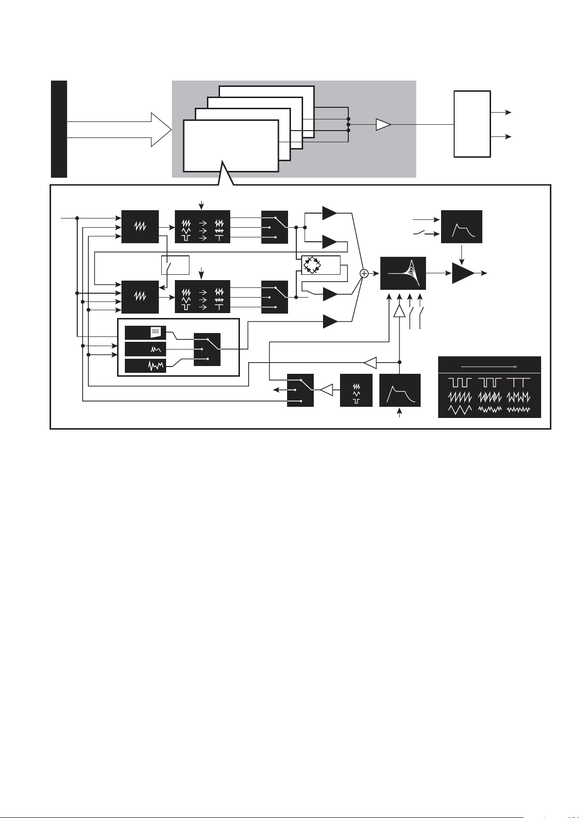
Block diagram
4 VOICE ASSIGNER
VOICE 3
VOICE 4
VOICE 1
VOICE 2
Voice Mixer
DIGITAL
EFFECTS
OUTPUT L
OUTPUT R
VOICE
PITCH
PITCH
PITCH
LFO
EG
LFO
LFO
LFO
VCO 1
EG
FM
VCO 2
EG
USR
VPM
NOISE
WAVE SHAPE
OSC
LFO
SYNC
WAVE SHAPE
MULTI ENGINE
USR
VPM
NOISE
SAW
TRI
SQR
SAW
TRI
SQR
SHAPE LFO
VCO1 level
CROSS MOD
depth
RING
MOD
VCO2 level
MULTI level
int
PITCH EG int
LFO
gate
velocity
VCF
EG Int
EG
gate
keytrack
velocity
AMP EG
VCA
wave shape amount
0% 100%
4
Page 5
Controls and connections
3. VCO 1/VCO 2/MULTI ENGINE section
2. VOICE MODE section
6. AMP EG/EG/LFO section
EDIT/SEQUENCER
11. Buttons 1–16
12. Joy
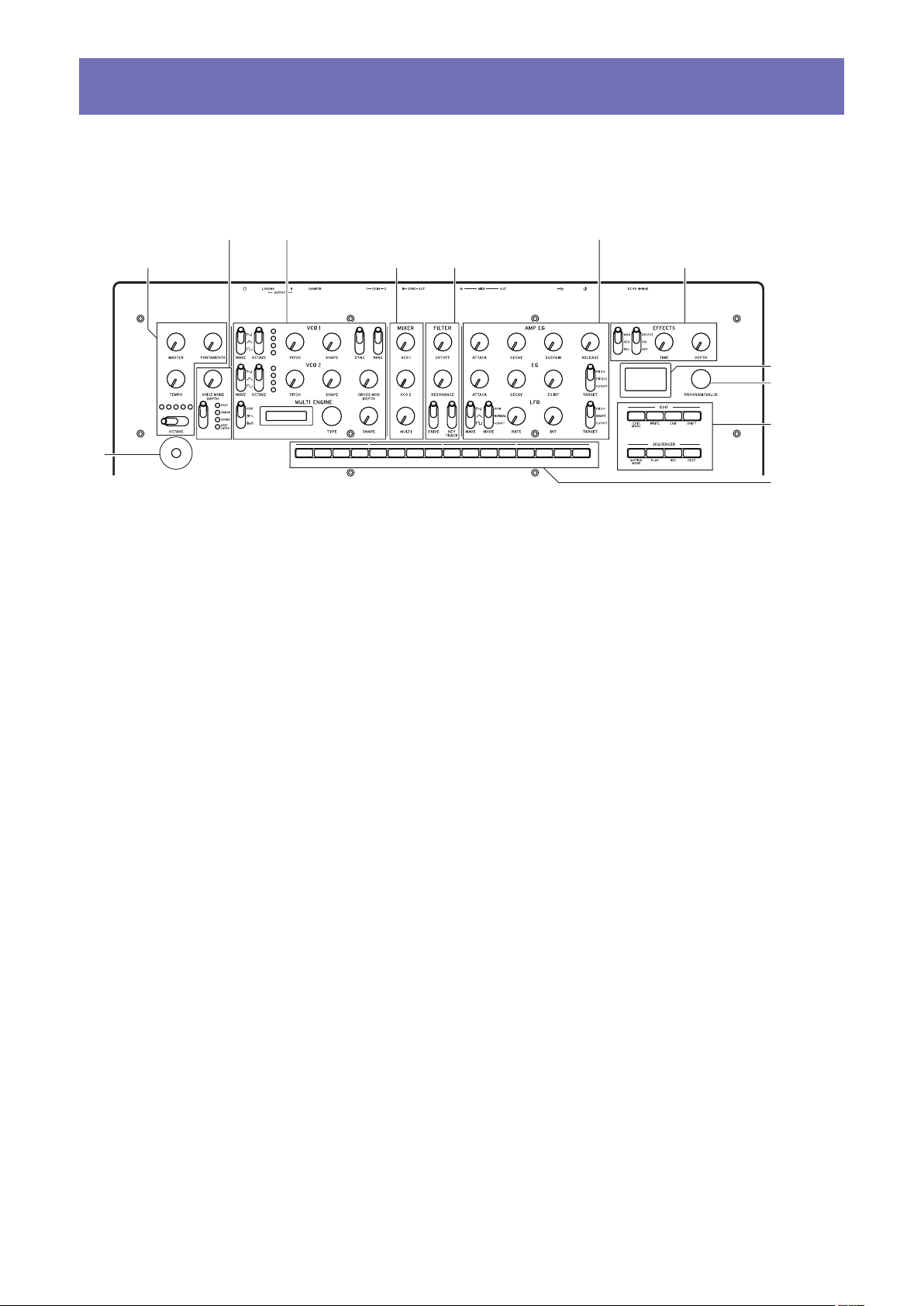
Front panel controls
This diagram shows the layout of the front panel knobs, switches, and buttons.
1. MASTER controls
stick
MASTER controls
MASTER knob
OCTAVE switch (p.9)
TEMPO knob (p.15)
PORTAMENTO knob
(p.15)
1.
VOICE MODE section
(p.15)
VOICE MODE DEPTH knob
VOICE MODE TYPE switch
2.
VCO 1/VCO 2/MULTI ENGINE section
VCO 1 (p.16)
WAVE switch
OCTAVE switch
PITCH knob
SHAPE knob
VCO 2 (p.16)
WAVE switch
OCTAVE switch
PITCH knob
SHAPE knob
SYNC switch
RING switch
CROSS MOD DEPTH knob
MULTI ENGINE (p.17)
NOISE/VPM/USR switch
Display
TYPE knob
SHAPE knob
4. MIXER section 7. EFFECTS section
3.
MIXER section (p.20)
VCO 1 knob
VCO 2 knob
MULTI knob
4.
FILTER section (p.21)
VCF
CUTOFF knob
RESONANCE knob
DRIVE switch
KEYTRACK switch
5.
AMP EG/EG/LFO section
AMP EG (p.22)
ATTACK knob
DECAY knob
SUSTAIN knob
RELEASE knob
EG (p.22)
ATTACK knob
DECAY knob
EG INT knob
TARGET switch
LFO (p.23)
WAVE switch
MODE switch
RATE knob
INT knob
TARGET switch
5. FILTER section
6.
EFFECTS section (p.24)
DEL/REV/MOD switch
OFF/ON/SELECT switch
TIME knob
DEPTH knob
7.
Display (p.9) (p.42)
8.
PROGRAM/VALUE knob
(p.9) (p.30)
9.
EDIT/SEQUENCER section
EDIT
(p.30)
EDIT MODE button
WRITE button
EXIT button
SHIFT button
SEQUENCER
MOTION MODE button
PLAY button
REC button
REST button
10.
Buons 1–16 (p.10)
(p.28) (p.30)
11.
Joystick (p.9)
(p.25)
8. Display
9.
PROGRAM/VALUE
knob
10.
section
5
Page 6
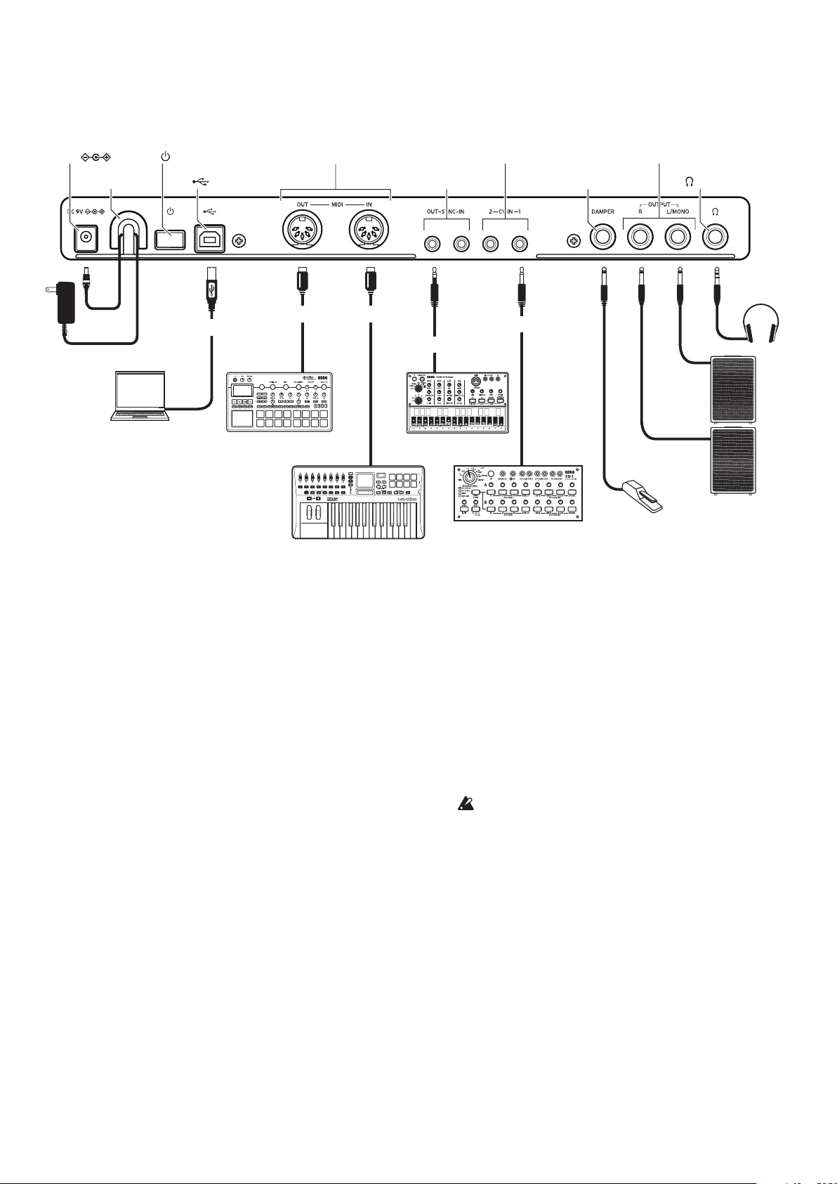
Rear panel connections
The illustration below shows a typical example of connections for the minilogue xd. Connect the
minilogue xd as appropriate for your own sound system.
1. DC 9V jacks
2. Cord hook
AC adapter
(included)
Computer
3. (Power) switch
4. (USB B) Port
USB cable
USB
Sound module, rhythm machine, etc.
5. MIDI IN, OUT connectors
MIDI cable
MIDI IN
MIDI keyboard, rhythm machine, etc.
MIDI cable
Stereo mini-cable
MIDI OUT
7. CV IN 1, 2 jacks
6. SYNC IN, OUT jacks
Monaural mini cable
SYNC IN
Groove machine
Step sequencer,
modular synthesizer, etc.
CV OUT
9. OUTPUT L/MONO, R jacks
8. DAMPER jack
Damper pedal,
pedal switch, etc.
10. (Headphones) jack
Headphones
INPUT
INPUT
Powered monitor speaker
1.
DC 9V jack (p.7)
Connect the DC plug of the included AC
adapter to this jack.
2.
Cable hook (p.7)
Loop the DC plug end of the AC adapter cable
around this hook to prevent the cable from being accidentally pulled out.
3.
Power switch (p.7)
Use this switch to turn the minilogue xd on or
off.
4.
USB B port (p.51)
This port allows the minilogue xd to exchange
MIDI messages with your computer.
5.
MIDI IN, OUT connectors (p.50)
Connect these to an external MIDI device so
that MIDI data can be transmitted and received.
6.
SYNC IN, OUT jacks (p.49)
Connect these jacks to the SYNC IN, OUT jacks
on the Korg volca series, to synchronize with
the pulses and steps that are outputted. The
SYNC OUT jack outputs a 5 V pulse, 15 ms
long at the beginning of each step. Use a stereo
mini cable for this connection.
7.
CV IN 1, 2 jacks (p.50)
Connect these jacks to a device that can output
CV signals to control the parameters of the
minilogue xd. The voltage range is from –5 V
to +5 V. Use a monaural mini cable (or a stereo
mini cable).
8.
DAMPER jack
Connect a Korg DS-1H damper pedal (sold
separately) or a PS-1/PS-3 pedal switch (sold
separately) to control the damper function.
The minilogue xd does not feature a half-
damper function.
9.
OUTPUT L/MONO, R jacks (p.7)
Connect these jacks to a powered monitor
speaker or similar device. Adjust the volume
level using the MASTER knob. To output monaural sound, use the OUTPUT L/MONO jack.
10.
Headphones jack (p.7)
Connect your headphones to this jack. This
jack outputs the same signal as that of the
OUTPUT jack.
6
Page 7

Connecting the AC adapter
Connect the DC plug of the included AC adapter to the DC 9V jack located on the rear panel
1.
of the minilogue xd.
Be sure to use only the included AC adapter. Using any other AC adapter may cause mal-
functions.
Hook the AC adapter cord onto the cord hook.
2.
Do not use excessive force when pulling the cord off the hook. Doing so may damage the
plug.
Connect the plug of the AC adapter to an AC outlet.
3.
Be sure to use an AC outlet of the correct voltage for your AC adapter.
Connecting audio devices
Be sure that all of your devices are turned off when making connections. Making connec-
tions with the power still turned on may damage the device or speaker.
Connect the OUTPUT L/MONO, R jacks on the minilogue xd to your powered monitor
•
speaker, mixer or other audio device.
To output monaural sound, use the OUTPUT L/MONO jack.
To use headphones, connect the plug on your headphones to the headphones jack.
•
Tip: Adjust the volume levels for the OUTPUT jacks and headphones jack using the MASTER
knob.
Turning the power on/off
Turning the minilogue xd on
Make sure that both the minilogue xd and any external output devices such as powered monitor
speakers are turned off, and turn the volume of all devices all the way down.
Hold down the Power switch on the rear panel of the minilogue xd; once the “minilogue xd”
1.
logo appears in the display, take your nger o the Power switch.
The word “Tuning...” will appear on the display, and the instrument will enter Tuning mode
for the analog synthesizer circuit, for around 15 seconds. After this, the minilogue xd will enter
to Play mode.
Turn on any external output devices such as powered monitor speakers.
2.
Adjust the volume of your external output equipment, and adjust the minilogue xd’s volume
3.
using the MASTER knob.
7
Page 8
Turning the minilogue xd off
Any program data in the minilogue xd that has not been saved will be lost when the power is
turned off. Be sure to save any programs and other important data that you have edited (p.14
“Saving a program”).
Lower the volume of your powered monitors or external output system, and turn them o.
1.
Hold down the Power switch on the rear panel of the minilogue xd; to turn o the power
2.
after the display goes blank, take your nger o the power switch.
After turning the minilogue xd off, wait about 10 seconds before turning it on again.
Auto power off feature
The minilogue xd features an auto power off feature that can automatically turn the minilogue xd
off after 4 hours have elapsed with no operation of the knobs, switches, buttons, or keyboard. By
default, the factory setting for auto power off is enabled. The auto power off can be disabled using the steps below.
2, 4
1
123456781110 12913141516
3
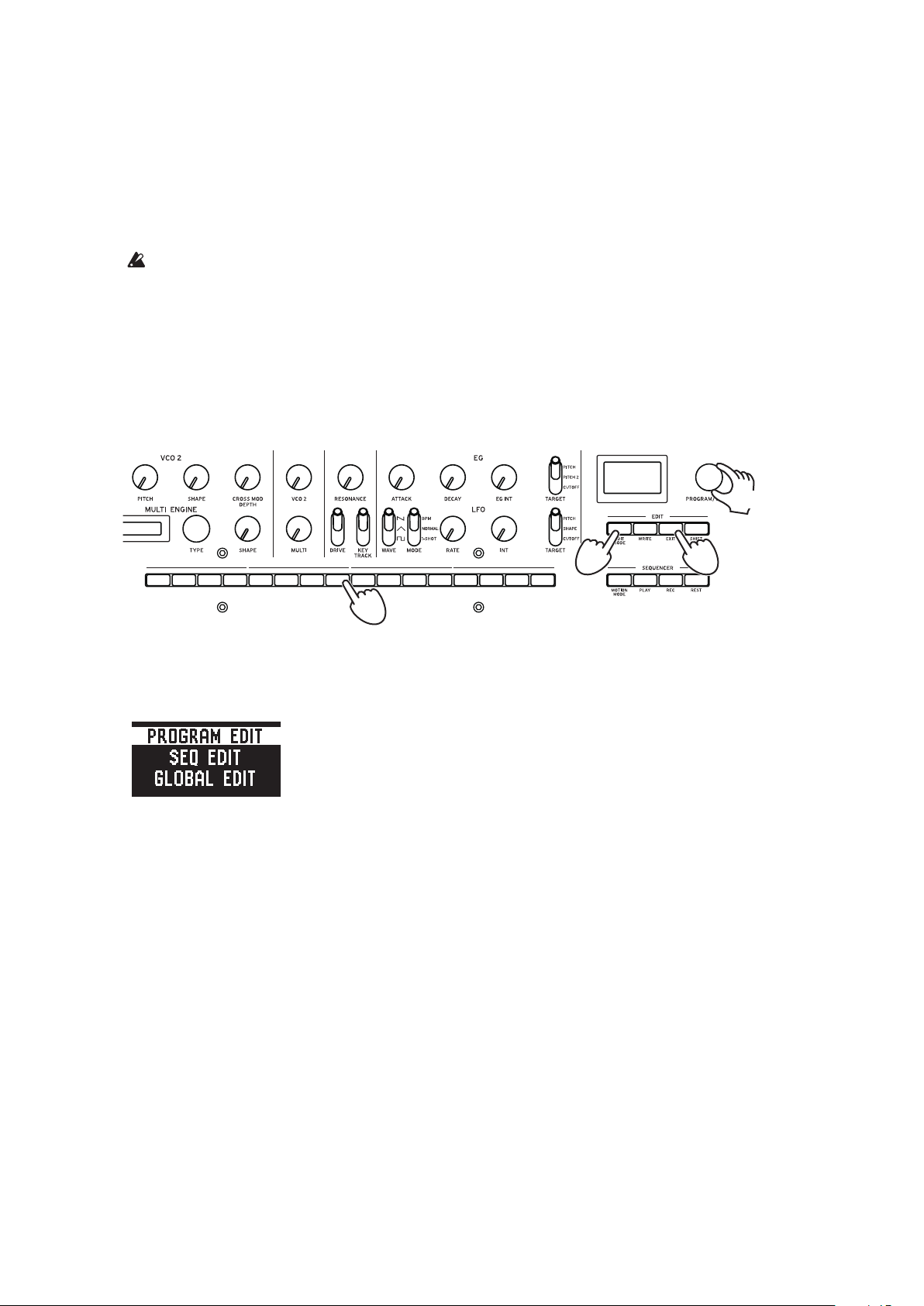
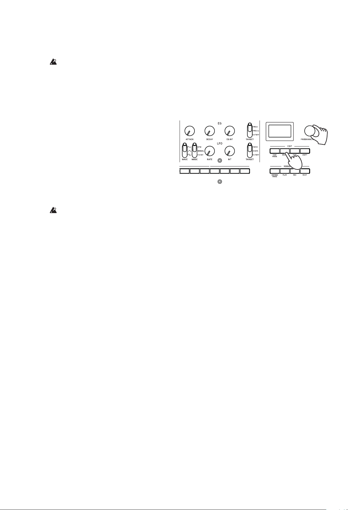
Press the EDIT MODE buon.
1.
The minilogue xd will enter Edit mode, and the display will look like the illustration shown
below.
Turn the PROGRAM/VALUE knob, and select “GLOBAL EDIT.”
2.
The minilogue xd will enter GLOBAL Edit mode.
Tip: GLOBAL EDIT can also be selected by pressing the EDIT MODE button.
Press buon 8 three times.
3.
“Auto Power Off” will be displayed.
Turn the PROGRAM/VALUE knob, and select “O”.
4.
Press the EXIT buon.
5.
The minilogue xd will enter Play mode, and the display will indicate the current program.
5
8
Page 9
Playing the minilogue xd
Selecting and playing a program
The minilogue xd features 500 program memories. When the unit is shipped from the factory,
preset programs are assigned to program numbers 1–200. Programs 201–500 contain init programs
(programs that have been initialized).
2
Make sure this button is unlit.
1
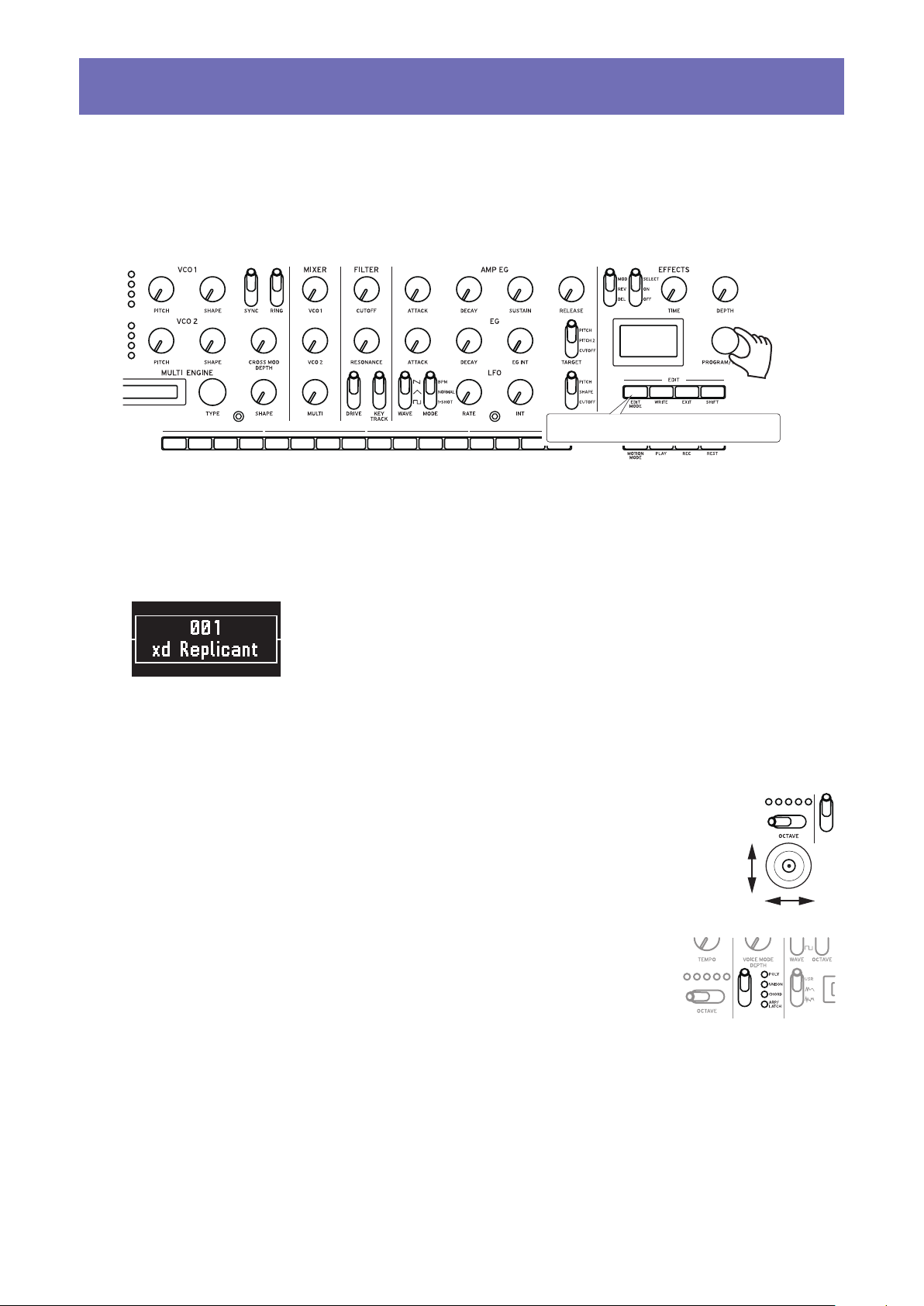
Check that the minilogue xd is in Play mode.
1.
In Play mode, verify that the EDIT MODE button on the front panel is unlit. If the EDIT MODE
button is lit, press the EXIT button.
Turn the PROGRAM/VALUE knob to select a program.
2.
The display will indicate the program name. For details, refer to “Program list” (p.55).
Tip: In addition to showing the program name, the display can also be used as an oscilloscope
to show the waveform created by the electrical signals of the sound.
Play the keyboard and try using the joystick and OCTAVE switch and other controls on the
3.
front panel.
You can use the OCTAVE switch to transpose the playing area of the key-
board by ±2 octaves.
The joystick mainly controls the pitch when moved from left to right, and
changes parameters such as the cutoff frequency and vibrato depth when
moved up and down. You can also change which parameters are controlled
by the joystick. See “Button 4 (JOYSTICK)” (p.32) for details.
Use the VOICE MODE TYPE switch to switch between voice
modes. Select a voice mode and play. To learn more about voice
modes, see “VOICE MODE section” (p.15).
9
Page 10
Using Favorites
You can use the favorites to register up to 16 programs that you like, to easily call them back later.
Recalling your favorite programs
In Play mode, press one of the buons from 1–16 while holding down the SHIFT buon.
1.
The favorite program previously registered to that button will be recalled, and the program
name will be shown in the display.
1
12345678 1110 12913141516
1
Registering your favorite programs
In Play mode, turn the PROGRAM/VALUE knob to select the program you like.
1.
The display will indicate the program name.
12345678 1110 12913141516
Hold down one of the buons from 1–16 while keeping the SHIFT buon pressed.
2.
The program will be registered as a favorite program, and “Registered to Favorite” will be
shown in the display.
Tip: The favorite programs that you register will be saved in the global settings.
1
2
2
10
Page 11
Playing the sequencer
Each program in the minilogue xd includes sequence data. In this section, we’ll play the sequence
data saved as part of the preset programs.
Turn the PROGRAM/VALUE knob to
1.
select a program.
The display will indicate the program
name.
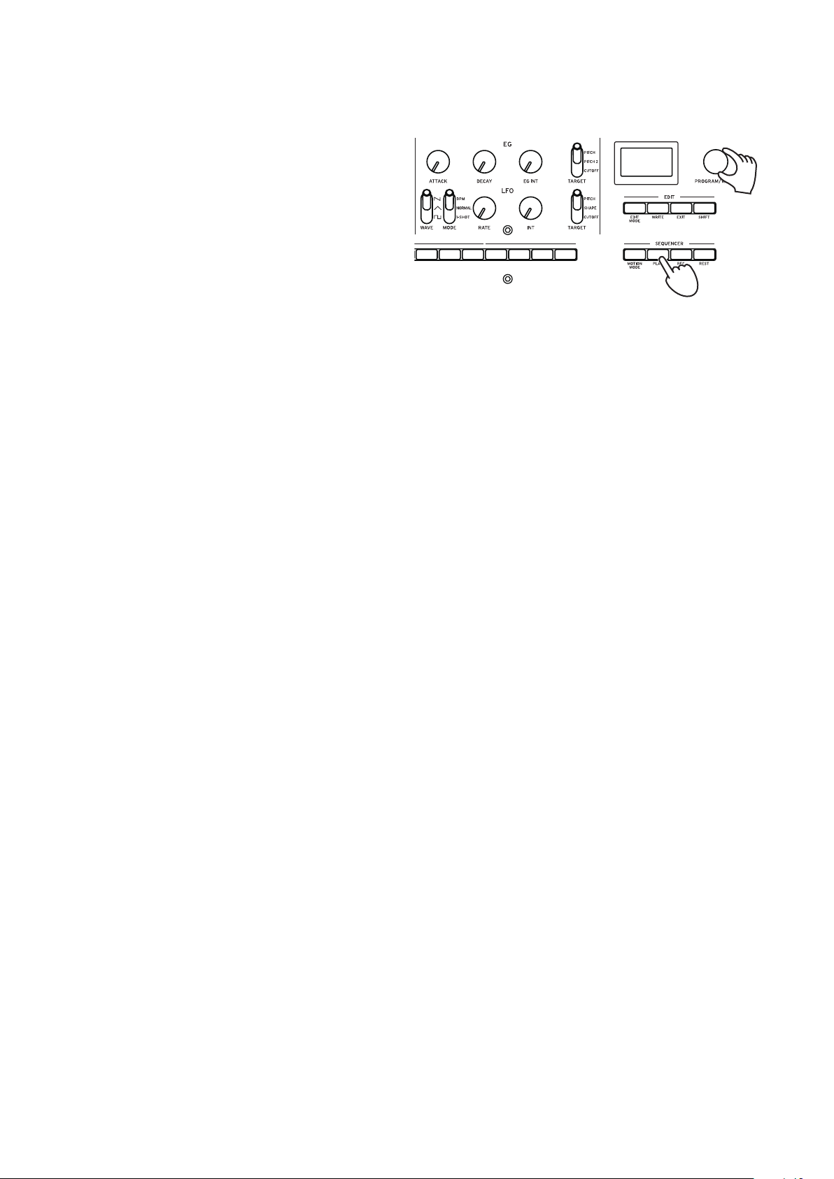
Press the PLAY buon in the SE-
2.
QUENCER section.
The sequence data that is recorded in
the current program will begin playing.
The 1–16 buttons will light up to show
the current step while the sequencer is playing.
Tip: The sequencer tempo is set individually in each program. You can change the tempo in
SEQ EDIT mode, “BPM” (p.37). You can also adjust the tempo from 56.0 to 240.0 BPM
(beats per minute) by turning the TEMPO knob.
Press the PLAY buon once more to end the Sequencer playback.
3.
2, 3
1
11
Page 12

Programs
* Edit mode parameters
Program architecture
A program includes settings for sounds, voice mode and effects, as well as sequence data and so
on. (MASTER knob and joystick settings are not included in programs.)
Try editing each related parameter, and enjoy the sounds of the minilogue xd.
Basic parametres
MASTER
TEMPO
OCTAVE
PORTAMENTO
VOICE MODE DEPTH
VOICE MODE Type
VCO 1
WAVE
OCTAVE
PITCH
SHAPE
VCO 2
WAVEOCTAVE
PITCH
SHAPE
SYNC
RING
CROSS MOD DEPTH
MULTI ENGINE
TYPE
NOISE/VPM/USR
SHAPE
Engine Parm Setting
(SHIFT + SHAPE)
MIXER
VCO1 Level
VCO2 Level
MULTI Level
VCF
CUTOFF
RESONANCE
DRIVE
KEYTRACK
AMP EG
ATTACK
DECAY
SUSTAIN
RELEASE
EG
ATTACK
DECAY
EG INT
TARGET
LFO
WAVE
MODE
RATE
INT
TARGET
MOD
O/On
MOD FX Type
Sub Type (SHIFT + TypeSELECT)
DELAY
O/On
DELAY Sub Type
TIME
DEPTH
Wet/Dry (SHIFT + DEPTH)
REVERB
O/On
REVERB Sub Type
TIME
DEPTH
Wet/Dry (SHIFT + DEPTH)
Sequence data
NOTE [STEP 1–16]
GATE TIME [STEP 1–16]
3 15 16
STEP
NOTE
GATE
1𝅘𝅥𝅮2
𝅘𝅥
14
𝅘𝅥𝅮
𝅘𝅥
Detail parametres *
JOY
X+ Bend Range
X- Bend Range
Y+ Assign
Y+ Range
Y- Assign
Y- Range
CV INPUT
CV IN Mode
CV IN1 Assign
CV IN1 Range
CV IN2 Assign
CV IN2 Range
STICK
PITCH SETTING
Microtuning
Scale Key
Program Tuning
Transpose
LFO
LFO Target Osc
LFO Key Sync
LFO Voice Sync
MODULATION
EG Velocity
Amp Velocity
OTHER SETTINGS
Multi Octave
Multi Routing
EG Legato
Portamento Mode
Portamento BPM
Program Level
MULTI ENGINE
Parameter 1-6
PROGRAM NAME
Program Name
12
Sequence parameters *
BPM (TEMPO)
Step Length
Step Resolution
Swing
Default Gate Time
Motion Type (1–4)
Motion Enable (1–4)
Motion Smooth (1–4)
Page 13

Creating sounds
You can edit the parameters that make up a program, in order to modify the sound as you like.
There are two ways to create sounds on the minilogue xd.
•You can select an existing program that’s close to the sound you want, and edit that program’s
parameters to achieve your own custom sound.
•You can also create your own sound from scratch from an init program.
Editing an existing program
In Program mode, select the program that you want to use as a starting point.
1.
Use the knobs and switches on the front panel.
2.
Take a moment to consider the differences between the current program and the sound you
have in mind, and use the front panel controls to edit the necessary parameters.
Tip: For details on how the pitch, sound, and volume change when using the knobs and
switches, refer to “Basic parameters” (p.15).
We recommend that you save the program on the minilogue xd after editing the sound.
Any edits that you make will be lost if you turn off the power or recall a different program.
See “Saving a program” (p.14) for details.
Creating a program from scratch
To create a program from scratch, we recommend that you use the panel load function. This will
load the current settings of each front panel control and provide a simple starting point for your
sonic creations.
As you explore the front panel controls, you can see how each parameter will affect the sound,
making it easier to understand how each section of the minilogue xd functions and how the parameters interact.
You can also create programs after initializing them (p.37 “Initialize Program”).
Panel load function
When the PLAY button is pressed while holding down the SHIFT button, the panel load function will be enabled. The sound will change to reflect the panel settings, and “Load Panel” will be
indicated in the display.
13
Page 14
Saving a program
We recommend that you save your program on the minilogue xd after editing the sound to your
liking.
Any edits that you make will be lost if you turn off the power or recall a different program
before saving the program.
Edit the program in Play mode.
1.
See “Basic parameters” (p.15) for details.
Press the WRITE buon. The minilogue xd will enter write standby mode, and the WRITE
2.
buon will blink.
The display will indicate the message
“Where to write?”.
Turn the PROGRAM/VALUE knob to
3.
select the program number where your
new sound will be saved.
Tip: Press the EXIT button to cancel the
operation.
Press the WRITE buon once more.
4.
The display will indicate the message “Complete”.
Never turn off the power while programs are being saved. Doing so may destroy the inter-
nal data.
2, 4
3
14
Page 15
Basic parameters
In this section, we’ll explain the basic parameters that make up a program.
The basic parameters are assigned to the knobs and switches on the front panel.
MASTER controls
To learn more about the OCTAVE button, see “Selecting and playing a program” (p.9).
TEMPO knob [BPM 56.0...240.0]
Use this parameter to adjust the tempo of the sequencer for each program in beats per minute
(BPM). When the voice mode is “ARP”, the value set here is also used for the arpeggiator tempo.
PORTAMENTO knob [0...127]
This parameter controls the portamento time.
The further the knob is turned to the right, the longer the portamento time will be.
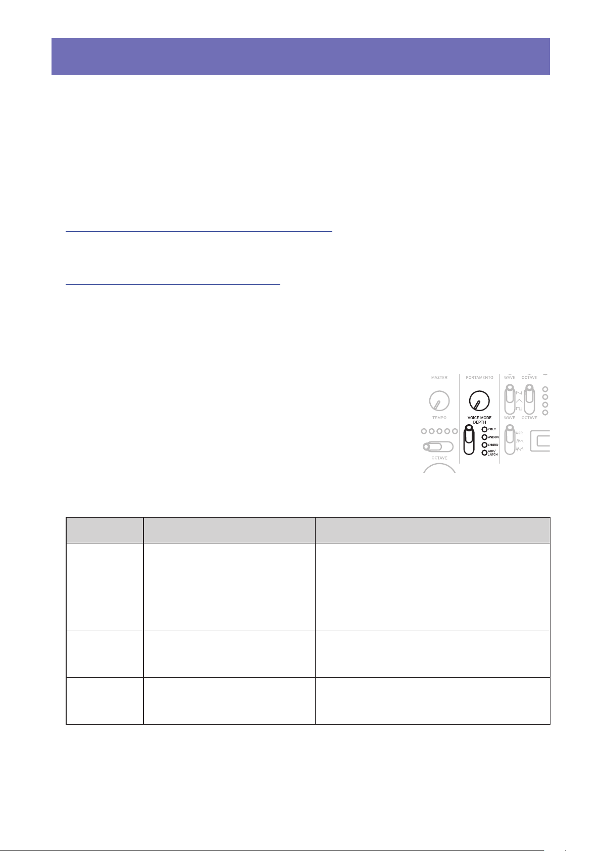
VOICE MODE section
The minilogue xd features four analog synthesizer voices. By changing the Voice mode, you can combine and allocate the voices in
different ways.
There are four voice modes. Use the VOICE MODE TYPE switch to
select a voice mode.
Turning the VOICE MODE DEPTH knob adds different effects for
each Voice mode.
Voice mode list
Type Action VOICE MODE DEPTH knob eect
POLY Used for basic playing as a
4-voice polyphonic synth.
UNISON The 4 voices will be stacked
together into a single voice in
unison, as a mono synth.
[POLY, DUO 0...1023]
Turn the knob to the right to switch to DUO
mode, which stacks two voices when playing a key. Turning the knob to the right will
increase the sound of the stacked voice, and
deepen the detune effect.
[Detune 0C...50C]
Turning the knob to the right will increase the
detuning effect.
CHORD The voices will play as a chord.
[Mono, 5th, sus2, m, Maj, sus4, m7, 7, 7sus4,
Maj7, aug, dim, m7
Selects either mono or the chord type.
♭
5, mMaj7, Maj7♭5]
15
Page 16
Type Action VOICE MODE DEPTH knob eect
0 1023
ARP/LATCH Uses the arpeggiator to play up
to 4 voices.
Switches between LATCH ON
and OFF.
Set the arpeggiator tempo, swing
and gate time using the “TEMPO
knob” (p.15), “Swing” (p.37)
and “Default Gate Time”
(p.37) settings.
[MANUAL 1, MANUAL 2, RISE 1, RISE 2, FALL 1,
FALL 2, RISE FALL 1, RISE FALL 2, POLY 1, POLY 2,
RANDOM 1, RANDOM 2, RANDOM 3]
Selects the arpeggiator type.
If you set the VOICE MODE TYPE switch
to ARP/LATCH and then move the switch
down, the latch will be turned on (the LED
will blink), and the arpeggiator will keep
playing even after you take your hands off
the keyboard. If you move the switch up
while latched, the switch will latch off (the
LED will light).
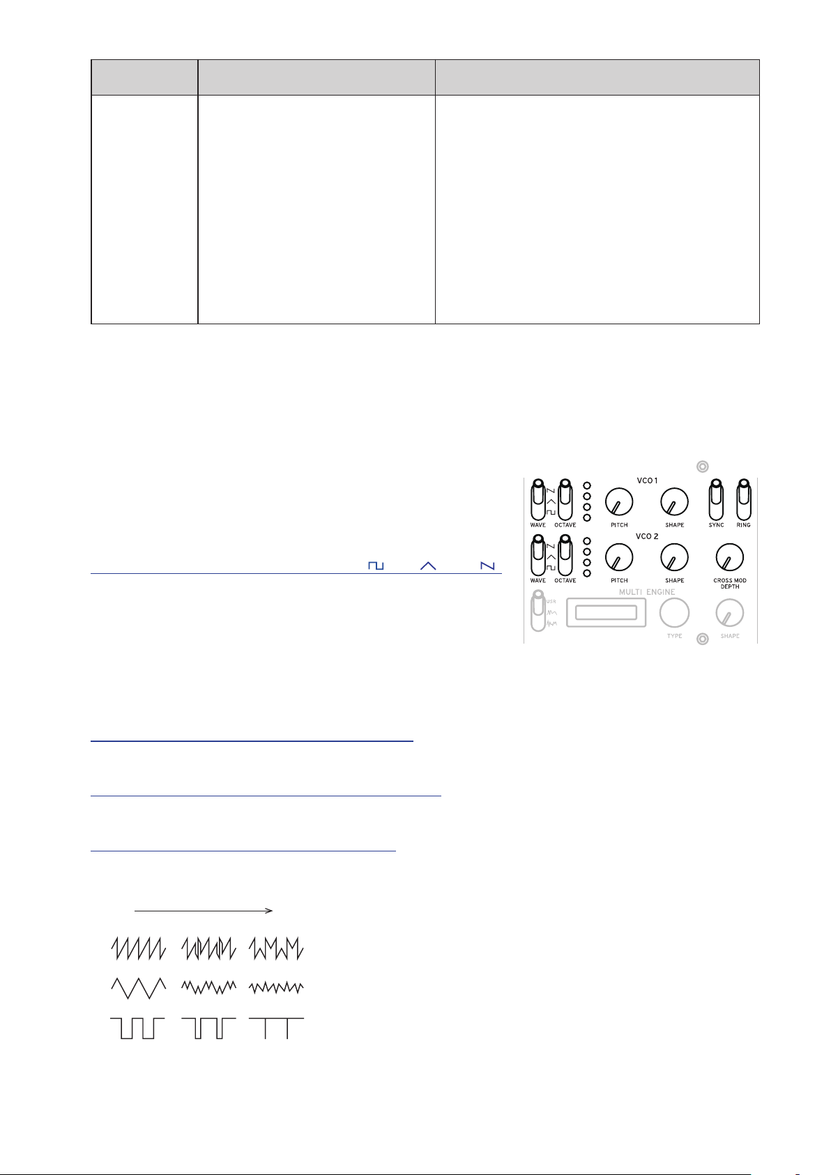
VCO 1/VCO 2/MULTI ENGINE section
VCO 1, VCO 2
There are two oscillators in the minilogue xd. Here, we will
adjust the basic settings for the sound, including pitch (OCTAVE, PITCH), waveform (WAVE, SHAPE) and so on.
VCO: Voltage Controlled Oscillator
WAVE switch [SQR , TRI , SAW ]
This sets the waveforms for oscillators 1 and 2.
SQR (square wave): This waveform is used for electronic
and wind instrument sounds.
TRI (triangle wave): This waveform has a rounder feel than
the sawtooth or square wave.
SAW (sawtooth wave): This waveform is used to create sounds typical of analog synthesizers,
such as synth basses and synth brass.
OCTAVE switch [16’, 8’, 4’, 2’]
The pitch of oscillators 1 and 2 can be set in octave steps.
PITCH knob [–1200...+1200]
The pitch, or tuning, of oscillators 1 and 2 can be set in one-cent steps.
SHAPE knob [0...1023]
This knob will determine the final shape, complexity, or duty-cycle (square) of the selected waveform for oscillators 1 and 2.
16
Page 17
SYNC switch [OFF/ON]
This switch lets you sync the oscillators.
Oscillator sync is a popular effect for creating edgy synth leads.
ON (up position): With this type of modulation, the phase of oscillator 2 is forcibly synchronized
to the phase of oscillator 1. This adds harmonic overtones to the frequency of oscillator 2, making
a complex waveform.
VCO 1 Wave
Sync
VCO 2 Wave (original)
VCO 2 Wave (output)
RING switch [OFF/ON]
This lets you achieve a ring modulation effect.
Adjust the pitch of oscillator 2 to create non-tonal and metallic sounds.
ON (up position): Oscillator 1 is used to ring modulate oscillator 2.
VCO 1
VCO 2
RING MOD
CROSS MOD DEPTH knob [0...1023]
Cross Mod (Modulation) allows oscillator 1 to modulate the pitch of oscillator 2.
Turning the knob to the right results in stronger modulation.
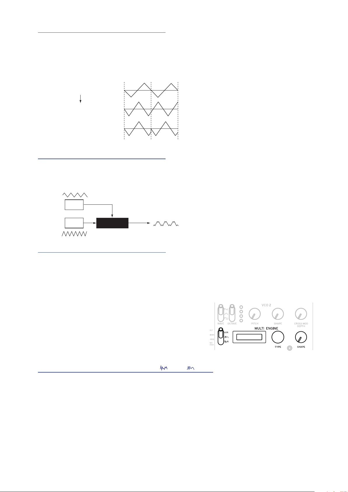
MULTI ENGINE
The MULTI ENGINE is a digital sound generation engine.
This engine operates as a noise generator, a VPM oscillator or a user oscillator, to make a wide range of
sounds not possible with analog oscillators. You can
load your own oscillator programs into the user oscillator to make sounds.
NOISE/VPM/USR switch [NOISE , VPM , USR]
This sets which engine will be used, the noise generator, VPM oscillator or user oscillator.
NOISE: The MULTI ENGINE is used as a noise generator.
VPM: The MULTI ENGINE is used as a VPM oscillator.
USR: The MULTI ENGINE is used as a user oscillator.
The TYPE knob and SHAPE knob work differently, depending on the NOISE/VPM/USER switch
setting. The settings are explained below.
17
Page 18
NOISE
Noise is used to create percussion instrument sounds, or sound effects such as surf.
Select one of the four noise generators using the TYPE knob.
Move the SHAPE knob to make changes in the sound.
TYPE knob [High/Low/Peak/Decim]
Select the noise generator to use.
The noise generator name will be indicated on the MULTI ENGINE display.
High: A high-pass filter will be used.
Low: A low-pass filter will be used.
Peak: A peak filter (bandpass filter) will be used.
Decim: A decimator will be used.
SHAPE knob
Set the noise generator parameter to make changes to the sound.
The parameters differ depending on the noise generator that you select using the TYPE knob, with
the following effects.
SHAPE knob effects
Type Parameter Eect
High CUTOFF
(SHAPE knob)
Low CUTOFF
(SHAPE knob)
Peak BANDWIDTH
(SHAPE knob)
Decim RATE
(SHAPE knob)
KEY TRACK
(SHIFT button+SHAPE knob)
[10.0Hz...21.0kHz]
Adjusts the cutoff frequency of the HPF.
[10.0Hz...21.0kHz]
Adjusts the cutoff frequency of the LPF.
[110.0Hz...880.0Hz]
Adjusts the peak characteristic bandwidth.
[240Hz...48.0kHz]
Adjusts the sample rate.
[0.0%...100.0%]
Adjusts the depth of the sample rate via keyboard
tracking.
18
Page 19

VPM
f
output
mod attack
This engine is a VPM (Variable Phase Modulation) oscillator. The engine features a simple structure with one carrier and one modulator, but allows you to create a wide range of sounds.
Sixteen oscillator types are available for this VPM oscillator.
mod decay
shape mod int.
pitch ratio
pitch
eg
mod. depth (index)
phasephase
mod
eedback
carrier
noise depth
drive
noise
TYPE knob [Sin1...Throat]
This selects the oscillator type to use.
The name of the oscillator type will be indicated on the MULTI ENGINE display.
Tip: For the last four types after Decay1, setting Shape Mod Int to “–100%” will disable com-
pletely the effect of the EG.
Sin1: A basic oscillator type, using a sine wave for both the carrier and modulator.
Sin2: Sine wave carrier and a modulator with self-feedback.
Sin3: Sine wave carrier with a 3x harmonics modulator.
Sin4: Sine wave carrier with 5x harmonics modulator.
Saw1: Modulated sawtooth carrier basic type.
Saw2: Carrier using a sine wave to simulate a sawtooth.
Squ1: Square wave carrier type.
Squ2: Carrier using a sine wave to simulate a square wave.
Fat1: 1/4 subharmonic modulator with self-feedback and driven carrier output, emphasizing the
lower harmonics.
3/4 subharmonic modulator with self-feedback and driven carrier output, emphasizing the
Fat2:
lower harmonics.
Air1: Noise-modulated sine wave carrier.
Air2: Sine wave carrier modulated by both noise and a sine wave.
Decay1: Type with decaying modulation amount.
Tip: You can edit the relative offsets of the internal EG decay time of the VPM (see block dia-
gram) by using the parameters in PROGRAM EDIT mode “Button 10 (MULTI ENGINE)”
(p.36).
Decay2: Type with strong decaying modulation amount.
Creep, Throat: Experimental, somewhat atonal type with complex and evolving modulations.
19
Page 20

SHAPE knob
Turning the SHAPE knob only will set the “MOD DEPTH,” and turning the SHAPE knob while
holding down the SHIFT button will set the “RATIO OFFSET.”
These parameters are common for all oscillator types, and produce the following effects.
SHAPE knob effects
Type Parameter Eect
Common MOD DEPTH
(SHAPE knob)
RATIO OFFSET
(SHIFT button+SHAPE knob)
Tip: Besides the SHAPE knob, the oscillator settings can be changed in detail with six param-
eters in PROGRAM EDIT mode. See “When the VPM oscillator is selected” (p.36) for
details.
[0.00:15.00...] (range changes depending on TYPE)
This adjust the index and sets the intensity of the
modulator.
[1:4, 1:2, 1:1, 2:1...] (range changes depending on
TYPE)
This adjusts the modulator ratio and adds overtones.
USR
You can load your own oscillator programs into a user oscillator to make sounds on the minilogue
xd.
Up to 16 user oscillators can be saved. One factory-set default user oscillator is included with the
minilogue xd for demo purposes.
See the “logue SDK” (www.korg.com) for details.
TYPE knob
Selects a user oscillator.
The name of the user oscillator will be indicated on the MULTI ENGINE display.
SHAPE knob [0.0%... 100.0%]
Produces the effect that is set for the user oscillator.
MIXER section
Use this section to set the output levels of oscillator 1, 2 and the
MULTI ENGINE, and to adjust the balance.
VCO 1 knob [0...1023]
VCO 2 knob [0...1023]
MULTI knob [0...1023]
These knobs control the output levels.
20
Page 21

FILTER section
Low resonance value
VCF
The low-pass filter creates a brighter or darker sound by selectively
filtering certain parts of the harmonic spectrum of the sound generated
by the oscillators and the noise generator.
VCF: Voltage Controlled Filter
CUTOFF knob [0...1023]
This knob is used to set the cutoff frequency (the frequency at which
the filter is applied).
Turning the knob to the left will lower the cutoff frequency, and turning the knob to the right will raise the cutoff frequency.
If the CUTOFF value is set too low, the volume may be extremely
low.
RESONANCE knob [0...1023]
Also known as Peak or Q, the RESONANCE control adds additional emphasis to the overtones
occurring at the CUTOFF frequency, giving a distinctive character to the sound.
Turning the knob to the right will emphasize the harmonic content, increasing the resonance effect.
High resonance value
Tip: The overtones that are emphasized will change depending on the cutoff frequency. For
this reason, it’s good to adjust the CUTOFF knob while adjusting the RESONANCE knob.
When emphasizing the overtones in this way, the sound may distort depending on the
cutoff frequency or the input audio.
DRIVE switch [0%, 50%, 100%]
Sets the distortion effect produced by the drive circuit, in three stages.
0% (switch in the lower position): no drive effect.
50% (switch in the center position): drive effect will be set at half strength.
100% (switch in the upper position): drive effect will be set at maximum.
KEYTRACK switch [0%, 50%, 100%]
Key tracking allows the note played on the keyboard to influence the cutoff frequency of the filter.
0% (lower position): No keyboard tracking will be applied.
50% (center position): Keyboard tracking will affect the cutoff frequency, but at only half the
amount produced by 100%. For example, playing the C5 note on the keyboard will produce a harmonic that is an augmented fourth higher than the cutoff frequency of C4.
100%
(upper position): The cutoff frequency will change at the same rate/slope as the pitch of the
keyboard, centered on C4.
higher than the C4 key.
For example, pressing the C5 key will give a cutoff frequency one octave
21
Page 22

EG/LFO section
Attack Level
Time
Level
Time
Time
Time
AMP EG
These are the settings for the envelope generator (EG), which
controls changes in the signal volume of the VCA over time.
0
VCA: Voltage Controlled Amplifier / EG: Envelope Generator
Note on Note o
Sustain
Level
Attack
Decay
Release
ATTACK knob [0...1023]
The ATTACK specifies the time required for the EG to reach its maximum level once a new note is
played (note-on).
DECAY knob [0...1023]
The DECAY specifies the time required for the EG to fall to the preset sustain level once the attack
portion of the EG is complete.
SUSTAIN knob [0...1023]
The SUSTAIN specifies the level that will be maintained after the decay time while the key is held
down.
RELEASE knob [0...1023]
The RELEASE specifies the time required for the EG to reach its minimum level (zero) once the
key or trigger is released (note off).
EG
The envelope generator (EG) is used to change the pitch and cutoff frequency over time.
EG: Envelope Generator
ATTACK knob [0...1023]
The ATTACK specifies the time required for the EG to reach its maximum level once a new note is
played.
DECAY knob [0...1023]
The DECAY specifies the time required for the EG to fall to the preset sustain level once the attack
portion of the EG is complete.
EG INT knob [–100%... 0%...+100%]
Adjusts the intensity of the EG.
Turning the knob to the right will increase the intensity.
When set to a negative value, the EG will be applied in the negative direction.
TARGET switch [PITCH, PITCH 2, CUTOFF]
This sets what the EG will be applied to.
PITCH: Applies the EG to the pitch of VCO 1, VCO 2 and the MULTI ENGINE.
PITCH 2: Applies the EG to the pitch of VCO 2.
CUTOFF: Applies the EG to the cutoff frequency of the FILTER.
22
Page 23

LFO
The LFO is a low frequency oscillator that creates a repeating cyclical signal to modulate the pitch,
sound and so on.
Depending on its target, the LFO can provide vibrato (PITCH); tonal changes to the Oscillators
(SHAPE); or wah-wah (CUTOFF) effects.
LFO: Low Frequency Oscillator
WAVE switch [SQR , TRI , SAW ]
The LFO can be set to a square wave ( ), a triangle wave ( ), or a sawtooth wave ( ).
MODE switch [1-SHOT, NORMAL, BPM]
Specifies the range of change and action for the LFO frequency.
1-SHOT: The LFO stops after a half-cycle from the time that the sound is played. The range of
change for the LFO frequency will be from 0.05 Hz–28 Hz.
NORMAL: The range of change for the LFO frequency will be from 0.05 Hz–28 Hz.
BPM: This synchronizes the LFO frequency to the sequencer’s BPM (beats per minute) set in each
program.
RATE knob [0...1023 / 4, 2, 1, 0, 3/4...1/64]
The RATE knob adjusts the frequency of the LFO.
Turning the knob to the right will increase the LFO frequency.
INT knob [0...511]
The INT knob adjusts the intensity of the LFO.
Turning the knob to the right will increase the LFO intensity.
Tip:
When turning the INT knob while holding down the SHIFT button, the LFO waveform will
be inverted. The setting range is 0– –511.
TARGET switch [CUTOFF, SHAPE, PITCH]
Selects the parameter where the LFO modulation will be applied.
CUTOFF: Modulation is applied according to the VCF CUTOFF knob setting.
SHAPE: Modulation is applied according to the SHAPE knob setting for the oscillator, which is
set in “LFO Target OSC” (p.34) of PROGRAM EDIT mode.
PITCH: Modulation is applied according to the PITCH knob setting for the oscillator, which is set
in “LFO Target OSC” (p.34) of PROGRAM EDIT mode.
23
Page 24

EFFECTS section
The minilogue xd features high-definition digital effects.
You can select one variation from each effect including delay, reverb and modulation, and combine them.
Use the DEL/REV/MOD switch to select the effect type to set.
Next, use the OFF/ON/SELECT switch and the TIME and DEPTH
knobs to set how the effect will be applied.
The effect on/off state and the values of the TIME and DEPTH
knobs are saved along with each effect, so the sound that you set
will remain in memory, even if you use the DEL/REV/MOD switch
to switch the effect.
DEL/REV/MOD switch [DEL, REV, MOD]
Selects the effect type.
DEL: Selects the delay effect.
REV: Selects the reverb effect.
MOD: Selects the modulation effect.
OFF/ON/SELECT switch [OFF, ON, SELECT]
This sets the effect that you have selected using the DEL/REV/MOD switch.
OFF: Turns the effect off.
ON: Turns the effect on.
SELECT: When either “DEL” or “REV” is selected using the DEL/REV/MOD switch, flip the
switch to SELECT to switch between the sub-types for each effect.
When “MOD” is selected using the DEL/REV/MOD switch, flip the switch to SELECT to switch between the effect types (CHORUS ENSEMBLE PHASER FLANGER USER CHORUS ...).
When switching between sub-types, flip the switch to SELECT while holding the SHIFT button
down.
Tip: USER (user effects) are not installed as factory-set default effects, so they cannot be select-
ed, but you can load them into the minilogue xd to make them selectable. See the “logue
SDK” (www.korg.com) for details.
Note: Both delay and reverb user effects cannot be used at the same time. The effect last se-
lected will be enabled.
For details on the effect types and sub-types, refer to “Effects list” (p.53).
TIME knob
This knob specifies the delay time, reverb time or modulation time. The setting range differs depending on the effect type you select.
Turning the knob to the right will increase the speed or lengthen the time.
DEPTH knob [0.0%... 100%]
This sets the depth of the effect.
Turning the knob to the right will increase the intensity.
Tip: When either “DEL” or “REV” is selected using the DEL/REV/MOD switch, turn the
DEPTH knob while holding down the SHIFT button to adjust the wet/dry balance of each
effect. The setting range is MIX WET: 0% – BALANCED – MIX DRY: 0%.
24
Page 25

Sequencer
In this section, we’ll explore recording with the sequencer, one of the elements that makes up a
program. This includes real-time recording, step recording and motion sequence recording, as
well as how to edit the recorded sequences (step edit).
We recommend that you save the sequences you have recorded on the minilogue xd.
The sequence data that you record will be lost if you turn off the power or recall a different
program before saving.
Step recording
Press the REC buon in the SEQUENCER section while the sequencer is stopped.
1.
“STEP REC” and “STEP 1” will be indicated in the display.
If the sequence has already been recorded, the note names will be indicated in the display.
Tip: Select the step you wish to edit. For instance, press button 3 to select step 3.
Use the keyboard, REST buon and other controls to edit the notes.
2.
When you record a note, rest, or tie in step mode, the display will automatically move to the
next step.
Recording notes
The note name for the keys you press on the keyboard will be indicated in the display. Check
the note name in the display, and if it is correct, release your finger to record that note and to
move to the next step.
The note that you played just before releasing your fingers from the keys will be recorded. If
you play a wrong note, do not release the key; instead, keep your finger on the wrong note
while playing the right note. Check the note indicated in the display, and take your finger off
the keyboard to move to the next step.
The “Default Gate Time” (p.37) value from SEQ EDIT mode will be used for the note length
during recording. If you turn the PROGRAM/VALUE knob while playing the keyboard, the
gate time for only the note(s) you played will be changed when recording. If you turn the
PROGRAM/VALUE knob while playing buttons 1–16, the gate time for only the step(s) you
played will be changed.
Recording a rest
You can record a rest by pressing the REST button.
Recording a tie
Press the REST button while holding down a key. The note will be tied to the next note and
recorded.
When the set number of steps have nished recording, step recording will automatically end.
3.
The number of steps is set for each program. You can change the number of steps using the
“Step Length” (p.37) function in the SEQ EDIT mode. Turn the PROGRAM/VALUE knob to
change the step length during step recording.
Tip: Pressing the REC button at any step during recording will stop the step recording at that
step.
25
Page 26

Real-Time recording
This feature allows you to record your keyboard performance on the minilogue xd and add overdubs (recording while adding performance data) in real time.
Press the PLAY buon in the SE-
1.
QUENCER section while the sequencer is stopped.
If a recording already exists, the sequence data will begin playing.
Press the REC buon.
2.
Real-time recording will begin, and
the REC button will light.
Play the keyboard.
3.
The note(s) you play will be recorded.
Press the REC buon once more to stop the recording.
4.
The REC button will go dark.
Press the REC button once more to start recording again.
Tip: When you hold down the REST button during real-time recording, the existing notes in
the sequence will be deleted.
1, 5
2, 4
Press the PLAY buon to nish real-time recording.
5.
The PLAY button will go dark.
Recording a motion sequence
Motion sequencing allows you to record the flipping of switches and the turning of knobs as part
of the sequence, and recreate those motions automatically during playback.
Up to four motion sequences can be recorded, which includes changes to the knobs and switches.
Note: The knobs, switches for which you cannot record motions are as follows.
MASTER knob, TEMPO knob, OCTAVE switch (MASTER), MULTI ENGINE TYPE-USR,
DRIVE switch (FILTER), DEL/REV/MOD switch, SELECT setting of the OFF/ON/SELECT
switch.
Press the PLAY buon to play the sequencer, and then press the MOTION MODE buon.
1.
“MOTION VIEW” will appear in the display, and the motion sequence saved to the program
will show up as a visual graphic.
Press the REC buon.
2.
Real-time recording will begin.
Move the knobs and switches on the minilogue xd.
3.
You can record up to four motion sequences for the knobs and switches.
Note: If you exceed this limit, the message “Motion Full” will be shown in the display, and the
display will enter MOTION CLEAR in the SEQ EDIT mode. See steps 2 and afterwards in
“Deleting a motion sequence” (p.27) for details.
Note: For motion sequences of knobs and switches you moved that are already recorded, the
data previously recorded will be overwritten.
26
Page 27

After the set number of steps have nished recording, the Motion Sequence will automati-
4.
cally nish recording as well.
Follow steps 2 and on to record motion sequences for other knobs and switches. The number
of steps is set for each program. You can change the number of steps using the “Step Length”
(p.37) function in the SEQ EDIT mode.
Deleting a motion sequence
You can delete one of the previously recorded motion sequences from “MOTION CLEAR (1...4)”
(p.38) in SEQ EDIT mode.
Tip: To delete all motion sequences at once, use “Motion Clear” (p.38) in SEQ CLEAR, SEQ
EDIT mode.
4
1
1 2 3 4 5 6 7 8 1110 129 13 14 15 16
2, 3
Press the EDIT MODE buon a number of times to select SEQ EDIT mode.
1.
Press buon 10 to enter MOTION CLEAR.
2.
Tip: While the SHIFT button is pressed, the MOTION VIEW screen will be displayed, where
you can see the graphics for the motion sequences you have recorded.
Press buon 10 a number of times to select the motion sequence to delete.
3.
5
Turn the PROGRAM/VALUE knob to select “CLEAR...?”, and press the WRITE buon.
4.
The selected motion sequence will be deleted.
Press the EXIT buon.
5.
27
Page 28

Editing sequence data (step edit)
Using Step Edit, you can edit the notes and motion sequences that you previously recorded into
sequence data.
1
1 2 3 4 5 6 7 8 1110 129 13 14 15 16
2
Select a program that includes the sequence data you wish to edit.
1.
The MOTION MODE button and buttons 1–16 will light and go dark to show the status for
each step.
Buons 1–16
Buon goes dark Buon lights
MOTION MODE buon
Buon goes dark
Buon lights
Edit the notes and motion sequences for the steps, using the MOTION MODE buon and
2.
buons 1–16.
Play the note.
Doing so will make the MOTION MODE button go dark.
•Hold down one of buttons 1–16 and play a note on the keyboard to record a note at that step.
•Holding down multiple buttons and playing a note on the keyboard will record the same note
at all of the selected steps.
•Holding down multiple buttons next to each other and playing a note on the keyboard will
connect the notes inputted in these steps with a tie.
•If you turn the PROGRAM/VALUE knob while playing buttons 1–16, the gate time for only the
step(s) you played will be changed. See “Default Gate Time” (p.37) for details on setting the
gate time.
Disabled, or no note data available
Disabled, or no motion sequence data
Enabled (note data is recorded)
Enabled (motion sequence data
is recorded)
2
Input a motion sequence.
Doing so will make the MOTION MODE button light up.
Tip: When the MOTION MODE button is lit, the recorded motion sequence will show up as
graphics in the display.
•Hold down one of buttons 1–16 and move a knob or switch to record a motion sequence at that
step.
•Holding down multiple buttons and moving a knob will record the motion sequence at all of
the selected steps.
For example, if you hold down buttons 3 and 5 and turn the LFO INT knob to “50%,” the LFO
INT 50% value will be recorded for steps 3 and 5 respectively. When recording a motion sequence in real time, you can only record continuous changes in value. However, if you use the
step recording feature to record changes as a motion sequence, the changes recorded as a motion sequence will be recorded per step.
28
Page 29

Enable or disable the steps.
•Press buttons 1–16 to enable (the button will light) or disable (the button will go dark) the
steps.
Note: If a note or motion sequence is not recorded for a step, you cannot enable that step.
After you nish step editing, press the PLAY buon to check your sequence data.
3.
The PLAY button will light.
Other editing functions
Use the SEQ EDIT mode when setting the step length, step resolution and other parameters during sequence step recording, as well as for deleting sequence data, or for editing or deleting motions. See “SEQ EDIT mode” (p.37) for details.
29
Page 30

Edit mode
Although nearly all of the minilogue xd’s main parameters can be edited using the knobs and
switches on the panel, the other detailed parameters are accessed using the Edit mode.
There are three sub-modes within the Edit mode: PROGRAM EDIT mode, SEQ EDIT mode, and
GLOBAL EDIT mode.
How to enter the Edit mode
2
1
123456781110 12913141516
3
Press the EDIT MODE buon.
1.
Each Edit mode is shown in the display, and the buttons light.
Press the EDIT MODE buon a number of times or use the PROGRAM/VALUE knob to se-
2.
lect PROGRAM EDIT mode, SEQ EDIT mode, or GLOBAL EDIT mode.
PROGRAM EDIT mode: This mode is used for program editing functions, such as to change
the program name and assign a parameter to the joystick or CV INPUT jack, as well as to select
a microtuning and so on.
SEQ EDIT mode: This mode is used to set the BPM and configure other step sequencer settings, as well as to delete sequence data and so on.
GLOBAL EDIT mode: Use this mode to set how the knobs and switches should function, as
well as settings such as MIDI for the entire synthesizer.
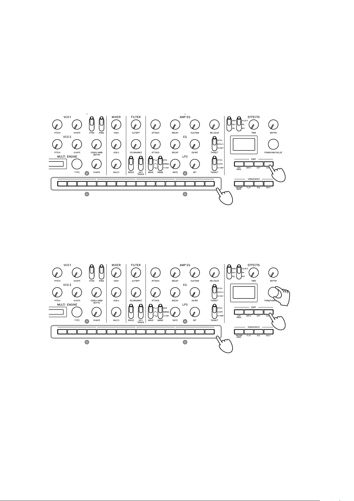
Press one of the lit buons from 1 to 16.
3.
The minilogue xd will enter the selected edit mode, and the parameter names will be indicated
in the display.
•You can go to the page at right by pressing the same button.
Press the same button while holding the SHIFT button down to show the page to the left.
•Turn the PROGRAM/VALUE knob to set the parameters.
For more on the parameters, see “PROGRAM EDIT mode” (p.32), “SEQ EDIT mode”
(p.37) and “GLOBAL EDIT mode” (p.39).
4
Press the WRITE buon to save your parameters after you have congured the parameters in
4.
PROGRAM EDIT mode and SEQ EDIT mode.
Tip: Settings in GLOBAL EDIT are saved automatically when going to a different page.
If you select another program after you have configured the parameters in the PROGRAM
EDIT mode and the SEQ EDIT mode without saving your changes, your settings will be
lost.
30
Page 31

Edit mode parameter list
Button
PROGRAM EDIT mode
SEQ EDIT mode
1 2 3 4 5 6 7 8 9 10 11 12 13 14 15 16
JOYSTICK
(p.32)
X+ Bend
Range
X– Bend
Range
Y+ Assign CV IN1
Y+ Range CV IN2
Y– Assign CV IN2
Y– Range Program
CV INPUT
(p.33)
PITCH
SETTING
(p.33)
CV IN Mode
CV IN1
Assign
Range
Assign
Range
Microtuning
Scale Key LFO Key
Program
Tun ing
Transp ose Portamento
BPM
(p.37)
BPM Step
PARAMETER
Length
Step
Resolution
Swing
SEQ
(p.37)
LFO
(p.34)
LFO Target
OSC
Sync
LFO Voice
Sync
SEQ CLEAR
(p.38)
MODULATION
(p.35)
OTHER
SETTINGS
(p.35)
EG Velocity Multi
Amp
Velocity
Octave
Multi
Routing
EG Legato
Mode
Portamento
BPM
Level
MULTI
ENGINE
(p.36)
Parameter 1
(Feedback)
Parameter 2
(Noise Depth)
Parameter 3
(Shape Mod Int)
Parameter 4
(Mod Attack)
Parameter 5
(Mod Decay)
Parameter 6
(Mod Key Track)
MOTION
CLEAR
(p.38)
All Clear MOTION
Motion
Clear
CLEAR (1...4)
MOTION
ENABLE
(p.38)
MOTION
ENABLE (1...4)
PROGRAM
NAME
(p.36)
PROGRAM
NAME
MOTION
SMOOTH
(p.38)
MOTION
SMOOTH (1...4)
INITIALIZE
(p.37)
Initialize
Program
DUMP
(p.37)
Program
Dump
Default
Gate Time
GLOBAL 1
(p.39)
Master
Tun e
Transp ose D. Pedal
GLOBAL EDIT mode
GLOBAL 2
(p.39)
Metronome Sync In Unit MIDI Route MIDI Rx
Polarity
Local SW Sync In
Velocity
Curve
Knob Mode MIDI Tx
GLOBAL 3
(p. 41)
Sync Out
Unit
Polarity
Sync Out
Polarity
GLOBAL 4
(p. 41)
MIDI Ch MIDI Rx CCBrightness User Octave
Clock
Source
En Rx
Transport
GLOBAL 5
(p.42)
Prog Chg
MIDI Rx
Pitch Bend
MIDI Tx
Prog Chg
CC
MIDI Tx
Pitch Bend
GLOBAL 6
(p.42)
Parameter
Disp
Auto Power
O
USER
SCALE
(p.43)
User Scale
1...6
USER
OC TAVE
(p.43)
User Octave
1...6
USER
CLEAR
(p.43)
User Scale
1...6
1...6
USER
DUMP
(p.44)
User Scale
1...6
User Octave
1...6
ALL DUMP
(p.44)
All Dump
(USB)
All Dump
(MIDI)
31
Page 32

PROGRAM EDIT mode
Button 4 (JOYSTICK)
This configures the joystick settings.
X+ Bend Range [Off, 1 Note...12 Note]
Specifies how much pitch bend will be applied when moving the joystick to the right.
X– Bend Range [Off, 1 Note...12 Note]
Specifies how much pitch bend will be applied when moving the joystick to the left.
Y+ Assign [GATE TIME...DELAY DEPTH]
This sets the parameters that are assigned to the joystick when moved upwards.
The parameters that can be assigned as shown below.
GATE TIME
PORTAMENTO
VOICE MODE DEPTH
VCO1 PITCH
VCO1 SHAPE
VCO2 PITCH
VCO2 SHAPE
CROSS MOD
MULTI SHAPE
VCO1 LEVEL
VCO2 LEVEL
MULTI LEVEL
CUTOFF
RESONANCE
A.EG ATTACK
A.EG DECAY
A.EG SUSTAIN
A.EG RELEASE
EG ATTACK
EG DECAY
EG INT
LFO RATE
LFO INT
MOD TIME
MOD DEPTH
REVERB TIME
REVERB DEPTH
DELAY TIME
DELAY TIME
Y+ Range [–100%...0%...+100%]
This sets how much the parameters are changed when the joystick is moved upwards.
Y– Assign [GATE TIME...REVERB DEPTH]
This sets the parameters that are assigned to the joystick when moved downwards.
The parameters that can be assigned are the same as those for Y+ Assign. See “Y+ Assign” (p.32)
for details.
Y– Range [–100%...0%...+100%]
This sets how much the parameters are changed when the joystick is moved downwards.
32
Page 33

Button 5 (CV INPUT)
Two CV IN jacks are available on the minilogue xd. These jacks let you control the internal parameters via CV (control voltage) input, by connecting a modular synthesizer or other device to the
minilogue xd. CV/Gate signals are also supported.
CV IN Mode [Modulation, CV/Gate]
Sets the input mode for the CV IN 1, 2 jacks.
Modulation: Controls the parameters assigned in “CV IN1 Assign” (p.33) and “CV IN2 Assign”
(p.33).
Tip: The input voltage range in modulation mode is from –5V to 5V.
CV/Gate: CV1 IN1 is the input jack for pitch CV signals, and CV2 IN2 is the input jack for gate
signals. Standard CV (control voltage) and gate signals will play the notes on the minilogue xd.
Tip: The CV input voltage range in CV/Gate mode is from –3V to 5V. Inputting a 1V signal
will generate a C4 note. The minilogue xd is compatible with standard volt/oct signals. The
ideal gate signal is a 0–5V pulse.
CV IN1 Assign [GATE TIME...REVERB DEPTH]
This sets the parameters that are controlled by the CV inputted to the CV IN1 jack.
The parameters that can be assigned are the same as those for Y+ Assign. See “Y+ Assign” (p.32)
for details.
Note: The parameters cannot be set when CV IN Mode is set to “CV/Gate.”
CV IN1 Range [–100%...0%...+100%]
This sets the degree of change to the parameters by the CV inputted to the CV IN1 jack.
CV IN2 Assign [GATE TIME...REVERB DEPTH]
This sets the parameters that are controlled by the CV inputted to the CV IN2 jack.
The parameters that can be assigned are the same as those for Y+ Assign. See “Y+ Assign” (p.32)
for details.
Note: The parameters cannot be set when CV IN Mode is set to “CV/Gate.”
CV IN2 Range [–100%...0%...+100%]
This sets the degree of change to the parameters by the CV inputted to the CV IN2 jack.
Button 6 (PITCH SETTINGS)
Microtuning [
Sets the microtuning for the program.
Equal Temp: Spacing all semitones at equal pitch intervals, this temperament is the most widely
used.
Pure Major: Major chords in the primary key selected will be perfectly in tune.
Pure Minor: Minor chords in the primary key selected will be perfectly in tune.
Pythagorean: This ancient Greek scale is especially effective for playing melodies. It consists of
perfect fifths; however, other intervals—the major third in particular—will sound out of tune.
Werckmeister: The Werckmeister III scale was used in the later Baroque period, providing equal
temperament tuning.
Kirnberger: The Kirnberger III scale is used mainly for tuning harpsichords.
Slendro: This is an Indonesian gamelan scale with five notes per octave.
Pelog: This is an Indonesian gamelan scale with seven notes per octave.
Ionian: This is a major scale with seven notes per octave.
Dorian: This is a scale with seven notes per octave, with the sixth note of the Ionian scale raised a
semitone.
Aeolian: This is a natural minor scale with seven notes per octave.
Major Penta: This is a major pentatonic scale.
Equal Temp...Reverse, AFX 001...006, USER SCALE 1...6, USER OCTAVE 1...6
]
33
Page 34

Minor Penta: This is a minor pentatonic scale.
Reverse: This is a scale that symmetrically inverts the notes on the keyboard, with C4 as the center.
AFX 001...006: These are an original scale created by Aphex Twin, set for the entire note range.
USER SCALE 1...6: These are a user-defined scale based on equal temperament tuning, which lets
you alter the pitches of each note over the entire keyboard range in semitones and cents. Refer to
“Microtuning” (p.45) for how to set this.
USER OCTAVE 1...6: These are a user-defined scale based on equal temperament tuning, which
lets you alter the pitches of each note in semitones and cents over one octave (C through B). Refer
to “Microtuning” (p.45) for how to set this.
Scale Key [–12 Note...0 Note...+12 Note]
Sets the scale key used in microtunings.
The preset tuning is the key of C. Adjust the “Scale Key” setting if you want to use a different key.
For example, set the scale key to “+2 Note” if you want to use the key of D.
Note: This setting will have no effect if microtuning is set to “Equal Temp” (equal temperament
tuning).
Program Tuning [–50 Cent...0 Cent...+50 Cent]
This adjusts the tuning of the program in one-cent units (1 semitone=100 cents), over a range of
±50 cents.
Transpose [–12 Note...0 Note...+12 Note]
Sets the pitch for the program in semitones. The range you can set is within one octave, up and
down.
Button 7 (LFO)
LFO Target OSC [All, VCO1+2, VCO2, Multi]
This selects the oscillator that modulation will be applied to.
All: Modulation is applied to oscillators 1 and 2, as well as the MULTI ENGINE.
VCO1+2: Modulation is applied to oscillators 1 and 2.
VCO2: Modulation is applied to oscillator 2.
Multi: Modulation is applied to the MULTI ENGINE.
LFO Key Sync [Off, On]
Selects whether the phase of the LFO will be reset with each note-on received from the keyboard.
LFO Voice Sync [Off, On]
Use the LFO Voice Sync to choose whether the phase of the LFO will be synchronized between
voices.
34
Page 35

Button 8 (MODULATION)
EG Velocity [0..127]
Sets the strength of the Cutoff EG Int using velocity. EG Velocity is used to specify how much the
EG Int will change according to the keyboard velocity.
If EG Int is set to any other value besides “0”, the keyboard velocity can be used to soften the EG
Int.
Amp Velocity [0..127]
Amp Velocity is used to specify how much the volume will change according to the keyboard
velocity.
0: The velocity will have no effect.
The larger the value, the more effect that keyboard velocity will have.
Button 9 (OTHER SETTINGS)
Multi Octave [16΄, 8΄, 4΄, 2΄]
You can set the transposition of the MULTI ENGINE in octaves.
Multi Routing [Pre VCF, Post VCF]
This sets whether the MULTI ENGINE is mixed prior to the signal reaching the VCF, or whether
to bypass the VCF and mix.
Note: When this is set to “Post VCF,” the VCF will not affect the MULTI ENGINE.
EG Legato [Off, On]
When the voice mode is set to “UNISON” or “CHORD,” this sets what happens with the EG when
a key is played in legato while another key is being pressed.
Off: The EG will be retriggered.
On: The EG will not be retriggered.
Portamento Mode [Auto, On]
Auto: When playing in a legato style (playing a new note before any previously played note is
released), portamento will be applied.
On: Portamento will be applied, even when fully releasing a key and then playing the next note.
Portamento BPM [Off, On]
On: The length of portamento that is set using the PORTAMENTO knob will be synchronized
with the BPM (beats per minute).
Program Level [–18.0dB...0.0 dB...+6.0dB]
Sets the program volume.
This allows you to adjust the volume of a program relative to other programs.
Increasing this value will make the volume louder.
35
Page 36

Button 10 (MULTI ENGINE)
This button configures the MULTI ENGINE settings.
The parameters that are displayed will change, depending on the settings in “NOISE/VPM/USR
switch” (p.17), MULTI ENGINE.
When the noise generator is selected
There are no parameters to set for the noise generator.
When the VPM oscillator is selected
The VPM oscillator has 16 types, each with six parameters.
You can set these parameters to make changes to the sound.
If all parameters are set to “0%”, the effects set in the types will be used, and the effect will increase as the value is increased (+).
Parameter 1 (Feedback) [–100%...0%...+100%]
Sets the depth of the modulator feedback.
Parameter 2 (Noise Depth) [–100%...0%...+100%]
Adjusts the depth of the noise modulation.
Parameter 3 (Shape Mod Int) [–100%...0%...+100%]
Adjusts the depth of the internal EG effect.
Parameter 4 (Mod Attack) [–100%...0%...+100%]
Adjusts the attack time of the internal EG.
Parameter 5 (Mod Decay) [–100%...0%...+100%]
Adjusts the decay time for the internal EG.
Parameter 6 (Mod Key Track) [–100%...0%...+100%]
Adjusts the depth of the modulator effect via keyboard tracking. The higher the sound frequency,
the less noticeable the effect becomes.
When the user oscillator is selected
See the “logue SDK” (www.korg.com) for details.
Button 12 (PROGRAM NAME)
PROGRAM NAME
You can create a program name up to 12 characters in length.
Rotate the PROGRAM/VALUE knob to select the desired character, then press button 12 to move the
cursor to the next position.
36
Page 37

Button 13 (INITIALIZE)
Initialize Program
This initializes the currently selected program.
Turn the PROGRAM/VALUE knob until “Press WRITE” is indicated in the display.
Press the WRITE button to initialize the program.
ized”.
The display will indicate the message “Initial-
Button 14 (DUMP)
Program Dump
Transmits the SysEx data for the currently selected program to another minilogue xd, MIDI data
filer, computer or other compatible device that is connected to this instrument.
Turn the PROGRAM/VALUE knob until “Press WRITE” is indicated in the display.
Press the WRITE button to send a SysEx program dump from the minilogue xd’s MIDI OUT and
USB B port. The message “Transmitting” will be shown in the display during data transmission.
SEQ EDIT mode
Button 5 (BPM)
BPM [10.0...300.0]
This parameter sets the tempo of the sequencer in beats per minute (BPM).
Button 6 (SEQ PARAMETER)
This group provides control of various sequencer timing and resolution parameters such as Gate
Time, Swing, etc.
Step Length [1...16]
Step Length allows you to set the number of steps used by the Step Sequencer.
Turn the PROGRAM/VALUE knob to change the number of steps during step recording.
Step Resolution [1/16, 1/8, 1/4, 1/2, 1/1]
The step resolution is used to set the length of each step in the step sequencer.
1/16: A single step will be set to the length of a sixteenth note.
1/1: A single step will be set to the length of one measure. Use this when you want to play long
chords.
Swing [–75%...0%...+75%]
The Swing parameter adjusts the intensity of the swing. When the voice mode is “ARP”, the value
set here is also used for the arpeggiator swing.
Default Gate Time [0%...100%]
The Gate Time is the default value used for each step recorded using the step sequencer. Lower
values are more staccato, higher values have a longer gate time. When the voice mode is “ARP”,
the value set here is also used for the arpeggiator gate time.
37
Page 38

Button 7 (SEQ CLEAR)
This function provides a convenient way to delete all data within a specific sequence.
All Clear
When using All Clear, all notes and motion sequences contained within the sequence data will be
deleted.
Turn the PROGRAM/VALUE knob until “Press WRITE” is indicated in the display.
Press the WRITE button to delete. The display will then indicate the message “Cleared”.
Motion Clear
With Motion Clear, only the motion sequences contained within the sequence data will be deleted.
Turn the PROGRAM/VALUE knob until “Press WRITE” is indicated in the display.
Press the WRITE button to delete all of the motion sequence data. The display will then indicate
the message “Cleared”.
Button 10 (MOTION CLEAR)
MOTION CLEAR (1...4)
You can delete motion sequences one at a time here. See “Deleting a motion sequence” (p.27) for
details.
Tip: While the SHIFT button is pressed, the MOTION VIEW screen will be displayed, where
you can see the graphics for the motion sequences you have recorded.
Button 11 (MOTION ENABLE)
MOTION ENABLE (1...4) [OFF, ON]
Use this to enable or disable motion 1–4.
OFF: The motion sequence will be disabled, and the parameters will not change (the recorded mo-
tion sequence will not be deleted).
Press button 11 to select the motion sequence to configure, and turn the PROGRAM/VALUE knob
to select either “OFF” or “ON”.
Tip: While the SHIFT button is pressed, the MOTION VIEW screen will be displayed, where
you can see the graphics for the motion sequences you have recorded.
Button 12 (MOTION SMOOTH)
MOTION SMOOTH (1...4) [OFF, ON]
The motion of a motion sequence (Motion 1–4) can step from one value to the next, or it can transition smoothly from one value to the next by applying MOTION SMOOTH.
OFF: The motion sequence will make changes to the sound in steps.
ON: The motion sequence will change smoothly, and make smooth changes to the sound.
Press button 12 to select the motion sequence to configure, and turn the PROGRAM/VALUE knob
to select either “OFF” or “ON”.
Tip: While the SHIFT button is pressed, the MOTION VIEW screen will be displayed, where
you can see the graphics for the motion sequences you have recorded.
38
Page 39

GLOBAL EDIT mode
127
Soft Keyboard Strong
Button 3 (GLOBAL 1)
This button sets the parameters related to the overall pitch (how high or low the sound is). These
functions control the tuning and transposition of the minilogue xd.
Master Tune [–50 Cent...0 Cent...+50 Cent]
This adjusts the overall tuning of the entire minilogue xd in one-cent units (semitone = 100 cents),
over a range of ±50 cents.
0: A4 is equal to 440 Hz.
Transpose [–12 Note...0 Note...+12 Note]
Sets the pitch in semitones. The range you can set is within one octave, up and down.
Button 4 (GLOBAL 2)
Metronome [Off, On]
Sets whether the metronome will sound during real-time recording.
D. Pedal Polarity [– (KORG), +]
Sets polarity to the same polarity as the damper pedal that is connected to the DAMPER jack. If
the polarities do not match, the damper pedal will not operate correctly.
– (KORG): Use this setting when connecting an optional DS–1H damper pedal (sold separately) or
a PS-3/PS-1 pedal switch (sold separately). The polarity of Korg damper pedals and pedal switches is “–” ( : open type).
+: Use this setting when connecting damper pedals with a “+” polarity ( : closed type). If the
polarities do not match, the damper pedal will not operate correctly.
Local SW [Off, On]
Sets whether the minilogue xd’s keyboard will control the internal tone generator. Normally, this
is “On.” However, if you are using the minilogue xd with an external sequencer or sequencing
software, you will want to set the local connection to “Off” to eliminate the double-triggering of
notes caused by MIDI echo.
Off: The minilogue xd’s keyboard will be internally disconnected from the tone generator.
Velocity Curve [Type 1...8, Const 127]
This selects how the minilogue xd changes the volume and sound, in response to velocity (how
hard you strike the keys).
6
64
8
7
1
5
4
3
2
1
39
Page 40

Type 1 This curve requires you to play strongly in order to produce an ef-
fect.
Type 2, 3
Type 4 This is a typical curve.
Type 5
Type 6 This curve produces an effect without requiring you to play very
Type 7 This curve produces a fairly steady effect with little change for medi-
Type 8 This curve produces a fairly steady effect with little change for medi-
Const 127 All notes will sound at maximum velocity.
Curve types 7 and 8 produce little change for medium-strength playing, and are suitable when
keyboard velocity is not required, or when you want to play each note at the same velocity. However, these curves will produce a great deal of change with softly played notes, so the sound may
be more difficult to control. Choose the curve that is most appropriate for your playing dynamics
or for the effect you want to obtain.
...
...
strongly.
um-strength playing.
um-strength playing (a flatter curve than 7).
Knob Mode [Jump, Catch, Scale]
The front panel knobs can operate in one of three modes:
Jump: When you turn the knob, the parameter value will jump to the value indicated by the knob.
Since this makes it easy to hear the results while editing, we recommend that you use this setting.
Catch: Turning the knob will not change the parameter value until the knob position matches the
stored value. We recommend that you use this setting when you don’t want the sound to change
abruptly, such as while performing.
Scale: When you turn the knob, the parameter value will increase or decrease in a relative manner in the direction that it is turned. When you turn the knob and it reaches the full extent of its
motion, it will operate proportionate to the maximum or minimum value of the parameter. Once
the knob position matches the parameter value, the knob position and parameter value will subsequently be linked.
If the parameter value does not change
In some cases, the parameter value may not change, even when you turn the knob from left to
right. This means that the knob mode is set to “Catch”.
In this case, the actual value of the parameter you’re editing (the value shown in the display)
will not change unless it matches the position of the knob. In Catch mode, the knob position
and the value will be linked only when the knob position reaches the actual value. This prevents an unnatural change in sound that is caused when a value suddenly changes.
Let’s say that you’ve turned the knob to edit a certain parameter, and that the
knob is in the position shown.
The actual value of the parameter is at the position shown by the triangle.
The parameter value will not change until the knob position reaches the triangle
mark.
Once the knob has reached the position corresponding to the actual value, the
parameter value and the knob position will be linked, and the value will change as
you turn the knob.
40
Page 41

Button 5 (GLOBAL 3)
These parameters relate to the SYNC IN and OUT jacks settings.
Sync In Unit [16th Note, 8th Note]
This sets how much the arpeggiator will advance with each pulse received via the SYNC IN jack.
16th Note: The sequencer will advance one sixteenth note for each pulse.
8th Note: The sequencer will advance one eighth note for each pulse.
Sync Out Unit [16th Note, 8th Note]
This sets when to send each pulse via the SYNC OUT jack, according to how far the arpeggiator has advanced.
16th Note: A pulse will be outputted for every sixteenth note.
8th Note: A pulse will be outputted for every eighth note.
Sync In Polarity [Rise, Fall]
In order to achieve synchronization with other units, the polarity of the SYNC IN jack may need to
be changed.
Rise: The minilogue xd will create a sync pulse as it rises to its crest (the highest point) of the waveform.
Fall: The minilogue xd will create a sync pulse as it falls to its trough (the lowest point) of the waveform.
Sync Out Polarity [Rise, Fall]
In order for other units to correctly sync with the minilogue xd, the polarity of the SYNC OUT jack
may need to be changed.
Rise: The minilogue xd will create a sync pulse as it rises to its crest (the highest point) of the waveform.
Fall: The minilogue xd will create a sync pulse as it falls to its trough (the lowest point) of the waveform.
Button 6 (GLOBAL 4)
These parameters relate to the minilogue xd’s MIDI capabilities.
MIDI Route [USB+MIDI, USB]
MIDI signals can be sent and received via the MIDI connector and USB port, or by the USB port alone.
USB+MIDI: MIDI messages are received via the USB B port and the MIDI IN connector; messages
are transmitted from the USB B port and the MIDI OUT connector.
USB: MIDI messages will be transmitted and received only via the USB B port. When using the
USB port as a MIDI interface, it is advantageous to use this setting.
MIDI Ch [1...16]
Specifies the global MIDI channel of the minilogue xd.
This MIDI channel is used to transmit and receive note messages, as well as control change mes-
sages like pitch bend and data dump messages.
Clock Source [Auto (USB), Auto (MIDI), Internal]
Many features of the minilogue xd can be synchronized to the tempo or BPM. This parameter
specifies whether the clock source is internal, or an external MIDI clock source.
Auto (USB), Auto (MIDI): When there is no input, the internal clock will be used. When input is
detected, the internal clock will be synchronized to external MIDI clocks from the USB B and MIDI
IN connectors respectively.
Internal: Only the internal clock will be used.
When a cable is plugged into the SYNC IN jack, the internal clock is synchronized to the
SYNC IN jack clock, regardless of the MIDI clock settings.
En Rx Transport [Off, On]
Sets whether transport-related messages received as part of MIDI real-time messages such as start,
stop and continue will be received.
41
Page 42

Button 7 (GLOBAL 5)
MIDI Rx Prog Chg [Off, On]
Selects whether MIDI program change messages will be received.
MIDI Rx CC [Off, On]
Selects whether MIDI control change messages will be received.
Tip: CC#1 (Modulation Wheel), CC#64 (Damper) and CC#120 onward cannot be controlled
using this setting.
MIDI Rx Pitch Bend [Off, On]
Selects whether MIDI pitch bend messages will be received.
MIDI Tx Prog Chg [Off, On]
Selects whether MIDI program change messages will be transmitted.
MIDI Tx CC [Off, On]
Selects whether MIDI control change messages will be transmitted.
MIDI Tx Pitch Bend [Off, On]
Selects whether MIDI pitch bend messages will be transmitted.
Button 8 (GLOBAL 6)
These parameters relate to the minilogue xd’s display and power settings.
Parameter Disp [Normal, All]
Normal: Only major information such as operating the pitch-related knobs or switching the effect
types will be displayed.
All: When any knob except for the MASTER knob and the MULTI ENGINE TYPE knob are
turned, the value is shown; and when operating a switch, the setting is shown. Parameters for
switches that have an LED may not show up in the display.
Brightness [1...10]
Adjusts the display brightness.
Continuous use of the minilogue xd while the brightness is set to a high value will have an
adverse effect on the overall life of the display.
Auto Power Off [Off, On]
Sets whether the auto power off feature is enabled.
Off: The auto power off feature will be disabled.
On: The auto power off feature is enabled. When the minilogue xd is not played or operated for
four hours, the power will automatically shut down. See “Auto power off feature” (p.8) for
details.
42
Page 43

Button 10 (USER SCALE)
USER SCALE 1...6
These are user-defined scales based on equal temperament tuning. You can alter the pitches of
each note over the entire keyboard range in semitones and cents for each user scale.
Turn the PROGRAM/VALUE knob to set the tuning value in cents. Turn the PROGRAM/VALUE
knob while holding down the SHIFT button to adjust the tuning value in semitones (100 cents).
See “Microtuning” (p.45) for details.
When this parameter is displayed, the minilogue xd can receive SysEx microtuning mes-
sages. This will overwrite the scale contents you are currently editing, regardless of the
numbers specified in the messages.
Button 11 (USER OCTAVE)
USER OCTAVE 1...6
This adjusts the pitches of each note in semitones and cents over one octave (C through B), based
on equal temperament tuning.
Turn the PROGRAM/VALUE knob to set the tuning value in cents. Turn the PROGRAM/VALUE
knob while holding down the SHIFT button to adjust the tuning value in semitones (100 cents).
See “Microtuning” (p.45) for details.
When this parameter is displayed, the minilogue xd can receive SysEx microtuning mes-
sages. This will overwrite the scale contents you are currently editing, regardless of the
numbers specified in the messages.
Button 12 (USER CLEAR)
User Scale 1...6
Initializes the microtunings that were edited in USER SCALE 1–6, button 10.
Press button 12 to select the microtuning to initialize. Turn the PROGRAM/VALUE knob until
“Press WRITE” is indicated in the display, and then press the WRITE button.
User Octave 1...6
Initializes the microtunings that were edited in USER OCTAVE 1–6, button 11.
Press button 12 to select the microtuning to initialize. Turn the PROGRAM/VALUE knob until
“Press WRITE” is indicated in the display, and then press the WRITE button.
43
Page 44

Button 13 (USER DUMP)
User Scale 1...6
Transmits the microtunings that were edited in USER SCALE 1–6, button 10 as general SysEx messages.
Press button 13 to select the microtuning to transmit as SysEx. Turn the PROGRAM/VALUE knob
until “Press WRITE” is indicated in the display, and then press the WRITE button.
User Octave 1...6
Transmits the microtunings that were edited in USER OCTAVE 1–6, button 11 as general SysEx
messages.
Press button 13 to select the microtuning to transmit as SysEx. Turn the PROGRAM/VALUE knob
until “Press WRITE” is indicated in the display, and then press the WRITE button.
Button 15 (ALL DUMP)
This button transmits the programs, live set and global SysEx data of this instrument to another
minilogue xd, MIDI data filer, computer or other compatible device that is connected.
All Dump (USB)
Turn the PROGRAM/VALUE knob until “Press WRITE” is indicated in the display.
Press the WRITE button to transmit the MIDI data dump via the USB B port. The data will take
around 20 seconds to transmit, and the message “Transmitting” will be shown in the display during this time.
If the USB cable is not connected, or if the MIDI IN port on the computer is not open, the
data will not be transmitted.
All Dump (MIDI)
Turn the PROGRAM/VALUE knob until “Press WRITE” is indicated in the display.
Press the WRITE button to transmit the MIDI data dump via the MIDI OUT connector. The data
will take around 3 minutes and 15 seconds to transmit, and the message “Transmitting” will be
shown in the display during this time.
44
Page 45

Other functions
Tuning
As with all analog instruments, the minilogue xd’s circuitry can drift over time during performance due to changes in environment and temperature. The minilogue xd provides an auto-tun-
ing function that automatically tunes the instrument’s analog circuits on demand, to correct for
any analog drift. Auto-tuning will be done when the minilogue xd is not producing a sound.
As you continue to play the minilogue xd for a while right after you’ve turned it on, the pitch and
tone may gradually drift. If the pitch drift becomes noticeable, use the steps below to tune the
minilogue xd. This will manually bring the instrument back into tune.
Note: The internal temperature tends to change more right after the power is turned on, which
may cause the instrument to go out of tune.
Press the REC buon while holding down the SHIFT buon.
1.
Tuning will begin, and “Tuning...” will be shown in the display.
The tuning will take about 15 seconds.
Tip: Press the REC button while holding down the SHIFT button again to cancel manual tun-
ing, if you accidentally started it by mistake.
Note: During tuning, you will temporarily be unable to play the minilogue xd.
Microtuning
Microtuning is a feature that changes the pitch of the notes you play on the keyboard (which are
normally tuned in equal temperament) to a different tuning.
The minilogue xd features preset microtunings, and lets you create your own microtunings.
Twelve microtunings are available to edit. Out of these, you can adjust the pitch on all of the notes
on the keyboard for six microtunings called “user scales.” The other six microtunings are called
“user octaves,” which let you change the tuning of each note within one octave, and that octave’s
tuning will be repeated across the keyboard.
The minilogue xd lets you select a different microtuning for each program. See “Microtuning”
(p.33), PROGRAM EDIT mode for details.
Editing the microtunings
Here, we will edit USER SCALE 3.
Press the EDIT MODE buon to enter GLOBAL EDIT mode.
1.
12345678 1110 12913141516
2
45
4
1
Page 46

Press buon 10 three times.
2.
“USER SCALE 3” will be indicated in the display.
Play the note on the keyboard that you want to edit.
3.
The note name will be indicated in the display.
While this screen is displayed, the minilogue xd will play use the microtuning you are currently editing.
Tip: You can play up to four notes at the same time to edit their tunings together.
Turn the PROGRAM/VALUE knob to set how many cents you want to detune the note com-
4.
pared to equal temperament tuning.
You can also turn the PROGRAM/VALUE knob while holding down the SHIFT button to have
the note you are playing sound a different note.
When editing the USER OCTAVE, use step 2 above to display the USER OCTAVE screen by press-
ing button 11, and proceed from step 3.
46
Page 47

Restoring the factory settings
You can restore the minilogue xd’s preset programs and global settings to their original factory-set
state at any time.
Begin with the minilogue xd turned O.
1.
While holding down the WRITE buon and the EXIT buon, turn the minilogue xd On.
2.
“FACTORY RESET” will be indicated in the display.
Turn the PROGRAM/VALUE knob to select the items you wish to reset to the factory default
3.
seings.
PRESET: Restores the preset programs (001–200) and the live set to their factory-set default
settings.
If you do not want to erase the preset programs, press the WRITE button to save them to
the user programs (201–500).
GLOBAL: Restores the GLOBAL settings to their factory-set default settings.
ALL: Restores the preset programs, user programs, the live set and GLOBAL settings to their
factory-set default settings.
Use caution, as this will replace all data with the factory-set default settings (including the
sounds saved to the user programs).
Press the WRITE buon.
4.
The display will indicate the message “Are you sure?”.
Turn the PROGRAM/VALUE knob to select “Yes”, and press the WRITE buon.
5.
The factory-set default data will be reloaded, and the minilogue xd will be restored to its factory default state.
Never turn off the minilogue xd while data is being loaded. Doing so might damage the
internal data.
Shortcuts using the SHIFT button
By holding down the SHIFT button as you press other buttons, you can access a number of convenient features quickly and easily.
Function SHIFT buon +
Load panel information
(LOAD PNL)
Tuning
(TUNING)
Play mode
PLAY button
Play mode
REC button
Loads the state of the front panel switches and
knobs into the selected program.
Used to make the sound match the state of the
controls on the front panel.
You can retune the minilogue xd manually if the
tuning seems to be drifting.
Press the REC button while holding down the
SHIFT button to cancel the operation, before performing any other operation.
Delete sequence
data
(SEQ CLR)
Play mode
REST button
This deletes all sequence data (including notes
and motion sequences) in the selected program.
Press the REST button while holding down the
SHIFT button once more changes to cancel the
operation, before changing the sequence data
and before performing any other operation.
47
Page 48

Function SHIFT buon +
MULTI ENGINE
parameter settings
(ALT)
Selects the modulation effect subtype
(TYPE)
Play mode
When selecting “VPM” for
the MULTI ENGINE using the NOISE/VPM/USR
switch
SHAPE knob (MULTI ENGINE)
Play mode
When selecting “Decim”
for the MULTI ENGINE using the NOISE/
VPM/USR switch set to
“NOISE”
SHAPE knob (MULTI ENGINE)
Play mode
When selecting “MOD”
using the DEL/REV/MOD
switch
(EFFECTS) OFF/ON/SELECT switch
This adjusts the modulator ratio.
Adjusts the depth of the sample rate via keyboard tracking.
Each time you flip the OFF/ON/SELECT switch
to SELECT while holding the SHIFT button, a
different effect sub-type is set.
Wet/dry settings
for delay and reverb
Select a program Play mode
Select a favorite
program
Register a favorite
program
Pitch settings Play mode
LFO waveform
phase settings
Play mode
When selecting “DEL”
or “REV” using the DEL/
REV/MOD switch
DEPTH knob
PROGRAM/VALUE knob
Play mode
Buttons 1–16
Play mode
Buttons 1–16
(VCO1, VCO2) PITCH
knob
Play mode
INT knob (LFO)
Adjust the wet/dry mix for the delay or reverb.
Selects a program either 10 programs before or
after the currently selected program.
Press a button from 1–16 while holding the
SHIFT button to recall a favorite program previously registered to that button.
Hold down a button from 1–16 while holding
the SHIFT button to register the current program
as a favorite program.
Sets the pitch in semitones.
This allows you to invert the phase of the LFO
waveform.
Editing the microtunings
GLOBAL EDIT mode
When selecting “USER
SCALE” or “USER OCTAVE”
PROGRAM/VALUE knob
Sets the pitch in units of 100 cents (semitones).
48
Page 49

Using with other devices
Making connections with the SYNC IN/OUT jacks
The minilogue xd can be connected to other instruments such as the Korg volca series or DAW
equipment that have a SYNC IN and OUT jack, allowing multiple devices to play back together in
sync.
When controlling an external device from the minilogue xd
To synchronize the minilogue xd to other devices such as the volca, use a stereo mini cable to connect the SYNC OUT jack of this instrument to the SYNC IN jack of the external device.
Stereo mini cable
SYNC OUT
minilogue xd
Use the same settings for “Sync Out Unit” (p.41) on this minilogue xd and “Sync In Unit” on
the first external device to sync. Similarly, use the same settings for “Sync In Unit” on the second
external device to sync.
See the owner’s manuals of each respective external device to synchronize.
Starting the sequencer on the minilogue xd will make the sequencer of the connected device synchronize with the minilogue xd.
SYNC IN
Stereo mini cable
SYNC OUT
SYNC IN
Controlling the minilogue xd from an external device
In order to synchronize this instrument to external devices, use a stereo mini cable to connect the
SYNC OUT jack of the external device to the SYNC IN jack of the minilogue xd.
Stereo mini cable
SYNC IN
minilogue xd
Use the same settings for “Sync In Unit” (p.41) on this minilogue xd and “Sync Out Unit” on the
external device. Similarly, use the same settings for both the “Sync In Polarity” (p.41) and the
“Sync Out Polarity” on the external device.
See the owner’s manuals of each respective external device to synchronize.
Starting the sequencer on the external device will make the sequencer of the minilogue xd synchronize with that device.
SYNC OUT
49
Page 50

Making connections with the CV IN jacks
Connect these jacks to a external device that can output CV signals to control the minilogue xd.
Connect the CV IN jack of the minilogue xd to the CV OUT jack of the external device using a
monaural mini cable (or a stereo mini cable).
Monaural mini cable
CV IN
minilogue xd
Configure the CV IN jack settings on the minilogue xd from “Button 5 (CV INPUT)” (p.33).
See the owner’s manuals of each respective external device to synchronize.
CV OUT
Connecting to a MIDI device or a computer
MIDI stands for Musical Instrument Digital Interface, and is a worldwide standard for exchanging
various types of musical data between electronic musical instruments and computers.
When MIDI cables are used to connect two or more MIDI devices, performance data can be exchanged between the devices, even if they were made by different manufacturers.
MIDI data can also be exchanged between the minilogue xd and your personal computer using
a single USB cable. The minilogue xd lets you assign MIDI control change numbers (CC#) to the
major parameters that affect the sound, and control these parameters from an external MIDI sequencer while you play the tone generator. You can also use the front panel knobs or buttons to
transmit these control change messages, in order to control an external MIDI device.
You can also synchronize the minilogue xd’s tempo to the MIDI clock of an external MIDI sequencer or other device, so that the minilogue xd will play in time with the external device and
with any changes you make.
Controlling an external MIDI tone generator from the minilogue xd
If you want to use the minilogue xd’s keyboard, controllers, and sequencer to play sounds on or
control an external MIDI tone generator, connect the minilogue xd’s MIDI OUT connector to the
external MIDI tone generator’s MIDI IN connector using a MIDI cable.
MIDI OUT
minilogue xd
50
MIDI IN
Tone generator
Page 51

Controlling the minilogue xd from an external MIDI device
If you want to play or control the minilogue xd from another MIDI keyboard, sequencer, or other
device, connect the MIDI OUT connector of the external MIDI device to the minilogue xd’s MIDI
IN connector with a MIDI cable.
MIDI IN
minilogue xd
MIDI OUT
MIDI keyboard
Connecting the minilogue xd to an external MIDI sequencer or computer
You can also play the minilogue xd’s keyboard and record your performance on an external MIDI
sequencer or computer (connected using the MIDI interface), and then play the minilogue xd
while monitoring or playing back what you recorded. Also, you might want to use the minilogue
xd as both an input device for playing notes and as a MIDI tone generator. In either case, you’ll
need to connect the MIDI OUT connector to the MIDI IN connector on both the minilogue xd and
the external MIDI sequencer or computer.
MIDI OUT
MIDI IN
MIDI IN MIDI OUT
MIDI interface
Computer
minilogue xd
Some MIDI interface devices may be unable to transmit or receive MIDI SysEx messages to
or from the minilogue xd.
Tip: It’s convenient to use the USB port when connecting the minilogue xd to a computer.
Connecting the minilogue xd to a computer via USB
In order to use a USB connection, you’ll need to install the Korg USB-MIDI driver on your computer. Download the “Korg USB-MIDI driver” from the Korg website, and install it as described in
the accompanying documentation.
If either the MIDI connection or the USB connection is not working properly, check the set-
tings in “MIDI Route” (p.41).
51
Page 52

MIDI-related settings (after making connections)
Setting the MIDI channel
In order to exchange data with a connected external MIDI device, you must set the minilogue xd’s
MIDI channel to match the MIDI channel of the external MIDI device.
Refer to “MIDI Ch” (p.41) to set the minilogue xd’s MIDI channel.
Tip: When synchronizing to an external MIDI device, refer to that device’s owner’s manual.
Configuring the MIDI “LOCAL” setting when connected to an external MIDI sequencer or computer
The Echo Back setting of your external MIDI sequencer or computer system allows the MIDI notes
and other messages being played by the minilogue xd to be instantly passed along to any other
MIDI equipment, including synthesizers, tone generators. However, this same Echo Back function can cause the minilogue xd to double trigger: once when you play the note, and a second time
as the external MIDI sequencer of computer system sends the note back to the minilogue xd. To
prevent this from happening, you can simply turn off the “Local SW” (p.39) in GLOBAL EDIT
mode on the minilogue xd.
MIDI filter settings
Use these settings to configure whether program changes, control changes and pitch bend messages will be transmitted and received.
Use “Button 7 (GLOBAL 5)” (p.42) to make these detailed settings.
Synchronizing your performance with the sequencer
Use “Clock Source” (p.41) to set whether the minilogue xd will be the master (the device controlling the synchronization) or the slave (the device being controlled) when the sequencer is playing.
When synchronizing to an external MIDI device, refer to that device’s owner’s manual.
Using the minilogue xd as the master to slave external MIDI devices
Connect the MIDI OUT connector of the minilogue xd to the MIDI IN connector of your external
MIDI device(s).
Set the “Clock Source” (p.41) on the minilogue xd to “Internal”. Configure the external MIDI
device to receive clock data via MIDI. The minilogue xd will act as the master, and the tempo that
is set using the TEMPO knob on the minilogue xd will be sent as MIDI timing clock data to operate the external MIDI device (sequencers, rhythm machines, and so on).
Slaving the minilogue xd clock to an external MIDI device (master)
Connect the MIDI IN connector of the minilogue xd to the MIDI OUT connector of your external
MIDI device.
Set the “Clock Source” (p.41) of the minilogue xd to “Auto (MIDI),” and configure the external
MIDI device to transmit MIDI clock data.
The minilogue xd will automatically act as the slave whenever a MIDI timing clock is received,
and will be driven by the tempo of the external MIDI device (sequencers, rhythm machines, and
so on).
Note: Even if you set the “Clock Source” on the minilogue xd to “Auto (USB)” or “Auto
(MIDI),” the minilogue xd will operate in internal MIDI clock mode, unless a clock is received from an external device.
52
Page 53

Data list
Effects list
EFFECT TYPE: DELAY SUB TYPE
Delay Stereo Astereodelaywithanexpansiveleft-righteld.
Mono A straight monaural delay.
Ping Pong A ping-pong delay that bounces back and forth from left to
right.
Hipass Adelaywithahigh-passlteronwhichthelowfrequency
band fades out.
Tape Simulates a tape echo.
One Tap A delay without feedback, on which the delay sounds only
once.
Stereo BPM A stereo delay on which the delay time is synced to the TEM-
PObuonseings.
Mono BPM A monaural delay on which the delay time is synced to the
TEMPObuonseings.
Ping BPM A ping-pong delay on which the delay time is synced to the
TEMPObuonseings.
Hipass BPM A high-pass delay on which the delay time is synced to the
TEMPObuonseings.
Tape BPM A tape echo on which the delay time is synced to the TEMPO
buonseings.
Doubling Ashortdelaywithadoublingeect.
EFFECT TYPE: REVERB
Reverb Hall A hall-type reverb that simulates the reverberations of a mid-
SUB TYPE
size concert hall or ensemble hall.
Smooth A clear reverb with a sustaining high end.
Arena A reverb that evokes the feeling of a spacious area like a
stadium.
Plate A warm-sounding (wet) plate reverb.
Room A reverb that simulates the reverberations of a small room.
Early Ref Areverbthatemphasizesthebrighterinitialreectionsthan
the lingering echoes.
Space An unstable reverb reminiscent of being in space.
Riser A shimmering reverb that echoes one octave higher.
Submarine A deep reverb that echoes one octave lower.
Horror A reverb with a highly unstable tonal quality.
53
Page 54

EFFECT TYPE: MOD SUB TYPE
CHORUS Stereo Astereochoruseectthatvariestheinputsignaltocreatea
thicker or warmer sound.
Light Achoruseectwithlightermodulationthanthestereotype.
Deep Achoruseectwithheaviermodulationthanthestereotype.
Triphase Aneectwiththreechoruses,eachwithdierentLFOphases.
Harmonic A chorus with slightly emphasized overtones.
Mono A monaural chorus.
Feedback Achorusthatusesfeedbacktocreateaneectsimilartoa
short delay.
Vibrato Producesavibrato(wavering)eect.
ENSEMBLE Stereo AnLFO-driveneectwithanintricatewaveringsound.Pro-
ducesaspatiallydeepandexpansiveensembleeect.
Light Anensembleeectwithlightervibratothanthestereotype.
Mono Amonauralensembleeect.
PHASER Stereo Alters the phase of the sound to give the sound a swelling
eect.
Fast Aphasereectthatswellsfasterthanthestereotype.
Orange Aneectthatmodelsapopularanalogphaserinanorange
box.
Small AneectthatmodelstheclassicNewYorkphasersound
from the 1970s.
Small Reso A small-type phaser sound with strong peak components.
Black AneectmodeledafterthephasersoundsfromDenmark
with a wide dynamic range.
Formant A phaser derived from the sound of the human voice.
Twinkle A phaser that creates a twinkling (sparkly) sound.
FLANGER Stereo Aneectthatcreatesathickswellingsoundandasenseof
motion in pitch.
Light Aangerwithathinnereectthanthestereotype.
Mono Amonauralanger.
High Sweep Aangerthatsweepsthroughthehigh-frequencybands.
Mid Sweep Aangerthatsweepsthroughthemid-frequencybands.
Pan Sweep Aangerthatpansfromlefttoright.
Mono Sweep Amonauralsweepinganger.
Triphase AangerfeaturingtheeectofthreeLFOs.
(USER) Thiseectisnotinstalledatfactory-setdefault,soitcannotbeselected.Uploada
usereectinordertoselect.Seethe“logueSDK”(www.korg.com)fordetails.
54
Page 55

Program list
No Program Name Category Voice Mode Author
1 Replicant xd Pad POLY Luke Edwards
2 TyoCityLoop Poly Synth P O LY Tomohiro Nakamura
3 Sharp Fifth Poly Synth PO LY Artemiy Pavlov
4 Quarra Poly Synth P OLY Tomohiro Nakamura
5 Te rr o r Key Poly Synth P O LY KORG Inc.
6 PWM Cloud Poly Synth PO LY Artemiy Pavlov
7 Pump SAW Poly Synth P O LY Tomohiro Nakamura
8 Orchestra xD Poly Synth P O LY Tomohiro Nakamura
9 MirroredBass Bass UNISON KORG Inc.
10 Mr. Squ elch Bass CHORD Artemiy Pavlov
11 MetalFnkLead Lead CHORD Tomohiro Nakamura
12 Space Clavi Poly Synth PO LY Tomohiro Nakamura
13 VelocityStab Chord CHORD KORG Inc.
14 Bassblaster Bass CHORD KORG Inc.
15 Digital Rush Arp ARP KORG Inc.
16 O nT h eLevel Poly Synth P O LY Ian Bradshaw
17 CheeseRoyale Poly Synth PO LY Taylor McFerrin
18 BabeWave Poly Synth P O LY Nick Kwas
19 Pluck VPM Poly Synth P O LY Tomohiro Nakamura
20 Pulsating80s Poly Synth P OLY Luke Edwards
21 Fifth Kiss Poly Synth P OLY Artemiy Pavlov
22 Warm Dtn Poly Synth PO LY Tomohiro Nakamura
23 Funky Stab Poly Synth P OLY Luke Edwards
24 Harp xd Poly Synth PO LY Tomohiro Nakamura
25 Future Pulse Poly Synth P O LY Luke Edwards
26 Atk&Rel Poly Synth P O LY Tomohiro Nakamura
27 Prolly800mk2 Poly Synth P OLY Nick Kwas
28 Kawaii Chord Poly Synth P O LY Nick Kwas
29 Creep Lights Poly Synth P O LY Tomohiro Nakamura
30 Tri ll Synth Poly Synth PO LY Tomohiro Nakamura
31 LapisLazuli Poly Synth P O LY Tomohiro Nakamura
32 Claymate Poly Synth PO LY Dorian Concept
33 DownStair Poly Synth PO LY Tomohiro Nakamura
34 FallingPluck Poly Synth PO LY Dorian Concept
35 Rainchild Poly Synth P O LY Tomohiro Nakamura
36 Tape*Sine Poly Synth P O LY Dorian Concept
37 Mini Moon Poly Synth PO LY Nick Kwas
38 Petrichor Poly Synth PO LY Taylor McFerrin
39 LoFi Strings Poly Synth P O LY Tomohiro Nakamura
40 Signal Key Poly Synth P O LY KORG Inc.
41 Organ xd Poly Synth P O LY Tomohiro Nakamura
42 Organic Keys Poly Synth P OLY Taylor McFerrin
43 K.ORG Poly Synth P OLY Artemiy Pavlov
44 Soapy EP Poly Synth P OLY Artemiy Pavlov
45 Logue Lady Poly Synth P O LY Nick Kwas
46 90's EPiano Poly Synth P O LY Tomohiro Nakamura
47 XD Seven Poly Synth P O LY Artemiy Pavlov
48 Roadz Bell Poly Synth P O LY Ian Bradshaw
49 Glocken xd Poly Synth PO LY Tomohiro Nakamura
50 Smart Bell Poly Synth PO LY KORG Inc.
55
Page 56

No Program Name Category Voice Mode Author
51 FantaBell Poly Synth P O LY Tomohiro Nakamura
52 GateStepps Poly Synth PO LY Taylor McFerrin
53 Gate 4AM Poly Synth P OLY Taylor McFerrin
54 1982theme Poly Synth P O LY Tomohiro Nakamura
55 LukeWarm Pad Pad P O LY Luke Edwards
56 RiseToPower Pad PO LY Luke Edwards
57 Eyes Of Owl Pad P O LY Tomohiro Nakamura
58 Nowhere Pad Pad POLY Tomohiro Nakamura
59 WaveSeq Pad Pad PO LY Tomohiro Nakamura
60 GlasssinePad Pad PO LY Tomohiro Nakamura
61 Angelic Vox Pad PO LY Artemiy Pavlov
62 Plastic Pad Pad P O LY Artemiy Pavlov
63 Haunted Pad Pad P O LY Artemiy Pavlov
64 Gaia Dawn Pad PO LY Tomohiro Nakamura
65 Swollen Pad Pad PO LY Dorian Concept
66 Xtra Fat Pad PO LY Artemiy Pavlov
67 Sacred Wall Pad POLY KORG Inc.
68 Ring PWM Pad POLY Artemiy Pavlov
69 BrightStrngs Pad POLY Artemiy Pavlov
70 Square Drone Pad PO LY Artemiy Pavlov
71 Boombastic Bass CHORD Artemiy Pavlov
72 Dirty Trappn Bass UNISON Nick Kwas
73 M.G.Bass Bass CHORD KORG Inc.
74 Octava Bass Bass CHORD Taylor McFerrin
75 PWM Bass Bass CHORD Ar temiy Pavlov
76 Cutie Bass Bass CHORD KORG Inc.
77 Anchor Bass Bass CHORD KORG Inc.
78 TriKO Bass Bass CHORD Tomohiro Nakamura
79 Pluck Bass Bass CHORD Artemiy Pavlov
80 Sharp Teeth Bass CHORD Artemiy Pavlov
81 Hypno Acid Bass CHORD Artemiy Pavlov
82 Spike Bass Bass UNISON KORG Inc.
83 Pure Vintage Bass CHORD Artemiy Pavlov
84 Tronic Bass Bass CHORD Artemiy Pavlov
85 Multi Bass Bass CHORD Artemiy Pavlov
86 Thick Bass Bass UNISON Luke Edwards
87 FM Dubz Bass UNISON Luke Edwards
88 Brawl Bass Bass CHORD KORG Inc.
89 Wire Bass Bass CHORD Tomohiro Nakamura
90 ScreaFM Bass Bass CHORD Tomohiro Nakamura
91 Dirty Pulse Bass CHORD Artemiy Pavlov
92 Crude Pulse Bass CHORD Artemiy Pavlov
93 Flat Lead Lead CHORD KORG Inc.
94 Cheese Lead Lead CHORD Tomohiro Nakamura
95 Classic Lead Lead CHORD KORG Inc.
96 Waard Lead Lead CHORD KORG Inc.
97 OrientalLead Lead CHORD KORG Inc.
98 RingSoloLead Lead CHORD KORG Inc.
99 Rave Synth Lead UNISON Artemiy Pavlov
100 Detuned Saw Lead UNISON Luke Edwards
101 Pressure Lead PO LY KORG Inc.
102 Vreeeew Lead P OLY Nick Kwas
56
Page 57

No Program Name Category Voice Mode Author
103 EvilSyncLead Lead UNISON Tomohiro Nakamura
104 OvrdriveLead Lead UNISON KORG Inc.
105 Hybrid Lead P OLY Artemiy Pavlov
106 Hoover Cloud Lead UNISON Artemiy Pavlov
107 Dense Lead Lead CHORD Taylor McFerrin
108 The Blob Lead CHORD Dorian Concept
109 WaveringLead Lead UNISON Luke Edwards
110 Message From Lead CHORD KORG Inc.
111 Joystick! Lead CHORD Tomohiro Nakamura
112 #brew time Arp ARP Luke Edwards
113 Duality Arp ARP Artemiy Pavlov
114 Cluster 5th Arp ARP Dorian Concept
115 Innerstellar Arp ARP Tomohiro Nakamura
116 xdBassRepeat Arp ARP Luke Edwards
117 Cloud Level Arp ARP Nick Kwas
118 Beautyvolver Arp ARP Nick Kwas
119 Sparkles Arp ARP Artemiy Pavlov
120 Trance Vibes Arp ARP Artemiy Pavlov
121 Warpeggio Arp ARP Dorian Concept
122 LetGo Arp Arp ARP Dorian Concept
123 Fat Plucks Arp ARP KORG Inc.
124 Alarm&Bottle Arp PO LY KORG Inc.
125 Deep Flavor Chord CHORD KORG Inc.
126 Piano Chord Chord CHORD Artemiy Pavlov
127 Gxyexp Stab Chord CHORD KORG Inc.
128 Lush m7 Chord CHORD Artemiy Pavlov
129 SpiralNebula Chord CHORD KORG Inc.
130 Third Code Chord CHORD Taylor McFerrin
131 Sirens SFX P O LY Artemiy Pavlov
132 Halo Pad SFX PO LY Taylor McFerrin
133 Antidote SFX CHORD Taylor McFerrin
134 Starship SFX P OLY Artemiy Pavlov
135 Space Acid SFX CHORD Artemiy Pavlov
136 Late Riser SFX P OLY Taylor McFerrin
137 Doppler Pad SFX P OLY Taylor McFerrin
138 Disco Callin SFX CHORD KORG Inc.
139 RuinHitChart SFX UNISON Tomohiro Nakamura
140 Broken Toy SFX PO LY Tomohiro Nakamura
141 PTN Techno1 Drum POLY Tomohiro Nakamura
142 PTN Techno2 Drum CHORD Tomohiro Nakamura
143 PTN DubTch Drum P O LY Tomohiro Nakamura
144 PTN Acieeed? Drum CHORD Tomohiro Nakamura
145 PTN Mutant Drum POLY Tomohiro Nakamura
146 PTN Mellow Drum P O LY Tomohiro Nakamura
147 Game On! Drum PO LY Tomohiro Nakamura
148 16bt Bass Drum CHORD Tomohiro Nakamura
149 VPM Plant Drum UNISON Tomohiro Nakamura
150 BDSDHHTOM Drum PO LY Tomohiro Nakamura
151 TPL BasicSaw Template P O LY KORG Inc.
152 TPL BasicTri Template POLY KORG Inc.
57
Page 58

No Program Name Category Voice Mode Author
153 TPL BasicSqr Template P OLY KORG Inc.
154 TPL BasicSin Template P OLY KORG Inc.
155 TPL LayerOct Template PO LY KORG Inc.
156 TPL Layer5th Template PO LY KORG Inc.
157 TPL 3sawPoly Template PO LY KORG Inc.
158 TPL 4sawDuo Template PO LY KORG Inc.
159 TPL 8sawMono Template UNISON KORG Inc.
160 TPL SyncVCO2 Template P O LY KORG Inc.
161 TPL RingVCO2 Template P O LY KORG Inc.
162 TPL XmodVCO2 Template POLY KORG Inc.
163 TPL ResoVelo Template P O LY KORG Inc.
164 TPL ShortTom Template PO LY KORG Inc.
165 TPL Sweeping Template PO LY KORG Inc.
166 TPL EG+1shot Template PO LY KORG Inc.
167 TPL PulseWM Template PO LY KORG Inc.
168 TPL VPMmod Template PO LY KORG Inc.
169 TPL TrillLFO Template PO LY KORG Inc.
170 TPL PumpSaw Template P O LY KORG Inc.
171 TPL ChordHit Template CHORD KORG Inc.
172 TPL RandArp Template ARP KORG Inc.
173 TPL Repeater Template ARP KORG Inc.
174 TPL PingPong Template PO LY KORG Inc.
175 TPL Downpour Template P O LY KORG Inc.
176 TPL 10 0%Wet Template P OLY KORG Inc.
177 TPL Doubling Template PO LY KORG Inc.
178 TPL Parroted Template PO LY KORG Inc.
179 TPL PumpNois Template CHORD KORG Inc.
180 TPL DownSmpl Template CHORD KORG Inc.
181 TPL ThruVCF Template P OLY KORG Inc.
182 TPL 2Sines Template P O LY KORG Inc.
183 TPL Reversed Template PO LY KORG Inc.
184 TPL LongSeq Template PO LY KORG Inc.
185 TPL Strings Template PO LY KORG Inc.
186 TPL Brass Template P O LY KORG Inc.
187 TPL Organ Template P OLY KORG Inc.
188 TPL WahClav Template PO LY KORG Inc.
189 TPL A.EPiano Template P OLY KORG Inc.
190 TPL D.EPiano Template P O LY KORG Inc.
191 TPL A.Bell Template P O LY KORG Inc.
192 TPL D.Bell Template P O LY KORG Inc.
193 TPL SubBass Template UNISON KORG Inc.
194 TPL LoSine Template CHORD KORG Inc.
195 TPL MonoDriv Template CHORD KORG Inc.
196 TPL RoarVPM Template CHORD KORG Inc.
197 TPL Talkie Template P OLY KORG Inc.
198 TPL Kick Template PO LY KORG Inc.
199 TPL Snare Template POLY KORG Inc.
200 TPL Hats Template CHORD KORG Inc.
58
Page 59

No Program Name Category Voice Mode Author
201
...
(Init Program)
500
All Programs were made by Artemiy Pavlov, Dorian Concept, Ian Bradshaw, Luke Edwards, Nick
Kwas, Taylor McFerrin, Tomohiro Nakamura and KORG Inc.
For more information about the authors please visit:
Artemiy Pavlov
https://www.sinevibes.com/
Dorian Concept
https://www.dorianconcept.com/
Taylor McFerrin
https://www.taylormcferrin.com/
Tomohiro Nakamura (aka ghostradioshow)
http://www.youtube.com/user/ghostradioshow
59
Page 60

Specications
Keyboard 37 keys (slim keyboard, velocity sensitive)
Sound generator Analog sound generator + Multi digital sound generator
Maximum polyphony 4 voices
Programs 500 (200 preset programs and 300 user programs as the factory-set de-
fault)
Each program includes Voice mode settings.
Programs can be set as favorites.
Voice mode 4 (ARP/LATCH, CHORD, UNISON, POLY)
The VOICE MODE DEPTH knob can used to change parameters that
differ for each mode.
Sequencer 16-step polyphonic sequencer.
Sound generating system
Effects
Display Main: Organic EL (electro-luminescence) display with oscilloscope func-
Input/output jacks Headphones jack (6.3mm stereo phone jack)
Power
Power consumption 8 W
2 VCO (square wave, triangle wave, sawtooth wave), MULTI ENGINE
(noise generator, VPM oscillator, user oscillator), 1 VCF, 2 EG, 1 LFO, 1
VCA
DELAY, REVERB, MOD (CHORUS, ENSEMBLE, PHASER, FLANGER, USER)
tion
MULTI ENGINE section: 7-segment LED, 6 characters x 1 line
OUTPUT L/MONO and R jacks (6.3mm monaural phone jack, unbalanced)
DAMPER jack (half-damper not supported)
SYNC IN jack (3.5 mm stereo mini-phone jack, 20V maximum input level)
SYNC OUT jack (3.5 mm stereo mini-phone jack, 5V output level)
CV IN 1 and 2 jacks (
–5V to 5V in modulation mode, –3V to 5V in CV/gate mode)
MIDI IN and OUT connectors
USB B port
AC adapter (DC 9V,
3.5 mm
monaural mini-phone jack; input voltage:
)
Dimensions
(W x D x H)
Weight 2.8 kg / 6.17 lbs.
Included items AC adapter, Precautions, Quick Start Guide
Accessories (sold separately)
* Specifications and appearance are subject to change without notice for improvement.
* Since the side panels of this instrument uses natural wood, there will be individual differences in
the wood grain, surface texture and color.
* All product names and company names are the trademarks or registered trademarks of their re-
spective owners.
500 × 300 × 85 mm / 19.69” × 11.81” × 3.35”
DS-1H damper pedal
PS-1 pedal switch
PS-3 pedal switch
60
Page 61

MIDI Implementation Chart
Consult your local Korg distributor for more information on MIDI implementation.
[
POLYPHONIC ANALOGUE SYNTHESIZER
]
Model:
Date: 2018. 12. 06
miniloguexd
Function...
MIDI Implementation Chart
Transmitted Recognized Remarks
Version: 1.00
Basic
Channel
Mode
Note
Number
Velocity
After
Touch
Pitch Bend
Control
Change
Default
Change
Default
Messages
Altered
True Voice
Note On
Note Off
Key’s
Channel
50, 48, 34, 36
51, 49, 35, 37
53, 103, 54, 104
39, 40, 33
16, 17, 18, 19
20, 21, 22, 23
57, 58, 24
88, 96, 28, 29
89, 105, 112, 107
90, 114, 115, 110
80, 81, 41
92, 94, 95
120, 121
0, 32
27, 52
43, 44
84, 83
26, 56
*************
*************
O 9n, V=1–127
X 8n, V=64
5
64
1–16
1–16
X
X
1–16
1–16
3
X
Memorized
0–127
0–127
0–127
O 9n, V=1–127
X
X
X
X
X
OO
O
O
O
O
O
O
O
O
O
O
O
O
O
O
O
O
O
O
O
X
O
O
O
O
O
O
O
O
O
O
O
O
O
O
O
O
O
O
O
O
*1
BANK SELECT(MSB, LSB) *2
PORTAMENTO *2
VOICE MODE DEPTH/VOICE MODE TYPE *2
VCO1 WAVE/OCTAVE/PITCH/SHAPE *2
VCO2 WAVE/OCTAVE/PITCH/SHAPE *2
MULTI TYPE/SUB TYPE/SHAPE/SHIFT SHAPE *2
MIXER VCO1/VCO2/MULTI *2
CUTOFF/RESONANCE *2
CUTOFF DRIVE/KEYTRACK *2
AMP EG A/D/S/R *2
EG A/D, EG INT, EG TA RGET *2
LFO WAVE/MODE/RATE *2
LFO INT/TARGET *2
MOD FX TYPE/SUB TYPE/TIME/DEPTH *2
DELAY TYPE/TIME/DEPTH/DRY WET *2
REVERB TYPE/TIME/DEPTH/DRY WET *2
SYNC/RING/CROSS MOD DEPTH *2
MOD FX ON-OFF/DELAY ON-OFF/REVERB ON-OFF
Damper *2
All sound off, Reset all Controllers *2
*2
Program
Change
True Number
System Exclusive
Song Position
System
Common
System
Real Time
Song Select
Tune Request
Clock
Commands
Local On/Off
Aux
Meassages
All Notes Off
Active Sense
System Reset
Notes
*1: When the Global setting is "MIDI Rx Pitch Bend=On", the prologue will receive signals; and when the Global setting is "MIDI Tx Pitch Bend=On", the
prologue will transmit signals.
*2:
When the Global setting is "MIDI Rx CC=ON", the prologue will receive signals; and the when Global setting is "MIDI Tx CC=On", the prologue will transmit signals.
*3:
When the Global setting is "MIDI Rx Pirog Chg=ON", the prologue will receive signals; and when the Global setting is "MIDI Tx Prog Chg=On", the prologue
will transmit signals.
*4: In addition to Korg exclusive messages, Inquiry is supported.
*5:
When the Global setting is "Clock Source=Internal", the prologue will not receive signals. The prologue will receive signals when set to "Auto (MIDI)" or "Auto
(USB)".
Mode 1: Omni On, Poly
Mode 3: Omni Off, Poly
O 0–99
*************
OO
X
X
X
O
O
X
X
O
X
Mode 2: Omni On, Mono
Mode 4: Omni Off, Mono
O 0–99
0–99
X
X
X
O
O
O
O (123–127)
O
X
O: Yes
X: No
3
*
4
*
5
*
Page 62

www.korg.com
Published 3/2019© 2018 KORG INC.
 Loading...