

Page 1
Table of contents
Introduction ...........................................2
minilogue Key Features .................................. 2
Block Diagram .................................................... 3
Controls and Connections ....................4
Front Panel Controls ........................................ 4
Rear Panel Connections .................................. 5
Turning the minilogue On and O ............. 6
Playing Programs and Sequences ........8
Selecting and Playing a Program ................ 8
Using Favorites .................................................. 9
Playing the Sequencer ..................................10
Programs ............................................. 11
Program Architecture ....................................11
Creating Sounds ..............................................12
Saving a Program ............................................13
Basic Parameter Editing ................................14
Voice modes .....................................................23
Sequencer ..........................................................25
Edit Mode ............................................ 31
How to enter the Edit mode .......................31
PROGRAM EDIT mode ...................................33
SEQ EDIT mode ................................................37
GLOBAL EDIT mode ........................................40
Other functions ................................... 47
Tuning .................................................................47
Restoring the Factory settings ...................47
Shortcuts using the SHIFT button .............49
Understanding MIDI ........................... 50
Connecting Devices via MIDI and USB ....50
MIDI-Related Settings ....................................52
Program List ........................................ 54
Specications ...................................... 56
MIDI Implementation Chart ............... 57
E 1
Page 2

Introduction
minilogue Key Features
4-voice polyphonic synthesizer with onboard eects & sequencer.
•
All-new innovative redesign of analogue synth circuitry.
•
Instant recall of 100 factory Presets plus 100 additional user Programs.
•
8 Voice Modes (mono, poly, unison, duo, etc.) oer maximum exibility.
•
41 dedicated panel controls deliver immediate parameter access.
•
Real-time oscilloscope provides visual feedback of parameter changes.
•
16-step polyphonic sequencer can automate up to 4 synth parameters.
•
Sync In and Sync Out jacks allow you to expand your session setup.
•
2
Page 3
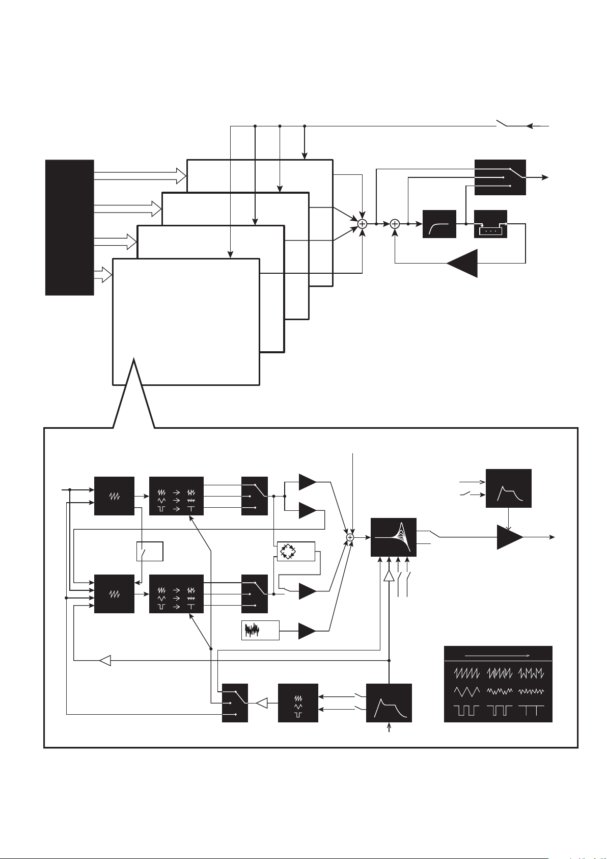
Block Diagram
OUTPUT
AUDIO
4 VOICE
ASSIGNER
VOICE 2
VOICE 1
VOICE 4
VOICE 3
pre VCF mix
pre VCF mix
pre VCF mix
pre VCF mix
HPF
FB
bypass
pre lter
post lter
DELAY
enable
INPUT
VOICE
PITCH
LFO
FM
PITCH
LFO
EG
pitch 2
EG Int
VCO 1
VCO 2 WAVE SHAPE
WAVE SHAPE
OSC
SYNC
SAW
TRI
SQR
SAW
TRI
SQR
int
NOISE
GEN
VCO1
level
CROSS MOD
depth
RING
MOD
LFO
noise
level
pre VCF mix
VCO2
level
int mod
rate mod
VCF
EG
gate
EG Int
keytrack
gate
velocity
2-pole
4-pole
velocity
0% 100%
AMP EG
VCA
wave shape amount
3
Page 4
Controls and Connections
56 78910
11 12 13 15 17 18
16
14
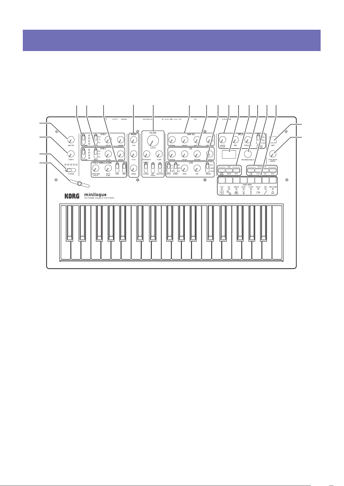
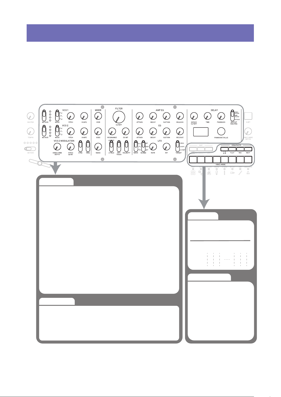
Front Panel Controls
This diagram shows the layout of the front panel knobs, switches, and buons.
1
2
3
4
MASTER knob
1.
TEMPO knob
2.
OCTAVE switch
3.
4.
5.
6.
7.
8.
Slider
VCO 1
VCO 2
OCTAVE switch
WAVE switch
PITCH knob
SHAPE knob
VCO 2 MODULATION
CROSS MOD DEPTH knob
PITCH EG DEPTH knob
SYNC switch
RING switch
MIXER
VCO 1 knob
VCO 2 knob
NOISE knob
FI LTE R
9.
CUTOFF knob
RESONANCE knob
EG INT knob
FILTER TYPE switch
KEY TRACK switch
VELOCITY switch
AMP EG
10.
EG
11.
ATTACK knob
DECAY knob
SUSTAIN knob
RELEASE knob
LFO
12.
WAVE switch
EG MOD switch
RATE knob
INT knob
TARGET switch
4
DELAY
13.
HI PASS CUTOFF knob
TIME knob
FEEDBACK knob
OUTPUT ROUTING switch
Display
14.
EDIT
15.
EDIT MODE buon
EXIT buon
WRITE buon
PROGRAM/VALUE knob
16.
SEQUENCER
17.
1–8/9–16 buons
PLAY buon
REC buon
REST buon
Buttons 1–8
18.
SHIFT button
19.
VOICE MODE DEPTH knob
20.
19
20
Page 5
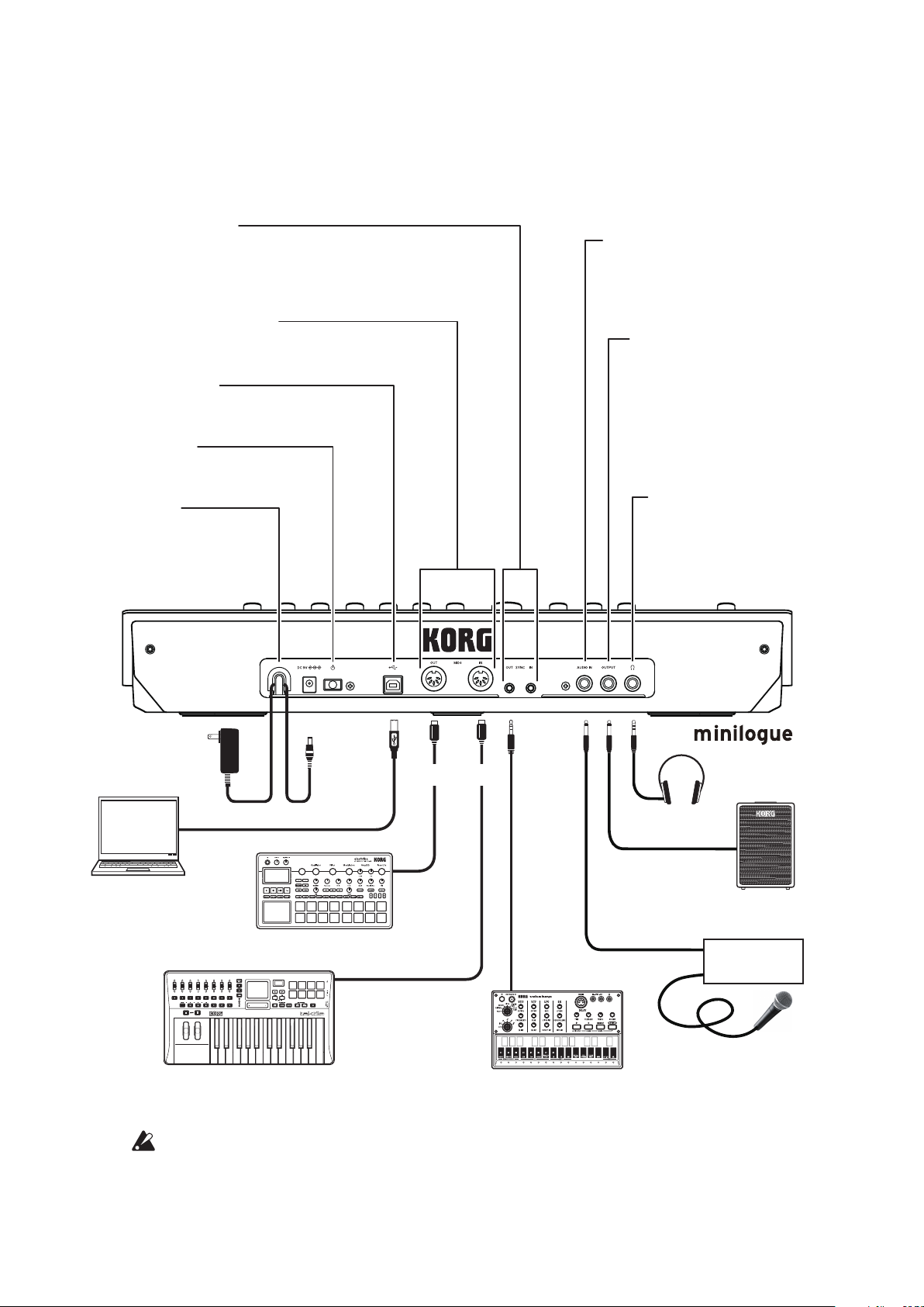
Rear Panel Connections
Cable hook
Loop the DC Plug end of the
AC Adapter cable around
this hook to prevent the cable
from being accidentally
pulled out.
USB B connector
This connector allows the minilogue to
exchange MIDI messages with your computer.
Power switch
Hold this switch in to turn the
minilogue On or Off.
MIDI IN, OUT connectors
Connect these to an external MIDI device so that MIDI
data can be transmied or received.
SYNC IN, OUT jacks
T
th
DA
ca
same sound as the OUTPUT
Groove machine
The illustration below shows a typical example of connections for the minilogue. Connect your equipment according to the needs of your own system.
he minilogue steps can be synchronized with other devices using
ese jacks. A pulse sent from the audio output of another device or
W can be used by connecting it to the SYNC IN jack. Use an 1/8"
ble (mini-phone plug) to sync with Korg volca products.
AUDIO IN jack
This standard 1/4" TS jack accepts a
mono audio signal from another
synthesizer, instrument, or external
sound source.
OUTPUT jack
This standard 1/4" TS jack
sends the sound of the
minilogue to your powered
monitoring system, mixer,
recording setup, or external
amplifier. The level is
controlled by the MASTER
knob.
Headphones jack
Connect your headphones
here. This jack outputs the
jack.
AC adapter
(included)
Computer
MIDI keyboard, rhythm machine, etc.
You must make connections with the minilogue turned o. Failure
to observe this precaution may cause malfunctions and/or damage to
your speaker system.
DC 9V jack
USB cable
USB port
Sound module, rhythm machine, etc.
MIDI OUT
MIDI IN
MIDI cable
Headphones
INPUT
Monitor speakers
(with internal amp)
OUTPUT
Mixer
SYNC IN
Microphone
5
Page 6

Turning the minilogue On and O
Before you turn the minilogue On:
Connect the AC adapter and other equipment.
Connect the included AC adapter to the DC 9V jack located on the rear
1.
panel.
Use only the included AC adapter. Using any other AC adapter may
cause malfunctions.
Plug the AC adapter into an AC outlet.
2.
Hook the AC adapter cable onto the cable hook to relieve stress on the
3.
connector and to prevent the cable from accidently being pulled out.
When disconnecting the power supply, do not use excessive force when
removing the cable from the hook. Doing so may damage the plug.
Make sure that any external output devices such as powered monitor
4.
speakers are turned o before connecting them to the minilogue.
If you want to connect a MIDI device or computer to the minilogue’s
TIP
MIDI connectors or USB B connector in order to use the minilogue’s
keyboard and controllers to control an external MIDI tone generator,
or if you want to use another MIDI keyboard or a sequencer to play
the minilogue’s sound generator, you will need to congure the settings. For details, (“Understanding MIDI”, p. 50).
Turning the minilogue On
Make sure that both the minilogue and any external output devices such
1.
as powered monitor speakers are turned o, and turn the volume of all
devices all the way down.
Hold down the Power switch on the rear panel of the minilogue; once the
2.
“minilogue” logo appears in the display, take your nger o the Power
switch.
Turn on any external output devices such as powered monitor speakers.
3.
Adjust the volume of your external output equipment, and adjust the
4.
minilogue’s volume using the MASTER knob.
6
Page 7
Turning the minilogue O
Any Program data in the minilogue that has not been saved will be lost when
the power is turned o. Be sure to save any Program and other important data
that you have edited (“Saving a Program”, p. 13).
Turn the MASTER knob of the minilogue to the left to turn the volume
1.
all the way down.
Also, turn the volume all the way down on any external output devices
that might be connected, such as powered monitor speakers.
Hold down the Power switch on the rear panel of the minilogue; to turn
2.
o the power after the display goes blank, take your nger o the power
switch.
Once you have turned the minilogue o, wait about 10 seconds before
turning the minilogue on again.
Auto Power O Feature
The minilogue features an Auto Power O feature that can automatically turn the
minilogue o after 4 hours have elapsed with no operation of the knobs, switches,
buons, or keyboard of the minilogue. By default, the factory seing for the Auto
Power O is enabled. The Auto Power O can be disabled using the steps below.
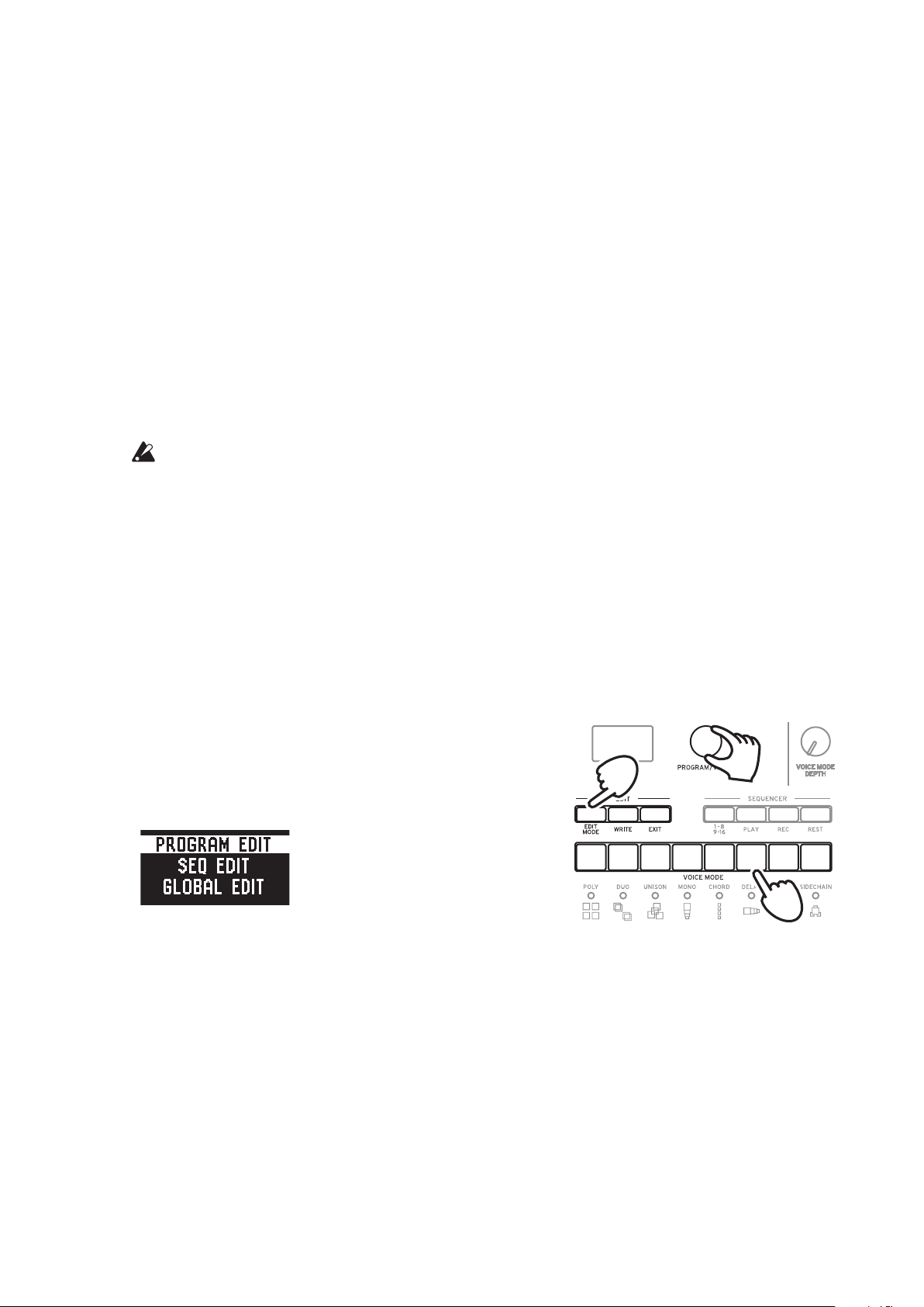
Press the EDIT MODE buon.
1.
The minilogue will enter the Edit Mode,
and the display will look like the illustration
shown below.
Turn the PROGRAM/VALUE knob, and se-
2.
lect GLOBAL EDIT.
GLOBAL EDIT can also be selected by pressing the EDIT MODE buon.
TIP
1
2, 4
6
3
Press buon 6 twice.
3.
“Auto Power O” will be displayed.
Turn the PROGRAM/VALUE knob, and select “O”.
4.
Press the EXIT buon.
5.
The minilogue will enter the Play mode, and the display will indicate the
current Program.
7
Page 8
Playing Programs and Sequences
1
Selecting and Playing a Program
The minilogue comes equipped with 200 Programs. Of those, 100 are ready-to-
play preset Programs and 100 locations are available to save your own sounds
and custom edits.
Each Program includes seings for the sound, as well as sequence data and
Voice mode seings.
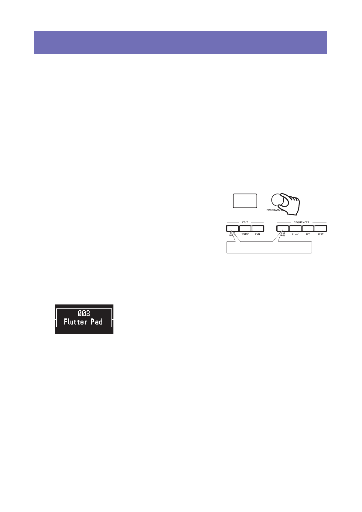
Enter the Play mode.
1.
When the minilogue is turned on, it will automatically enter the Play mode.
In the Play mode, verify that all of the EDIT MODE and 1–8/9–16 buons
on the front panel are unlit.
If the EDIT MODE buon or the 1–8/9–
TIP
16 buon is lit, press the EXIT buon.
The PLAY or REC buons will light to
indicate when the sequence data saved
in a Program is being played back or is
recording. You can still select other Pro
grams in this state, but press the PLAY
buon if you wish to stop the Sequencer.
-
Make sure they are unlit.
2
Turn the PROGRAM/VALUE knob to select a Program.
2.
The display will indicate the Program name and number.
The minilogue comes with 100 preset Programs (001–100) as part of the factory preload data. These preset Programs are instantly accessible and ready
for you to enjoy. For details, refer to “Program List” (p. 54).
Hold down the SHIFT buon while turning the PROGRAM/VALUE
TIP
knob to skip through the Program List in increments of 10.
In addition to showing Program name and number, the display can
TIP
also be used as an oscilloscope, to show the electrical signals created
by the waveform of the sound. For details on the display, refer to “Oscilloscope” (p. 45).
8
Page 9
Adjusting the OCTAVE range, using the Slider, and changing the Voice
3.
Mode.
As you play, you can use the ve-way OCTAVE Switch to
transpose the playing area of the keyboard by ± 2 octaves.
In addition, you can move the Slider from left to right to add
real-time performance control.
The parameter assigned to the slider will vary depend-
TIP
ing on the Program. Rrefer to “Program List” (p. 54)
to see which parameter is assigned to the slider in each
Program.
The Slider Assign function in PROGRAM EDIT mode is
TIP
used to assign parameters to the slider (“Slider Assign”, p. 33).
In the Play mode, the LEDs below buons
1–8 show the Voice mode status of the cur
rent Program. You can use these buons
1–8 to switch between the dierent modes.
For details, refer to “Voice modes” (p. 23).
-
12345678
Using Favorites
Recalling your Favorite Programs
The minilogue includes a Favorites func-
tion, which can be used to instantly recall
any one of the up to eight Programs that
you have previously registered as Favorites
on the minilogue.
In the Play mode, press one of the but-
1.
tons from 1–8 while holding down the
SHIFT buon.
The Favorite Program previously registered to that buon will be recalled, and
the Program name and number will be
indicated in the display.
12345
1
6
8
7
1
9
Page 10
Registering your Favorite Programs
2, 3
You can register up to eight Programs that you particularly like as Favorite
Programs.
In Play mode, turn the PROGRAM/
1.
VALUE knob to select a Program you
like.
The display will indicate the Program
name and number.
Hold down one of the buons from
2.
1–8 while keeping the SHIFT buon
pressed.
The Program will be registered as a Favorite program, and “Registered to Favorite” will be indicated in the display.
The favorite Programs that you
TIP
register will be saved in the Global seings.
12345
1
6
8
7
2
2
Playing the Sequencer
Each Program in the minilogue includes sequence data. In this section, we’ll
play the sequence data saved as part of the preset Programs.
Turn the PROGRAM/VALUE knob to select
1.
a Program.
The display will indicate the Program name
and number.
Press the PLAY buon in the SEQUENCER
2.
section.
The sequence data that is recorded in the current Program will begin playing.
The 1–8 buons will light up in steps while the sequencer is playing.
The Sequencer tempo is set for each Program in the SEQ EDIT mode
TIP
and saved as part of the Program, but you can adjust the tempo from
56.0 to 240.0 BPM (Beats Per Minute) by turning the TEMPO knob.
1
Press the PLAY buon once more to end the Sequencer playback.
3.
10
Page 11
Programs
Program Architecture
Each minilogue Program includes seings for the Oscillators, Mixer, Filter, EGs
and LFO, as well as a 16-Step Sequencer plus Eects.
Try editing each related parameter, and enjoy changing the sounds of the mini-
logue.
Basic Parametres
VCO 1
OCTAVE
WAVE
PITCH
SHAPE
VCO 2
OCTAVE
WAVE
PITCH
SHAPE
VCO 2 MODULATION
CROSS MOD DEPTH
PITCH EG INT
SYNC
RING
Detail Parametres
PROGRAM NAME
Slider Assign
Bend Range +
Bend Range −
MIXER
VCO1
VCO2
NOISE
FILTER
CUTOFF
RESONANCE
EG INT
FILTER TYPE
KEYTRACK
VELOCITY
AMP EG
ATTACK
DECAY
SUSTAIN
RELEASE
LFO BPM Sync
LFO Key Sync
LFO Voice Sync
EG
ATTACK
DECAY
SUSTAIN
RELEASE
LFO
WAVE
EG MOD
RATE
INT
TARGET
DELAY
HI PASS CUTOFF
TIME
FEEDBACK
OUTPUTROUTING
Portamento Time
Portamento Mode
Portamento BPM
Amp Velocity
Program Level
Sequence Data
NOTE [STEP 1–16]
GATE TIME [STEP 1–16]
3 15 16
STEP
NOTE
GATE
Sequence Parameters
1𝅘𝅥𝅮2
𝅘𝅥
BPM
Step Length
Step Resolution
Swing
Default Gate Time
Motion Type (1–4)
Motion Enable (1–4)
Motion Smooth (1–4)
14
𝅘𝅥𝅮
𝅘𝅥
11
Page 12

Creating Sounds
Editing a program means changing the Program’s parameters to alter its
sound.
There are two way to create sounds on the minilogue.
Select an existing Program that’s close to the sound you want, and edit that
•
Program’s parameters to achieve your own custom sound.
You can also initialize all the Program parameters or use the Panel Load func-
•
tion to create your own sound from scratch.
Editing an Existing Program
In Program mode, select the Program that you want to use as a starting
1.
point.
Use the knobs and switches on the front panel.
2.
Take a moment to consider the dierences between the current Program
and the sound you have in mind, and use the front panel controls to edit
the necessary parameters.
For details on how the pitch, sound, and volume change when using the
TIP
knobs and switches, refer to “Basic Parameter Editing” (p. 14).
We recommend that you save the Program on the minilogue after
editing the sound. Any edits that you make will be lost if you turn o
the power or recall a dierent Program. For details, refer to “Saving a
Program” (p. 13).
Creating a Program from Scratch
To create a sound from scratch, we recommend that you use the Panel Load
function. This will load the current seings of each front panel control and
provide a simple starting point for your iconic creations.
As you explore the front panel controls, you can see how each parameter will
aect the sound, making it easier to understand how each section of the mini-
logue functions and how the parameters interact.
Panel Load function
Press the PLAY buon while holding down the SHIFT buon. The sound will
change to reect the panel seings, and “Load Panel” will be indicated in the
display.
12
Page 13

Saving a Program
We recommend that you save your Program on the minilogue after editing the
sound.
Any edits that you make to the current program will be lost if you
turn o the power or recall a dierent program before saving.
Edit the program in Play mode.
1.
For details, refer to “Basic Parameter Editing” (p. 14).
Press the WRITE buon; the minilogue will enter the Write standby
2.
mode, and the WRITE buon will blink.
The message “Where to write?” will appear in the display.
Turn the PROGRAM/VALUE knob to select the Program number where
3.
your new sound will be saved.
Programs 1–100 are preset Programs, and Programs 101–200 are user Programs.
Press the EXIT buon to cancel the operation.
TIP
Press the WRITE buon once more.
4.
The Program will be saved in internal memory, and the message “Complete” will appear in the display..
Never turn o the power while Programs are being saved. Doing so
may destroy the internal data.
13
Page 14
Basic Parameter Editing
In this section, we’ll explain the basic parameters that make up a program.
The basic parameters are assigned to the knobs and switches on the front panel.
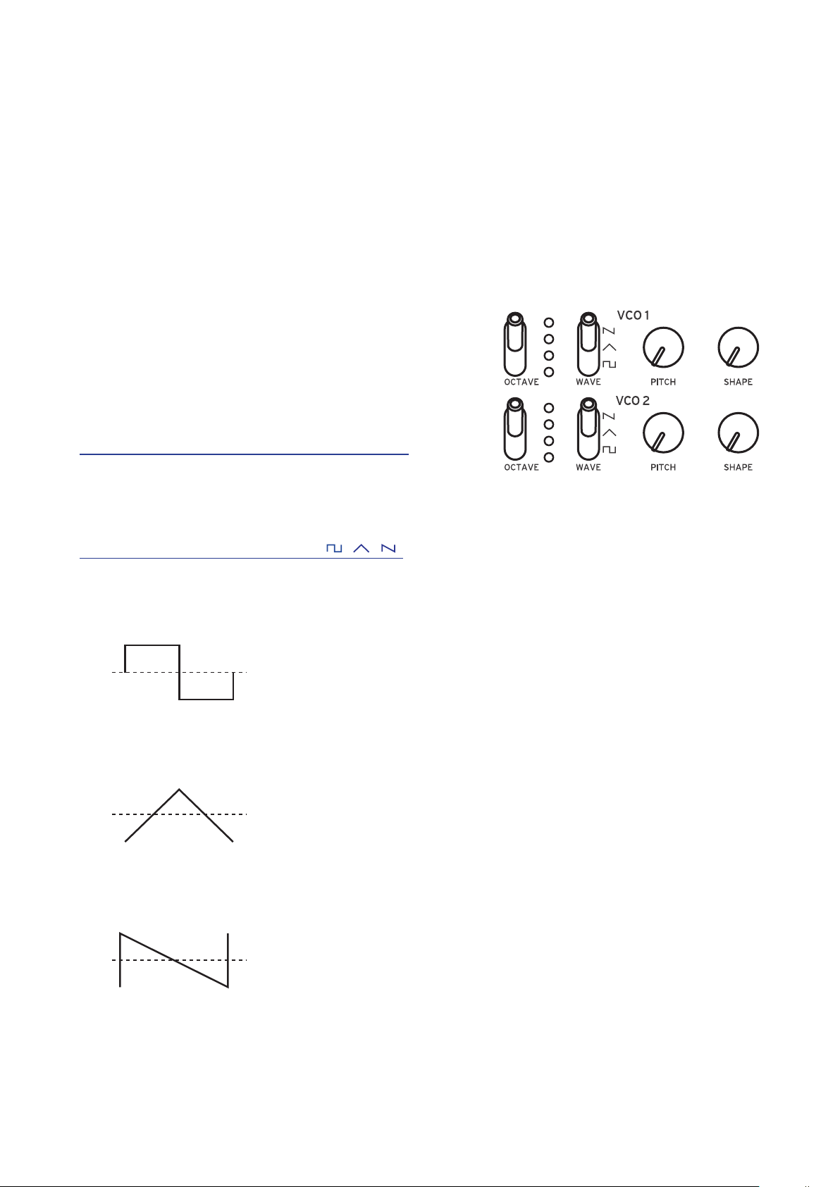
VCO 1, VCO 2
VCO: Voltage Controlled Oscillator
There are two oscillators in the minilogue. Oscillator Parameters include the seings for the
pitch of the sound (OCTAVE, PITCH) and the
waveform (WAVE, SHAPE).
O C T A V E s w i t c h [ 1 6 ’, 8 ’, 4 ’, 2 ’ ]
The pitch of oscillators 1 and 2 can be set in
octave steps.
WAVE switch [ , , ]
This sets the waveforms for oscillators 1 and 2.
Square wave: This waveform is used for electronic and wind instrument
sounds.
Triangle wave: This waveform has a rounder feel than the sawtooth or square
wave.
Sawtooth wave: This waveform is used to create sounds typical of analog syn-
thesizers, such as synth basses and brass.
14
Page 15
PITCH knob [−1200...+1200]
0 1023
The pitch, or tuning, of the Oscillators can be set using one-cent steps.
SHAPE knob [0...1023]
This knob will determine the nal shape, complexity, or duty-cycle (Square) of
the selected waveform.
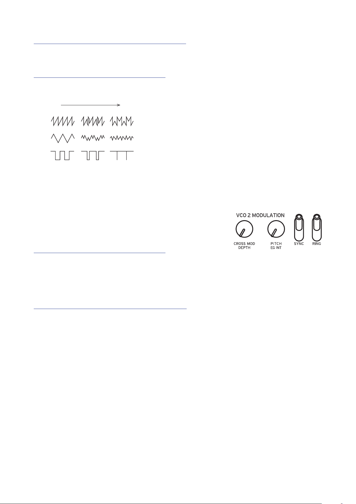
VCO 2 MODULATION
Oscillator 2 includes powerful oscillator sync, cross
modulation, and ring modulation functions.
CROSS MOD DEPTH knob [0...1023]
Cross Mod (Modulation) allows Oscillator 1 to mod-
ulate the pitch of Oscillator 2.
Turning the knob to the right results in stronger modulation.
PITCH EG DEPTH knob [−4800...+4800]
The Pitch EG (Envelope Generator) can be used to change the Pitch of Oscilla-
tor 2 over time. In the center position, no eect is applied.
Positive values (turning the knob to the right of center) increase the Pitch EG
eect; turning the knob to the left of center increases the Pitch EG eect using
an inverted image of the EG shape (negative values).
To learn more about the EG seings, refer to “EG” (p. 20).
15
Page 16
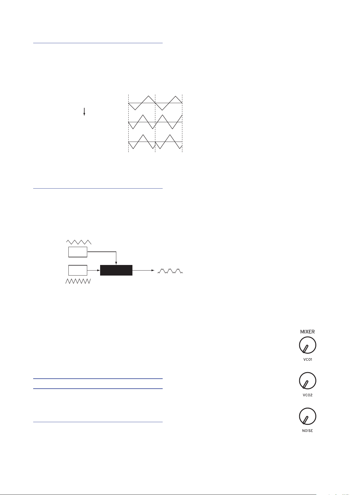
SYNC switch [OFF, ON]
Oscillator sync is a popular eects for creating edgy synth leads.
ON (up position):
With this type of modulation, the phase of oscillator 2 is forcibly synchronized to the phase of oscillator 1. This adds harmonic overtones to
the frequency of oscillator 2, making a complex waveform.
VCO 1 Wave
Sync
VCO 2 Wave (original)
VCO 2 Wave (output)
RING switch [OFF, ON]
Ring Modulation outputs the sum and dierence of the frequencies created by
the two oscillators. Adjust the pitch of Oscillator 2 to create non-tonal and metallic sounds.
ON (up position): Oscillator 1 is used to ring modulate oscillator 2.
VCO 1
VCO 2
RING MOD
MIXER
D
The mixer is used to set the relative levels of the three signal sources—
Oscillator 1, Oscillator 2, and the Noise generator before they enter the
lter.
VCO 1 knob [0...1023]
VCO 2 knob [0...1023]
These knobs control the output levels of oscillator 1 and 2.
NOISE knob [0...1023]
Use this knob to set the output level of the noise generator.
Noise (white noise) can be used on its own, or mixed with the Oscillators to create percussion instrument sounds, or sound eects such as surf.
16
Page 17
FILTER
Low resonance value High resonance value
VCF: Voltage Controlled Filter
The low-pass lter shapes the tone by selectively ltering certain parts of the harmonic spectrum of the sound generated
by the Oscillators and the Noise generator.
CUTOFF knob [0...1023]
This knob is used to set the cuto frequency. Harmonic content above the cuto frequency will be ltered out.
Turning the knob to the left will lower the cuto frequency,
and turning the knob to the right will raise the cuto frequency.
If the CUTOFF value is set too low, the volume may
be extremely low.
RESONANCE knob [0...1023]
Also known as Peak or Q, the RESONANCE control adds additional emphasis
to the overtones occurring at the CUTOFF frequency, giving a distinctive char-
acter to the sound.
Turning the knob to the right will increase the resonance eect.
The overtones that are emphasized will change depending on the cut-
TIP
o frequency. For this reason, it’s good to adjust the CUTOFF knob
while adjusting the RESONANCE knob.
When emphasizing the overtones in this way, the sound may distort
depending on the cuto frequency or the input audio.
17
Page 18
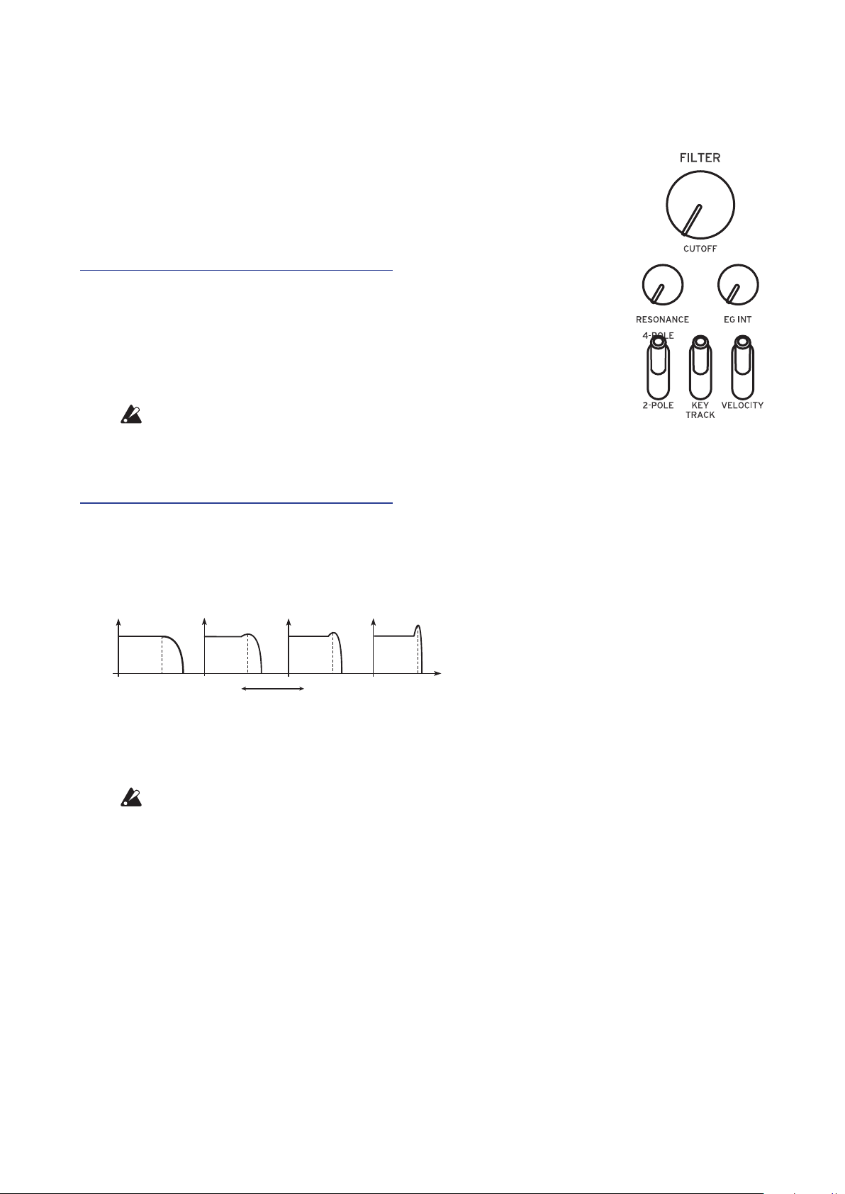
EG INT knob [−100%...0...+100%]
Cuto
Time
Cuto
Time
dB
10k
The Envelope Generator (EG) can be used to control the CUTOFF, or Filter fre-
quency, over time using this EG INT (intensity) knob.
To learn more about the EG seings (“EG”, p. 20).
With this knob in the center position (0%), no EG is applied to the Filter.
Rotating the knob to the left of center increases the EG intensity, but with the
polarity of the EG inverted.
Note on
Note o
Rotating the knob to the right of center increases the EG intensity eect.
Note on
Note o
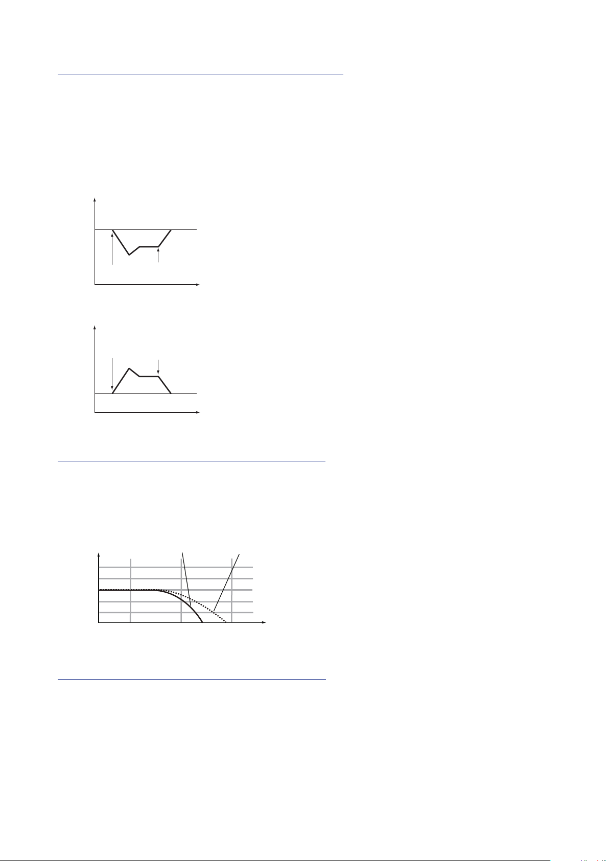
FILTER TYPE switch [2-POLE, 4-POLE]
The lter type (roll o) can be set to either 2-POLE (12 dB per octave) or
4-POLE (24 dB per octave).
2-POLE: Gently cuts o the upper harmonics, creating a more natural sound.
4-POLE: Cuts o the upper harmonics more sharply than the 2-POLE.
4-POLE
2-POLE
24
12
0
-12
-24
24 100 1k
Hz
KEY TRACK switch [0%, 50%, 100%]
Key tracking allows the note played on the keyboard to inuence the cuto
frequency of the lter. This is useful when you want higher notes to have more
upper harmonics, or to appear brighter, than lower notes.
0% (lower position): No keyboard tracking will be applied.
50% (center position): The cuto frequency will change at half the rate/slope as
the pitch of the keyboard.
100% (upper position): The cuto frequency will change at the same rate/slope
as the pitch of the keyboard.
18
Page 19

VELOCITY switch [0%, 50%, 100%]
Attack Level
Time
Level
Species how the velocity (keyboard playing dynamics) will aect the cuto
frequency, allowing louder notes to appear brighter, etc.
0% (lower position): Velocity will not aect the cuto frequency.
50% (center position): Velocity will aect the cuto frequency, but at only half
the amount produced at 100%.
100% (upper position): Playing the keys harder will increase the cuto frequency, while playing the keys softer will decrease the cuto frequency.
AMP EG
VCA: Voltage Controlled Amplier / EG: Envelope Generator
The AMP (VCA) controls the output level of
the minilogue, before the Master control. The
AMP Envelope Generator provides a precise
control signal that varies over time to modify
the VCA level.
ATTACK knob [0...1023]
The ATTACK species the time required for the EG to reach its maximum level
once a new note is played
DECAY knob [0...1023]
The DECAY species the time required for the EG to fall to the preset Sustain
level once the Aack portion of the EG is complete.
SUSTAIN knob [0...1023]
The SUSTAIN species the level that will be maintained while the key is held
down (or a trigger is applied).
RELEASE knob [0...1023]
The RELEASE species the time required for the EG to reach its minimum level
(zero) once the key or trigger is released.
Note on Note o
Sustain
0
Attack
Time
Decay
Time
Level
Release
Time
19
Page 20

EG
Time
EG: Envelope Generator
The EG provides a precise control signal that
varies over time. This signal can be used to
modify the Pitch of Oscillator 2, the Filter
CUTOFF frequency, and the Speed or Intensi-
ty of the LFO. The EG signal is available at the VCO 2 MODULATION PITCH
EG INT knob, the FILTER EG INT knob, and the LFO EG MOD switch. This
switch can be set to allow the EG signal to control either the RATE or INT (In-
tensity), in conjunction with the LFO RATE and INT knobs.
Note on Note o
Sustain Level
Cuto
Attack
Time
Decay
Time
Release
Time
ATTACK knob [0...1023]
The ATTACK species the time required for the EG to reach its maximum level
once a new note is played.
DECAY knob [0...1023]
The DECAY species the time required for the EG to fall to the preset Sustain
level once the Aack portion of the EG is complete.
SUSTAIN knob [0...1023]
The SUSTAIN species the level that will be maintained while the key is held
down (or a trigger is applied).
RELEASE knob [0...1023]
The RELEASE species the time required for the EG to reach its minimum level
(zero) once the key or trigger is released.
20
Page 21

LFO
LFO: Low Frequency Oscillator
The Low Frequency Oscillator creates a repeating cyclical signal. You can choose one
of three LFO waveforms.
Depending on its target, the LFO can provide vibrato (PITCH); Tonal changes to the
Oscillators (SHAPE); or Wah-Wah (CUTOFF) eects
WAVE switch [ , , ]
The LFO can be set to a square wave ( ), a triangle wave ( ), or a sawtooth
wave (
EG MOD switch [OFF, RATE, INT]
The EG can modify either the speed (RATE) or depth (INT) of the LFO, in conjunction with the RATE and INT knobs.
).
RATE knob [0...1023 / 4, 2, 1, 0, 3/4...1/64]
The rate knob adjusts the speed of the LFO.
Turning the knob to the right will increase the LFO speed.
The values indicated here depend on the LFO BPM Sync seings in
TIP
the PROGRAM EDIT mode. When LFO BPM Sync is O, the available values are 0–1023; and when LFO BPM Sync is On, the available
values are from 4–1/64 (“LFO BPM Sync”, p. 34).
INT knob [0...1023]
The INT knob adjusts the intensity of the LFO.
Turning the knob to the right will increase the LFO intensity.
TARGET switch [CUTOFF, SHAPE, PITCH]
Selects the parameter where the LFO modulation will be applied.
CUTOFF: Modulation is applied to the FILTER CUTOFF knob seing.
SHAPE: Modulation is applied to the VCO 1, 2 SHAPE knob seings.
PITCH: Modulation is applied to the VCO 1, 2 PITCH knob seings.
21
Page 22

DELAY
The Delay eect is combined with a High
Pass lter. This allows you to create a wide
range of sounds.
HI PASS CUTOFF knob [0...1023]
Adjusts the cuto frequency of the high-pass lter. Sounds and harmonic components below the HI-PASS CUTOFF frequency will be aenuated.
Turning the knob to the right will increase the cuto frequency.
TIME knob [0...1023]
This knob species the delay time.
Turning the knob to the right will make the delay time longer.
FEEDBACK knob [0...1023]
The Feedback knobs controls the regeneration of the Delay eect.
Turning the knob to the right will increase the amount of feedback.
OUTPUT ROUTING switch [BYPASS, PRE FILTER, POST FILTER]
Using this switch, you can specify where in the signal chain the Delay eect is
being applied.
The circuit routing is shown below. Also, refer to the block diagram (“Block
Diagram”, p. 3).
BYPASS: In this mode, the Delay and Hi Pass Filter are bypassed, and no eect
is applied to the sound.
PRE FILTER: The original sound is output before the Hi Pass Filter, and the Hi
Pass Filter is applied only to the delayed sound.
POST FILTER: This Hi Pass Filter is applied to both the original (dry) sound,
and the delayed sound.
22
Page 23

Voice modes
12345678
The minilogue is a 4-voice analog synthesizer. By changing the Voice
mode, you can combine and allocate the voices in dierent ways.
The Voice mode is set as a Program parameter,
and you can see which Voice mode is being used
by looking at which of the buons 1–8 is lit. For
details, refer to “Program List” (p. 54).
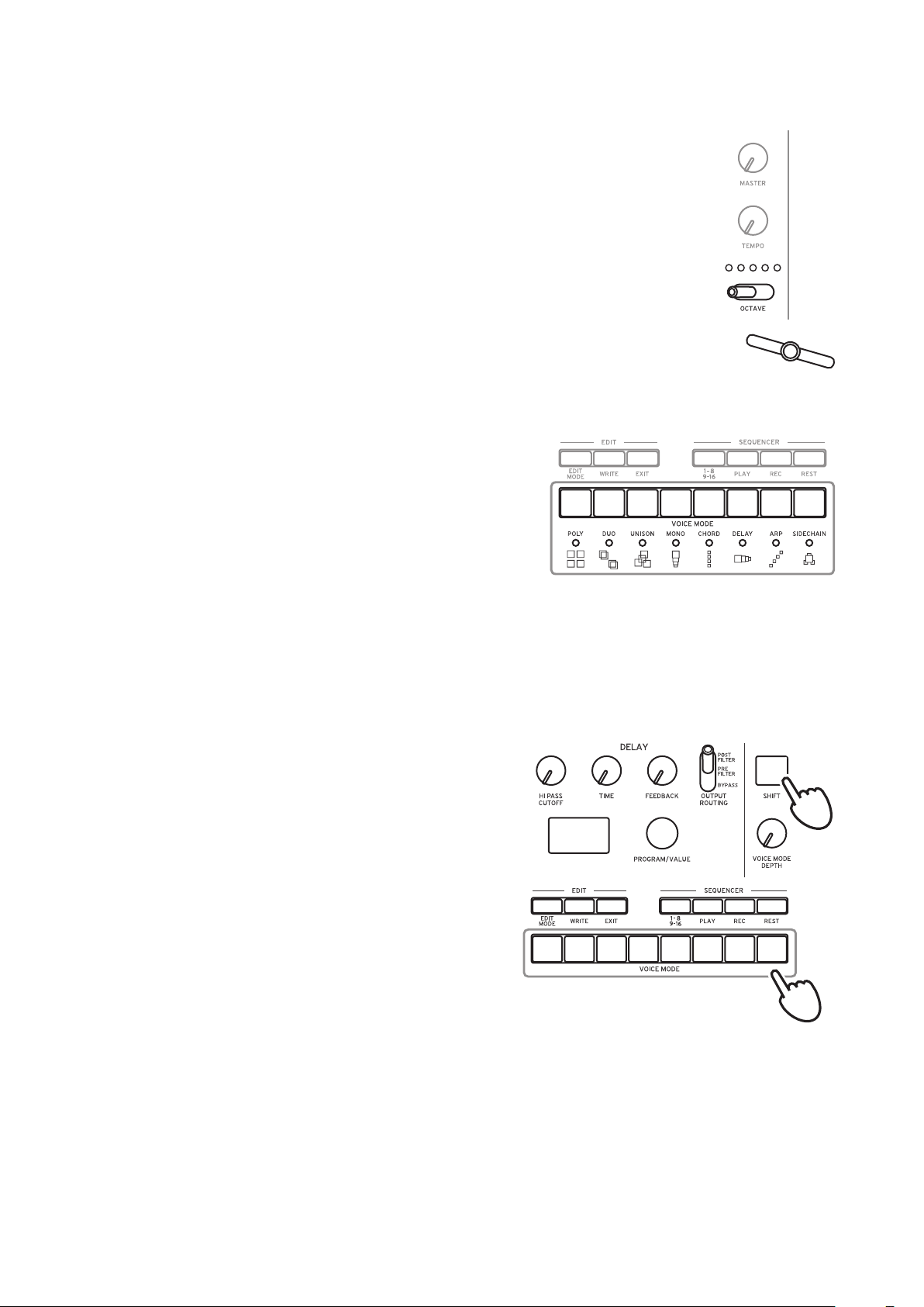
There are 8 dierent Voice modes, and buons
1–8 are used to switch between them. Turning
the VOICE MODE DEPTH knob controls a spe-
cic parameter unique to each Voice mode.
Voice mode list
Button
1
2
3
4
Voice mode Action VOICE MODE DEPTH knob eect
[Invert 0...8]
Plays an inverted form of the chord
that you play on the keyboard. Turn
ing the knob right will invert the
chord upwards.
[Detune 0C...50C]
Turning the knob to the right will
increase the detuning eect.
[Detune 0C...50C]
Turning the knob to the right will
increase the detuning eect.
[Sub 0...1023]
Turning the knob to the right will
assign voices 2 and 3 as a sub-oscil
lator one octave lower, and turning
the knob to the right once more will
assign voice 4 as a sub-oscillator two
octaves lower.
POLY
DUO
UNISON
MONO
Used for basic playing as a
4-voice poly synth.
The 4 voices will be stacked
together into 2 pairs of 2 voices
in unison, as a 2-voice poly
synth.
The 4 voices will be stacked
together into a single voice in
unison, as a mono synth.
The 4 voices will operate as a
mono synth with sub-oscillator.
-
-
5
CHORD
The four voices will play as a
chord.
23
[5th, sus2, m, Maj, sus4, m7, 7, 7sus4,
Maj7, aug, dim, m7♭5, mMaj7, Maj7♭5]
Selects the chord to play.
Page 24

Button
Voice mode Action VOICE MODE DEPTH knob eect
6
DELAY
7
ARP
8
SIDE CHAIN
Voices 2, 3, and 4 will play in
delayed sequence after voice 1
plays.
Uses the arpeggiator to play up
to 4 voices.
Lowers the volume of the previously-played voice when a
new voice is played.
[1/192...1/4]
Turning the knob to the right will
make the delay time longer.
[MANUAL 1, MANUAL 2, RISE 1,
RISE 2, FALL 1, FALL 2, RISE FALL 1,
RISE FALL 2, POLY 1, POLY 2, RAN
DOM 1, RANDOM 2, RANDOM 3]
Selects the arpeggiator type.
[Depth 0...1023]
Turning the knob to the right will
increase the volume range by which
the previously-played voice is re
duced.
-
-
24
Page 25

Sequencer
In this section, we’ll explore real-time recording, step recording, and motion se-
quence recording, as well as how to edit the recorded sequences (step edit).
Real-Time Recording
Recording a performance
This feature allows you to record your minilogue keyboard performance and
to add overdubs in real time.
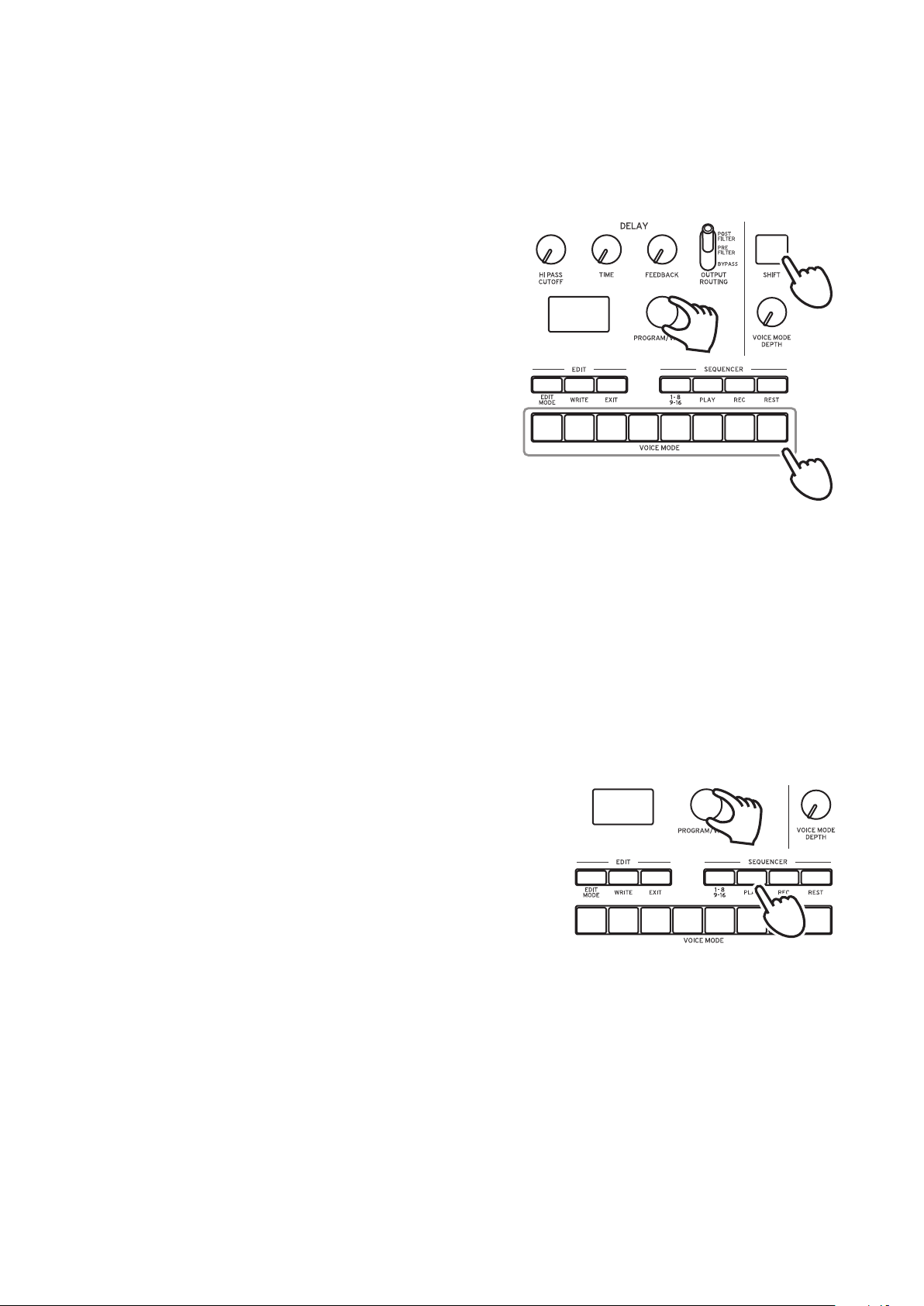
Press the PLAY buon in the SEQUENCER
1.
section to play the sequencer.
The PLAY buon will light.
1
Press the REC buon.
2.
Real-time recording will begin, and the REC
buon will light.
Play the keyboard.
3.
The notes that you play on the keyboard will be overdubbed (added to the
recording of the sequence data).
Press the REC buon once more to stop the recording.
4.
The REC buon will go dark.
Press the REC buon once more to start recording again.
TIP
Press the PLAY buon to nish real-time recording.
5.
The PLAY buon will go dark.
Deleting the sequencer data
2
Press the REST buon to erase or delete existing notes in the sequence during
real-time recording.
25
Page 26

Step Recording
Press the REC buon in the SEQUENCER section while the sequencer is
1.
stopped.
“STEP REC” and “STEP 1” will be indicated in the display.
If the sequence has already been recorded, the note names will be indicated
in the display.
Select the step you wish to edit. Use buons 1–8 to select steps 1–8, and
TIP
use buons 1–8 while holding the SHIFT buon to select steps 9–16.
Use the keyboard, REST buon and other controls to edit the notes.
2.
When you record a note, rest, or tie in step mode, the display will automatically move to the next step.
Recording notes
The note name for the keys you press on the keyboard will be indicated in
the display. Check the note name in the display, and if it is correct, release
your nger to record that note and to move to the next step.
If the note name is not correct, just play the correct key while continuing
to hold down the wrong key. Check the note indicated in the display, and
take your nger o the keyboard to move to the next step.
You can also record chords that you play on the keyboard. The number of
notes in a chord will depend on the Voice mode of the current Program
(“Voice modes”, p. 23).
The note length during recording is determined by the Default Gate
TIP
Time value that is set in the SEQ EDIT mode. If you turn the PROGRAM/ VALUE knob while playing the keyboard, the gate time for
only the note(s) you played will be changed when recording.
Recording a rest
You can record a rest by pressing the REST buon.
Recording a tie
Press the REST buon while holding down a key. The note will be tied to
the next note and recorded.
When the set number of steps have nished recording, step recording
3.
will automatically end. Pressing the REC buon at any step during recording will stop the step recording at that step.
The number of steps is set for each Program, and you can change
TIP
the number of steps using the Step Length function in the SEQ EDIT
mode. For details, refer to “Step Length” (p. 37).
26
Page 27

Recording a Motion Sequence
Motion Sequencing allows you to record the ipping of switches and the turning of knobs as part of the sequence, and recreate those motions automatically
during playback.
Four Motion Sequences can be recorded on the minilogue, which can includes
changes to all knobs and switches (except for the MASTER knob, TEMPO
knob, and OCTAVE switches).
Press the PLAY buon to play the sequencer.
1.
Press the REC buon.
2.
Real-time recording will begin.
Move the knobs and switches on the minilogue.
3.
A Motion Sequence of the knobs and switches you moved will be recorded.
You can record up to 4 Motion Sequences for the knobs and switches.
If you exceed this limit, the message “Motion Full” will be indicated in
the display, and the display will enter MOTION CLEAR in the SEQ EDIT
mode. When this happens, delete a previously-recorded Motion Sequence
before recording a new one (“Deleting a Motion Sequence”, p. 28).
After the set number of steps have nished recording, the Motion Se-
4.
quence will automatically nish recording as well.
Up to 4 Motion Sequences can be recorded, which includes changes to the
knobs and switches. Knobs and switches that have already been recorded
can be rerecorded as well.
The number of steps is set for each Program, and you can change the
TIP
number of steps using the “Step Length” function in the SEQ EDIT
mode. For details, refer to “Step Length” (p. 37).
27
Page 28

Deleting a Motion Sequence
If you try to record a fth Motion Sequence, the message “Motion Full” will be
indicated in the display. When this happens, the display will enter MOTION
CLEAR in the SEQ EDIT mode, and you will be able to delete one of the previously recorded Motion Sequences.
Check that the minilogue is on the MOTION CLEAR function, in the
1.
SEQ EDIT mode.
“MOTION CLEAR” will be indicated in the display. You can delete Motion
Sequences one at a time here.
Press the EXIT buon to cancel deleting the Motion Sequence.
TIP
Press buon 4, and select the motion to delete.
2.
Turn the PROGRAM/VALUE knob to select
3.
the message “CLEAR...?”.
4
Press the WRITE buon.
4.
The selected Motion Sequence will be deleted.
Press the EXIT buon.
5.
To continue recording a Motion Sequence, press the REC buon, and
6.
press the PLAY buon to stop.
To delete all Motion Sequences at once, use the “Motion Clear” func-
TIP
tion assigned to buon 3 in the SEQ EDIT mode. For details, refer to
“Motion Clear” (p. 38).
2
3
28
Page 29

Editing sequence data (step edit)
2, 3
Using Step Edit, you can change the values of notes and gate times previously
recorded into a sequence.
Select the Program that includes the sequence data you wish to edit.
1.
Press the 1–8/9–16 buon.
2.
“STEP EDIT 1–8” and “STEP EDIT
9–16” will be indicated in the display.
The number of steps is set for
TIP
each Program, and you can
12345
change the number of steps by
turning the PROGRAM/VAL
-
UE knob while holding down
the SHIFT buon. You can also
change the number of steps using
the “Step Length” function in the SEQ EDIT mode. For details, refer
to “Step Length” (p. 37).
6
8
7
3
Select the step that you want to edit.
3.
To change steps 1–8: Select STEP EDIT 1–8, and then press the one of the
buons from 1 to 8.
To change steps 9–16: Select STEP EDIT 9–16, and then press the one of the
buons from 1 to 8.
The display will indicate “Note”. Play the keyboard to record notes.
Next, press the same buon to show the “Gate Time” message in the display, and use the PROGRAM/VALUE knob to change the value.
Button 1
STEP 1/9
Note Note Note Note Note Note Note Note
∧
Buon 1
∨
Gate Time Gate Time Gate Time Gate Time Gate Time Gate Time Gate Time
TIP
Button 2
STEP 2/10
∧
Buon 2
∨
Button 3
STEP 3/11
∧
Buon 3
∨
Button 4
STEP 4/12
∧
Buon 4
∨
Button 5
STEP 5/13
∧
Buon 5
∨
Button 6
STEP 6/14
∧
Buon 6
∨
Button 7
STEP 7/15
∧
Buon 7
∨
Button 8
STEP 8/16
Buon 8
Gate Time
If you hold down the SHIFT buon while pressing a buon from 1 to
8 that is assigned to the current step, you can delete the note.
∧
∨
If no note has been recorded, there will be no gate time.
Press the EXIT buon once you are nished with step editing.
4.
29
Page 30

Other editing functions
Use the SEQ EDIT mode when seing the Step Length and Step Resolution
parameters during sequence step recording, as well as for deleting sequence
data, or for editing or deleting motions. For details, refer to “SEQ EDIT mode”
(p. 37).
30
Page 31

Edit Mode
Although nearly all of the minilogue’s main parameters can be edited using the
knobs and switches on the panel, other detailed parameters are accessed using
the Edit mode.
There are three sub-modes within the Edit mode: PROGRAM EDIT mode,
SEQ EDIT mode, and GLOBAL EDIT mode.
How to enter the Edit mode
Press the EDIT MODE buon.
1.
Each Edit mode is shown in the display,
and the buons light.
1, 2
2
1234567
Press the EDIT MODE buon repeatedly—
2.
or use the PROGRAM/VALUE knob—to
advance to the PROGRAM EDIT mode,
SEQ EDIT mode, or GLOBAL EDIT mode.
PROGRAM EDIT mode: This mode is used to change the Program name
and assign a parameter to the slider, as well as to initialize Programs and
perform other Program editing functions.
SEQ EDIT mode: This mode is used to set the BPM and congure other
Step Sequencer seings, to delete sequence data, and so on.
GLOBAL EDIT mode: This mode is used to set the tuning and to specify
how the knobs and switches should function, as well as seings that aect
the entire synthesizer—such as MIDI.
Press one of the buons 1–6 (or buons 1–7 in GLOBAL EDIT mode).
3.
The minilogue will enter the selected Edit mode, and the parameter names
will be indicated in the display.
Switch to a dierent page by pressing the same buon in succession.
3
Buons 1–6 are assigned to specic Edit pages in the PROGRAM EDIT
mode and the SEQ EDIT mode (“PROGRAM EDIT mode”, p. 33) (“SEQ
EDIT mode”, p. 37).
Buons 1–7 are assigned to specic Edit pages in the GLOBAL EDIT mode
(“GLOBAL EDIT mode”, p. 40).
31
Page 32

After you have congured the parameters in PROGRAM EDIT mode
4.
and/or SEQ EDIT mode, press the WRITE buon to save your changes.
The display will indicate the message “Where to write?”.
If you do not save your changes and select another Program after you
have congured the parameters in the PROGRAM EDIT mode and
the SEQ EDIT mode, your seings will be lost.
GLOBAL EDIT mode parameters are automatically saved when you
TIP
switch pages, so there is no need to save them manually.
Use the PROGRAM/VALUE knob to select the destination Program num-
5.
ber where you will save your edited sound.
Press the EXIT buon to cancel the save operation and return to Play mode.
Press the WRITE buon to save the seings and return to the Play mode.
6.
32
Page 33

PROGRAM EDIT mode
The parameters of the PROGRAM EDIT mode are assigned to buons 1–6.
Button 1 Button 2 Button 3 Button 4 Button 5 Button 6
PROGRAM
NAME
PROGRAM
NAME
SLIDER FUNC LFO SETTING
Slider Assign
Bend Range + LFO Key Sync
Bend Range −
LFO BPM
Sync
LFO Voice
Sync
OTHER SET
TING
Portamento
Time
Portamento
Mode
Portamento
BPM
Amp Velocity
Program Level
INITIALIZE DUMP
Initialize
Button 1 (PROGRAM NAME)
You can create a Program Name up to 12 characters in length.
Program
Dump
Rotate the PROGRAM/VALUE knob to select the desired character, then press
buon 1 to move the cursor to the next position.
Button 2 (SLIDER FUNC)
The Slider oers real-time control over a specic parameter of your choosing.
In addition, the slider can be used as a pitch bend controller.
Slider Assign [PITCH BEND...VOICE MODE DEPTH]
You can assign any one these performance parameters to the slider:
PITCH BEND
GATE TIME
VCO 1 PITCH
VCO 1 SHAPE
VCO 2 PITCH
VCO 2 SHAPE
CROSS MOD DEPTH
VCO 2 PITCH EG INT
33
Page 34

VCO 1 LEVEL
VCO 2 LEVEL
NOISE LEVEL
CUTOFF
RESONANCE
FILTER EG INT
AMP EG ATTACK
AMP EG DECAY
AMP EG SUSTAIN
AMP EG RELEASE
EG ATTACK
EG DECAY
EG SUSTAIN
EG RELEASE
LFO RATE
LFO INT
HPF CUTOFF
DELAY TIME
FEEDBACK
PORTAMENTO
VOICE MODE DEPTH
Bend Range + [1 Note...12 Note]
If the Slider is set to PITCH BEND, this parameter species how much pitch
bend will be applied when moving the slider in the plus (right) direction.
Bend Range – [1 Note...12 Note]
If the Slider is set to PITCH BEND, this parameter species how much pitch
bend will be applied when moving the slider in the minus (left) direction.
Button 3 (LFO SETTING)
There are a number of LFO parameters that relate to various sync functions.
LFO BPM Sync [O, On]
This function allows you to choose whether the LFO frequency will be syn-
chronized with the BPM of the Sequencer.
O: The LFO frequency will not be synchronized. When the LFO RATE knob
is turned, the LFO Rate value changes continuously within the 0–1023 range.
On: The LFO frequency will be synchronized. When the LFO RATE knob is
turned, the LFO Rate value will be displayed as the number of beats, such as 4, 2,
1... 1/32, 1/64.
34
Page 35

LFO Key Sync [O, On]
With the LFO Key Sync set to On, the phase of the LFO will be reset with each
note-on received from the keyboard.
LFO Voice Sync [O, On]
Use the LFO Voice Sync to choose whether the phase of the LFO will be syn-
chronized between voices.
Button 4 (OTHER SETTING)
These parameters relate to Portamento, Keyboard Velocity, and the output level of the Program.
Portamento Time [O, 0...127]
Portamento produces a continuous glide in pitch between notes; this parameter
controls the portamento time.
O: No portamento eect is applied.
The larger the value, the longer the portamento time.
Portamento Mode [Auto, On]
Auto: When playing in a legato style (playing a new note before any previously
played note is released), portamento will be applied.
On: Portamento will be applied, even when fully releasing a key and then
playing the next note.
Portamento BPM [O, On]
On: The Portamento Time will be synchronized to the BPM value.
Amp Velocity [0...127]
Amp Velocity is used to specify how much the volume will change according
to the keyboard velocity.
0: The velocity will not aect the volume.
The larger the value, the more eect that keyboard velocity will have on volume.
Program Level [−25...+25]
Program Level allows you to adjust the volume of a Program relative to other
Programs.
Increasing this value will make the volume louder.
35
Page 36

Button 5 (INITIALIZE)
This buon initializes the current Program.
Turn the PROGRAM/VALUE knob until “Press WRITE” is indicated in the dis-
play. The WRITE buon will blink.
Press the WRITE buon to initialize the Program. The display will indicate the
message “Initialized”.
Button 6 (DUMP)
This buon initiates a Program dump.
Turn the PROGRAM/VALUE knob until “Press WRITE” is indicated in the dis-
play. The WRITE buon will blink.
Press the WRITE buon to send a SysEx Program dump from the minilogue’s
MIDI OUT and USB B connector. The display will indicate the message “Pro-
gram Dump”.
36
Page 37

SEQ EDIT mode
The parameters of the SEQ EDIT mode are assigned to buons 1–6.
Button 1 Button 2 Button 3 Button 4 Button 5 Button 6
BPM
BPM Step Length All Clear Motion 1...4 Motion 1...4 Motion 1...4
SEQ PARAM
ETER
Step Resolu
tion
Swing
Default Gate
Time
SEQ CLEAR
Motion Clear
MOTION
CLEAR
MOTION EN
ABLE
-
MOTION
SMOOTH
Button 1 (BPM)
BPM [10.0...300.0]
This parameter sets the tempo of the Sequencer in Beats Per Minute (BPM).
Button 2 (SEQ PARAMETER)
This group provides control of various Sequencer timing and resolution parameters such as Gate Time, Swing, etc.
Step Length [1...16]
Step Length allows you to set the number of steps used by the Step Sequencer.
Step Resolution [1/16, 1/8, 1/4, 1/2, 1/1]
The Step Resolution is used to set the length of each Step Sequencer step.
1/16: A single step will be set to the length of a sixteenth note.
1/1: A single step will be set to the length of one measure. Use this when you
want to play long chords.
Swing [−75%...+75%]
The Swing parameter adjusts the intensity of the swing.
37
Page 38

Default Gate Time [0–100%]
The Gate Time is the default value used for each step recorded using the Step
Sequencer. Lower values are more staccato, higher values have a longer gate
time.
Button 3 (SEQ CLEAR)
This function provides a convenient way to erase all data within a specic se-
quence.
All Clear
When using All Clear, all notes and Motion Sequences contained within the
sequence data will be deleted.
Turn the PROGRAM/VALUE knob until “Press WRITE” is indicated in the display. The WRITE buon will blink.
Press the WRITE buon to delete the data. The display will indicate the mes-
sage “All Cleared”.
Motion Clear
With Motion Clear, only the Motion Sequences contained within the sequence
data will be deleted.
Turn the PROGRAM/VALUE knob until “Press WRITE” is indicated in the display. The WRITE buon will blink.
Press the WRITE buon to delete all of the Motion Sequence data. The display
will indicate the message “Motion Cleared”.
Button 4 (MOTION CLEAR)
MOTION CLEAR
Unlike the previous motion clear, Buon 4 allows you to clear motions 1–4 in-
dividually.
Press buon 4 to select the Motion Sequence to delete.
Turn the PROGRAM/VALUE knob until “CLEAR...?” is indicated in the display. The WRITE buon will blink.
Press the WRITE buon to delete the data. The display will indicate the mes-
sage “Cleared”.
While the SHIFT buon is pressed, the MOTION VIEW screen will
TIP
be displayed, where you can see the waveforms for the Motion Sequences you have recorded. This will not be displayed if a Motion
Sequence has not been recorded yet.
38
Page 39

Button 5 (MOTION ENABLE)
MOTION ENABLE [OFF, ON]
By seing this function to OFF, you can disable a particular motion without deleting the data.
Press buon 5 to select the Motion Sequence to congure.
Turn the PROGRAM/VALUE knob, and select either “OFF” or “ON”.
OFF: The Motion Sequence will be disabled, and the parameters will not
change (the recorded Motion Sequence will not be deleted).
While the SHIFT buon is pressed, the MOTION VIEW sscreen will
TIP
be displayed, where you can see the waveforms for the Motion Sequences you have recorded. This will not be displayed if a Motion
Sequence has not been recorded yet.
Button 6 (MOTION SMOOTH)
MOTION SMOOTH [OFF, ON]
The motion of a Motion Sequence can step from one value to the next, or it can
transition smoothly from one value to the next by applying Motion Smooth.
Press buon 6 to select the Motion Sequence to congure, and turn the PROGRAM/VALUE knob to select either “OFF” or “ON”.
OFF: The Motion Sequence will make changes to the sound in steps.
ON: The Motion Sequence will change smoothly, and make smooth changes to
the sound.
While the SHIFT buon is pressed, the MOTION VIEW screen will
TIP
be displayed, where you can see the waveforms for the Motion Sequences you have recorded. This will not be displayed if a Motion
Sequence has not been recorded yet.
39
Page 40

GLOBAL EDIT mode
Unlike PROGRAM EDIT and SEQ EDIT parameters which apply only to the
current Program GLOBAL EDIT functions apply to the entire minilogue uni-
versally.
GLOBAL EDIT mode parameters are assigned to buons 1–7.
Button 1 Button 2 Button 3 Button 4 Button 5 Button 6 Button 7
GLOBAL 1 GLOBAL 2 GLOBAL 3 GLOBAL 4 GLOBAL 5 GLOBAL 6 GLOBAL 7
Master Tune Knob Mode Sync In Unit MIDI Ch
Transpose Audio In
Local SW
Velocity
Curve
Sync Out
Unit
Sync In Po
larity
Sync Out
Polarity
Clock
Source
Enable Rx
MIDI
Enable Tx
MIDI
MIDI Route
Parameter
Disp
Oscilloscope
Brightness
Auto Power OAll Dump
All Dump
(USB)
(MIDI)
Button 1 (GLOBAL 1)
Common to both Oscillators, these functions control the tuning and transposi-
tion of the minilogue.
Master Tune [−50 Cent...+50 Cent]
This adjusts the overall tuning of the entire minilogue in one-cent units (semitone = 100 cents), over a range of ±50 cents.
0: A4 is equal to 440 Hz.
Transpose [−12 Note...+12 Note]
Transposing the keyboard allows you play in a dierent key using familiar n-
gerings on the keyboard.
40
Page 41

Button 2 (GLOBAL 2)
These functions relate to performance aspects of the minilogue—knob operation, velocity curves, local seings, and more.
Knob Mode [Jump, Catch, Scale]
The front panel knobs can operate in one of three modes:
Jump: When you turn the knob, the parameter value will jump to the value
indicated by the knob. Since this makes it easy to hear the results while editing,
we recommend that you use this seing.
Catch: Turning the knob will not change the parameter value until the knob
position matches the stored value. We recommend that you use this seing
when you don’t want the sound to change abruptly, such as while performing.
Scale: When you turn the knob, the parameter value will increase or decrease in
a relative manner in the direction that it is turned. When you turn the knob and it
reaches the full extent of its motion, it will operate proportionate to the maximum
or minimum value of the parameter. Once the knob position matches the param
eter value, the knob position and parameter value will subsequently be linked.
-
If the parameter value does not change
In some cases, the parameter value may not change or Motion Sequence recording may not start, even when you turn the knob from left to right. This
means that the knob mode is set to “Catch”.
In this case, the actual value of the parameter you’re editing (the value
shown in the display) will not change unless it matches the position of the
knob. In Catch mode, the knob position and the value will be linked only
when the knob position reaches the actual value. This prevents an unnatural change in sound that is caused when a value suddenly changes.
Let’s say that you’ve turned the knob to edit a certain parameter,
and that the knob is in the position shown.
The actual value of the parameter is at the position shown by the
triangle.
The parameter value will not change until the knob position
reaches the triangle mark.
Once the knob has reached the position corresponding to the
actual value, the parameter value and the knob position will be
linked, and the value will change as you turn the knob.
Audio In [O, On]
The audio input jack can be globally enabled or disabled.
O: Any audio signals coming into the jack will be muted.
41
Page 42

Local SW [O, On]
127
Soft Keyboard Strong
The local connection makes a link between the minilogue keyboard the sound-
generating circuitry. Normally, this link is On. However, if you are using the
minilogue with an external sequencer or sequencing software, you will want
to set the local connection to OFF to eliminate the double-triggering of notes
caused by MIDI echo.
O: The minilogue’s keyboard will be internally disconnected from the tone
generator.
Velocity Curve [Type 1...8, Const 127]
Changing the Velocity Curve allows you to match the dynamic response of the
minilogue keyboard to your own playing style and technique.
6
64
8
7
1
5
4
3
2
1
Type 1
This curve requires you to play strongly in order to produce an
eect.
...
Type 2, 3
Type 4 This is a typical curve.
Type 5
...
Type 6
Type 7
Type 8
This curve produces an eect without requiring you to play very
strongly.
This curve produces a fairly steady eect with lile change for
medium-strength playing.
This curve produces a fairly steady eect with lile change for
medium-strength playing (a aer curve than 7).
Const 127 All notes will sound at maximum velocity.
Curve types 7 and 8 produce lile change for medium-strength playing, and
are suitable when keyboard velocity is not required, or when you want to play
each note at the same velocity. However, these curves will produce a great deal
of change with softly played notes, so the sound may be more dicult to con-
trol. Choose the curve that is most appropriate for your playing dynamics or
for the eect you want to obtain.
42
Page 43

Button 3 (GLOBAL 3)
These parameters relate to the SYNC IN/SYNC OUT jack seings.
Sync In Unit [16th Note, 8th Note]
The Sync In Units determine how much the Sequencer will advance with each
pulse received via the SYNC IN jack.
16th Note: The Sequencer will advance one sixteenth note for each pulse.
8th Note: The Sequencer will advance one eighth note for each pulse.
When Step Resolution in the SEQ EDIT mode is set to 1/16, a sixteenth
TIP
note will be equal to one step, and an eighth note will be equal to two
steps.
Sync Out Unit [16th Note, 8th Note]
The Sync Out Units determine how far the Sequencer needs to advance in or-
der to generate a pulse via the SYNC OUT jack.
16th Note: A pulse will be outpued for every sixteenth note.
8th Note: A pulse will be outpued for every eighth note.
When Step Resolution in the SEQ EDIT mode is set to 1/16, a sixteenth
TIP
note will be equal to one step, and an eighth note will be equal to two
steps.
Sync In Polarity [Rise, Fall]
In order to achieve synchronization with other units, the polarity of the SYNC
IN jack may need to be changed.
Rise: The minilogue will sync to the pulse as it rises to its crest (the highest
point) of the waveform.
Fall: The minilogue will sync to the pulse as it falls to its trough (the lowest
point) of the waveform.
Sync Out Polarity [Rise, Fall]
In order for other units to correctly sync with the minilogue, the polarity of the
SYNC OUT jack may need to be changed.
Rise: The minilogue will create a sync pulse as it rises to its crest (the highest
point) of the waveform.
Fall: The minilogue will create a sync pulse as it falls to its trough (the lowest
point) of the waveform.
43
Page 44

Button 4 (GLOBAL 4)
These parameters relate to the minilogue’s MIDI capabilities.
MIDI Ch [1...16]
In order to communicate, the minilogue and your other MIDI devices must be
set to the same MIDI channel. This is both the Transmit and Receive channel.
Clock Source [Auto (USB), Auto (MIDI), Internal]
Many features of the minilogue can be sync’d to the tempo or BPM. This parameter allows you to specify whether the clock source is internal, or an external MIDI Clock Source.
Auto (USB), Auto (MIDI): When there is no input, the internal clock will be
used; and when input is detected, the internal clock will be synchronized to the
clocks from the USB B and MIDI IN connectors respectively.
Internal: Only the internal clock to be used.
When a cable is plugged into the SYNC IN jack, the internal clock is
synchronized to the SYNC IN jack clock, regardless of the MIDI clock
seings.
Enable Rx MIDI [O, On]
Set this parameter to ON to allow the minilogue to receive MIDI messages.
Enable Tx MIDI [O, On]
Set this parameter to ON to allow the minilogue to transmit MIDI messages.
MIDI Route [USB+MIDI, USB]
MIDI signals can be sent and received via the MIDI and USB connectors, or by
the USB connector alone.
USB+MIDI: MIDI messages are received via the USB B connector and the MIDI
IN connector; messages are transmied from the USB B connector and the
MIDI OUT connector.
USB: MIDI messages will be transmied and received only via the USB B con-
nector. When using the USB connector as a MIDI interface, it is advantageous
to use this seing.
44
Page 45

Button 5 (GLOBAL 5)
These parameters relate to the minilogue’s display, and what information is
seen there.
Parameter Disp [Normal, All]
Normal: Only major information such as operating the pitch-related knobs or
switching the OUTPUT ROUTING switch will be displayed.
All: When any knob except for the MASTER knob is turned, the value is indi-
cated; and when operating a switch, the seing is indicated.
Oscilloscope [Disable, Enable]
In place of the Program name and number, the oscilloscope feature can be
used to show a waveform tracing of the sound.
Disable: The display will indicate the Program name and number..
Enable: The sound will be displayed as an electrical signal (waveform).
Button 6 (GLOBAL 6)
These parameters relate to the minilogue’s display and power seings.
Brightness [1...10]
Adjusts the display brightness.
Continuous use of the minilogue while the brightness is set to a high
value will have an adverse eect on the overall life of the display.
Auto Power O [O, On]
Using the Auto Power O feature, the minilogue can be set to automatically
turn o after approximately four hours have elapsed without any operation of
the knobs, switches, or keyboard, and without any input. Once this occurs, you
will need to turn the minilogue on again manually.
O: The Auto Power O feature will be disabled.
On: The Auto Power O feature is enabled. For details, refer to “Auto Power
O Feature” (p. 7)
45
Page 46

Button 7 (GLOBAL 7)
These parameters allow you to perform a dump of all the internal data, either
via MIDI or via USB.
All Dump (USB)
Turn the PROGRAM/VALUE knob until “Press WRITE” is indicated in the display. The WRITE buon will blink.
Press the WRITE buon to transmit the MIDI data dump via the USB B connector. The display will indicate the message “Transmiing”. The data will take
about 10 seconds to transmit.
If the USB cable is not connected, or if the MIDI IN port on the PC is
not open, the data will not be transmied.
All Dump (MIDI)
Turn the PROGRAM/VALUE knob until “Press WRITE” is indicated in the display. The WRITE buon will blink.
Press the WRITE buon to transmit the MIDI data dump via the MIDI OUT
connector. The display will indicate the message “Transmiing”. The data will
take about 30 seconds to transmit.
46
Page 47

Other functions
Tuning
As with all analog instruments, the minilogue’s circuitry can drift over time
during performance due to changes in environment and temperature. The
minilogue provides an auto-tuning function that automatically tunes the in-
strument’s analog circuits on demand, to correct for any analog drift..
As you continue to play the minilogue for a while right after you’ve turned it
on, the pitch and tone may gradually drift. If the pitch drift becomes noticeable, use the steps below to tune the instrument. This will manually bring the
minilogue back into tune.
Press the REC buon while holding down the SHIFT buon.
1.
Tuning will begin, and the display will indicate “Tuning...”.
The tuning will take about 15 seconds.
During tuning, you will temporarily be unable to play the minilogue.
Restoring the Factory settings
You can restore the minilogue’s preset Programs and global seings to their
original factory-set state at any time.
Begin with the minilogue turned O.
1.
While holding down the WRITE buon and the EXIT buon, turn the
2.
minilogue On.
“FACTORY RESET” will be indicated in the display.
Turn the PROGRAM/VALUE knob to select the items you wish to reset
3.
to the factory default seings.
PRESET: Restores the preset Programs (Programs 1–100) to their factory-set
default seings.
This will replace the existing preset Programs with the factory-set
default Programs. If you want to keep the existing preset Programs
beforehand, press the WRITE buon to save the presets to the user
Programs (Programs 101–200).
47
Page 48

GLOBAL: Restores the GLOBAL seings to their factory default seings.
This also includes any favorite Programs that you have registered.
ALL: Restores the preset Programs (Programs 001–100), Programs 101–200,
and GLOBAL seings to their factory-set default seings.
Use caution, as this will replace all data with the factory-set default
seings (which will erase your user Programs).
Press the WRITE buon.
4.
The display will indicate the message “Are you sure?”.
Turn the PROGRAM/VALUE knob to select “Yes”, and press the WRITE
5.
buon.
The factory-set default data will be reloaded, and the minilogue will be restored to its factory default state.
Press the EXIT buon, or select “No” using the PROGRAM/VALUE
TIP
knob and press the WRITE buon to cancel the operation.
Never turn o the minilogue while data is being loaded.
48
Page 49

Shortcuts using the SHIFT button
By holding down the SHIFT buon as you press other select buons, you can
access a number of convenient features quickly and easily.
Function SHIFT button +
Loads the state of the front panel switches and
Load panel infor
mation
Tuning
-
When in Play mode:
PLAY buon
When in Play mode:
REC buon
knobs into the selected Program.
Used to make the sound match the state of the
controls on the front panel.
When the minilogue’s sound generator is not
making any sound, auto-tuning occurs auto
matically; but you can use this function to retune the minilogue manually in Play mode if
the tuning seems to be drifting.
The internal temperature tends to changes
more right after the power is turned on, which
may cause the instrument to go out of tune.
-
Delete sequence
data
Select a Program
Select a favorite
Program
Set the step length
When in Play mode:
REST buon
When in Play mode:
PROGRAM/VALUE
knob
When in Play mode:
Buons 1–8
While in Step Edit:
PROGRAM/VALUE
knob
Press the REC buon while holding down the
SHIFT buon again to cancel manual tuning, if
you accidentally started it by mistake.
Deletes all sequence data for the selected Pro
gram (including notes and Motion Sequence
seings).
Press the REC buon while holding down the
SHIFT buon again before doing anything else
to cancel deleting the sequence data, if you ac
cidentally started this operation by mistake.
Skips the selected Program forward or back
wards, in increments of 10.
Selects a Program that has been registered as a
favorite Program.
Allows for the step length value to be
changed.
-
-
-
Select the step
While in Step Edit:
Buons 1–8
When the current step selected is at 1–8, this se
lects steps 9–16. When the current step selected
is at 9–16, this selects steps 1–8.
-
49
Page 50

Understanding MIDI
MIDI stands for Musical Instrument Digital Interface, and is a worldwide standard for exchanging various types of musical data between electronic musical
instruments and computers.
When MIDI cables are used to connect two or more MIDI devices, performance
data can be exchanged between the devices, even if they were made by dier-
ent manufacturers.
MIDI data can also be exchanged between the minilogue and your personal
computer using a single USB cable. The minilogue lets you assign MIDI control
change numbers (CC#) to the major parameters that aect the sound, and con-
trol these parameters from an external MIDI sequencer while you play the tone
generator. You can also use the front panel knobs or buons to transmit these
control change messages, in order to control an external MIDI device.
You can also synchronize the minilogue’s tempo to the MIDI clock of an ex-
ternal MIDI sequencer or other device, so that the minilogue will play in time
with the external device and with any changes you make.
Connecting Devices via MIDI and USB
Controlling an external MIDI device from the minilogue
If you want to use the minilogue’s keyboard, controllers, and sequencer to play
sounds on or to control an external MIDI tone generator, connect the mini-
logue’s MIDI OUT connector to the external MIDI tone generator’s MIDI IN
connector using a MIDI cable.
MIDI OUT
MIDI tone generator
minilogue
MIDI IN
50
Page 51

Controlling the minilogue from an external MIDI device
If you want to play or control the minilogue from another MIDI keyboard, sequencer, or other device, connect the MIDI OUT connector of the external MIDI
device to the minilogue’s MIDI IN connector with a MIDI cable.
MIDI IN
minilogue
MIDI OUT
MIDI keyboard
Connecting the minilogue to a computer via MIDI
You might want to play the minilogue’s keyboard and record your perfor-
mance on an external MIDI sequencer or computer (connected using the MIDI
interface), and then play the minilogue while monitoring or playing back what
you recorded. You also might want to use the minilogue as both an input de-
vice for playing notes and as a MIDI tone generator. In either case, you’ll need
to connect the MIDI OUT connector to the MIDI IN connector on both the
minilogue and the external MIDI sequencer or computer.
MIDI IN
MIDI interface
Computer
MIDI OUT
MIDI IN MIDI OUT
minilogue
Some MIDI interface devices may be unable to transmit or receive
MIDI SysEx messages to or from the minilogue.
It’s convenient to use the USB connector when connecting the mini-
TIP
logue to a personal computer.
51
Page 52

Connecting the minilogue to a computer via USB
In order to use a USB connection, you’ll need to install the Korg USB-MIDI
driver on your computer. Download the “Korg USB-MIDI driver” from the
Korg website, and install it as described in the accompanying documentation.
If either the MIDI connection or the USB connection is not working
properly, check the seings in buon 4 (“MIDI Route”) of the GLOBAL EDIT mode (“MIDI Route”, p. 44).
MIDI-Related Settings
Setting the MIDI channel
In order to exchange data with a connected external MIDI device, you must set
the minilogue’s MIDI channel to match the MIDI channel of the external MIDI
device.
Use the buon 4 (MIDI Ch) in the GLOBAL EDIT mode to set the minilogue’s
MIDI channel (“MIDI Ch”, p. 44).
When synchronizing to an external MIDI device, refer to that device’s
TIP
Owner’s manual.
Conguring the MIDI “LOCAL” setting when connected to an
external MIDI sequencer or computer
The Echo Back seing of your external MIDI sequencer or computer system
allows the MIDI notes and other messages being played by the minilogue to be
instantly passed along to any other MIDI equipment, including synthesizers,
tone generators. However, this same Echo Back function can cause the mini-
logue to double trigger: once when you play the note, and a second time as the
external MIDI sequencer of computer system sends the note back to the mini-
logue. To prevent this from happening, you can simply disable the LOCAL
connection between the minilogue keyboard and the tone generating circuitry.
The LOCAL feature is accessed using buon 2 (Local SW) in the GLOBAL
EDIT mode (“Local SW”, p. 42).
52
Page 53

Conguring the minilogue to transmit and receive short
MIDI messages
The minilogue can be congured to enable or disable the receiving or transmission of MIDI short messages.
To receive or transmit MIDI short messages, turn the “Enable Rx MIDI” and
“Enable Tx MIDI” seings on using buon 4 in the GLOBAL EDIT mode (“Enable Rx MIDI”, p. 44) (“Enable Tx MIDI”, p. 44).
Synchronizing the Sequencer
Use the “Clock Source” seing on buon 4 in the GLOBAL EDIT mode to set
whether the minilogue will be the master (the device controlling the synchroni-
zation) or the slave (the device being controlled) when the Sequencer is played
(“Clock Source”, p. 44).
When synchronizing to an external MIDI device, refer to that device’s
TIP
Owner’s manual.
Using the minilogue as the master to slave external MIDI devices
Connect the MIDI OUT connector of the minilogue to the MIDI IN connector
on your external MIDI device(s).
In the GLOBAL EDIT mode, set the Clock Source of the minilogue to “Internal”,
and congure the external MIDI device to receive clock data via MIDI. The
minilogue will act as the master, and the tempo that is set using the TEMPO
knob on the minilogue will be sent as MIDI timing clock data to operate the
external MIDI device (sequencers, rhythm machines, and so on).
Slaving the minilogue clock to an external MIDI device
Connect the MIDI IN connector of the minilogue to the MIDI OUT connector
on your external MIDI device.
In the GLOBAL EDIT mode, set the Clock Source of the minilogue to “Auto
(MIDI)”, and congure the external MIDI device to transmit MIDI clock data.
The minilogue will automatically act as the slave whenever a MIDI timing
clock is received, and will be driven by the tempo of the external MIDI device
(sequencers, rhythm machines, and so on).
Even if you set the Clock Source to “Auto (USB)” or “Auto (MIDI)”,
TIP
the minilogue will operate in “Internal” MIDI clock mode, unless a
clock is received from an external device.
53
Page 54

Program List
No. Program Name Category Voice Mode Slider Assign Author
1 PolyLogue Poly Synth POLY PITCH BEND KORG Inc.
2 PWM Strings Poly Synth POLY PITCH BEND KORG Inc.
3 Flutter Pad Poly Synth POLY LFO INT KORG Inc.
4 TraxBass Bass UNISON EG DECAY KORG Inc.
5 Ultra Low Bass MONO FILTER EG INT KORG Inc.
6 Stardom Lead Lead DUO PITCH BEND KORG Inc.
7 Fluctuation Lead DUO PITCH BEND KORG Inc.
8 King Cheetah Chord CHORD EG DECAY Jimmy Edgar
9 PolySeek Arp ARP EG DECAY KORG Inc.
10 Magic Spells SFX DELAY VCO 2 PITCH EG INT Richard Devine
11 Stabber Poly Synth POLY PITCH BEND KORG Inc.
12 S.F. Key Poly Synth POLY PITCH BEND KORG Inc.
13 Late Summer Poly Synth POLY PITCH BEND KORG Inc.
14 Scuba Diving Poly Synth POLY PITCH BEND Jimmy Edgar
15 Soft Brass Poly Synth POLY PITCH BEND KORG Inc.
16 Wah CIav Poly Synth POLY PITCH BEND KORG Inc.
17 FilterMotion Poly Synth POLY PITCH BEND Jimmy Edgar
18 Sing(bout u) Poly Synth SIDE CHAIN PITCH BEND KORG Inc.
19 PluckMouse Poly Synth POLY PITCH BEND KORG Inc.
20 PopperSynth Poly Synth POLY PITCH BEND KORG Inc.
21 Cosmic Love Poly Synth POLY PITCH BEND Jimmy Edgar
22 Louge Pad Poly Synth POLY VCO 2 PITCH KORG Inc.
23 Pulse Pad Poly Synth POLY PITCH BEND Richard Devine
24 Liquid Pad Poly Synth POLY PITCH BEND Richard Devine
25 Prospero Poly Synth POLY PITCH BEND Richard Devine
26 Burn Low Poly Synth DUO PITCH BEND KORG Inc.
27 Polymonk Poly Synth POLY PITCH BEND KORG Inc.
28 Yes or No Poly Synth POLY PITCH BEND KORG Inc.
29 OuterSpace Poly Synth POLY PITCH BEND KORG Inc.
30 Morning Gt. Poly Synth POLY PITCH BEND KORG Inc.
31 Ugly Ducking Poly Synth SIDE CHAIN PITCH BEND KORG Inc.
32 Unwilling Poly Synth SIDE CHAIN PITCH BEND KORG Inc.
33 Mountain Poly Synth POLY PITCH BEND KORG Inc.
34 Old Elba Poly Synth POLY PITCH BEND Richard Devine
35 Lipstick Poly Synth POLY PITCH BEND Jimmy Edgar
36 Rubber Band Poly Synth POLY PITCH BEND Jimmy Edgar
37 Vintage Tine Poly Synth POLY PITCH BEND Richard Devine
38 Chico Synth Poly Synth POLY PITCH BEND Jimmy Edgar
39 Dice Synth Poly Synth POLY PITCH BEND Jimmy Edgar
40 Joyful Poly Synth POLY PITCH BEND Jimmy Edgar
41 Majenta Poly Synth POLY PITCH BEND Jimmy Edgar
42 TriBell Poly Synth POLY PITCH BEND KORG Inc.
43 Pluckey Poly Synth POLY PITCH BEND KORG Inc.
44 Old MusicBox Poly Synth POLY PITCH BEND KORG Inc.
45 NoiseScope Poly Synth POLY PITCH BEND KORG Inc.
46 Flutes Key Poly Synth POLY PITCH BEND KORG Inc.
47 Universe Luv Poly Synth POLY PITCH BEND Jimmy Edgar
48 Accordion Poly Synth POLY PITCH BEND KORG Inc.
49 Dirt Bass Bass MONO PITCH BEND KORG Inc.
50 QueBass Bass MONO VCO 2 PITCH KORG Inc.
54
Page 55

No. Program Name Category Voice Mode Slider Assign Author
51 Mega PopBass Bass POLY PITCH BEND Richard Devine
52 OctaBass Bass MONO PITCH BEND KORG Inc.
53 BassRide Bass MONO EG DECAY KORG Inc.
54 Dark Bass Bass UNISON PITCH BEND Richard Devine
55 Detuned Acid Bass MONO GATE TIME KORG Inc.
56 Nasal Bass Bass MONO PITCH BEND Richard Devine
57 RingBase Bass UNISON PITCH BEND KORG Inc.
58 Housey Bass Bass MONO PITCH BEND KORG Inc.
59 Rhino Bass Bass MONO PITCH BEND Jimmy Edgar
60 Dungeon Bass UNISON PITCH BEND Jimmy Edgar
61 StackBass Bass UNISON PITCH BEND KORG Inc.
62 Organ Bass Bass MONO PITCH BEND KORG Inc.
63 Passing Step Bass DUO PITCH BEND KORG Inc.
64 Sterlie Bass Bass DUO PITCH BEND Jimmy Edgar
65 Hoovaaa Bass UNISON PITCH BEND KORG Inc.
66 Fallen Rock Bass UNISON PITCH BEND KORG Inc.
67 Runaway Lead Lead UNISON PITCH BEND KORG Inc.
68 G-Lead Lead MONO PITCH BEND KORG Inc.
69 Panic Lead Lead MONO PITCH BEND KORG Inc.
70 Unison Lead Lead UNISON PITCH BEND KORG Inc.
71 CutLead Lead UNISON PITCH BEND KORG Inc.
72 Cyber Lead Lead DELAY PITCH BEND KORG Inc.
73 Sweep Lead Lead MONO PITCH BEND KORG Inc.
74 Jimmy Vision Lead DUO PITCH BEND Jimmy Edgar
75 Vibe Lead Lead MONO PITCH BEND KORG Inc.
76 ManzLead Lead MONO PITCH BEND KORG Inc.
77 Da Lead Lead MONO PITCH BEND KORG Inc.
78 Oct Uni Sync Lead MONO PITCH BEND KORG Inc.
79 Delay Seq_1 Lead DELAY PITCH BEND KORG Inc.
80 Third Eye Lead UNISON PITCH BEND KORG Inc.
81 DualSonic Lead DUO PITCH BEND KORG Inc.
82 Deephit Chord CHORD PITCH BEND KORG Inc.
83 Halftime Hit Chord CHORD PITCH BEND Jimmy Edgar
84 HarmorChord Chord CHORD PITCH BEND Richard Devine
85 SunnyDetroit Chord CHORD PITCH BEND Richard Devine
86 Crystal Band Chord CHORD PITCH BEND Jimmy Edgar
87 Foggy Morn Chord CHORD PITCH BEND Jimmy Edgar
88 Teleport 1-2 Chord CHORD PITCH BEND KORG Inc.
89 Thoth Arp Arp ARP PITCH BEND Jimmy Edgar
90 BlinkyLead Arp ARP PITCH BEND Richard Devine
91 Arp Bass Arp ARP PITCH BEND KORG Inc.
92 Password Arp ARP PITCH BEND KORG Inc.
93 Drip City Arp ARP PITCH BEND Richard Devine
94 Heeler Seq Arp ARP GATE TIME KORG Inc.
95 Dream Seq SFX CHORD PITCH BEND Jimmy Edgar
96 Spark! SFX MONO PITCH BEND KORG Inc.
97 Mono Growl SFX MONO EG SUSTAIN KORG Inc.
98 NoisyPopToms SFX DELAY EG DECAY KORG Inc.
99 Motion Beat SFX MONO PITCH BEND Jimmy Edgar
100 Beat Salad SFX POLY PITCH BEND Jimmy Edgar
101
...
Init Program POLY
200
For more information about the authors please visit:
Richard Devine
https://soundcloud.com/richarddevine
https://instagram.com/richarddevine/
https://vimeo.com/richarddevine
http://www.devsnd.blogspot.com/
JIMMY EDGAR
http://jimmyedgar.com/
55
Page 56

Specications
Keyboard: 37 keys (slim keyboard, velocity sensitive)
Maximum polyphony: 4 voices
Sound generating system: 2 VCO (square wave, triangle wave, sawtooth wave)
1 VCF (2-pole, 4-pole)
2 EG
1 VCA
1 LFO
DELAY
Input/output jacks: Headphones jack
OUTPUT jack
AUDIO IN jack
SYNC IN jack (ø3.5 mm stereo mini-phone jack, 20V
maximum input level)
SYNC OUT jack (ø3.5 mm stereo mini-phone jack,
5V output level)
MIDI IN connector
MIDI OUT connector
USB B connector
Power supply: AC adapter (DC 9V
Power consumption: 8 W
Dimensions (W x D x H): 500 x 300 x 85 mm
19.69 x 11.81 x 3.35 inches
Weight: 2.8 kg
6.17 lbs.
Operating temperature: 0–+40 ˚C (non-condensing)
Accessories: AC adapter, Quick Start Guide, Precautions
)
* Specications and appearance are subject to change without notice for im-
provement
* All product names and company names are the trademarks or registered
trademarks of their respective owners.
56
Page 57

MIDI Implementation Chart
Consult your local Korg distributor for more information on MIDI implementation.
[POLYPHONIC ANALOGUE SYNTHESIZER]
Model: minilogue
Date: 2015.10.28
Function...
MIDI Implementation Chart
Transmitted Received Remarks
Version: 1.00
Basic
Channel
Mode
Note
Number
Velocity
After
Touch
Pitch Bend
Control
Change
Default
Change
Default
Messages
Altered
True Voice
Note On
Note Off
Key’s
Channel
7, 8, 1
11–13
16–23
24, 26, 27
29–31
64–67
80, 81
82, 83
84, 88
90–92
0, 32
2–5
9, 10
1–16
1–16
X
X
1–16
1–16
3
X
*************
0–127
*************
O 9n, V=1–127
X 8n, V=64
X
X
0–127
0–127
O 9n, V=1–127
X
X
X
OO
O
O
O
O
O
O
O
O
O
O
O
O
O
O
O
O
O
O
O
O
O
O
O
O
O
O
Memorized
*1
Bank Select (MSB, LSB) *1
PITCH(VCO1,2), SHAPE(VCO1,2) *1
LEVEL(VCO1,2, NOISE) *1
CROSS MOD DEPTH, PITCH EG INT *1
FILTER(CUTOFF,RESONANCE, EG INT) *1
AMP EG (ADSR), EG (ADSR) *1
LFO (RATE, DEPTH), VOICE DEPTH *1
DELAY (HI PASS, TIME, FEEDBACK) *1
OCTAVE(VCO 1,2), WAVE(VCO 1,2) *1
SYNC, RING *1
VELOCITY KEY TRACK, KEYBOARD TRACK *1
FILTER TYPE, DELAY OUTPUT ROUTING *1
LFO (TARGET, EG MOD, WAVE) *1
Program
Change
System Exclusive
System
Common
System
Real Time
Aux
Meassages
True Number
Song Position
Song Select
Tune Request
Clock
Commands
Local On/Off
All Notes Off
Active Sense
System Reset
O 0–99
*************
O 0–99
0–99
OO
X
X
X
O
O
X
X
O
X
X
X
X
O
O
O
O
O
X
*2
*3
*3
Notes
*1: When the Global setting is "Enable Tx MIDI=On", the minilogue will transmit signals; and when the Global setting
is "Enable RX MIDI=ON", the minilogue will receive signals.
*2: When the Global setting is "Clock Source=Internal", the minilogue will not receive signals. The minilogue will
receive signals when set to "Auto(MIDI)" or "Auto(USB)".
*3:
When the Global setting is "Enable RX MIDI=ON", the minilogue will receive signals.
Mode 1: Omni On, Poly
Mode 3: Omni Off, Poly
Mode 2: Omni On, Mono
Mode 4: Omni Off, Mono
O: Yes
X: No
*
1
57
Page 58

 Loading...