

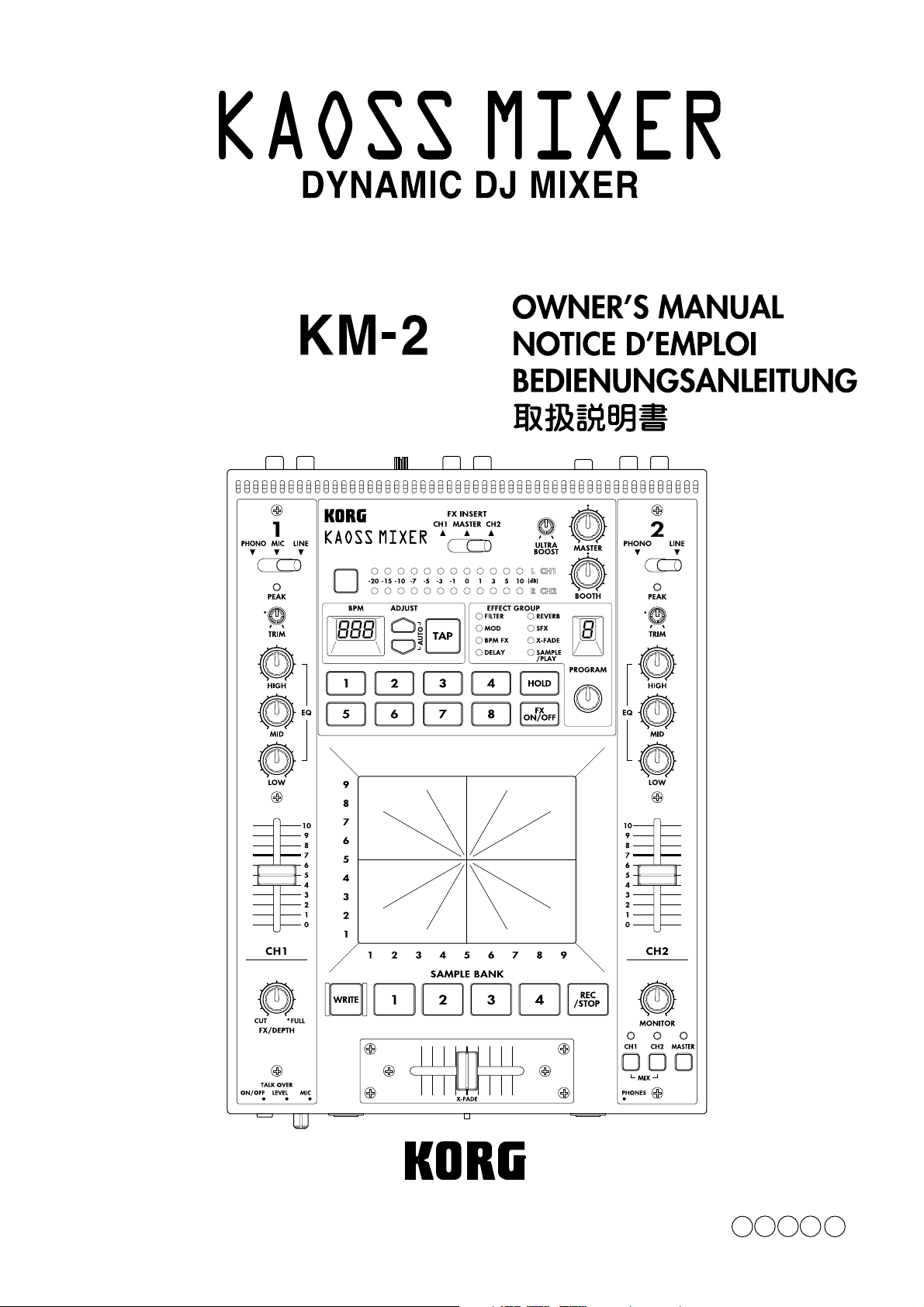
Page 1
E F G J 1
Page 2

Precautions
Location
Using the unit in the following locations can result in a malfunction.
• In direct sunlight
• Locations of extreme temperature or humidity
• Excessively dusty or dirty locations
• Locations of excessive vibration
Power supply
Please connect the designated AC/AC adaptor to an AC outlet of the correct voltage. Do not connect it to an AC outlet of voltage other than that
for which your unit is intended.
Interference with other electrical devices
This product contains a microcomputer. Radios and televisions placed nearby may experience reception interference. Operate this unit at a
suitable distance from radios and televisions.
Handling
To avoid breakage, do not apply excessive force to the switches or controls.
Care
If the exterior becomes dirty, wipe it with a clean, dry cloth. Do not use liquid cleaners such as benzene or thinner, or cleaning compounds or
flammable polishes.
Keep this manual
After reading this manual, please keep it for later reference.
Keeping foreign matter out of your equipment
• Never set any container with liquid in it near this equipment. If liquid gets into the equipment, it could cause a breakdown, fire, or electrical shock.
• Be careful not to let metal objects get into the equipment. If something does slip into the equipment, unplug the AC/AC adaptor from the wall
outlet. Then contact your nearest Korg dealer or the store where the equipment was purchased.
THE FCC REGULATION WARNING (for U.S.A)
This equipment has been tested and found to comply with the limits for a Class B digital device, pursuant to Part 15 of the FCC Rules. These
limits are designed to provide reasonable protection against harmful interference in a residential installation. This equipment generates, uses,
and can radiate radio frequency energy and, if not installed and used in accordance with the instructions, may cause harmful interference to
radio communications. However, there is no guarantee that interference will not occur in a particular installation. If this equipment does cause
harmful interference to radio or television reception, which can be determined by turning the equipment off and on, the user is encouraged to
try to correct the interference by one or more of the following measures:
• Reorient or relocate the receiving antenna.
• Increase the separation between the equipment and receiver.
• Connect the equipment into an outlet on a circuit different from that to which the receiver is connected.
• Consult the dealer or an experienced radio/TV technician for help.
Unauthorized changes or modification to this system can void the user’s authority to operate this equipment.
CE mark for European Harmonized Standards
CE mark which is attached to our company’s products of AC mains operated apparatus until December 31, 1996 means it conforms to EMC
Directive (89/336/EEC) and CE mark Directive (93/68/EEC). And, CE mark which is attached after January 1, 1997 means it conforms to EMC
Directive (89/336/EEC), CE mark Directive (93/68/EEC) and Low Voltage Directive (73/23/EEC).
Also, CE mark which is attached to our company’s products of Battery operated apparatus means it conforms to EMC Directive (89/336/EEC)
and CE mark Directive (93/68/EEC).
NOTICE
KORG products are manufactured under strict specifications and voltages required by each country. These products are warranted by the
KORG distributor only in each country. Any KORG product not sold with a warranty card or carrying a serial number disqualifies the
product from the manufacturer’s/distributor’s warranty and liability. This requirement is for your own protection and safety.
Page 3

GENERAL CONTENS
GENERAL CONTENS
OWNER’S MANUAL / ENGLISH ..........................................................................................2-8
NOTICE D’EMPLOI / FRANCAIS .........................................................................................1-8
BEDIENUNGSANLEITUNG / DEUTSCH.............................................................................1-8
/ JAPAN .............................................................................................................1-8
1
Page 4
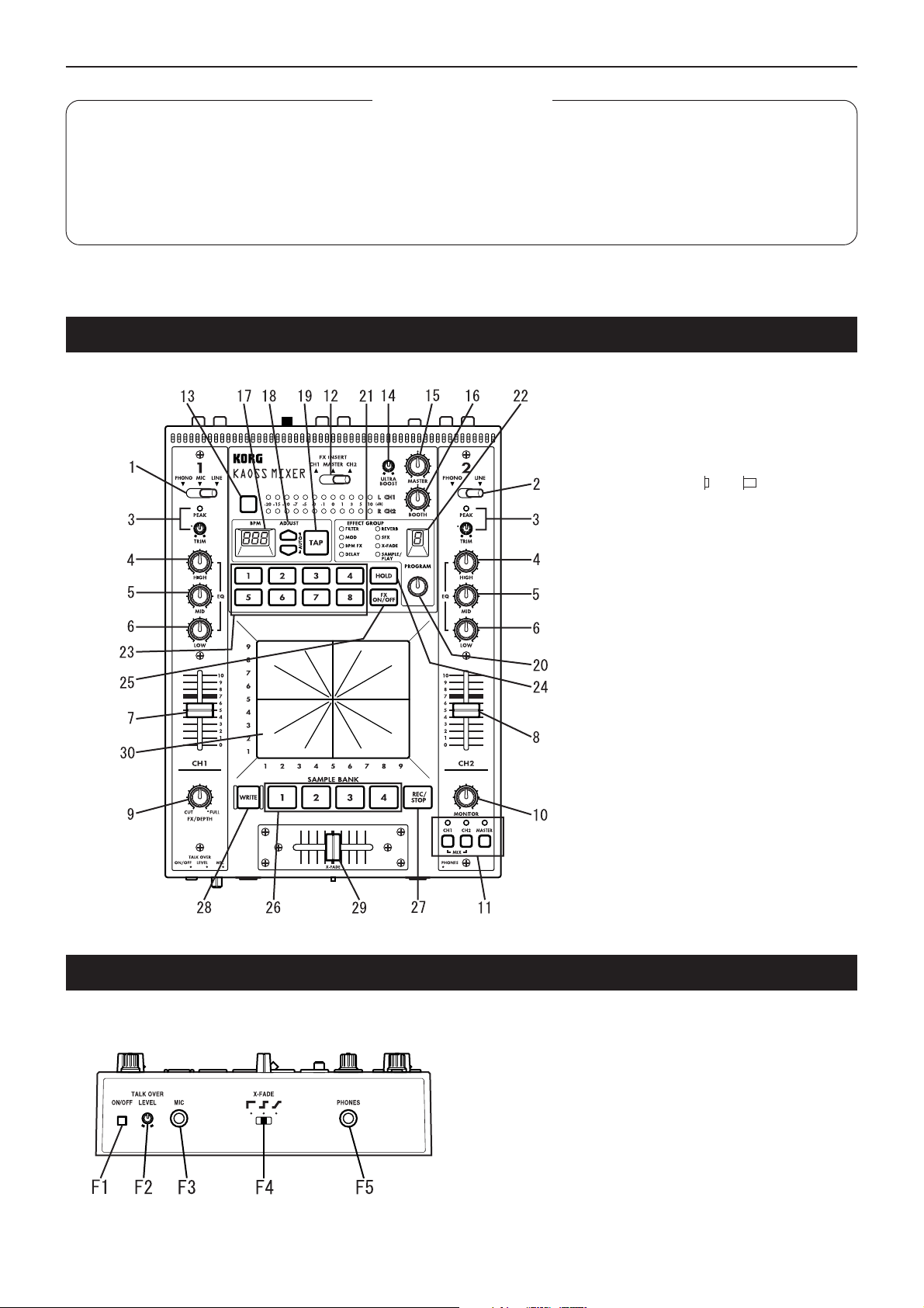
Contents / Connections and controls of the KM-2
Contents
Connections and controls of the KM-2 ....................................................................................2
Effect program list....................................................................................................................4
Operation .................................................................................................................................5
Calibrating the crossfader........................................................................................................7
Specifications...........................................................................................................................8
Connections and controls of the KM-2
Top panel
1. Channel 1 input select switch
Selects the input source for channel 1.
Note: If you wish to select the mic as the
input source, set the front panel TALK
OVER ON/OFF switch (F1) to the OFF
position.
LINE: CD player, etc. MIC: mic
PHONE: turntable
TALK OVER
:ON :OFF
2. Channel 2 input select switch
Selects the input source for channel 2.
3. PEAK (peak indicator), TRIM (trim knob)
Adjust the trim knob so that the peak indicator does not light even for high volume
levels.
4. HIGH EQ (high equalizer)
Adjusts the amount of boost/cut for the
high range equalizer.
5. MID EQ (middle equalizer)
Adjusts the amount of boost/cut for the mid
range equalizer.
6. LOW EQ (low equalizer)
Adjusts the amount of boost/cut for the low
range equalizer.
7. Channel 1 fader
Adjusts the volume of channel 1.
8. Channel 2 fader
Adjusts the volume of channel 2.
9. FX DEPTH (effect depth) knob
At the CUT position, no effect will be applied to the sound. At the FULL position,
the maximum effect will be applied to the
sound. Normally you will leave this in the
FULL position.
Front panel
F1. TALK OVER ON/OFF switch
When this switch is ON (pressed in), the audio from the mic input
will be mixed into the master output.
✩ If you are using the mic as the input for channel 1, set the TALK
OVER switch to OFF .
F2. MIC LEVEL knob
Adjusts the volume level of the mic.
F3. MIC input jack
Connect a mic to this jack.
Note: The mic input is an unbalanced input.
F4. X-FADE (cross fade curve switch)
Selects the curve of the cross-fader.
F5. PHONES (headphone) jack
2
Connect a set of headphones to this jack.
Page 5

Connections and controls of the KM-2
10. MONITOR knob
Adjusts the output level of the front panel
PHONES jack (F5).
11. Monitor select switch
CH1: Monitor the sound of channel 1.
CH2: Monitor the sound of channel 2.
MASTER: Monitor the sound that is being
sent to the master output.
MIX (press CH1 and CH2 simultaneously):
Monitor the sound of channel 1 in the L
channel of the headphones, and the sound
of channel 2 in the R channel.
12. FX INSERT (effect insert) switch
CH1: Insert the effect at the pre-fader location of channel 1.
CH2: Insert the effect at the pre-fader location of channel 2.
MASTER: Insert the effect at the master
(after the cross-fader) location.
✩ For some special effect programs, the
effect will be inserted at a different location. (Refer to p.4 "Effect program list.")
13. Level meter mode switch
Selects the display mode of the level meter.
Each time you press this switch, the following two display modes will be selected
alternately.
CH1/CH2: The meters will display the input levels of channels 1 and 2 (pre-fader)
respectively.
L/R: The meters will display the L channel
and R channel levels of the master output.
Use CH1/CH2 at a maximum of 0 dB~1 dB.
14. ULTRA BOOST knob
Adjusts the strength of the newly developed
Ultra Boost effect. Turning this knob toward
the right will increasingly boost the low frequency range and simultaneously emphasize the edge of the bass drum and bass
sounds.
15. MASTER volume
Adjusts the volume that is output from the
MASTER OUTPUT jacks (R6).
16. BOOTH volume
Adjusts the volume that is output from the
BOOTH OUTPUT jacks (R7).
17. BPM display
Displays the tempo of the song; i.e., the
BPM.
18. ADJUST (BPM adjust) keys
These keys make fine adjustments to the
BPM set by the TAP key (19) or by auto
BPM detection.
% increases the BPM value (makes the
tempo faster)
fi decrease the BPM value (makes the
tempo slower)
19. TAP key
When you tap this key twice or more in time
with the beat of the song, that beat will be
detected and the corresponding tempo displayed in the BPM display (17).
✩ The detectable range of BPM is 40~999.
✩ For details on the BPM function, refer to
p.5 "About the BPM function."
20. Effect program knob
Rotate this knob to select an effect program. Effect programs are organized into
eight groups such as FILTER or MOD
(modulation), and each group contains ten
programs, providing a total of 80 preset
programs.
21. Effect group display
This indicates the name of the currently selected effect program group.
22. Effect number display
This shows the currently selected effect
program number.
✩ For details on the effects provided by
each program, refer to p.4 "Effect program list."
23. Program map keys 1–8
Of the 80 effect programs, you can assign
eight of your favorite programs to the program map keys for immediate selection.
24. HOLD switch
While this switch is lit, the touch panel (30)
will be in the Hold state. In this state, the
previous state of the effect will be maintained even when you remove your finger
from the touch panel.
25. FX ON/OFF (effect on/off) switch
Each time you press this switch, it will alternate between lit (effect on) and dark (effect off).
26. SAMPLE BANK keys 1–4
Sampled phrases are stored in these keys.
If an effect program other than SAMPLE/
PLAY is selected, the stored phrase will
play back as long as you hold down the
corresponding key 1–4.
✩ The playback sound will be output to the
channel that is selected by the FX IN-
SERT switch (12).
✩ You can also use the touch panel to ap-
ply an effect to the playback.
27. REC/STOP (record) key
When a SAMPLE/PLAY effect program is
selected, recording will begin when you
press this key. Recording will end when you
press this key once again.
For details refer to p.6, "About the
SAMPLE/PLAY effects."
28. WRITE key
Newly sampled phrases will be lost when
the power is turned off. If you wish to keep
the phrases, you must write them into
memory. For details on the W rite procedure,
refer to p.7 "Saving your samples."
29. X-FADE (crossfader)
This sets the mixing ratio of channel 1 and
channel 2.
30. Touch panel
Use this to modify the sound of the effect.
Rear panel
R1.CH1 PHONO (channel 1 phono input jacks)
R2.CH2 PHONO (channel 2 phono input jacks)
Turntables can be connected to these jacks.
R3. CH1 LINE IN (channel 1 line input jacks)
R4. CH2 LINE IN (channel 2 line input jacks)
CD players etc. can be connected to these jacks.
R5.GND (ground) connector
Connect the GND (ground) connector of your turntable(s) to this
connector.
R6.MASTER OUTPUT jacks
These jacks output the volume adjusted by the MASTER volume (15).
R7.BOOTH OUTPUT jacks
These jacks output the volume adjusted by the BOOTH volume (16).
R8.~AC9V (power supply) connector
Connect the included power adaptor to this connector.
R9.POWER switch
✩ It will take up to 10 seconds after the power is turned on for the KM-
2 system to begin operating and be ready to use.
3
Page 6
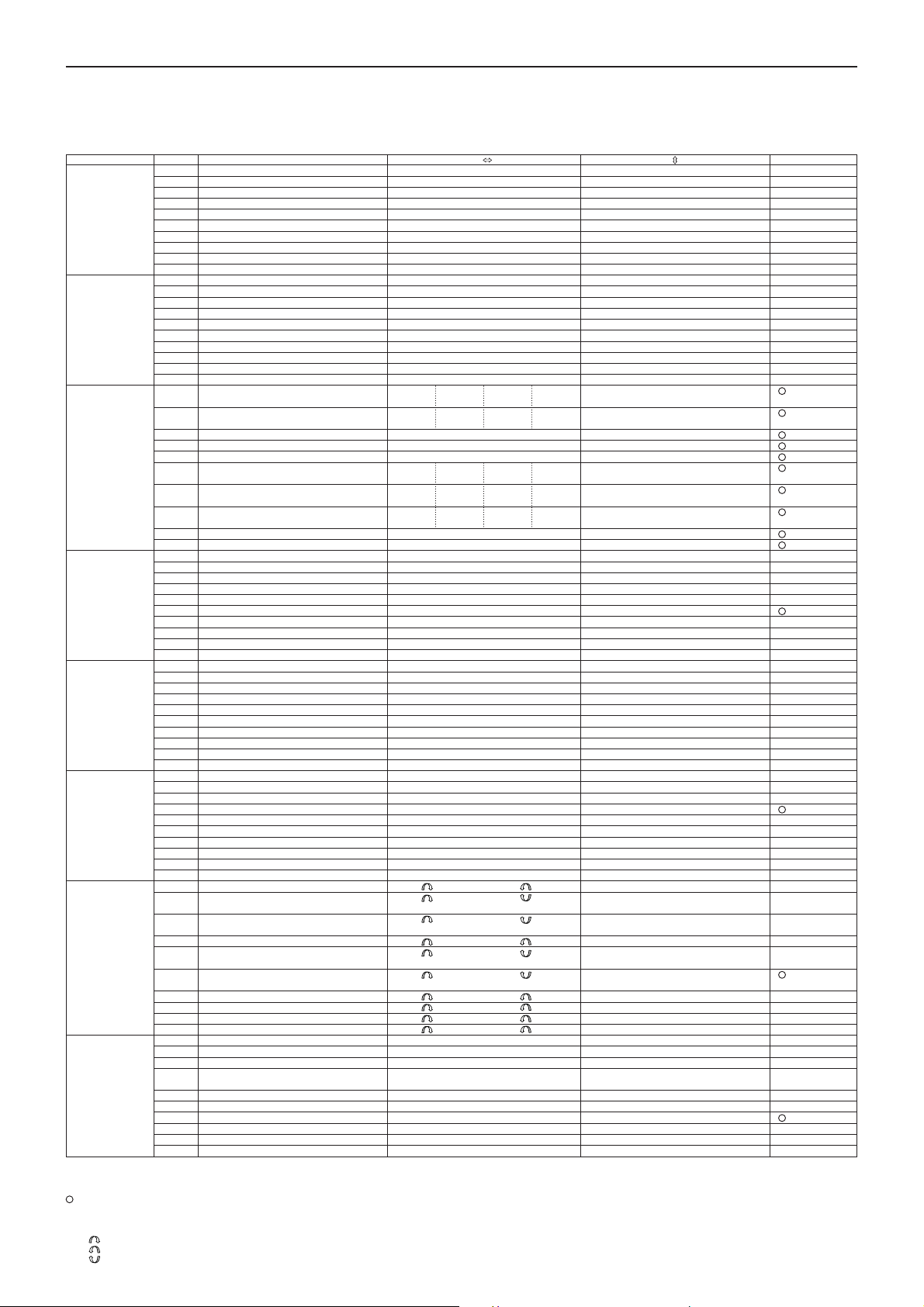
Effect program list
Effect program list
KM-2 EFFECT PROGRAM LIST
EFFECT GROUP PROG TITLE X Y BPM
FILTER 0 RESONANCE FILTER FREQUENCY RESONANCE
MODULATION 0 VIBRATE SPEED DEPTH
BPM FX 0 BPM DELAY1 X1-3 X3-5 X5-7 X7-9 FEEDBACK
DELEY 0 TAPE ECHO DELAY TIME FX LEVEL,FEEDBACK
REVERB 0 HALL REVERB TONE REVERB LEVEL
SFX 0 STEP MODULATION MOD DEPTH FX LEVEL
X-FADE 0 REVERB X-FADE1★ CH1 CH2 CH1 CH2 REV LEVEL
SAMPLE/PLAY 0 LOOP1(AUTO REC START) LOOP END TIME CONTROL PLAYBACK LEVEL
About programs marked by ★
Regardless of the FX INSERT location, the sample will be recorded from MASTER, and when monitoring CH1, CH2 or CH1&2 from the PHONES jack, the sound will be monitored without delay reverb
applied.
About AUTO REC START
When SAMPLE/PLAY number 0 is selected, recording will use AUTO REC START. After the REC key is pressed, recording will begin automatically when a signal is input.
For the X-FADE effect group and for DELAY-3, the effect will not be applied to the sample playback sound when the FX INSERT switch is set to MASTER.
Crossfade by moving across the touch panel from the center left edge toward the center right edge in a “hill” shape.
4
Crossfade by moving across the touch panel from the center right edge toward the center left edge in a “hill” shape.
Crossfade by moving across the touch panel from the center right edge toward the center left edge in a “U” shape.
1 ISOLATOR LPF/HPF TYPE HI CUT <-> LOW CUT NO ASSIGN
2 WAH FILTER SPEED DEPTH
3 DIST+VOICE FILTER TALKING DISTORTION
4 DIST+FILTER FREQUENCY DISTORTION
5 MANUAL PHASER FREQUENCY RESONANCE
6 PAN BY HPF X-FADE PAN FREQUENCY
7 DIST+ISOLATOR LOW-MID-HI DISTORTION
8 MID FREQ ISOLATOR MID BOOST<->CUT NO ASSIGN
9 3BAND ISOLATOR HI CUT <-> LOW CUT MID LEVEL
1 PHASER SPEED FREQUENCY
2 AUTO PAN LFO SPEED DEPTH
3 FLANGER+FILTER FLANGER SPEED FILTER FREQ
4 DIST+PHASER FREQUENCY FX LEVEL
5 MANUAL FLANGER1 DELAY TIME RESONANCE
6 MANUAL FLANGER2 DELAY TIME RESONANCE
7 PITCH SHIFT Lch PITCH Rch Pitch
8 TREMOLO SPEED DUTY
9 STEP PHASER MOD STEP RESONANCE
1 BPM DELAY2(TAPE ECHO TYPE ) X1-3 X3-5 X5-7 X7-9 FEEDBACK
2 BPM MULTI TAP DELAY1 NO ASSIGN LEVEL DELAY TIME
3 BPM MULTI TAP DELAY2 NO ASSIGN LEVEL DELAY TIME
4 BPM MULTI TAP DELAY3 NO ASSIGN FEEDBACK DELAY TIME
5 BPM PHASER X1-3 X3-5 X5-7 X7-9 RESONANCE
6 BPM FLANGER X1-3 X3-5 X5-7 X7-9 RESONANCE
7 BPM TREMOLO X1-3 X3-5 X5-7 X7-9 DEPTH
8 BPM STEP PHASER FREQUENCY(MANUAL) RESONANCE SPEED
9 BPM STEP FLANGER STEP SPEED RESONANCE SPEED
1 DELAY DELAY TIME FX LEVEL,FEEDBACK
2 DELAY DELAY TIME FX LEVEL,FEEDBACK
3 DELAY (POST FADER TYPE) ★ DELAY TIME DELAY LEV
4 MULTI TAP DELAY TONE FEEDBACK
5 LONG DELAY FEEDBACK FX LEVEL DELAY TIME
6 PING PONG DELAY DELAY TIME FEEDBACK
7 TALK MOD+DELAY TALKING DELAY LEVEL
8 FILTER +DELAY FILTER FREQ RESONANCE
9 DUB+DELAY DELAY TIME TONE
1 GATE REVERB1 TONE REVERB LEVEL
2 PLATE REVERB REV TIME REVERB LEVEL
3 GATE REVERB2 FREQUENCY REVERB LEVEL
4 REVERB+DELAY DELAY FEEDBACK REVERB LEVEL
5 REVERB+DELAY DELAY TIME REVERB LEVEL
6 TALK MOD+REVERB TALKING RESONANCE
7 FILTER+REVERB FILTER FREQ REVERB LEVEL
8 3D PAN L<->R PAN REVERB LEVEL
9 ROOM REVERB TONE REVERB LEVEL
1 RING MOD+FILTER RING FREQ FILTER FREQ
2 SIN WAVEFORM OSCLATOR PITCH OSC LEVEL
3 BPM DELAY + ISOLATOR ISOLATOR LOW-MID-HI DRY/WET BALANCE DELAY TIME
4 RING +DELAY TIME RING+DELAY BALANCE
5 TREMOLO+DELAY TIME + LFO SPEED DLY TREM X-FADE
6 SPECIAL ECHO TIME FX LEVEL
7 VOICE OSCLATOR PITCH CHARACTER
8 SQUARE WAVEFORM OSCLATOR PITCH OSC LEVEL
9 AQUA SPEED FX LEVEL
1 REVERB X-FADE2★ CH1 CH2 CH1 CH2 Y:5-9 CH1 REV LEVEL
2 ISOLATOR X-FADE★ CH1 CH2 CH1 CH2 Y:5-9 HI CUT (CH1), LOWCUT(CH2)
3 FILTER X-FADE2★ CH1 CH2 CH1 CH2 FILTER FREQ
4 RESONANCE FILTER X-FADE★ CH1 CH2 CH1 CH2 Y:5-9 LPF FREQ (CH1), LOWCUT(CH2)
5 BPM DELAY X-FADE★ CH1 CH2 CH1 CH2 Y:5-9 CH1 DLY LEVEL
6 PHASER X-FADE★ CH1 CH2 CH1 CH2 PHASING LEVEL
7 TAPE ECHO X-FADE★ CH1 CH2 CH1 CH2 DRY/WET BALANCE
8 FLANGER+REV X-FADE★ CH1 CH2 CH1 CH2 FLANGER+REV LEVEL
9 STEP MOD X-FADE★ CH1 CH2 CH1 CH2 STEP MOD LEVEL
1 FORWARD & REVERSE FORWARD & REVERSE PLAYBACK LEVEL
2 FORWARD & REVERSE(Hi SPEED) FORWARD & REVERSE PLAYBACK LEVEL
3 SCRATCHING SCRATCH Y:5-9:GATE ON
4 SCRATCHING WITH FILTER SCRATCH FILTER FREQ
5 TIME STRETCH SLOW <-> FAST TEMPO PLAYBACK LEVEL
6 SCRATCHING WITH BPM DELAY ★ SCRATCH DELAY LEVEL DELAY TIME
7 LOOP2 LOOP START TIME CONTROL PLAYBACK LEVEL
8 FORWARD & REVERSE with DELAY FORWARD & REVERSE DELAY LEVEL
9 FORWARD&REVERSE with SFX FORWARD & REVERSE SFX CONTROL
1/4BEAT 1/2 BEAT 1/3 BEAT 3/4 BEAT
1/4BEAT 1/2 BEAT 1/3 BEAT 3/4 BEAT
x2BEAT x1 BEAT 1/2 BEAT 1/4 BEAT
x2BEAT x1 BEAT 1/2 BEAT 1/4 BEAT
x1BEAT 1/2 BEAT 1/4 BEAT 1/8 BEAT
Y:1-5 CH2 REV LEVEL
Y:1-5 LOW CUT (CH1), HI CUT(CH2)
Y:1-5 LOW CUT (CH1), LPF FREQ(CH2)
Y:1-5 CH2 DLY LEVEL
Y1-5:GATE OFF
DELAY TIME
DELAY TIME
SPEED
SPEED
SPEED
DELAY TIME
Page 7
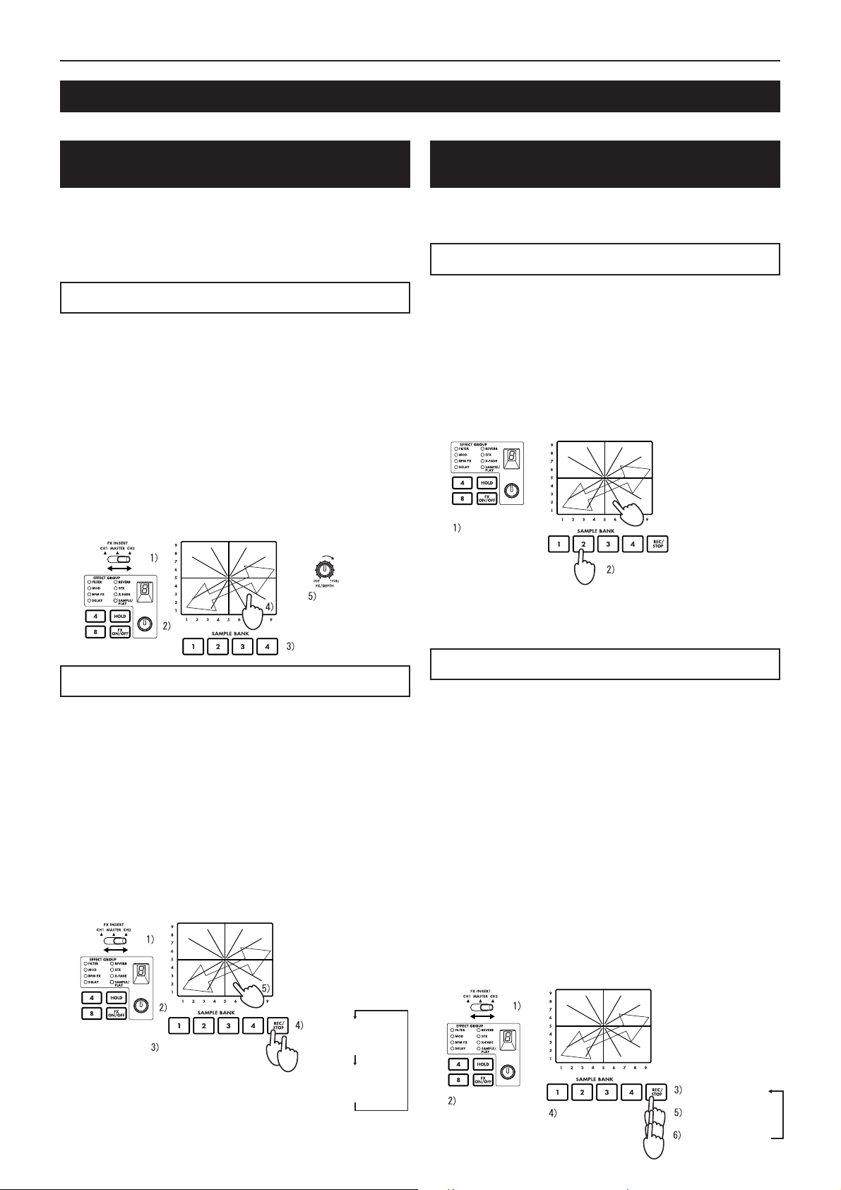
Operation
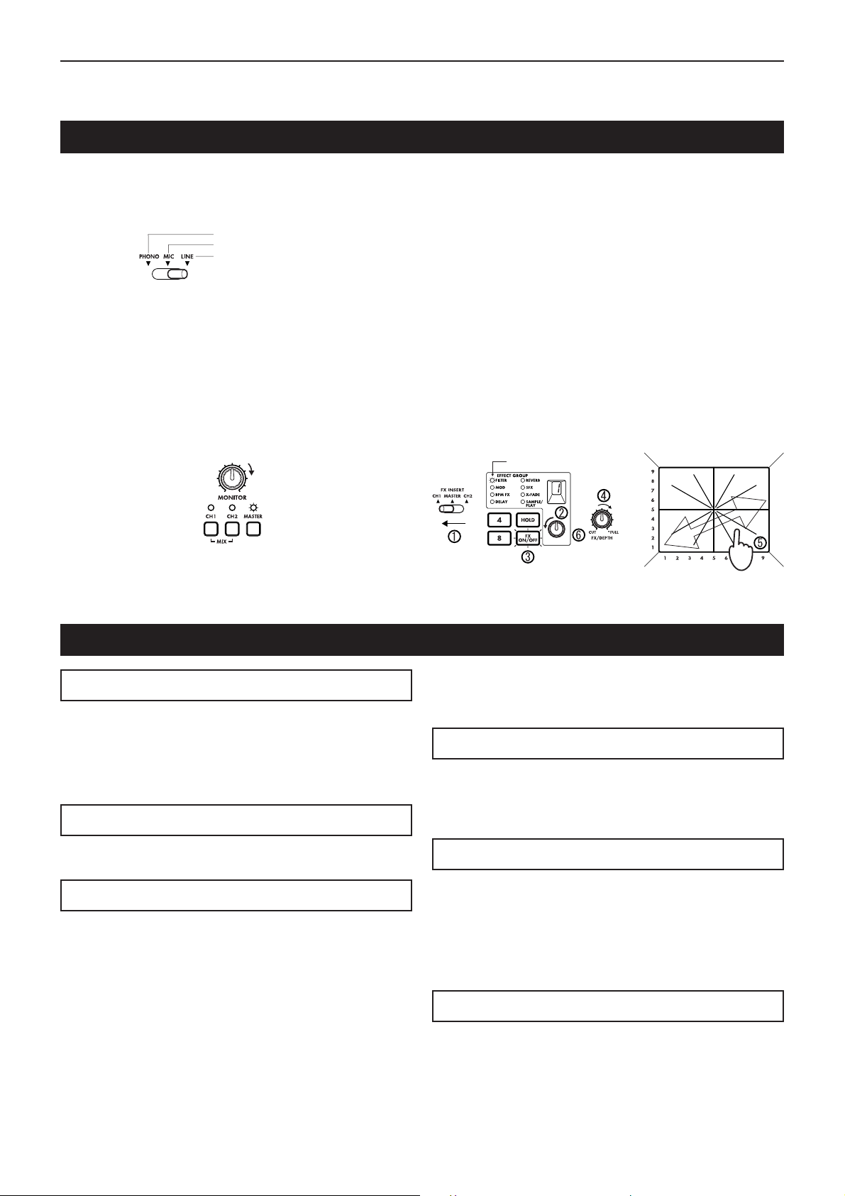
Basic operation
Operation
1) As described in "Connections and controls of the KM-2"
(p.2), connect your turntable(s) or CD player(s) to CH1 and
CH2. Set the input select switches (1, 2) to the appropriate
position for the devices that are connected to channels 1
and 2.
For turntable input
For MIC input
For CD etc.
2) If you are using headphones for listening, connect your
headphones to the front panel PHONES jack (F5).
In this explanation we will assume that you are monitoring
through headphones.
3) Turn on the POWER switch (R9). It will take up to 10 seconds for the KM-2 system to begin operating and be ready
to use. The system has finished starting up when the BPM
display stops rotating.
4) Make sure that the monitor select switches (11) are set to
MASTER, and use the MONITOR knob (10) to adjust the
volume of the headphones.
Adjust the volume
Lit
5) Here's how to monitor the sound of CH1 in the headphones.
Set the CH1 fader (7) to approximately 50~70%. If the PEAK
LED lights, the input is too loud. Rotate the TRIM knob (3)
toward the left until the LED no longer lights. At this time,
set X-FADE (29) to the CH1 (left) position.
6) Use the touch panel (30) to control the effect.
The effect section of the KM-2 lets you control the sound by
moving across the X-axis (horizontal) and Y-axis (vertical)
of the touch panel. For details on which effect is in what
number, and the parameters that are controlled by the Xaxis and Y-axis, refer to p.4 "Effect program list."
Here's how to apply an effect to the CH1 signal.
1 Set FX INSERT (12) to CH1.
2 For this example, rotate the effect program knob (20) to
select program number 1 of the FIL TER group.
3 Make sure that the FX ON/OFF switch (25) is lit.
4 Rotate the FX DEPTH knob (9) all the way to the right.
5 Touch the touch panel (30), and the effect will be applied.
6 Rotate the effect program knob (20) to change the program.
Lit
Rotate all
the way
About the BPM function
What is BPM?
BPM stands for Beats Per Minute, and indicates the tempo of
the song in terms of the number of beats (quarter notes) that
occur in one minute.
If BPM=120, there will be 120 beats in one minute of the song,
meaning that each beat is 0.5 seconds long. Higher BPM values mean that the tempo is faster.
Detecting the BPM
There are two ways to set the BPM: auto BPM detection, or
BPM tap input.
Auto BPM
1) Use the FX INSERT switch (12) to select the channel (CH1
or CH2) into which you are inputting the song whose BPM
you wish to detect.
2) Simultaneously press the ADJUST % and fi keys (18). This
will cause the BPM to be detected automatically and displayed in the BPM indicator (17).
3) Press % or fi to end detection and finalize the BPM.
✩ If you operate the FX INSERT switch (12) or press % and fi
simultaneously while auto BPM detection is occuring, auto
BPM detection will be cancelled.
✩ Auto BPM detection will not function if the FX INSERT (12)
is set to MASTER.
✩ It may not be possible to correctly detect the BPM of songs
with complex drum phrases. In such cases, use TAP to input the BPM.
✩ The AUTO BPM detection range is 80–160.
Using TAP to input the BPM
Press the TAP key (19) twice or more in time with the beat of
the song. When you do so, that tempo will be displayed in the
BPM indicator (17).
✩ BPM input via TAP can be performed even if the FX IN-
SERT switch (12) is set to MASTER.
Fine adjustment of BPM
After the BPM has been detected or set, you can use the ADJUST
% fi switches (18) to make fine adjustments to the BPM setting.
✩ When you switch the setting of the FX INSERT switch (12),
the previous BPM detection value for that channel will be
displayed.
✩ When performing BPM detection for the first time, the de-
fault value will be BPM=120.
BPM effects
If an effect program of the BPM FX group is selected, you can apply
an effect that is synchronized to the BPM.
For example with the BPM FX-1 program BPM DELA Y2, touching the
touch panel (30) in the 3–5 area of the horizontal axis will cause the
delay length to be half of the BPM. For details on other BPM effects,
refer to p.4 “Effect program list.”
✩ If you use the TA P key (19) to input the BPM, the BPM
value will be applied to the effect immediately.
✩ If you use auto BPM, the BPM value will be applied to the
effect when you press ADJUST (18) % or fi.
5
Page 8
Operation
About the SAMPLE/PLAY effects
The sampling function of the KM-2 lets you store four different six-second samples.
Recording and playback when a
SAMPLE/PLAY effect program is selected
You can record or play back samples when a SAMPLE/PLAY
effect program is selected. Playback speed and reverse-playback etc. can be controlled from the touch panel.
✩ Playback control will differ depending on the effect program.
Refer to p.4 "Effect program list."
Playback procedure
1) Use the FX INSERT switch (12) to select the channel into
which the playback sound will be mixed.
2) Select a program of the SAMPLE/PLAY group.
3) Use the SAMPLE BANK keys 1–4 (26) to select the sample
that you wish to play back. (At this time the sample will not
play yet.)
4) When you press the touch panel (30), playback will occur
according to the location you touched.
5) You can use the FX DEPTH knob (9) to adjust the volume
of the playback. When the knob is in the center position,
the sample playback sound will be added to the channel
input sound in a 1:1 ratio. When the knob is at the maximum position, only the sample will be heard during playback, and the channel input sound will not be heard.
Playback
from touch
panel
Playback volume
(select)
Recording procedure
1) Use the FX INSERT switch (12) to select whether to record
the sound of CH1, CH2, or MASTER.
2) Use the effect program knob (20) to select a SAMPLE/PLAY
program.
For this example, select SAMPLE/PLA Y-1.
3) Use the SAMPLE BANK keys 1–4 (26) to select the sample
bank 1–4 into which you will record.
4) Press the REC/STOP key (27) to start recording. Recording will end when you press the REC/STOP key once again
(or when the maximum recording time has elapsed).
✩ During recording, the REC/STOP key (27) LED will light.
5) Press the touch panel (30), and the recorded phrase will
play. The way in which the phrase plays will differ depending on the program. Refer to p.4 "Effect program list."
Playback
from touch
panel
Recording and playback when a nonSAMPLE/PLAY effect program is selected
You can record and play back phrases (basic playback) even
when a non-SAMPLE/PLAY effect program is selected.
Playback and recording is not possible when FX is off.
Playback procedure
1) Use the effect program knob (20) to select an effect program from other than the SAMPLE/PLA Y group.
2) When you press a SAMPLE BANK key 1–4 (26), the corresponding sample will play back as long as you continue
holding that key. However, the sample will play at normal
speed, and will loop (play repeatedly) at the volume at which
it was recorded.
✩ By operating the touch panel (30) while you play the sample,
you can apply an effect to the sample playback.
✩ The playback sound will be mixed into the channel that is
selected by the FX INSERT switch (12).
You can apply an
effect to the playback
sound
Select other
than SAMPLE/
PLAY
Play only while pressed
✩ If you press the HOLD switch (24) during playback, the play-
back will be held.
When you press a SAMPLE BANK key 1–4 (26) once again,
hold will be defeated.
Recording procedure
1) Use the FX INSERT switch (12) to select whether to record
the sound of CH1, CH2, or MASTER.
2) Use the effect program knob (20) to select a non-SAMPLE/
PLAY program.
3) Press the REC/STOP key (27) to enter record-ready mode. (Y ou
can cancel this state by pressing the FX ON/OFF switch (25).)
✩ The REC/STOP key (27) LED will blink to indicate that you
are in record-ready mode.
4) Use the SAMPLE BANK keys 1–4 (26) to select the sample
bank 1–4 into which the sample will be stored. (The sample
sound will not be heard at this time.)
5) Press the REC/STOP key (27) once again to begin recording.
6) Recording will stop when you press the REC/STOP key (27)
once again (or when the maximum recording time has
elapsed).
✩ During recording, the REC/STOP key (27) LED will light.
✩ If you wish to re-record, repeat the procedure from step 3.
✩ If you record using a non-SAMPLE/PLAY program, the ef-
fect sound as controlled by the touch panel will also be recorded.
1st time:
Select the BANK
to record
6
Start recording
(LED lit)
2nd time:
Stop recording
(LED dark)
Select other
than SAMPLE/
PLAY
Select the
BANK to
record
Record-ready
(LED blinking)
Start recording
(LED lit)
Stop recording
(LED dark)
Page 9

Operation/Calibrating the crossfader
Saving a sample - "WRITE"
Phrases that you record using the REC/STOP key are only
written temporarily into the internal memory of the KM-2, and
will be lost when the power is turned off. If you wish to keep
them, you must perform the WRITE operation. Conversely,
phrases you have already saved using WRITE will not be erased
by additional recording as long as you do not perform the WRITE
operation again.
1) Press and hold the WRITE key (28) for two seconds. The WRITE
LED will begin blinking, and the KM-2 will be in write-ready mode.
2) Press the SAMPLE BANK key(s) 1–4 (26) that you wish to
save. (The SAMPLE BANK you pressed will blink.) Y ou may
select two or more banks to write.
✩ If you press the TAP key (19) or the FX ON/OFF switch (25)
at this point, the WRITE operation will be cancelled.
3) Press the WRITE key (28) once again, and writing will begin. Writing will require a maximum of 20 seconds per bank.
While writing is being performed, the level meter will indicate the progress. When writing is completed, the WRITE
key (28) LED will go dark.
✩ Never turn off the power during the writing process. Doing
so will cause the data to be lost.
About the program map keys
Y our favorite ef fect programs can be assigned to the program MAP 1–8 keys for quick access. The program map keys store not
only the effect program number, but also the HOLD ON/OFF status, the HOLD position, and other data listed below.
Data stored in a program MAP
• Effect program group number
• HOLD ON/OFF status and location (coordinates)
• For the BPM FX group, the BPM value that was displayed
when you stored the MAP
• For the SAMPLE/PLAY group, the SAMPLE BANK number
used (the SAMPLE BANK 1–4 that was selected when you
stored the memory will be remembered)
1) Press the MAP number 1–8 (23) in which you wish to store.
2) Use the effect program knob (20) to select the effect program that you wish to store.
If you wish to store with HOLD ON, select the HOLD ON
(LED lit) state, and touch the touch panel (30) at the desired coordinates.
3) Press and hold the currently-lit program map key (23) for
two seconds. When the MAP LED has blinked three times,
the data has been stored.
• At this time, the value in the effect number display will also blink.
Storing to a MAP memory
Calibrating the crossfader
On the KM-2 you can adjust the point at which CH 1 and CH 2 of the crossfader begin to change.
(With the factory settings, the change will begin with minimal movement.)
1) Turn the power off.
2) While holding down the WRITE key (28) and the REC/STOP key (27), turn the power on.
When you do so, the BPM display will show “CAL,” indicating that you are in Calibration mode.
3) Now if you move the crossfader (29), the LEDs of SAMPLE BANK keys 1–4 (26) will light accordingly.
The point at which the light changes from 1 → 2 is the point at which the crossfader currently starts changing from CH 1 to CH 2.
The point at which the light changes from 4 → 3 is the point at which the crossfader currently starts changing from CH 2 to CH 1.
4) First, move the crossfader to the location at which you want begin changing from CH 1 → CH 2.
5) When you press the REC/STOP key (27), the switching point will be updated.
6) Repeat steps 4 and 5 to set the CH 2 → CH 1 point.
7) When you press the WRITE key (28), the data for the specified points will be stored in internal memory, and you will return to
normal operating mode.
✩ The switching points cannot be set to a location where BANK LED 2 and 3 are lit simultaneously.
✩ The minimum switching point is approximately 3.0 mm from the left or the right. It is not possible to set the switching point
closer to the left or right edge.
(If you perform step 5 with the crossfader moved all the way to left or right, the switching point will automatically be set to the
minimum location.)
✩ The calibration data is preserved even when the power is turned off.
7
Page 10

Specifications
Specifications
Input section
BPM : 40~999 (TAP)
80~160 (AUTO)
PHONE INPUT : input impedance 40 k-ohms, reference
level -40 dBu
LINE INPUT : input impedance 10 k-ohms, reference
level -10 dBu
MIC INPUT : input impedance 9 k-ohms, reference
level -40 dBu
MASTER OUTPUT : output impedance 600 ohms, reference
level 0 dBu
MONITOR OUTPUT : output impedance 33 ohms
Effect section
Sampling frequency : 44.1 kHz
AD/DA : 20 bit
Maximum recording time : 23.7 seconds
Effect programs : 80
Program maps : 8
Power consumption : 12.3 W (TYP)
Dimensions : W ✕ D ✕ H = 218 mm ✕ 206 mm ✕ 90
mm (including protrusions)
Weight : 1.8 kg
Included items : Power supply adaptor
: Touch panel protection sheet
Options : Cross fader unit
8
Page 11

Table des matières / Précautions à prendre
Table des matières
Précautions à prendre .............................................................................................................1
Connecteurs et commandes du KM-2 .....................................................................................2
Liste des programmes d'effets.................................................................................................4
Fonctionnement .......................................................................................................................5
Calibrage du cross fader .........................................................................................................7
Spécifications techniques ........................................................................................................8
Précautions à prendre
Emplacement
L’utilisation de l’appareil dans les endroits suivants risquerait d’être la cause d’un mauvais fonctionnement:
• Sous les rayons directs du soleil
• Dans des endroits de températures extrêmes ou d’une humidit é excessive.
• Dans des endroits excessivement sales ou poussiéreux.
• Dans des lieux sujets à des vibrations excessives.
Alimentation
Veuillez raccorder l’adaptateur secteur fourni à une prise de courant fournissant la tension adéquate. Ne jamais le raccorder à une prise d’un
autre voltage que celui prévu pour l’appareil.
Interférences avec d’autres appareils électriques
Cet instrument contient un micro-ordinateur. Les postes de radio et de télévision situés à proximité peuvent par conséquent souffrir d’interférences à la réception. Veuillez dès lors faire fonctionner cet appareil à une distance raisonnable de postes de radio et de télévision.
Manipulations
Pour éviter tout dommage, ne jamais exercer une force excessive sur les interrupteurs ou les commandes.
Entretien
Essuyer l’extérieur avec un chiffon propre et sec. Ne jamais utiliser de détergents liquides comme du benzène ou du thinner ni des composants
de nettoyage ou des cires inflammables.
Conserver le manuel
Après avoir lu attentivement le présent manuel, veuillez le conserver pour pouvoir le consulter ultérieurement.
Tenir tout corps étranger à l’écart de l’instrument:
• Ne jamais poser de récipient contenant du liquide à proximité de l’instrument. La pénétration de liquide dans l’instrument risquerait de
provoquer une panne, un incendie ou un court-circuit.
• Veiller à ce qu’aucun objet métallique ne tombe dans l’instrument. Si un corps étranger a pénétré dans l’équipement, débrancher l’adaptateur
de la prise secteur puis contacter le représentant Korg le plus proche ou le magasin oú l’équipement a été acheté.
La marque CE attachée à nos produits alimentés par secteur indique que ces produits sont conformes à la directive EMC (89/336/CEE) ainsi
* Marque CE de conformité aux normes de sécurité européennes
qu' à la directive relative à la marque CE (93/68/CEE).Cette marque est valable jusqu'au 31 décembre 1996.
La marque CE attachée après le 1 janvier 1997 indique que ces produits sont conformes à la directive EMC (89/336/CEE), à la directive
relative à la marque CE (93/68/CEE) ainsi qu'à la directive relative au courant de guitare tension (73/23/CEE).
Enfin, la marque CE attachée à nos produits alimentés par batterie indique que ces produits sont conformes à la directive EMC (89/336/CEE)
ainsi qu' à la directive relative à la marque CE (93/68/EEC).
ATTENTION
Les produits KORG sont fabriqués suivant les normes et les tentions d’alimentation requises dans chaque pays. Ces produits sont garantis
par le distributeur KORG dans le cadre de sa seule distribution. Tout produit KORG non vendu avec sa carte de garantie ou ne portant pas
son numéro de série perd le bénéfice de la garantie du fabricant. Ces dispositions ont pout but la protection et la sécurité de l’utilisateur.
1
Page 12

Connecteurs et commandes du KM-2
Connecteurs et commandes du KM-2
Panneau supérieur
1. Sélecteur d'entrée du canal 1
Sélectionne la source d'entrée pour le
canal 1.
Remarque: Pour sélectionner le micro
comme source d'entrée, régler le commutateur TALK OVER ON/OFF (F1) de la
face avant sur la position OFF.
LINE: Lecteur CD, etc. MIC: Micro
PHONE: Tourne-disque
TALK OVER
2. Sélecteur d'entrée du canal 2
Sélectionne la source d'entrée pour le
canal 2.
3. PEAK (indicateur de pointe), TRIM (bouton de sensibilité)
Réglez le bouton de sensibilité de sorte
que l'indicateur de pointe ne s'allume pas,
même à des volumes élevés.
4. HIGH EQ (égaliseur hautes fréquences)
Règle l'importance de la stimulation/coupure pour l'égaliseur des hautes fréquences.
:ON :OFF
Face avant
F1. Commutateur TALK OVER ON/OFF
Lorsque ce commutateur est sur ON (enfoncé), les parties audio
de l'entrée du micro sont mélangées à la sortie principale.
✩ Si vous utilisez le micro comme entrée pour le canal 1, réglez
F2. Bouton MIC LEVEL
Règle le volume du micro.
5. MID EQ (égaliseur moyennes fréquences)
Règle l'importance de la stimulation/coupure pour l'égaliseur des moyennes fréquences.
6. LOW EQ (égaliseur basses fréquences)
Règle l'importance de la stimulation/coupure pour l'égaliseur des basses fréquences.
7. Atténuateur (fader) du canal 1
Règle le volume du canal 1.
8. Atténuateur (fader) du canal 2
Règle le volume du canal 2.
9. Bouton FX DEPTH (intensité de l'effet)
Sur la position de coupure CUT, aucun
effet n'est appliqué au son. Sur la position FULL, l'effet maximum est appliqué.
Normalement, ce bouton se met sur la
position FULL.
le commutateur TALK OVER sur OFF.
F3. Prise d'entrée MIC
Sert à brancher un micro.
Remarque: L'entrée micro est une entrée non équilibrée.
F4. X-FADE (commutateur de courbe du cross fade)
Sélectionne la courbe du cross fade.
F5. Prise PHONES (casque d'écoute)
Sert à brancher un casque d'écoute.
2
Page 13

Connecteurs et commandes du KM-2
10. Bouton MONITOR
Règle le niveau de sortie de la prise PHO-
NES (F5) de la face avant.
11. Sélecteur de surveillance
CH1: Surveille le son du canal 1.
CH2: Surveille le son du canal 2.
MASTER: Surveille le son envoyé à la sor-
tie principale.
MIX (appuyez simultanément sur CH1 et
CH2): Surveille le son du canal 1 sur le
canal L (gauche) du casque d'écoute et le
son du canal 2 sur le canal R (droit).
12. Interrupteur FX INSERT (insertion d'effet)
CH1: Insère l'effet à un emplacement préatténuateur du canal 1.
CH2: Insère l'effet à un emplacement préatténuateur du canal 2.
MASTER: Insère l'effet à l'emplacement
principal (après le cross fader).
✩ Dans certains programmes d'effets spé-
ciaux, l'effet est inséré à un emplacement différent. (Voir p.4 "Liste des programmes d'effets.")
13. Sélecteur de mode pour le compteur de
niveau
Sélectionne le mode d'affichage du compteur de niveau. A chaque pression du sélecteur, les deux modes d'affichage suivants sont sélectionnés alternativement.
CH1/CH2: Les compteurs affichent respectivement les niveaux d'entrée des canaux
1 et 2 (pré-atténuateur).
L/R: Les compteurs affichent les niveaux
des canaux L et R de la sortie principale.
Utiliser CH.1/CH.2 à un maximum de 0 dB
~ 1 dB
14. Bouton ULTRA BOOST
Règle l'intensité du nouvel effet Ultra Boost.
Tournez ce bouton vers le droite pour stimuler chaque fois davantage la plage des
basses fréquences et accentuer simultanément les seuils des sons de grosse
caisse et de basses.
15. Volume MASTER
Règle le volume diffusé par les prises
MASTER OUTPUT (R6).
16. Volume BOOTH
Règle le volume diffusé par les prises
BOOTH OUTPUT (R7).
17. Affichage BPM
Affiche le tempo du morceau, notamment
les BPM.
18. Touches ADJUST (réglage des BPM)
Ces touches permettent d'effectuer des
réglages précis aux BPM définis par la touche TAP (19) ou par la détection automatique des BPM.
% augmente la valeur des BPM (accélère
le tempo)
fi diminue la valeur des BPM (ralentit le
tempo)
19. Touche TA P
Lorsque vous frappez cette touche deux
fois ou plus au rythme du tempo du morceau, l'appareil détecte le tempo et celuici apparaît sur l'affichage BPM (17).
✩ La plage de détection des BPM s'étend
de 40 à 999.
✩ Pour plus de détails concernant la fonc-
tion BPM, se reporter à la p.5 "A propos
de la fonction BPM."
20. Bouton des programmes d'effets
Tournez ce bouton pour sélectionner un
programme d'effets. Les programmes d'effets sont répartis en huit groupes comme
FILTER ou MOD
(modulation) et chaque groupe comprend
dix programmes, ce qui donne un total de
80 programmes de présélections.
21. Affichage du groupe d'effets
Indique le nom du groupe de programmes
d'effets sélectionné.
22. Affichage du numéro d'effet
Montre le numéro du programme d'effets
sélectionné.
✩ Pour plus de détails sur les effets de
chaque programme, voir p.4 "Liste des
programmes d'effets."
23. Touches de cartes de programmes 1 à 8
Parmi les 80 programmes d'effets disponibles, huit de vos programmes favoris peuvent être affectés aux touches de cartes
de programmes pour leur sélection immédiate.
24. Interrupteur HOLD
Lorsque cet interrupteur est allumé, le panneau sensible au toucher (30) se trouve
dans la condition de maintien. Dans ce cas,
l'état de l'effet est conservé même si vous
retirez votre doigt du panneau sensible au
toucher.
25. Interrupteur FX ON/OFF (effet activé/dé-
sactivé)
Chaque fois que vous appuyez sur cet interrupteur sa condition alterne entre allumé
(effet activé) et éteint (effet désactivé).
26. Touches SAMPLE BANK 1–4
Servent à mémoriser les phrases échantillonnées. Si un programme d'effets autre
que SAMPLE/PLAY est sélectionné, la
phrase mémorisée se reproduit aussi longtemps que vous maintenez la touche 1–4
correspondante enfoncée.
✩ Le son de reproduction sera diffusé par
le canal sélectionné à l'aide de l'interrupteur FX INSERT (12).
✩ Vous pouvez également utiliser le pan-
neau sensible au toucher pour ajouter
un effet à la reproduction.
27. Touche REC/STOP (enregistrement)
Lors de la sélection d'un programme d'effets SAMPLE/PLAY, l'enregistrement démarre dès que vous appuyez sur cette touche et il se termine lorsque vous réappuyez
sur la touche.
Pour plus de détails, voir p.6, "A propos
des effets SAMPLE/PLAY."
28. Touche WRITE
Les nouvelles phrases échantillonnées
sont perdues à la mise hors tension. Pour
éviter cela, vous devez les mémoriser. Pour
plus de détails sur la procédure de sauvegarde (d'écriture) voir p.7 "Sauvegarde des
échantillons."
29. X-FADE (crossfader)
Cette fonction permet de définir le taux de
mélange du canal 1 et du canal 2.
30. Panneau sensible au toucher
Sert à modifier le son de l'effet.
Panneau arrière
R1.CH1 PHONO (prises d'entrée pour tourne-disque du canal 1)
R2.CH2 PHONO (prises d'entrée pour tourne-disque du canal 2)
Permettent de raccorder un tourne-disque.
R3. CH1 LINE IN (prises d'entrée de ligne du canal 1)
R4. CH2 LINE IN (prises d'entrée de ligne du canal 2)
Permettent de raccorder des lecteurs CD, etc.
R5.Connecteur GND (terre)
Raccorder cette borne à la borne GND (terre) de votre ou de vos
tourne-disques.
R6.Prises MASTER OUTPUT
Ces prises diffusent le volume défini par la commande de volume
MASTER (15).
R7.Prises BOOTH OUTPUT
Ces prises diffusent le volume défini par la commande de volume
BOOTH (16).
R8.Connecteur ~AC9V (alimentation)
Raccorder ce connecteur à l'adaptateur secteur fourni.
R9. Interrupteur POWER
✩ Attendre jusqu’à 10 secondes après la mise sous tension pour
que le KM-2 se mette à fonctionner et soit prêt à être utilisé.
3
Page 14

Liste des programmes d'effets
Liste des programmes d'effets
KM-2 EFFECT PROGRAM LIST
EFFECT GROUP PROG TITLE X Y BPM
FILTER 0 RESONANCE FILTER FREQUENCY RESONANCE
MODULATION 0 VIBRATE SPEED DEPTH
BPM FX 0 BPM DELAY1 X1-3 X3-5 X5-7 X7-9 FEEDBACK
DELEY 0 TAPE ECHO DELAY TIME FX LEVEL,FEEDBACK
REVERB 0 HALL REVERB TONE REVERB LEVEL
SFX 0 STEP MODULATION MOD DEPTH FX LEVEL
X-FADE 0 REVERB X-FADE1★ CH1 CH2 CH1 CH2 REV LEVEL
SAMPLE/PLAY 0 LOOP1(AUTO REC START) LOOP END TIME CONTROL PLAYBACK LEVEL
A propos des programmes marqués d’un ★
Quel que soit l’emplacement d’insertion de l’effet FX INSERT, l’échantillon est enregistré à partir du MASTER et, lors de la surveillance de CH1, CH2 ou CH1&2 à partir de la prise du casque d’écoute
PHONES, le son est contrôlé sans application de réverbération de retard (DELAY REVERB).
A propos de la fonction de démarrage automatique de l’enregistrement AUTO REC START
Lorsque le numéro 0 est sélectionné pour SAMPLE/PLAY, l’enregistrement fait appel à la fonction AUTO REC START. Ainsi, lorsque vous appuyez sur la touche d’enregistrement REC, l’enregistrement commence automatiquement dès l’entrée d’un signal.
Dans le groupe d’effets X-FADE et dans DELAY-3, l’effet ne s’appliquera pas au son de la reproduction de l’échantillon si le commutateur FX INSERT est en position MASTER.
4
Cross fade en forme de “montagne lorsqu’on se déplace sur le panneau sensible au toucher du centre du bord gauche au centre du bord droit”.
Cross fade en forme de “montagne lorsqu’on se déplace sur le panneau sensible au toucher du centre du bord droit au centre du bord gauche”.
Cross fade en forme de “U” lorsqu’on se déplace sur le panneau sensible au toucher du centre bord du droit au centre du bord gauche.
1 ISOLATOR LPF/HPF TYPE HI CUT <-> LOW CUT NO ASSIGN
2 WAH FILTER SPEED DEPTH
3 DIST+VOICE FILTER TALKING DISTORTION
4 DIST+FILTER FREQUENCY DISTORTION
5 MANUAL PHASER FREQUENCY RESONANCE
6 PAN BY HPF X-FADE PAN FREQUENCY
7 DIST+ISOLATOR LOW-MID-HI DISTORTION
8 MID FREQ ISOLATOR MID BOOST<->CUT NO ASSIGN
9 3BAND ISOLATOR HI CUT <-> LOW CUT MID LEVEL
1 PHASER SPEED FREQUENCY
2 AUTO PAN LFO SPEED DEPTH
3 FLANGER+FILTER FLANGER SPEED FILTER FREQ
4 DIST+PHASER FREQUENCY FX LEVEL
5 MANUAL FLANGER1 DELAY TIME RESONANCE
6 MANUAL FLANGER2 DELAY TIME RESONANCE
7 PITCH SHIFT Lch PITCH Rch Pitch
8 TREMOLO SPEED DUTY
9 STEP PHASER MOD STEP RESONANCE
1 BPM DELAY2(TAPE ECHO TYPE ) X1-3 X3-5 X5-7 X7-9 FEEDBACK
2 BPM MULTI TAP DELAY1 NO ASSIGN LEVEL DELAY TIME
3 BPM MULTI TAP DELAY2 NO ASSIGN LEVEL DELAY TIME
4 BPM MULTI TAP DELAY3 NO ASSIGN FEEDBACK DELAY TIME
5 BPM PHASER X1-3 X3-5 X5-7 X7-9 RESONANCE
6 BPM FLANGER X1-3 X3-5 X5-7 X7-9 RESONANCE
7 BPM TREMOLO X1-3 X3-5 X5-7 X7-9 DEPTH
8 BPM STEP PHASER FREQUENCY(MANUAL) RESONANCE SPEED
9 BPM STEP FLANGER STEP SPEED RESONANCE SPEED
1 DELAY DELAY TIME FX LEVEL,FEEDBACK
2 DELAY DELAY TIME FX LEVEL,FEEDBACK
3 DELAY (POST FADER TYPE) ★ DELAY TIME DELAY LEV
4 MULTI TAP DELAY TONE FEEDBACK
5 LONG DELAY FEEDBACK FX LEVEL DELAY TIME
6 PING PONG DELAY DELAY TIME FEEDBACK
7 TALK MOD+DELAY TALKING DELAY LEVEL
8 FILTER +DELAY FILTER FREQ RESONANCE
9 DUB+DELAY DELAY TIME TONE
1 GATE REVERB1 TONE REVERB LEVEL
2 PLATE REVERB REV TIME REVERB LEVEL
3 GATE REVERB2 FREQUENCY REVERB LEVEL
4 REVERB+DELAY DELAY FEEDBACK REVERB LEVEL
5 REVERB+DELAY DELAY TIME REVERB LEVEL
6 TALK MOD+REVERB TALKING RESONANCE
7 FILTER+REVERB FILTER FREQ REVERB LEVEL
8 3D PAN L<->R PAN REVERB LEVEL
9 ROOM REVERB TONE REVERB LEVEL
1 RING MOD+FILTER RING FREQ FILTER FREQ
2 SIN WAVEFORM OSCLATOR PITCH OSC LEVEL
3 BPM DELAY + ISOLATOR ISOLATOR LOW-MID-HI DRY/WET BALANCE DELAY TIME
4 RING +DELAY TIME RING+DELAY BALANCE
5 TREMOLO+DELAY TIME + LFO SPEED DLY TREM X-FADE
6 SPECIAL ECHO TIME FX LEVEL
7 VOICE OSCLATOR PITCH CHARACTER
8 SQUARE WAVEFORM OSCLATOR PITCH OSC LEVEL
9 AQUA SPEED FX LEVEL
1 REVERB X-FADE2★ CH1 CH2 CH1 CH2 Y:5-9 CH1 REV LEVEL
2 ISOLATOR X-FADE★ CH1 CH2 CH1 CH2 Y:5-9 HI CUT (CH1), LOWCUT(CH2)
3 FILTER X-FADE2★ CH1 CH2 CH1 CH2 FILTER FREQ
4 RESONANCE FILTER X-FADE★ CH1 CH2 CH1 CH2 Y:5-9 LPF FREQ (CH1), LOWCUT(CH2)
5 BPM DELAY X-FADE★ CH1 CH2 CH1 CH2 Y:5-9 CH1 DLY LEVEL
6 PHASER X-FADE★ CH1 CH2 CH1 CH2 PHASING LEVEL
7 TAPE ECHO X-FADE★ CH1 CH2 CH1 CH2 DRY/WET BALANCE
8 FLANGER+REV X-FADE★ CH1 CH2 CH1 CH2 FLANGER+REV LEVEL
9 STEP MOD X-FADE★ CH1 CH2 CH1 CH2 STEP MOD LEVEL
1 FORWARD & REVERSE FORWARD & REVERSE PLAYBACK LEVEL
2 FORWARD & REVERSE(Hi SPEED) FORWARD & REVERSE PLAYBACK LEVEL
3 SCRATCHING SCRATCH Y:5-9:GATE ON
4 SCRATCHING WITH FILTER SCRATCH FILTER FREQ
5 TIME STRETCH SLOW <-> FAST TEMPO PLAYBACK LEVEL
6 SCRATCHING WITH BPM DELAY ★ SCRATCH DELAY LEVEL DELAY TIME
7 LOOP2 LOOP START TIME CONTROL PLAYBACK LEVEL
8 FORWARD & REVERSE with DELAY FORWARD & REVERSE DELAY LEVEL
9 FORWARD&REVERSE with SFX FORWARD & REVERSE SFX CONTROL
1/4BEAT 1/2 BEAT 1/3 BEAT 3/4 BEAT
1/4BEAT 1/2 BEAT 1/3 BEAT 3/4 BEAT
x2BEAT x1 BEAT 1/2 BEAT 1/4 BEAT
x2BEAT x1 BEAT 1/2 BEAT 1/4 BEAT
x1BEAT 1/2 BEAT 1/4 BEAT 1/8 BEAT
Y:1-5 CH2 REV LEVEL
Y:1-5 LOW CUT (CH1), HI CUT(CH2)
Y:1-5 LOW CUT (CH1), LPF FREQ(CH2)
Y:1-5 CH2 DLY LEVEL
Y1-5:GATE OFF
DELAY TIME
DELAY TIME
SPEED
SPEED
SPEED
DELAY TIME
Page 15

Fonctionnement
Fonctionnement de base
Fonctionnement
1) Comme expliqué dans "Connecteurs et commandes du KM2" (p.19), raccordez votre ou vos tourne-disques ou
lecteur(s) CD aux bornes CH1 et CH2. Réglez les sélecteurs d'entrée (1, 2) sur la position appropriée pour les appareils raccordés aux canaux 1 et 2.
Pour l'entrée du tourne-disque
Pour l'entrée du micro MIC
Pour un lecteur CD, etc.
2) Si vous utilisez un casque d'écoute, raccordez-le à la prise
PHONES (F5) de la face avant.
Dans les explications suivantes, nous considérons que vous
surveillez le son par le biais d'un casque d'écoute.
3) Mettre l’interrupteur POWER (R9) sous tension. Attendre
jusqu’à 10 secondes après la mise sous tension pour que
le KM-2 se mette à fonctionner et soit prêt à être utilisé. Le
système est prêt lorsque l’affichage BPM arrête de tourner .
4) Vérifiez si les sélecteurs de surveillance (11) sont réglés
sur MASTER et utilisez le bouton MONITOR (10) pour ré-
gler le volume du casque d'écoute.
Régler le volume
Allumé
5) Surveillance du son du CH1 dans le casque d'écoute.
Réglez l'atténuateur CH1 (7) sur environ 50~70%. Si le
voyant PEAK s'allume, l'entrée est trop élevée. Dans ce
cas, tournez le bouton TRIM (3) vers la gauche jusqu'à ce
que le voyant reste éteint. A ce moment, réglez X-FADE
(29) sur la position CH1 (gauche).
6) Utilisez le panneau sensible au toucher (30) pour contrôler
l'effet.
La section des effets du KM-2 permet de contrôler le son
en se déplaçant sur l'axe X (horizontal) et sur l'axe Y (vertical) du panneau sensible au toucher. Pour plus de détails
sur le rapport entre les effets et les numéros, ainsi que sur
les paramètres contrôlés par l'axe X et l'axe Y, voir p.4 "Liste
des programmes d'effets."
Voici comment appliquer un effet au signal du CH1.
1 Réglez FX INSERT (12) sur CH1.
2 Pour cet exemple, tournez le bouton de programmes d'ef-
fets (20) de sorte à sélectionner le numéro de programme
1 du groupe FILTER.
3 Vérifiez si le voyant de l'interrupteur FX ON/OFF (25) est
allumé.
4 Tournez le bouton FX DEPTH (9) à fond vers la droite.
5 Touchez le panneau sensible au toucher (30) pour appli-
quer l'effet.
6 Tournez le bouton de programmes d'effets (20) pour chan-
ger de programme.
Allumé
Tourner à
fond
A propos de la fonction BPM
Que signifie BPM?
BPM signifie Battements Par Minute et cette expression indique le tempo du morceau en termes du nombre de battements
(noires) produit en une minute.
Si BPM=120, le morceau contient 120 battements par minute, ce
qui signifie que chacun des battements dure 0,5 secondes. Des
valeurs de BPM plus élevées donnent un tempo plus rapide.
Détection des BPM
Il existe deux manières de définir les BPM: la détection automatique des BPM ou l'entrée des BPM par tapotement (tap).
Détection automatique des BPM
Detection autmatique des BPM
1) Utilisez l'interrupteur FX INSERT (12) pour sélectionner le
canal (CH1 ou CH2) par lequel entre le morceau dont vous
souhaitez détecter les BPM.
2) Appuyez simultanément sur les touches ADJUST % et fi
(18). Les BPM seront alors détectés automatiquement et
ils s'afficheront au niveau de l'indicateur des BPM (17).
3) Appuyez sur % ou fi pour terminer la détection et identifier
les BPM.
✩ Si vous activez l’interrupteur FX INSERT (12) ou que vous
appuyez simultanément sur % et fi pendant la détection
des BPM, la détection automatique des BPM est annulée.
✩ La détection automatique des BPM ne fonctionne pas si
l'interrupteur FX INSERT (12) est réglé sur MASTER.
✩ Il peut ne pas s'avérer possible de détecter correctement
les BPM de morceaux comprenant des phrases de batterie
complexes. Dans ce cas, utilisez la méthode TAP pour entrer les BPM.
✩
La plage de détection automatique des BPM va de 80 à 160.
Utilisation des tapotements (TAP) pour entrer les BPM
Appuyez deux fois ou plus sur la touche TAP (19) au rythme
des battements du morceau. Lorsque vous effectuez cette opération, le tempo s'affiche au niveau de l'indicateur BPM (17).
✩ L'entrée des BPM par la méthode T AP peut s'effectuer même
si l'interrupteur FX INSERT (12) est réglé sur MASTER.
Réglage précis des BPM
Après la détection ou la définition des BPM, vous pouvez
utiliser les interrupteurs ADJUST %fi (18) pour ef fectuer des
réglages précis à la définition des BPM.
✩ Lorsque vous changez le réglage de l'interrupteur FX
INSERT (12), la valeur de détection des BPM précédente
pour ce canal s'affiche.
✩ Lorsque vous effectuez la détection des BPM pour la pre-
mière fois, la valeur par défaut des BPM=120.
Effets BPM
Si vous sélectionnez un programme d’effets du groupe BPM
FX, vous pouvez lui appliquer un effet synchronisé sur les BPM.
Par exemple, avec le programme BPM-FX1/BPM DELAY2, il
suffit de toucher le panneau sensible au toucher (30) dans la
zone 3-5 de l’axe horizontal pour avoir une longueur de retard
égale à la moitié de la valeur des BPM. Pour plus de détails
concernant d’autres effets BPM, se reporter à la page 4 “Liste
des programmes d’effets”.
✩ Si vous utilisez la touche TAP (19) pour entrer les BPM, la
valeur des BPM est immédiatement appliquée à l'effet.
✩ Si vous utilisez la fonction de détection automatique des
BPM, la valeur des BPM s'applique à l'effet lorsque vous
appuyez sur la touche ADJUST (18) % ou fi.
5
Page 16

Fonctionnement
A propos des effets SAMPLE/PLAY
La fonction d'échantillonnage du KM-2 permet de mémoriser quatre échantillons différents de six secondes chacun.
Enregistrement et reproduction lorsqu'un programme
d'effets SAMPLE/PLAY est sélectionné
Vous pouvez enregistrer ou reproduire des échantillons lorsqu'un programme d'effets SAMPLE/PLA Y est sélectionné. V ous
pouvez même contrôler la vitesse de reproduction et la lecture
inversée à partir du panneau sensible au toucher.
✩ Le contrôle de la reproduction diffère en fonction du pro-
gramme d'effets. V oir p.4 "Liste des programmes d'effets."
Marche à suivre pour la reproduction
1) Utilisez l'interrupteur FX INSERT (12) pour sélectionner le
canal dans lequel le son reproduit sera mélangé.
2) Sélectionnez un programme dans le groupe SAMPLE/PLAY .
3) Utilisez les touches SAMPLE BANK 1–4 (26) pour sélectionner l'échantillon à reproduire. (A ce stade, l'échantillon
n'est pas encore joué.)
4) Lorsque vous appuyez sur le panneau sensible au toucher
(30), la reproduction s'effectue en fonction de l'emplacement touché.
5) Vous pouvez utiliser le bouton FX DEPTH (9) pour régler le
volume de la reproduction. Lorsque le bouton est sur la
position centrale, le son de reproduction de l'échantillon
s'ajoute au son d'entrée du canal selon un taux de 1:1. Lorsque le bouton se trouve sur la position maximale, seul
l'échantillon est audible pendant la reproduction; le son d'entrée du canal n'est pas audible
Reproduction à partir du
panneau sensible au
toucher
Volume de la
reproduction
(sélectionner)
Marche à suivre pour l'enregistrement
1) Utilisez l'interrupteur FX INSERT (12) pour sélectionner l'en-
registrement du son de CH1, CH2 ou MASTER.
2) Utilisez le bouton de programmes d'effets (20) pour sélectionner un programme SAMPLE/PLAY.
Pour notre exemple, sélectionnez SAMPLE/PLAY-1.
3) Utilisez les touches SAMPLE BANK 1–4 (26) pour sélectionner la banque d'échantillons 1–4 dans laquelle vous
comptez enregistrer.
4) Appuyez sur la touche REC/STOP (27) pour démarrer l'enregistrement. L'enregistrement s'arrête lorsque vous
réappuyez sur la touche REC/STOP (ou lorsque le temps
d'enregistrement maximum est écoulé).
✩ Pendant l'enregistrement, le voyant de la touche REC/STOP
(27) est allumé.
5) Appuyez sur le panneau sensible au toucher (30) pour écouter la phrase enregistrée. La manière de jouer de la phrase
diffère en fonction du programme. Voir p.4 "Liste des programmes d'effets."
Reproduction à partir du
panneau sensible au
toucher
Enregistrement et reproduction lorsqu'un programme
d'effets autre que SAMPLE/PLAY est sélectionné
Vous pouvez enregistrer et reproduire des phrases (reproduction de base) même lorsqu'un programme d'effets autre que
SAMPLE/PLAY est sélectionné.
La reproduction et l’enregistrement sont impossibles lorsque
FX est désactivé.
Marche à suivre pour la reproduction
1) Utilisez le bouton de programmes d'effets (20) pour sélectionner un programme d'effets n'appartenant pas au groupe
SAMPLE/PLAY.
2) Lorsque vous appuyez sur une des touches SAMPLE
BANK 1–4 (26), l'échantillon correspondant est joué tant
que vous maintenez la touche enfoncée. Celui-ci joue à la
vitesse normale et en boucle (de manière répétitive), au
volume auquel il a été enregistré.
✩ Utilisez le panneau sensible au toucher (30) pendant le jeu
de l'échantillon pour appliquer un effet à la reproduction de
cet échantillon.
✩ Le son de la reproduction sera mélangé dans le canal sé-
lectionné par l'interrupteur FX INSERT (12).
Vous pouvez
appliquer un effet au
son de la
reproduction
Autre
sélection que
SAMPLE/PLA Y
Joue uniquement pendant que
vous appuyez sur la touche
✩ Si vous appuyez sur le commutateur HOLD (24) pendant
la reproduction, la reproduction est provisoirement arrêtée.
Réappuyer sur une touche SAMPLE BANK 1-4 (26) pour
annuler la pause.
Marche à suivre pour l'enregistrement
1) Utilisez l'interrupteur FX INSERT (12) pour sélectionner l'enregistrement du son de CH1, CH2 ou MASTER.
2) Utilisez le bouton de programmes d'effets (20) pour sélectionner un programme autre que SAMPLE/PLAY.
3) Appuyez sur la touche REC/STOP (27) pour accéder au mode
d'attente d'enregistrement. (Vous pouvez annuler cette condition en appuyant sur l'interrupteur FX ON/OFF (25).)
✩ Le voyant de la touche REC/STOP (27) clignote pour si-
gnaler que vous êtes en mode d'attente d'enregistrement.
4) Utilisez les touches SAMPLE BANK 1–4 (26) pour sélectionner la banque d'échantillons 1–4 dans laquelle l'échantillon doit être mémorisé. (Cette fois vous n'entendrez pas
le son de l'échantillon.)
5) Réappuyez sur la touche REC/STOP (27) pour démarrer
l'enregistrement.
6) L'enregistrement s'arrête lorsque vous réappuyez sur la touche REC/STOP (27) (ou lorsque le temps d'enregistrement
maximum est écoulé).
✩ Pendant l'enregistrement, le voyant de la touche REC/STOP
(27) est allumé.
✩ Pour réenregistrer, répétez la procédure à partir du point 3.
✩ Si vous enregistrez à l'aide d'un programme autre que
SAMPLE/PLAY, le son de l'effet tel que contrôlé par le panneau sensible au toucher est également enregistré.
Première fois: Démarre
l'enregistrement
Sélectionner la
BANK pour
l'enregistrement
6
(Voyant allumé)
Deuxième fois: Arrête
l'enregistrement
(voyant éteint)
Autre
sélection que
SAMPLE/PLAY
Sélectionner la
BANK pour
l'enregistrement
Attente d'enregistrement
(Voyant clignotant)
Démarrage de l'enregistrement
(Voyant allumé)
Arrêt de l'enregistrement
(Voyant éteint)
Page 17

Fonctionnement / Calibrage du cross fader
Sauvegarde d'un échantillon - "WRITE"
Les phrases que vous enregistrez à l'aide de la touche REC/
STOP s'inscrivent uniquement de manière provisoire dans la
mémoire interne du KM-2 et elles seront perdues si vous mettez l'appareil hors tension. Pour les conserver, vous devez
mener à bien l'opération d'écriture WRITE. De même, les phrases que vous avez déjà mémorisées par le biais de la fonction
WRITE ne seront pas effacées par des enregistrements supplémentaires tant que vous ne recommencez pas l'opération
d'écriture WRITE.
1) Appuyez sur la touche WRITE (28) et maintenez-la enfoncée pendant deux secondes. Le voyant WRITE commence
à clignoter et le KM-2 est alors en mode d'attente de sauvegarde.
2) Appuyez sur la ou les touches SAMPLE BANK 1–4 (26) à
mémoriser. (Le voyant de la SAMPLE BANK sélectionnée
clignote.) Vous pouvez sélectionner deux ou davantage de
touches pour l'écriture.
✩ Si vous appuyez sur la touche TAP (19) ou sur l'interrup-
teur FX ON/OFF (25) à ce stade, l'opération d'écriture
WRITE s'annule.
3) Réappuyer sur la touche WRITE (28) pour démarrer la sauvegarde. Cette sauvegarde prend au maximum 20 secondes par banque. Pendant ce temps, le compteur de niveau
indique la progression de la sauvegarde. Lorsque celle-ci
est terminée, le voyant de la touche WRITE s’éteint.
✩ Ne jamais mettre l’appareil hors tension pendant la sauve-
garde car les données seraient perdues.
A propos des touches de cartes de programmes
Vous pouvez affecter vos programmes d'ef fets favoris aux touches de programmes MAP 1–8 pour y avoir accès rapidement. Les
touches de cartes de programmes mémorisent non seulement le numéro du programme d'effets mais également le statut HOLD
ON/OFF, la position HOLD ainsi que les autres données indiquées ci-dessous.
Données mémorisées dans une carte de
programmes (MAP)
• Numéro du groupe de programmes d'effets
• Statut HOLD ON/OFF et emplacement (coordonnées)
• Pour le groupe BPM FX, la valeur BPM affichée lors de la
mémorisation de la carte MAP
• Pour le groupe SAMPLE/PLAY, le numéro de SAMPLE
BANK utilisé (la SAMPLE BANK 1–4 sélectionnée lors de
la mémorisation est rappelé)
Enregistrement dans une mémoire MAP
1) Appuyez sur le numéro MAP 1-8 (23) dans lequel vous souhaitez mémoriser les données.
2) Utilisez le bouton de programmes d'effets (20) pour sélectionner le programme d'effets à mémoriser.
Pour mémoriser avec la fonction HOLD ON, sélectionnez
la condition HOLD ON (voyant allumé) puis touchez le panneau sensible au toucher (30) aux coordonnées souhaitées.
3) Appuyez sur la touche de carte de programmes allumée
(23) et maintenez-la enfoncée pendant deux secondes. Le
voyant MAP clignote trois fois lorsque les données sont
mémorisées.
• A ce stade, la valeur de l'affichage du numéro de l'effet
clignote également.
Calibrage du cross fader
Le KM-2 permet de calibrer le point auquel les CH 1 et CH 2 commencent à changer. (A la sortie d’usine, le changement est réglé
pour commencer au moindre mouvement.)
1) Mettre l’appareil hors tension.
2) Maintenir les touches WRITE (28) et REC/STOP (27) enfoncées et mettre l’appareil sous tension.
Lorsque vous effectuez cette opération, l’affichage des BPM indique “CAL” pour signaler que vous êtes en mode de calibrage.
3) A présent, si vous déplacez le cross fader (29), les voyants des touches SAMPLE BANK 1–4 (26) s’allument conformément
à l’opération effectuée.
Le point auquel l’éclairage passe de 1 → 2 correspond au point auquel le cross fader commence actuellement à passer du
CH 1 au CH 2.
Le point auquel l’éclairage passe de 4 → 3 correspond au point auquel le cross fader commence actuellement à passer du
CH 2 au CH 1.
4) Déplacer tout d’abord le cross fader vers l’emplacement auquel vous voulez que le changement commence à s’opérer de
CH1 → CH2.
5) Appuyer sur la touche REC/STOP (27) pour changer le point de commutation.
6) Répéter les étapes 4 et 5 pour définir le point CH 2 → CH 1.
7) Appuyer sur la touche WRITE (28) pour sauvegarder les données pour les emplacements spécifiés dans la mémoire interne
et revenir au mode de fonctionnement normal.
✩ Les points de commutation ne peuvent pas être définis à un emplacement auquel les témoins BANK 2 et 3 s’allument
simultanément.
✩ Le point de commutation minimum se situe à environ 3 mm de la gauche ou de la droite. Il n’est pas possible de fixer le point
de commutation plus près du bord gauche ou du bord droit.
(Si vous procédez à l’étape 5 avec le cross fader placé à fond à gauche ou à droite, le point de commutation sera automatiquement réglé sur l’emplacement minimum.)
✩ Les données de calibrage sont conservées même à la mise hors tension.
7
Page 18

Spécifications techniques
Spécifications techniques
Section entrées
BPM : 40 ~ 999 (TAP)
80 ~ 160 (AUTO)
PHONE INPUT : impédance d'entrée de 40 k-ohms, ni-
veau de référence -40 dBu
LINE INPUT : impédance d'entrée de 10 k-ohms, ni-
veau de référence -10 dBu
MIC INPUT : impédance d'entrée de 9 k-ohms, niveau
de référence -40 dBu
MASTER OUTPUT : impédance de sortie de 600 ohms, ni-
veau de référence 0 dBu
MONITOR OUTPUT : impédance de sortie de 33 ohms
Section des effets
Fréquence
d'échantillonnage : 44,1 kHz
AN/NA : 20 bits
Temps d'enregistrement
maximum : 23,7 secondes
Programmes d'effets : 80
Cartes de programmes : 8
Consommation électrique
Dimensions : L ✕ P ✕ H = 218 mm ✕ 206 mm ✕
Poids : 1,8 kg
Eléments compris : Adaptateur secteur
Options : Cross fader
: 12,3 W (type)
90mm (y compris les saillies)
: Feuille de protection du panneau
sensible au toucher
8
Page 19

Inhalt / Vorsichtsmaßnahmen
Inhalt
Vorsichtsmaßnahmen..............................................................................................................1
Anschlüsse und Bedienungselemente des KM-2....................................................................2
Liste der Effektprogramme ......................................................................................................4
Bedienung................................................................................................................................5
Kalibrierung des Crossfaders .................................................................................................. 7
Technische Daten ....................................................................................................................8
Vorsichtsmaßnahmen
Aufstellung
Betreiben Sie das Gerät nicht in folgenden Umgebungen, da dies zu Fehlfunktionen führen könnte:
• in direktem Sonnenlicht
• bei extremer Temperatur oder Luftfeuchtigkeit
• in extrem staubigen oder schmutzigen Umgebungen
• unter dem Einfluß starker Vibrationen
Stromversorgung
Schließen Sie den mitgelieferten Wechselstromadapter bitte nur an eine Steckdose mit korrekter Netzspannung an. Schließen Sie den Adapter
nicht an eine Netzsteckdose an, die eine Spannung liefert, für die Ihr Gerät nicht vorgesehen ist.
Interferenzen bei anderen Elektrogeräten
Dieses Produkt ist mit einem Mikrocomputer ausgerüstet. Bei der Aufstellung in direkter Nähe von Rundfunk-und Fernsehgeräten kann deren
Empfang durch Interferenzen gestört werden. Betreiben Sie dieses Gerät deshalb in ausreichender Entfernung von Rundfunk- und
Fernsehempfängern.
Handhabung
Bedienen Sie die Schalter und Regler nicht mit übermäßiger Kraft, um Beschädigungen zu vermeiden.
Reinigung
Wenn das Gehäuse verschmutzt ist, reinigen Sie es mit einem trockenen, weichen Tuch. Verwenden Sie keine flüssigen Reinigungsmittel, zum
Beispiel Leichtbenzin, Verdünner, Lösungsmittel oder brennbare Polituren.
Bedienungsanleitung
Nachdem Sie die Bedienungsanleitung gelesen haben, sollten Sie sie für den späeren Gebrauch gut aufbewahren.
Fremdgegenstände
• Stellen Sie keine Behälter mit Flüssigkeit in die Nähe dieses Geräts. Wenn Flüssigkeiten in das Gerät gelangen, könnte dies einen Systemausfall,
Brand oder Stromschlag zur Folge haben.
• Achten Sie darauf, daß keine Metallgegenstände in das Gerät gelangen. Sollte dies dennoch geschehen, ziehen Sie den Wechselstromadapter
aus der Netzsteckdose. Setzen Sie sich anschließend mit dem nächstgelegenen Korg-Fachhändler oder dem Geschäft in Verbindung, in dem
Sie das Gerät gekauft haben.
* CE-Marke der EG-Norm
Die CE-Marke auf unseren netzgespeisten Geräten deutet auf deren Üereinstimmung mit den EMC- und CE-Richtilinien der EG (respektive
89/336/EWG und 93/68/EWG) hin. Diese Abzeichen ist bis zum 3. Dezember 1996 gültig.
Die CE-Marke ab 1. Januar 1997 deutet auf Üereinstimmung mit den EMC-, CE- und Niederspannungsstrom-Richtilinien der EG (respektive
89/336/EWG, 93/68/EWG und 93/68/EWG) hin.
Die CE-Marke auf unseren batteriegespeisten Geräten deutet auf deren Üereinstimmung mit den EMC- und CE-Richtilinien der EG (respektive
89/336/EWG und 93/68/EWG) hin.
ACHTUNG
Alle KORG-Produkte werden entsprechend den Richtlinien der jeweiligen Länder mit allergrößter Sorgfalt hergestellt. Sie unterliegen den
Garantiebestimmungen der KORG-Vertriebsfirmen in den einzelnen Ländern. Es ist besonders wichtig, den Service-Beleg umgehend
vollständig ausgefüllt und mit der Seriennummer des Gerätes an die Vertriebsfirma abzuschicken.
Im Interesse Ihrer eigenen Sicherheit, z. B. bei Verlust des Gerätes oder bei Funktionsstörungen, ist bei uns die Seriennummer gespei-
chert.
Darüber hinaus erhalten Sie Informationen über Software-Update-Möglichkeiten sowie aktuelle Softwareübersichten und Neu-
erscheinungen im KORG Professional Bereich.
1
Page 20

Anschlüsse und Bedienungselemente des KM-2
Anschlüsse und Bedienungselemente des KM-2
Oberseite
1. Eingangswahlschalter für Kanal 1
Wählt die Eingangs-Signalquelle für Kanal 1.
Hinweis: Wenn Sie das Mikrofon als
Signalquelle wählen, stellen Sie den
Schalter TALK
OVER ON/OFF (F1) auf die Position
"OFF".
LINE: CD-Player usw. MIC: Mikrofon
PHONE: Plattenspieler
TALK OVER
2. Eingangswahlschalter für Kanal 2
Wählt die Eingangs-Signalquelle für Kanal 2.
3. PEAK (Spitzenwertanzeige), TRIM (Eingangsregler)
Stellen Sie den Eingangsregler TRIM so
ein, daß die Spitzenwertanzeige auch bei
den höchsten Signalspitzen nicht leuchtet.
:ON :OFF
Vorderseite
F1. Schalter TALK OVER ON/OFF
Wenn dieser Schalter eingedrückt ist ("ON"), wird das Audiosignal
vom MIC-Eingang zu den Master-Ausgängen gesendet.
✩ Wenn Sie das Mikrofon als Eingangssignalquelle für Kanal 1
4. HIGH EQ (Klangregler Höhen)
Stellt die Stärke der Anhebung/Absenkung
der Höhen ein.
5. MID EQ (Klangregler Mitten)
Stellt die Stärke der Anhebung/Absenkung
der Mitten ein.
6. LOW EQ (Klangregler Bässe)
Stellt die Stärke der Anhebung/Absenkung
der Bässe ein.
7. Fader (Schieberegler) für Kanal 1
Stellt die Lautstärke von Kanal 1 ein.
8. Fader (Schieberegler) für Kanal 2
Stellt die Lautstärke von Kanal 2 ein.
9. Regler FX DEPTH (Effektanteil)
In der Stellung "CUT" wird dem Signal kein
Effekt hinzugefügt. In der Stellung "FULL"
wird dem Signal der maximale Effektanteil hinzugefügt. Normalerweise steht dieser Regler in der Stellung FULL.
benutzen, stellen Sie den Schalter TALK OVER auf "OFF".
F2. Regler MIC LEVEL
Stellt die Lautstärke des Mikrofons ein.
F3. MIC-Eingangsbuchse
Schließen Sie an dieser Buchse ein Mikrofon an.
Hinweis: Der MIC-Eingang ist unsymmetrisch.
F4. X-FADE (Schalter für die Crossfade-Kurve)
Stellt die Kurve des Überblendreglers (Crossfade) ein.
F5. PHONES-Buchse (Kopfhörer)
Hier können Sie einen Stereo-Kopfhörer anschließen.
2
Page 21

Anschlüsse und Bedienungselemente des KM-2
10. Regler MONITOR
Stellt den Ausgangspegel der PHONESBuchse auf der Vorderseite ein (F5).
11. Monitor-Wahlschalter
CH1: Abhören des Kanals Nr. 1.
CH2: Abhören des Kanals Nr. 2.
MASTER: Abhören des Signals, das zum
Master-Ausgang gesendet wird.
MIX (CH1 und CH2 gleichzeitig drücken):
Abhören des Signals von Kanal 1 im linken Kanal, des von Kanal 2 im rechten
Kanal der Kopfhörer.
12. Schalter FX INSERT (Effekt-Insert)
CH1: Fügt den Effekt "pre-fader" (vor dem
Fader) im Kanal 1 ein.
CH2: Fügt den Effekt "pre-fader" im Kanal
2 ein.
MASTER: Fügt den Effekt im Master (nach
dem Crossfader) ein.
✩ Für einige, spezielle Effektprogramme
wird der Effekt an einer anderen Position eingefügt.(Beachten Sie dazu die
"Liste der Effektprogramme" auf Seite 4.)
13. Modusschalter der Pegelanzeige
Wählt die Darstellungsart der Pegelanzeige. Mit jedem Druck auf diese Taste
werden die folgenden beiden Darstellungsarten abwechselnd ausgewählt.
CH1/CH2: Die Pegelanzeigen stellen die
Eingangspegel der Kanäle 1 und 2 dar (prefader).
L/R: Die Pegelanzeigen stellen die Eingangspegel der Kanäle L und R des Master-Ausgangs dar.
Belegen Sie die Kanäle 1 und 2 (CH1/CH2)
mit max. 0 ~ 1 db.
14. Regler ULTRA BOOST
Stellt den Anteil des neu entwickelten Effektes "Ultra Boost" ein. Durch Drehen dieses Reglers nach rechts wird der untere
Frequenzbereich angehoben und der Tiefbaßbereich von Bass Drum und BaßSounds betont.
16. BOOTH-Lautstärkeregler
Stellt die Lautstärke des Signals ein, das
an den Buchsen BOOTH OUTPUT ausgegeben wird (R7).
17. BPM-Anzeige
Zeigt das Song-Tempo an; d. h. der BPMWert (Beats per Minute).
18. ADJUST-Tasten (BPM-Regelung)
Mit dieser Taste kann der BPM-Wert, die
mit der TAP-Taste (19) oder durch die automatische BPM-Erkennung eingestellt
wurde, fein nachgeregelt werden.
% erhöht den BPM-Wert (das Tempo)
fi verringert den BPM-Wert
19. TAP-Taste
Wenn Sie diese T aste zwei- oder mehrmals
im Rhythmus des Songs "mitschlagen",
wird dieser Rhythmus erkannt und das entsprechende Tempo wird in der BPM-Anzeige (17) dargestellt.
✩ Der erkennbare BPM-Bereich ist
40~999.
✩ Für Einzelheiten zu der BPM-Funktion
lesen Sie "Über die BPM-Funktion" auf
Seite 5.
20. Effektprogramm-Regler
Durch Drehen dieses Reglers wählen Sie
ein Effektprogramm. Effektprogramme sind
in acht Gruppen eingeteilt, wie z. B. FILTER oder MOD (Modulation), und jede
Gruppe enthält zehn Programme, insgesamt gibt es also 80 Preset-Programme.
21. Effektgruppenanzeige
Diese zeigt den Namen der momentan ausgewählten Effektprogrammgruppe an.
22. Anzeige der Effektnummer
Diese zeigt die Nummer des momentan
ausgewählten Effektprogramms an.
✩ Für Einzelheiten zu den Effekten jedes
Programms beachten Sie bitte die "Liste der Effektprogramme" auf Seite 4.
24. Schalter HOLD
Während dieser Schalter leuchtet, befindet
sich das Touch Panel (30) im "Hold"-Status (halten). In diesem Zustand bleiben die
zuletzt vorgenommenen Einstellungen des
Effekts erhalten, auch dann, wenn Sie Ihren Finger vom Touch Panel nehmen.
25. Schalter FX ON/OFF (Effekte ein/aus)
Mit jedem Druck auf diese Taste schalten
Sie die Effekte ein (leuchtet) und aus (dunkel).
26. SAMPLE-BANK-Tasten 1–4
Gesampelte Phrasen werden unter diesen
Tasten gespeichert. Wenn ein anderes
Effektprogramm als SAMPLE/ PLAY ausgewählt wird, wird die gespeicherte Phrase so lange abgespielt, wie Sie die entsprechende Taste 1–4 festhalten.
✩ Der wiedergegebene Sound wird auf
dem Kanal ausgegeben, der mit dem
Schalter FX INSERT (12) ausgewählt
wurde.
✩ Sie können auch das Touch Panel be-
nutzen, um einen Effekt auf Ihr Playback
anzuwenden.
27. Taste REC/STOP (Aufnahme/Stop)
Wenn ein SAMPLE/PLA Y -Ef fektprogramm
ausgewählt ist, beginnt die Aufnahme, sobald Sie diese Taste drücken. Die Aufnahme stoppt, wenn Sie die Taste nochmals
drücken. Für Einzelheiten lesen Sie "Über
die SAMPLE/PLAY-Effekte" auf Seite 6.
28. WRITE-Taste
Neu gesampelte Phrasen gehen verloren,
wenn Sie das Gerät ausschalten. Wenn Sie
die Phrasen behalten möchten, müssen
Sie sie speichern. Für Einzelheiten zum
Speichervorgang lesen Sie "Samples speichern" auf Seite 7.
29. X-FADE (Crossfader)
Dieser Regler stellt das Mischverhältnis
von Kanal 1 und Kanal 2 ein.
15. MASTER-Lautstärkeregler
Stellt die Lautstärke des Signals ein, das
an den Buchsen MASTER OUTPUT ausgegeben wird (R6).
23. Programmzuweisungstasten 1–8
Von den 80 Effektprogrammen können Sie
die acht am meisten verwendeten Programme auf die sog. MAP-Tasten legen,
um diese schnell auswählen zu können.
Rückseite
R1.CH1 PHONO (Phono-Eingangsbuchsen Kanal 1)
R2.CH2 PHONO (Phono-Eingangsbuchsen Kanal 2)
An diesen Buchsen können Plattenspieler angeschlossen werden.
R3.CH1 LINE IN (Line-Eingangsbuchsen Kanal 1)
R4.CH2 LINE IN (Line-Eingangsbuchsen Kanal 2)
An diesen Buchsen können CD-Player usw. angeschlossen werden.
R5.GND-Anschluß (GND = Ground = Masse)
Schließen Sie hier die Masseverbindung Ihres bzw. Ihrer Plattenspieler an.
R6.Buchsen MASTER OUTPUT
An diesen Buchsen wird das Signal mit dem Pegel ausgegeben,
der mit dem MASTER-Lautstärkeregler (15) eingestellt wurde.
R7.Buchsen BOOTH OUTPUT
An diesen Buchsen wird das Signal mit dem Pegel ausgegeben,
der mit dem BOOTH-Lautstärkeregler (16) eingestellt wurde.
R8.Buchse ~AC9V (Stromversorgung)
Schließen Sie hier den mitgelieferten Netzadapter an.
R9.Schalter POWER
✩ Spätestens 10 Sekunden nach Einschalten des Stroms ist der
KM-2 betriebsbereit.
30. Touch Panel
Hiermit können Sie den Effektklang beeinflussen.
3
Page 22
Liste der Effektprogramme
Liste der Effektpr ogramme
KM-2 EFFECT PROGRAM LIST
EFFECT GROUP PROG TITLE X Y BPM
FILTER 0 RESONANCE FILTER FREQUENCY RESONANCE
MODULATION 0 VIBRATE SPEED DEPTH
BPM FX 0 BPM DELAY1 X1-3 X3-5 X5-7 X7-9 FEEDBACK
DELEY 0 TAPE ECHO DELAY TIME FX LEVEL,FEEDBACK
REVERB 0 HALL REVERB TONE REVERB LEVEL
SFX 0 STEP MODULATION MOD DEPTH FX LEVEL
X-FADE 0 REVERB X-FADE1★ CH1 CH2 CH1 CH2 REV LEVEL
SAMPLE/PLAY 0 LOOP1(AUTO REC START) LOOP END TIME CONTROL PLAYBACK LEVEL
Hinweise zu den mit ★ gekennzeichneten Programmen:
Ungeachtet der FX INSERT-Einstellung werden aufzuzeichnende Samples stets am MASTER-Ausgang abgegriffen. Bei Überwachen von CH1, CH2 oder CH1&2 via Kopfhörer (PHONES-Ausgang)
erfolgt das Monitoring ohne Delay und/oder Reverb.
Über AUTO REC START
Bei Anwahl von SAMPLE/PLAY-Effektprogramm 0 erfolgt die Aufnahme im AUTO REC START-Modus: Drücken Sie die REC-Taste, startet die Aufnahme automatisch, sobald ein Signal anliegt.
Die Effekte der X-FADE-Effektgruppe und des DELAY-3 eigenen sich nicht für die Sample-Wiedergabe, wenn der FX INSERT-Schalter auf MASTER gestellt ist.
Überblenden durch Bewegung über das Touch-Panel von Mitte links nach Mitte rechts (“Hügel”-Form)
4
Überblenden durch Bewegung über das Touch-Panel von Mitte rechts nach Mitte links (“Hügel”-Form)
Überblenden durch Bewegung über das Touch-Panel von Mitte rechts nach Mitte links (“U”-Form)
1 ISOLATOR LPF/HPF TYPE HI CUT <-> LOW CUT NO ASSIGN
2 WAH FILTER SPEED DEPTH
3 DIST+VOICE FILTER TALKING DISTORTION
4 DIST+FILTER FREQUENCY DISTORTION
5 MANUAL PHASER FREQUENCY RESONANCE
6 PAN BY HPF X-FADE PAN FREQUENCY
7 DIST+ISOLATOR LOW-MID-HI DISTORTION
8 MID FREQ ISOLATOR MID BOOST<->CUT NO ASSIGN
9 3BAND ISOLATOR HI CUT <-> LOW CUT MID LEVEL
1 PHASER SPEED FREQUENCY
2 AUTO PAN LFO SPEED DEPTH
3 FLANGER+FILTER FLANGER SPEED FILTER FREQ
4 DIST+PHASER FREQUENCY FX LEVEL
5 MANUAL FLANGER1 DELAY TIME RESONANCE
6 MANUAL FLANGER2 DELAY TIME RESONANCE
7 PITCH SHIFT Lch PITCH Rch Pitch
8 TREMOLO SPEED DUTY
9 STEP PHASER MOD STEP RESONANCE
1 BPM DELAY2(TAPE ECHO TYPE ) X1-3 X3-5 X5-7 X7-9 FEEDBACK
2 BPM MULTI TAP DELAY1 NO ASSIGN LEVEL DELAY TIME
3 BPM MULTI TAP DELAY2 NO ASSIGN LEVEL DELAY TIME
4 BPM MULTI TAP DELAY3 NO ASSIGN FEEDBACK DELAY TIME
5 BPM PHASER X1-3 X3-5 X5-7 X7-9 RESONANCE
6 BPM FLANGER X1-3 X3-5 X5-7 X7-9 RESONANCE
7 BPM TREMOLO X1-3 X3-5 X5-7 X7-9 DEPTH
8 BPM STEP PHASER FREQUENCY(MANUAL) RESONANCE SPEED
9 BPM STEP FLANGER STEP SPEED RESONANCE SPEED
1 DELAY DELAY TIME FX LEVEL,FEEDBACK
2 DELAY DELAY TIME FX LEVEL,FEEDBACK
3 DELAY (POST FADER TYPE) ★ DELAY TIME DELAY LEV
4 MULTI TAP DELAY TONE FEEDBACK
5 LONG DELAY FEEDBACK FX LEVEL DELAY TIME
6 PING PONG DELAY DELAY TIME FEEDBACK
7 TALK MOD+DELAY TALKING DELAY LEVEL
8 FILTER +DELAY FILTER FREQ RESONANCE
9 DUB+DELAY DELAY TIME TONE
1 GATE REVERB1 TONE REVERB LEVEL
2 PLATE REVERB REV TIME REVERB LEVEL
3 GATE REVERB2 FREQUENCY REVERB LEVEL
4 REVERB+DELAY DELAY FEEDBACK REVERB LEVEL
5 REVERB+DELAY DELAY TIME REVERB LEVEL
6 TALK MOD+REVERB TALKING RESONANCE
7 FILTER+REVERB FILTER FREQ REVERB LEVEL
8 3D PAN L<->R PAN REVERB LEVEL
9 ROOM REVERB TONE REVERB LEVEL
1 RING MOD+FILTER RING FREQ FILTER FREQ
2 SIN WAVEFORM OSCLATOR PITCH OSC LEVEL
3 BPM DELAY + ISOLATOR ISOLATOR LOW-MID-HI DRY/WET BALANCE DELAY TIME
4 RING +DELAY TIME RING+DELAY BALANCE
5 TREMOLO+DELAY TIME + LFO SPEED DLY TREM X-FADE
6 SPECIAL ECHO TIME FX LEVEL
7 VOICE OSCLATOR PITCH CHARACTER
8 SQUARE WAVEFORM OSCLATOR PITCH OSC LEVEL
9 AQUA SPEED FX LEVEL
1 REVERB X-FADE2★ CH1 CH2 CH1 CH2 Y:5-9 CH1 REV LEVEL
2 ISOLATOR X-FADE★ CH1 CH2 CH1 CH2 Y:5-9 HI CUT (CH1), LOWCUT(CH2)
3 FILTER X-FADE2★ CH1 CH2 CH1 CH2 FILTER FREQ
4 RESONANCE FILTER X-FADE★ CH1 CH2 CH1 CH2 Y:5-9 LPF FREQ (CH1), LOWCUT(CH2)
5 BPM DELAY X-FADE★ CH1 CH2 CH1 CH2 Y:5-9 CH1 DLY LEVEL
6 PHASER X-FADE★ CH1 CH2 CH1 CH2 PHASING LEVEL
7 TAPE ECHO X-FADE★ CH1 CH2 CH1 CH2 DRY/WET BALANCE
8 FLANGER+REV X-FADE★ CH1 CH2 CH1 CH2 FLANGER+REV LEVEL
9 STEP MOD X-FADE★ CH1 CH2 CH1 CH2 STEP MOD LEVEL
1 FORWARD & REVERSE FORWARD & REVERSE PLAYBACK LEVEL
2 FORWARD & REVERSE(Hi SPEED) FORWARD & REVERSE PLAYBACK LEVEL
3 SCRATCHING SCRATCH Y:5-9:GATE ON
4 SCRATCHING WITH FILTER SCRATCH FILTER FREQ
5 TIME STRETCH SLOW <-> FAST TEMPO PLAYBACK LEVEL
6 SCRATCHING WITH BPM DELAY ★ SCRATCH DELAY LEVEL DELAY TIME
7 LOOP2 LOOP START TIME CONTROL PLAYBACK LEVEL
8 FORWARD & REVERSE with DELAY FORWARD & REVERSE DELAY LEVEL
9 FORWARD&REVERSE with SFX FORWARD & REVERSE SFX CONTROL
1/4BEAT 1/2 BEAT 1/3 BEAT 3/4 BEAT
1/4BEAT 1/2 BEAT 1/3 BEAT 3/4 BEAT
x2BEAT x1 BEAT 1/2 BEAT 1/4 BEAT
x2BEAT x1 BEAT 1/2 BEAT 1/4 BEAT
x1BEAT 1/2 BEAT 1/4 BEAT 1/8 BEAT
Y:1-5 CH2 REV LEVEL
Y:1-5 LOW CUT (CH1), HI CUT(CH2)
Y:1-5 LOW CUT (CH1), LPF FREQ(CH2)
Y:1-5 CH2 DLY LEVEL
Y1-5:GATE OFF
DELAY TIME
DELAY TIME
SPEED
SPEED
SPEED
DELAY TIME
Page 23
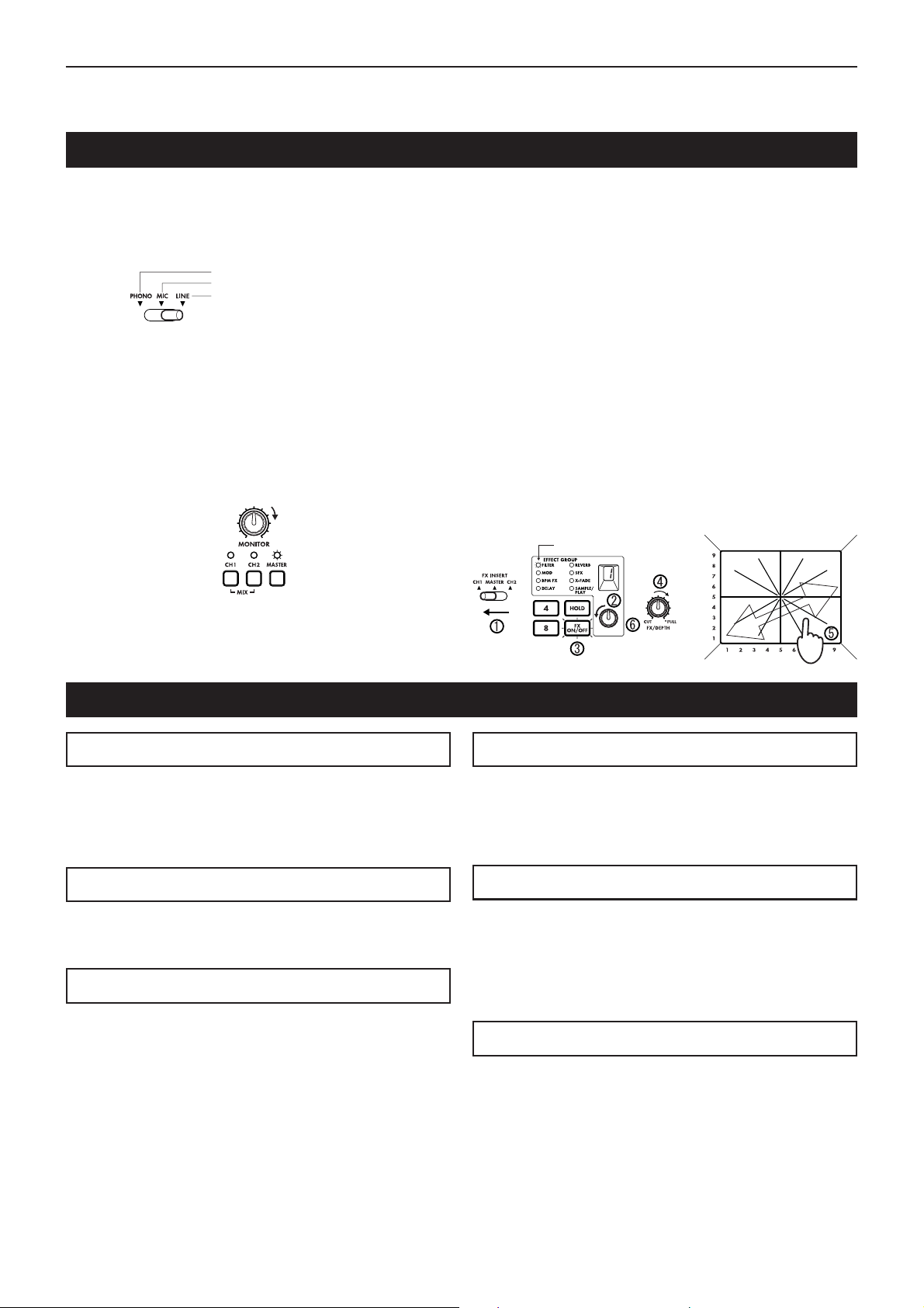
Bedienung
Grundfunktionen
Bedienung
1) Schließen Sie Ihre(n) Plattenspieler oder CD-Player an den
Buchsen CH1 und CH2 an, wie unter "Anschlüsse und
Bedienungselemente des KM-2" (S. 19) beschrieben. Schieben Sie die Eingangswahlschalter (1, 2) für die an den Kanälen 1 und 2 angeschlossenen Geräte auf die jeweils richtige Stellung.
2) Wenn Sie zum Abhören Kopfhörer benutzen, schließen Sie
Ihre Kopfhörer an der Vorderseite an der PHONES-Buchse (F5) an. In dieser Beschreibung gehen wir davon aus,
daß Sie mit Kopfhörern arbeiten.
3) Schalten Sie den POWER-Schalter (R9) ein. Nach maximal 10 Sekunden ist der KM-2 betriebsbereit. Das Hochfahren des Systems ist beendet, sobald die BPM-Anzeige
stehen bleibt.
4) Stellen Sie sicher, daß die Monitor-Wahlschalter (11) auf
"MASTER" gestellt sind, und benutzen Sie den Regler
MONITOR (10) für die Lautstärkeeinstellung der Kopfhörer.
5) Und so hören Sie den Sound von Kanal 1 im Kopfhörer ab:
Stellen Sie den Fader für Kanal 1 (7) auf etwa 50~70% ein.
Wenn die PEAK-LED aufleuchtet, ist das Eingangssignal
zu hoch. Drehen Sie den TRIM-Eingangsregler (3) nach
links, bis die LED nicht mehr aufleuchtet. Bringen Sie den
Bei angeschlossenem Plattenspieler
Bei angeschlossenem Mikrofon
Bei angeschlossenem CD-Spieler usw.
Lautstärke einstellen
Leuchtet
Überblendregler X-FADE (29) auf die Stellung CH1 (ganz
links).
6) Effekte steuern Sie mit dem T ouch Panel (30). Mit der Effektsektion des KM-2 können Sie den Sound steuern, indem
Sie Ihren Finger horizontal (auf der X-Achse) und vertikal
(auf der Y-Achse) auf dem Touch Panel herumfahren. Für
genauere Informationen darüber, welcher Effekt welche
Nummr trägt, und welche Parameter von der X-Achse und
der Y-Achse gesteuert werden, betrachten Sie die "Liste
der Effektprogramme" auf Seite 4.
Hier erfahren Sie, wie Sie einen Effekt auf das Signal von
CH1 legen können.
1 Stellen Sie FX INSERT (12) auf "CH1".
2 Wählen Sie für dieses Beispiel die Programmnummer 1 der
Gruppe "FILTER", indem Sie am Effektprogramm-Regler
(20) drehen.
3 Achten Sie darauf, daß der Schalter FX ON/OFF (25) leuch-
tet.
4 Drehen Sie den Regler FX DEPTH (9) ganz nach rechts.
5 Berühren Sie das Touch Panel (30) - der Effekt ist zu hö-
ren.
6 Drehen Sie am Effektprogramm-Regler (20), um ein ande-
res Effektprogramm aufzurufen.
Leuchtet
Ganz
aufdrehen
Über die BPM-Funktion
Was ist BPM?
BPM steht für "Beats Per Minute" (Schläge pro Minute), und
zeigt so das T empo des Song anhand der Nummer der "Schläge" (Zählzeiten von Viertelnoten) an, die in einer Minute gezählt werden. Bei BPM=120 sind es z. B. 120 Schläge in der
Minute, jeder "Beat" dauert also 0,5 Sekunden. Höhere BPMWerte zeigen schnellere Tempi an.
Erkennung des BPM-Wertes
Es gibt beim KM-2 zwei Arten, den BPM-W ert einzustellen: die
automatische BPM-Erkennung oder die TAP-Eingabe (Mitschlagen des Tempos).
Automatische BPM-Erkennung
1) Wählen Sie mit dem Schalter FX INSERT (12) den Kanal
(CH1 oder CH2), in dem der Titel läuft, dessen BPM Sie
erkennen möchten.
2) Drücken Sie gleichzeitig die ADJUST-Tasten % und fi (18).
Dadurch wird der BPM-Wert automatisch erkannt und in
der BPM-Anzeige (17) angezeigt.
3) Drücken Sie % oder fi, um die Erkennung abzuschließen
und den BPM-Wert zu übernehmen.
✩ Wenn Sie den Schalter FX INSERT (12) betätigen oder er-
neut % und fi gleichzeitig drücken, während die automatische BPM-Erkennung aktiv ist, wird die Erkennung abgebrochen.
✩ Die automatische BPM-Erkennung arbeitet nicht, wenn der
Schalter FX INSERT (12) auf "MASTER" gestellt ist.
✩ Unter Umständen ist es bei komplexen Schlagzeug-Phrasen
nicht möglich, den BPM-Wert zu erkennen. Benutzen Sie in
solchen Fällen die TAP-Taste, um das T empo einzugeben.
✩
Die AUTO BPM-Funktion arbeitet im Bereich von 80–160 bpm.
Verwendung der TAP-Eingabe für die BPM-Einstellung
Drücken Sie die TAP-T aste (19) zwei- oder mehrmals im SongTempo. Das Tempo Ihrer Anschläge wird in der BPM-Anzeige
(17) dargestellt.
✩ Die BPM-Einstellung per T AP-T aste kann auch dann durch-
geführt werden, wenn der Schalter FX INSERT (12) auf
MASTER eingestellt ist.
Feineinstellung des BPM-Wertes
Nachdem der BPM-Wert erkannt oder eingegeben wurde, können Sie mit den ADJUST-Tasten % und fi (18) eine Feineinstellung des BPM-Wertes vornehmen.
✩ Wenn Sie die Einstellung des FX-INSERT-Schalters (12)
ändern, wird der vorher für diesen Kanal erkannte BPMWert angezeigt.
✩ Bei der ersten BPM-Erkennung wird der voreingestellte Wert
BPM=120 angezeigt.
BPM-Effekte
Wenn Sie ein Effektprogramm der BPM FX-Gruppe anwählen,
verhält sich der Effekt stets synchron zum BPM-Wert des jeweils anliegenden Signals.
Wählen Sie also z.B. das BPM FX-1-Programm BPM DELA Y2,
entspricht die durch Berühren des Touch Panels (30) im Bereich 3–5 der horizontalen (X-)Achse eingestellte Delay-Länge genau der Hälfte des jeweiligen BPM-Werts. Für nähere
Informationen zu den anderen BPM-Effekten siehe seite 4,
“Liste der Effektprogramme”.
✩ Wenn Sie die TAP-T aste (19) benutzen, um den BPM-Wert
einzugeben, wird der BPM-Wert sofort auf den Effekt angewendet.
✩ Wenn Sie die automatische BPM-Erkennung benutzen, wird
der BPM-Wert auf den Effekt angewendet, wenn Sie die
ADJUST-Tasten % oder fi (18) drücken.
5
Page 24
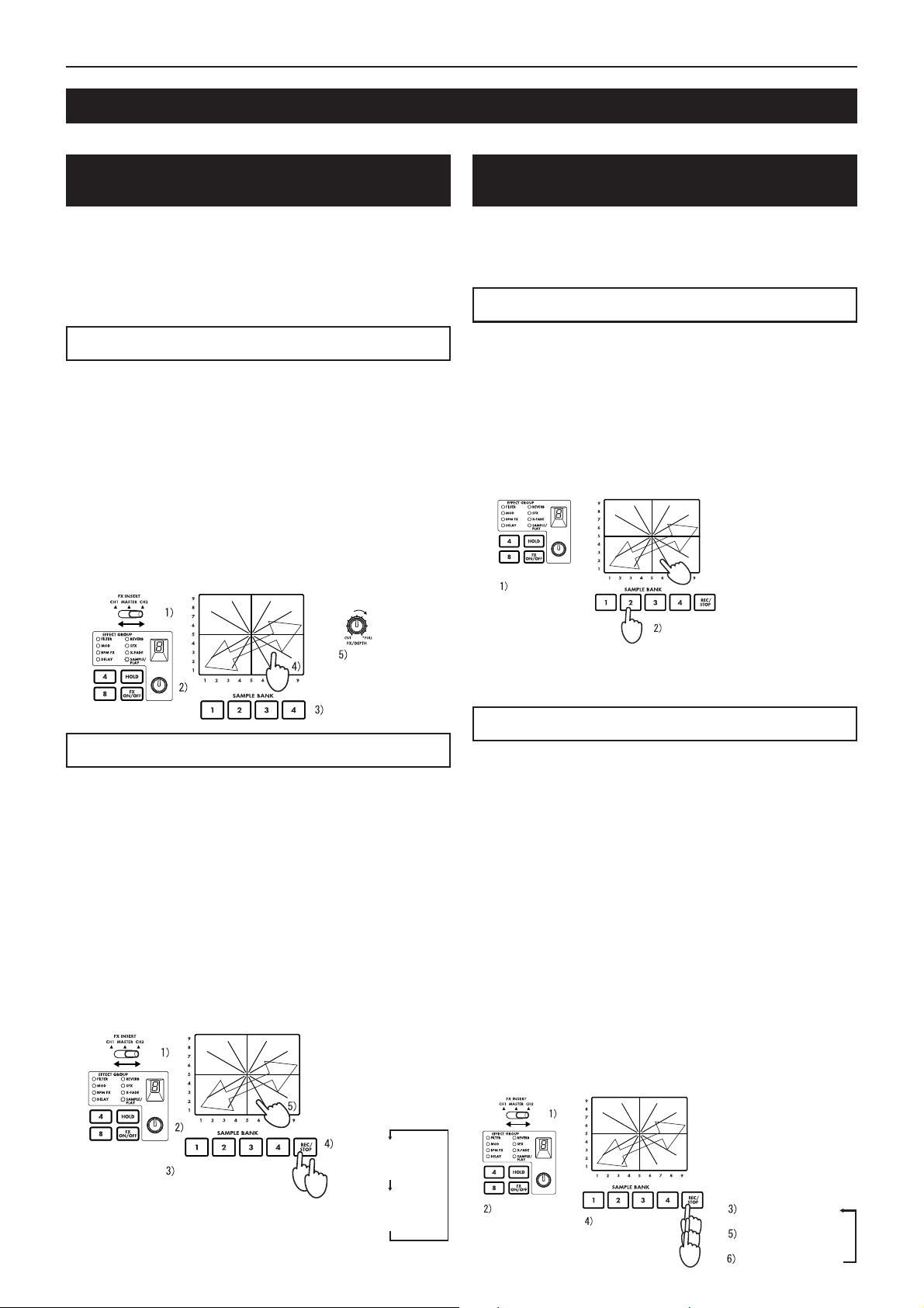
Bedienung
Über die SAMPLE/PLAY-Effekte
Mit der Sampling-Funktion des KM-2 können Sie vier verschiedene, jeweils ca. 6 Sekunden lange Samples aufnehmen.
Aufnahme und Wiedergabe bei ausgewähltem SAMPLE/PLAY-Effektprogramm
Sie können Samples aufnehmen oder wiedergeben, wenn ein
SAMPLE/PLAY-Effektprogramm ausgewählt wurde. Die
Wiedergabegeschwindigkeit, Rückwärtswiedergabe usw. können mit dem Touch Panel gesteuert werden.
✩ Die Wiedergabesteuerung hängt vom gewählten Effekt-
programm ab. Betrachten Sie die "Liste der Effektprogramme" auf Seite 4.
Wiedergabe-Bedierung
1) Wählen Sie mit dem Schalter FX INSERT (12) den Kanal,
in den die Sample-Wiedergabe gemischt werden soll.
2) Wählen Sie ein Programm der Gruppe SAMPLE/PLAY.
3) Wählen Sie mit den SAMPLE-BANK-Tasten 1–4 (26) den
Sample, den Sie abspielen möchten. (Der Sample erklingt
jetzt noch nicht.)
4) Wenn Sie das Touch Panel (30) berühren, erfolgt die Wiedergabe je nachdem, wo Sie das Panel berührt haben.
5) Mit dem Regler FX DEPTH (9) können Sie die Wiedergabelautstärke einstellen. Wenn der Regler sich in der mittleren
Position befindet, wird die Sample-Wiedergabe im Verhältnis 1:1 mit dem Signal des Kanals gemischt. In der maximalen Position ist bei der Wiedergabe nur der Sample zu
hören; das Eingangssignal des Kanals ist unhörbar.
Wiedergabe über das
Touch Panel
Wiedergabelautstärke
(auswählen)
Aufnahme und Wiedergabe, wenn kein SAMPLE/
PLAY-Effektprogramm ausgewählt ist
Sie können auch dann Phrasen aufnehmen und abspielen (einfache Wiedergabe), wenn kein SAMPLE/PLA Y -Effektprogramm
ausgewählt wurde.
Wiedergabe und Aufnahme sind nicht möglich, wenn FX ausgeschaltet ist.
Wiedergabe - Bedienung
1)
Wählen Sie mit dem Effektprogramm-Regler (20) ein Programm,
das sich nicht in der Gruppe SAMPLE/PLAY befindet.
2) Wenn Sie eine der SAMPLE-BANK-Tasten 1–4 (26) drükken, wird der entsprechende Sample abgespielt, so lange
Sie die Taste gedrückt halten. Der Sample läuft jedoch nur
in normaler Geschwindigkeit, und wird mit der Lautstärke, in
der er aufgenommen wurde, fortlaufend wiederholt ("Loop").
✩ Wenn Sie während der Sample-Wiedergabe das Touch
Panel (30) bedienen, können Sie einen Effekt auf den
Sample legen.
✩ Der Sample wird in den Kanal gemischt, der mit dem Schal-
ter FX INSERT (12) eingestellt wurde.
Sie können einen
Effekt auf den wiedergegebenen Sound
legen
Anderen Effekt
als SAMPLE/
PLAY wählen
Läuft nur, wenn gedrückt
✩ Drücken Sie bei laufender Wiedergabe den HOLD-Schal-
ter (24), wird die Wiedergabe angehalten.
Drücken Sie anschließend eine der SAMPLE BANK-T asten
1–4 (26), setzt dies die HOLD-Funktion wieder außer Kraft.
Aufnahme - Bedienung
Aufnahme - Bedienung
1) Wählen Sie mit dem Schalter FX INSERT (12), ob Sie das
Signal von CH1 (Kanal 1), CH2 (Kanal 2) oder des MASTER aufnehmen möchten.
2) Wählen Sie mit dem Effektprogramm-Regler (20) ein Programm der Gruppe SAMPLE/PLAY. Für dieses Beispiel
wählen Sie bitte SAMPLE/PLAY-1.
3) Wählen Sie mit den SAMPLE-BANK-Tasten 1–4 (26) eine
der Sample-Bänke 1–4, in denen Sie aufnehmen möchten.
4) Starten Sie die Aufnahme mit der REC/STOP-Taste (27). Die
Aufnahme stoppt, wenn Sie die REC/STOP-Taste nochmals
drücken (oder wenn die maximale Aufnahmezeit erreicht ist).
✩
Während der Aufnahme leuchtet die LED der REC/ST OP-T aste (27).
5) Berühren Sie das Touch Panel (30), und die aufgenommene
Phrase wird abgespielt. Die Art und W eise, auf die die Phrases
gespielt werden, hängt vom gewählten Programm ab. Beachten Sie dazu die "Liste der Effektprogramme" auf Seite 4.
Wiedergabe über das
Touch Panel
1. Mal:
BANK für die
Aufnahme
auswählen
6
Aufnahme starten
(LED leuchtet)
2. Mal: Aufnahme
stoppen
(LED erlischt)
1) Wählen Sie mit dem Schalter FX INSERT (12), ob Sie das
Signal von CH1 (Kanal 1), CH2 (Kanal 2) oder des MASTER aufnehmen möchten.
2)
Wählen Sie mit dem Effektprogramm-Regler (20) ein Programm, das sich nicht in der Gruppe SAMPLE/PLA Y befindet.
3) Schalten Sie mit der REC/STOP-Taste (27) in Aufnahmebereitschaft. (Diesen Status können Sie mit der Taste FX
ON/OFF (25) wieder deaktivieren.)
✩ Die LED der REC/STOP-Taste (27) blinkt, um die Aufnah-
mebereitschaft anzuzeigen.
4) Wählen Sie mit den SAMPLE-BANK Tasten 1–4 (26) eine
der Sample-Bänke 1–4, in denen Sie aufnehmen möchten.
(Der Sample ist jetzt noch nicht zu hören.)
5) Starten Sie die Aufnahme durch nochmaliges Drücken der
REC/STOP-Taste (27).
6)
Die Aufnahme stoppt, wenn Sie die REC/STOP-Taste nochmals
drücken (oder wenn die maximale Aufnahmezeit erreicht ist).
✩ Während der Aufnahme leuchtet die LED der REC/STOP-
Taste (27).
✩ Wenn Sie erneut aufnehmen möchten, wiederholen Sie den
Vorgang ab Schritt 3.
✩ Wenn Sie aufnehmen, während ein Effektprogramm aus
einer anderen Gruppe als SAMPLE/PLAY gewählt ist, wird
der Klang des Effekts, der vom Touch Panel gesteuert wird,
ebenfalls aufgenommen.
Anderen Effekt
als SAMPLE/
PLAY wählen
BANK für die
Aufnahme
auswählen
Aufnahmebereit
(LED blinkt)
Aufnahme starten
(LED leuchtet)
Aufnahme stoppen
(LED erlischt)
Page 25

Bedienung / Kalibrierung des Crossfaders
Sample speichern - "WRITE"
Phrasen, die Sie mit der Taste REC/STOP aufgenommen haben, befinden sich nur im temporären Arbeitsspeicher des KM2 und gehen beim Ausschalten verloren. Wenn Sie die Samples
behalten möchten, müssen Sie sie mit der WRITE-Funktion
speichern. Andererseits werden Phrasen, die Sie bereits mit
WRITE gespeichert haben, durch neue Aufnahmen nicht gelöscht, solange Sie nicht erneut die WRITE-Funktion durchführen.
1) Drücken und halten Sie zwei Sekunden lang die WRITETaste (28). Die WRITE-LED beginnt zu blinken, und der
KM-2 ist "in Speicherbereitschaft".
2) Drücken Sie die SAMPLE-BANK-Taste(n) 1–4 (26), die Sie
speichern möchten. (Die ausgewählte SAMPLE-BANK-LED
blinkt.) Sie können auch zwei oder mehr Sample-Bänke
zum Speichern auswählen.
✩ Wenn Sie zu diesem Zeitpunkt die TAP-T aste (19) oder den
Schalter FX ON/OFF (25) drücken, wird der WRITE-Vor-
gang abgebrochen.
3) Drücken Sie die WRITE-Taste (28) erneut, beginnt der
Speichervorgang.
Je Speicher-Bank dauert der Write-Vorgang maximal 20
Sekunden.
Der Fortschritt des Speichervorgangs lässt sich während
des Speicherns an der Pegelanzeige ablesen. Nach
Abschluss des Speichervorgangs erlischt die WRITE-LED.
✩ Unterbrechen Sie den Speichervorgang niemals durch Aus-
schalten des Geräts, da dies unweigerlich zum Verlust der
Daten führt.
Über die Programmzuweisungstasten (MAP)
Ihre meistverwendeten Effektprogramme können für schnellstmöglichen Abruf den programmierbaren MAP-Tasten 1–8 zugewiesen werden. Diese Programmzuweisungstasten speichern nicht nur die Effektprogrammnummer , sondern auch den Zustand
der HOLD-Taste, die HOLD-Position, und andere Daten (siehe unten).
Auf einer MAP-Taste gespeicherte Daten
• Nummer der Effektprogramm-Gruppe
• Status der HOLD-Taste (Ein/Aus) und HOLD-Position (Koordinaten)
• Bei der Gruppe BPM FX der BPM-Wert, der beim Speichern der MAP angezeigt war
• Bei der Gruppe SAMPLE/PLAY die Nummer der verwendeten SAMPLE BANK (diejenige der Sample-Bänke 1–4,
die beim Speichern der MAP-Taste ausgewählt war)
1) Drücken Sie diejenige der MAP-Tasten 1–8 (23), unter der
Sie speichern möchten.
2) Wählen Sie mit dem Effektprogramm-Regler (20) das Effektprogramm, das Sie speichern möchten. Wenn Sie mit HOLD
"ON" (eingeschaltet) speichern möchten, schalten Sie die
HOLD-T aste ein (LED leuchtet), und berühren Sie das Touch
Panel (30) an den gewünschten Koordinaten.
3) Drücken und halten Sie die vorher gewählte (leuchtende)
MAP-Taste (23) zwei Sekunden lang. Wenn die MAP-LED
dreimal aufgeblinkt hat, wurden die Daten gespeichert.
• Die Zahl in der Anzeige der Effektnummer blinkt ebenfalls.
MAP-Taste speichern
Kalibrierung des Crossfaders
Der KM-2 bietet die Möglichkeit, den Einsatzpunkt des Crossfaders (Überblendreglers) beim Überblenden zwischen CH 1 und
CH 2 individuell einzustellen. (Ab Werk ist der Crossfader so eingestellt, daß der Überblendvorgang bereits bei der geringsten
Fader-Bewegung einsetzt.)
1) Schalten Sie das Gerät aus.
2) Schalten Sie das Gerät bei gedrückter WRITE-Taste (28) und gleichzeitig gedrückter REC/STOP-Taste (27) wieder ein.
Anschließend sehen Sie im BPM-Display die Anzeige “CAL”; Sie befinden sich im Kalibrierungs-Modus.
3) Betätigen Sie nun den Crossfader (29), leuchten die LEDs der SAMPLE BANK-Tasten 1–4 (26) entsprechend ihrer Handbe-
wegung auf.
Der Punkt, an dem das Licht von LED 1 nach LED 2 wechselt, zeigt den Einsatzpunkt des Crossfaders beim Überblenden
von CH 1 nach CH 2 an.
Der Punkt, an dem das Licht von LED 4 nach LED 3 wechselt, zeigt den Einsatzpunkt des Crossfaders beim Überblenden
von CH 2 nach CH 1 an.
4) Bewegen Sie den Crossfader nun an den Punkt, an dem das Überblenden von CH 1 nach CH 2 beginnen soll.
5) Speichern Sie den Crossfader-Einsatzpunkt durch Drücken der REC/STOP-Taste (27).
6) Zur Einstellung des Crossfader-Einsatzpunktes von CH 2 nach CH 1 wiederholen Sie die Schritte 4 und 5 entsprechend.
7) Drücken Sie nun die WRITE-Taste (28), werden die zuvor eingestellten Crossfader-Daten im internen Speicher des KM-2
gespeichert. Anschließend ist das Gerät wieder betriebsbereit.
✩ Es ist nicht möglich, den Crossfader-Einsatzpunkt so einzustellen, daß BANK LED 2 und 3 gleichzeitig leuchten.
✩ Der Überblendvorgang setzt frühestens nach 3,0 mm des Crossfader-Regelwegs (links bzw. rechts) ein. Es ist nicht möglich,
mit dem Überblenden weiter links oder rechts zu beginnen.
(Stellen Sie den Crossfader entsprechend Schritt 5 so ein, daß sich dieser in Links- bzw. Rechtsanschlagposition befindet,
wird der Einsatzpunkt automatisch auf den Mindestwert gesetzt.)
✩ Die Kalibrierungsdaten bleiben auch bei ausgeschaltetem Gerät erhalten.
7
Page 26

Technische Daten
Technische Daten
Eingangs-Sektion
BPM : 40~999 (TAP)
80~160 (AUTO)
PHONE INPUT : Eingangsimpedanz 40 kOhm, Bezugs-
pegel -40 dBu
LINE INPUT : Eingangsimpedanz 10 kOhm, Bezugs-
pegel -10 dBu
MIC INPUT : Eingangsimpedanz 9 kOhm, Bezugs-
pegel -40 dBu
MASTER OUTPUT : Ausgangsimpedanz 600 Ohm, Bezugs-
pegel 0 dBu
MONITOR OUTPUT : Ausgangsimpedanz 33 Ohm
Effekt-Sektion
Sampling-Frequenz : 44,1 kHz
AD/DA : 20 Bit
Maximale Aufnahmedauer
Effektprogramme : 80
Programmzuordnungen : 8
Leistungsaufnahme : 12,3 W (typ.)
Abmessungen : B ✕ H ✕ T = 218 mm ✕90 mm ✕ 206
Gewicht : 1,8 kg
Mitgeliefertes Zubehör : Netzadapter
Optionen : Crossfader-Einheit
: 23,7 Sekunden
mm (einschließlich Vorsprüngen)
:
Schutzabdeckung für das Touch Panel
8
Page 27

目次/安全上の注意
目次
安全上のご注意........................................................................................................................1
接続および各部の名称、機能 .................................................................................................. 2
エフェクト・プログラム・リスト ........................................................................................... 4
操作方法 .................................................................................................................................. 5
クロスフェーダの調整について .............................................................................................. 7
仕様/保証規定........................................................................................................................8
安全上のご注意
火災・感電・人身傷害の危険を防止するには以下の指示を守ってください
警告
● 本製品を使用する前に、以下の指示をよく読んでください。
● 付属のACアダプターは、必ずAC100Vの電源コンセントにACアダプターを差し込んでください。
● 次のような場合には直ちに電源を切り、ACアダプター使用時はコンセントから抜きます。そして、コルグ営業所ま
たはお買い上げになった販売店に修理を依頼してください。
○ ACアダプターの電源コードやプラグが破損したとき
○ 異物が内部に入ったり、液体がこぼれたとき
○ 製品が(雨などで)濡れたとき
○ 製品に異常や故障が生じたとき
● 次のような場所での使用や保存はしないでください。
○ 温度が極端に高い場所(直射日光のあたる場所、暖房機器の近く、発熱する機器の上など)
○ 水気の近く(風呂場、洗面台、濡れた床など)や湿度の高い場所
○ ホコリの多い場所
● 修理/部品の交換などで、取扱説明書に書かれている以外のことは、絶対にしないでください。必ず最寄りのコル
グ営業所またはコルグ営業技術課に相談してください。
● ACアダプターのコードを無理に曲げたり、上に重いものを乗せたりしないでください。コードに傷がつき危険です。
● 本製品をヘッドフォン、アンプ、スピーカーと組み合わせて使用した場合、設定によっては永久的な難聴になる程
度の音量になります。大音量や不快な程度の音量で長時間使用しないでください。万一、聴力低下や耳鳴りを感じ
たら、専門の医師に相談してください。
● 本製品に、異物(燃えやすいもの、硬貨、針金など)や液体(水やジュースなど)を絶対にいれないでください。
● 本製品およびACアダプターを分解したり、改造したりしないでください。
注意
● 本製品は正常な通気が妨げられることのない所に設置して、使用してください。
● 本製品はマイクロコンピュータを使用した機器です。このため他の電気機器を接近して同時にご使用になります
と、それらに雑音が入ることがあります。逆に他の電気機器から本製品が雑音を受けて誤動作する場合があります。
● ACアダプターをご使用になる場合は、必ず指定のものをご使用ください。他のアダプターをご使用になりますと故
障の原因となります。また、使用後はACアダプターをコンセントから抜いてください。
● スイッチやつまみに必要以上の力を加えますと故障の原因となりますので注意してください。
● 外装のお手入れは、必ず乾いた柔らかい布で軽く拭いてください。ベンジンやシンナー系の液体は絶対にご使用に
ならないでください。(コンパウンド質、強燃性のポリッシャーも不可)。
● ACアダプターをコンセントから抜くときは、絶対にコードを引っぱらないでください。故障の原因となります。
1
Page 28

接続および各部の名称、機能
接続および各部の名称、機能
上 面
1. チャンネル1 ・インプット・セレクト・
スイッチ
チャンネル1の入力ソースを選択します。
注意: 入力ソースにマイクを選択する場
合は、前面のTALK OVER ON/OFFス
イッチ(F1)をOFFにしてください。
LINE:CDプレーヤーなどMIC:マイク
PHONE:ターンテーブル、
TALK OVER
2. チャンネル2 ・インプット・セレクトス
イッチ
チャンネル2の入力ソースを選択します。
3. PEAK(ピーク・インジケーター)、TRIM
(トリムつまみ)
最大音量が入力されてもピーク・インジ
ケーターが点灯しないようにトリムつま
みを調整します。
4. HIGH EQ(ハイ・イコライザー)
高域イコライザーのブースト/ カットを設
定します。
5. MID EQ(ミドル・イコライザー)
中域イコライザーのブースト/ カットを設
定します。
6. LOW EQ(ロー・イコライザー)
低域イコライザーのブースト/ カットを設
定します。
7. チャンネル1・フェーダー
チャンネル1の音量を調整します。
8. チャンネル2・フェーダー
チャンネル2の音量を調整します。
9. FX DEPTH(エフェクト・デプスつまみ)
CUTの位置でまったくエフェクトのかか
らない音になり、FULLでもっともエフェ
クトがかかった音になります。通常は
FULLの位置で使用してください。
:ON :OFF
前 面
F1. TALK OVER ON/OFF(トーク・オーバー・スイッチ)
このスイッチをO N (スイッチが押し込まれた状態)にすると、
マイク入力の音声がマスター・アウトプットにミックスされま
す。
✩ マイクをチャンネル1 の入力として使用する場合は、トーク・
オーバー・スイッチはOFFにしてください。
F2. MIC LEVEL(マイク・レベルつまみ)
マイクの音量を設定します。
F3.MIC(マイク入力端子)
マイクを接続します。
注:マイク入力は、アンバランス入力です。
F4. X-FADE(クロス・フェーダー・カーブ・スイッチ)
クロス・フェーダーのカーブを選択します。
F5. PHONES(ヘッドフォン端子)
ヘッドフォンを接続します。
2
Page 29

接続および各部の名称、機能
10. MONITOR(モニターつまみ)
前面のPHONES端子(F5)の出力レベル
を設定します。
11. モニター・セレクト・スイッチ
CH1: チャンネル1 のサウンドをモニター
できます。
CH2: チャンネル2 のサウンドをモニター
できます。
MASTER:マスター出力に出ているサウン
ドをモニターできます。
MIX(CH1とCH2を同時に押す):ヘッド
フォンのLch でチャンネル1 のサウンド、
Rchでチャンネル2のサウンドをモニター
できます。
12. FX INSERT(エフェクト・インサート・
スイッチ)
CH1:チャンネル1 のプリ・フェーダーの
位置にエフェクトを挿入します。
CH2:チャンネル2 のプリ・フェーダーの
位置にエフェクトを挿入します。
MASTER:マスター(クロス・フェーダー
の後ろ)にエフェクトを挿入します。
☆ 一部の特殊なエフェクト・プログラム
では、エフェクトが挿入される位置が
異なります。(P . 4 「エフェクト・プ
ログラム・リスト」参照)。
13. レベル・メーター・モード・スイッチ
レベル・メーター表示のモードを選択し
ます。このスイッチを押すたびに、下記
の2種の表示モードが切り替わります。
CH1/CH2:チャンネル1 、2 (プリ・フェー
ダー)の入力レベルをそれぞれ表示します。
L/R:マスター出力のLch、Rchのレベルを
それぞれ表示します。
CH1/CH2は最大で0dB〜1dBで使用して
下さい。
14. ULTRA BOOST(ウルトラ・ブーストつ
まみ)
新開発ウルトラ・ブースト効果の強さを
設定します。このつまみを右にまわすほ
ど、低音をブーストすると同時に、バ
ス・ドラムやベース音のエッジを強調し
ます。
15. MASTER(マスター・ボリューム)
MASTER OUTPUT端子(R6)から出力
される音の音量を設定します。
16. BOOTH(ブース・ボリューム)
BOOTH OUTPUT端子(R7)から出力さ
れる音の音量を設定します。
17. BPM(BPM表示機)
曲のテンポの速さ、いわゆるB P M を表示
します。
18. ADJUST(BPMアジャスト・キー)
TAPキー(19)または、オートBPM 検出に
よって設定されたBPMを細かく調整します。
△ でB PMの数字が増えます(テンポが早
くなる)。
▽ でB PMの数字が減ります(テンポが遅
くなる)。
19. TA P(タップ・キー)
曲のビートに合わせてこのキーを2回以上
押すと、そのビートを検出してBPM表示
機(17)にテンポが表示されます。
☆ 検出可能なBPMは、40〜999です。
☆ BPM機能については、P.5「BPM機能
について」を参照ください。
20. エフェクト・プログラムつまみ
このつまみを回してエフェクトのプログ
ラムを選択します。エフェクト・プログ
ラムは、FILTER(フィルター)、MOD
(モジュレーション)など8種のグループ
に分かれており、各グループにそれぞれ
10個、合計80個のプログラムがプリセッ
トされています。
21. エフェクト・グループ・ディスプレイ
現在選択されているエフェクト・プログ
ラムのグループ名を表示します。
22. エフェクト・ナンバー・ディスプレイ
現在選択されているエフェクト・プログ
ラム・ナンバーを表示します。
☆ 各プログラムにどんなエフェクトが設
定されているかは、P. 4「エフェクト・
プログラム・リスト」を参照くださ
い。
23. プログラム・マップ・キー1–8
8 0 個のエフェクト・プログラムのうち、自
分のお気に入りのプログラムを8 個までプ
ログラム・マップ・キーにアサイン(割り
当て)することができ、スピーディーな
プログラムの切り替えが可能です。
24. HOLD(ホールド・スイッチ)
このスイッチが点灯しているときは、
タッチ・パネル(3 0 )がホールド状態に
なります。タッチ・パネルから指を離し
ても、最後に触っていた位置でのエフェ
クトが保持されます。
25. FX ON/OFF(エフェクトON/OFFスイッチ)
このスイッチを押すごとに、点灯(エ
フェクトON)、消灯(エフェクトOFF)
を繰り返します。
26. SAMPLE BANK(サンプル・バンク・
キー1–4)
サンプリングされたフレーズがそれぞれ
にメモリされています。SAMPLE/PLAY
のエフェクト・プログラム以外では、1 – 4
のキーを押すと、押している間だけ、フ
レーズが再生されます。
☆ 再生音は、FX INSERTスイッチ(12)
で選択しているチャンネル側に出てき
ます。
☆ 再生音にさらにエフェクトをタッチ・
パネルで付加することもできます。
27. REC/STOP(レコード・キー)
SAMPLE/PLAYのエフェクト・プログラ
ムを選択しているときに、このキーを押
すと、録音が開始され、再度押すと録音
が終了します。
詳しくは、P.6「SAMPLE/PLAYエフェク
トについて」を参照ください。
28. WRITE(ライト・キー)
新たにサンプリングしたフレーズは、電
源を切ると消えてしまいます。フレーズ
を保存するときは書き込みの作業が必要
です。ライトの操作については、P . 7 「サ
ンプルの保存について」を参照ください。
29. X-FADE(クロス・フェーダー)
チャンネル1 、チャンネル2 のミックス比
を設定します。
30. タッチ・パネル
エフェクトの音色を変化させます。
背 面
R1. CH1 PHONO(チャンネル1・フォノ入力端子)
R2. CH2 PHONO(チャンネル2・フォノ入力端子)
ターン・テーブルを接続します。
R3. CH1 LINE IN(チャンネル1・ライン入力端子)
R4. CH2 LINE IN(チャンネル2・ライン入力端子)
CDなどを接続します。
R5. GND(グランド端子)
ターン・テーブルのGND(グランド)線を接続します。
R6. MASTER OUTPUT(マスター・アウトプット端子)
MASTERボリューム(15)で設定した音量で出力されます。
R7. BOOTH OUTPUT(ブース・アウトプット端子)
BOOTHボリューム(16)で設定した音量で出力されます。
R8. ~AC9V(電源端子)
付属の電源アダプターを接続します。
R9. POWER(電源スイッチ)
☆ 電源を入れてから、KM-2のシステムが起動して使用可能にな
るまでには最長10秒かかります。
3
Page 30

エフェクト・プログラム・リスト
エフェクト・プログラム・リスト
KM-2 EFFECT PROGRAM LIST
EFFECT GROUP PROG TITLE X Y BPM
FILTER 0 RESONANCE FILTER FREQUENCY RESONANCE
MODULATION 0 VIBRATE SPEED DEPTH
BPM FX 0 BPM DELAY1 X1-3 X3-5 X5-7 X7-9 FEEDBACK
DELEY 0 TAPE ECHO DELAY TIME FX LEVEL,FEEDBACK
REVERB 0 HALL REVERB TONE REVERB LEVEL
SFX 0 STEP MODULATION MOD DEPTH FX LEVEL
X-FADE 0 REVERB X-FADE1★ CH1 CH2 CH1 CH2 REV LEVEL
SAMPLE/PLAY 0 LOOP1(AUTO REC START) LOOP END TIME CONTROL PLAYBACK LEVEL
★のプログラムについて
FXINSERTの位置に拘らずサンプル録音の取り口はMASTERとなり、CH1、CH2及びCH1&2をPHONES端子よりモニター時はディレイリバーブが掛からない状態でモニターされます
AUTORECSTARTについて
SAMPLE/PLAY0番選択時の録音はAUTORECSTARTとなります。RECキ−を押した後、信号が入力されると録音が自動的に開始されます
X-FADEエフェクトグループおよびDELAY-3では、FXINSERTスイッチがMASTER時には、サンプル再生音にエフェクトはかかりません。
タッチパネルを左端の中央から右端中央にむかって山なりになぞってクロスフェ−ドします
タッチパネルを右端の中央から左端中央にむかって山なりになぞってクロスフェ−ドします
4
タッチパネルを右端の中央から左端中央にむかってU字になぞってクロスフェ−ドします
1 ISOLATOR LPF/HPF TYPE HI CUT <-> LOW CUT NO ASSIGN
2 WAH FILTER SPEED DEPTH
3 DIST+VOICE FILTER TALKING DISTORTION
4 DIST+FILTER FREQUENCY DISTORTION
5 MANUAL PHASER FREQUENCY RESONANCE
6 PAN BY HPF X-FADE PAN FREQUENCY
7 DIST+ISOLATOR LOW-MID-HI DISTORTION
8 MID FREQ ISOLATOR MID BOOST<->CUT NO ASSIGN
9 3BAND ISOLATOR HI CUT <-> LOW CUT MID LEVEL
1 PHASER SPEED FREQUENCY
2 AUTO PAN LFO SPEED DEPTH
3 FLANGER+FILTER FLANGER SPEED FILTER FREQ
4 DIST+PHASER FREQUENCY FX LEVEL
5 MANUAL FLANGER1 DELAY TIME RESONANCE
6 MANUAL FLANGER2 DELAY TIME RESONANCE
7 PITCH SHIFT Lch PITCH Rch Pitch
8 TREMOLO SPEED DUTY
9 STEP PHASER MOD STEP RESONANCE
1 BPM DELAY2(TAPE ECHO TYPE ) X1-3 X3-5 X5-7 X7-9 FEEDBACK
2 BPM MULTI TAP DELAY1 NO ASSIGN LEVEL DELAY TIME
3 BPM MULTI TAP DELAY2 NO ASSIGN LEVEL DELAY TIME
4 BPM MULTI TAP DELAY3 NO ASSIGN FEEDBACK DELAY TIME
5 BPM PHASER X1-3 X3-5 X5-7 X7-9 RESONANCE
6 BPM FLANGER X1-3 X3-5 X5-7 X7-9 RESONANCE
7 BPM TREMOLO X1-3 X3-5 X5-7 X7-9 DEPTH
8 BPM STEP PHASER FREQUENCY(MANUAL) RESONANCE SPEED
9 BPM STEP FLANGER STEP SPEED RESONANCE SPEED
1 DELAY DELAY TIME FX LEVEL,FEEDBACK
2 DELAY DELAY TIME FX LEVEL,FEEDBACK
3 DELAY (POST FADER TYPE) ★ DELAY TIME DELAY LEV
4 MULTI TAP DELAY TONE FEEDBACK
5 LONG DELAY FEEDBACK FX LEVEL DELAY TIME
6 PING PONG DELAY DELAY TIME FEEDBACK
7 TALK MOD+DELAY TALKING DELAY LEVEL
8 FILTER +DELAY FILTER FREQ RESONANCE
9 DUB+DELAY DELAY TIME TONE
1 GATE REVERB1 TONE REVERB LEVEL
2 PLATE REVERB REV TIME REVERB LEVEL
3 GATE REVERB2 FREQUENCY REVERB LEVEL
4 REVERB+DELAY DELAY FEEDBACK REVERB LEVEL
5 REVERB+DELAY DELAY TIME REVERB LEVEL
6 TALK MOD+REVERB TALKING RESONANCE
7 FILTER+REVERB FILTER FREQ REVERB LEVEL
8 3D PAN L<->R PAN REVERB LEVEL
9 ROOM REVERB TONE REVERB LEVEL
1 RING MOD+FILTER RING FREQ FILTER FREQ
2 SIN WAVEFORM OSCLATOR PITCH OSC LEVEL
3 BPM DELAY + ISOLATOR ISOLATOR LOW-MID-HI DRY/WET BALANCE DELAY TIME
4 RING +DELAY TIME RING+DELAY BALANCE
5 TREMOLO+DELAY TIME + LFO SPEED DLY TREM X-FADE
6 SPECIAL ECHO TIME FX LEVEL
7 VOICE OSCLATOR PITCH CHARACTER
8 SQUARE WAVEFORM OSCLATOR PITCH OSC LEVEL
9 AQUA SPEED FX LEVEL
1 REVERB X-FADE2★ CH1 CH2 CH1 CH2 Y:5-9 CH1 REV LEVEL
2 ISOLATOR X-FADE★ CH1 CH2 CH1 CH2 Y:5-9 HI CUT (CH1), LOWCUT(CH2)
3 FILTER X-FADE2★ CH1 CH2 CH1 CH2 FILTER FREQ
4 RESONANCE FILTER X-FADE★ CH1 CH2 CH1 CH2 Y:5-9 LPF FREQ (CH1), LOWCUT(CH2)
5 BPM DELAY X-FADE★ CH1 CH2 CH1 CH2 Y:5-9 CH1 DLY LEVEL
6 PHASER X-FADE★ CH1 CH2 CH1 CH2 PHASING LEVEL
7 TAPE ECHO X-FADE★ CH1 CH2 CH1 CH2 DRY/WET BALANCE
8 FLANGER+REV X-FADE★ CH1 CH2 CH1 CH2 FLANGER+REV LEVEL
9 STEP MOD X-FADE★ CH1 CH2 CH1 CH2 STEP MOD LEVEL
1 FORWARD & REVERSE FORWARD & REVERSE PLAYBACK LEVEL
2 FORWARD & REVERSE(Hi SPEED) FORWARD & REVERSE PLAYBACK LEVEL
3 SCRATCHING SCRATCH Y:5-9:GATE ON
4 SCRATCHING WITH FILTER SCRATCH FILTER FREQ
5 TIME STRETCH SLOW <-> FAST TEMPO PLAYBACK LEVEL
6 SCRATCHING WITH BPM DELAY ★ SCRATCH DELAY LEVEL DELAY TIME
7 LOOP2 LOOP START TIME CONTROL PLAYBACK LEVEL
8 FORWARD & REVERSE with DELAY FORWARD & REVERSE DELAY LEVEL
9 FORWARD&REVERSE with SFX FORWARD & REVERSE SFX CONTROL
1/4BEAT 1/2 BEAT 1/3 BEAT 3/4 BEAT
1/4BEAT 1/2 BEAT 1/3 BEAT 3/4 BEAT
x2BEAT x1 BEAT 1/2 BEAT 1/4 BEAT
x2BEAT x1 BEAT 1/2 BEAT 1/4 BEAT
x1BEAT 1/2 BEAT 1/4 BEAT 1/8 BEAT
Y:1-5 CH2 REV LEVEL
Y:1-5 LOW CUT (CH1), HI CUT(CH2)
Y:1-5 LOW CUT (CH1), LPF FREQ(CH2)
Y:1-5 CH2 DLY LEVEL
Y1-5:GATE OFF
DELAY TIME
DELAY TIME
SPEED
SPEED
SPEED
DELAY TIME
Page 31

操作方法
基本的な使いかた
操作方法
1)P.2「接続および各部の名称」を参照してCH1、CH2にター
ンテ−ブルやCDを接続します。また、接続した機器に合
せチャンネル1 、2 のインプット・セレクトスイッチ(1 、
2)を切り替えてください。
2)再生機器としてヘッドフォンを使用する場合は、前面の
PHONES端子(F5)にヘッドフォンを接続します。
ここではヘッドフォンでモニターしてみましょう。
3)POWERスイッチ(R9)をいれます。KM-2のシステム起動
は、最長10秒かかります。B PM表示機の回転表示が終わ
るとシステム起動を完了します。
4)モニター・セレクト・スイッチ(11)がMASTERになって
ることを確認し、MONITORつまみ(10)でヘッドフォンの
音量を設定してください。
5)CH1の音をヘッドフォンでモニターしてみます。
CH1フェーダー(7)を50〜70%に設定します。PEAKのLED
が点灯する場合は、入力が大きすぎます。LEDが点灯しな
くなるようにTRIMつまみ(3)を左に回します。このとき、
X-FADE(29)はCH1側(左側)に設定してください。
6)エフェクトをタッチ・パネル(30)で操作します。
KM-2のエフェクト部は、タッチ・パネルのX軸(横位置)と
Y軸(縦位置)で音色を変化させることができます。どんな
エフェクトが何番にあり、XとY軸でどんなパラメータが可
変できるかは、P.4「エフェクト・プログラム・リスト」を参
照してください。
ここでは、CH1の信号にエフェクトをかけてみましょう。
1 FX INSERT(12)をCH1に設定します。
2 ここでは、エフェクト・プログラムつまみ(2 0)を回して、
FILTERグループの1番を呼び出してみましょう。
3 FX ON/OFFスイッチ(25)が点灯してることを確認します。
4 FX DEPTHつまみ(9)を右に回しきりにします。
5 タッチ・パネル(30)を触るとエフェクトがかかります。
6 エフェクト・プログラムつまみ(20)を回すとプログラムが
切り替わります。
BPM機能について
BPMとは?
BPMはBEATSPERMINUTEの略で曲のテンポの速さを1分間
の拍数(4分音符何個分か)で表したものです。
BPM=120の場合、1分間に120拍(ビート)
したがって、1 拍(ビ−ト)が0 .5 秒の曲のテンポのことです。
BPMの数字が大きいほど早いテンポの曲ということになります。
BPMの検出の仕方
BPMの設定にはオ−トBPM検出とTAPによるBPM入力の2つ
の方法があります。
オ−トBPM
1)B P M 測定をおこないたい曲が入力されているチャンネル
(CH1またはCH2)をFX INSERTスイッチ(12)で選びます。
2)ADJUSTキー(18)の△▽を同時に押します。すると、BPM
が自動的に検出され、BPM表示機(17)に表示されます。
3)△または▽を押すと検出を終了し、BPMを決定します。
☆ オートBPM検出中に、FX INSERTスイッチ(12)を切換え
たり、△ ▽を同時に押すと、オートBPM検出がキャンセ
ルされます。
☆ FX INSERTスイッチ(12)がMASTERの場合は、オート
BPM機能は働きません。
☆ ドラムのフレ−ズが複雑な曲などでは、B P M を正しく検
出しない場合があります。このときはTAPによるBP M 検
出をおこなってください。
☆ AUTOBPMの検出範囲は80から160です。
TAPによるBPM入力
TAPキー(1 9 )を曲ビ−トに合せて、2 回以上押します。する
と、そのテンポがBPM表示機(17)に表示されます。
☆ TAPによるBPM入力は、FX INSERTスイッチ(12)がMAS-
TERの時にも有効です。
BPMの微調整
BPM検出後は、ADJIST(18)の△▽でBMP値の微調整がで
きます。
☆ FX INSERTスイッチ(12)を切り替え時は、前回のその
チャンネルでのBPM検出値が表示されます。
☆ B P M検出をはじめて行う場合は、BPM=12 0 が初期値と
なっています。
BPMエフェクト
BPMFXグル−プのエフェクトプログラムを選択時には検出し
たBPMに同期してエフェクト効果をかけることができます。
例えば、BPMFX-1のプログラムBPMDELAY2では、タッチパ
ネル(30)横軸3–5の範囲を触ると、DELAYの長さがBPMの1/
2になります。その他のBP M エフェクトについては、P.4「エ
フェクト・プログラム・リスト」参照してください。
☆ TA Pキー(19)で、BPM入力した場合にはその都度BPM値
がエフェクトに反映されます。
☆ オートBPM時は、ADJUST(18)△または▽を押した時点
でBPM値がエフェクトに反映されます。
5
Page 32

操作方法
SAMPLE/PLAY(サンプル/プレイ)エフェクトについて
KM-2のサンプリング機能は、約6秒のサンプルを4種類までメモリすることができます。
SAMPLE/PLAYのエフェクト・プログラ
ム選択時の録音、再生
SAMPLE/PLAYエフェクト・プログラムを選択時には、サン
プルの録音、および再生ができます。また、再生スピードや
逆再生、などをタッチパネルでコントロールできます。
☆ 再生のコントロールは、エフェクト・プログラムによっ
て異なります。P.4「エフェクト・プログラム・リスト」を
参照してください。
再生の仕方
1)再生音をどのチャンネルにミックスするかをFXINSERT
スイッチ(12)で選択します。
2)SAMPLE/PLAYグループのプログラムを選択します。
3)SAMPLE BANKキー1–4(26)から再生したいサンプルを
選択します。(この時は再生音はでません)
4)タッチパネル(30)を触ると、その場所に応じた再生がおこ
なわれます。
5)FX DEPTHつまみ(9)によって再生音の音量が可変できま
す。つまみをセンターで再生音とそのチャンネルの入力
音が1:1で加算され、つまみを最大にすると再生時はサン
プル音だけが出力され、チャンネル入力音は聞こえなく
なります。
SAMPLE/PLAY以外のエフェクト・プロ
グラム選択時の録音、再生
SAMPLE/PLAY以外のエフェクト・プログラムを選択時にも、
フレーズの録音、再生(簡易再生)ができます。
FXOFF時には、録音、再生はできません。
再生の仕方
1)エフェクト・プログラムつまみ(20)でSAMPLE/PLAY以外
のエフェクト・プログラムを選択します。
2)SAMPLE BANKキー1–4(26)を押すと、押している間だけ
フレーズが再生されます。ただし、この再生は一倍のス
ピードで、音量も録音時の音量でループ(繰り返し)再生さ
れます。
☆ ここで再生しながら、タッチパネル(30)を操作すると再生
音にエフェクトをかけることができます。
☆ 再生音は、FX INSERTスイッチ(12)で選択しているチャン
ネルにミックスされます。
録音の仕方
1)CH1、CH2、MASTERのどのサウンドを録音するかをFX
INSERTスイッチ(12)で選択します。
2)エフェクト・プログラムつまみ(20)でSAMPLE/PLAYのプ
ログラムを選びます。
ここでは、SAMPLE/PLAY-1を選択しましょう。
3)1–4のどのサンプルバンクに録音するかを、SAMPLE
BANKキー1–4(26)のキーを押して設定します。
4)REC/STOPキー(27)を押すと録音がはじまり、再度REC/
STOPキーを押すと(または最大録音時間まで録音すると)
録音が終了します。
☆ 録音中はREC/STOPキー(27)のLEDが点灯します。
5)タッチパネル(30)を触ると、録音したフレーズが再生され
ます。フレーズの再生のしかたはプログラムによって違い
ます。P.4「エフェクト・プログラム・リスト」を参照してく
ださい。
☆ 再生中にHOLDスイッチ(2 4 )を押すと再生がホールドさ
れます。再度、SAMPLE BANKキー1–4(26)を押すと、
ホールドは解除されます。
録音の仕方
1)CH1、CH2、MASTERのどのサウンドを録音するかをFX
INSERTスイッチ(12)で選択します。
2)エフェクト・プログラムつまみ(20)でSAMPLE/PLAY以
外のエフェクト・プログラムを選びます。
3)REC/STOPキー(27)を押します。この時点では録音待機
状態になります。(FX ON/OFFスイッチ(25)でキャンセル)
☆ 録音待機中はREC/STOPキー(27)のLEDが点滅します。
4)SAMPLE BANKキー1–4(26)よりメモリするバンクを選
びます。(この時はサンプル音はでません)
5)再度REC/STOPキー(27)を押すと録音がはじまります。
6)その後、REC/STOPキー(27)を押すと(または最大録音時
間まで録音すると)録音が終了します。
☆ 録音中はREC/STOPキー(27)のLEDが点灯します。
☆ 録音し直す場合は、3)からの操作を繰り返します。
☆ SAMPLE/PLAYプログラム以外で録音する場合は、タッチ
パネル操作によるエフェクト音も録音されます。
6
Page 33

操作方法/クロスフェ−ダ−のキャリブレ−ション(調整)について
サンプルの保存「WRITE」について
REC/STOPキーにより録音されたフレーズは一時的にKM-2
のメモリに書き込まれているだけですので、電源を切ると消
えてしまいます。保存したい場合は、必ず W RITE(ライ
ト)の操作をしてください。また、逆にライトをしないかぎ
り新たな録音をおこなっても、既に保存されているフレーズ
が消えてしまうことはありません。
1)WRITEキー(28)を2秒間押し続けるとWRITELEDが点滅
しはじめ、WRITE待機状態になります。
2)保存したいSAMPLE BANKキー1–4(26)を押します(押し
たSAMPLEBANKが点滅)。WRITEするBANKを2つ以上選
択することもできます。
☆ ここで、TA Pキー(19)、またはFX ON/OFFスイッチ(25)
を押すとWRITEがキャンセルできます。
3)再度、WRITEキー(2 8 )を押すと書き込みが開始されま
す。書き込みには1BANKあたり最大で約2 0 秒かかりま
す。書き込み中は、LEVELMETERに書き込み状況が表示
されます。WRITEキー(28)のLEDが消灯すると書き込み
終了です。
☆ 書き込みの途中で絶対に電源をきらないで下さい。デ−
タがこわれてしまいます。
プログラムMAP(マップ)について
プログラムMAP1–8には、お気に入りのエフェクトプログラムを割り当てることができ、スーピディーにエフェクトプログラ
ムの切り替えができます。また、プログラムMAPにはエフェクトプログラムナンバーだけでなく、HOLDON/OFFの状態や、
そのHOLD位置など下記のデータも合せてメモリしておくことができます。
プログラムMAPにメモリできるもの
・ エフェクトプログラムグループナンバ−
・ HOLDON/OFFの状態および、その位置(座標)
・ BPM FXグル−プにおいては、M APにメモリ操作をおこ
なったときに表示されているBPM値
・ SAMPLE/PLAYグル−プにおいては、使用するSAMPLE
BANKナンバー(メモリ操作をおこなったときに、選ばれ
ていたSAMPLEBANK1–4がメモリされます)
1)メモリしたいMAPナンバー1–8(23)を押して選択します。
2)メモリしたいエフェクト・プログラムをエフェクト・プ
ログラムつまみ(20)で選択します。
HOLDONでメモリしたい場合は、HOLDON(LED点灯)状態
にし、メモリしたいタッチパネル(30)の座標を触ります。
3)現在、点灯しているプログラム・マップ・キー(23)を2秒
間押し続けます。MAPLEDが3回点滅するとメモリ終了で
す。
・ このとき同時に、エフェクト・ナンバー・ディスプレイ
の数字も点滅します。
MAPのメモリのしかた
クロスフェ−ダ−のキャリブレ−ション(調整)について
KM−2では、クロスフェ−ダのCH1/CH2の切り替わり始めのポイントを調整することができます。
(工場出荷時は、最小の移動で切り替わりはじめるようになっています)
1)電源OFFの状態にします。
2)WRITEキ−(28)とREC/STOPキ−(27)を押しながら電源をONします。
すると、BPM表示機にCALと表示され、キャリブレ−ションモ−ドに入ったことを示します。
3)ここで、クロスフェ−ダ(29)を動かすと、その動きに合わせてSAMPLE BANKキー1–4(26)のLEDが点灯します。
1→2に点灯が移るポイントが現在のCH1→2へのクロスフェ−ダの効きはじめのポイントです。
4→3に点灯が移るポイントが現在のCH2→1へのクロスフェ−ダの効きはじめのポイントです。
4)まず、希望するCH1→2への切り替わり始めの位置にクロスフェ−ダを移動させます。
5)REC/STOPキ−(27)を押すと、切り替わりポイントが更新されます。
6)4、5操作をCH2→CH1のポイントでも行います。
7)WRITEキ−(28)を押すと、設定したポイントのデ−タが内部のメモリに
記憶され、通常の動作モ−ドに移行します
☆ 切り替わりポイントは、BANKLEDの2、3が同時に点灯してる位置には設定できません。
☆ 最小の切り替わりポイントは左右から約3.0mmの場所です。
これ以下の左右ギリギリの位置に切り替わりポイントを設定することはできません。
(左右にクロスフェ−ダ振り切った状態で5の操作をこなうと自動的に最小の切り替わり位置に設定されます)
☆ 電源OFFしてもキャリブレ−ションのデ−タは失われません
7
Page 34

仕様/保証期定
仕 様
入出力部
BPM : 40〜999(TAP)
80〜160(AUTO)
PHONE INPUT : 入力インピーダンス 40kΩ 基準レベル -40dBu
LINE INPUT : 入力インピーダンス 10kΩ 基準レベル -10dBu
MIC INPUT : 入力インピーダンス 9kΩ 基準レベル -40dBu
MASTER OUTPUT: 出力インピーダンス 600Ω 基準レベル 0dBu
MONITOR OUTPUT: 出力インピーダンス 33Ω
サンプリング周波数 : 44.1kHz
AD/DA : 20bit
最大録音時間 : 23.7秒
エフェクトプログラム : 80
プログラムMAP : 8
消費電力 : 12.3W(TYP)
外形寸法 : W×D×H=218㎜×306㎜×90㎜(突起部含む)
重量 : 1.8㎏
エフェクト部
付属品 : 電源アダプター
: タッチパネル保護シート
オプション : クロス・フェーダーユニット
保証規定
ご注意(必ずお読みください)
この製品は、当社の厳密な製品検査に合格したものです。万一保証期間内に製造上の不備に起因する故障の生じた場合は、下記の保証規定により無償修理いた
します。
保 証 期 間
1. 本保証書の有効期間はお買い上げ日より1ヶ年です。
2. 次の場合の修理は保証期間内であっても有料修理となります。
●消耗部品(電池など)を交換する場合。
●お取扱い方法が不適当のために生じた故障の場合。
●天災(火災、浸水等)によって生じた故障。
●故障の原因が本製品以外の、他の機器にある場合。
●コルグサービスステーション及び、コルグ指定者以外の手により修理、改造された部分の処理が不適当で
あった場合。
●保証書に販売店名、お買い上げ日などが記入されていない場合、あるいは字句を書き替えられた場合。
●本保証書の提示がない場合。
●日本国外で使用される場合。
尚、当社が修理した部分が再度故障した場合は保証期間外であっても、修理した日より3 ヶ月以内に限
り無償修理となります。
●クロス・フェーダーの交換。
3. 修理や運送費用が、製品の価格より高くなることもありますので、あらかじめコルグ・サービスステー
ションまたはインフォメーションへご相談ください。運送にかかる往復の費用は、お客様のご負担とさせ
ていただきます。
4. 保証期間が切れますと修理は有料になりますが、引き続き、製品の修理は責任を持ってさせていただきま
す。
修理用性能部品(電子回路など)は通常8年間を基準に保有しております。ただし外装部品(パネルな
ど)の修理は、類似の代替品を使用することもありますのでご了承ください。
5. お客様が保証期間中に移転された場合でも、保証は引き続きお使いいただけます。移転先のコルグ製品お
取り扱い楽器店、またはコルグ営業技術課までお問い合わせください。
本保証書に販売年月日の記入がない場合は、無効となります。
※修理は、お買い上げの販売店に必ず本保証書を提示の上、ご依頼ください。記入不可能な場合はお買い
上げ年月日を証明できる領収書等と一緒に保管してください。
※本書は再発行致しませんので、紛失しないよう大切に保管してください。
左記の保証規定によりアフターサービスをいたします。アフターサービスについてご不明の点は、下記へお
問い合わせください。
▼▲▼ 株式会社コルグ ▼▲▼
インフォメーション 〒168-0073 東京都杉並区下高井戸1-11-17 (03)5376-5022
東京営業所 〒168-0073 東京都杉並区下高井戸1-11-17 (03)3323-5241
大阪営業所 〒531-0072 大阪市北区豊崎3-2-1淀川5番館7F (06)6374-0691
福岡営業所 〒810-0012 福岡市中央区白金1-3-25第2池田ビル1F (092)531-0166
修理等のお問い合わせは最寄りの各営業所、または下記までお問い合わせください。
営業技術課 〒143-0001 東京都大田区東海5-4-1明正大井5号営業所コルグ物流センター内
コルグKAOSSMIXERKM-2/保証書(日本国内有効)
本書は上記の保証規定により無料修理を行うことをお約束するものです。
お買い上げの日から満1年の間に万一故障が発生した場合は製品と共に本
書をお買い上げの販売店にご持参の上、修理をご依頼ください。
お買上げ日 年 月 日
販売店名
(03)3799-9085
8
Page 35
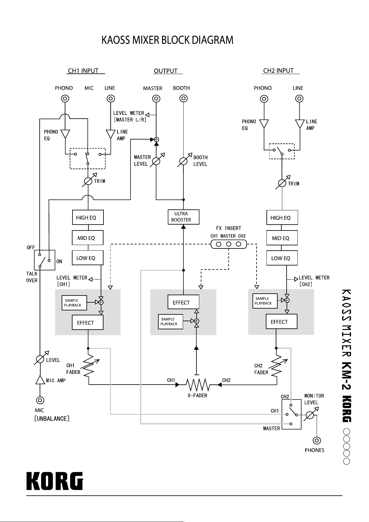
KORG INC.
15 - 12, Shimotakaido 1 - chome, Suginami-ku, Tokyo, Japan.
Printed in Japan
L02-80070-01
032001
E
F
G
J
1
 Loading...