

Page 1
Parameter guide
English
Contents
Parameters .........................................................................3
1. Program parameters ...................................................................................3
2. Timbre parameters .....................................................................................4
3. Vocoder parameters ..................................................................................13
4. Arpeggio parameters .................................................................................14
5. Edit utility parameters................................................................................. 16
6. GLOBAL parameters...................................................................................16
7. MIDI parameters ......................................................................................18
8. CV&Gate parameters ..................................................................................20
9. Foot parameters ......................................................................................20
10. UserKeyTune parameters ............................................................................21
11. EQ parameters.......................................................................................22
12. Tube parameters.....................................................................................22
13. Global utility.........................................................................................22
Effects ............................................................................23
1. What are effects.......................................................................................23
2. Effects provided by the ...............................................................................23
3. Controlling the effects ................................................................................23
4. Program effects .......................................................................................24
5. Global effects .........................................................................................28
MIDI ..............................................................................30
1. Using the with other MIDI devices (MIDI) .............................................................30
2. Channels and messages ..............................................................................32
3. Parameters transmitted and received via NRPN........................................................34
4. System exclusive messages ...........................................................................34
5. Realtime Messages....................................................................................34
6. Default control change assignments and transmission/reception (CC#Map) ...........................35
Page 2

KingKORG Parameter Guide
Thank you for purchasing the Korg KingKORG Synthesizer. To help you get the most out of your new
instrument, please read this manual carefully.
About the owner’s manual
The documentation for this product consists of the following:
- Owner’s manual (included with the instrument)
- Parameter guide (PDF)
Owner’s manual
This provides a simple explanation of the KingKORG’s main functionality. Read this
rst.
Parameter guide
This provides information about all of the KingKORG’s parameters.
Read this guide when you want to nd out what specic parameters do.
The parameter guide is structured as follows.
- Parameters
- Eects
- MIDI
You can read the parameter guide on your computer.
Abbreviations for the manuals
OM: Owner’s Manual (included with the instrument)
PG: Parameter Guide
Display indications
The values of various parameters shown in the manual are only examples;
they might not match what you see on the KingKORG’s display.
Example of notation on the main display page
GLOBAL “g15: Power O” page
In Global mode, the page name will be displayed on the top of the main display.
* All product names and company names are the trademarks or registered trade-
marks of their respective owners.
- 2 -
Page 3
KingKORG Parameter Guide Parameters
Parameters
Block diagram
TIMBRE B
TIMBRE A
Keyboard
MIC IN
This indicates a parameter that can be controlled from the panel
buttons of the instrument.
This indicates a parameter that can be controlled from the panel
konb of the instrument.
Program parameters
1.
JoyStick
VIRTUAL PATCH
Pitch
OSC1
OSC2
OSC3
MIXER FILTER AMP
Explanation of parameter icons
p01: Name
MIDI IN
Cutoff Level PAN
Modulation to Synth
LFO2 EG2
LFO1 EG1
L/R
Vocoder PRE FX MOD FX
L/R
MASTER FX
GLOBAL
TUBE EQ
REV/
DELAY
L/MONO, R
VoiceMode ................................................[Single, Layer, Split]
This parameter determines how many timbres a program will use, and how
those timbres will be allocated.
Single:
Only one timbre will be used.
OUTPUT
The KingKORG lets you assign a name of up to 12 characters to each
program.
In Program mode, the main display shows the program number and program
name.
To edit the program name
Press the PROGRAM (GLOBAL) button to switch to Program mode.
1.
Use the PAGE +/– buttons to select the Name page.
2.
Press the VALUE dial.
3.
Use the PAGE +/– buttons to move “ ” to the character that you
4.
want.
Turn the VALUE dial to select a character.
5.
Repeat steps 4–5.
6.
Press the VALUE dial to confirm the name.
7.
p02~06: Common
Here you can adjust settings that apply to the entire program.
Category .... [Synth, Lead, Bass, Brass, Strings, Piano, Key, SE/Voc,
User]
This selects the program category.
The program will be registered in the category that you select here.
For example when you’re performing, you may find it convenient to select
programs by category. For more about selecting programs by category, refer to
“Selecting by category” on page 100 of the owner’s manual.
TIMBRE A
Layer:
Two timbres will be used. When you play the keyboard, both timbres will
sound simultaneously. You can edit each timbre individually.
TIMBRE A
TIMBRE B
Split:
Two timbres will be used. You can specify a range of notes for each
timbre, and play each timbre from a different area of the keyboard. Each
timbre can be edited separately.
Split Position=When G4
TIMBRE A
Split Position
TIMBRE B
- 3 -
Page 4
KingKORG Parameter Guide Parameters
Note on
Note on
4 voice
2 voice
Timb B Ch (Timbre B MIDI channel).......................[Global, 01…16]
When the “VOIC.MODE” is set to either Layer or Multi, this parameter can be
used to set the MIDI channel for timbre 2. If you choose Global, the MIDI
channel of timbre 2 will match the global MIDI channel.
The settings of this page will be available if the “p03:Common” page
VoiceMode parameter is set to “Layer” or “Split”.
The MIDI channel for timbre A is specied by the MIDI Basic page Global Ch parameter.
TIP:
Split Key ....................................................................[C -1…G 9]
This specifies the range of notes for which each timbre will sound.
Notes below the specified note number will be sounded by timbre A, and notes
above and including the specified note number will be sounded by timbre B.
You can also easily specify the Split Key by using the keyboard. Hold down the
SHIFT/EXIT button and press the SPLIT (POSITION) to access the following
screen.
The settings on this page will apply if the “p03:Common” page VoiceMode
parameter is set to “Split”.
The previous setting
When you press a key, that key will be specified as the Split Key, and you’ll
automatically return to the previous screen. You can also select this setting by
turning the VALUE dial instead of using the keyboard.
The value you’ ll be
setting
KeyResponse ...................................................... [Norm, Shlw, Deep]
This specifies the response of the keyboard.
In addition to the conventional velocity-sensitive mode, the KingKORG’s
keyboard provides a “switch mode” that simulates the keyboard response of a
vintage synth or an actual organ. In switch mode, the response is extremely
quick and velocity is not detected, providing a playing feel that’s ideal for rapid
synth lead passages or rapidly repeated synth brass chords.
Norm (Normal):
This is the conventional response mode that provides velocity sensitivity.
Deeply-played keystrokes will be sounded with a velocity corresponding to
your playing dynamics.
Shlw (Shallow):
This is a “switch mode” in which notes are turned on or off even by
shallow keystrokes.
This mode is effective when you’re playing a legato melody, or when
playing a rapid glissando with the palm of your hand. By striking the
keyboard strongly or releasing it rapidly, you can produce the distinctive
bounce (double triggering when you release a key) that is typical of an
organ keyboard.
Deep:
This is a “switch mode” in which notes are turned on or off by deep
keystrokes.
It will feel as though the note sounds when the key reaches the bottom of
its full stroke. This mode is effective when playing crisp melodies or
repeated chords.
Assign (Voice Assign) ................................... [Mono1, Mono2, Poly]
This parameter specifies how notes will be articulated from the keyboard (or
MIDI source).
Mono1:
The timbre will play monophonically. If you continue holding down the key
that you first pressed, the EG will not retrigger when you play the second
and subsequent keys. Use this setting when you want to play legato.
Mono2:
The timbre will play monophonically. The EG will be retriggered each time
you press a key.
Poly:
The program will play polyphonically, allowing you to play chords. The
maximum polyphony is 24 voices.
EG
Mono1
Trigger
EG
Mono2
Trigger
Unison Voice ........................................................... [Off, 2, 3, 4]
Specifies the number of voices that will be stacked.
Off:
Unison is off.
2:
Unison is on; two voices will be stacked.
3:
Unison is on; three voices will be stacked.
4:
Unison is on; four voices will be stacked.
Depending on other voice-related settings, the number of voices that
you specify here may not actually be sounded.
Turning on the Unison function will limit the available polyphony.
Detune (Unison Detune) ..................................................... [00…99]
Specifies (in units of cents) the amount of detuning that will occur between the
stacked voices.
The number of voices that you specify for the Unison Voice will change the
way that detuning occurs.
The setting on this page is available if unison is on (Unison Voice set to
“2”–”4”).
99
0
Unison
Detune
99
0
Unison
Detune
Timbre parameters
2.
If the “p03:Common” page VoiceMode parameter is set to “Layer” or “Split”,
the parameters of pages s01–s80 will show the timbre that’s selected by the
TIMBRE A/B select buttons.
s01~04: Voice
These settings specify whether the timbre will play monophonically or
polyphonically, how retriggering will occur, and how the unison function will
stack multiple copies of a voice at the same pitch.
If you simultaneously press more keys than the maximum polyphony that’s specied,
TIP:
the key you pressed last will take priority.
Spread (Unison Spread) ..................................................[000…127]
Spread controls the width of the stereo spread (panning) of the stacked voices.
The stacked notes will be spread evenly, according to the number of voices
specified by the Unison Voice and the value that you specify here.
The setting on this page will be available if unison is on (Unison Voice set to
“2”–”4”).
s05~12: Pitch
These settings affect the pitch of the timbre.
The pitch of all oscillators in the timbre you’re editing will be affected
simultaneously.
Set the transpose and tuning parameters to obtain the desired pitch.
This is also where you specify the amount of pitch change that will occur when
you move the joystick in the horizontal direction (X-axis), and adjust settings
for portamento.
- 4 -
Page 5
KingKORG Parameter Guide Parameters
Transpose .........................................................................[–48…+48]
The Transpose function specifies the pitch produced by the oscillator, in
semitone units.
The range is four octaves upward or downward.
This setting is related to the pitch of the oscillators themselves; this is
not the same as the OCTAVE [UP]/[DOWN] buttons on the front panel
that change the range of notes available on the keyboard.
Detune ............................................................. [–50 cent…+50 cent]
The Detune function adjusts the pitch of the oscillator in one-cent steps.
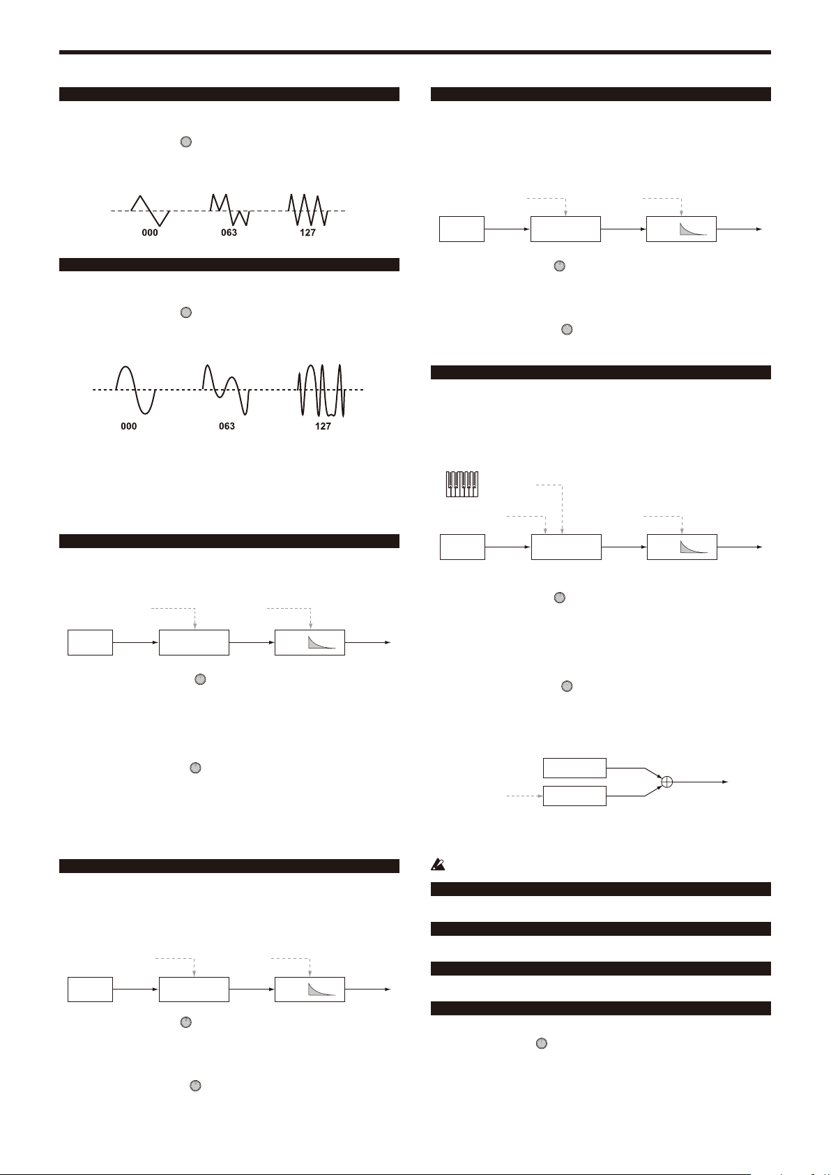
LFO2ModInt (LFO2 Modulation Intensity) ................[–63…+63]
This specifies the depth of vibrato produced by using LFO2 to modulate the
pitch of the timbre.
LFO2&JS+Y (LFO2 & Joystick+Y) ........................... [–2400…+2400]
You can use the joystick to increase or decrease the vibrato.
This specifies the depth of vibrato (in units of cents) that is produced when you
move the joystick all the way away from yourself.
The depth of the vibrato that is applied will be this setting added to the LFO2ModInt
TIP:
setting. When you take your hand off the joystick, the vibrato will be the depth specied
by LFO2ModInt.
BendRange (Pitch Bend Range) ......................................[–12…+12]
This specifies the amount of pitch change (in semitones) that will occur when
you move the joystick in the horizontal direction (X-axis).
This value is the amount of change that will occur when the joystick is moved
all the way in the horizontal direction.
Portamento .................................................................. [Off, On]
This will turn Portamento on/off (an effect that creates a smooth change in
pitch from one note to the next).
Off:
Portamento will be off.
On:
Portamento will be on. Use the Porta.Time parameter to specify the
portamento time.
Porta.Time (Portamento Time) ..................................[000…127]
This specifies how portamento will occur (the time over which the pitch change
will occur).
With a setting of “000”, there will be no portamento effect. Increasing the value
will lengthen the amount of time it takes for the portamento effect to transition
from one note to the next.
Analog Tune (Analog Tuning) ........................................[000…127]
This parameter adjusts the amount of inconsistency in the pitch of each note
that is played.
This adds a slight randomness to the pitch of each note to simulate the pitch
instability that is typical of an analog synthesizer. Higher settings produce
greater pitch variation.
s13~27: OSC1, OSC2, OSC3 (Oscillator 1, 2, 3)
Oscillators generate the basic waveform.
These settings are made individually for each of the three oscillators in each
timbre.
Type .............................................................. [Off, Saw…Mic In]
This selects the oscillator type (the basic structure of the oscillator) and its
waveform (see “Oscillator type and CONTROL 1, 2”). If you select “Off,” the
oscillator will make no sound.
Semitone ..........................................................................[–24…+24]
This specifies the amount of detune (pitch discrepancy) relative to other
oscillators in semitone steps over a range of two octaves upward or downward.
The settings on this page are available if the waveform specified by Type is
ANALOG, DWGS, or PCM.
This setting is not available if Type is set to “Mic In”.
For example if you want to use oscillator 2 as the overtone structure of oscillator 1, you
TIP:
can set this to one octave above or a fth above. If you’re using the oscillator to create
harmony, you can set this parameter to a musical third, fourth, or fth.
Tune ..............................................................................[–63…+63]
This adjusts the amount of detune relative to the other oscillators.
Settings of “±63” correspond to two octaves upward or downward, and “±48”
corresponds to one octave upward or downward. Near the “+00” setting you’ll
be able to make fine adjustments to the pitch.
The settings on this page are available if the waveform specified by Type is
ANALOG, DWGS, or PCM.
This setting is not available if Type is set to “Mic In”.
CONTROL1, CONTROL2
For each oscillator type, either one or two CONTROL parameters are provided
to control the waveform or character. The last page of each oscillator shows
the name and value of the CONTROL parameters for the Type setting that is
selected.
Some settings may produce noise.
The parameters and available values for CONTROL1 and CONTROL2
will differ depending on the selected Type. You can also refer to the
explanations below when making V.Patch (virtual patch) settings or
assigning Ctrl1 (CONTROL1) or Ctrl2 (CONTROL2) to GLOBAL MIDI
CC#Map.
Oscillator types and CONTROL 1, 2
Single oscillator
Waveform
OSC
These oscillator types provide one oscillator that outputs a basic waveform.
You can use the CONTROL1 Waveform parameter to modify the output
waveform in real time.
When using a single oscillator, CONTROL 2 is unavailable.
001: Saw
Outputs a sawtooth wave.
This waveform is suitable for the sounds that are typical of an analog
synthesizer, such as synth bass or synth brass.
CONTROL1: Waveform ................................................ [000…127]
A setting of “000” produces a pure sawtooth wave, and a setting of “127”
produces a sawtooth wave one octave higher.
002: Pulse
Outputs a pulse wave.
This waveform is suitable for electronic sounds or wind instruments.
CONTROL1: PulseWidth .............................................. [000…127]
A setting of “000” produces a pure square wave, and a setting of “127” will be
nearly inaudible since the pulse width will be minimal.
- 5 -
Page 6
KingKORG Parameter Guide Parameters
003: Triangle
Outputs a triangle wave.
This waveform has a more mild tone than a sawtooth wave or pulse wave.
CONTROL1: Waveform ................................................ [000…127]
A setting of “000” produces a pure triangle wave, and a setting of “127”
produces a triangle wave of one octave and a fifth higher (the third harmonic).
004: Sine
Outputs a sine wave.
Of the single oscillators, this waveform has the simplest overtone structure.
CONTROL1: Waveform ................................................ [000…127]
A setting of “000” produces a pure sine wave; the overtone structure will change
as you increase the value.
Noise oscillator
These oscillator types generate a noise signal.
You can choose from four types of noise, each with their own distinctive character.
Noise is used to create percussion-instrument sounds or sound effects such
as ocean waves.
007: Blue Noise
Outputs blue noise.
This noise signal has an energy distribution that increases in proportion to the
frequency. Since the low-frequency range is weaker and the high-frequency
range is stronger, it has a harder-edged character than white noise.
The name comes from the fact that light of this frequency distribution appears light blue.
TIP:
HPF Cutoff Noise Decay
HPFNoise EG
CONTROL1: HPF Cutoff ............................................... [000…127]
Adjusts the low-frequency content of the noise.
Increasing this value will attenuate the low-frequency range, producing a
harder sound.
CONTROL2: Noise Decay .............................................[000…127]
Adjusts the decay speed of the noise.
008: Res. Noise
Outputs resonance noise.
This contains narrow-band mid-frequency noise. You can use it to create noise
similar to the noise that can be heard from a pocket radio. Since the frequency
band will change depending on the key you press, this has a sense of pitch
that is not produced by the other noise oscillators, allowing you to use it for
performing.
(KBD Track)
Resonance Noise Decay
005: White Noise
Outputs white noise.
This contains equal energy at all frequencies from low to high. It is the basic
and the most frequently-used noise waveform.
Decimator Fc Noise Decay
Noise
Decimator
EG
CONTROL1: Decimator Fc ........................................... [000…127]
Adjusts the roughness of the noise.
Low values produce conventional white noise; raising the value will produce
increasingly rougher noise that is distinctive of digital technology. This is useful
when creating “retro-sounding” noises such as those typical of early video
games.
CONTROL2: Noise Decay .............................................[000…127]
Adjusts the decay speed of the noise.
Low values produce a fast decay. At a setting of “127” there will be no decay;
the sound will continue at a fixed level until you release the key.
The EG2-Amp settings also affect the volume; set those parameters in conjunction with
TIP:
this parameter.
006: Pink Noise
Outputs pink noise.
This noise signal has an energy distribution that decreases in proportion to the
frequency. Since the low-frequency range is stronger and the high-frequency
range is weaker, it has a more mild character than white noise.
The name comes from the fact that light of this frequency distribution appears pink.
TIP:
LPF Cutoff Noise Decay
LPFNoise
EG
CONTROL1: LPF Cutoff ................................................ [000…127]
Adjusts the high-frequency portion of the noise.
As you decrease this value the high-frequency content will diminish
correspondingly, producing a more mild sound.
CONTROL2: Noise Decay .............................................[000…127]
Adjusts the decay speed of the noise.
Noise
BPF
EG
CONTROL1: Resonance ............................................... [000…127]
Boosts the mid-frequency range of the noise.
Increasing this value will increase the intensity of the boost, giving the noise a
more distinctive character.
By increasing the value even further, you can obtain a unique sound
reminiscent of blowing strongly through a pipe.
CONTROL2: Noise Decay .............................................[000…127]
Adjusts the decay speed of the noise.
Dual oscillator
OSC A
Detune
These oscillator types stack two oscillators, each outputting a basic waveform,
and mix the output.
By varying the pitch of one oscillator you can easily obtain a unison effect.
If you’ve selected a dual oscillator, CONTROL 2 is not available.
009: Dual Saw
Outputs two sawtooth waves.
010: Dual Square
Outputs two square waves.
011: Dual Tri.
Outputs two triangle waves.
012: Dual Sine
Outputs two sine waves.
CONTROL1: Detune ..................................................... [–63…+63]
This adjusts the pitch of oscillator B.
Settings of “±63” correspond to ±2 octaves, settings of “±48” correspond to ±1
octave, and a setting of “+00” is the same pitch as oscillator A.
OSC B
- 6 -
Page 7
KingKORG Parameter Guide Parameters
Unison oscillator
OSC A
OSC B
OSC C
Detune
OSC D
OSC E
These oscillator types stack five oscillators, each outputting a basic waveform,
and mix the output.
You can create thick, rich sounds by playing just a single note.
If you’ve selected a unison oscillator, CONTROL 2 is not available.
013: Unison Saw
Outputs two sawtooth waves.
014: Unison Squ.
Outputs two square waves.
015: Unison Tri.
Outputs two triangle waves.
016: Unison Sine
Outputs sine waves.
CONTROL1: Detune ..................................................... [000…127]
This detunes the pitch of the five oscillators.
Increasing this value will broaden the pitch difference between the oscillators,
creating a thicker sound.
Ring oscillator
OSC A
Mod Pitch
These oscillator types multiply waveforms of differing frequencies, adding sum
and difference overtones that do not exist in the original sound.
You can use these to produce bell-like or metallic sounds.
If you’ve selected a ring oscillator, CONTROL 2 is not available.
OSC B
RING MOD
021: Ring Saw
Multiplies a sawtooth wave by another sawtooth wave, and outputs the result.
022: Ring Square
Multiplies a square wave by another square wave, and outputs the result.
023: Ring Tri.
Multiplies a triangle wave by another triangle wave, and outputs the result.
024: Ring Sine
Multiplies a sine wave by another sine wave, and outputs the result.
CONTROL1: Mod Pitch ................................................ [–63…+63]
This adjusts the pitch of oscillator B (modulator).
Settings of “±48” correspond to ±1 octave; at a setting of “+00” the pitch will be
the same as oscillator A.
Cross modulation oscillator
Sync oscillator
Mod Pitch = 0
OSC A
Phase Reset
Mod Pitch
These oscillator types forcibly reset the phase of the oscillator B waveform
(slave) at each cycle of the oscillator A (master) waveform, producing a
distinctive overtone structure.
If you’ve selected a sync oscillator, CONTROL 2 is not available.
OSC B
017: Sync Saw
Outputs a modulated sawtooth wave.
018: Sync Square
Outputs a modulated square wave.
019: Sync Tri.
Outputs a modulated triangle wave.
020: Sync Sine
Outputs a modulated sine wave.
CONTROL1: Mod Pitch ................................................[000…127]
This adjusts the pitch of oscillator B (slave waveform).
A setting of “32” is +1 octave, and a setting of “64” is +2 octaves.
Mod Pitch = 8
Mod Pitch = 47
Mod Depth
Mod Pitch
These oscillator types use the output waveform of oscillator B (modulator) to
modulate the frequency of oscillator A (carrier), producing a complex overtone
structure. This lets you apply modulation at a higher frequency than an LFO.
OSC B
CROSS MOD
OSC A
025: XMod Saw
Outputs a modulated sawtooth wave.
026: XMod Square
Outputs a modulated square wave.
027: XMod Tri.
Outputs a modulated triangle wave.
028: XMod Sine
Outputs a modulated sine wave.
CONTROL1: Mod Depth ...............................................[000...127]
This adjusts the depth of cross modulation.
CONTROL2: Mod Pitch .................................................[–63...+63]
This adjusts the pitch of oscillator B (modulator).
Settings of “±63” correspond to ±2 octaves, settings of “±48” correspond to ±1
octave, and “+00” is the same pitch as oscillator 1.
Variable phase modulation oscillator
Mod Depth
Mod Harmonics
These oscillator types use the output waveform of oscillator B (modulator) to
modulate the phase of oscillator A (carrier), producing a complex overtone
structure.
This lets you apply modulation at a higher frequency than an LFO. Unlike
cross modulation, OSC B will modulate the phase at precise integer multiple
frequencies (Mod Harmonics) of OSC A, and therefore pulsing will not occur in
the waveform.
OSC B
VPM
- 7 -
OSC A
Page 8
KingKORG Parameter Guide Parameters
029: VPM Saw
Outputs a modulated sawtooth wave.
030: VPM Square
Outputs a modulated square wave.
031: VPM Tri.
Outputs a modulates triangle wave.
032: VPM Sine
Outputs a modulated sine wave.
CONTROL1: Mod Depth ...............................................[000...127]
This adjusts the depth of the VPM (Variable Phase Modulation) effect.
CONTROL2: Mod Harm(Mod Harmonics) .................. [0.5, 1...32]
This specifies the pitch of oscillator B (modulator) as a harmonic multiple of
oscillator A (carrier).
DWGS oscillator
Mod Depth
Detune
These oscillator types produce the simple DWGS (Digital Waveform Generator
System) waveforms found on digital synthesizers such as the Korg DW-8000.
You can generate complex overtones by using VPM (Variable Phase
Modulation) to modulate the waveform.
DWGS A
DWGS B
033-096: DWGS
These are DWGS waveforms from digital synthesizers.
CONTROL1: Detune ......................................................[000...127]
Detunes the relative pitch of the two DWGS oscillators.
Higher values will broaden the pitch difference, creating modulation that makes
the sound richer.
CONTROL2: Mod Depth ..............................................[000…127]
Adjusts the depth of the VPM effect for the DWGS waveform.
PCM oscillator
These oscillator types produce PCM waveforms of acoustic instruments or
digital synthesizers.
097-126: PCM
These are PCM waveforms of acoustic instruments and digital synthesizers.
If you’ve selected a PCM oscillator, CONTROL 1 and CONTROL 2 are
not available.
MIC IN oscillator
Gain
Mic Input
This lets you use the signal from the rear panel mic jack as the oscillator
waveform.
You can apply the filter, amp, and effects to this audio signal.
If you’re using the audio input from the mic jack, pitch-related parameters
are not available.
If you’ve selected the MIC IN oscillator, CONTROL 2 is not available.
127: Mic In
Outputs the signal from the rear panel mic jack.
CONTROL1: Gain .........................................................[–63…+63]
This adjusts the level of the signal from the mic jack.
At a value of “+00” the input signal will be unchanged (Unity Gain).
If the peak LED lights up, you should also adjust the front panel MIC
LEVEL knob until the signal is no longer peaking.
Oscillator list
Oscillator types 001–032 are excellent analog modeling oscillators. When you
select one of these, the ANALOG LED will light up below the OSCILLATOR
sub-display.
No. Type Control1 Control2
001 Saw Waveform —
002 Pulse PulseWidth —
003 Triangle Waveform —
004 Sine Waveform —
005 White Noise Decimator Fc Noise Decay
006 Pink Noise LPF Cutoff Noise Decay
007 Blue Noise HPF Cutoff Noise Decay
008 Res. Noise Resonance Noise Decay
009 Dual Saw Detune —
010 Dual Square Detune —
011 Dual Tri. Detune —
012 Dual Sine Detune —
013 Unison Saw Detune —
014 Unison Squ. Detune —
015 Unison Tri. Detune —
016 Unison Sine Detune —
017 Sync Saw Mod Pitch —
018 Sync Square Mod Pitch —
019 Sync Tri. Mod Pitch —
020 Sync Sine Mod Pitch —
021 Ring Saw Mod Pitch —
022 Ring Square Mod Pitch —
023 Ring Tri. Mod Pitch —
024 Ring Sine Mod Pitch —
025 XMod Saw Mod Depth Mod Pitch
026 XMod Square Mod Depth Mod Pitch
027 XMod Tri. Mod Depth Mod Pitch
028 XMod Sine Mod Depth Mod Pitch
029 VPM Saw Mod Depth Mod Harm
030 VPM Square Mod Depth Mod Harm
031 VPM Tri. Mod Depth Mod Harm
032 VPM Sine Mod Depth Mod Harm
033–096
097–126
127 Mic In Gain —
DWGS Detune Mod Depth
PCM — —
- 8 -
Page 9
KingKORG Parameter Guide Parameters
s28~30: Mixer
This is where you can adjust the volume balance of oscillator 1, oscillator 2,
and oscillator 3. These settings will determine the input level to the filter.
OSC1Level .................................................................... [000…127]
Sets the output level of oscillator 1.
OSC2Level .................................................................... [000…127]
Sets the output level of oscillator 2.
OSC3Level .................................................................... [000…127]
Sets the output level of oscillator 3.
s31~38: Filter
The filter shapes the character of the sound by reducing or boosting specified
frequency regions in the sound generated by the oscillator.
You can select a filter type and adjust the cutoff frequency to shape the sound,
or dynamically modulate the filter as a performance effect.
Three types of filters are provided: low pass filters which make the tone milder
by reducing the high frequencies, high pass filters which make the tone
brighter by reducing the low frequencies, and band pass filters which reduce
both the high and low frequency regions to leave only a specific frequency
band.
You can choose from a total of 18 types, including not only standard analog
modeling filters but also modeling types that reproduce the distinctive filters
that can be found on classic synthesizers of the past.
Type (Filter Type) ............................. [LPF King 1…BPF+ King]
Selects the filter type.
The characteristics of each type are described below. To experience the
differences between the filter types, try changing the resonance and cutoff
while you play.
Product
Modeling:
Selfoscillating
Fixed Gain: Even when you vary the resonance, these
LPF Low Pass Filter
Filter Type Description
01 LPF King 1 A standard four-pole analog low pass filter. Compared
02 LPF King 2
03 LPF MG
04 LPF P5
05 LPF OB A low pass filter that has the characteristics of the filter
06 LPF MS-20
These filters model the filters of a synthesizer
of the past.
These filters simulate the self-oscillation that
occurred at the cutoff frequency when the
resonance was raised nearly to the maximum.
filters maintain a fairly consistent volume in the
frequency region that is not being cut by the
filter (→ p.10).
to a two-pole filter, this attenuates the high-frequency
region more steeply.
A standard two-pole analog low pass filter. It gently cuts
the high-frequency region, producing a warmer sound
A low pass filter that has the characteristics of the filter
from a famous monophonic analog synthesizer of the
1970s. It is ideal for lead or bass sounds.
A low pass filter that has the characteristics of the filter
from a famous five-note polyphonic synthesizer that
appeared at the end of the 1970s and was widely used
in the new wave music of the 1980s.
from an analog monophonic synthesizer expander
module of the second half of the 1970s.
A low pass filter that models the filter from Korg’s
classic MS-20 analog synthesizer. This simulates the
original’s lo-fi sense of noise and distortion, as well as
the rough self-oscillation that occurred when the
resonance was increased.
.
Filter Type Description
07 LPF Acid
This adds distortion to the low pass filter from a
famous compact bass synthesizer that was widely
used in styles such as Acid House in the second half
of the 1980s. High resonance settings will cause the
peaks to distort, adding distinctive overtones.
HPF High Pass Filter
Filter Type Description
08 HPF King A standard analog high pass filter.
09 HPF P5
10 HPF OB
11 HPF MS-20
12 HPF Acid
A high pass filter that has the pure self-oscillation of
LPF P5. This is a hypothetical modeling filter that did
not exist on the original unit.
A high pass filter that has the noise and resonance
characteristics of the LPF OB.
A high pass filter that models the filter from the MS-20,
as with the LPF MS-20.
This model connects distortion to a high pass filter with
the resonance distortion characteristics of LPF Acid.
BPF Band Pass Filter
Filter Type Description
13 BPF King A standard analog band pass filter.
14 BPF P5
15 BPF OB
16 BPF MS-20
17 BPF Acid
18 BPF+ King This filter mixes the original sound with the output of a
Cutoff ............................................................................[000...127]
This sets the cutoff frequency.
Increasing this value will raise the cutoff frequency.
“CUTOFF” can be varied by time-variant changes produced by EG1-Filter, by
keyboard playing dynamics (velocity), and by note location (keyboard tracking).
A band pass filter that can produce the pure selfoscillation of LPF P5. This is a hypothetical modeling
filter that did not exist on the original unit.
A band pass filter with the noise and resonance
characteristics of the LPF OB.
A band pass filter that has the lo-fi and distortion
characteristics of LPF MS-20. This is a hypothetical
modeling filter that did not exist on the original MS-20.
An LPF MS-20 and HPF MS-20 are connected in
series.
This model connects distortion to a band pass filter
that has the resonance distortion characteristics of
LPF Acid. This is a hypothetical modeling filter that did
not exist on the original unit.
standard band pass filter. It lets you obtain the
distinctive tone of a band pass filter without losing the
high- and low-frequency nuances of the original sound.
- 9 -
Page 10
KingKORG Parameter Guide Parameters
Fixed Gain not supported
Fixed Gain supported
Low resonance value High resonance value
Low resonance value High resonance value
Resonance .....................................................................[000...127]
This sets the resonance of the filter.
Boosts the volume in the region of the frequency specified by Cutoff, adding a
distinctive character to the sound. Higher values will produce a greater effect.
LPF
HPF
BPF
Low resonance value
For filter types that simulate Fixed Gain, higher resonance settings will produce
a louder volume compared to other types.
Depending on the cutoff frequency or the input audio, increasing this
value may cause distortion.
High resonance value
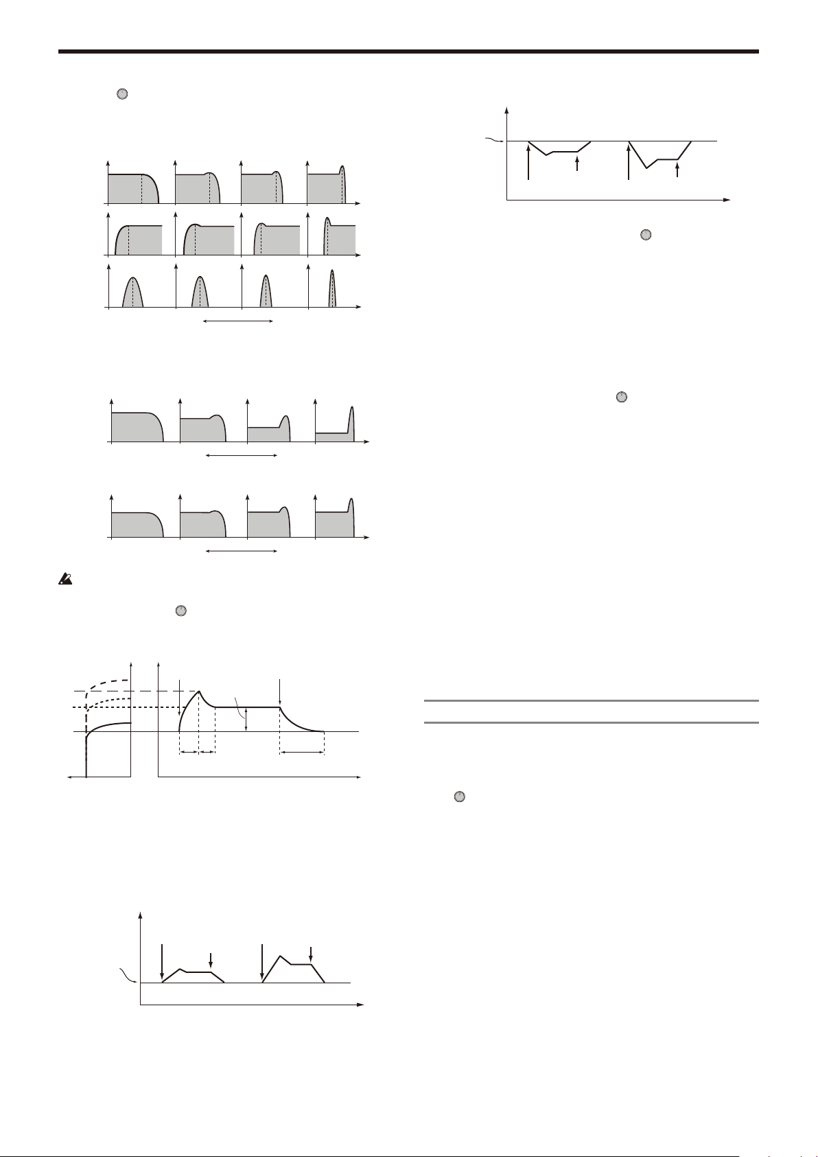
EG1Int (EG1 Intensity) ................................................[–63…+63]
This specifies how time-variant modulation from the EG1-Filter will be applied
to the cutoff frequency.
Note on
Sustain Level
Note off
Cutoff
Cutoff frequency
specified by
“Cutoff”
Int = –32
Note on
Note off
Int = –63
Note on
Int = 0
Note off
Time
LFO1ModInt (LFO1 Modulation Intensity) ................[–63…+63]
Specifies the depth of the wah effect produced by using LFO1 to modulate the
cutoff frequency.
LFO1&JS-Y ........................................................................[–63…+63]
You can use the joystick to increase or decrease the wah effect. This
parameter specifies the depth of the wah effect that will be obtained when you
move the joystick all the way toward yourself.
The wah effect will be the depth specied by this parameter plus the LFO1ModInt
TIP:
setting. When you release your hand from the joystick, the effect will be at the depth
specied by LFO1ModInt.
KeyTrack (Keyboard Tracking/ Filter) ..................[–2.00…+2.00]
Varies the cutoff frequency by keyboard tracking (the keyboard position you
play).
For example if you can get the sound you want at the C4 key, but the tone
becomes too mild as you play above or below that key, you can use keyboard
tracking to raise the cutoff frequency to obtain the desired sound.
Positive (+) values cause the cutoff frequency to rise as you play above the C4
key, and fall as you play below the C4 key.
Negative (–) values cause the cutoff frequency to fall as you play above the C4
key, and rise as you play below the C4 key.
If this value is “+1.00” the change in cutoff frequency will be proportionate to the pitch. If
TIP:
this value is “+0.00” no change will be produced by keyboard tracking.
Keyboard tracking works on the pitch that is modied by pitch bend and transpose.
TIP:
VeloSens (Velocity Sensitivity) ......................................[–63…+63]
This specifies how the cutoff frequency will be affected by velocity (keyboard
playing dynamics).
Positive (+) values cause the cutoff frequency to rise as you play the keyboard
more strongly.
Negative (–) values cause the cutoff frequency to fall as you play the keyboard
more strongly.
s39~42: Amp (Amplifier)
Cutoff
Attack
Decay
Time
Time
The EG1-Filter varies the cutoff frequency over time, causing the tone to
change.
For example, you can use this to create a sound that gradually begins to
brighten when you press the key, and then gradually becomes darker.
“EG1-Filter INT” parameter specifies the depth (sensitivity) to which the
EG1-Filter will affect the cutoff frequency. With a setting of 0, the EG1-Filter
will not affect the cutoff frequency. Increasingly positive (+) settings will allow
the EG1-Filter to have a correspondingly greater effect on the cutoff frequency.
Cutoff
Cutoff frequency
specified by
“Cutoff”
Increasingly negative (–) settings will allow a correspondingly greater effect in
the opposite direction.
Int = +32
Note on
Note off
Int = +63
Note on
Release
Time
Note off
Time
Int = 0
Time
Here you can adjust various settings such as the volume and panning of the
timbre.
The sound that is created by passing through the oscillator and filter is
amplified by the amp.
Level ............................................................................. [000…127]
This adjusts the volume of the timbre.
Pan (Panpot) .................................................... [L63…Center…R63]
This adjusts the location of the sound in the stereo field. L63 is far left, CNT is
center, and R63 is far right.
Punch Level ......................................................................[000…127]
This adjusts an effect that boosts the volume of the timbre’s output signal only
during the attack. Higher settings will emphasize the attack.
KeyTrack (Keyboard Tracking/Amp) ..............................[–63…+63]
This specifies how keyboard tracking will affect the volume.
With positive (+) settings, the volume will increase as you play above the C4
note on the keyboard, and will decrease as you play below C4. With negative
(–) settings, the volume will decrease as you play above the C4 note on the
keyboard, and will increase as you play below C4.
Keyboard Track functions according to the pitch that is controlled by pitch bend, and
TIP:
transpose. It is not affected by pitch changes produced by vibrato or Virtual Patch.
- 10 -
Page 11
KingKORG Parameter Guide Parameters
Organ
s43~47: EG1-Filter
Here you can adjust settings for the filter EG that causes the sound to vary
over time.
Here you can adjust settings for the filter EG, which creates time-varying
changes in the tonal character. Specify the EG settings in these pages, and
use the EG1Int parameter (→ p.10) to specify how deeply the filter will be
affected by the EG. Use the ADSR (Attack, Decay, Sustain, Release)
parameters to create the desired curve of tonal change.
By assigning EG1-Filter as the source for a virtual patch, you can use it to modulate
TIP:
parameters other than the lter (→ p.12).
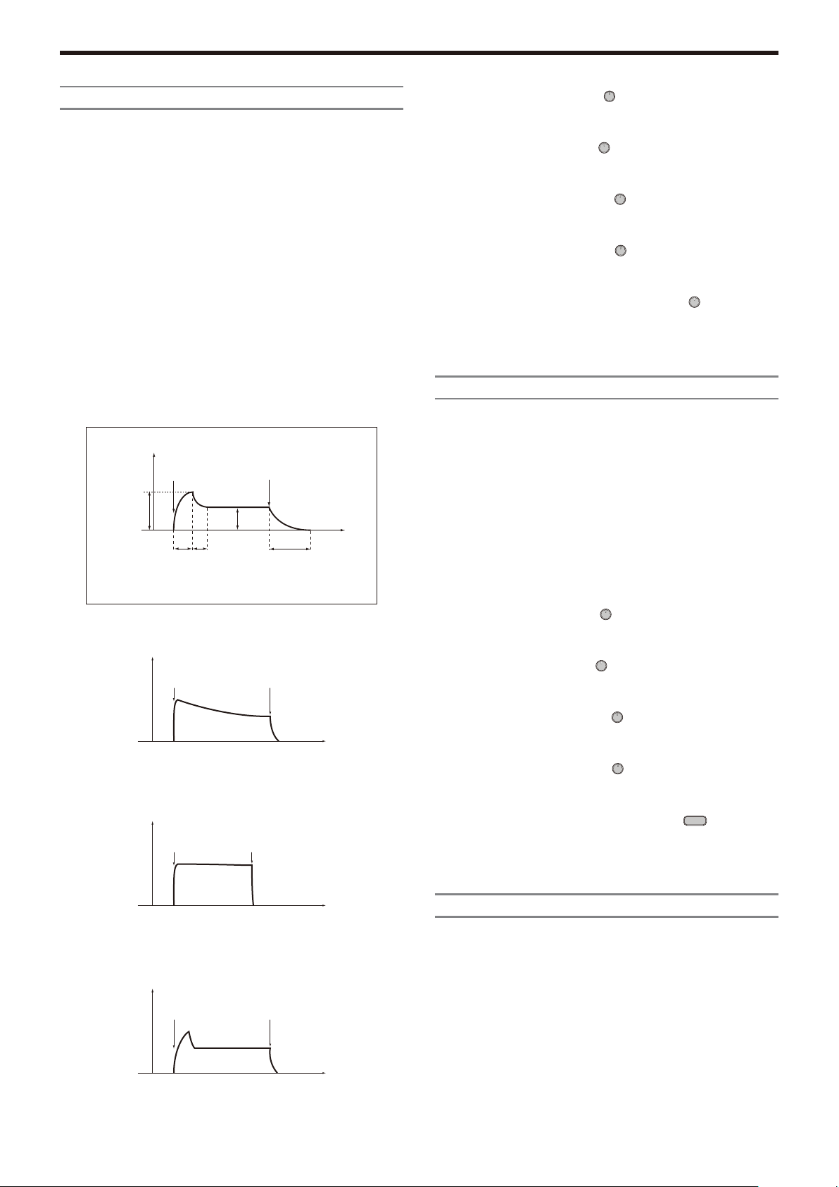
EG (Envelope Generator)
To a significant extent, each sound has its own distinctive volume curve. For
example when you play a note on a piano, the note begins at the maximum
volume, and gradually diminishes. When you release your finger from the key,
the sound will disappear quickly with a brief decay. Volume curves such as this
are an important aspect of how we identify the sound of a specific instrument.
This type of change also occurs in the tone and pitch, as well as in the volume.
On a synthesizer, this type of change is produced by an EG. The KingKORG
has dedicated EGs for the filter and for the amp. However since these EGs
can be used as Virtual Patch sources, you are also free to use them to vary
the pitch or numerous other aspects of the sound. Some example amp EG
settings are illustrated below.
EG
Level
Note on
Note off
Attack (Attack Time/EG1-Filter) ................................. [000…127]
This specifies the time from note-on (when the key is pressed) until the attack
level (maximum value of the envelope) is reached.
Decay (Decay Time/EG1-Filter) ..................................[000…127]
This specifies the time from when the attack level is reached until the sustain
level (SUSTAIN) is reached.
Sustain (Sustain Level/EG1-Filter) .............................[000…127]
This specifies the cutoff frequency that will be maintained after the decay time
has elapsed, until you release the key.
Release (Release Time/EG1-Filter) ............................. [000…127]
This specifies the time from note-off (when the key is released) until the level
reaches 0.
LevelVelInt (Level Velocity Intensity/EG1-Filter) .....[–63…+63]
This specifies how your keyboard velocity (playing strength) will affect the
amplitude of EG1-Filter. Higher settings of this parameter will allow changes in
your keyboard velocity to produce greater differences in EG1-Filter amplitude.
s48~52: EG2-Amp
Here you can adjust the settings for the AMP EG, which applies time variant
changes to the volume. Using the AMP EG settings, you can make the volume
change as time passes. Create the desired volume curve by adjusting the
ADSR parameters; ATTACK, DECAY, SUSTAIN, RELEASE.
You can use EG2 as a Virtual Patch source to modulate parameters other than volume
TIP:
(→ p.12).
Attack Level
Piano
Level
0
Level
0
Strings
Level
0
0
[1]
[1]: Attack Time [3]: Sustain Level
[2]: Decay Time [4]: Release Time
Note on
Attack: 0 Sustain: 0
Decay: 100 – 127 Release: 5 – 25
Note on
Attack: 0 Sustain: 127
Decay: 0 Release: 0
Note on
Attack: 40 Sustain: 75
Decay: 50 Release: 50
[3]
[2]
Note off
Note off
Note off
EG1 and EG2
Time
[4]
Time
Time
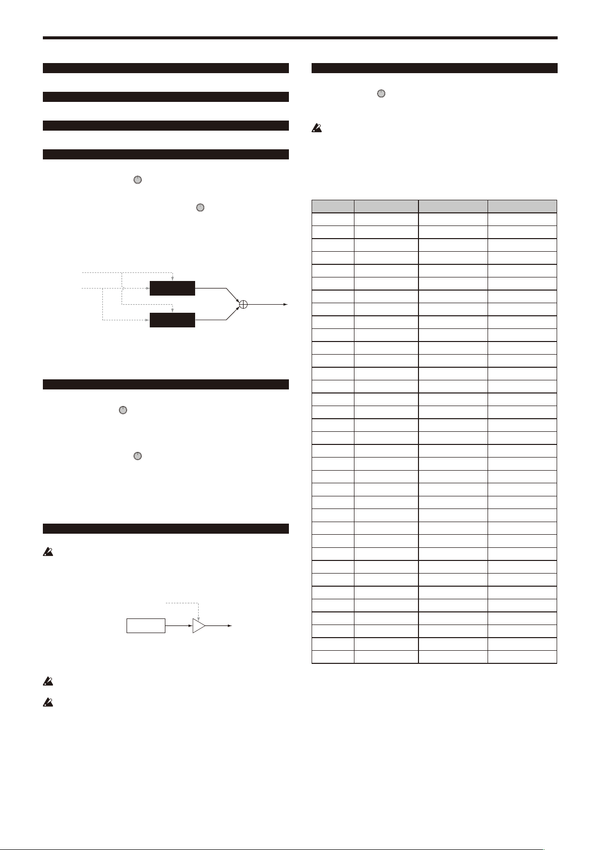
As the EG1-Filter changes the cutoff frequency, the tone will change. However,
the overall character of the sound will also depend on the volume changes that
are produced by the EG2-Amp. For example, setting a long decay for the Filter
EG (EG1) will produce a different sound depending on how the decay is set in
the Amp EG (EG2). It’s a good idea to be aware of both the EG1-Filter settings
and the EG2-Amp settings as you’re editing.
Attack (Attack Time/EG2-Amp) .................................. [000…127]
This specifies the time from note-on (when the key is pressed) until the attack
level (maximum value of the envelope) is reached.
Decay (Decay Time/EG2-Amp) ...................................[000…127]
This specifies the time from when the attack level is reached until the sustain
level (SUSTAIN) is reached.
Sustain (Sustain Level/EG2-Amp) .............................. [000…127]
This specifies the volume that will be maintained after the decay time has
elapsed, as long as you continue holding the key.
Release (Release Time/EG2-Amp) .............................. [000…127]
This specifies the time from note-off (when the key is released) until the level
reaches 0.
LevelVelInt (Level Velocity Intensity/EG2-Amp)
This specifies how your keyboard velocity (playing strength) will affect the
EG2-Amp. Higher settings of this parameter will allow changes in your
keyboard velocity to produce greater differences in EG amplitude.
...[–63…+63]
s53~62: LFO1, LFO2
Each timbre contains two LFOs. An LFO produces a cyclic change that can be
used to modulate the pitch, tone, or volume of the sound.
By assigning LFO1 or LFO2 as sources for a virtual patch, you can use them to modulate a
TIP:
variety of parameters (→ p.12).
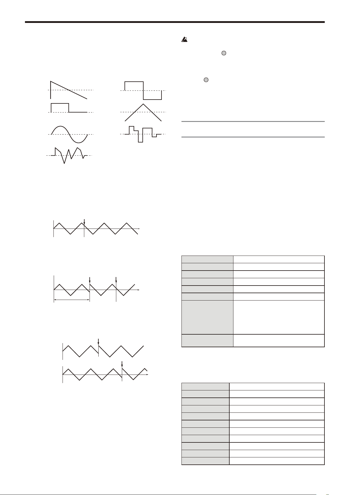
LFO (Low Frequency Oscillator)
The LFO (Low Frequency Oscillator) is an oscillator with a low (slow) rate.
It is typically used to apply a vibrato effect (use LFO to raise and lower the
pitch), wah effect (use LFO to raise and lower the cutoff frequency), or tremolo
Time
effect (use LFO to raise and lower the volume).
You can select LFO as a Virtual Patch source, select the desired parameter as
the destination, and apply modulation to produce various effects. The
KingKORG provides special parameters that can be modulated from an LFO.
For LFO1, these parameters are the “Filter” page parameters LFO1ModInt and
- 11 -
Page 12
KingKORG Parameter Guide Parameters
Triangle
Sine
Saw
Square
Square+
S&H
Amplitude changes
irregularly
(Sample & Hold)
Random
Change linearly
with random values
Note on
Note on Note on
Note on
LFO1&JS-Y. For LFO2, they are the “Pitch” page parameters LFO2ModInt and
LFO2&JS+Y.
Wave (LFO1) ....................... [Saw, Square, Triangle, S&H, Random]
Wave (LFO2) ............................[Saw, Square+, Sine, S&H, Random]
Selects the LFO waveform.
KeySync ..............................................................[Off, Timbre, Voice]
This specifies how the LFO will be applied to a voice when note-on occurs.
Off:
The LFO phase will not be reset when note-on occurs.
Timbre:
The phase of the LFO will be reset by the first note-on that occurs from a
condition of no keys being held; it will not be reset for subsequently played
voices.
Note all off
Voice:
The LFO phase will be reset at each note-on, and modulation of differing
phases will apply to each voice.
1VOICE
Note on
2VOICE
TempoSync........................................................................... [Off, On]
Specifies whether the LFO cycle will be synchronized to the internal tempo or
to an external MIDI Clock.
Off:
The LFO will not be synchronized. It will function at the frequency
specified by the Freq. parameter.
On:
The LFO will be synchronized to the [TEMPO] knob or to MIDI Clock
messages from an external device.
If TempoSync is “On,” selecting “LFO1Freq” or “LFO2Freq” as a Dest in
the “V.Patch1–6” page will have no effect.
Freq. (Frequency) .................................... [000.01Hz…100.00Hz]
This specifies the frequency of the LFO. Increasing this value will result in a
faster frequency.
The settings in this page are available if TempoSync is “Off”.
SyncNote ................................................................[8meas…1/64]
This specifies the LFO rate as a ratio of the Tempo setting in the “Arp” page.
The length (note value) you specify here will be one cycle of the LFO.
For example if this is set to 1/4, one cycle of the LFO will occupy one beat. If
this is set to 3/4, one cycle of the LFO will occupy three beats.
The settings in this page are available if TempoSync is “On”.
s63~s80: V.Patch1, V.Patch2, V.Patch3,
V.Patch4,V.Patch5, V.Patch6
To let you create even more sophisticated sounds, the KingKORG provides six
virtual patches. Each patch consists of three parameters: the source of the
modulation (Src), the destination to which that modulation will apply (Dest),
and the intensity of that modulation effect (Int). You can produce a variety of
changes in the sound by combining these parameters. For example by setting
Src to “LFO2”, “Dest” to “Cutoff”, and specifying the amount of effect using Int,
you can produce a cyclic change in tone (wah effect) produced by LFO2.
Virtual Patch
On modular analog synthesizers, the input or output of each module (oscillator, filter, amp, EG, LFO, and other controllers) could be connected
(“patched”) by a patch cord to any other module as desired, allowing you a
great deal of freedom in creating the sound. The Korg MS Series (MS-20,
MS-50, MS-10, etc.) went on sale in 1978 and featured this type of patching.
The KingKORG lets you perform this patching “virtually” (i.e., with-out using
physical patch cords), so you can assign sources such as EG or LFO to the
most important parameters (destinations).
Src (Source) ..................................................................[EG1…MIDI3]
Selects the signal (source) that will be the source of modulation.
EG1, EG2 EG1, EG2
LFO1, LFO2 LFO1, LFO2
Velocity Keyboard velocity (playing dynamics).
PitchBend Pitch bend (joystick: X-axis left/right)
JS+Y
JS-Y Modulation (joystick: Y-axis toward yourself)
KeyTrack
MIDI1, MIDI2, MIDI3
Dest(Destination) ....................................................[Off…R/D Time]
This selects the parameter (destination) that will be controlled by the
modulation. For example if you select Tune, modulation will be applied to the
overall pitch of the timbre.
Off
Pitch The pitch of the entire timbre.
Portamento The Pitch page “Porta.Time”.
Osc1Tune The Osc1 page “TUNE”.
Osc2Tune The Osc2 page “TUNE”.
Osc3Tune The Osc3 page “TUNE”.
Osc1Ctr1 The Osc1 page “Control1”.
Osc2Ctr1 The Osc2 page “Control1”.
Osc3Ctr1 The Osc3 page “Control1”.
Osc1Ctr2 The Osc1 page Control2
Osc2Ctr2 The Osc2 page Control2
Modulation (joystick: Y-axis away from yourself)
Keyboard tracking (position).
Keyboard tracking works according to the
pitch as controlled by pitch bend, transpose,
and modulation sequencer. It does not reflect
pitch changes produced by vibrato or virtual
patching.
The function specified for the [MIDI Ctrl] page
parameters “MIDI1,” “MIDI2,” or “MIDI3”.
—
- 12 -
Page 13

KingKORG Parameter Guide Parameters
Osc3Ctr2 The Osc3 page Control2
Osc1Level The Mixer page Osc1Level
Osc2Level The Mixer page Osc2Level
Osc3Level The Mixer page Osc3Level
Cutoff The Filter page Cutoff
Resonance The Filter page Resonance
FcEG1Int The Filter page EG1Int
FcKeyTrk The Filter page KeyTrack
EG1Attack The EG1-Filter page Attack
EG1Decay The EG1-Filter page Decay
EG1Sustain The EG1-Filter page Sustain
EG1Release The EG1-Filter page Release
EG2Attack The EG2-Amp page Attack
EG2Decay The EG2-Amp page Decay
EG2Sustain The EG2-Amp page Sustain
EG2Release The EG2-Amp page Release
LFO1Freq The LFO1 page Freq.
LFO2Freq The LFO2 page Freq.
AmpLevel The Amp page Level
Panpot The Amp page Pan
Patch1Int The V.Patch1 page Int
Patch2Int The V.Patch2 page Int
Patch3Int The V.Patch3 page Int
Patch4Int The V.Patch4 page Int
Patch5Int The V.Patch5 page Int
Patch6Int The V.Patch6 page Int
Pre Drive DRIVE/FREQ knob of PRE FX
Mod Depth DEPTH knob of MOD FX
Mod Speed SPEED knob of MOD FX
R/D Depth DEPTH knob of REV/DELAY
R/D Time TIME knob of REV/DELAY
Int (Intensity) ...................................................................[–63…+63]
Specifies the depth of the effect produced by the modulation source. With a
setting of “+00”, there will be no modulation.
Setting example for “SOURCE” and “DEST”
Src Dest
EG1/EG2 Pitch The EG1 or EG2 will vary the pitch of
EG1/EG2 Panpot
LFO1/LFO2 Pitch Vibrato will apply at the rate of LFO1 or
LFO1/LFO2 Cutoff Wah will be applied at the LFO1 or
LFO1/LFO2 AmpLevel Tremolo will be applied at the LFO1 or
LFO1/LFO2 Panpot Auto pan will be applied at the LFO1 or
Velocity AmpLevel Velocity (keyboard playing strength) will
KeyTrack Panpot Keyboard position will gradually change
PitchBend Panpot Joystick operation will move the sound
the entire timbre over time.
The EG1 or EG2 will vary the pan over
time. By setting two patches to Patch#Int
settings with the opposite (+/–) value you
can create more complex panning.
LFO2.
LFO2 frequency.
LFO2 frequency.
LFO2 frequency.
affect the volume.
the pan; lower notes at the left, and
higher notes at the right.
left or right.
Vocoder parameters
3.
We recommend that you edit the vocoder parameters while looking at the
vocoder block diagram (OM: p.17).
v01: Vocoder
Vocoder SW (Vocoder Switch) .................................... [Off, On]
This switches the Vocoder function on/off.
Off:
The vocoder function will be off. The front panel VOCODER button will be
unlit, and the program will not use the vocoder.
On:
The vocoder function will be on. The front panel VOCODER button will be
lit, and the program will use the vocoder. You’ll be able to select and edit
the vocoder parameter pages (“v02: Voc.Carrier” – “v18: Voc.Amp”).
v02~03: Voc.Carrier (Vocoder Carrier)
On these pages you’ll specify the input level for the carrier, the original signal
where the vocoder effect is applied.
Timb A Level (Timbre A Level) ........................................[000…127]
This specifies the output level of Timbre A (carrier).
Timb B Level (Timbre B Level) ........................................[000…127]
This specifies the output level of Timbre A.
v04~08: Voc.Modultr (Vocoder Modulator)
On this page you can adjust settings for the modulator, which applies its
character to the carrier audio.
As the modulator, you can input either the signal from the mic (Input) or timbre
B.
AudioSrc (Audio Source) ........................................[Input, TimbreB]
This selects the audio source that will be sent to the modulator.
Input:
The audio source of AUDIO IN will be sent to the modulator.
TimbreB:
The output of timbre B will be input as the modulator.
Gate Sens (Gate Sensitivity)............................................[000…127]
This specifies the speed at which the gate will function according to the
“Threshold” setting.
Lower values for this setting will make the gate close more quickly, causing the
vocoder sound to decay more quickly. Higher values for this setting will make the
gate close more gradually, causing the vocoder sound to have a longer decay.
If the Threshold value is high, this effect will apply more readily. If the Threshold value is
TIP:
“000”, there will be no effect.
Threshold .........................................................................[000…127]
This sets the level at which the input source will be cut. By setting this to an
appropriate level, you can cut the noise that might be present during times
where there is no input.
Increasing the value will make the input source more likely to be cut.
TIP:
With excessively high settings, it’s more likely that the audio input signal itself will be cut,
making it difcult for you to apply the vocoder effect as intended.
HPF Level ..........................................................................[000…127]
This adjusts the output level from the HPF (High Pass Filter) that extracts the
high-frequency components from the modulator input source; these highfrequency components are then mixed into the output of the vocoder. Increase
this value if you want to emphasize the consonants of the vocal input source.
HPF Gate ................................................................. [Disable, Enable]
The KingKORG’s vocoder can extract the high-frequency portion from the
audio source being input to the modulator, and then mix this into the output of
the vocoder. You can specify whether this high-frequency portion will be mixed
in only while the internal sound generator (Timbre A) is producing sound, or at
all times.
- 13 -
Page 14

KingKORG Parameter Guide Parameters
Disable:
The high-frequency portion will be mixed whenever the audio source is
being input to the modulator.
Enable:
The high-frequency portion of the audio source will be mixed only when
the internal sound generator (Timbre A) is producing sound.
v09~14: Voc.Filter (Vocoder Filter)
Here you can adjust the settings for the carrier’s sixteen band-pass filters and
modulator’s envelope filter. You’ll be using these parameters frequently, since
they play an important role in determining the character of the vocoder.
Formant Shift ....................................................................... [–2…+2]
This shifts the cutoff frequencies of each of the carrier’s band pass filters. This
will significantly change the character of the vocoder output.
Offset (Fc Offset) ..............................................................[–63…+63]
This continuously shifts the cutoff frequency of each band-pass filter (Synthesis filter) of the carrier.
“Formant Shift” and “OFFSET”
When Formant Shift=“+0”, Offset=“+00”, the response of the carrier fil-ters will
match the cutoff frequency of the modulator filters.
The filter response is shifted upward or downward in two discrete steps by the
“Formant Shift” This can be adjusted upward or downward a total of another
two steps by using “Offset,” giving you a total of four steps of adjustment
upward or downward.
v15~18: Voc.Amp (Vocoder Amp)
Here are the parameters for modulation and vocoder output.
Direct Level ......................................................................[000…127]
This sets the volume level at which the modulatior input source will be output
directly (unaffected).
Wet Level (Vocoder Wet Level) ......................................[000…127]
This specifies the output level of the vocoder sound.
Wet Spread .......................................................................[000…127]
This parameter adjusts the pan of all of the vocoder’s bands. Higher settings
will broaden the panning of the vocoder sound.
Vocoder Lvl (Vocoder Level) ...........................................[000…127]
This parameter specifies the overall volume for the mixed sounds of the source
signal (Direct Level), the signal that has passed through the HPF (HPF Level),
and the vocoder sound (Wet Level).
Arpeggio parameters
4.
Front Panel Arpeggio Parameters
TEMPO LED
This will blink at quarter-note intervals of the tempo specified by the “Arp”
page’s Tempo setting.
BPFBPFBPFBPFBPFBPF
Formant Shift:+2
897
0 +63-63
Cutoff (the range in which BPF 8 will change)
BPFBPFBPFBPFBPFBPF
897
0 +63-63
Cutoff (the range in which BPF 8 will change)
Frequency
Frequency
Resonance (Vocoder Resonance) ...................................[000…127]
This specifies the amount of resonance for each of the carrier’s sixteen
band-pass filters (the synthesis filter).
Higher settings will boost the sound in the region of the cutoff frequency.
ModSrc (Fc Modulation Source) .................................[EG1…MIDI3]
Selects the modulation source that will be applied to the carrier band-pass filter
“Offset”.
The sources you can select are the same as the modulation sources for a virtual patch
TIP:
(→ p.12). However, EG1–3, LFO1–2, Velocity, and KeyTrack will be the sources for
timbre A.
ModInt (Fc Modulation Intensity) ..................................[–63…+63]
This specifies the depth of the modulation that is applied to the carrier
band-pass filter (Synthesis filter) “Offset”.
E.F.Sens (Envelope Follower Sensitivity) .............[000…126, Hold]
This specifies the sensitivity of the modulator’s Envelope Followers. Lower
settings of this value will allow the attacks of the input signal to be detected
more rapidly.
If you set this to “Hold”, the character of the signal that is being input at that
moment will be held (Formant Freeze). Subsequently, the sound will retain that
character regardless of whether there is any input.
If you set this to “Hold” when there is no input signal present, there will
be no output even if an audio signal is subsequently input.
If you write the program with this value set to “Hold”, the program will memorize the
TIP:
response of the signal that was being held.
ARP [TEMPO] button
Use this to turn the arpeggiator on/off, and to set the tempo.
The tempo setting will also affect the LFO speed and the delay time if
the “LFO1” or “LFO2” page parameter TempoSync is “On”.
Using tap tempo to set the tempo
You can change the tempo by holding down the SHIFT/EXIT button and
pressing the ARP (TEMPO) button at intervals of the desired tempo setting.
The tempo will be changed when you hold down the SHIFT/EXIT button and
press the ARP (TEMPO) button at least twice. For greater accuracy, it’s a good
idea to press it several times.
a01~12: Arp (Arpeggiator)
Here you can make various arpeggio-related settings.
Arp SW .......................................................................... [Off, On]
This switches the arpeggiator on/off.
Off:
Turns the arpeggiator off.
On:
Turns the arpeggiator on.
Tempo ......................................................................[020…300]
This specifies the performance tempo of the arpeggiator.
Latch ..................................................................................... [Off, On]
This specifies how the arpeggiator will behave when you take your hand off the
keyboard.
Off:
The arpeggiator will stop when you take your hand off the keyboard.
On:
The arpeggiator will continue playing even if you take your hand off the
keyboard.
If a damper pedal (→ p.21) is connected, and you hold down the
damper pedal while the arpeggiator is playing, the result will be the
same as if Latch were “On”.
- 14 -
Page 15

KingKORG Parameter Guide Parameters
Key Sync ............................................................................... [Off, On]
This specifies whether the arpeggiator will be synchronized to the keyboard.
If this is “On”, the arpeggiator will always start from the beginning of the
arpeggio pattern when you play the keyboard. If you are performing together
with other instruments, you can use this function to ensure that the arpeggio
pattern is aligned with the beginning of the measure.
Off:
Sync off. The arpeggio pattern will not be reset when you play the
keyboard.
On:
Sync on. The arpeggio pattern will be reset the moment you play the
keyboard.
Assign (Arp Timbre Assign) ........ [TimbreA, TimbreB, TimbreA+B]
This selects the timbre(s) that will be sounded by the arpeggiator.
TimbreA:
The arpeggiator will sound timbre A.
TimbreB:
The arpeggiator will sound timbre B.
TimbreA+B:
The arpeggiator will sound timbres A and B.
Type ................................. [Up, Down, Alt1, Alt2, Random, Trigger]
This selects the arpeggio type.
Up:
Notes will be played consecutively from low pitches to high.
Down:
Notes will be played consecutively from high pitches to low.
If “Trigger” is selected, and a large number of keys are pressed
simultaneously, a maximum of six notes starting from the lowest pitch will
be detected and sounded. However if you’re using settings that cause a
single note to sound a large number of voices, limitations of the maximum
polyphony might mean that not all of the notes can be sounded.
Resolution ....................................................................... [1/32…1/1]
Specifies the resolution (spacing of the notes) relative to the tempo specified
by [TEMPO] knob.
1/32 The arpeggio will be played as 32nd notes at the specified tempo.
1/24 The arpeggio will be played as 16th note triplets at the specified
tempo.
1/16 The arpeggio will be played as 16th notes at the specified tempo.
1/12 The arpeggio will be played as 8th note triplets at the specified
tempo.
1/8 The arpeggio will be played as 8th notes at the specified tempo.
1/6 The arpeggio will be played as quarter note triplets at the specified
tempo.
1/4 The arpeggio will be played as quarter notes at the specified
tempo.
1/2 The arpeggio will be played as half notes at the specified tempo.
1/1 The arpeggio will be played as whole notes at the specified tempo.
Gate Time ...................................................................[000%...100%]
This specifies the duration (gate time) of the arpeggiated notes, as a
percentage (%). With a setting of “001%”, each note will be extremely short.
With set to “100%”, each note will continue playing until the next step.
Swing ......................................................................[–100%...+100%]
This specifies the percentage (%) by which even-numbered notes of the
arpeggio will be shifted in timing relative to the first note.
A setting of “+33%” will produce a perfect shuffle timing.
TIP:
Alt1:
Up and Down will be alternated. (The highest and lowest notes will be
played once).
Alt2:
Up and Down will be alternated. (The highest and lowest notes will be
played twice, once on the way up, and once on the way down).
Random:
Notes will be played randomly.
Trigger:
The notes you are holding down will be played simultaneously at the
tempo and “Resolution” timing. The “Oct. Range” setting will be ignored.
When Resolution =1/8
123456789
Swing
–50 –25 +25 +50
Last Step ................................................................................... [1…8]
This specifies the number of valid steps (maximum number of steps) for the
arpeggiator.
Oct Range (Octave Range) ...................................................... [1…4]
This specifies the range of octaves over which the arpeggio will be played.
Step ..............................................................................................[_, o]
Here you can turn each step of the arpeggio pattern on/off. This is a way to
give more variety to arpeggios that might become boring.
This is available for the steps up to the Last Step.
Editing a step
Press the PROGR AM (GLOBAL) button to enter Program mode.
1.
Use the PAGE +/– buttons to access the “a12:Arp” page.
2.
Press the VALUE dial.
3.
Use the PAGE+/– buttons to move the “ ” to the step that you want
4.
to edit .
Turn the VALUE dial to set the step on (o) or ( _).
5.
Repeat steps 4–5.
6.
Press the VALUE dial to confirm the settings.
7.
- 15 -
Step status
: The step will sound
: The step will not sound
Page 16

KingKORG Parameter Guide Parameters
A. With the PostKBD setting
B. With the Pre TG setting
Timbre A
TG
MIDI OUT
Timbre ATimbre A
Timbre B
MIDI IN
Keyboard
When A. PostKBDWhen B. PreTG
Edit utility parameters
5.
Here are program-related utility functions.
u01~02: Utility
Init Program (Initialize Program) ......................................................
This initializes the settings of the selected program (OM: p.20 “1. Initializing a
program” ).
Copy Timbre ........................................................................................
This copies timbre settings from another program to a timbre of the currently
selected program (OM: p.20 “2. Copying a timbre” ).
GLOBAL parameters
6.
To edit the GLOBAL parameters, hold down the SHIFT/EXIT button and press
the PROGRAM (GLOBAL) button. To move between pages, use the PAGE+/–
buttons or the category/favorite buttons.
Changes you make to Global parameter settings will be lost when you
turn off the power. If you want to keep the changes you make, you must
save the GLOBAL parameters (OM: p.21 “1. Saving global settings” ).
g01~09: Common
The settings you make from the global screen will apply to the entire
KingKORG, such as the overall tuning and the velocity curve.
Mst.Tune (Master Tune) ...................................[430.0Hz…450.0Hz]
Adjusts the overall pitch in 0.1 Hz steps, in terms of A4 as the reference pitch.
Use this when you need to tune the pitch of the KingKORG to other
instruments.
Transpose .........................................................................[–12…+12]
Adjusts the overall pitch in steps of a semitone (100 cents) over a range of one
octave up or down. Use this when you want to transpose to suit the song you
are playing.
Position ................................................................. [PostKBD, PreTG]
Specifies the internal MIDI IN/OUT routing within the KingKORG. This setting
will affect the way that MIDI data is transmitted and received, and how the
arpeggiator data is handled.
If you’ve recalled a program whose KeyResponse (→ p.4) is set to
“Shlw” or “Deep,” the keyboard will always output a velocity of 64, and
your keyboard playing will not be affected by the VelCurve setting.
PostKBD:
Data received from the MIDI IN connector will be sent to the timbres
without being affected by the Global settings. The data that is output by
the keyboard will be converted according to the Global settings, be routed
through the arpeggiator, and then sent to the MIDI OUT connector.
MIDI IN
Keyboard
PreTG:
Data received from the MIDI IN connector will be converted according to
the Global settings, be routed through the arpeggiator, and sent to the
timbres. The data that is output by the keyboard will be sent to the MIDI
OUT connector without being affected by the Global settings or the
arpeggiator.
Timbre B
Timbre A
Timbre ATimbre A
TG
MIDI OUT
VelCurve (Velocity Curve) ....................................... [1…8, Const64]
Different velocity curves allow you to you tailor the response of the keyboard to
your own playing style. Lighter curves are best for heavy-handed players,
higher curves may work better for players with a light touch.
If you’ve recalled a program whose KeyResponse (→ p.4) is set to
“Shlw” or “Deep,” the keyboard will always output a velocity of 64, and
your keyboard playing will not be affected by the VelCurve setting.
1
2 This curve is closer to the normal curve than 1.
3 This curve is closer to the normal curve than 2.
4 (Norm)
5
6
7
8
Const64
TIP:
Heavy This curve requires you to play strongly in order to
Normal
Curves 7 and 8 produce little change for medium-strength playing. However, these
curves will produce a great deal of change with softly played notes, so they may be
more difcult to control. Choose the curve that is most appropriate for your playing
dynamics or for the effect you want to obtain.
produce an effect.
This is the typical curve.
This curve lets you produce an effect without having
to play strongly.
This curve lets you produce an effect without
requiring you to play even as strongly as 5.
This curve produces a fairly steady effect with little
change for medium-strength playing.
Light
This curve is flatter than 7.
—
Velocity will always be 64.
Scale ......................................................[Equal Temp…UsrKeyTune]
This selects the type of scale that the current program will use.
You can choose one of ten different scale types.
Equal Temp
Pure Major
Pure Minor
Arabic
Pythagorea
Werckmeist
Kirnberger
Equal temperament, which is the most commonly
used scale. Every semitone is spaced an equal pitch
distance from the next.
Pure major scale. Major chords in the key specified
by ScaleKey will be completely harmonious.
Pure minor scale. Minor chords in the key specified
by ScaleKey will be completely harmonious.
Arabic scale. It includes the quarter-tone scale
characteristic of Arabian music.
This is the Pythagorean scale. Based on ancient
Greek musical theory, it is particularly effective for
playing melodies.
This is the Werckmeister temperament. It is an equal
tempered scale of the late Baroque period.
This is the Kirnberger temperament. It was created
in the 18th century, and is used mainly for tuning
harpsichords.
- 16 -
Page 17

KingKORG Parameter Guide Parameters
Filter sub-displayMain display
Slendro
Pelog
UsrKeyTune
(User Key Tune)
Slendro scale, an Indonesian gamelan scale that
divides the octave into five notes. If the ScaleKey is
C, use the C, D, F, G, and A keys.
Pelog scale, an Indonesian gamelan scale that
divides the octave into seven notes. If the ScaleKey
is C, use the C, D, E, F, G, A, and B keys.
The scale/tuning specified in the “UserKeyTune”
page will be used (→ p.21 “g40: UserKeyTune” ).
ScaleKey ................................................................................... [C…B]
This specifies the tonic note (key) of the scale selected by Scale.
Mic Thru ................................................................................ [Off, On]
This switches the mic thru function on/off.
Off:
Mic Thru will be off.
On:
Input from the mic jack will be output without change from the AUDIO
OUTPUT jacks.
The Mic Thru setting is not saved.
You can conveniently turn Mic Thru on/off by holding down the SHIFT/EXIT button and
TIP:
pressing the VOCODER button.
g08~10: Common>Disp
Here you can adjust settings for the display and the rear panel illumination.
Brightness (Main Display Bright) ....................................... [01…10]
On this page, you can press the VALUE dial to individually adjust the
brightness of each display. Use the PAGE+/– buttons to move the cursor “
to Main, Osc, or Flt, and then turn the VALUE dial to edit the setting. Press the
VALUE dial once again to return to the previous page.
Oscillator sub-display
Main (Main Display Brightness) ................................... [01…10]
Adjusts the brightness of the main display.
”
g11: Common>Knob
Mode (Knob Mode) .................................[Jump, Catch, ValueScale]
This specifies what will happen when the physical position of the front panel
knob does not match the actual value of the parameter.
Jump:
When you turn a knob, the parameter value will jump to the value
indicated by the knob. We recommend this setting when you’re editing,
since it will be easy to hear the result of your editing.
Catch:
When you turn a knob, the parameter value will not change until the knob
reaches the position corresponding to the actual current value. We
recommend this setting when you’re performing, since it lets you avoid
making abrupt changes in the sound.
ValueScale:
When you turn a knob, the parameter value will increase or decrease in a
relative manner in the direction that you’re turning. When you turn the
knob and it reaches the full extent of its motion, the parameter will also be
at its maximum or minimum value. Once the knob position matches the
parameter value, the knob position and parameter value will subsequently
be linked.
If the parameter value does not change
In some cases, the parameter value will not change when you turn a front
panel knob.
This means that Mode is set to “Catch.” In “Catch” mode, the value will not
change until the knob position matches the actual value of the parameter that
you’re editing (the value shown in the main display).
“Catch” mode prevents the value from changing abruptly and causing an
unnatural change in the sound when you use the knob. Once the knob position
matches the actual value, the knob and the value will be linked.
If “Jump” mode is selected, using the knob will cause the actual value to
immediately jump to the position of the knob.
Suppose that you’ve turned knob [1] to edit a
certain parameter, and that the knob is in the
position shown.
Suppose that you switch programs, and the actual value of
the parameter assigned to the knob is now at the position
indicated by the triangle in the illustration. (Moving a knob
slightly will make the actual value appear.)
The parameter value will not change until you turn the knob
to that position.
Once the knob has reached the position
corresponding to the actual value, the parameter
value and the knob position will be linked, and the
value will change as you turn the knob.
Osc (Oscillator Sub Display Brightness) ...................... [01…10]
Adjusts the brightness of the oscillator sub-display.
Flt (Filter Sub Display Brightness) ............................... [01…10]
Adjusts the brightness of the filter sub-display.
IllumMode (Illumination Mode) ......... [Off, White, Red, Pink, Blue,
Green, Purple, Gold, Fickle]
This turns the rear panel illumination on/off, and specifies the color when it is
on.
Off:
Illumination is turned off.
White…Gold:
Illuminated in white, red, pink, blue, green, purple, or gold colors.
Fickle:
The illumination color will slowly change as time passes.
Page Jump ............................................................................ [Off, On]
Off:
The page jump function will be off.
On:
When you use a front panel knob in the various edit modes, you will jump
to the page for that knob’s parameter.
g12: Common
Protect .................................................................................. [Off, On]
This specifies whether internal memory will be protected. With the factory
settings, this is “On”.
Off:
You’ll be able to write to internal memory.
On:
The following Write procedures will be prohibited.
• Writing a program
• Loading the factory-set data
• Receiving a data dump
• Program category and favorite button assignments
g13~14: Power Save
This is where you can adjust power management settings.
You can dim the displays or make the displays and LEDs turn off to reduce
power consumption when the unit has not been used for a time. The
illumination will return to its previous state when you use or play the unit.
- 17 -
Page 18

KingKORG Parameter Guide Parameters
MIDI OUT
MIDI IN
TG OUTPUT
DUMP IN etc...
KBD/KNOB OUT
DUMP OUT etc...
USB MIDI RX (EXT)
USB MIDI TX (INT)
USB MIDI TX (EXT)
USB MIDI RX (INT)
KingKORG MIDI OUT
KingKORG KBD/KNOB
KingKORG MIDI IN
KingKORG SOUND
KingKORG
PC USB-MIDI Port
KingKORG
KingKORG
Mode (Power Save Mode) ..........[DispLow, DispOff, Disp&LEDOff]
This specifies what will happen when power conservation mode is activated.
DispLow:
The display will dim.
DispOff:
The displays will turn off.
Disp&LEDOff:
The displays and LEDs will turn of.
Time (Power Save Time) ....................... [30sec, 1min, 5min, 15min]
This page is available if Mode is set to “DispOff” or “Disp&LEDOff”.
This specifies the length of time until the displays and LEDs will go dark in
power save mode.
30sec、1min、5min、15min:
The illumination will go dark if the unit is not used for 30 seconds, 1
minute, 5 minutes, or 15 minutes respectively.
g15: Power Off
AutoPOff.................................................................[Disable, 4hours]
The KingKORG will automatically power-off if its keyboard, knobs, or buttons
when there has been no user input for a period of time. With the factory
settings, this is set to “4hours”.
Disable:
The Auto Power Off function will be disabled. The power will not turn off
automatically.
4hours:
The power will turn off automatically when four hours have elapsed
without the buttons, knobs, or keyboard having been used.
Even if the demo songs are playing in succession, the power will turn off
automatically if there has been no user input at all for the specified
length of time. If you don’t want the power to turn off, choose the
“Disable” setting.
When the power turns off, the settings that you had been editing will be
lost. If you want to keep your edits, you must save them.
USB:
Only the USB connector will be used to transmit and receive MIDI
messages.
PC USB-MIDI Port
KingKORG MIDI OUT
KingKORG KBD/KNOB
KingKORG MIDI IN
KingKORG SOUND
USB MIDI RX (EXT)
USB MIDI TX (INT)
USB MIDI TX (EXT)
USB MIDI RX (INT)
KBD/KNOB OUT
DUMP OUT etc...
TG OUTPUT
DUMP IN etc...
MIDI:
Only the MIDI connectors will be used to transmit and receive MIDI
messages.
PC USB-MIDI Port
KingKORG MIDI OUT
KingKORG KBD/KNOB
KingKORG MIDI IN
KingKORG SOUND
USB MIDI RX (EXT)
USB MIDI TX (INT)
USB MIDI TX (EXT)
USB MIDI RX (INT)
KBD/KNOB OUT
DUMP OUT etc...
TG OUTPUT
DUMP IN etc...
MIDI OUT
MIDI IN
MIDI OUT
MIDI IN
MIDI parameters
7.
Here is where you can adjust MIDI-related settings for the KingKORG.
g16~19: MIDI Basic
Global Ch (Global Channel)................................................. [01…16]
This specifies the MIDI channel. When you wish to transmit program changes
or system exclusive messages via MIDI, set the global MIDI channel to match
the MIDI channel of the connected MIDI device.
LocalControl ......................................................................... [Off, On]
Turns local control on or off.
Off:
The KingKORG’s controllers such as the keyboard and joystick will be
disconnected from its internal sound generator.
When you’ve connected an external sequencer, this will prevent duplicate
notes from being triggered by the echo-back from the sequencer
(performance data sent when you play the KingKORG being retransmitted from the sequencer back to the KingKORG).
On:
Select this setting when you are using the KingKORG by itself.
Routing (MIDI Routing) ............................... [MIDI+USB, MIDI, USB]
This selects the connector(s) that will be used to transmit and receive MIDI
messages.
MIDI+USB:
The MIDI connectors and USB connector will be used to trans-mit and
receive MIDI messages. When receiving MIDI messages, the messages
from both types of connector will be mixed, and MIDI messages received
later will be given priority. For transmission, the same MIDI messages will
be transmitted from both connectors.
Clock ................................................... [Auto, Int, Ext USB, Ext MIDI]
This selects the reference clock where the KingKORG’s tempo will
synchronize.
If you specify an external device as the clock, the KingKORG’s arpeggiator
and other functions that you’ve tempo-synchronized (such as LFO or delay)
can synchronize to the external device.
Auto:
If MIDI clock from an external MIDI device that’s connected to the MIDI IN
connector is being received, the KingKORG will automatically function as
with the “Ext MIDI” or “Ext USB” setting. If no MIDI clock is being input,
the KingKORG will function as with the “Int” setting.
Int (Internal):
The KingKORG’s internal clock will be used as the reference. You’ll be
able to specify the tempo in the “a02:Arp” page. Choose this setting if
you’re using the KingKORG by itself, or if you’re using the KingKORG as
the master device where external MIDI devices will be synchronized.
Ext USB (External USB):
The KingKORG will synchronize to MIDI clock data from a computer that’s
connected to the USB connector. You won’t be able to set the tempo on
the KingKORG.
Ext MIDI (External MIDI):
The KingKORG’s arpeggiator will synchronize to the MIDI clock messages
received from an external MIDI device that’s connected to the MIDI IN
connector.
When sync’ing to an external MIDI device, refer to that device’s owner’s manual.
TIP:
- 18 -
Page 19

KingKORG Parameter Guide Parameters
g20~22: MIDI Ctrl
The KingKORG’s virtual patch function lets you use MIDI messages to directly
modulate the sound. The MIDI messages used for this purpose are called
“MIDI control sources”.
On these pages you can select the MIDI messages that will be assigned as
MIDI control sources MIDI1, MIDI2, and MIDI3.
MIDI1 (MIDI Control Source 1) .............[P.Bend…CC#119, CC#16±,
CC#17±, CC#19±, CC#20±, CC#21±]
MIDI2 (MIDI Control Source 2) .............[P.Bend…CC#119, CC#16±,
CC#17±, CC#19±, CC#20±, CC#21±]
MIDI3 (MIDI Control Source 3) .............[P.Bend…CC#119, CC#16±,
CC#17±, CC#19±, CC#20±, CC#21±]
Select the MIDI messages that will be assigned to MIDI1, MIDI2, and MIDI3.
With the factory settings, these are assigned as “CC#16,” “CC#02,” and
“A.Touch” (aftertouch).
Operation when assigned to CC#16±, CC#17±, CC#19±, CC#20±,
or CC#21±
When you use a typical external MIDI controller, it will transmit a MIDI control
change message with a value in the range of “0–127”. If you’re using a control
change to modulate a virtual patch, a value of “0” will produce no effect, and
the modulation effect will increase as the value rises.
However in some cases, you might want to increase or decrease an effect
relative to the center position of the controller, as when using the joystick in its
X-axis.
For this reason, the KingKORG can automatically convert a value range of
“0–127” to a range of “–63–0–63” when using a control change message with
a virtual patch.
Example: Ribbon controller
MIDI Controller
MIDI Value
0
127
CtrlChg (Control Change)...................................... [Disable, Enable]
This selects whether control change messages will be transmitted and
received.
Disable:
Program changes will not be transmitted or received.
Enable:
Program changes will be transmitted and received.
P.Bend (Pitch Bend) ............................................... [Disable, Enable]
This selects whether pitch bend messages will be transmitted and received.
Disable:
Program changes will not be transmitted or received.
Enable:
Program changes will be transmitted and received.
SysEx (System Exclusive) ...................................... [Disable, Enable]
This selects whether MIDI system exclusive messages will be transmitted and
received.
Disable:
Program changes will not be transmitted or received.
Enable:
Program changes will be transmitted and received.
g28: MIDI CC#Map (MIDI Control Change Map)
Here is where you can assign control change messages to the principal
parameters.
Parameters that are assigned to an incoming control change will change
together. When you use a knob or button that corresponds to a parameter, the
control change that’s assigned here will be transmitted. For some parameters
that have no corresponding knob or button, only reception is supported
(→ p.32 “MIDI messages” ).
* Parameter ............................................. [Porta.Time…VcE.F.Sens]
This selects the parameter that will be assigned (→ p.35).
* Value .............................................................................[Off…#119]
This specifies the MIDI control change number (CC#) for the parameter
selected in Parameter.
KingKORG
Virtual Patch Modulation
“CC#16”
“CC#16±”
If you assign “CC#16±,” “CC#17±,” “CC#19±,” “CC#20±,” or “CC#21±” for
MIDI1–3, the value received via CC#16, 17, 19, 20, or 21 will automatically be
converted before being used for modulation.
0
-63
64
0
127
63
g23~27: MIDI Filter
Here is where you can adjust MIDI filter settings. For each type of MIDI
message you can enable or disable reception on the KingKORG.
ProgChg (Program Change).................................. [Disable, Enable]
This selects whether program changes will be transmitted and received.
Disable:
Program changes will not be transmitted or received.
Enable:
Program changes will be transmitted and received.
BankChg (Bank Change) ....................................... [Disable, Enable]
This selects whether bank select messages will be transmitted and received.
Disable:
Program changes will not be transmitted or received.
Enable:
Program changes will be transmitted and received.
Editing the CC#Map
Hold down the SHIFT/EXIT button and press the PROGRAM
1.
(GLOBAL) bu tton to switch to Global mode.
Use the PAGE+/– buttons to access the “g28:MIDI CC#Map” page.
2.
At this time you can turn the VALUE dial to successively check the setting of each
TIP:
parameter.
Press the VALUE dial.
3.
Use the PAGE+/– buttons to select a parameter, and turn the
4.
VALUE dial to specif y the value .
If the specied value is also used by another parameter, an asterisk “*” is shown
TIP:
at the right of the value (Value).
Press the VALUE dial to return to the previous page.
5.
The MIDI channel for vocoder parameters will be the same MIDI channel as for timbre A.
TIP:
- 19 -
Page 20

KingKORG Parameter Guide Parameters
Mini stereo phone jack
If “Hz/V” is selected, the GLOBAL Octave/Transpose settings will always be
CV&Gate parameters
8.
g29~32: CV&Gate
Here is where you can adjust the following settings for the CV/Gate jack, which
outputs an analog voltage that corresponds to your performance on the
KingKORG’s keyboard.
• The operation and voltage range of the CV (control voltage) signal that
outputs pitch as a voltage
• The polarity of the trigger signal that outputs note on/off as a voltage
About the CV signal
The CV signal always outputs a single pitch as a voltage.
If you press more than one key, the pitch of the last-pressed key will be
output. The actual output voltage is affected by the following as well as by
the keyboard.
• JS X (Pitch Bend) operations
• The effect of the timbre A portamento setting
• The GLOBAL Octave/Transpose settings
GATE CV GND
Mode (CV&Gate Mode) ......................[monotribe, MS-20, Custom]
This specifies the operating mode of the CV/Gate jack.
If you choose a dedicated operating mode for a specific model, the optimal
settings will be adjusted for you automatically, allowing you to connect your
device and immediately start using it.
monotribe:
This mode provides settings that are suitable when connecting a KORG
monotribe (Type= “2Oct/V,” Range= “Limit5V,” Gate= “–”).
Connections should be patched using the included CV/GATE cable
(specifically for the monotribe).
For details about settings and operation on the monotribe, refer to the
monotribe’s owner’s manual.
MS-20:
This mode provides settings that are suitable when connecting a KORG
MS-20 (Type= “Hz/V,” Range= “Limit8V,” Gate= “–”).
Connections should be patched using a commercially available 3.5mm
(1/8”) stereo phone Ø 6.3mm (1/4”) monaural phone x 2 adapter cable.
Custom:
This mode lets you manually specify the CV and Gate operation and
characteristics according to the requirements of the device you’re
connecting via CV/Gate.
For details about connections and settings, refer to the owner’s manual of
the device you want to connect.
CV Type ............................................................ [Oct/V, Hz/V, 2Oct/V]
This specifies how the CV signal output will correspond to the pitch.
Settings on this page will be available if the “g29:CV&Gate” page Mode
parameter is set to “Custom”.
If the “g03:Common” page Position parameter is set to “PreTG”, the CV
output voltage will not be affected by GLOBAL Transpose.
Oct/V:
In this mode, pitch will be proportional to voltage.
The voltage will change linearly according to pitch, with 1V of change
corresponding to 1 octave. Keys C2–C7 of the KingKORG’s keyboard will
output the range 2–7V, and you can use the KingKORG’s Octave and
Transpose settings to vary the voltage range.
(If CV Range= “Limit5V,” all of the GLOBAL Octave/Transpose settings
are ignored; the range C2–C7 will be fixed at 0–5V).
Hz/V:
In this mode, frequency will be proportional to voltage (pitch and voltage
will correspond logarithmically).
One octave of change will double or halve the voltage. Keys C2–C7 of the
KingKORG’s keyboard will output the range 0.25V–8V. (If CV Range=
“Limit5V,” the output range will be 0.25V–5V).
TIP:
ignored.
2Oct/V:
In this mode, pitch will be proportional to voltage.
The voltage will change linearly in correspondence with changes in the
performance pitch; two octaves of pitch change produce 1V of voltage
change. Keys C2–C7 of the KingKORG will output the range 1.5–4V, and
you can use the KingKORG’s Octave and Transpose settings to vary the
voltage range.
CV Range ......................................................[Full, Limit8V, Limit5V]
This specifies the maximum output voltage of the CV signal.
If the range of voltages that are supported by the connected device are low,
you can use this setting to limit the voltage so that the input circuitry of the
connected device will not be damaged.
The settings on this page will be available if the “g29:CV&Gate” page Mode
parameter is set to “Custom”.
Full
The output voltage will not be limited (Maximum output 9V).
Limit8V
The output voltage will be limited to 8V.
Limit5V
The output voltage will be limited to 5V.
Gate Polarity .............................................................................. [–, +]
:
–
The Gate signal will be Low (0V) while a key is held down. If all keys are
released, the signal will be High (5V).
+:
The Gate signal will be High (5V) while a key is held down.
If all keys are released, the signal will be Low (0V).
When turning on the power, you should first power-on the KingKORG
and let it start up; then power-on the connected devices.
Regardless of this setting, the KingKORG’s Gate signal will be Low (0V)
when the KingKORG is powered-off or for a certain length of time after it
is powered-on. This may cause a connected device to produce sound
during this time.
Foot parameters
9.
Here is where you can adjust settings for a foot pedal and foot switch that’s
connected to the rear panel. When connecting a foot pedal for the first time,
use the GLOBAL “g39: Foot Pedal” page to perform the calibration (→ p.21
“Calibration” ).
g33: Foot Damper
Polarity (Damper Polarity) ............................................. [+, –/KORG]
This specifies the polarity of a damper pedal that’s connected to the DAMPER
jack.
With the factory settings, this is set to “–/KORG”. Use this setting if you’re
connecting a damper pedal or pedal switch made by Korg.
Use the “–/KORG” setting if a damper pedal switch is not connected.
TIP:
g34: Foot Assign
Type (Assignable Type) .............................................[Pedal, Switch]
This specifies the option that’s connected to the SWITCH/PEDAL jack.
Pedal:
Choose this setting if a volume pedal or foot controller is connected.
Switch:
Choose this setting if a pedal switch is connected.
- 20 -
Page 21

KingKORG Parameter Guide Parameters
g35, 39: Foot Pedal
The settings on these pages will be available if the “g34:Foot Assign” page
Type parameter is set to “Pedal”.
Func (Assignable Pedal Function) ............... [Volume…Foot Pedal]
Selects the function of the foot pedal that’s connected to the SWITCH/PEDAL
jack.
The foot pedal will transmit the MIDI message corresponding to each function,
allowing you to control the internal sound generator or an external MIDI device.
Volume (CC#07):
The foot pedal will control the parameter that’s assigned to “007(CC#07)”
in the GLOBAL “g28: MIDI CC#Map” page.
With the factory settings, this will be “Amp Level”; the Amp output level of
timbres A/B will be controlled together.
Exp.Pedal (Expression Pedal) (CC#11):
The foot pedal will control the volume of the entire program.
Even if you’ve set timbres A/B to different amp levels in order to adjust the
volume of the signals output by the two timbres, this allows you to control
the overall volume while maintaining the balance.
Panpot (CC#10):
The foot pedal will control the pan of the timbres used by the program.
This will control the parameter that’s assigned to “010 (CC#10)” in the
GLOBAL “g28: MIDI CC#Map” page. With the factory settings, this will be
“Pan,” and will control the pan (stereo position) of timbres A/B together.
AfterTouch:
The foot pedal will control aftertouch for the timbres that are used by the
program.
JS +Y (Joystick +Y) (CC#01):
The foot pedal will control the effect of the joystick’s +Y axis.
JS –Y (Joystick –Y) (CC#02):
The foot pedal will control the effect of the joystick’s –Y axis.
Foot Pedal (CC#04):
The foot pedal will control the parameter that’s assigned to “004 (CC#04)”
in the GLOBAL “g28: MIDI CC#Map” page.
Calibration
This specifies the effective operating range of the pedal that’s connected to the
KingKORG.
Connect the pedal, and then press the VALUE dial to perform the calibration.
Arp Stop:
The pedal switch will reset the arpeggiator that’s currently playing.
Foot SW:
The pedal switch will function as a general-purpose MIDI foot switch. It will
control CC#82 (Foot Switch/General Purpose Controller#7).
JS Lock X:
The foot switch will lock the effect of the joystick’s X-axis (left/right). The
effect will be maintained even if you release your hand from the joystick.
JS Lock Y:
The foot switch will lock the effect of the joystick’s Y-axis (up/down).
The effect will be maintained even if you release your hand from the
joystick.
JS Lock XY:
The foot switch will lock all of the joystick’s effects.
The effects will be maintained even if you release your hand from the
joystick.
Polarity (Assignable Switch Polarity) ............................ [+, –/KORG]
This specifies the polarity of the foot pedal that’s connected to the SWITCH/
PEDAL jack.
With the factory settings, this is set to “–/KORG”. Use this setting if you’ve
connected an optional PS-1/PS-3 pedal switch.
If a pedal switch is not connected, leave this set to “–/KORG”.
TIP:
Mode (Assignable Switch Mode) ..................... [Momentary, Latch]
This specifies how the pedal switch will function.
Momentary:
The pedal switch will be on only while you hold it down, and will turn off
when you release it.
Latch:
The pedal switch will alternately turn on and off each time you press it.
UserKeyTune parameters
10.
g40: UserKeyTune
Move the pedal from the fully up position to the fully advanced position to
check the operating range, and then press the VALUE dial to store it.
If the detected range is not appropriate, the display will indicate
“Calibration Err.” In this case, perform the calibration again.
g36~38: Foot Switch
The settings of these pages will be available if the “g34:Foot Assign” page
Type parameter is set to “Switch”.
Func (Assignable Switch Function) ............[Prog. Up…JS Lock XY]
This selects the function of the pedal switch that’s connected to the SWITCH/
PEDAL jack.
Prog. Up/Prog. Down:
The pedal switch will step through programs or favorites one by one.
Octave Up/Octave Down:
The pedal switch will change the octave. If the pedal switch is on, the pitch
will be shifted +1 or –1 octave respectively.
Porta. SW:
The pedal switch will turn portamento (CC#65) on/off.
Portamento can be turned on/off if the GLOBAL “g28: MIDI CC#Map” page Porta.
TIP:
SW parameter is set to “065(CC#65)”.
Arp SW:
The pedal switch will turn the arpeggiator on/off.
Here you can specify a user key tuning.
The pitch of each note (C–B) in the octave can be specified in a range of
–99–+99 cents.
The settings in this page are available if the “g05:Common” page Scale
parameter is set to “Switch”.
Key C…B ...........................................................................[–99…+99]
This specifies the tuning for each Key C...B in cents, relative to the equaltempered value (0).
A value of “+99” is approximately one semitone higher than standard pitch.
A value of “–99” is approximately one semitone lower than standard pitch.
Changing the Key C...B
Hold down the SHIFT/EXIT button and press the PROGRAM
1.
(GLOBAL) bu tton to enter Global mod e.
Use the PAGE +/– buttons to select the “g 40:User KeyTune” pag e.
2.
At this time you can turn the VALUE dial to step through the parameters and view
TIP:
their status.
Press the VALUE dial.
3.
Use the PAGE +/– buttons to select Key, and tur n the VALUE dial to
4.
se t Tu ne.
Press the VALUE dial to return to the previous page.
5.
- 21 -
Page 22

KingKORG Parameter Guide Parameters
EQ parameters
11.
Here you can specify the frequencies of the front panel equalizer.
These are shelving-type equalizers.
g41: EQ Low
This is where you can adjust the settings for the low equalizer.
Freq. (Low EQ Frequency) ...................................[20Hz...1000Hz]
This specifies the cutoff frequency of the low equalizer.
You can adjust the low cutoff frequency by holding down the SHIFT/EXIT button and
TIP:
turning the LOW knob of the EQ controls.
g42: EQ High
This is where you can adjust the settings for the high equalizer.
Freq. (High EQ Frequency) ........................ [1.00kHz...20.00kHz]
This specifies the cutoff frequency of the high equalizer.
You can adjust the high cutoff frequency by holding down the SHIFT/EXIT button and
TIP:
turning the HIGH knob of the EQ controls.
Tube parameters
12.
This is where you can adjust the settings for the vacuum tube.
These settings are linked with the buttons on the front panel Tube section.
g43~44: Tube
Switch (Tube Switch) ................................................... [Off, On]
This turns the vacuum tube function on/off.
Off:
The vacuum tube circuit will be off.
On:
The vacuum tube circuit will be on.
Boost ............................................................................ [Off, On]
This turns the boost function on/off. The Boost function generates more intense
distortion by strongly driving the vacuum tube.
Off:
The boost function will be off.
On:
The boost function will be on.
Global utility
13.
These are utility functions for managing the KingKORG’s data.
u01~02: Utility
Load Preload .................[1Program, All Program, Global, All Data]
This returns the KingKORG’s programs and global data settings to their
factory-set state (OM: p.20 “3. Restoring the factory settings”).
1Program:
Returns the currently selected program to the factory settings.
All Program:
Programs 1–200 will be returned to their factory settings.
Programs that did not contain preset data when shipped from the factory
(programs 201–300) will not be affected. The currently-saved data will
remain.
Global:
Global settings will be returned to their factory settings.
All Data:
All of the KingKORG’s program data and global data will be transmitted.
However, programs that did not contain preset data when shipped from
the factory (programs 201–300) will not be affected. The currently-saved
programs will remain.
MIDI Dump ....................[1Program, All Program, Global, All Data]
This transmits the KingKORG’s program data and global settings to an external
MIDI device.
Use this when you want to transmit the data to data filer or computer for
storage, or when you want to copy programs or settings to another connected
KingKORG unit.
If you want to save the KingKORG’s programs and settings on your computer,
it’s convenient to use the KingKORG librarian software. This can be
downloaded free of charge from the Korg website
http://www.korg.co.jp/English/Distributors/ or http://www.korg.com/
(
1Program:
The data of the currently selected program will be transmitted.
All Program:
The data of programs 1–300 will be transmitted.
Global:
The global data will be transmitted.
All Data:
All of the KingKORG’s program data and global data will be transmitted.
Do not touch the KingKORG’s buttons, knobs, or keyboard while data is
being transmitted or received. Never turn off the power during this time.
When you execute a MIDI dump, MIDI system exclusive messages will
be transmitted. Depending on the MIDI interface device you’re using,
some system exclusive messages might not be received or transmitted
correctly.
).
- 22 -
Page 23

KingKORG Parameter Guide
Program effects Global effects
Timbre
Tube control button Control knob
Program effectsGlobal effects
Effects
Effects
1.
What are effects
Effects are processes that modify the sound produced by the synthesizer or
vocoder in some way, such as by applying modulation, reverberation, or echo
to the sound.
Some effects can transform the sound by giving it a completely different
character, while other effects can give the sound a spacious sense of stereo
depth of field.
2.
Effects provided by the KingKORG
The KingKORG’s effects can be broadly divided into two types: program
effects and global effects.
Program effects
a.
These are effects that can be edited and saved for each individual program.
There are three effect sections, PRE FX, MOD FX, and REV/DELAY, and
each section provides a choice of six types of effect. Use the FX type select
dial to select a type, and use the FX control knobs for each section to adjust
the effect.
You can also select the timbre where the effect will be applied. Each time you
press the FX type select dial, the timbre where the effect will be applied will
change.
3.
Controlling the effects
Using the front panel
a.
You can control the effects intuitively by turning the control knobs and
pressing the buttons for each section.
Using virtual patches
b.
Virtual patches let you control the effects from the EG or LFO within the
sequencer, or from the joystick or an external foot controller (Program effects
only).
In Program edit mode you can use the virtual patch functions (→ p.12) to
specify the control signals, their control destination, and the amount of
control.
Using MIDI via CC#Map
c.
You can use MIDI control change messages to control the effects.
The CC#Map function lets you control the knobs and buttons of each effect
directly via MIDI.
Voice Mode = Single
Voice Mode = Layer or Split
Global effects
b.
These effects can be applied to the overall audio output of the KingKORG.
They include EQ that you can use to adjust the high and low frequency
ranges according to the acoustics of your performing location, or a Tube
effect that can add a sense of drive to your sound.
The global effects will not change when you switch programs.
The frequencies of the Tube button and the EQ can be saved as global settings
TIP:
(OM: p.21 “1. Saving global settings” ).
= ON
= OFF
- 23 -
Page 24

KingKORG Parameter Guide
Effects
4.
Program effects
Each of the program effect sections provide the following effect types.
PRE FX MOD FX REV/DELAY
1. DISTORTION 1. FLANGER 1. HALL
2. DECIMATOR 2. CHORUS 2. ROOM
3. RING MOD 3. U-VIBE 3. PLATE
4. EP.AMP 4. TREMOLO 4. TAPE ECHO
5. GT.AMP 5. PHASER 5. MOD DELAY
6. TONE 6. ROTA RY 6. BPM DELAY
The features of each effect type and the functions assigned to the control
knobs are explained below.
PRE FX
Block diagram
RING MOD (Ring Modulator)
c.
Effect
This effect creates a metallic tonal character by multiplying the input signal
with an oscillator.
Freq ...................................................................................[000…127]
This adjusts the amount of roughness. Turning the DRIVE/FREQ knob toward
the right will make the sound more rough and distorted.
Block diagram
DISTORTION
a.
Effect
This effect boosts the loudness or distorts the sound.
Drive .................................................................................[000…127]
Adjusts the loudness or distortion.
You can produce intense distortion by turning the DRIVE/FREQ knob toward
the right. Turning the knob all the way to the left will produce a nearly clean
high-gain sound.
Block diagram
DECIMATOR
b.
Effect
This effect decreases the sampling frequency to deliberately create a rough
sound that is reminiscent of an inexpensive sampler or vintage video game. It
can also simulate the noise that is distinctive of a sampler.
EP.AMP
d.
Effect
This effect simulates the built-in speakers of a vintage electric piano. The
mid-range has a distinctive character that lets you obtain a retro sound.
Drive .................................................................................[000…127]
This adjusts the gain of the amp.
Block diagram
Freq ...................................................................................[000…127]
This adjusts the amount of roughness.
Turning the DRIVE/FREQ knob toward the right will lower the internal sampling
frequency, creating more noise at pitches not included in the original sound,
and making the sound more rough and distorted.
GT.AMP
e.
Effect
This effect simulates a guitar amp and its cabinet.
The response and distortion of the speakers are also simulated. This is
effective when used on organ or synth lead sounds.
Drive .................................................................................[000…127]
This adjusts the gain of the amp.
- 24 -
Page 25

KingKORG Parameter Guide
Effects
Block diagram
TONE
f.
Effect
This effect lets you easily adjust the volume of the low and high range simply
by turning a single knob.
Drive ........................................................................[L63...Flat...H63]
This adjusts the range and amount of the boost.
Turning the knob toward the left will drive the Low EQ to emphasize the
low-frequency range; turning the knob toward the right will drive the High EQ
to emphasize the high-frequency range.
Block diagram
CHORUS
b.
Effect
This is a stereo effect that adds spaciousness, depth, and warmth to the
sound.
Depth ................................................................................[000…127]
This adjusts the strength and spaciousness of the effect. Turning the knob
toward the right will produce a deeper and more spacious effect.
Speed ................................................................................[000…127]
This adjusts the modulation speed. Turning the knob toward the right will make
the modulation faster.
Block diagram
U-VIBE
c.
Effect
This effect models a famous pedal phaser/vibrato unit.
This effect simulates a rotary speaker, generating a very beguiling and
emotional tone.
MOD FX
FLANGER
a.
Effect
This effect gives a significant swell and movement of pitch to the sound. It is
more effective when applied to a sound with a lot of harmonics.
Depth ................................................................................[000…127]
This adjusts the strength of the effect. Turning the knob toward the right will
produce a deeper effect.
Speed ................................................................................[000…127]
This adjusts the modulation speed. Turning the knob toward the right will make
the modulation faster.
Block diagram
TREMOLO
d.
Effect
This stereo effect produces tremolo by modulating the volume of the input signal.
Depth ................................................................................[000…127]
This adjusts the strength of the effect. Turning the knob toward the right will
produce a deeper effect. In the range from the center to the right, it also
produces an auto pan effect that modulates not only the volume but also the
left/right panning.
Speed ................................................................................[000…127]
This adjusts the modulation speed. Turning the knob toward the right will make
the modulation faster.
- 25 -
Page 26

KingKORG Parameter Guide
Effects
Block diagram
PHASER
e.
Effect
This effect creates a swell by shifting the phase.
This models a classic phaser that appeared in New York during the 1970s. It
has a rich and warm tone, and was used by numerous electric piano players.
Depth ................................................................................[000…127]
This adjusts the strength of the effect. Turning the knob toward the right will
produce a deeper effect.
Speed ................................................................................[000…127]
This adjusts the modulation speed. Turning the knob toward the right will make
the modulation faster.
Block diagram
Block diagram
Horn
Rotary Speaker
Rotor
0~127
REV/DELAY
HALL
a.
Effect
This is a hall reverb that produces the reverberation of a mid-sized concert hall
or ensemble hall.
Depth ................................................................................[000…127]
This adjusts the depth of reverberation. Turning the knob toward the right
produces deeper reverberation.
Time ..................................................................................[000…127]
This adjusts the duration of reverb. Turning the knob toward the right will
lengthen the reverb.
ROTARY (Rotary speaker)
f.
Effect
This effect simulates a rotary speaker.
The low-frequency rotor and high-frequency horn are simulated separately,
creating a realistic rotary sound. The microphone setup is also simulated in
stereo.
Depth ................................................................................[000…127]
Turn the DEPTH knob to adjust the depth of the effect.
This controls the spaciousness of the sound and the depth of the effect.
Speed ................................................................................[000…127]
This continuously adjusts the rotational speed of the speaker.
Turning the knob all the way to the left selects Slow, and turning it all the way
to the right selects Fast.
When this effect is selected, a special method of operation lets you easily
switch between Slow and Fast (Speed 000/127) while you play. Each time you
move the joystick in the +Y direction (away from yourself), the speed will
switch between Slow and Fast.
Block diagram
ROOM
b.
Effect
This is a room reverb that produces tight reverberation where the early
reflections are emphasized.
Depth ................................................................................[000…127]
This adjusts the depth of reverberation. Turning the knob toward the right
produces deeper reverberation.
Time ..................................................................................[000…127]
This adjusts the duration of reverb. Turning the knob toward the right will
lengthen the reverb.
- 26 -
Page 27

KingKORG Parameter Guide
Time setting list
Effects
Block diagram
PLATE
c.
Effect
This effect simulates a plate reverb unit that creates reverberation by vibrating
a metal plate. It produces a dense and warm reverberation.
Depth ................................................................................[000…127]
This adjusts the depth of reverberation. Turning the knob toward the right
produces deeper reverberation.
Time ..................................................................................[000…127]
This adjusts the duration of reverb. Turning the knob toward the right will
lengthen the reverb.
Block diagram
Block diagram
MOD DELAY
e.
Effect
This is a stereo effect that produces a deep and spacious delay sound by
cyclically modulating the delay time.
The spacing of the left and right delay sounds are synchronized with the
KingKORG’s tempo or with MIDI tempo, producing a pleasant stereo delay
effect.
Depth ................................................................................[000…127]
This adjusts the amount and modulation depth of the delay sound. Turning the
knob toward the right will deepen the effect.
Time ................................... [1/32, 1/16, 1/8, 1/6, 3/16, 1/4, 3/8, 1/2]
This specifies the spacing of the delay repeats in terms of a note length
relative to the tempo.
Turning the knob toward the right will lengthen the spacing. The left channel of
the delay circuit will have the delay time that is displayed; the right channel will
be 3/4 of that time.
TAPE ECHO
d.
Effect
This effect simulates a tape echo unit of 1970s.
In addition to the unique effect that magnetic tape had on the audio quality of
the sound and the way it would feed back, this effect also simulates the
smooth pitch change that occurred when the tape speed was adjusted.
Depth ................................................................................[000…127]
This adjusts the depth of reverberation. Turning the knob toward the right
produces deeper reverberation.
Setting the DEPTH knob to the maximum will cause the echo sound to gradually in-
TIP:
crease and then feed back, so that the sound will continue even if you stop performing.
To stop the sound, turn the DEPTH knob toward the left.
Time ..................................................................................[000…127]
This adjusts the duration of reverberation. Turning the knob toward the right
will lengthen the reverberation.
Unlike a digital delay, the actual time will change slowly and smoothly even if
you turn the TIME knob rapidly.
Time
1/32 1/16 1/8 1/6 3/16 1/4 3/8 1/2
Note
CC#114
TIP:
TIP:
Block diagram
0~9 10~27 28~45 46~63 64~81 82~99 100~117 118~127
Value
Min
BPM
There is a limit to the BPM that this effect can follow. If the limit is exceeded, the popup
screen that appears when you turn the TIME knob will indicate “Over!”, and the actual
delay time will automatically be converted to a half or a quarter of the length specied by
the knob.
If you use the virtual patch function to modulate the time, the “Over!” indication might
not appear correctly.
20.6 23.2 31.0 46.4 61.9
x 3/4
- 27 -
Page 28

KingKORG Parameter Guide
Time setting list
1/32 1/16 1/8 1/6 3/16 1/4 3/8 1/2
Time
Note
CC#114
Value
Min
BPM
0~9 10~27 28~45 46~63 64~81 82~99 100~117 118~127
20.6 23.2 31.0 46.4 61.9
BPM DELAY
f.
Effect
This effect produces delay sounds that are synchronized with the KingKORG’s
tempo or the MIDI tempo.
Depth ................................................................................[000…127]
This adjusts the amount of delay sound. Turning the knob toward the right will
produce a deeper effect.
Time ................................... [1/32, 1/16, 1/8, 1/6, 3/16, 1/4, 3/8, 1/2]
This specifies the spacing of the delay repeats in terms of a note length
relative to the tempo.
Turning the knob toward the right will lengthen the spacing. For example at
1/4, the delay repeats will be spaced at quarter note intervals. At 1/8 they will
be spaced at eighth note intervals.
There is a limit to the BPM that this effect can follow. If the limit is exceeded, the popup
TIP:
screen that appears when you turn the TIME knob will indicate “Over!”, and the actual
delay time will automatically be converted to a half or a quarter of the length specied by
the knob.
If you’ use the virtual patch function to modulate the time, the “Over!” indication might
TIP:
not appear correctly.
Block diagram
Effects
5.
Global effects
The global effects consists of two sections: Tube and EQ. They are placed
immediately before the AUDIO OUTPUT.
These effects can be used not only to apply a finishing touch to the sound of
the entire KingKORG, but also to add distortion as a performance effect.
Global effect settings cannot be saved for each program.
TUBE
TUBE is a full-analog stereo effect that uses a vacuum tube.
It adds the rich overtones and smooth distortion that are
distinctive of a vacuum tube, creating a sound with enhanced
presence.
A broad range of tonal change is available, from gentle boosting
of the perceptual loudness to intense distortion.
ON ......................................................................................... [On, Off]
Turns the vacuum TUBE circuit on or off.
If this is on, the TUBE circuit will be inserted into the signal path. If this is off,
TUBE is completely disconnected.
BOOST................................................................................... [On, Off]
This turns the BOOST function on or off. If this is on, a stronger and more
intense distortion can be obtained.
The on/off status of the ON button and BOOST button can be saved as global settings.
TIP:
If these are on when you save the settings, they will be on when the KingKORG is
powered-on next time (OM: p.21 “1. Saving global settings” ).
DRIVE
This adjusts the amount of vacuum tube drive.
Turning the knob toward the right will produce stronger and more intense
distortion.
The setting of the DRIVE knob cannot be saved for each program.
TIP:
- 28 -
Page 29

KingKORG Parameter Guide
EQ
EQ is an effect that lets you adjust the volume of the high- and
low-frequency ranges.
You can use it to improve the balance of the sound, or to adjust
the final output appropriately for the acoustics of your
performance space or the response of your audio system.
This is a shelving-type two-band parametric equalizer that allows
you to change the cutoff frequency.
HIGH..............................................................[–15dB…0dB…+15dB]
LOW .............................................................. [–15dB…0dB…+15dB]
Adjusts the gain of each band.
Using the knob will change the volume in the region of the center frequency.
Turning the knob toward the right of center will boost that region, and turning it
toward the left will attenuate that region.
EQ High (High EQ Freq.) .................................[1.00kHz…20.00kHz]
EQ Low (Low EQ Freq.). .............................................. [20…1000Hz]
Adjust the cutoff frequency of each band.
You can adjust each cutoff frequency by holding down the SHIFT/EXIT button and turn-
TIP:
ing the HIGH knob or LOW knob.
The HIGH and LOW cutoff frequencies can be set in Global mode. They can also be
TIP:
saved as global settings. →Writing the global settings (OM: p.21 “1. Saving global set-
ting” )
These settings cannot be saved for each program.
TIP:
Effects
- 29 -
Page 30

KingKORG Parameter Guide
MIDI OUT
MIDI
Using the KingKORG with
1.
other MIDI devices (MIDI)
Here you can adjust MIDI-related settings for the KingKORG.
MIDI stands for Musical Instrument Digital Interface, and is a world-wide
standard for exchanging various types of musical data between electronic
musical instruments and computers.
The KingKORG can be connected to your computer via a USB cable. You can
assign control change numbers to the important sound-shaping parameters,
and control those parameters from an external MIDI sequencer while playing
the KingKORG’s sound generator. You can also use the front panel knobs and
buttons to transmit the corresponding control change messages and control an
external MIDI device.
In addition, the KingKORG’s arpeggiator, LFO rate, and effect delay time can
be synchronized to the MIDI clock from an external MIDI sequencer or other
device, so that these functions will follow the tempo of the performance.
Connecting MIDI devices/computers
MIDI
Connecting an external MIDI sequencer or computer
etc.
If you want to record your performance on the KingKORG’s keyboard into your
external MIDI sequencer/computer (via a MIDI interface), or use the
KingKORG as a combination of controller keyboard and MIDI sound module,
or use the Editor/Librarian software included with the KingKORG, then you’ll
need to connect the KingKORG’s MIDI OUT and MIDI IN connectors to the
MIDI IN and MIDI OUT connectors respectively of your external MIDI
sequencer or computer.
MIDI interface devices may be unable to transmit or receive the
KingKORG’s MIDI exclusive messages.
It’s convenient to use the USB connector when connecting the KingKORG to your
TIP:
computer.
MIDI interface
Computer
MIDI IN
MIDI INMIDI OUT
Controlling an external MIDI tone generator from
the KingKORG
When you want to use the KingKORG’s keyboard, controllers, and arpeggiator
etc. to play an external MIDI tone generator, use a MIDI cable to connect the
KingKORG’s MIDI OUT connector to the MIDI IN connector of the external
MIDI tone generator.
MIDI IN
MIDI OUT
KingKORG
MIDI tone generator
Controlling the KingKORG’s tone generator from
an external MIDI device
When you want to play or control the KingKORG’s tone generator from an
external MIDI keyboard or sequencer etc., use a MIDI cable to connect the
MIDI OUT connector of the external MIDI device to the MIDI IN connector of
the KingKORG.
MIDI OUT
MIDI IN
MIDI keyboard
KingKORG
Connecting the KingKORG to your computer via USB
Since a USB cable allows faster data transfer than a MIDI cable, we
recommend a USB cable if you’re using librarian software.
In order to use a USB connection, you must install the Korg USB-MIDI driver on your
TIP:
computer. Download the Korg USB-MIDI driver from the Korg website, and install it as
directed by the accompanying documentation.
If either the MIDI connection or the USB connection does not work
correctly, check the GLOBAL “g18: MIDI Basic” page Routing setting
(→ p.18).
MIDI-related settings
MIDI channel setting
In order to exchange data with a connected external MIDI device, you must set
the KingKORG’s MIDI channel to match the MIDI channel of the external MIDI
device.
Setting the KingKORG’s MIDI channel
Hold down the SHIFT/EXIT button and press the PROGRAM
1.
(GLOBAL) button.
You’ll be in Global mode, and the PROGRAM (GLOBAL) button will blink.
Use the PAGE+/– buttons to access the GLOBAL “g16: MIDI Basic”
2.
page.
Turn the VALUE dial to set the Global Ch (MIDI channel).
3.
Set the MIDI channel of the connected external MIDI device.
4.
For details on how to set the MIDI channel of the external MIDI device, refer to the
TIP:
owner’s manual of the connected device.
KingKORG
- 30 -
Page 31

KingKORG Parameter Guide
MIDI
Using the KingKORG as a multi-timbral sound module
You can specify a different MIDI channel for each of the KingKORG’s two
timbres and use it as a multi-timbral sound module from a connected external
MIDI sequencer.
Press the PROGR AM (GLOBAL) button to make the PROGRAM
1.
(GLOBAL) bu tton light up.
Use the PAGE+/– buttons to access the PROGRAM “p03: Common”
2.
page.
Turn the VALUE dial to set VoiceMode to “Layer” or “Spli t”.
3.
If you choose “Layer” or “Split,” you’ll be able to use the KingKORG as a multi-tim-
TIP:
bral sound module, and the settings of the “p04: Common” page will be available.
Use the PAGE+/– buttons to access the “p04: Common” page.
4.
Turn the VALUE dial to set the MIDI channel of t imbre B.
5.
The MIDI channel of timbre A is specified by the GLOBAL “g16: MIDI
Basic” page Global Ch parameter (→ p.18).
Set the MIDI channel of the connected external MIDI device.
6.
MIDI “LOCAL” setting when connecting an external
MIDI sequencer or computer
If notes are sounding doubled when the KingKORG is connected to an external
MIDI sequencer or computer, turn the Local setting off (MIDI page “LOCAL”
OFF). If the KingKORG is connected to an external MIDI sequencer or computer,
and the Echo Back setting of the external MIDI sequencer or computer is turned
on while the KingKORG’s Local Control setting is also on, the performance data
that’s generated when you play the KingKORG’s keyboard will be sent to the
external MIDI sequencer, and will also be echoed-back to sound the KingKORG’s
tone generator a second time. To prevent each note from being sounded twice,
once directly from the keyboard and once from the echoed-back note, you must
turn the KingKORG’s Local Control setting off.
GLOBAL “g17: MIDI Basic” page and turn LocalControl (→ p.18) “Off”.
To make this setting, go to the
GLOBAL Position setting
The GLOBAL Position setting (→ p.16) determines how GLOBAL
Transpose, Velocity Curve, and the arpeggiator will be applied to MIDI IN and
MIDI OUT.
• IfyouwanttocontrolanexternalMIDIsoundmodulefromtheKingKORG,set
Position to “PostKBD” so that these settings will be applied to MIDI OUT. The MIDI
IN data will always be treated as “Transpose”: 0 and “Vel.Curve”: 4, regardless of the
settings.
•IfyouwanttocontroltheKingKORG’ssoundgeneratorandarpeggiatorfroman
external MIDI device, set Position to “PreTG” so that these settings will be applied
to MIDI IN. The MIDI OUT data will always be treated as “Transpose”: 0 and “Vel.
Curve”: 4 regardless of the settings.
“MIDI FILTER” settings
The MIDI FLT page setting specifies whether program change, pitch bend,
control change, and system exclusive messages will be transmitted or
received.
Make these settings in the GLOBAL “g23–27: MIDI Filter” pages (→ p.19).
Virtual patch modulation source settings
You can assign three different MIDI control messages (MIDI 1, 2, 3) as virtual
patch modulation sources.
You can create assignments on the GLOBAL “g20–22: MIDI Ctrl” pages
(→ p.19), and choose MIDI1 or MIDI2 as the source of a virtual patch
(V.Patch1–6) so that you can control modulation via MIDI.
Recording the MIDI output from the KingKORG’s
arpeggiator onto an external MIDI sequencer or
computer
Connections and setting
Connect the KingKORG’s MIDI OUT connector to the MIDI IN connector of
your external MIDI sequencer / computer, and connect the KingKORG’s MIDI
IN connector to the MIDI OUT connector of your external MIDI sequencer /
computer.
Then turn the KingKORG’s local control off (GLOBAL “g17: MIDI Basic” page
LocalControl (→ p.18) turned “Off”), and turn on the echo back function of
your external MIDI sequencer or computer.
Recording the note data from the arpeggiator onto an external
MIDI sequencer / computer
Set the KingKORG’s GLOBAL “g03: Common” page Position setting (→ p.16)
to “PostKBD”. Turn the KingKORG’s arpeggiator on (ARP (TEMPO) button lit),
and play the keyboard to record your performance into your external MIDI
sequencer or computer.
For playback, turn the KingKORG’s arpeggiator off (ARP (TEMPO) button
unlit).
Synchronizing the arpeggiator
To set the KingKORG’s arpeggiator as master (the device that controls) or as
slave (the device that is controlled), change the GLOBAL “g19: MIDI Basic”
page Clock parameter (→ p.18).
For information on synchronization-related settings of your external MIDI device, refer to
TIP:
the manual of your device.
Using the KingKORG as master and the external MIDI device as
slave
Connect the KingKORG’s MIDI OUT connector to your external MIDI device’s
MIDI IN connector.
In the GLOBAL “g19: MIDI Basic” page, turn the VALUE dial to set Clock
(→ p.18) to “Int (Internal)” so that the KingKORG will be the master and will
transmit MIDI timing clock data.
Set your external MIDI device to receive incoming MIDI clock messages.
The external MIDI device (sequencer or rhythm machine) will function
according to the tempo that’s specified by the PROGRAM “a02: Arp” page
Tempo setting (→ p.14).
Using the external MIDI device as master and the KingKORG as
slave
Connect the KingKORG’s MIDI IN connector to your external MIDI device’s
MIDI OUT connector.
In the GLOBAL “g19: MIDI Basic” page, turn the VALUE dial to change the
Clock setting (→ p.18) to “Ext MIDI (External MIDI)” so that the KingKORG
will be the slave and will receive MIDI timing clock data.
Set your external MIDI device to transmit MIDI clock messages (as the master
device). The KingKORG’s arpeggiator will function at the tempo of the external
device (e.g., sequencer or rhythm machine).
If the GLOBAL “g19: MIDI Basic” page Clock parameter (→ p.18) is set to “Auto,”
TIP:
the KingKORG will automatically function as with the “Ext MIDI (External MIDI)” setting
if MIDI clock data from an external MIDI device connected to the KingKORG’s MIDI IN
connector is being received. At other times, the KingKORG will function with the “Int
Internal” setting.
If the KingKORG receives a MIDI Start message [FA] when it is synchronized to the
TIP:
MIDI clock of an external MIDI device, the arpeggiator will be reset. Also, the phase of
the LFO will be reset if KeySync is “OFF”.
“CONTROL CHANGE” settings
You can assign control change numbers to the principal sound-shaping
parameters and control those parameters from an external MIDI device instead
of using the KingKORG’s knobs and buttons. Or conversely, you can use the
KingKORG’s knobs and buttons to control an external MIDI device. These
settings can be adjusted on the GLOBAL “g28: MIDI CC#Map” pages
(→ p.19).
- 31 -
Page 32

KingKORG Parameter Guide
MIDI
Channels and messages
2.
MIDI channels
MIDI has sixteen channels, 1–16.
If the MIDI channels of the transmitting and receiving device match, MIDI
messages can be sent and received between those devices. The KingKORG
uses two types of MIDI channels, which you can specify as follows.
Global MIDI channel
This is the basic MIDI channel used by the KingKORG to transmit and receive
data.
Your performance and user input on the KingKORG will be transmitted on this
channel. The KingKORG will also respond to messages sent from an external
MIDI device on this channel. To set the global MIDI channel, change the
GLOBAL “g16: MIDI Basic” page Global Ch setting (→ p.18) to the desired
channel.
Timbre B MIDI channel
Of the KingKORG’s two timbres, timbre B can be set to receive a channel
that’s different than the global MIDI channel.
For example, this lets you adjust settings so that you can use an external MIDI
keyboard to play only timbre B. To set the timbre B MIDI channel, change the
PROGRAM “p04: Common” page Timb B Ch (→ p.4) to the desired
channel for each program.
You can’t adjust this setting if timbre B is unavailable. To enable timbre B,
set the program’s “p03:Common” page VoiceMode parameter
(→ p.3) to “Layer” or “Split”.
The KingKORG’s timbre B MIDI channel is only for receiving data.
Playing the KingKORG’s keyboard will not transmit on this channel.
Switching programs
When you switch programs on the KingKORG, bank select and program
change messages are transmitted. When the KingKORG receives these
messages, it will switch to the correspondingly numbered program.
If only a program change message is received, the KingKORG will switch to
the correspondingly numbered program in the most recently selected bank.
For example if program 183 is currently selected and program change number
15 is then received, the KingKORG will switch to program number 115 which is
the corresponding number within the currently selected bank of 101–200.
Bank MSB
(CC#00)
00 00
00 01 101–200
00 02 201–300
If you want to use separate MIDI channels to control timbre A and timbre
B in the program newly selected by a program change, you must save
that program beforehand with the appropriate MIDI channel specied for
timbre B.
You can adjust settings so that bank select messages will not be transmitted or received.
TIP:
To do this, set the GLOBAL “g24:MIDI Filter” page BankChg parameter (→ p.19) to
“Disable”.
You can adjust settings so that program change messages will not be transmitted or
TIP:
received. To do this, set the GLOBAL “g23:MIDI Filter” page ProgChg parameter
(→ p.19) to “Disable”.
Bank LSB
(CC#32)
Program Change
001–100
Corresponding
numbers
001–100
Switching timbres
The KingKORG lets you switch a timbre in the currently selected program to
the timbre settings of a different program.
When the following bank select and program change messages are received,
the timbre of the corresponding program will be loaded into the current timbre.
MIDI messages
Various types of MIDI messages are sent and received to indicate the
beginning or end of notes, the selection of a program, and control of the sound.
The following section explains the main types of MIDI message used by the
KingKORG.
Note-on/Note-off
A note-on message indicates the beginning of a note, and a note-off message
indicates the end of a note.
The KingKORG transmits a note-on when you press a key, and a note-off
when you release the key. When the KingKORG receives a note-on message,
its internal sound generator will produce sound corresponding to the note
number and velocity of that note-on. When it receives a note-off message, that
sound will turn off.
Note-on [9n, kk, vv]
Note-off [8n, kk, vv]
(n: channel, kk: note number, vv: velocity)
The KingKORG does not support note-off velocity. All note-off messages
it transmits are sent with a fixed velocity value of 64, and any note-off
velocity value it receives will be ignored.
You can transmit the notes that are generated by the arpeggiator. If the GLOBAL “g03:
TIP:
Common” page Position parameter (→ p.16) is set to “PostKBD,” note-on/off messages generated by the arpeggiator will be transmitted.
Switching programs and timbres
To switch programs (sounds), you’ll use bank select and program change
messages to specify the bank and program numbers.
In addition to switching programs, the KingKORG also uses these messages
to switch timbres.
Bank select MSB (CC#00) [Bn, 00, mm]
Bank select LSB (CC#32) [Bn, 20, bb]
(n: channel, mm: upper byte of the bank number, bb: lower byte of the bank number)
Program change [Cn, pp]
(n: channel, pp: program number)
Transmitting a bank select message by itself has no effect.
After transmitting a bank select message, you must follow it with a
program change message.
Bank MSB
(CC#00)
32 32
32 33 101–200 / Timbre A
32 34 201–300 / Timbre A
32 35 001–100 / Timbre B
32 36 101–200 / Timbre B
32 37 201–300 / Timbre B
When you switch the timbre, the settings of the s01–s80 page
parameters will be loaded into that timbre; the effect, arpeggiator, and
vocoder settings will not be loaded.
The timbre settings will be loaded into the timbre of the matching channel. If the Timbre
TIP:
B Ch is enabled and is different than the global MIDI channel, this lets you load the settings into either timbre A or timbre B.
Bank LSB
(CC#32)
Program Change Corresponding numbers
001–100 / Timbre A
001–100
Controlling the sound
Dynamically changing the pitch
When you move the joystick to the left or right, the KingKORG will transmit
pitch bend messages.
When pitch bend messages are received, the pitch will change dynamically
according to the bend range setting specified by the PROGRAM “s09: Pitch”
page BendRange parameter (→ p.5).
Pitch bend change [En, bb, mm]
(n: channel, bb: lower digits of value, mm: upper digits of value)
Upper byte
TIP:
TIP:
Lower byte
value
127 127 8191 +2 +127
64 00 0 0 0
00 00 –8192 –2 –127
You can use pitch bend as a control source in a virtual patch (→ p.12) or in the
vocoder (→ p.13).
The KingKORG also lets you control the pitch using the control change messages
described in the following section.
value
Pitch bend value
Actual pitch
(BendRange=+2)
Control source
value
- 32 -
Page 33

KingKORG Parameter Guide
MIDI
Control with other than pitch bend messages
You can use control change messages to control aspects of the sound such as
volume and tone. When you move the joystick upward or downward, use a
pedal or foot switch, or use the front panel knobs or buttons to edit a
parameter, the KingKORG will transmit control change messages. When the
KingKORG receives control change messages, it will apply the effects that are
assigned to those control change numbers.
Control changes [Bn, cc, vv]
(n: channel, cc: control change no., vv: value)
You can adjust settings so that control change messages are not transmitted or re-
TIP:
ceived. To do this, set the GLOBAL “g25: MIDI Filter” page CtrlChg parameter (→ p.19)
to “Disable”.
Using control changes on the KingKORG
There are 128 control changes: CC#0–CC#127. The effect or function of each
control change number is defined by the MIDI specification.
Controlling the sound CC#0–95 and CC#102–119
Editing a value or function CC#96–101
Controlling or initializing the
sound generator
The KingKORG provides two ways for you to use control change messages
(CC#0–95 and CC#102–119) to modify the sound.
CC#120–127
Assign a message to a knob or button
You can assign a control change to a front panel knob or button (or parameter),
or assign a control change to a built-in controller or optional controller.
This is a convenient way to control the KingKORG’s knobs and buttons from
an external device, or to control a desired parameter from an external device.
To create these assignments, use the CC#Map (→ p.35).
TIP:
Assign a message to a virtual patch
If you want incoming control change messages to control multiple parameters
simultaneously, use the program’s virtual patch function (→ p.12).
Since there are six routes by which a signal can control a parameter, you can
assign a MIDI message as an input signal so that one control change will
control up to six parameters simultaneously.
Use the GLOBAL “g20–22: MIDI Ctrl” page MIDI1, MIDI2, and MIDI3 settings (→ p.19)
TIP:
to specify beforehand the type of MIDI message that you want to use as the input for the
virtual patch.
Frequently used control changes
Of the control change messages that are supported by the KingKORG, here
are some of the most frequently used.
The functions described here are the factory settings.
Adjusting the volume
CC#07: Volume [Bn, 07, vv]
(Default: AMP LEVEL knob)
This controls the amp level.
This is assigned to the front panel Amp Level knob. It will be transmitted when
you use the Amp Level knob. When this message is received, the PROGRAM
“s39: Amp” page Level parameter (→ p.10) for timbres A and B will change
simultaneously according to the value of the incoming message.
CC#11: Expression [Bn, 0B, vv]
(Default: Foot pedal)
This adjusts the volume of the timbre.
This allows you to adjust the volume while continuing to sustain the sound. If
you want to expressively vary the volume while you perform, assign this
expression message to a foot pedal or similar controller.
Controlling modulation
CC#01: Pitch modulation depth [Bn, 01, vv]
(Default: Joystick +Y)
This controls the amount of pitch modulation.
This message is transmitted when you move the joystick away from yourself. A
value of “0” is transmitted when you release your hand from the joystick.
When this message is received, the depth of vibrato produced by LFO2 will
change according to the setting of the PROGRAM “s08: Pitch” page
LFO2&JS+Y parameter (→ p.5).
If this message is received with a value of “0” there will be no vibrato effect.
CC#02: Filter modulation depth [Bn, 02, vv]
(Default: Joystick –Y)
This controls the amount of filter cutoff modulation.
This message is transmitted when you move the joystick toward yourself. A
value of “0” is transmitted when you release your hand from the joystick.
When this message is received, the depth of filter cutoff modulation that’s
produced by LFO1 will change according to the setting of the PROGRAM “s36:
Filter” page LFO1&JS-Y parameter (→ p.10).
If this message is received with a value of “0” the effect will disappear.
Controlling pan (stereo position)
CC#10: Panpot [Bn, 0A, vv]
(Default: Unassigned)
This controls the stereo position of the sound.
When this message is received, the pan position will change in the range of
left-center-right according to the received value of “0” – “64” – “127”.
Controlling time-varying change
CC#64: Damper pedal [Bn, 40, vv]
(Default: Damper pedal)
This message controls the damper effect (hold), which allows a note to
continue sounding even after you release your hand from the keyboard.
A value of “on” (127) or “off” (0) is transmitted when you press or release the
damper pedal. When this is received, the damper will turn on or off.
CC#65: Portamento switch [Bn, 41, vv]
(Default: PORTAMENTO button)
CC#05: Portamento time [Bn, 05, vv]
(Default: PORTA.TIME knob)
These messages control the portamento effect which causes the pitch to
change smoothly when you play legato. The portamento switch message turns
the effect on/off, and the portamento time message controls the speed of the
change.
On the KingKORG, using the front panel PORTAMENTO button will transmit a
portamento switch message with a value of “on” (127) or “off” (0). Operating
the PORTA. TIME knob will transmit a portamento time message (0–127).
Controlling or initializing the sound generator
Special control messages are provided for initializing the sound generator.
These messages are for reception only; they cannot be transmitted.
CC#123: All note off [Bn, 7B, 00]
(Default: Unassigned)
CC#120: All sound off [Bn, 78, 00]
(Default: Unassigned)
When the all note off message is received, all notes currently sounding on that
channel will turn off.
Since the notes are turned off in the same way as when you release your hand
from the keyboard, the decay portion of the notes will still be heard.
When the all sound off message is received, all sound being produced on that
channel will turn off. Unlike the all note off message, this forcibly stops all sounds
that are being produced, so the decay portion of the notes will not be heard.
These silencing messages are for use in emergencies. They are not for use
during a performance.
CC#121: Reset all controllers [Bn, 79, 00]
(Default: Unassigned)
When this message is received, the various effects that have been modified by
control changes on that channel and the matching timbres will be reset.
However, parameters that were modified via a virtual patch might not be reset
by this message.
- 33 -
Page 34

KingKORG Parameter Guide
MIDI
Parameters transmitted and
3.
received via NRPN
Front panel knobs and buttons other than the controls listed above are
assigned NRPN (Non Registered Parameter No.). NRPN messages can be
used freely by any musical instrument manufacturer or model.
NRPN editing is performed using the following procedure.
Use NRPN MSB (CC#99) [Bn, 63, mm] and NRPN LSB (CC#98) [Bn,
1.
62, rr] (n: channel, mm, rr: parameter no. upper and lower bytes) to
select the parameter.
Use data entry MSB (CC#6) [Bn, 06, mm] (n: channel, mm:
2.
parameter value) to specify the value.
On the KingKORG, only data entry MSB is used.
TIP:
Controlling the arpeggiator
When arpeggiator settings are modified by the front panel buttons or knobs,
the following NRPN messages are transmitted. When these NRPN messages
are received, the corresponding arpeggiator settings will change accordingly.
These messages are transmitted and received on the Global MIDI channel.
For the correspondence between the values of the message and the values of
the KingKORG parameter, refer to the table.
Arp Sw
Arp Sw: [Bn, 63, 00, Bn, 62, 02, Bn, 06, mm]
(n: channel, mm: parameter value)
Value
(transmitted)
0: OFF
127: ON
Value (received)
0…63: OFF
64…127: ON
Arp Sw
MSB (Hex) LSB (Hex)
00 (00)
02 (02)
System exclusive messages
4.
KingKORG format
F0 exclusive status
42 Korg ID
3n [n=0–F] MIDI channel
00 01 18 KingKORG model ID
ff function ID (type of message)
—
F7 end of exclusive
Universal system exclusive
System exclusive messages include a special category of messages whose
purpose is officially defined. These are called universal system exclusive
messages. Of these universal system exclusive messages, the KingKORG
supports Master Volume and Master Fine Tuning.
Master volume [F0, 7F, nn, 04, 01, vv, mm, F7]
(vv: lower byte of value, mm: upper byte of value, [mm, vv=7F, 7F] is Max,
[mm, vv=00, 00] is 0)
When a Master Volume message is received, the KingKORG will adjust its
overall volume.
Master fine tuning [F0, 7F, nn, 04, 03, vv, mm, F7]
(A value of 8192 [mm, vv=40, 00] is center (0 cent, A4=440.0Hz), 4096
[mm, vv=20, 00] is -50 cents, and 12288 [mm, vv=60, 00] is +50 cents).
When a master fine tune message is received, the KingKORG’s GLOBAL
“g01: Common” page Mst. Tune setting will be ignored, and the overall
pitch will be specified by the received data.
Controlling the vocoder parameters
These messages are transmitted and received on the Global MIDI channel.
Vocoder Sw
Vocoder Sw: [Bn, 63, 05, Bn, 62, 04, Bn, 06, mm]
(n: channel, mm: parameter value)
MSB (Hex) LSB (Hex)
Vocoder Sw 05 (05) 04 (04)
Value
(transmitted)
0: Off
127: On
Value (received)
0…63: OFF
64…127: ON
Other controls
These messages are transmitted and received on the Global MIDI channel.
Voice Mode (Common page “VOIC.MODE”)
Voice Mode: [Bn, 63, 05, Bn, 62, 00, Bn, 06, mm]
(n: channel, mm: parameter value)
MSB
(Hex)
Voice Mode 05 (05) 00 (00)
LSB
(Hex)
Value
(transmitted)
0: SINGLE
43: LAYER
85: SPLIT
Value (received)
0…42: Single
43…84: Layer
85…127: Split
Realtime Messages
5.
Controlling the arpeggiator and LFOs
When the KingKORG’s tempo is synchronized to MIDI clock data from an
external device, you can use system realtime messages to control the
functionality of the arpeggiator and LFOs (→ p.18 “Clock” ).
Start [FA]
When the start message [FA] is received, the arpeggio will be reset to the
beginning of the pattern. Additionally, if the LFO’s Key Sync is turned off, the
phase of the LFO will be reset.
Stop [FC]
When a Stop [FC] message is received, the arpeggiator will stop. (It will not be
turned off; the arpeggiator will start again when additional notes are played).
- 34 -
Page 35

KingKORG Parameter Guide
Transmission
Default control change
6.
assignments and transmission/
Using the KingKORG’s knobs or buttons will transmit the control change
messages that are assigned to those parameters.
Control changes will not be transmitted when you use the knobs and
buttons while editing a program.
reception (CC#Map)
The table below shows the default assignments of the control changes that
can be assigned by the CC#Map function, and lists the values that are
transmitted and received for each parameter.
You can make CC#Map assignments in the GLOBAL “g28: MIDI CC#Map (→ p.19).
TIP:
These messages are transmitted and received on the global channel.
TIP:
If you are using two KingKORG units to transmit and receive these
parameters, you must set the transmitting and receiving programs to the
same settings.
Section Parameter Assign Value (transmitted) Value (received)
Pitch
Voice Unison Voice CC#003 0: Off, 32:2, 64:3, 96:4 0…31: Off, 32…63: 2, 64…95: 3, 96…127: 4
Osc1
Osc2
Osc3
Mixer
Filter
Amp
EG1-Filter
EG2-Amp
Porta.Time CC#005 0…127 0…127
Portamento CC#065 0:Off, 127:On 0…63:Off, 64…127:On
Type CC#008
CONTROL 1 CC#015 0…127
CONTROL 2 CC#017 0…127
Type CC#018
CONTROL 1 CC#019 0…127
CONTROL 2 CC#020 0…127
Type OFF
CONTROL 1 OFF 0…127
CONTROL 2 OFF 0…127
OSC1Level CC#023 0…127 0…127
OSC2Level CC#024 0…127 0…127
OSC3Level CC#025 0…127 0…127
Cutoff CC#074 0…127 0…127
Resonance CC#071 0…127 0…127
EG1 Int CC#079 0/1: –63, 2: –62…63: –01, 64: +00, 65:+01…127: +63 0/1: –63, 2: –62…63: –01, 64: +00, 65: +01…127: +63
KeyTrack CC#028
Level CC#007 0…127 0…127
Pan CC#010 Not transmitted 0/1: L63, 2: L62…63: L01, 64: Center, 65: R01…127: R63
Attack CC#085 0…127 0…127
Decay CC#086 0…127 0…127
Sustain CC#087 0…127 0…127
Release CC#088 0…127 0…127
Attack CC#073 0…127 0…127
Decay CC#075 0…127 0…127
Sustain CC#070 0…127 0…127
Release CC#072 0…127 0…127
0: Off, 1…32: ANALOG, 33…96: DWGS,
97…126: PCM, 127: MIC IN
0: Off, 1…32: ANALOG, 33…96: DWGS, 97…126: PCM,
127: MIC IN
0: Off, 1…32: ANALOG, 33…96: DWGS, 97…126: PCM,
127: MIC IN
0/1: –2.00 2: -1.93…63: –0.02, 64: +0.00,
65: +0.02…127: +2.00
Reception
When a control change message is received, the value of the assigned
parameter will change.
If you’re using timbre B, timbres A and B will be changed simultaneously.
If the MIDI channel of timbre B (→ p.4) is different than the global
channel, the parameter of timbre B will not be.
0: Off, 1…32:ANALOG, 33…96: DWGS, 97…126:PCM,
127: MIC IN
0…127 (when using the dual, ring, or mic-in oscillators,
0/1: –63, 2: –62…63: –01, 64: +00, 65: +01…127: +63)
(when using the cross modulation oscillator, 0/1: –63,
2: –62...63: –01, 64: +00, 65: +01...127: +63)
(→ p.37 “Mod Harm values for VPM oscillators OSC1, 2,
and 3”)
0: Off, 1…32: ANALOG, 33…96: DWGS, 97…126: PCM,
127: MIC IN
0...127 (when using the dual, ring, or mic-in oscillators,
0/1: –63, 2: –62...63: –01, 64: +00, 65: +01...127: +63)
0...127 (when using the cross modulation oscillator,
0/1: –63,2: –62...63: –01, 64: +00, 65: +01...127: +63)
(→ p.37 “Mod Harm values for VPM oscillators OSC1, 2,
and 3”)
0: Off, 1…32: ANALOG, 33…96: DWGS, 97…126: PCM,
127: MIC IN
0…127(when using the dual, ring, or mic-in oscillators,
0/1: –63, 2: –62…63: –01, 64: +00, 65: +01…127: +63)
0...127 (when using the cross modulation oscillator,
0/1: –63,2: –62...63: –01, 64: +00, 65: +01...127: +63)
(→ p.37 “Mod Harm values for VPM oscillators OSC1, 2,
and 3”)
0/1: –2.00 2: -1.93…63: –0.02, 64: +0.00,
65: +0.02…127: +2.00
MIDI
- 35 -
Page 36

KingKORG Parameter Guide
MIDI
Section Parameter Assign Value (transmitted) Value (received)
Filter LFO1ModInt CC#089
LFO1 Freq. CC#090 0…127, TempoSync=On: (→ p.12) 0…127, TempoSync=On: (→ p.12)
Pitch LFO2ModInt CC#077
LFO2 Freq. CC#076 0…127, TempoSync=On: (→ p.12) 0…127, TempoSync=On: (→ p.12)
V.Patch1 Int CC#103 Not transmitted 0/1: –63, 2: –62…63: –01, 64: +00, 65: +01…127: +63
V.Patch2 Int CC#104 Not transmitted 0/1: –63, 2: –62…63: –01, 64: +00, 65: +01…127: +63
V.Patch3 Int CC#105 Not transmitted 0/1: –63, 2: –62…63: –01, 64: +00, 65: +01…127: +63
V.Patch4 Int CC#106 Not transmitted 0/1: –63, 2: –62…63: –01, 64: +00, 65: +01…127: +63
V.Patch5 Int CC#107 Not transmitted 0/1: –63, 2: –62…63: –01, 64: +00, 65: +01…127: +63
V.Patch6 Int CC#108 Not transmitted 0/1: –63, 2: –62…63: –01, 64: +00, 65: +01…127: +63
EQ Hi Gain CC#109 EQ Gain value (→ p.29) EQ Gain value (→ p.29)
EQ Lo Gain CC#110 EQ Gain value (→ p.29) EQ Gain value (→ p.29)
PreFXDrive/
Freq.
ModFXDepth CC#091 0…127 0…127
ModFXSpeed CC#113 0…127 0…127
Effect
Voc.Modultr
Voc.Amp Direct Level OFF Not transmitted 0…127
Voc.Carrier
Voc.Amp Vocoder Lvl OFF Not transmitted 0…127
Voc.Filter
RevDlyTime CC#114 0…127 0…127
PreFX SW CC#115 0: Off, 32: Timbre A, 64: Timbre B, 96: Timbre A+B
ModFX SW CC#094 0: Off, 32: Timbre A, 64: Timbre B, 96: Timbre A+B
RevDly Depth CC#093 0…127 0…127
RevDly SW CC#095 0: Off, 32: Timbre A, 64: Timbre B, 96: Timbre A+B
Threshold OFF Not transmitted 0…127
HPF Level OFF Not transmitted 0…127
HPF Gate OFF Not transmitted 0…63: Disable, 64…127: Enable
Timb A Level OFF Not transmitted 0…127
Timb B Level OFF Not transmitted 0…127
Formant Shift OFF Not transmitted
Offset OFF Not transmitted 0/1: –63, 2: –62…63: –01, 64: +00, 65: +01…127: +63
Resonance OFF Not transmitted 0…127
ModInt OFF Not transmitted 0/1: –63, 2: –62…63: 01, 64: +00, 65: +01…127: +63
E.F.Sens OFF Not transmitted 0…126, 127: Hold
CC#012 0…127
0/1: –63, 2: –62…63: –01, 64:+00, 65:+01…127:+63
0/1: –63, 2: –62…63: –01, 64: +00, 65: +01…127: +63
0/1: –63, 2: –62…63: –01, 64: +00, 65: +01…127: +63
0/1: –63, 2: –62…63: –01, 64: +00, 65: +01…127: +63
0...127 (for Tone, 0/1: L63, 2: L62...63: L01, 64: Flat,
65: H01...127: H63)
0…31: Off, 32…63: Timbre A, 64…95: Timbre B,
96…127: Timbre A+B
0…31: Off, 32…63: Timbre A, 64…95: Timbre B,
96…127: Timbre A+B
0…31: Off, 32…63: Timbre A, 64…95: Timbre B,
96…127: Timbre A+B
0…25: –2, 26…50: –1, 51…76: +0, 77…101: +1,
102…127: +2
- 36 -
Page 37

KingKORG Parameter Guide
MIDI
Mod Harm values for VPM oscillators OSC1, 2, and 3
The following table shows the control change values that are transmitted and
received when you edit the “Mod Harm” parameter of the variable phase
modulation oscillator, and how the control change value corresponds to the
parameter value.
Value (transmitted, received) Mod Harm
0…3 0.5
4…7 1
8…11 2
12…15 3
16…18 4
19…22 5
23…26 6
27…30 7
31…34 8
35…38 9
39…42 10
43…46 11
47…49 12
50…53 13
54…57 14
58…61 15
62…65 16
66…69 17
70…73 18
74…77 19
78…80 20
81…84 21
85…88 22
89…92 23
93…96 24
97…100 25
101…104 26
105…108 27
109…111 28
112…115 29
116…119 30
120…123 31
124…127 32
SyncNote values when LFO 1/2 TempoSync is “On”
The LFO 1/2 Freq. parameter will change to “SyncNote” if TempoSync is on.
The following table shows the control change values that are transmitted or
received in this case, and how they correspond to the parameter value.
Value (transmitted, received) LFO Sync Note
0…7 8meas
8…14 4meas
15…22 2meas
23…29 1/1
30…37 3/4
38…44 1/2
45…52 3/8
53…59 1/3
60…67 1/4
68…74 3/16
75…82 1/6
83…89 1/8
90…97 1/12
98…104 1/16
105…112 1/24
113…119 1/32
120…127 1/64
Delay Time values for MOD DELAY and BPM DELAY
Value (transmitted, received) LFO Sync Note
0…9 1/32
10…27 1/16
28…45 1/8
46…63 1/6
64…81 3/16
82…99 1/4
100…117 3/8
118…127 1/2
EQ Gain values
The following table shows the correspondence between the parameter values
edited by the EQ HIGH knob and EQ LOW knob and the control change values
that are transmitted or received.
Value
(transmitted, received)
0…2 –15.0 66, 67 0.5
3, 4 –14.5 68, 69 1
5, 6 –14.0 70, 71 1.5
7, 8 –13.5 72, 73 2
9, 10 –13.0 74, 75 2.5
11, 12 –12.5 76, 77 3
13, 14 –12.0 78, 79 3.5
15, 16 –11.5 80, 81 4
17, 18 –11.0 82, 83 4.5
19, 20 –10.5 84…86 5
21…23 –10.0 87, 88 5.5
24, 25 –9.5 89, 90 6
26, 27 –9.0 91, 92 6.5
28, 29 –8.5 93, 94 7
30, 31 –8.0 95, 96 7.5
32, 33 –7.5 97, 98 8
34, 35 –7.0 99, 100 8.5
36, 37 –6.5 101, 102 9
38, 39 –6.0 103, 104 9.5
40, 41 –5.5 105…107 10
42…44 –5.0 108, 109 10.5
45, 46 –4.5 110 , 111 11
47, 48 –4.0 112, 113 11.5
49, 50 –3.5 114, 115 12
51, 52 –3.0 116, 117 12.5
53, 54 –2.5 118, 119 13
55, 56 –2.0 120, 121 13.5
57, 58 –1.5 122, 123 14
59, 60 –1.0 124, 125 14.5
61, 62 –0.5 126, 127 15
63…65 0
EQ Gain
(dB)
Value
(transmitted, received)
EQ Gain
(dB)
- 37 -
Page 38

 Loading...