

Page 1

KORG
DRM-1
Users
Manual
Page 2

MAJOR
FEATURES
OF
THE
DRM-1
The
DRM-1
digital
rhythm
module
incorporates
advanced
sound
generation
capabilities
in
a
compact
body
which
fits
into
a
1U
rack.
It
comes
with
a
wireless
controller
that
allows,
the
remote
player
to
control
most
of
the
functions
a
feature
which
is
verf
handy
for
a
drummer
playing
a
series
of
digital
drum
pads.
Along
with
a
PCM-quality
23-timbre
sound
source,
the
DRM-1
is
fully
compatible
with
the
timbre
library
for
the
DDD-1/5.
For
extended
sound
module
capabilities,
it
holds
up
to
four
memory
cards
in
its
slots:one
for
a
ROM
or
RAM
card
and
three
for
ROM
cards
only.
Internal
data
for
the
bass
drum,
toms,
and
other
sounds
use
12-bit
format,
which
improves
the
sound
quality
and
signal-to-noise
ratio.
This
enhanced
interface
is
fully
compatible
with
MIDI
sound
sources.
Not
only
does
it
serve
as
an
add-on
sound
module
for
other
rhythm
machines,
but
the
DRM-1
also
accepts
program
change
commands
for
switching
voice
settings,
responds
to
real-time
message
inputs,
and
handles
system
exclusive
messages
for
data
exchange
with
external
equipment.
It
also
has
a
MIDI
driver
which
converts
audio
signals
into
MIDI
data.
The
multiple
output
port
lets
you
fine-tune
the
output
by
feeding
different
timbres
to
separate
effectors.
The
pan-pot
function
can
set
the
independent
sounds
in
up
to
seven
positions
across
the
stereo
range.
A
full-featured
dynamics
function
allows
output
volume
control to
match
the
j
velocity
in
use.
To
make
rhythm
expression
control
highly
versatile,
velocity
JIJ
and
key
numbers
are
used
to
change
the
tuning,
decay,
dynamics
response
and
pan
settings
for
the
individual
sound
sources.
The
DRM-1
has
a
dedicated
rhythm
module
sequencer
for
real-time
input
and
real-time
editing.
This
feature
not
only
provides
responsive
control
for
twin
drums,
one-touch
fill-ins,
drums
plus
percussion
and
other
live
performance
techniques,
but
also
allows
quick
recording
and
playback
in
rehearsals.
The
DRM-1
is
highly
flexible
in
handling
input
from
digital
drum
pads,
audio
equipment,
and
any
other
MIDI-compatible
sound
sources,
while
generating
sound
quality
that
is
characteristic
of
the
source.
Page 3

PARTS
AND
FUNCTIONS
1.
Remote
Control
Unit
Load
the
two
batteries,in.
place
before
starting.
(The
batteries
are
located
in
the
shipping
pacUt^
>_,
The
remote
control
range
gets
shorter
when
the
batteries
run
low
on
power.
If
this
haapens,
replace
both
batteries
together.
DATA
TRANSFER
group
Contains
keys
used
10
set
up
data
transfer
control
between
the
DRM-1
and a sound
source
from
the
MIDI
ports
and
card
slots.
MIDI
group
Contains
keys
used
to
set
up
MIDI
control.
SYSTEM
group
Contains
keys
used
to
configure
the
system
for
the
drum
pads, pedal,
and
foot
switch
that
are
connected
to
the
DRM-1.
SETTING
group
Contains keys
used
to
set
up
timbres
and
other
detailed
control
parameters.
PATTERN
group
Contains
keys used
to
set
up
sequenc
er
control.
CURSOR
control
keys
Moves
the
cursor
across
the
display.
VALUE
keys
Allows
you
to
change
the
value
accessible
from
the
group
keypad
in
use.
DATA
TRANSFER
MIDI
SYSTEM
SETTING
SELECT
SELECT
SAVE
LOAD
TRANSMIT
RECEIVE
DELETE
PAD SET
PEDAL
FOOT
SW
VOICE
DECAY
TUNE
PAD
LEVEL
OUTPUT
MIDI
RESPONSE
COPY
PATTERN I ERASE
OELETE
METRONOME
SELECT
COPY
TEMPO
RESOLUTION
CURSOR
VALUE
T
NO
AYES
I I
Page 4

2.
Front
Panel
CARD * slot
.-.-
•*
(Accept*
ft
ROM
or
JRAM
card.)
O
O
(MJt»Ul
UVll
CANOI
PHONES
Jack
CARD
2-4
slots
(Accept
ROM
cards
only.)
Display
(backiit
LCD)
REMOTE
CONTROL
switch
POWER
switch
OUTPUT
LEVEL
knob
3.
Rear
Panel
FOOT
SW
jacks
Used
to
connect a foot-switch
to
the
ORM-1.
These
jacks
allow
you
to
set
up
foot
switch
func
tions
in
a veriety of
ways.
Use
a
foot
switch
which
has a grounding
terminal
marked
with
~\
.
PS-1,etc.
CONTRAST
knob
Adjusts
the
front
panel
display
readabili
ty.
POT
REDALjack
Used
to
connect a foot
controller,
such
as
the
EXP-2.
to
the
DRM-1.
This
jack
allows
you
to
set
up
foot
controller
functions
in
a
variety
of
ways.
EXP-2,
etc.
INPUT
jacks
Accept
signals
from
drum
pads
and
other
audio
equipment.
o
o
o
o
ACV
receptacle
Accepts
the
AC
pow
er
cord.
MIDI
ports
Used
to
connect a sequencer,
synthesizer,
and
other
MIDI-com-
patible
equipment.
DS-8,
etc.
OUTPUT
jacks
Sends
DRM-1
output
to
an
amplifier,
mixing
console,
effector,
and
other
external
equipment.
Use
the
R/MONO
jack
alone
for
monaural
output;
use the
R/MONO
and L jacks
for
stereophonic
output.
The
MULTI
OUT
jacks
from 1 to 8 each
allow
independ
ent
output
of a sound
source
for
separate
eq
or
effect
mixer.
DRV-3000,
etc.
Page 5

GETTING
STARTED
Playing
Back
the
Sample
Rhythm
Patterns
The
DRM-1
comes
with
sample
rhythm
patterns
stored
in
its
memory
to
demonstrate
its
capabilities.
Before
playing
back
the
data,
go
through.
the.fpUowing
setup
procedure:
. . .-^_
--,>'
._.
(D
Load
the
batteries
(contained
in
the
shipping
pad)
into
the
remote
control
unit.
When
you
press a key,
the
LED
on
top
of
the
remote
control
unit
should
light,
indicating
that
the
wireless
signals
are
on.
(D
Connect
the
DRM-1
to a power
output
with
the
power
cord.
(D
Turn
on
the
REMOTE
CONTROL
switch
on
the
DRM-1.
(4)
Connect
your
amplifier
or
mixing
console
to
the
R/MONO
and L
jacks.
For
monaural
output,
use
the
R/MONO
jack.
When
using a headphone
set
such
as
the
KH-1000,
plug
it
into
the
PHONES
jack.
<D
Turn
on
the
POWER
switch.
If
an
amplifier
is
con
nected
to
the
DRM-1,
turn
it
on.
<D
Turn
the
OUTPUT
LEVEL
knob
to
set
the
output
volume.
(The
appropriate
level
ranges
between
5
and
10.)
Example
1
Effector
Effector
Mixing
console
Example
2
Amplifier
Amplifier,
mixing
console,
etc.
*
Always
set
the
amplifier
volume
to
zero-
when
con
necting
cables
or
turning
on
the
power.
Otherwise,
the
amplifier
may
unexpectedly
generate a large
output, causing
damage
to
the
speakers.
(D
Check
that
the
LCD
display
shows
the
following
message.
If
the
readout
is
too
faint,
adjust
it
with
the
CONTRAST
knob
on
the
rear
panel.
SELECT
PATTERNOO
DRM1DEM0
0000
(2)
Press
the
START
key
on
the
remote
control
unit.
The
DRM-1
will
start
playing
back
the
sample
rhythm
patterns.
Playing
on
the
DRM-1
Manually
Connect
digital
drum
pads
or a MIDI-compatible
key
board
to
play
on
the
DRM-1
in
manual
mode.
Connection
to
drum
pads
Connection
to a MIDI
Keyboard
MIDI
keyboard
Effector
When
all
connections
are
complete,
use
the
following
procedure
to
play
back
the
sample
rhythm
patterns.
Page 6
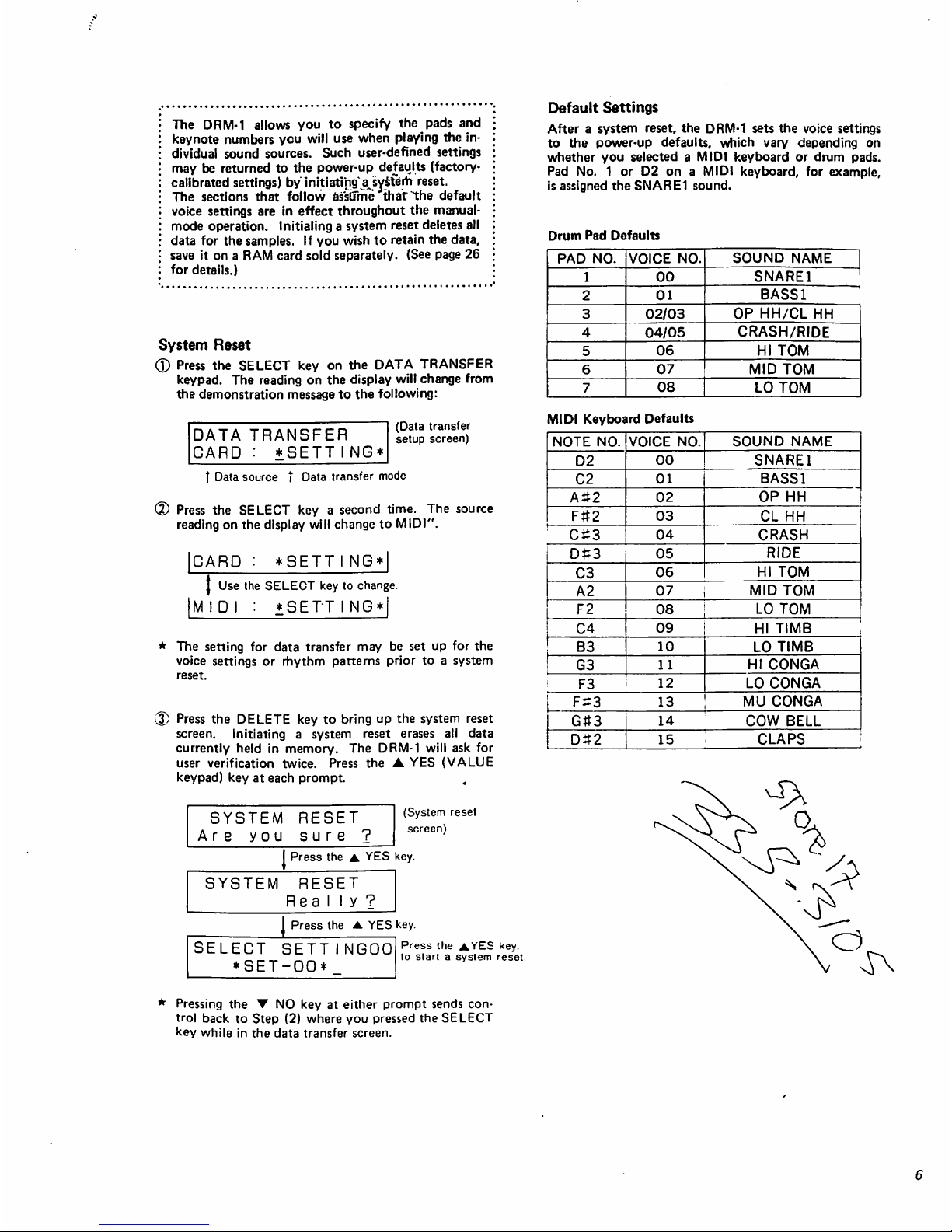
The
DRM-1
allows
you
to
specify
the
pads
and
keynote
numbers
you
will
use
when
playing
the
in
dividual
sound
sources.
Such
user-defined
settings
may
be
returned
to
the
power-up
defaults
(factory-
calibrated
settings)
by
initiating'ajiysferh
reset.
The
sections
that
follow
assume
that
the
default
voice
settings
are
in
effect
throughout
the
manual-
mode
operation.
Initialing
a
system
reset
deletes
all
data
for
the
samples.
If
you
wish
to
retain
the
data,
save
it
on a RAM
card
sold
separately.
(See
page
26
for
details.)
System
Reset
(D
Press
the
SELECT
key
on
the
DATA
TRANSFER
keypad.
The
reading
on
the
display
will
change
from
the
demonstration
message
to
the
following:
DATA
TRANSFER
CARD : *SETTING*
(Data
transfer
setup
screen)
T
Data
source t Data
transfer
mode
<D
Press
the
SELECT
key a second
time.
The
source
reading
on
the
display
will
change
to
MIDI".
ICARD
:
*SETTI
NG*|
J
Use
the
SELECT
key
to
change.
IMIDI
:
*SETTING*|
*
The
setting
for
data
transfer
may
be
set
up
for
the
voice
settings
or
rhythm
patterns
prior
to a system
reset.
(3)
Press
the
DELETE
key
to
bring
up
the
system
reset
screen.
Initiating
a
system
reset
erases
all
data
currently
held
in
memory.
The
DRM-1
will
ask
for
user
verification
twice.
Press
the ▲ YES
(VALUE
keypad)
key
at
each
prompt.
,
SYSTEM
RESET
Are
you
sure
?
(System
reset
screen)
I
Press
the ▲ YES
key.
SYSTEM
RESET
Rea
My?
Press
the ▲ YES
key.
SELECT
SETT
*SET-OO*
NGOO
Press
the
AYES
key.
to
start a system
reset.
Default
Settings
After a system
reset,
the
DRM-1
sets
the
voice
settings
to
the
power-up
defaults,
which
vary
depending
on
whether
you
selected a MIDI
keyboard
or
drum
pads.
Pad
No. 1 or
D2
on a MIDI
keyboard,
for
example,
is
assigned
the
SNARE1
sound.
Drum
Pad
Defaults
Pressing
the ▼ NO
key
at
either
prompt
sends
con
trol
back
to
Step
(2)
where
you
pressed
the
SELECT
key
while
in
the
data
transfer
screen.
Page 7

BEFORE
EDITING
PARAMETERS
The
DRM-1
operates
in
conjunction
with
the
remote
control unit
that
allows
access
to
all
programmable
functions.
Once
the
necessary
parameters
are
set,
the
remote
player
has
full.control
over
ttje^DRM-1
func
tions
except
for
the
power
switob
a.n^yolume
control.
On
the
front
panel
of
the
DRM-T
is
the
REMOTE
CON
TROL
switch
used
to
disable
remote
control
to
prevent
wireless
signal
interference
when
there
is
more
than
one
DRM-1
unit
positioned
side
by
side.
Always
check
that
the
switch
is
on
before
starting
operation.
Outline
of
Remote
Parameter
Control
A
number
of
DRM-1
functions
are
roughly
broken
down
into
the
following
three
categories,
which
represent
the
corresponding
remote
control
unit
keypads:
the
SET
TING
group
to
set
up
sound
data
for a drum
set,
the
PATTERN
group
to
record
and
play
back
rhythm
patterns
(sequencer),
and
other
group
of
keypads
used
to
control
the
SETTING,
PATTERN,
and
all
other
DRM-1
parameters.
The
third
group
consists
of
three
keypads:
the
SYSTEM
group
to
determine
the
way
the
DRM-1
controls
ex
ternally
connected
equipment,
the
MIDI
group
to
con
trol
input/output
operations,
and
the
DATA
TRANS
FER
group
to
allow
data
exchange
across
the
DRM-1
interface.
These
keypads
allow
instant
access
to
values,
parameters,
and
other
current
settings,
which
can
be
changed
with
the
CURSOR
control
and
VALUE
keys.
Message
Format
and
Basic
Edit
Commands
The
liquid
crystal
display
(LCD)
is
sixteen
columns
by
two
lines
wide.
Use
the
rear
panel
CONTRAST
knob
to
adjust
the
character
legibility.
1
Setting
number
SELECT
SETTINGOO
♦SET-00*
I
Setting
name t Cursor
When
the
POWER
switch
is
turned
on. the
DRM-1
dis
plays
information
in
this
format
after a sign-on
message.
(The
exact
setting
number
and
name
may
be
different,
depending
on
the
settings
in
effect
the
last
time
the
power
was
turned
off.)
Every
parameter
is
set
to
whatever
value
is
stored
in
memory.
The
parameters
are,
for
example,
set
for
demonstration
at
time
of
shipment.
The
process
of
changing
or
correcting
parameters
is
referred
to
as
"editing".
Usually,
the
upper
half
of
the
display
shows
the
para
meter
selected;
the
lower
half,
the
values
currently
assigned
to
that
parameter.
(Some
messages
display
the
value
assigned
to a parameter
in
the
upper
half
of
the
display.)
The
underscore
appearing
immediately
below a character
is
called a "cursor",
which
indicates
the data
field
which
may
be
changed.
The
CURSOR
control
keys
move
the
cursor
across
the
display.
Place
the
cursor
under
the
parameter
you
wish
to
edit,
then
press
the
VALUE
keys
to
enter a new
value.
The new
value
specified
in
this
manner
may
be
set
to
default
with
the
system
reset
command.
(See
page 6 for
details.)
EDITING
THE
PARAMETERS
1
<SETTING
GROUP)
Voice
is a parameter
segment
that
defines
sound
gener
ation,
for
which
the
DRM-1
allows
access
to
sixteen
such
segments.
(The
voicing
capacity
for
simultaneous
out
put
is
twelve
notes.)
Along
with
the
built-in
timbre
data,
each
voice
segment
is
fully
compatible
with
any
of
the
ROM
cards
for
the
DDD-1/5.
The
SETTING
group
specifies
the
instrument
type,
pitch,
volume,
MIDI
transmit/receive
channels,
and
other
settings
which
each
voice
segment
will
control.
The
DRM-1
alone
can
store
up
to
sixteen
such
settings,
each
consisting
of
sixteen
voice
segments
with
or
with
out a user-defined
name.
A
SETTING
15
(Setting
name)
23-timbre
built-in
sound
source
Figure
1
SETTING
The
SETTING
key
selects
the
setting
number
that
identifies
one
of
the
sixteen
settings.
It
also
allows
the
change
of a setting
name.
Subsequent
edit
commands
are
valid
only
for
data
specified
with
the
setting
num
ber.
(Tj
Selecting
a
Setting
Number
(D
Press
the
SETTING
key
to
bring
up
the
SELECT
SETTING
screen.
1
Setting
number
SELECT
SETTINGOO
*SET-00*_
(SELECT
SETTING
screen)
t
Setting
name
'%)
Press
the
SELECT
key
to
specify
the
setting
number.
SETT I NGOO | -Setting
number
t
SELECT
key
♦
(Speedy a selling
number
1 c between
00
anc
15
)
Page 8

(2)
Creating
a
Setting
Name
The
DRM-1
allows
creation
of a setting
name
consisting
of
up
to
eight
alphanumeric
characters
including
symbols.
If
not
necessary,
this
entire
step
becomes
optional.
• ■ .'."**'
®
Place
the
cursor
under
the^characterto
be
changed,
using
the
CURSOR
control
keys.
(D
Use
the
VALUE
keys
to
select
the
new
character.
+SET-00*
|
Use
the
CURSOR
control
and
VALUE
keys.
MY-DRUMS
I
<Characters
Valid
in a Setting
Name>
!"
=$*S"
()* + .-.
012345B7B9:
:< = >?a
ABCDEFGHIJKLMNOPQRSTUVWXYZ
¥.
A_\
abcdefghijk
Imnooarstuvvvxyz — sp
Space
'
*
The
SELECT
key,
intended
for
selecting
the
voice
number,
allows
access
to
setting
numbers
only
for
the
SELECT
SETTING
screen.
All
edit
commands
dis
cussed
hereafter
are
valid
only
for
parameters
selected
with
the
SELECT
key.
VOICE
The
VOICE
SETTING
screen
timbres
to
be
assigned
to
any
of the
voice
settings
numbered
from
00
to
15.
It
also
determines
the
settings
for
the
PHASE
effect.
When
the
VOICE
key
is
pressed,
the
upper
half
of
the
display
reads
VOICE
SETTING
##
(where
##
is
the
current
setting
number);
the
lower
half
shows
the
current
voice
number,
the
name
of
the
timbre
assigned
to
that
voice,
and
the
sound
mode.
Pressing
the
VOICE
key a second
time
switches
the
lower
half
of
the
dis
play
to
the
PHASE
setup
screen.
Qj
Selecting
a
Sound
Name
(D
Press
the
VOICE
key
to
bring
up
the
VOICE
SET
TING
screen.
VOICE
SETTING00
00=
SNARE
1:I00M
t
Voice
number t Sound
name j *-
(VOICE
SETTING
screen)
Sound
mode
L-Sound
number
(2)
Select
the
voice
number
of
the
data
to
be
changed,
using
the
SELECT
key.
00=
SNARE
1
00M
I
Press
the
SELECT
keys.
(Select a voice
number
from
00
to
15.)
1
5
(D
Select
the
sound
number
of a timbre
to be
assigned
to
thecurrent
voice,
using
the
VALUE
keys.
[00=
SNARE
1
:
10
DM
I
J
Use
the
VALUE
keys.
C48
£
Built-in
sound
source
00
to
22
ROM
card
sound
source
(Timbres
selected
from
up
to
four
cards)
(The
sound
source
alternates
each
time a key
is
pressed.)
Figure
2
<
Sound
Number
and
Sound
Mode
>
The
DRM-1
has
built-in
data
for
timbres
which
are
parameter
compatible
with
the
ROM
cards
for
the
DDD-1/5.
Each
timbre
is
assigned a unique
code
called
the
sound
number,
which
appears
on
the
display
when a voice
parameter
assignment
is
changed.
Built-in
sound
source
ROM
card
sound
source
Figure
3
Built-in
sound
source
selected
Twelfth
sound
from
the
built-in
sound
source
Memory
card
sound
source
selected
Memory
card
in
the
CARD
2
slot
selected
First
sound
from
the
memory
card
Note
1:
This
procedure
overrides
the
previous
setting
and
sets
the
PHASE
to
000.
Note
2:
When
using a ROM
card,
be
sure
to
set
it
in
place
before
pressing
the
VOICE
key,
which
instructs
the
DRM-1
to
check
the
slots
for
a
missing
card
before
loading
data.
(2)
Selecting
a
Sound
Mode
The
POLY,
MONO,
and
EXCLUSIVE
sound
modes
each
provide
independent
control
over
the
voice
settings
defining
the
way
the
DRM-1
will
generates
sounds
consisting
of
up
to
twelve
notes
at a
time.
1)
Press
the
VOICE
key
to
select
VOICE
SETTING
screen.
(2)
Move
the
cursor
to
the
sound
mode
field,
using
the
CURSOR
control
keys.
VOICE
SETTING00
00=
SNARE
1:I00M
(VOICE
SETTING
screen)
T
Current
sound
mode
Page 9

(D
The
display
cycles
through
the
POLY.
MONO,
and
EXCLUSIVE
modes
each
time
the
VALUE
key
is
pressed.
Select
the
sound
mode
to
match
the
appli
cation.
100=
SNARE
1
:
I
Q,Q.Ej'?aoLY
mode)
J
Press
the
VALUE
key.
M
(MONO
mode)
♦
Press
the
VALUE
key.
E
(EXCLUSIVE
mode)
POLY
mode:
When
continually
repeating
the
same
voice,
the
POLY
mode
ensures
that
new
tones
do
not
disrupt
the pre
vious
ones
part
way
through,
causing
one
voice
to
over
lap
with
the
next.
To
produce
long,
repeated
decres-
cendos
like
the
cymbals,
the
POLY
mode
allows
trailing
notes
to
overlap
so
that there
is
no
disruption
resulting
in
unnatural
output.
Key
(or
pad)
hit
Overlap
Figure
4
MONO
Mode:
As
opposed
to the
POLY
mode,
the
MONO
mode
cuts
trailing
notes
off
before
the
new
notes
when
repeating
the
same
voice.
Tom
sounds,
for
example,
may
sound
unnatural
unless
they
are
set
to
the
MONO
mode.
Key
(or
pad)
hit
No
overlap
Figure
5
EXCLUSIVE
Mode:
Repeatedly
playing
more
than
one
voice
in
the
EX
CLUSIVE
mode
cuts
the
trailing
notes
off
when
the
new
ones
start.
Use
the
EXCLUSIVE
mode
when
closed
hi-hat
follows
open
hi-hat,
mute
conga
follqws
open
conga,
and
other
sequences
that
will
sound
un
natural
when
overlapped.
Open
hi-hat
Closed
hi-hat
Open
Open
(3)
Selecting
the
PHASE
Parameter
The
DRM-1
is
capable
of
assigning
the
same
timbre
to
multiple
voices.
This
function
allows a single
drum
pad
or a key
(MIDI
message)
to
simultaneously
use
two
or
more
timbres.
The
DRM-1
also
..allows
the
start-up
phase
shift
to
be
varied
in
128
steps
per
voice.
Mixing
timbres
with
dif
ferent
phase
shifts
adds
the
effects
of a phaser
or f I
anger
to
the
output.
This
technique
is
extremely
useful
when
defining
the
sounds
of
the
cymbal,
snare
drum,
and
similar
instruments.
®
Press
the
VOICE
key a second
time
to
display
the
PHASE
setup
screen.
VOICE
SETTINGOO
00=
SNARE
I:I00M
VOICE
SETTINGOO
00:PHASE=000
(VOICE
SETTING
screen)
Press
the
VOICE
key
to
switch
the
cursor
between
the
screen.
(PHASE
setup
screen)
Select
the
PHASE
value,
using
the
VALUE
key.
5:PHASE=000
Use
the
VALUE
keys
to
seiec:
a
value
between
OOO
and
127.
27
CRASH
is
one
effect
that
makes
the
phaser
sound
highly
noticeable.
Make
sure
that
the
pan,
sound
mode,
tune,
and
decay
settings
are
identical
among
the
voices.
As a special
technique
using
the
PHASE
parameter,
setting
the
tune
of
either
voice
one
to
three
levels
higher
generates
the
effect
of a flanger.
MIDI
The
voice
settings
are
an
essential
part
that
defines
the
quality
of
sounds
the
DRM-1
generates.
Setting
up
the
voice
parameters
for
the
desired
sounds
requires
assign
ing
drum
pad
or
keyboard
signals
to
the
keynote
num
bers.
To
this
end,
the
MIDI
SETTING
screen
allows
difinition
of
the
keynote
number
range
and
MIDI
transmit/receive
channels
per
voice.
IT]
Setting
the
Keynote
Number
(1)
Press
the
MIDI
key
to
select
the
MIDI
SETTING
screen.
MIDI
SETT
INGOO
00:Qi1-C 2 CH=01
(MIDI
SETTING
screen)
t
t-Top
"Ote
l-Origial
note
Voice
number
MIDI
Channel
Figure
6
2
Set
up
the
voice
parameters
for
the
keynote
number
to
be
changed,
using
the
SELECT
key.
Page 10
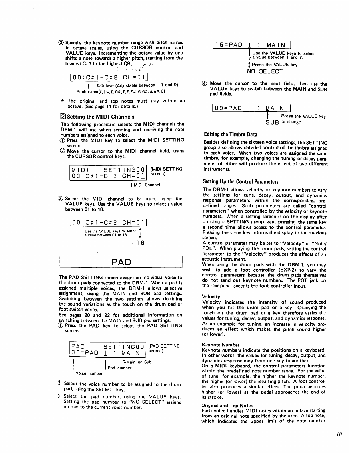
Specify
the
keynote
number
range
with
pitch
names
in
octave
scales,
using
the
CURSOR
control
and
VALUE
keys.
Incrementing
the
octave
value
by
one
shifts a note
towards a higher
pitch,
starting
from
the
lowerst
C-1
to
the
highest
C9.. . ,.,
,-
5 = PAD
MA I N
OO
-C?2
CH
=
|
t.
Octave
(Adjustable
between
-1
and
9}
Pitch
name(C,C#.D.DS.E,F,F2,G.GJ:.A.Ai:,B)
*
The
original
and
top
notes
must
stay
within
an
octave.
(See
page
11
for
details.)
(2)Setting
the
MIDI
Channels
The
following
procedure
selects
the
MIDI
channels
the
DRM-1
will
use
when
sending
and
receiving
the
note
numbers
assigned
to
each
voice.
(D
Press
the
MIDI
key
to
select
the
MIDI
SETTING
screen.
©
Move
the
cursor
to
the
MIDI
channel
field,
using
the
CURSOR
control
keys.
M I D
SETTINGOO
00:Gt1-C 2 CH=01
(MIDI
SETTING
screen)
T
MIDI
Channel
(3)
Select
the
MIDI
channel
to
be
used, using
the
VALUE
keys.
Use
the
VALUE
keys
to
select a value
between
01
to
16.
OO:C
CH = 0I
Use
the
VALUE
keys
to
select
a
value
between
01
to
16
PAD
The
PAD
SETTING
screen
assigns
an
individual
voice
to
the
drum
pads
connected
to the
DRM-1.
When a pad
is
assigned
multiple
voices,
the
DRM-1
allows
selective
assignment,
using
the
MAIN
and
SUB
pad
settings.
Switching
between
the
two
settings
allows
doubling
the
sound
variations
as
the
touch
on
the
drum
pad
or
foot
switch
varies.
See
pages
20
and
22
for
additional
information
on
switching
between
the
MAIN
and
SUB
pad
settings.
(D
Press
the
PAD
key
to
select
the
PAD
SETTING
screen.
PAD
00=PAD
SETT
INGOO
I : MA
IN
(PAD
SETTING
screen)
t
-Main
or
Sub
Pad
number
Voice
number
2
Select
the
voice
number
to
be
assigned
to
the
drum
pad,
using the
SELECT
key.
3
Select
the
pad
number,
using
the
VALUE
keys.
Setting
the
pad
number
to
"NO
SELECT"
assigns
no
pad
to
the
current
voice
number.
|
Use
the
VALUE
keys
to
select
-t a value
between 1 and
7.
J
Press
the
VALUE
key.
NO
SELECT
©
Move
the
cursor
to
the
next
field,
then
use
the
VALUE
keys
to
switch
between
the
MAIN
and
SUB
pad
fields.
00=PAD
1
MA I N
}
Press
the
VALUE
key
S U B
t0
change.
Editing
the
Timbre
Data
Besides
defining
the
sixteen
voice
settings,
the
SETTING
group
also
allows
detailed
control
of
the
timbre
assigned
to
each
voice.
When
two
voices
are
assigned
the
same
timbre,
for
example,
changing
the
tuning
or
decay
para
meter
of
either
will
produce
the
effect
of
two
different
instruments.
Setting
Up
the
Control
Parameters
The
DRM-1
allows
velocity
or
keynote
numbers
to
vary
the
settings
for
tune,
decay,
output,
and
dynamics
response
parameters
within
the
corresponding
pre
defined
ranges.
Such
parameters
are
called
"control
parameters"
when
controlled
by
the
velocity
or
keynote
numbers.
When
a setting
screen
is
on
the
display
after
pressing a SETTING
group
key,
pressing
the
same
key
a
second
time
allows
access
to
the
control
parameter.
Pressing
the
same
key
returns
the
display
to
the
previous
screen.
A
control
parameter
may
be
set
to
"Velocity"
or
"Note/
PDL".
When
playing
the
drum
pads,
setting
the
control
parameter
to
the
"Velocity"
produces
the
effects
of an
acoustic
instrument.
When
using
the
drum
pads
with
the
DRM-1,
you
may
wish
to
add a foot
controller
(EXP-2)
to
vary
the
control
parameters
because
the
drum
pads
themselves
do
not
send
out
keynote
numbers.
The
POT
jack
on
the
rear
panel
accepts
the foot
controller
input.
Velocity
Velocity
indicates
the
intensity
of
sound
produced
when
you
hit
the
drum
pad
or a key.
Changing
the
touch
on
the
drum
pad
or a key
therefore
varies
the
values
for
tuning,
decay,
output,
and
dynamics
response.
As
an
example
for
tuning,
an
increase
in
velocity
pro
duces
an
effect
which
makes
the
pitch
sound
higher
(or
lower).
Keynote
Number
Keynote
numbers
indicate
the
positions
on a keyboard.
In
other
words,
the
values
for
tuning,
decay,
output,
and
dynamics
response
vary
from
one
key
to
another.
On a MIDI
keybaord,
the
control
parameters
function
within
the
predefined
note
number
range.
For
the
value
of
tune,
for
example,
the
higher
the
keynote
number,
the
higher
(or
lower)
the
resulting
pitch. A foot control
ler
also
produces a similar
effect:
The
pitch
becomes
higher
(or
lower)
as
the
pedal
approaches
the
end
of
its
stroke.
Original
and
Top
Notes
Each
voice
handles
MIDI
notes
within
an octave
starting
from
an
original
note
specified
by
the
user. A top
note,
which
indicates
the
upper
limit
of
the
note
number
10
Page 11

range,
must
stay
within
the
octave
(twelve-step
chro
matic
scale)
starting
from
the
original
note.
The
voice
does
not
respond
to
any
notes
outside
the
prescribed
note
number
range.
The
control
parameters,
tuning,
decay,
output,
and
dynamic
response
values,
charge
according
to
pitch
or
keynote.:n*urnber
played
within
the
selected
range.
..■■:--:-•>-
_-
*
If
the
original
and
stop
notes
are
at
an
identical pitch,
the
DRM-1
cannot
produce
any
note
number
but
the
one
defined
by
that
pitch.
Setting
up
the
control
parameters
for
this
single
MIDI
note
number
there
fore
will
not
produce
any
noticeable
effect.
TUNE
The
TUNE
key
is
used
to
control
the
tuning
{pitch)
of
the
timbre
assigned
to
each
voice.
The
timbre
fortoms
ranges
between
000
and
127
with a middle
level
at
064.
It is
variable
in
increments
of
063
and
in
decrements
of 064,
starting
from
the
middle
level
(approximately
9.45-cent
changed
per
step).
Cymbal
sounds
starts
from
an
original
tuning
at
000,
which
is
the
lowermost
pitch.
The
upper
limit
of
the
variable
range
is
127.
The
control
parameters
can
vary
the
original
tunes
in
up
to
twelve
steps,
using
velocity
or
keynote
numbers.
(D
Setting
the
TUNE
Parameter
(D
Press
the
TUNE
key
to
select
the
TUNE
SETTING
screen.
TUNE
SETTINGOO
00=
SNARE
1:T064
(TUNE
SETTING
screen)
T
Tune
'-Voice
name
Voice
number
(D
Select
the
voice
number,
using
the
SELECT
key.
(D
Specify
the
value
for
the
TUNE
parameter,
using
the
VALUE
keys.
I
0
0
=
SNARE
1
:TOOOl
Press
the
VALUE
key
to
select
♦
a
value
between
000
and
127.
\
1
27
(2)
Setting
the
TUNE
Control
Paramter
(D
Press
the
TUNE
key a second
time
to
access
the
control
parameter.
TUNE
SETTINGOO
00=
SNARE
1:T064
|
Press
the
TUNE
key
to
change
TUNE
SETTINGOO
00:+VeIoc i t y 000
(Control
parameter
setup
screen)
*
t
-Controller
-Control
sign
Voice
number
f
Sensitivity
(2)
Move
the
cursor
to
the
control
sign
field,
then
specify
whether
the
control
parameter
will
increase
or
decrease
the
tuning, using
the
VALUE
key.
If
the
plus
sign
is
selected,
the
pitch
will
increase
beyond
that
defined
by
the
TUNE
parameter
as
the
key
note
number
or
velocity
value
increases.
Selecting
the
minus
sign
will
cause
the
pitch
to
decrease.
|
00:±VeIoc
i
ty
0
D0|
♦
Use
the
VALUE
keys
to
switch
^between
" + "
and " —"
+ : TUNE
UP
-
:TUNE
DOWN
*
If
the
TUNE
parameter
is
set
to
127,
selecting
the
plus
sign
will
not
allow
the
control
parameter
to
increase
preset
tuning
any
further.
Likewise,
selecting
minus
sign
when
tuning
is
000
does
not
allow
any
lower
value.
(D
Move
the
cursor
to
the
controller
field,
then
set
it
to
velocity
or
keynote
number,
using
the
VALUE
keys.
Use
the
VALUE
keys
to
switch
between
"Velo
city"
and
"Note/PDL".
00 : +Ve I oc i t
y.
000
Use
the
VALUE
keys
to
switch
J
between
"Velocity"
and
"Note/PDL".
Note/PDL
4T
Move
the
cursor
to
the
sensitivity
field,
then
specify
the
control
parameter
sensitivity
within
the
000
to
127
range,
using
the
VALUE
keys
(disabled
when
set
to
000).
|00
:
+VeIoc
i
ty
OOP!
Use
the
VALUE
keys
to
select
a
value
between
000
and
127.
27
For
the
optimum
effect,
set
the
TUNE
parameter
to
000.
Set
it
to
127
if
the
control
sign
is
set
to
"-".
DECAY
The
DECAY
parameter
determines
the
sound
attenuat-
tion
RATE
(or
length)
of
each
voice.
The
control
parameter
uses
velocity
or
keynote
number
to
vary
DECAY
intensity
(in
up
to
fifteen
steps).
3]
Setting
the
DECAY
Parameter
(I-
Press
the
DECAY
key
to
select
the
DECAY
SETT
ING
screen.
DECAY
SETTINGOO
00=
SNARE
I:D
15
(DECAY
SETTING
screen)
T
Decay
■Voice
name
Voice
iumber
Page 12

Select
the
voice
number,
using
the
SELECT
key.
Set the
DECAY
value,
using
the
VALUE
keys.
00=
SNARE
1
:D 00|
Use
the
VALUE
keys
to
select ♦ .:
a
value
between
00
and
"]£■-—"~.\*~-
1
5
(2)
Setting
the
Decay
Control
Parameter
(D
Press
the
DECAY
key a second
time
to access
the
control
parameter.
(D
Move
the
cursor to
the
control
sign
field,
then
specify
whether
the
control
parameter
will
increase
or
de
crease
decay,
using
the
VALUE
key.
If
you
select
the
plus
sign,
decay
will
enhance
the
effect
beyond
that
defined
by
the
DECAY
parameter
as
the
key
note
number
or
velocity
value
increases.
Selecting
the
minus
sign
sets
the
value
control
the
other
way
round.
•
If
the
DECAY
parameter
is
set
to
15,
selecting
the
plus
sign
will
not
allow
the
control
parameter
to
increase
preset
decay
any
further.
Similarly,
selecting
the
minus
sign
when
decay
is
00
does
not
allow
any
lower
value.
(3)
Move
the
cursor
to
the
controller
field,
then
set
it
to
velocity
or
keynote
number,
using
the
VALUE
keys.
Use
the
VALUE
keys
to
switch
between
"Velo
city"
and
"Note/PDL".
■4
Move
the
cursor to
the
sensitivity
field,
then
specify
the
control
parameter
sensitivity
within
the
000
to
015
range,
using
the
VALUE
keys
(disabled
when
set
to
000).
*
For
the
optimum
effect,
make
sure
that
the
DECAY
parameter
is
set
to
000.
Set
it
to
015
if
the
control
sign
is
set
to
"-".
LEVEL
The
LEVEL
parameter
controls
the
output
volume
per
voice.
0
Press
the
LEVEL
key
to
select
the
LEVEL
SETTING
screen.
LEVEL
SETTINGOO
00=
SNARE
1:L
15
(LEVEL
SETTING
screen)
Lvnif
T
Level
-Voice
name
Voice
number
(D
Select
the
voice
number,
using
the
SELECT
key.
(3)
Set the
LEVEL
value,
using
the
VALVE
keys.
|
0
0
=
SNARE
1
:L
1
5|
Use
the
VALUE
keys
to
select
|
a
value
between
00
and
15.
?
00
OUTPUT
The
OUTPUT
parameters
assign
the
independent
voice
output
to
separate
output
jacks,
which
come
in
two
types
—the
OUTPUT
jacks
for
stereophonic
output
and
the
MULTI
OUT
jacks.
The
pan-pot
parameters
allow
putting
the
individual
voice
output
in
up
to
seven
posi
tions
across the
stereo
range,
which
extends
from C at
the
center
towards
the
leftmost
L3
and
the
rightmost
R3.
The
MULTI
OUT
jacks
(M1
through
M8)
handle
output
which
you
do
not
want
to
channel
through
the
stereo
jacks.
Such
output
may
be
fed
into
an
external
effector
or
equalizer
to
handle
reverb
and
other
effects.
The
pan-pot
parameters
allow
stereo
range
control
in
much
the
same
way
as
othersound
parameters
are
edited.
It
is
therefore
possible
to
pan output
with
velocity
and
keynote
numbers.
After
output
setup,
pressing
the
OUTPUT
key a second
time
switches
the
lower
half
of
the
display
to a control
parameter
screen.
CD
Setting
the
OUTPUT
Parameter
<£•
Press
the
OUTPUT
key
to
select
the
OUTPUT
SET
TING
screen.
OUTPUT
SETTINGOO
00=
SNARE
1:0
LI
(OUTPUT
SETTING
screen)
t
Output
assign
"-Sound
name
Voice
number
1
Select
the
voice
number
with
the
SELECT
key.
X
Specify
the
pan-pot
and
MULTI
OUT
parameters,
using
the
VALUE
keys.
00=
SNARE
O
LI
|
Use
the
VALUE
keys
L3-R3.MI-M8
to
change.
Stereo
range
LEFT
■
L3
L2
—t—
LI
H
RIGHT
C
Rl
(CENTER)
R2
R3
MULTI
OUT
jack
Ml
M2
M3
M4
M5
M6
M7
M8
*
Setting
the
output
for
MULTI
OUT
automatically
switches
the
sound
mode
to
MONO.
Note,
however,
that
the
display
reading
retains
the
setting
for the
PLOY
mode,
which
is
cleared
once
MULTI
OUT
is
selected.
For a well-balanced
output,
assign
cymbal
and
other
POLY-mode
sounds
to
stereophonic
out
put
and
bass
drum,
torn,
and
other
non-polyphonic
sounds
to
MULTI
OUT.
12
Page 13

(2]
Setting
the
Pan-pot
Control
Parameter
(D
Press
the
OUTPUT
key a second
time
to
access
the
control
parameters.
OUTPUT
SETTJNGQO.,
0 0 :
+Ve
loci t y ' D"DQ
(dbritrol
parameter
setup
screen)
t
Sensitivity
■Controller
-Control
sign
Voice
number
(D
Move
the
cursor
to
the
control
sign
field,
then
specify
whether
the
control
parameter
will
pan
the
output
towards
the
left
or
right,
using
the
VALUE
key.
If
the
plus
sign
is
selected,
the
output
will
shift
from
L3
to
R3
as
the
key
note
number
or
velocity
value
in
creases.
Selecting
the
minus
sign
sets
the
pan
control
the
other
play
round.
*
If
the
pan-pot
parameter
is
set
to
L3,
setting
the
con
trol
sign
to
minus
will
not
shift
output
towards
the
left
any
further.
If
the
parameter
is
set
to
R3,
the
control
sign
set
to
plus
is
incapable
of
shifting
output
towards
the
right
any
further.
(D
Move
the
cursor
to
the
controller
filed,
then
set
it
to
velocity
or
keynote
number,
using
the
VALUE
keys.
Use
the
VALUE
keys
to
switch
between
"Velocity"
and
"Note/PDL".
(J)
Move
the cursor
to
the
sensitivity
field,
then
specify
the
control
parameter
sensitivity
within
the
000
to
006
range,
using
the
VALUE
keys.
[2]
Setting
the
RESPONSE
Control
Parameter
0
Press
the
RESPONSE
key a second
time
to
access
the
control
parameter.
(D
Move
the
cursor
to
the
control
sign
field,
then
specify
whether
the
control
parameter
will
increase
or
de
crease
the
dynamics
response,
using
the
VALUE
keys.
Selecting
the
plus
sign
increases
the
dynamics
response
output
beyond
that
defined
by
the
LEVEL
parameter
as
the
key
not
number
or
velocity
value
increases.
Selecting
the
minus
sign
decreases the
dynamic
response
as
velocity
increases.
*
When
the
control
sign
field
is
set
to
"•",
increasing
velocity
reduces
the
output
level.
If
the
dynamics
response
is
set
to
127,
using
the
"+"
control
sign
causes
the
output
to
start
from
the
highest
level
before
the
control
parameter
can
cause
changes.
(3)
Move
the
cursor to
the
controller
field,
then
set
it
to
velocity
or
keynote
number,
using
the
VALUE
keys.
Coarse
level
changes
will
result
by
selecting
"Note/
PD
L",
which
uses
only
12
steps
as
opposed
to
"Velo
city",
using
128
steps.
(4)
Move
the
cursor
to
the
sensitivity
field,
then
specify
the
control
parameter
sensitivity
within
the
000
to
015
range,
using
the
VALUE
keys.
If
the
sensitivity
setting
is
000,
the
control
parameter
will
completely
suppress
velocity-dependent
changes.
If
the
dynamic
response
is
set
to
000,
no
sound
will
be
generated.
Otherwise,
increasing
the
sensitivity
expands
the
range
of
velocity-controlled
changes.
COPY
RESPONSE
In
addition
to
velocity
data
from
drum
pads
or
key
board,
the
DRM-1
recognizes
foot
controller
action
and
MIDI
keynote
numbers
to
change
the
output
volume.
Unlike
the
OUTPUT
level
parameters
which
make
the
individual
voice
output
well-balanced,
the
RESPONSE
parameter
sets
up
the
dynamic
response
which
varies
the
output
in
accordance
with
foot
controller
action
and
MIDI
keynote
numbers.
OD
Setting
the
RESPONSE
Parameter
The
RESPONSE
parameter
specifies
the
level
on
which
changes
will
be
based.
(D
Press
the
RESPONSE
key
to
select
the
RESP
SET
TING
screen.
D.
RESP
SETT I NGOO
00=
SNARE
1:R000
(RESP
SETTING
screenj
T
Dynamics
Response
name
Voice
number
(2)
Select
the
voice
number,
using
the
SELECT
key.
(§)
Specify a value
for
the
dynamic
response,
using
the
VALUE
keys.
00=
SNARE
1:R000
Use
the
VALUE
keys
to
select
a
value
between
000
and
127
27
The
COPY
function
allows a complete
backup
copy
to
be
made
of
the
sound
parameters
in a setting.
It
does
this
by
copying
the
entire
setting
to
an
area
allocated
to
an
unused
setting
number.
This
function
is
useful
in
situations
where
the
original
setting
is
to
be
saved,
but
another
version
is
to
be
made
based
on
this
original
setting.
Edited
parameters
may
also
be
returned
to the
default
values
(standard
settings
used
by
KORG).
Q]
Copying
a
Parameter
Setting
0
Press
the
COPY
key
to
select
the
COPY
SETTING
screen.
Setting
number
of
source
setting.
■
COPY
TO
SETT
INGOO
00
Sur
e?
(COPY
SETTING
screen)
*
Setting
number
of
the
destination
(|)
Select
the
setting
number
of
the
destination.
Do
not
select
the
setting
number
for
data
which
is
to
be
retained.
New
data
will
overwrite
any
data
at
the
destination.
TO
00
Sure?
1
5
Use
the
SELECT
key
to
specify
a
value
between
00
and
15.
13
Page 14

(D
Press
the
AYES
key
(VALUE
keypad)
to
start
copy
ing.
Pressing
the T NO
key
(VALUE
keypad)
instead
cancels
copying
and
sends
control
back
to
Step
(2)
where
the
SELECT
key
was
pressed.
TO
00
.
Su,-i-€gM
I
Press
the A YES
key
*
,
(VALUE
keypad)
TO
00
Execute
I
TOO
0
Fi n i s n
Press
the ▲ YES
key
(VALUE
keypad)
to
restore
the
default
values.
Pressing
the T NO
key
(VALUE
key
pad)
instead
cancels
the
command.
Pressing
the
▲YES
key
will
replace
the
selected
setting
with
the
default
values.
De
fau
I
t
Su
r
e2l
I
Press
the
AYES
key
Def
au
I
t
Executel{VALUE
I
Default
F
i
n
i
sh|
Restoring
the
Default
Parameter
Setting
Press
the
COPY
key a second
time
to
select
the
"De
fault"
prompt.
When
copying
is
complete,
the
display
remains
inac
tive
with
the
"Finish"
message,
which
indicates
that
the
next
operation
may
follow.
COPY
SETTING00
De f auIt
Sure?
(Restore-default
screen)
EDITING
THE
PARAMETERS
2
{PATTERN
GROUP)
Outline
of
Operation
In
addition
to
the
capabilities
for a drum
sound
source
module,
the
DRM-1
incorporates
the
functions
of
a
digital
sequencer.
While
the
SETTING
group
provides
editing
facilities
for
sound
parameters,
the
PATTERN
group
allows
access
to
all
sequencer
functions.
The
built-in
sequencer
accepts
data
from
drum
pads
or
a
MIDI
keybaord.
It
employs a real-time
input
system
which
allows
saving
rhythm
pattern
data
with the
ease
of
a
tape
recorder.
Any
changes
may
be
made
to
pattern
data
in
memory
by
means
of
punch-in,
punch-out,
or
overdubbing.
The
DRM-1
stores
pattern
data
for
up
to
sixteen
songs,
together
with
user-defined
titles.
RAM
cards
are
availa
ble
as
external
storage
options.
Location
Display
The
location
field
of
the
display
shows
the
progress
of
a
tune
being
recorded
or
played
back.
The
reading
ap
pears
in a four-digit
value
starting
from
0000,
which
corresponds
to
the beginning
of a tune.
Unlike
the
tape
counter
on a tape
recorder,
the
readout
pace
varies
with
the
tempo
of a tune
because
it
always
advances
in
increments
of a quarter
note.
In a quarter-measure
tune,
for
example,
the
reading
advances
in
increments of
four
(0004)
per
measure,
which
is
equivalent
in
value
to
four
quarter
notes.
Changing
the
Location
When
rhythm
pattern
data
is
inactive,
the
SELECT
PATTERN
screen allows
changing
from
one
location
to
the
other
as
long
as
the
readout
remains
on
the
display.
The
following
section
explains
how
to
change
the
location
with
the
PATTERN
key.
SELECT
PATTERNOO
♦PTN-OO*
OOOO
Pattern
number
(SELECT
PATTERN
screen)
Pattern
nameT
I
T
Location
OOOO
X3
X2
XI
XO
Close
up
of
Location
Field
When
the
cursor
is
in
the
location
field,
the A and
T
keys
on
the
VALUE
keypad
move
the
current
location
back
and
forth,
respectively.
The
rate
of
increment
or
decrement
in
reading
varies
with
the
cursor
position
(X0,
X1.X2,
orX3).
1.
Cursor
in
the
X0
position
Holding
down
the ▲ key
continues
changing
the
loca
tion
in
increments
of
one;
holding
down
theT
key,
in
decrements
of
one.
The
DRM-1
plays
back
the
tune
as
the
value
is
changed.
Decrementing
the
value
plays
the
data
backwards,
but
timbres
do
not
reverse.
A
location
lower
than
0000
is
used
for
recording
an
introduction.
2.
Cursor
in
the
X1
position
The
value
changes
in
the
manner
just
described,
ex
cept
that
reverse
playback
is
not
available.
3.
Cursor
in
the
X2
position
Holding
down
the ▲ key
continues
changing
the
loca
tion
in
increments
of
four;
holding
down
the Y key,
in
decrements
of
four.
For a quarter-measure
tune,
the
reading
changes
per
bar
line.
Playback
is
not
available.
14
Page 15

4.
Cursor
in
the
X3
position
Holding
down
the A key
continues
changing
the
location
in
increments
of
three;
holding
down
the
T
key,
in
decrements
of
three.
For a three-quarter
measure,
the
reading
changes
per
bar
Hne.
Playback
is
not
available. " .'-"*'
*
The
location
cannot
be
"set
tieydrrff
0000
if
there
is
no
rhythm
pattern
data
in
memory.
Setting
Up
the
Tempo
The
PATTERN
group
allows
four
different
approaches
for
determining
the
tempo:
1.
Using
the
TEMPO
key
to
change
or
set
the
numerical
value
defining
the
initial
tempo
(See
page
17.)
2.
Varying
the
REC
TEMPO
value.
3.
Controlling
the
pedal
stroke
of a foot
controller
(EXP-2,
etc.)
connected
to
the
POT
PEDAL
jack
(See
page
21.)
4.
Controlling
the
foot
switch
connected
to
the
TAP
TEMPO
jack
for
use
as a
tap
tempo
switch
(See
page
16.)
(2)
Select
the
pattern
number,
using
the
SELECT
key.
START
The
START
key
is
used
to
start
playback
of a preset
rhythm
pattern.
Press
this
key
before
entering
or
editing a
rhythm
pattern
because
the
DRM-1
is
designed
for a real-time
write
operation.
The
START
key
always
starts
playback
from
trie
location
displayed.
STOP
The
function
of
the
STOP
key
is
two-fold:
inserting
a
pause
during
the
recording
or
playback
process
of
the
built-in
sequencer
or
initializing
the
location
count
to
0000.
Pressing
the
STOP
key
during
sequencer
operation
causes a pause
in
the
current
location.
Because
this
does
not
cause a reset,
pressing
the
START
key
starts
the
sequencer
operation
from
the
point
where
it
was
interrupted.
(Continue,
Start)
Pressing
the
STOP
key
when
the
sequencer
is
idling
resets
the
location
to
0000.
PATTERN
The
PATTERN
key
is
used
to
specify
the
pattern
num
ber,
create a pattern
name,
turn
repeat
control
on
and
off,
and
initiate
a
regular
playback
process.
Pressing
the
START
key
while
in
the
SELECT
PAT
TERN
screen
starts
playback
from
the
location
dis
played.
(Tj
Selecting
a
Pattern
Number
(D
Press
the
PATTERN
key
to
select
the
SELECT
PATTERN
screen.
If
the
repeat
control
is
on,
the
dis
play
will
show a repeat ( !||
).
(SELECT
PATTERN
screen)
SELECT
PATTERNOO
♦
SET-00*
0000
Pattern
number
-Location
Pattern
name
In
this
position
appears
a
repeat
(currently
off).
PATTERNO0
«-pattern
number
1
5
Press
the
SELECT
key
to
specify
a
value
between
00
and
15.
(2)
Creating
a Pattern
Name
The
selected
rhythm
pattern
may
be
assigned a name
consisting
of
up
to
eight
alphanumeric
characters
in
cluding
symbols.
If
not
necessary,
this
entire
step
be
comes
optional.
©
Place
the
cursor
under
the character
to be
changed.
(|)
Select
the
new
character,
using
the
VALUE
keys.
I
*PTN-00*
0000
I
I
Use
the
CURSOR
control
and
I
VALUE
keys
to
change.
|
MY-S0NG5
0000
|
*
See
page 7 for
the
list
of
characters
valid
in a setting
name.
(2
Turning
On
and
Off
the
Repeat
Control
Turning
on
the
repeat
control
sets
up
an
endless
loop,
in
which
the
same
passage
is
continuously
repeated
from
location
0000
until
the
STOP
key
is
pressed,
(j)
Set
the
cursor
between
the pattern
name
and
location
fields.
PTN-NAME_0000
T
Repeat
(currently
off)
<D
Turn
the
repeat
on
an
off,
using
the
VALUE
keys.
I
PTN-NAME_0000|
Repeat
(currently
on)
(Turn
the
repeat
on
and
off.
using
the
VALUE
keys.
PTN-NAMEI10000 I Repeat
(currently
on)
REC
The
REC
key
allows
access
to
parameters
for
recording
rhythm
patterns.
When
pressed,
the
REC
key
brings
up
a
screen
for
specifying
the
tempo,
introduction
count,
and
other
parameters
used
during
recording.
Pressing
the
START
key
terminates
the
parameter
setting
screen
and
starts
recording,
during
which
the
DRM-1
continues
recording
rhythm
patterns
exactly
as
they
are
played
on
drum
pads
or a MIDI
keyboard.
The
DRM-1
also
allows
use
of a foot
switch
for
sound
generation.
See
the
sections
for
the
SYSTEM
proup
(page
20)
and
MIDI
group
(page
24)
before
starting.
(T)
Recording
Rhythm
Patterns
0
Press
the
REC
key
to
select
the
RECORD
PATTERN
screen.
I
Pattern
*
number
RECORD
PATTERNOO
T=lP0
100%
0000
(RECORD
PATTERN
screen)
Tempo
t-Repeat
mark
lAvailable
memory
15
Page 16

The
tempo
field
indicates
the
playback
tempo,
which
is
adjustable
within
the
040
to
250
range.
The
avail
able
memory
indicates
the
amount
of
free
space
left
in
memory. A readout
of
100%
indicates
very
samll
memory
consumption.
If
the
repeat
control
is
ena
bled,
the
display
will
also
show a repe*af(
ill
)•
Pressing
the
REC
key
automatically
sets
the
location
to
0000
independent
of
the
amount
of
data
in
memory.
Because
a location
reset
sets
the
value
to
0000,
make
sure that
you
do
not
inadvertently
over
write
important
data.
Move
the
cursor to
the
tempo
field,
then
specify
the
value
to
be
used
during
recording.
If
the
tempo
has
already
been
set
(with
the
TEMPO
key,
tap-tempo
switch,
etc.).
this
step
becomes
optional.
|T
=
040
10056
OOOOl
Use
the
VALUE
keys
to
specity
a
value
between
040
and
250.
250
If
the
location
is
set
below
0000
(-16
at
the
lower
limit),
recording
will
start
after
an
introduction.
Setting the
location
to
-4,
for
example,
starts
record
ing
after a count
of
four
beats.
(If
not
necessary,
this
step
becomes
optional.)
|T=040
100%
OOOOl
Use
the
VALUE
keys
to
specify
a
value
between
-16
and
0000.
t
-1
B
(3)
Press
the
START
key
to
start
recording.
If
the
loca
tion
is
set
to
below
0000,
recording
will
follow
an
introduction.
If a foot
switch
(tap
tempo
switch)
is
used,
depressing
it
as
many
times
as
the
number
of
beats
in
the
specified
introduction
count
auto
matically
sets
the
tempo
and
starts
recording.
(D Once
recording
starts,
the
DRM-1
records
rhythm
patterns
exactly
as
they
are
played
on
the
MIDI
keyboard
or
drum
pads.
To
terminate
recording,
press
the
STOP
key.
Pressing
the
STOP
key
also
interrupts
recording
in
midstream.
When
restarting
from
the
beginning,
the
rhythm
patterns
just
recorded
remain
in
memory
until
you
erase
them.
Make
sure
that
you
do
not
dub
the
new
patterns
over
the
old
ones.
(See
the
COPY
section
on
page
22
for
details.)
To
run
playback,
press
the
STOP
key a second
time
to
reset
the
location,
then
press
the
PATTERN
and
START
keys.
Playback
is
possible
immediately
after
recording,
but
pressing
the
PATTERN
switch
disables
the
overdubbing
mode,
which
remains
in
effect
after
recording.
*
Once
rhythm
patterns
are
recorded,
they
may
be
overdubbed
so
the
playback
sequence
may
become
longer.
This
is
true
only
if a repeat
sign
was
not
selected
before
overdubbing.
<
Using a Tap
Tempo
Switch
>
A
foot
switch
connected
to
the
TAP
TEMPO
jack
functions
as a tap
tempo
switch.
Depressing
the
switch
as
many
times
as
the
number
of
beats
assign
ed
to
the
introduction
automatically
sets
the
tempo,
then
starts
the
rhythm
pattern.
The
DRM-1
checks
the
last
two
strokes
of
the
toot
switch
to
determine
the
length
of a quarter
tone
it
will
use
independent
of
the
specified
introduction
count.
Depressing
the foot
switch
will
not
change
the
tempo
outside
the
040
to
250
range.
(2)
Overdubbing
Overdubbing
is~a
technique
that
allows
addition of
new
rhythm
patterns
in
time
to
the
previous
ones
being
played
back.
It
is
used
for
correcting
rhythm
pattern
errors,
adding
snare
and
cymbal
sounds
to
prerecorded
bass
drum
patterns,
and
other
such
possibilities.
The
operating
procedure
is
essentially
the
same
as
that
for
recording.
Set
the
location
to
the
part
where
overdubbing
will
start,
set
up,
if
necessary,
the
tempo,
resolution,
and
other
parameters,
then
press
the
START
key.
To
interrupt
overdubbing,
press
the
STOP
key.
If
the
repeat
control
is
on,
playback
will
be
repeated
until
the
STOP
key
is
pressed.
Setting
the
location
one
or
to
bars
before
makes
it
easier
to
start
overdubbing
in
time.
Recording
and
Overdubbing
1st
trial
(START)
Figure
7
(STOP)
1
r r r r r r
r r
(START)
I
2nd
trial
I
rrrrrrrrrrrr
L
Memody
in
J
(Recording)
(STOP)
'(Over
Repeat
Enabled
(START)
r r r r r r r r
ERASE
The
ERASE
function
erases
part
of
the
recorded
rhythm
patterns
in
units
of
quarter
notes.
Typically,
this
func
tion
fixes
errors
in
prerecorded
rhythm
patterns
in
overdubbing
mode.
Data
can
be
erased
from a particular
voice
or
every
voice,
whichever
is
in
the
location
specified
by
the
user.
The
ERASE
function
can
also
remove
preset
parameters
for
changing
the
tempo.
(See
page
17
for
more
informa
tion.)
(D
Press
the
ERASE
key
to
select
the
ERASE
PATTERN
screen.
ERASE
PATTERNOO
00=
SNARE 1 0000
i
Pattern
number
(ERASE
PATTERN
screen)
Sound
name
T
T
Location
(£)
Use
the
CURSOR
control
and
VALUE
keys
to
move
towards
the
targeted
location.
Select a location
one
to
two
bars
before
the
point
where
erasure
should
start
to
provide a sufficiently
long
interval
to
keep
time with
the
playback.
This
does
not
erase
any
data
in
the
specified
location.
(If
necessary,
it
is
possible
to
set
up
an
introduction
in a manner
similar
to that
used
for
recording.)
16
Page 17

Page 18

crease
or
decrease
relative
to
the
initial
playback
tempo.
It
corresponds
to
the
sum
of
the
initial
and
tempo
change
values
when
it
accelerates
playback
and
to
the
drop
in
the
initial
tempo
when
it
slows
playback.
CHANGE
=000
♦
Use
the
VALUE
keys
to
specify
* a value
between
000
and
210.
210
(D
Use
the
CURSOR
control
and
VALUE
keys
to
move
towards
the
targeted
location.
Select a location
one
to
two
bars
before
the
point
where
the
tempo
will
be
changed
to
provide
an
interval
long
enough
to
keep
time with
the
playback.
(If
necessary,
it
is
possible
to
set
up
an
introduction
in a manner
similar
to
that
used
for
recording.)
©
Press
the
START
key.
Playback
will
start
from
the
specified
location.
Keep
time
by
listening
to the
playback
before
you
reach
the
location
where
the
tempo
should
change.
<D
To
increase
the
tempo,
press
the A key
(on
the
VALUE
keypad);
to
slow
down
the
tempo,
press
the
▼
key.
These
keys
allow
tempo
changes
in
as
many
locations
as
possible
during
the
playback.
Pressing
the
TEMPO
key
returns
you
to
the
initial
tempo.
Making
a series
of
small
tempo
changes
allow
delicate
expressions
such
as
retardando.
Pressing
the
STOP
key
in
midstream
terminates
the
tempo
change
function.
If
the
repeat
control
is
enabled,
always
use
the
STOP
key
to
exit
the
endless
loop
after
tempo
changes.
Faster
Initial
playback
tempo
VALUE
key
(▲)
VALUE
key
(T)
Slower
The
following
example
sets
the
initial
tempo
to
120
and
the
tempo
change
to
30.
<Tempo>
120
120
B
<Key
sequence>
90
(A) (T)
Figure
8
(▼)
(TEMPO
key)
To
remove
tempo
change
data
from
memory,
use
the
ERASE
function
in a manner
similar
to
that
for
erasing
voice
data.
Figure 8 shows
erasure
starting
from
location
A
up
to
location
B.
The
tempo
change
data
in
memory
after
erasure
appears
in
Figure
9.
<Tampo>
120——
120—►
90
—»-
60
——
120—-
B
<Kay
tequence>
DELETE
Figure
9
T)
(▼)
ITEMPOkey)
Playing a tune
backwards
and
restarting
it
only
within
locations
where a tempo
change
is
in
effect
will
not
produce
the
expected
result
because
playback
always
starts
with
the
initial
tempo.
Such a situation
will
also
arise
if
you
change
the
location
without
playback
sound.
After
fast
playback
forward,
however,
playback
always
uses
the
tempo
as
expected.
•
The
DRM-1
does
not
allow
tempo
settings
outsiv
the
040
to
250
range.
Setting
the
tempo
change
tc
120
at
an
initial
tempo
of
150
will
therefore
not
speed
up
playback
to
270,
but
set
it
to
250.
When
slowed
down
by
120,
playback
will
not
run
at
—30,
but
stay at
040.
METRONOME
The
METRONOME
key
sepecifies
the
time
signature,
output
level,
and
output
destination
of
metronome
beats.
fTj
Setting
the
Time
Signature
(D
Press
the
METRONOME
key
to
select
the
METRO
NOME
screen.
METRONOME
L=15:
0=H :B=l/4
(METRONOME
screen)
T
Level
t
Output
tBeat
(D
Move
the
cursor
to
the
beat
field,
then
specify
how
many
beats
will
occur
per
measure,
using the
VALUE
keys.
|L=15:
0=H
:B=1/4|
t
Use
the
VALUE
keys
to
select
]/2.Y3,yA.
=
ACCENT
I 2 < <
—»—-\
r-
i 3 <
-\
1 1
h
:
4
I
5
I
6
I
8
I 0 (NON
ACCENT)
—-—I—I—h-
[2j
Setting
the
Output
Destination
X
Press
the
METRONOME
key
to
select
the
METRO
NOME
screen.
Z
Move
the
cursor
to
the
output
field,
then
specify
the
metronome
output
level,
using
the
VALUE
keys.
|L=15:
0=H_:B=l/4|
Use
the
VALUE
keys
to
select
H.
or
<'<>m
the
Ml-
M8.
or
R3 C -L3
range.
18
Page 19

Where H specifies
output
only
to
the
PHONES
jack.
Ml
to
M8
select
output
to
MULTl
OUT
jacks 1 to
8,
and
R3
to
L3 pan
output
across
the
left-to-right
stereo
range.
(C
selects
the
center.)
(3)Setting
the
Output
Level
^J^"*.
®
Press
the
METRONOME
key
to
select
the
METRO
NOME
screen.
(D
Move
the
cursor
to
the
level
field,
then
specify
the
output
level,
using
the
VALUE
keys.
I
L
=15:
0
=
H
:B=1/4)
J
Use
the
VALUE
keys
to
select
00
a
value
between
15
and
00
RESOLUTION
On
the
DRM-1,
resolution
indicates
the
number
of
rhythm
segments
definable
per
increment
in
location
count,
which
is
equivalent
in
duration
to a quarter
note.
A
resolution
of
1/2,
for
example,
indicates
half
the
duration of
a
quarter
note
so
that
the
minimum
defina
ble
timing
is
equivalent
to
an
eighth
note.
When
resolution
is
changed,
the
DRM-1
automatically
adjusts
timing
control
for
all
prerecorded
rhythm
patterns.
This
feature,
for
example,
allows
separate
recording
control
for
each
part
using
low
resolution
(1/2
to
1/4)
for
simple
patterns
of
the
bass
drum,
and
high
resolution
(1/12
to
1/48)
for
intricate
patterns
of
the
snare
drum
and
cymbals.
At a low
resultion,
the
DRM-1
automatically
compensates
for
instability
intro
duced
during
recording.
Keeping
the
resolution
near
1/48
allows
the
most
accurate
playback
of
rhythm
patterns.
<Automatic
Adjustment
of
Resolution
>
Example:
Resolution
at
1/2
Figure
10
Snare
drum
Bass
drum
Share
drum
Bass
drum
Bar
U
f
(Data
actually
recorded)
(Data
adjusted)
Setting
resolution
to
match
the
recorded
data
causes
the
DRM-1
to
automatically
adjust
the
rhythm
pattern
resolution,
which
would
otherwise
be
extremely
dif
ficult
to
enter
in
time
at
the
precise
timing
of
a
metronome.
(D
Press
the
RESOLUTION
key
to
select
the
RESOLU
TION
screen.
PTN
NAME
1/16
t
Use
the
VALUE
keys
to
select
yu
lA,
Va.
V4,
Vs.
Vb,
%>
%, % or
J4
<Rosolutk>n>
,,,, J J
J
J
/2
n
n
1/3
1/4
^i
rrn
fr*\
ffi
r^
I
.'6 j j
j, j j j * i t i J J
J; * J j ; j i
J J
j
1/48
COPY
The
COPY
function
allows a complete
backup
copy
of
the
rhythm
pattern
being
edited.
It
does
this
by copying
the
entire
pattern
to
an
area
allocated
to
an
unused
pattern
number.
This
function
is
useful
in
situations
where
the
original
pattern
is
to
be
saved,
but
another
version
is
to be
made
based
on
this
original
pattern.
It
is
also
used
to
clear
an
edited
rhythm
pattern
assigned
to a pattern
number.
Q3
Copying
a
Rhythm
Pattern
®
Press
the
COPY
key
to
select
the
COPY PATTERN
screen.
Source
pattern
number
i
COPY
TO
PATTERNOO
00
Su
re?
(COPY
PATTERN
screen)
t
Destination
pattern
number.
(D
Select
the
destination
pattern
number,
using
the
SELECT
key.
Do
not
select
the
number
for
data
which
is
to
be
retained.
New
data
will
overwrite
any
data
at
the
destination.
TO
00
Sur
e?[
15
Use
the
SELECT
key
to
specify
a
value
between
00
and
15.
RESOLUTION
PTN
NAME
1/16
(RESOLUTION
screen)
T
Resolution
2
Select the
resoultion,
using
the
VALUE
keys.
I
Press
the
AYES
key
(VALUE
keypad)
to
start
copy
ing.
Pressing
the T NO
key
instead
cancels
copying
and
sends
control
back
to
Step
(2)
where
the
SE
LECT
key
was
pressed.
TO
01
Su
r
Press
the ▲ key
(VALUE
keypad)
19
Page 20

I
Clearing
a
Rhythm
Pattern
Press
the
COPY
key
twice
in a row
to
select
the
CLEAR
screen.
COPY
PATTERNOO
CLEAR
Sure?
(CLEAR
screen)
Press
the
AYES
key
(VALUE
keypad)
to
restore
the
default
values.
Pressing
the T NO
key
(VALUE
key
pad)
instead
cancels
the
command
and
returns
you
to
the
COPY
PATTERN
prompt. A push
on
the
▲
(YES)
key
clears
al'
data
recorded
in
the
pattern
group.
CLEAR
Su r e?
I
PRESSjhe ▲ key
(VALUE
keypad).
CLEAR
Execute
CLEAR
Fini
*
Subsequent
operation
is
not
allowed
until
the
display
reads
the
"Finish"
message,
which
indicates
that
the
next
operation
may
follow.
EDITING
THE
PARAMETERS
3
<SYSTEM
GROUP)
Besides a MIDI
keyboard,
the
DRM-1
accepts
input
from
drum
pads, a foot
controller,
and a foot
switch,
which
are
controlled
by
the
system
parameters.
The
DRM-1
also
provides
internal
storage
facilities
for
such
parameters,
some
of
which
require
frequent
user
con
trol.
This
section
explains
how
to
control
the
system
parameters
to
help
exploit
the
full
capabilties
of
the
DRM-1.
PAD
SET
The
PAD
SET
key
allows
access
to
parameters
for
cor
responding
drum
pad.
The
display
cycles
through
the
following
three
settings
each
time
the
PAD
SET
key
is
pressed:
(PAD
sense
screen)
(PAD
parameter
screen)
(PAD
function
screen)
LllSetting
the
Pad
Sensitivity
©Press
the
PAD
SET
key
to
select
the
PAD
sense
screen.
(D
Select
the
pad
number,
using
the
VALUE
keys.
A
tap
on a drum
pad
automatically
selects
the
correspond
ing
pad
number,
regardless
of
the
cursor
position
on
the
display.
PADI
S=l2
V=000
|
|
Press
the
VALUE
key
or
hit
a
drum
pad.
7
(3)
Move
the
cursor
to
the
sensitivity
field,
then
specify
the
pad
sensitivity
within
the
01
to
16
range,
using
the
VALUE
keys.
Adjust
the
value
while
playing
on
the
selected
drum
pad. A tap
on
the
pad
changes
the
velocity
reading
beyond
000
and
brings
up a graphic
intensity
indicator
on
the
screen.
Adjust
the
sensitivi
ty
so
that
velocity
ranges
between
006
and
015
(one
indicator
scale)
at
pianissimo
and
between
120
and
127
(full
indicator
reading)
at
fortissimo.
PAD1
S=0i V=000
Use
the
VALUE
keys
to
select
a
value
between
01
and
16.
Display
reading
al
pianissimo
(mnimjm
input)
>
PADI
S=I £ V = 007
Display
reading
al
fortissimo
(maximum
input))
PADI
S=l£
V=l2
7
■■■■■■■■■■■■■■■I
PAD
number
i-Sensitivity
rVelocity
PADI S=1B
V=000
(PAD
sense
screen)
"
Input
Level
20
Page 21

©Setting
the
Pad
Parameters
The
pad
parameters
include
the
trigger
level,
voice
change
level,
and
inhibit
time,
each
controlling
the
independent
drum
pad
input.
I
PAD
number
PAD1
CHG=1
6
I
NH=01
TRG=01
(PAD
parameter
screen)
t
Voice
Change
level
t
Trigger
level
Trigger
Level
(TRG):
The
TRG
parameter
determines
the
minimum
input
level
that
allows
DRM-1
to
respond
to
input
when
driven
by
an
audio
signal
or
drum
pads.
Voice
Change
Level
(CHG):
The
DRM-1
is
capable
of
switching
between
the
MAIN
and
SUB
voice
settings,
depending
on
the input
level
of
drum
pad
or
audio
signals.
The
voice
change
level
indi
cates
the
level
of
the
drum
pad
or
audio
signal
input
at
which
the
voice
setting
changeover
will
take
place.
The
MAIN
setting
is
selected
when
input
falls
short
of
the
preset
CHG
level;
it
switches
to
the
SUB
setting
when
input
exceeds
the
CHG
level.
Inhibit
Time
(INH):
The
inhibit
time
is
the
duration
in
which
the
DRM-1
will
not
respond
to
any
audio
signal
or
drum
pad
input.
When
driven
by
audio
signals,
the
DRM-1
can
fail
to
operate
properly
when
it
receives
input
with
an
extreme
quantity
of
trailing
notes,
delay,
or
reverb
effects.
The
INH
parameter
prevents
such
problems
when
it
is
assign
ed
an
inhibit
time
long
enough
to
avert
such
input.
A.
Setting
the
Trigger
Level
®
Press
the
PAD
SET
key a second
time
to
select
the
pad
parameter
screen,
then
select
the
pad
number.
|CHG=16
TRG=0
01
Use
the
VALUE
keys
to
select
a
value
between
01
and
16.
*
Setting
the
voice
change
level
to
01
enables
output
using
the
MAIN
and
SUB
settings;
setting
it
to
16
enables
output
using
the
MAIN
setting
alone.
C.
Setting
the
Inhibit
Time
(D
Select
the
pad
parameter
screen
and
select
the
pad
number.
(D
Move
the
cursor
to
the
INH
field,
then
set
the
inhibit
time,
using
the
VALUE
keys.
PAD1
INH=lfi
Use
the
VALUE
keys
to
select
J
a
wall
ia
Kotitfoan
fl1
nnH
1R
*
01
a
value
between
01
and
16.
(3)Setting
Up
the
Pad
Functions
Tapping
on
the
drum
pads
not
only
feeds
rhythm
sources
to
the
DRM-1,
but
also
conrtrols
five
pad
func
tions:
PTN
START/STOP,
PTN
CONT/STOP.
PIN
NO.
UP,
and
PTN
NO.
DOWN.
Each
drum
pad
can
be
set
up
for
any
one
of
these
functions.
0
Press
the
PAD
SET
key a second
time
to
select
the
pad
function
screen.
PAD1
Func t ion
Nothing
(Pad
function
screen)
t
Function
(2)
Select
the necessary
function,
using
the
VALUE
keys.
}
VALUE
KEY
or
PAO
Hit
PAD1
CHG=16
INH=01
TRG=01
i
Move
the
cursor
to
the
TRG
field,
then
set
the
trigger
level,
using
the
VALUE
keys.
CHG=16
TRG=01
Use
the
VALUE
keys
to
select
a
value
between
01
and
16.
t
*
Once
the
TRG
parameter
is
set,
the
DRM-1
will
not
respond
to
input
below
the
specified
trigger
level,
but
cuts
it
off
as
noise.
Increase
the
trigger
level
if
proper
input
fails.
B.
Setting
the
Voice
Change
Level
(J>
Select
the
pad
parameter
screen
and
select
the
pad
number.
(D
Move
the
cursor
to
the
CHG
field,
then
set
the voice
change
level,
using
the
VALUE
keys.
The
MAIN
voice
setting
is
selected
when
input
falls
short of
the
preset
CHG
level;
it
switches
to
the
SUB
setting
when
input
exceeds
the
CHG
level.
{See
page
10
for
details
on
the
MAIN
and
SUB
voice
settings.)
Nothing
(VALUE
key
PTN
START/STOP
|
VALUE
key
(Pattern
start/stop)
PTN
CONT/STOP
1
VALUE
key
(Pattern
continue/stop)
PTN
NO.
UP
|
VALUE
PTN
key
NO.
(Pattern
number
up)
DOWN
(Pattern
number
down)
Nothing
When
set
to
"Nothing",
the
pad
function
does
not
allow
any
user
control
except
for
generating
sounds.
PTN
START/STOP
This
function
controls
rhythm
pattern
playback.
When
playback
is
off,
tapping a drum
pad
starts a recorded
rhythm
pattern;
tapping
it a second
time
stops
the
playback
and
resets
the
location
count.
If
the
rhythm
pattern
contains a repeat,
the
playback
will
continue
in
an
endless
loop
until
stopped
by
the
user.
PTN
CONT/STOP
This
function
controls
rhythm
pattern
playback.
Tap
ping a drum
pad
starts
playback;
tapping
it a second
21
Page 22

time
stops
the
playback
but
does
not
reset
the
location
count.
Playback
will
continue
from
the
last
location
reached
the
next
time
it
is
started.
If
the
rhythm
pattern
contains a repeat,
the
playback
will
continue
in
an
endless
loop
until
stopped
by
the
user.
.••,.-.-•
PTN
NO.
UP
.
.-^->r'
_•
This
function
selects a pattern
number
one
step
below
the
current
number
each time
the
drum
pad
is
tapped.
PTN
NO.
DOWN
This function
selects
a
pattern
number
one
step
above
the
current
number
each
time
the
drum
pad
is
tapped.
PEDAL
The
PEDAL
key
selects
one
of
the
two
functions
assig
nable
to
the
foot
controller—the
EXP-2,
for
example—
which
is
connected
to
the
POT
PEDAL
jack:
one
func
tion
determines
the
voice
control
range
defined
by
control
parameters
and
the
other
controls
the
para
meter
for
varying
the
tempo
with
the
pedal
stroke
of
a
foot
controller.
When
the
cursor
is
in
the
lower
left
corner
of
the
dis
play,
pressing
the
VALUE
key
alternates
the
display
between
the
voice
and
tempo
control
screens.
Select
one
of
these
foot
controller
functions.
PEDAL
Func t ion
VOICE:V=00
U=12
|
Use
the
VALUE
key
to
switch
the
screens.
PEDAL
Fun c t
ion
TEMPO:R=040-250
(Voice
control
screen)
(tempo
control
screen)
CDSetting
the
Voice
Control
Range
(D
Press
the
PEDAL
key
to
select
the voice
control
screen.
PEDAL
Func t i
on
VOICE:V=00
U=l2
(Voice
control
screen)
t
Voice
no. I Upper
range
(D
Move
the
cursor
to
the
voice
no.
field,
then
select
the voice
number,
using
the
VALUE
keys.
VOICE:V=00
U=12
I
Use
the
VALUE
keys
to
select
i
V
between
00
and
15.
(3)
Move
the
cursor
to the
upper
range
field,
then
specify
a
value
between
00
and
12
to
define
the
controllable
range.
Setting
the
range
to
00
disables
the
voice
control
function.
PEDAL
Func t ion
VOICE:V = 0I
U=I
2
Use
the
VALUE
keys
to
select
|
between
00
and
12.
00
(Voice
control
screen)
(2)Setting
the
Tempo
Control
Function
©Press
the
VALUE
key
to
switch
the
display
from
the
voice
control
to
tempo
control
screen.
PEDAL
TEMPO-
Func t ion
R=040-250
(Tempo
control
screen)
r
t
TEMPO A TEMPO
B
)
Specify
the
tempo
control
range,
using
the
CURSOR
control
and
VALUE
keys.
The
above
screen
shows
a
tempo
control
range
starting
from
040,
at
which
the
foot
controller
pedal
remains
fully raised.
Depressing
the
pedal
increases
the
tempo
towards
the
upper
limit
of
250
as
the
pedal
approaches
the
end
of
its
stroke.
If
the
value
for
Tempo B is
greater
than
that
of
Tempo
A,
depressing
the
foot
controller
pedal
conti
nues
increasing
the
tempo.
Reversing
the
Tempo A
and
Tempo B settings
produces
the
opposite
effect.
|lEMPO=040-250
I
{
\
Use
the
VALUE
keys
to
select
between
040
2 5 0 0 4 0
and
25°
for
each
field
*
If
Tempo A and
Tempo B have
the
same
value,
the
foot
controller
is
incapable
of
changing
the
tempo.
FOOT
SW
On
the
rear
panel
of
the
DRM-1
are
two
foot
switch
jacks,
one
of
which
is
for
tempo
control
only.
(See
page
17
for
more
information.)
The
function
of
the
foot
switch
connected
to
the
non-
dedicated
jack
may
be
set
up
in a variety
of
ways.
This
section
explains
how
to
use the
FOOT
SW
key,
which
controls
the
operation
of
the
foot
switch.
The
foot
switch
can
be
set
up
for
one
function
at a time.
Assignable
functions
include:
generating
drum
pad
sound
on a foot
switch;
switching
a
drum
pad
between
the
MAIN
and
SUB
voice
settings;
starting
and
stopping
rhythm
pattern
playback
(PTN
START/STOP);
inserting
a
pause
during
rhythm
pattern
playback
(PTN
START/
STOP);
inserting
a
pause
during
rhythm
pattern
play
back
(PTN
CONT/STOP);
shifting a pattern
number
back
and
forth
(PTN
NO.
UP
and
DOWN);
shifting
a
setting
number
back
and
forth
(SET
NO.
UP
and
DOWN);
and
turning
the
edit
functions
on
and
off.
©Press
the
FOOT SW
key
to
select
the
foot
switch
function
screen.
FOOT
Func t ion
PAD=1:V
CHG=M0M
(Foot
switch
function
screen)
(f)
When
the cursor
is
in
the
lower
left
corner
of
the
screen,
pressing a VALUE
key
cycles
the
display
through
the
following
function
screens:
22
Page 23

PAD=1:V
CHG=MOM
|
I
VALUE
key
(MAIN-SUB
voice
changeover)
V=01
:
VEL=127
|
I
VALUE
key " (Drum
sound)-•-:
-,/."-•'
PTN
START/ST'OP*^*]
VALUE
key
(Starting'stopping
rhylhrnpaltern
playback)
PTN
CONT/STOP
VALUE
key
PTN
NO.
(Pause
during
rhythm
pattern
playback)
UP
VALUE
key
PTN
NO.
(Switching
to
the
next
pattern
number)
DOWN
I
|
VALUE
key
SET
NO.
(Switching
to
Ihe
previous
patlern
nmn6ef>
UP
VALUE
key
SET
NO.
(Switching
to
the
next
setting
number)
DOWN
I
VALUE
key
(Switching
lo
tne previous
setting
number;
EDIT
ON/OFF
|
(Turning
edit
functions
on
a-vj
off)
MAIN-SUB
Voice
Changeover
This
function
causes
the
foot
switch
to
alternate
a
drum
pad
between
the
MAIN
and
SUB
voice
settings.
FOOT
Function
PAD=1:V
CHG=MOM
T
Pad
number
T
Mode
(T)Select
a
pad
number,
using
the
CURSOR
control
and
VALUE
keys.
|PAD=l:V
CHG=MOM
I
t
Use
the
VALUE
keys
to
select
a
value
between 1 and
7.
CD
Move
the
cursor
to
the
mode
field,
then
select
the
MOM
or
ALT
paramter,
using
the
VALUE
keys.
|PAD=1:V
CHG=MOM
I
Use
the
VALUE
keys
to
switch the
parameters.
|
ALT
MOM:
Momentary
This
parameter
enables
the
SUB
voice
setting
while
the
foot switch
stays
on.
ALT:
Alternate
This
parameter
switches
between
the
MAIN
and
SUB
voice
settings
each
time
the
foot
switch
is
pressed.
Drum
Sound
This
function
allows
the
foot
switch
to
trigger
a
sound
generator,
which
usually
generates
sounds
on
receiving
drum
pad
input.
The
DRM-1
will
produce
drum
pad
sounds
each
time
the foot
switch
is
depressed.
FOOT
Func
tion
V=00
:
VEL=127
t
Voice
number
T
Velocity
)Select a voice
number,
using
the
CURSOR
control
and
VALUE
keys.
V=00
VEL=127
t
1
5
Use
the
VALUE
keys
to
select
a
value
between
00
and
15.
(I)
Move
the cursor
to
the
velocity
field,
then
specify
velocity,
using
the
VALUE
keys.
V = 0
VEL=l22
Use
the
VALUE
keys
to
select
a
value
between
000
and
127.
I
DOO
PTN
START/STOP
This
function
allows a foot
switch
to
control
rhythm
pattern
playback.
Depressing
the
foot
switch
starts
playback;
depressing
it a second
time
stops
the
playback
and
resets
the
location
count.
If
the
rhythm
pattern
contains a repeat,
the
playback
will
continue
in
an
endless
loop
until
stopped
by
the
user.
PTN
CONT/STOP
This
function
allows
the
foot
switch
to
control
rhythm
pattern
playback.
Depressing
the
foot
switch
starts
play
back;
depressing
it a second
time
stops
the
playback,
but
does
not
reset
the
location
count.
Playback
will
continue
from
the
last
location
reached
the
next time
it is
started.
If
the
rhythm
pattern
contains a repeat,
the
playback
will
continue
in
an
endless
loop
until
stopped
by
the
user.
PTN
NO.
UP
This
function
allows
the
foot
switch
to
advance
the
pattern
number
by
one
each time
the
switch
is
de
pressed.
PTN
NO.
DOWN
This
function
allows the
foot
switch
to
access
the
pre
vious
pattern
number
each
time
the
switch
is
depressed.
SET
NO.
UP
This
function
allows
the
foot switch
to
advance
the
set
ting
number
by
one
each time
the
switch
is
depressed.
SET
NO.
DOWN
This
function
allows a foot
switch
to
access
the
previous
setting
number
each time
the
switch
is
depressed.
EDIT
ON/OFF
This
function
allows
the
foot
switch
to
start
or stop
deletion
of
rhythm
pattern
data
on
pressing
the
switch.
See
pages
16 -17
for
the
ERASE
and
DELETE
func
tions
of
the
PATTERN
group.
In
addition
to
the A (YES)
and
▼(NO)
keys
on
the
VALUE
keypad,
the
EDIT
ON/OFF
function
allows
the
foot
switch
to
start
and
stop
the
ERASE
or
DELETE
function,
whichever
is
in
use.
Depressing
the
foot
switch
starts
the
ERASE
or
DELETE
function
from
the
current
playback
location;
depressing
it a second
time
stops
the
function.
23
Page 24

EDITING
THE
PARAMETERS
4
<MIDI
GROUP)
RECEIVE
The
RECEIVE
key
allows
access
to
functions
which
selectively
enable
and
disable
a
series
of
control
para
meters
for receiving
external
MIDI
messages.
It is
also
used
to
determine
the
channel
configuration
for
receiv
ing
MIDI
messages.
The
RECEIVE
key
cycles
through
the
following
para
meter
setup
screens,
each
containing
unique
control
parameters
for
receiving
MIDI
messages.
To
select
a
parameter,
move
the
cursor
to
the
corresponding
field,
using
the
CURSOR
control
and
VALUE
keys.
MIDI
RECEIVE
CH = 01
OMNI=OFF
I
RECEIVE
key
PRG=OFF
(Parameter
setup
screen
for
receiving
MIDI
messages)
NOTE=OFF
j
RECEIVE
key
COM=OFF
CLK
=OFF
|
RECEIVE
key
POS=OFF
SEL
=OFF
CH
(MIDI
Channel)
The
CH
parameter
accepts a two-digit value
between
01
and
16
for
selecting
the
basic
channel
for
receiving
MIDI
messages.
This
basic
channel
also
accepts
MIDI
messages
other
than
NOTE
ON
or
NOTE
OFF,
which
travels
over
the
MIDI
channel
defined
by
the
SETTING-group
para
meters.
ONMI
(OMNI
Mode
On/Off)
This
parameter
turns
the
OMNI
mode
on
and
off.
When
on,
the
OMNI
mode
causes
the
DRM-1
to
accept
mes
sages
sent
on
all
MIDI
channels.
The
DRM-1
receives
messages
assigned
to
the
channel
only
went
set
to
OMNI
off.
PRG
(Program
Change
On/Off)
This
parameter
determines
whether
the
DRM-1
will
accept a program
change,
which
is a MIDI
message
for
switching
the
timbres.
When
on,
the
parameter
allows
the
message
to
alter
the
current
voice
setting
number.
When
the
parameter
is
set
to
off,
program
change
messages
are
ignored.
NOTE
(NOTE
On/Off)
When
on, the
NOTE
parameter
allows
an
incoming
NOTE
ON
message
(keystroke
data)
to
trigger
sound
generation.
When
off,
the
parameter
prevents
the
MIDI
keyboard
from
triggering
any
notes,
causing
the
DRM-1
will
ignore
the
NOTE
ON
message.
COM
(Command
On/Off)
When
on,
this
parameter
allows
message
input
for
start
ing
or
stopping
rhythm
pattern
playback
(PTN
START/
STOP},
or
starting
playback
after a pause
(PTN
CONT/
STOP).
Setting
this
parameter
off
causes
the
DRM-1
to
ignore
such
messages
to
inhibit
synchronized
start-stop
control
of
playback.
CLK
(Clock
On/Off)
When
on,
this
parameter
allows
use
of
external
MIDI
clock
signals
to
run a rhythm
pattern.
The
tempo
con
trol will
depend
on
the
equipment
supplying
the
clock
signals
to
the
DRM-1.
When
the
parameter
is
off,
the
DRM-1
uses
its
internal
clock
to
determine
the
tempo.
POS
(Song
Position
Pointer
On/Off)
When
set
to
on,
this
parameter
allows a song
position
pointer
message
from
external
MIDI
equipment
to
select
the
playback
location.
(For
details,
see
the
"Location
Display"
section
of
the
PATTERN-group
functions
on
page
14.)
When
the
POS
parameter
is
off,
the
DRM-1
ignores
any
such
messages
and
refers
to
the
internally
controlled
location.
SEL
(Song
Select
On/Off)
When
set
to on,
this
parameter
allows a song
select
message
from
external
MIDI
equipment
to
select
the
pattern
number.
(For
details,
see
the
"PATTERN"
section
of
the
PATTERN
group
functions
on
page
15.)
When
the
SEL
parameter
is
off,
the
DRM-1
ignores
any
such
messages
and
uses
the
internal
pattern
number.
TRANSMIT
The
TRANSMIT
key
allows
access
to
functions
which
selectively
enable
and
disable a series
of
control
para
meters
for
sending
MIDI
messages
to
external
equip
ment.
It
is
also
used
to
determine
the
channel
con
figuration
for
receiving
MIDI
messages.
The
TRANSMIT
key
cycles
through
all
parameter
setup
screens,
each
containing
unique
control
parameters
for
receiving
MIDI
messages.
To
select a parameter,
move
the
cursor
to
the
corresponding
field,
using
the
CURSOR
control
and
VALUE
keys.
MIDI
TRANSMIT
CH = 01
I
TRANSMIT
key
PRG=OFE
NOTE=OFF
|
TRANSMIT
key
COM=OFE
CLK
=0F£
(Parameter
setup
screen
for
receiving
MIDI
messages)
|
TRANSMIT
key
|POS
=
OFE
SEL.
=OFEl
I
TRANSMIT
key
|DIST
TIME=000
ms|
CH
(MIDI
Channel)
The
CH
parameter
accepts a two-digit
value
between
01
and
16
for selecting
the
basic
channel
for
sending
MIDI
messages
to
external
equipment.
This
basic
channel
also
sends
out
MID!
messages
other
than
NOTE
ON
or
NOTE
OFF,
which
travels
over
the
MIDI
channel
defined
by
the
SETTING-group
parameters.
PRG
(Program
Change
On/Off)
This
parameter
determines
whether
the
DRM-1
will
send a program
change
message
to
external
equipment.
When
on,
the
parameter
causes the
DRM-1
to
send
the
message
once
the
voice
number
changes.
When
off,
the
parameter
prevents
transmission
of
program
change
messages.
24
Page 25

NOTE
(NOTE
On/Off)
When
on,
this
parameter
causes
drum
pad
or
other
input
to
trigger
NOTE
ON
and
OFF
messages
to
be
sent
to
external
MIDI
equipment.
COM
(Command
On/Off) --...-.
.-.•
When
on,
this
parameter
allows-the^DRM-i
to
send
a
message
to
external
MIDI
equipment
when
starting
or
stopping
rhythm
pattern
playback
(PTN
START/STOP),
or
starting
playback
after a pause
(PTN
CONT/STOP).
Setting
this
parameter
to
off
causes
the
DRM-1
to
suppress
message
transmission.
CLK
(Clock
On/Off)
When
on,
this
parameter
allows
the
DRM-1
to
send
internal
clock
signals
to
external
MIDI
equipment
during
rhythm
pattern
playback.
When
the
parameter
is
off,
the
DRM-1
suppresses
transmission
of
clock
signals.
POS
(Song
Position
Pointer
On/Off)
When
set
to on,
this
parameter
causes
the
DRM-1
to
transmit a song
position
pointer
message
when
selecting
a
new
playback
location.
(For
details,
see
the
"Loca
tion
Display"
section
of
the
PATTERN-group
functions
on
page
14.)
The
message
will
not
be
transmitted
when
the cursor
is
in
the
XO
position
of
the
location
field,
(See
the
"Changing
the
Location"
section
for
details.)
SEL
(Song
Select
On/Off)
When
set
to
on,
this
parameter
causes the
DRM-1
to
transmit a song
select
message
when
selecting
a
pattern
number.
(For
details,
see
the
"PATTERN"
section
of
the
PATTER
N-group
functions
on
page
15.)
DIST
TIME
(Distance
Time)
This
parameter
controls
the
duration
between
NOTE
ON
and
NOTE
OFF
messages
the
DRM-1
sends
to an
exter
nal
sound
source.
The
duration
may
be
changed
in
in
crements
of
16
between
00
and
512
milliseconds
(ap
proximately
0
to
0.5
seconds).
This
parameter
delays
the
NOTE
OFF
message
to
allow
sound
generation
from
an
external
sound
source
to
have a longer
gate
or
decay
time.
DIST
TIME=000
ms
♦
Use
the
VALUE
keys
to
set
\
with
in
the
OOO
to
512
range.
5 1 2
EDITING
THE
PARAMETERS
5
(DMA
TRANSFER
GROUP)
The
DATA
TRANSFER
group
allows
the
DRM-1
to
exchange
memory
contents
such
as
rhythm
patterns
and
parameter
settings
with a RAM
card
and
other
external
MIDI
equipment.
The
Figure
below
shows
how
the
DRM-1
transfers
data,
which
is
always
sent
in
units
of
data
assigned
to pattern
or
setting
number
00
to
15.
The
DATA
TRANSFER
group
also
provides a function
for a system
reset,
which
returns
the
memory-resident
settings
to
the
default
values.
Initiating
a
system
reset
deletes
all
data
for
rhythm
patterns
or
parameter
settings.
Be
sure
to
back
up
the
necessary
data
before a system
reset.
SETTING
DATA
RAM
CARD
The
data
stored
on
RAM
and
ROM
cards
is
sus
ceptible
to
loss
due
to
static
electricity.
Before
load
ing
or
removing a memory
card,
touch
any
one
of
the
metal
connectors
on
the
back
of
the
DRM-1.
This
procedure
dischatges
any
static
electricity
that
may
be
on
your
body.
SELECT
The
SELECT
key
specifies
whether
the
DRM-1
will
exchange
data
with a memory
card
or
external
MIDI
equipment.
This
key
is
also
used
to
specify
whether
the
data
to
be
transferred
contains
rhythm
patterns
or
settings.
(D
Press
the
SELECT
key
to
bring
up
the
DATA
TRANSFER
screen.
DATA
TRANSFER
CARD : *SETTING*
(DATA
TRANSFER
screen)
T
Data
source T Data
specification
(2)
Specify
whether
the
DRM-1
will
exchange
data
with
a
memory
card
or
MIDI
equipment,
using
the
SELECT
key.
CARD
*SETTING*
|
Use
the
SELECT
key
to
switch
the
data
destinations.
i"3
Specify
the
contents
of
data,
using
the
VALUE
keys.
25
Page 26

CARD
:
1SETTING*!
»
Use
the
VALUE
keys
to
switch
CARD
the
data
specification.
♦PATTERN*
SAVE
If
the
DRM-1
has
been
set
up
for
data
exchange
with
a
memory
card,
the
pattern
or
setting
data,
whichever
was
specified
with
the
SELECT
key,
must
be
assigned
a
name,
then
saved
on
the
RAM
card.
For
data
exchange
with
MIDI
equipment,
the
display
does
not
prompt
for
a
name
label,
but
simply
indicates
the
MIDI
OUT
channel
in
use.
I
Data
source
CARD:SAVE
Sett i ng1
[
Data
Specification
(SAVE
SET
Su r e?
screen)
T
Name
label
Once
the
SAVE
key
is
pressed,
the
SELECT
key
does
not
allow
any
changes
in
the
data
specification
or
destination.
Be
sure
to
select
these
data
transfer
para
meters
before
pressing
the
SAVE
key.
The
above
screen
sets
the
data
specification
to
setting
data
and
the
destination
to
the
memory
card.
If
the
pattern
data
is
selected,
the
data
specification
para
meter
will
switch
to
"PAT",
rather
than
to
"SET".
The
following
is a screen
for
which
the
data
destination
is
set
to
MIDI.
The
screen
shows
the
transmission
channel
as
selected
with
the
TRANSMIT
key
on
the
MIDI
group
keypad.
The
MIDI
channel
is
unalterable
on
this
screen.
(See
page
24.)
MIDI:SAVE
Tr ns
chO
1
SET
Su r e?
(1}The
screen
accepts
a
name
consisting
of
up
to
eight
alphanumeric
characters
or
symbols.-Place
the
cursor
under
the
character
to
be
changed,
then
select
the
new
character
with
the
VALUE
keys.
(See
page 8 for
the
list
of
characters
valid
in a name
label.)
Pa t t e r
n
Su r e?
I
Use
the
CURSOR
control
and
1
VALUE
keys
to
change
to:
[My-DATAl
Sure?|
(?)
Move
the
cursor
to
the
end
of
the
"Sure?"
prompt.
Press
the
AYES
key
(VALUE
keypad)
to
save
new
data.
Pressing
the T NO
key
instead
sends
control
back
to the
screen
where
the
SELECT
key
was
pressed.
When
the
data
destination
is
set
to a memory
card,
the
DRM-1
will
displays
a
"ReRW?"
prompt,
which
indicates
that
data of
the
same
name
exists
on
the
card.
Pressing
the
AYES
key
at
this
prompt
replaces
the
existing
data
with
the
new
one;
Pressing
theT
NO
key
cancels
the
save
operation.
(See
the
list
of
major
error
messages
on
page
28.)
LOAD
When
the
source
of data
is
set
to a memory
card,
the
LOAD
key
starts
transferring
pattern
or
setting
data,
whichever
was
specified
with
the
SELECT
key,
from
the
card
to
memory.
1
Data
source
I
Source
Data
specification
CARD:LOAD
Sett i n
g1
SET
Su r e?
(Load
screen)
T
Name
label
Once
the
LOAD
key
is
pressed,
the
SELECT
key
does
not
allow
any
changes
in
the
data
specification
or
source.
Be
sure
to
select
these
data
transfer
parameters
before
pressing
the
LOAD
key.
The
following
is a screen
for
which
the
source
of data
is
set
to
MIDI.
The
screen
shows
the
receive
channel
selected
with
the
RECEIVE
key
on
the
MIDI
group
keypad.
The
channel
is
unalterable
on
this
screen.
(See
page
24.)
MIDI
Re
c v
LOAD
chO
1
SET
Su r e?
(j)The
LOAD
key
cycles
through
the
list
of
names
assigned
to
the
data
stored
on
the
memory
card.
Press
the
LOAD
key
to
select
the
name
of
the
data
to
be
loaded
into
memory.
If
the
data
specification
is
set
to
pattern
data,
the
display
does
not
list
the
names
of
setting
data.
Conversely,
when
the
setting
data
is
set,
the
display
omits
the
pattern
data
names.
Pattern
Sure?
I
Use
the
LOAD
key
to
change.
|Pat
t
e
r
ng
Sure?!
(2)
Press
the A YES
key
(VALUE
keypad)
to
load
the
data
into
memory.
Pressing
the T NO
key
instead
sends
control
back
to
the
screen
where
the
SELECT
was
pressed.
*
Loading
new
data
overwrites
any
data
existing
in
memory.
To
prevent
inadvertent
data
loss,
be
sure
to
back
up
the
necessary
data
beforehand.
26
Page 27

DELETE
When
the
data
destination
is
set
to a memory
card,
the
DELETE
key
removes
pattern
or.
s.ettipg.,4ata'
whichever
was
specified
with
the
SELECXJcey^frqm
the
card.
It
is
also
possible
to
delete
all
setting
or
pattern
data
on
the
card.
•
Exclusive
Data
Transfer
using
DRM-1.
(£)When
data
is
transferred,
using
two
DRM-1s:
Operate
only
one
DRM-1.
The
other
DRM-1
does
not
necessitate
providing
a
data
transfer
function.
DRM-l
save
'load
DRM-
1
(DATA
TRANSFER)
CARD:DELETE
SET
Se t t i ng1
Sure?
Once
the
DELETE
key
is
pressed,
the
SELECT
key
does
not
allow
any
changes
in
the
data
specification
or
desti
nation.
Be
sure
to
select
these
data
transfer
parameters
before
pressing
the
DELETE
key.
When
the
data
destination
is
set
to
MIDI,
the
DELETE
key
allows a system
reset,
which
returns
the
user-defined
settings
to
the
default
values.
(See
the
"System
Reset"
section
on
page 6 for
details.)
®
The
DELETE
key
cycles
through
the
list
of
names
assigned
to
the
data
stored
on
the
memory
card. Press
the
LOAD
key
to
select
the
name
of
data
to
be
loaded
into
memory.
If
the
data
specification
is
set
to pattern
data,
the
display
does
not
list
the
names
of
setting
data.
To
delete
all
data,
select
the
"ALL-DATA"
option.
This
option
causes
the
DRM-1
to
select
all
setting
or
pattern
data,
whichever
was
specified
with
the
SELECT
key.
CD
When
communicating
with a unit
provided
with
MDR
function:
(1)
When
saving
DRM-1
data
in
MDR:
The
DRM-1
initiates
the
SAVE
function.
Use
"IN"
function
for
MDR.
(2)
When
loading
data
to
DRM-1
from
MDR:
Set the
DRM-1
to
other
than
the
data
transfer
function.
Use
"OUT"
function
for
MDR.
>
Exclusive
data
of
DRM-1
does
not
have
compatibility
withSQD-1.
Pattern
Sure?
|
Use
the
DELETE
key
to
change.
Patterns
Sure?!
I
Use
the
DELETE
key
to
change.
ALL-DATA
Sure?
Pressing
the
DELETE
key
at
this
prompt erases
all
of
the
specified
data.
)
Press
the
AYES
key
(VALUE
keypad)
to
delete
the
data.
Pressing
the T NO
key
instead
sends
control
back
to
the
screen
where
the
SELECT
was
pressed.
Pa t t e rnP
Sure?
Pattern2
Execute
Pattern^
Finish
27
Page 28

MAJOR
ERROR MESSAGES
*
Pressing
the
SAVE,
LOAD,
or
SELECT
key
(or
one
of
the
SETTING
or
PATTERN
keys)
clears
the
error
and
sends
control
to
the
next
screen.
28
Page 29

MIDI
IMPLEMENTATION
1.
TRANSMITTED
DATA
1-1
CHANNEL
MESSAGES
STATUS
1000
nnnn
1001
nnnn
1100
nnnn
SECOND
Okkk
kkkk
Okkk
kkkk
Oppp
pppp
THIRD-
0100
0000
Ovvv vvvv
DESCRIPTION
NOTE
OFF
kkk
kkkk
=0-127
NOTE
ON
kkk
kkkk
=0-127
vvv
vvvv = 1-127
PROGRAM
CHANGE
ppp pppp = 0-15
NOTES:
nnnn = MIDI
Channel
Number
(0000-
1111)
1-2
SYSTEM
MESSAGES
2-2
SYSTEM
MESSAGES
3.
SYSTEM
EXCLUSIVE
DATA
3-1
PATTERN
DATA
DUMP
2.
RECOGNIZED
RECEIVE
DATA
2-1
CHANNEL
MESSAGES
3-2
PATTERN
DATA
DUMP
REQUEST
STATUS
SECOND
THIRD
1000
nnnn
1001
nnnn
1001
nnnn
1100
nnnn
1011
nnnn
1011
nnnn
Okkk
kkkk
Okkk
kkkk
Okkk kkkk
Oppp
pppp
0111
1100
0111
1101
Oxxx
xxxx
0000 0000
Ovvv vvvv
0000
0000
0000
0000
DESCRIPTION
NOTE
OFF
kkk
kkkk
=0-127
xxx
xxxx = ignored
NOTE
OFF
kkk
kkkk
=0-127
NOTE
ON
kkk
kkkk
=0-127
vvv
vvvv = 1-127
PROGRAM
CHANGE
ppp
pppp = 0-15
OMNI
MODE
OFF
OMNI
MODE
ON
NOTES:
nnnn = MIDI
Channel
Number
(0000-
1111)
3-3
SETTING
DATA
DUMP
29
Page 30

3-4
SETTING
DATA
DUMP
REQUEST
3-6
DEVICE
ID
(TRANSMIT
ONLY)
3-8
DEVICE
ID
REQUEST
(RECEIVE
ONLY)
BYTE
1111
0000
0100
0010
0100
0000
11110111
DESCRIPTION
EXCLUSIVE
STATUS
KORG
ID
FORMAT
ID
EOX
42
H
4nH
(n=CH>
4.
BIT
MAP
FOR
PARAMETER
CHARGE
*4-1
OFFSET
0:
sound
assign
number
value = 00H -16H : internal
sound
value = 17H -36H : card
sound
*4-2
OFFSET 1 :
sound
assign
mode
bit 1 bit 0 mode
•4-6
OFFSET
18:
Pad
Assign
No.
bitO~2
Pad
Assign
No
(0~6H)
bit 3 0
MAIN
1
SU8
30
Page 31

MIDI
Implementation
Chart
Mode
1
Mode
3
OMNI
ON
POL'
omn;
orr
po.v
Mode 2 :
OMNi
ON
MONO
Mode 4 :
OMNi
OFF
MONO
o
X
Yes
No
31
Page 32

BEFORE
CALUNG
FOR
HELP
In
the
event
of a problem,
check
the
DRM-1
and
associated
equipment
for
the
following
items.
If
the
corresponding
procedure
fails
to
correct
the
problem,
contact
your
nearest
service
representative.
MOUNTING
THE
DRM-1
ON
A
RACK
The
DRM-1
is
compatible
with
the
standard
EIA
rack.
Insert a packing
and
other
filler
in
between
if
the
clearance
ex
ceeds 3 mm.
7
o
Always
use the
screws
and
washers
that
come
with
the
DRM-1.
32
Page 33

SPECIFICATIONS
SOUND
SOURCES
23
internal
sound
series
SNARE
1,
SNARE2;
SNARjXSft.ARE
4,
SIDE
STICK
BASS
DR.l,
BASS
DR.2,
BASS
DR.3,
BASS
DR.4
CLOSED
HIHAT,
OPEN
HIHAT.
CRASH
CYMBAL,
RIDE
CYMBAL.
HIGH
TOM,
MID
TOM,
LOW
TOM
COWBELL,
HANDCLAPS
HIGH
CONGA,
LOW
CONGA,
MUTED
CONGA
HIGH
TIMBALE,
LOW
TIMBALE.
INDICATOR
2
line
16-character
LCD
with backlight/LED.
CARD
SLOT
4
CARDl
for
ROM/RAM,
CARD2-4
for
ROM
INPUT
PAD
INPUT
1-7,
MIDI
IN,
TAP
TEMPO,
FOOT
SW,
POT
PEDAL
OUTPUT
PHONES,
OUTPUT
LEFT,
OUTPUT
RIGHT/MONO,
MULTI
OUT
1-8,
MIDI
OUT,
MIDI
THRU.
DIMENSIONS
EIA-19"1U
RACK(W482XD315XH44)
WEIGHT
4.3kg
POWER
CONSUMPTION
14W
CONTROLS
MAIN
BODY
VOLUME,
LCD
CONTRAST
VR.
REMOTE
CONTROL
ON.
OFF
SLIDE
SW.
POWER
SW
REMOTE
CONTROL
UNIT
(DATA
TRANSFER
GROUP)
SELECT
KEY,
SAVE
KEY,
LOAD
KEY,
DELETE
KEY
(MIDI
GROUP)
TRANSMIT
KEY,
RECEIVE
KEY
(SYSTEM
GROUP)
PAD
SET
KEY,
PEDAL
KEY,
FOOT
SW
KEY
(SETTING
GROUP)
SETTING
KEY,
SELECT
KEY
A,
SELECT
KEYV,
VOICE
KEY,
PAD
KEY,
MIDI
KEY,
DECAY
KEY,
LEVEL
KEY,
RESPONSE
KEY,
TUNE
KEY,
OUTPUT
KEY,
COPY
KEY
(PATTERN
GROUP)
PATTERN
KEY,
SELECT
KEYA,
SELECT
KEYV,
ERASE
KEY,
DELETE
KEY,
METRONOME
KEY.
COPY
KEY,
TEMPO
KEY,
RESOLUTION
KEY,
REC
KEY,
START
KEY,
STOP
KEY
(SETTING
KEY
GROUP)
CURSOR
KEY*,
CURSOR
KEYK
VALUE
KEYA,
VALUE
SUPPLIED
ACCESSORIES
Remote
control
unit
Battery
(SUM-3DG,
1.5V)x2
AC
power
cord
Rack
mount
fittings
Tapping
screws,
Washeres
OPTION
ROM
card,
VOICE
card
(available
for
DDD-1/5
RAM
card,
128 K bits
(not
available)
Design
and
specifications
are
subject
to
change
without
notice.
33
 Loading...