

Page 1
1E
Page 2

Precautions
Location
Using the unit in the following locations can result in a malfunction.
• In direct sunlight
• Locations of extreme temperature or humidity
• Excessively dusty or dirty locations
• Locations of excessive vibration
• Close to magnetic fields
Power supply
Please connect the designated AC adapter to an AC outlet of the correct voltage. Do not
connect it to an AC outlet of voltage other than that for which your unit is intended.
Interference with other electrical devices
Radios and televisions placed nearby may experience reception interference. Operate this
unit at a suitable distance from radios and televisions
.
Handling
To avoid breakage, do not apply excessive force to the switches or controls.
Care
If the exterior becomes dirty, wipe it with a clean, dry cloth. Do not use liquid cleaners such
as benzene or thinner, or cleaning compounds or flammable polishes.
Keep this manual
After reading this manual, please keep it for later reference.
Keeping foreign matter out of your equipment
Never set any container with liquid in it near this equipment. If liquid gets into the equipment,
it could cause a breakdown, fire, or electrical shock.
Be careful not to let metal objects get into the equipment. If something does slip into the
equipment, unplug the AC adapter from the wall outlet. Then contact your nearest Korg
dealer or the store where the equipment was purchased.
THE FCC REGULATION WARNING (for U.S.A.)
This equipment has been tested and found to comply with the limits for a Class B digital device, pursuant to Part 15 of the FCC Rules. These limits are designed to provide reasonable protection
against harmful interference in a residential installation. This equipment generates, uses, and can
radiate radio frequency energy and, if not installed and used in accordance with the instructions, may
cause harmful interference to radio communications. However, there is no guarantee that interference will not occur in a particular installation. If this equipment does cause harmful interference to
radio or television reception, which can be determined by turning the equipment off and on, the user
is encouraged to try to correct the interference by one or more of the following measures:
• Reorient or relocate the receiving antenna.
• Increase the separation between the equipment and receiver.
• Connect the equipment into an outlet on a circuit different from that to which the receiver is
connected.
• Consult the dealer or an experienced radio/TV technician for help.
Unauthorized changes or modification to this system can void the user’s authority to operate this
equipment.
ii
Page 3

CE mark for European Harmonized Standards
CE mark which is attached to our company’s products of AC mains operated apparatus until December 31, 1996 means it conforms to EMC Directive (89/336/EEC) and CE mark Directive (93/68/EEC).
And, CE mark which is attached after January 1, 1997 means it conforms to EMC Directive (89/336/
EEC), CE mark Directive (93/68/EEC) and Low Voltage Directive (73/23/EEC).
Also, CE mark which is attached to our company’s products of Battery operated apparatus means it
conforms to EMC Directive (89/336/EEC) and CE mark Directive (93/68/EEC).
* Company names, product names, and names of formats etc. are the trademarks or regis-
tered trademarks of their respective owners.
iii
Page 4

Table of Contents
Introduction ................................................................................................. 1
Welcome Aboard! ....................................................................................................1
Main Features..........................................................................................................1
A Bassist’s Guided Panel Tour .................................................................... 3
Front panel...............................................................................................................3
Effect edit section ............................................................................................3
Parameter Edit section ....................................................................................5
The Program Write/Exit section and Other settings.........................................5
Display/Cursor section.....................................................................................6
Bank display ....................................................................................................7
Bank/Program select section ...........................................................................8
Effect Control section.......................................................................................8
ESS/Pedal indicator/Tuner display ..................................................................9
Rear panel .............................................................................................................10
Power supply .................................................................................................10
Inputs and Outputs ........................................................................................10
MIDI ...............................................................................................................11
S/P DIF OUT..................................................................................................11
Setup........................................................................................................... 12
Output settings.......................................................................................................12
Output select function .....................................................................................12
Basic connections..................................................................................................12
Example of connection to a bass amp (or amps) ...........................................13
Example of connections to a mixer or recorder ..............................................14
Using the AX3000B with a MIDI device or computer.............................................14
Playing the AX3000B.................................................................................15
Program Select mode ............................................................................................15
Selecting a program........................................................................................15
Individual mode......................................................................................................15
Operations in Individual mode ........................................................................16
Activating or deactivating the Key Lock function....................................................16
Activating the Key Lock function.....................................................................16
Deactivating the Key Lock function.................................................................16
Creating and Storing your own Programs............................................... 17
Signal path.............................................................................................................17
Creating your own Program...................................................................................17
Naming a program (rename)..................................................................................19
Storing a program ..................................................................................................19
Restoring a setting to its original value (Original Value) ........................................20
iv
Page 5

Tuner (Bypass, Mute)................................................................................. 21
Tuning procedure...................................................................................................21
Calibrating the tuner...............................................................................................22
Explanations of the Effect Types .............................................................. 23
A. DRIVE/AMP models ..........................................................................................23
Drive models...................................................................................................23
Amp models....................................................................................................24
B. CABINET models ..............................................................................................25
C. PRE effect .........................................................................................................27
D. MOD (Modulation) effects .................................................................................30
E. DELAY effects ...................................................................................................35
F. REVERB effects ................................................................................................39
Using the expression pedal to control parameters ................................41
Expression pedal settings......................................................................................41
Expression Target Quick Assign.....................................................................41
Setting the Expression Target ........................................................................42
Control switch settings...........................................................................................44
Switching each effect on/off............................................................................44
Using TAP TEMPO to set a parameter...........................................................44
Effect control...................................................................................................44
Controlling ESS ..............................................................................................45
Adjusting the sensitivity of the pedal......................................................................45
Using ESS to control a parameter............................................................. 47
ESS parameters .............................................................................................47
Specifying the target parameter controlled by ESS ........................................48
Example ESS settings ....................................................................................48
Using the control switch to operate ESS ........................................................49
Control via MIDI......................................................................................... 50
Connecting a MIDI Device or Computer ................................................................50
Setting the MIDI Channel (GLOBAL “MIDI CH”)....................................................51
Program Change (GLOBAL “PCHG OUT”) ...........................................................51
Control Change (GLOBAL “CCHG I/O”) ................................................................51
Parameter Change (GLOBAL “SYEX OUT”) .........................................................52
Backing up and Restoring Program Data
(GLOBAL “DUMP CUR”, “DUMP ALL”) ................................................................53
Backing Up .....................................................................................................53
Restoring ........................................................................................................54
Restoring the Factory Preset Programs...................................................55
Troubleshooting........................................................................................ 56
v
Page 6

Specifications.............................................................................................57
Appendix.................................................................................................... 58
Effect parameters...................................................................................................58
Index ........................................................................................................... 60
vi
Page 7

Introduction
W
ELCOME
any thanks for adding the TONEWORKS Modeling Signal Processor
AX3000B
M
that will feel as good as they sound!
To maximize your chances of enjoying a long and toneful relationship with your
AX3000B, please read this manual at least once, and (as they say), “use the product as directed.” Keep the manual for future reference after you’ve read it; you’ll
want to re-read it later at some point to pick up cool tips you may have missed the
first time around.
M
• Detailed and powerful modeling sounds delivered by Korg’s “REMS” modeling
in the studio, we’re sure it’ll give you countless hours of great bass tones
AIN
F
technology.
What is ?
A
BOARD
to your sonic arsenal. Whether you’re playing live or recording
!
EATURES
(Resonant structure and Electronic circuit Modeling System)
is KORG’s proprietary sound modeling technology which precisely
reproduces the complex character and nature of both acoustic and
electric instruments as well as electronic circuits in real world environments. emulates a wide variety of sound generation characteristics including instrument bodies, speakers & cabinets,
acoustic fields, microphones, vacuum tubes, transistors, etc.
IntroductionPanel TourSetupPlayingCreating
and Storing
Effect TypePedals
ESS
• 72 different modeling effect variations are built-in, and you can use up to seven
different effects simultaneously (including noise reduction). You can also use
insert effects at the same time.
• Use the effect model select knobs to instantly change your selection for each of
the five effect categories (pre-effect, drive/amp, modulation, delay, reverb).
• You can connect your own external effect device(s) as an insert effect.
• A sound you create using the AX3000B’s modeling effects (including the on/off
status of an external effect) can be saved as a “program.” Internal memory can
hold 96 of your own original programs, and 32 preset programs are provided.
• There’s also an Individual Mode that lets you use the foot switches to individually turn each effect on/off.
• You can assign the expression pedal to control a variety of effect parameters, as
well as using it as a wah pedal or volume pedal — a great feature for live performances.
• There’s a Quick Assign function that makes it easy to assign parameters to the
expression pedal.
1
MIDI/DIGITAL
Factory
settings
Trouble-
shooting
Spec. TunerAppendix
Index
Page 8

• The AX3000B features an Expression Step Sequencer (abbreviated as ESS in
this manual) that provides step control of a variety of effect parameters, giving
you new possibilities of sounds that were unavailable until now.
• The delayed sound can be maintained when you switch between programs that
have the same delay type and TIME parameter settings. (The HOLD function of
HOLD DELAY or the FREEZ function of the FREEZ effect assigned to the control switch will be cancelled at this time.) Reverb can also be maintained when
you switch between programs of the same reverb type.
• The AX3000B provides a control switch that allows you to do things like set the
delay time via TAP TEMPO, switch insert effects on/off, or switch the speed of a
rotary speaker ... again, must-have features for live performance.
• An Auto Chromatic Tuner with a highly-visible LED indicator is built-in, letting
you tune while bypassed or muted.
• AUX IN jacks let you play along with the playback from a connected audio
device.
• S/P DIF optical output jack and MIDI IN/OUT jacks provide great potential for
recording and expansion.
• You can use the "AX3000B Sound Editor" editor/librarian software to visually
edit the AX3000B's numerous parameters, and to save programs. Contact a
Korg distributor in your country for details on how to obtain this software and
about its operating requirements. You can download the software from the following website, or your local distributor's website.
*http://www.korg.com
2
Page 9
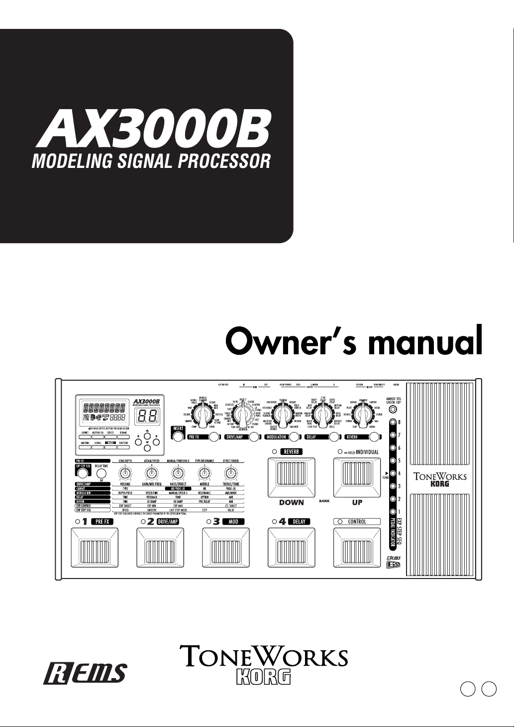
A Bassist’s Guided Panel Tour
Here we’re going to learn about the buttons and other controls on the AX3000B’s
top and rear panel.
F
RONT
PANEL
IntroductionPanel TourSetupPlayingCreating
and Storing
Effect TypePedals
E
FFECT
1.1 Effect Category buttons
Use these buttons to select the effect category you want to edit using value
knobs 1–5, or to switch individual effects on/off. The button for an effect will be
lit if that effect is on, blinking while that effect is being edited, or dark if that
effect is turned off.
EDIT
SECTION
3
ESS
MIDI/DIGITAL
Factory
settings
Trouble-
shooting
Spec. TunerAppendix
Index
Page 10

/
When you press a button, its LED will blink; now you can use value knobs 1–5
to edit the effect parameters of that category. If you want to turn off an effect
that is currently on, press the effect category button for that effect (it will blink),
and then press the button again to turn the effect off (the LED will go dark); the
display will indicate “--OFF--”.
1.2 Effect Model selectors
Use these to select the effect model that you want to use for each effect category. You can choose from eleven types of pre-effects, sixteen types of drive/
amp models, and eleven types of modulation, delay, and reverb effects. When
you operate a selector, its Effect Category button will light, and you can use
value knobs 1–5 to edit its parameters.
NOTE: The parameters will be initialized when you change the effect type.
NOTE: When you change the drive/amp model type, the cabinet model will auto-
matically change to an appropriate type.
1.3 INSERT button
This turns an insert effect on/off. The indicator will be lit if the signal input/output to an external effect device is turned on, or dark if this is turned off.
1.4 CABINET button
Use this button to turn a cabinet model on/off, or when you want to change the
cabinet model type that was automatically chosen when you selected a drive/
amp model. To turn the cabinet model off, press the cabinet model button to
make the display indicate the cabinet model name (this means that the cabinet
model is on), and then press the cabinet model button once again. The display
indicates “--OFF--” and the cabinet model will be turned off.
NOTE: The cabinet model is used only if the AMP/LINE setting is “Ln (LINE)” and
the drive/amp model is turned ON. In this state, the cabinet model will be used if it
is turned ON, and the cabinet icon will appear in the LCD display.
1.5 NR/PROG LVL (Noise reduction/Program level) button
Use this button when you want to adjust the noise reduction or the level (volume) of each program.
HINT: The factory program level is 5.0. For details on how to create your own
sounds, refer to “Creating your own Program” on p.17.
1.6 EXP/CTL (Expression/Control) pedal assignment button
Use this button when you want to change the assignment of the expression
pedal or control switch.
HINT: For details, refer to “Using the expression pedal to control parameters” on
p.41.
1.7 RENAME button
Use this to change the program name (p.19).
√√
®®
√√
Use the
use value knob 1 or the ▲ / ▼ buttons to change the character at that space.
®®
buttons to move between spaces (characters) in the display, and
4
Page 11

P
ARAMETER
2.1 Value knobs 1–5
Use these knobs to adjust the parameters of each effect. From the left, we
refer to these as value knobs 1–5. These knobs edit the settings of the effect
you’ve selected from an effect category button (when the button is blinking), as
well as the settings for the cabinet, noise reduction, program level, expression
pedal, ESS, and control switch settings. The LEDs will light to indicate the
knobs that are currently active.
The knob LED will change to blinking for the parameter that you’re currently
operating.
HINT: For details on the parameters controlled by each knob, refer to “Explanations
of the Effect Types” on p.23.
NOTE: When you’re performing a RENAME or WRITE operation or making GLO-
BAL settings, you can use value knob 1 to change the value.
E
DIT
SECTION
IntroductionPanel TourSetupPlayingCreating
and Storing
Effect TypePedals
2.2 Delay Time Tap button
You can set the delay time by pressing this button at the desired interval.
2.3 ESS button
Use this button when you want to start or make settings for the ESS (Expression Step Sequencer).
HINT: For details, refer to “Using ESS to control a parameter” on p.47
T
HE
P
ROGRAM
W
RITE
/E
XIT
SECTION
AND
O
THER
SETTINGS
5
ESS
MIDI/DIGITAL
Factory
settings
Trouble-
shooting
Spec. TunerAppendix
Index
Page 12
3.1 AMP/LINE button
This button lets you make appropriate settings for the device to which your
AX3000B is connected. The icon in the display will change depending on
the destination device you’ve selected (p.12).
3.2 GLOBAL button
√√
You can press the GLOBAL button and use the √√
the menus in the following order. After you’ve selected a menu item, use value
knob 1 or the
MIDI CH: MIDI channel setting (p.51)
PCHG OUT: Program change message output setting (p.51)
CCHG I/O: Control change message input/output setting (p.51)
SYEX OUT: System exclusive message output setting (p.52)
DUMP CUR: Send the current program data from the MIDI OUT jack (p.53)
DUMP ALL: Send all of the AX3000B’s data from the MIDI OUT jack (p.53)
DOUT LVL Set the S/P DIF output level in a range of five levels;
buttons to edit the value.
–12, –6, 0, +6, +12 [dB]
®®
®®
buttons to move through
/
▲ / ▼
3.3 WRITE button
Use this button when you want to save the settings you’ve created (p.19).
3.4 EXIT/TUNE button
Use this button to cancel a “program save” operation or a setting you
If the name display shows a program name, pressing this button will start up the
built-in Tuner. By pressing and holding down this button, you can enable or disable the Key Lock function, which disables operation of the buttons, selectors,
and knobs (p.16, 21).
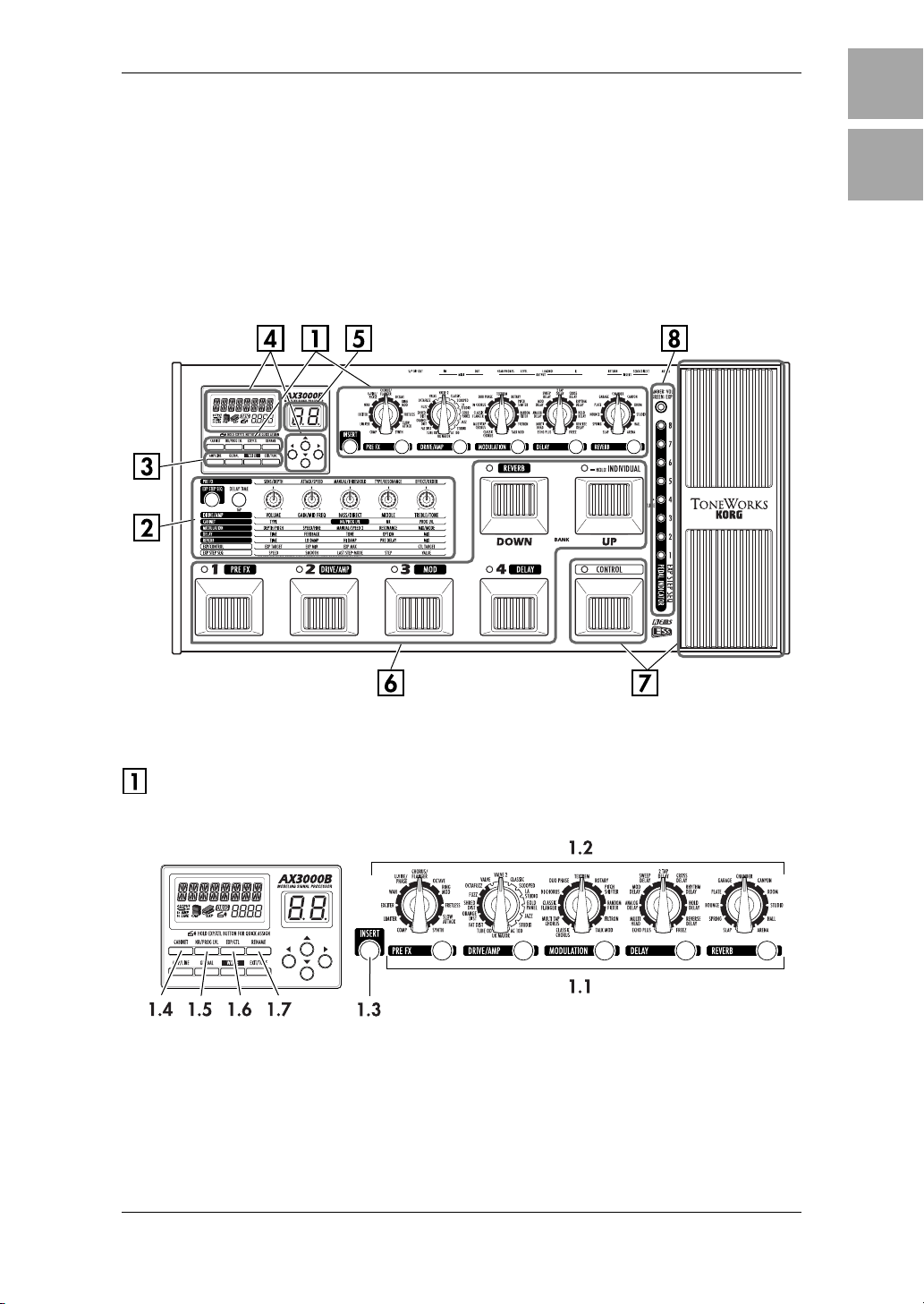
D
ISPLAY/CURSOR SECTION
’
ve made.
This area displays the program name, and the name and value of the parameters you’re editing in the amp or effect section.
4.1 ▲/▼ buttons
Use these to edit the value of parameters.
6
Page 13
4.2 √√√√/®®®® buttons
Use these to select the parameter you want to edit, or to edit the program
name.
4.3 Name display
Displays program names, effect names, or parameter names.
4.4 Value display
This indicates the value of the parameter you are editing. If the displayed
parameter value matches the unedited value (i.e., the value that’s stored in the
program), the Original Value icon will light. If the name display shows the
program name, and the program name or BANK LED are not blinking, the
bank number and program number are shown in the form of “2-1” (which in this
example indicates bank 2, program 1).
4.5 OUTPUT icon
This indicates the AX3000B’s output destination setting (AMP/LINE).
4.6 CABINET icon
This will light when the Cabinet model is active.
4.7 EXP icon
This will light when the expression pedal can be used.
IntroductionPanel TourSetupPlayingCreating
and Storing
4.8 Quick Assign icon
This will light if you’re operating a parameter that can be assigned to the
expression pedal, indicating that the Quick Assign function is available.
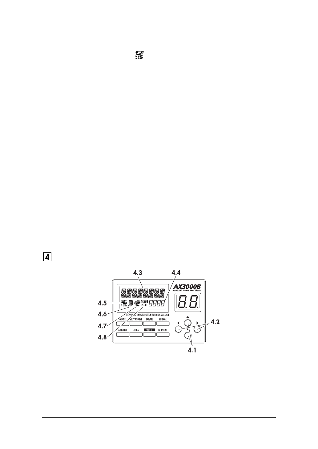
BANK DISPLAY
5.1 Bank display
This indicates the bank number. If the Tuner is operating, it indicates the note
name (p.21).
Effect TypePedals
ESS
MIDI/DIGITAL
Factory
settings
Trouble-
shooting
Spec. TunerAppendix
7
Index
Page 14
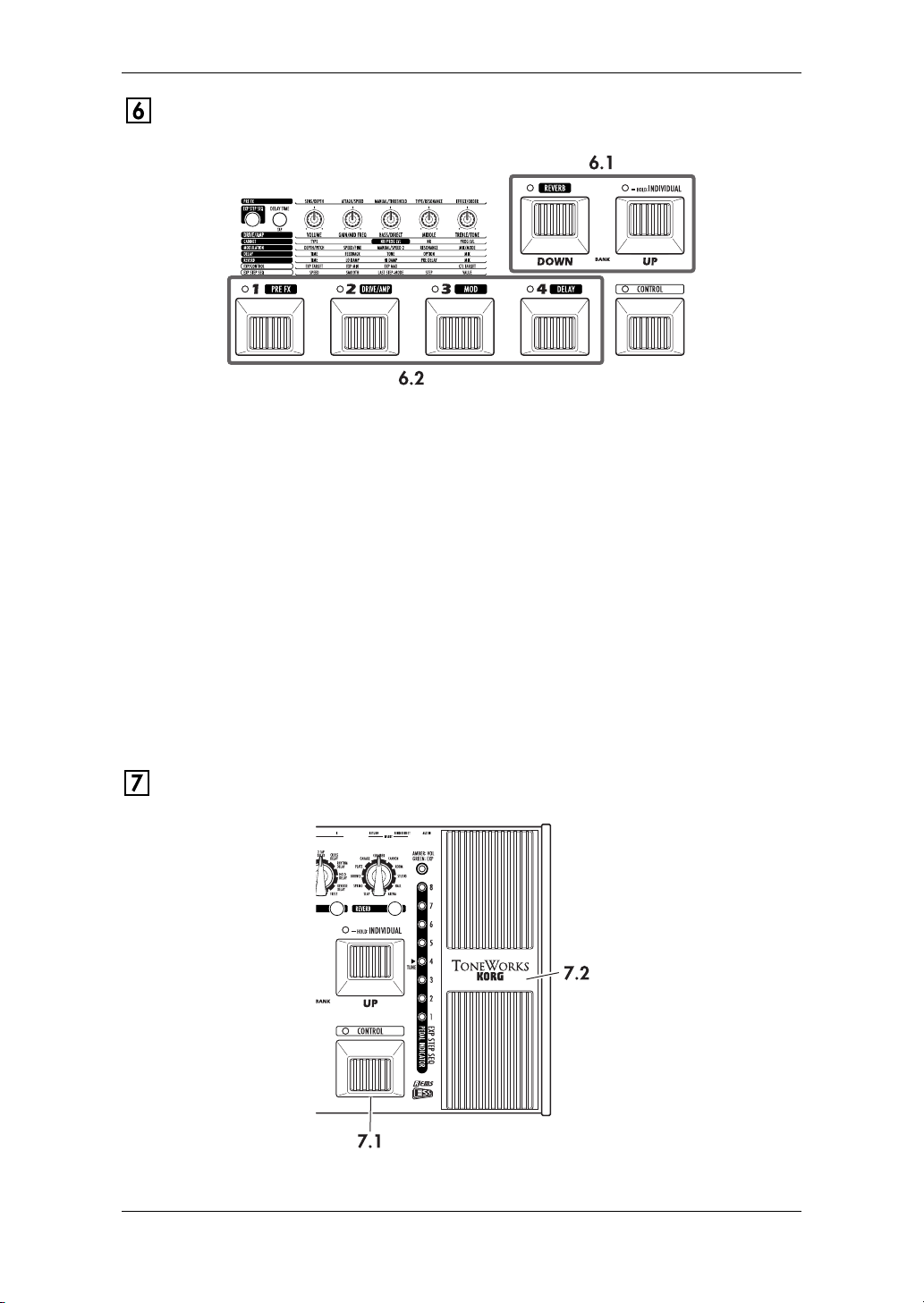
BANK/PROGRAM SELECT SECTION
6.1 BANK UP/DOWN switches
In Program Select mode (p.15), pressing Bank Up will increment the bank, and
pressing Bank Down will decrement the bank.
In Program Select mode, you can press and hold the Bank Up switch which
turns on Individual mode (the LED located at the upper left of the switch will
light green). In Individual mode, you can use the program select switches to
turn the Pre-Effect, Drive/Amp model, Modulation effect, and Delay effect on/
off individually. You can also use the Bank Down switch to turn the Reverb
effect on/off.
6.2 Program Select switches, Program LEDs
Use these switches to select programs. The program LED located at the upper
left of each switch will light red to indicate your selection. In Individual mode,
you can use these switches to turn the Pre-Effect, Drive/Amp model, Modulation effect, and Delay effect on (LED lit green) or off individually.
EFFECT CONTROL SECTION
8
Page 15
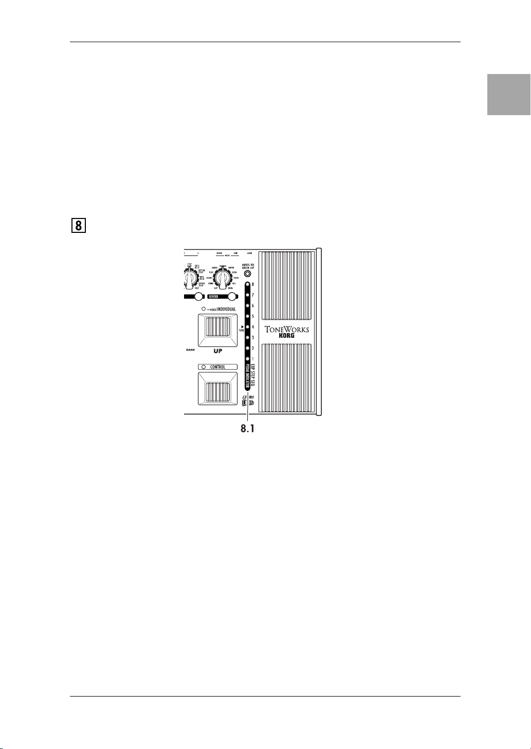
7.1 CONTROL switch
This switch controls an effect. For each program, you can assign what effect
parameter this switch will control. For details, refer to “Control switch settings”
on p.44.
7.2 EXP (Expression) pedal
This controls volume, wah, or another effect parameter. For each program, you
can assign just what this pedal will control (p.41). When using ESS, manual
control of the sequence speed or step is assigned to this pedal. By advancing
this pedal forward to press the switch that’s mounted under it, you can turn the
expression pedal or the effect being controlled by ESS on/off. (This switching
operation is not available if the EXP pedal is controlling the volume.)
ESS/PEDAL INDICATOR/TUNER DISPLAY
IntroductionPanel TourSetupPlayingCreating
and Storing
Effect TypePedals
8.1 ESS/Pedal indicator/Tuner display
When you’re using ESS, this indicates the total number of steps (LED: green)
and the current step (LED: red). When you’re using the expression pedal, this
indicates the current position of the pedal (LED: red). When the Tuner is operating, this functions as a tuning meter (LED: red or green).
NOTE: What happens when you change programs will depend on the target that’s
assigned to the expression pedal, as follows.
If the expression pedal is assigned to VOLUME, DELAY INPUT, or REVERB
INPUT, or if it is assigned to the same target as in the previous program, the pedal
position will be valid immediately after the program change, and the pedal indicator
will light.
In other cases, the value specified within the program will be valid immediately
after the program change, and the pedal indicator will be dark until you move the
pedal.
9
ESS
MIDI/DIGITAL
Factory
settings
Trouble-
shooting
Spec. TunerAppendix
Index
Page 16
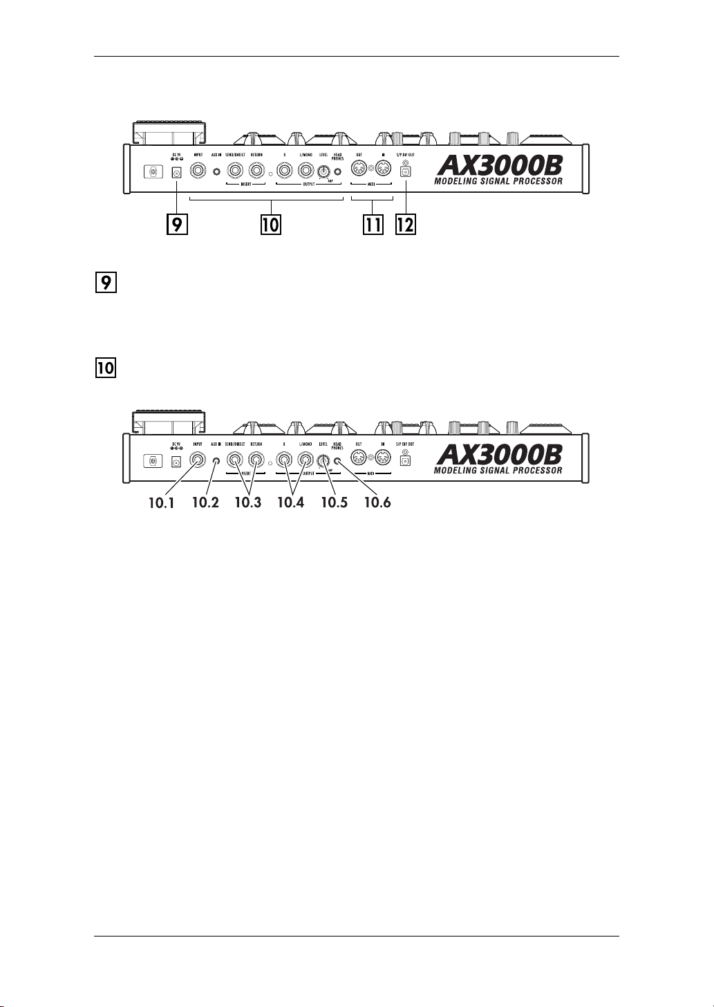
REAR PANEL
POWER SUPPLY
DC9V
Connect the included AC adapter here.
INPUTS AND OUTPUTS
10.1 INPUT jack
Connect your bass to this jack.
10.2 AUX IN jack (stereo mini)
Connect the analog output of your audio device here.
NOTE: This convenient input jack lets you connect your CD/MP3 player or other
audio device and play your bass along with a favorite song. Use the output volume
of your audio device to adjust the playback volume.
10.3 INSERT jacks (SEND, RETURN)
You can connect external effect processors or stompboxes to these jacks.
Connect SEND to the input of your external effect device.
Connect RETURN to the output of your external effect device.
HINT: The incoming sound is always output from the SEND jack.
HINT: If a 1/4" phone plug is connected to the RETURN jack, the signal received at
the RETURN jack will be processed if INSERT is ON. If nothing is connected to the
RETURN jack, the signal received at the INPUT jack is always used.
10.4 OUTPUT jacks (L/MONO, R)
These are analog output jacks (balanced/unbalanced TRS). If you’re using a
mono output, use the L/MONO jack.
10
Page 17
10.5 LEVEL knob
Adjusts the output level from the OUTPUT jacks and the PHONE jack.
10.6 PHONE jack (stereo mini)
Connect your headphones to this jack.
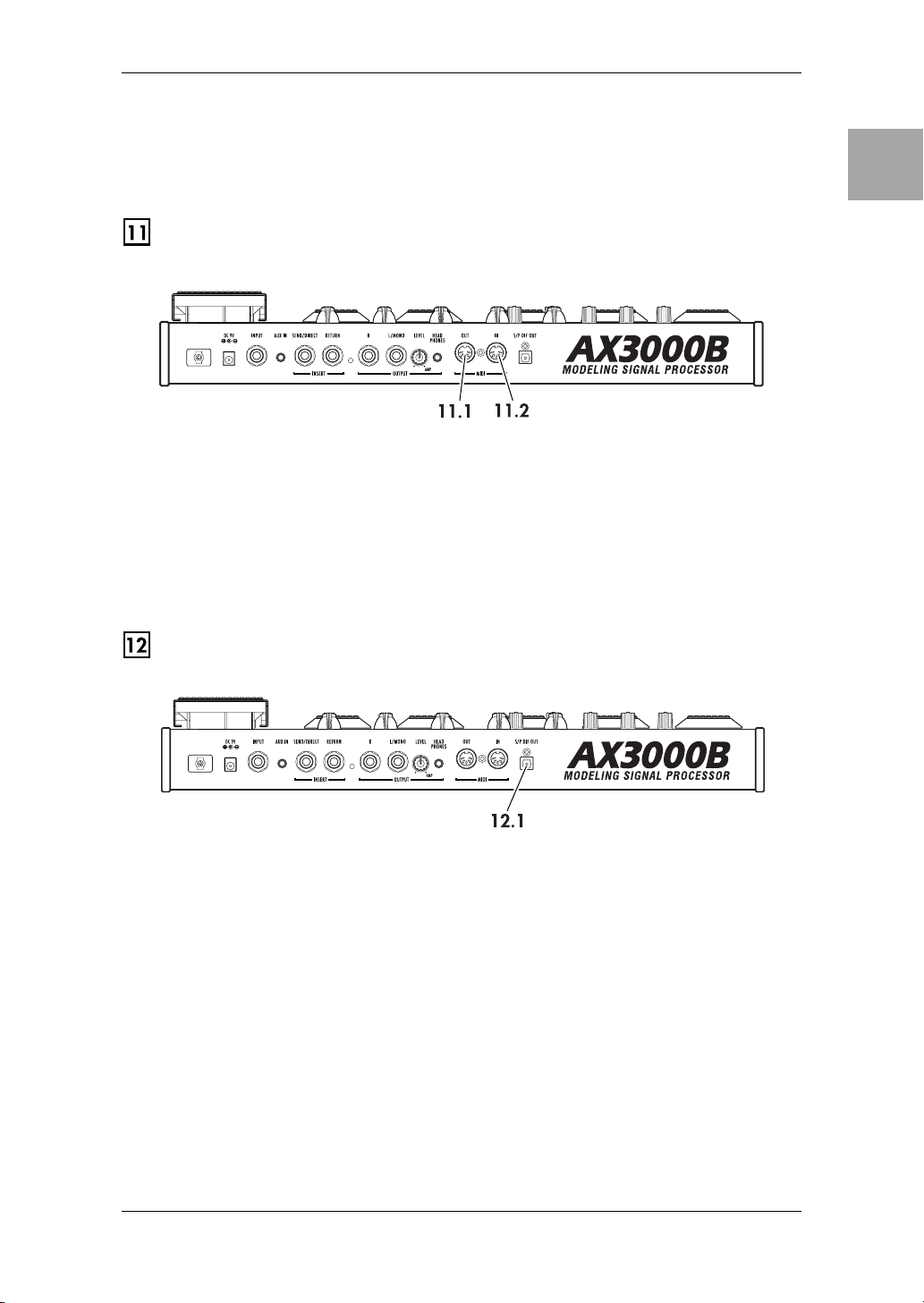
MIDI
11.1 MIDI OUT jack
This jack transmits MIDI data. Use it when you want to control a connected
external MIDI device from your AX3000B.
11.2 MIDI IN jack
This jack receives MIDI data. Use it when you want to control your AX3000B
from a connected external MIDI device.
IntroductionPanel TourSetupPlayingCreating
and Storing
Effect TypePedals
S/P DIF OUT
12.1 S/P DIF OUT jack
This is an optical digital jack for S/P DIF output.
ESS
MIDI/DIGITAL
Factory
settings
Trouble-
shooting
Spec. TunerAppendix
11
Index
Page 18
Setup
NOTE: You must turn off the power of all your equipment before you make connections. If you ignore this warning, you may damage your bass amp or speaker system, and may experience malfunctions!
OUTPUT SETTINGS
OUTPUT SELECT FUNCTION
Here’s how to specify whether you’re connecting the AX3000B to a bass amp or to
a mixer/recorder. If you set the output select setting to “Ln (Line),” the cabinet
model setting is ignored. The cabinet model setting is also ignored when the drive/
amp model is OFF, and won't be affected by this setting.
1. Press the AMP/LINE button.
2. Use Value knob 1 or the ▲/▼ buttons to select the connection destination.
AP: When connecting the AX3000B’s output to an amp.
Ln: When connecting the AX3000B’s output (including S/P DIF OUT) to a
mixer, recorder, or headphones.
If you choose AP, the LCD display will show the OUTPUT icon “to AMP.” If
you choose Ln, the OUTPUT icon “to LINE” will appear.
NOTE: Use the “Ln (LINE)” setting if you're connecting the AX3000B to a bass amp
that has a broad frequency response, such as a bass amp with a built-in tweeter.
BASIC CONNECTIONS
1. Use audio cables to connect the AX3000B’s OUTPUT L/MONO and R jacks to
a mixer/recorder or bass amp (p.14). If desired, you can also connect an external effect processor. To do this simply connect SEND to the input of your external processor, and RETURN to the output of your external processor.
NOTE: If you’re making connections in mono, use the OUTPUT L/MONO jack.
If you connect only the OUTPUT L/MONO jack, only the L-channel of sound will be
output.
NOTE: If you want to use headphones, plug them into the PHONES jack. If you do,
signal from the OUTPUT jack(s) will no longer be heard.
2. Turn the LEVEL knob located on the rear panel of AX3000B all the way toward
the left (as seen from the rear), setting the volume to 0.
3. Plug your bass into the rear panel INPUT jack.
4. Connect the included AC adaptor to the rear panel DC9V power inlet, and then
connect the plug to an AC outlet to turn on the power.
12
Page 19

5. To adjust the volume, turn up your amp or mixer and the AX3000B’s rear panel
LEVEL knob to a desired level.
NOTE: Use the GLOBAL menu setting “DOUT LVL” to adjust the S/P DIF OUT output level.
External effect processor
to your mixer/recorder
or guitar amp
LINE/AMP
Headphones
IntroductionPanel TourSetupPlayingCreating
to your MIDI
sequencer/computer
Bass
Monaural phone
jack INPUT
INPUT
SEND
RETURN
OUTPUT
L/MONO
R
PHONES
EXAMPLE OF CONNECTION TO A BASS AMP (OR AMPS)
• If you want to connect the AX3000B to your bass amps, connect the OUTPUT
L/MONO and R jacks to the inputs of your amps. Be sure to select the appropriate connection (p.12).
HINT: If you’re connecting the AX3000B directly before your combo amp or head,
set the rear panel LEVEL knob to the maximum position.
Bass
Monaural phone jack
INPUT
OUTPUT
L/MONO
INPUT
Monaural
phone jack
and Storing
Effect TypePedals
ESS
MIDI/DIGITAL
13
Bass amp(s)
Factory
settings
Trouble-
shooting
Spec. TunerAppendix
Index
Page 20
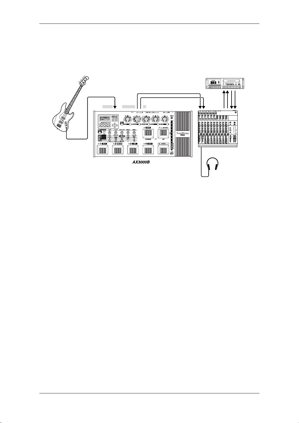
EXAMPLE OF CONNECTIONS TO A MIXER OR RECORDER
• When using the AX3000B for direct-line recording, connect the OUTPUT L/
MONO and R jacks to the input jacks of your mixer or recorder. Be sure to select
the appropriate connection (p.12).
Bass
Monaural phone jack
INPUT
OUTPUT
L/MONO
Tape
Send
R
LINE IN 1
PAN L
MIC
LINE IN 1
1
-
C
I
M
U
10
+
10dB
TRIM
U
+15
U
+15
U
-15
+15
U
-12
+12
U
+15
-15
L
R
1
MUTE
ALT 3–4
dB
10
5
U
5
10
20
30
40
50
60
MIC
1
BAL
OR
UNBAL
LINE IN 2
LOW CUT
75Hz
18dB/OCT
B
d
d
V
0
0
1
-
G
G
A
I
C
N
I
M
U
10
60
+
10dB
-40dB
TRIM
U
AUX
1
MON/
EFX
+15
U
2
EFX
+15
U
EQ
-15
+15
U
MID
2.5kHz
-12
+12
U
LOW
80Hz
+15
-15
PAN
L
R
2
MUTE
ALT 3–4
dB
10
SOLO
5
U
5
10
20
30
40
50
60
LINE IN 2
PAN R
MIC
MIC
3
2
BAL
BAL
OR
OR
UNBAL
UNBAL
LINE IN 4
LINE IN 3
LOW CUT
LOW CUT
75Hz
75Hz
18dB/OCT
18dB/OCT
B
d
B
V
V
1
0
-
1
-
G
A
C
A
I
I
C
I
N
N
I
M
M
U
U
10
10
60
60
+
10dB
+
10dB
-40dB
-40dB
TRIM
TRIM
U
U
AUX
AUX
1
1
MON/
MON/
EFX
EFX
+15
+15
U
U
2
2
EFX
EFX
+15
+15
U
U
EQ
EQ
-15
+15
-15
+15
U
U
MID
MID
2.5kHz
2.5kHz
-12
+12
-12
+12
U
U
LOW
LOW
80Hz
80Hz
+15
-15
+15
-15
PAN
PAN
L
R
L
R
4
3
MUTE
MUTE
ALT 3–4
ALT 3–4
dB
dB
10
10
SOLO
SOLO
5
5
U
U
5
5
10
10
20
20
30
30
40
40
50
50
60
60
4
MIC
6
MIC
5
BAL
BAL
BAL
MONO
OR
OR
OR
UNBAL
UNBAL
UNBAL
L
LINE IN 6
LINE IN 5
BAL
LOW CUT
OR
LOW CUT
LOW CUT
75Hz
75Hz
75Hz
UNBAL
18dB/OCT
18dB/OCT
18dB/OCT
B
d
V
0
B
B
d
d
V
V
0
0
1
1
-
-
R
G
A
G
A
G
A
I
N
I
C
I
C
N
N
I
I
M
M
U
U
LEVEL
+4
60
10
10
60
60
-10
-40dB
+
10dB
-40dB
+
10dB
-40dB
LINE IN 7-8
TRIM
TRIM
U
U
U
AUX
AUX
AUX
AUX
1
1
1
1
MON/
MON/
MON/
MON/
EFX
EFX
EFX
EFX
+15
+15
+15
U
U
U
2
2
2
2
EFX
EFX
EFX
EFX
+15
+15
+15
U
U
U
EQ
EQ
EQ
EQ
-15
+15
-15
+15
-15
+15
U
U
U
MID
MID
MID
MID
2.5kHz
2.5kHz
2.5kHz
2.5kHz
-12
+12
-12
-12
+12
+12
U
U
U
LOW
LOW
LOW
LOW
80Hz
80Hz
80Hz
80Hz
+15
-15
+15
+15
-15
-15
PAN
PAN
PAN
PAN
L
R
L
L
R
R
6
7–8
5
MUTE
MUTE
MUTE
ALT 3–4
ALT 3–4
ALT 3–4
dB
dB
dB
10
10
10
SOLO
SOLO
SOLO
SOLO
5
5
5
U
U
U
5
5
5
10
10
10
20
20
20
30
30
30
40
40
40
50
50
50
60
60
60
PHONES
MONO
MONO
MONO
L
L
L
BAL
BAL
BAL
OR
OR
OR
UNBAL
UNBAL
UNBAL
R
R
R
LEVEL
LEVEL
LEVEL
+4
+4
+4
-10
-10
-10
LINE IN 13-14
LINE IN 9-10
LINE IN 11-12
U
U
U
U
AUX
AUX
AUX
1
1
1
MON/
MON/
MON/
EFX
EFX
EFX
+10
+15
+15
+15
U
U
U
AUX 1 MASTER
2
2
2
EFX
EFX
EFX
AUX 1
+15
+15
SELECT
+15
U
U
U
EQ
EQ
EQ
-15
+15
-15
+15
-15
+15
U
U
U
ALT
3-4
MID
MID
MID
2.5kHz
2.5kHz
2.5kHz
-12
-12
+12
-12
+12
+12
TAPE
U
U
U
LOW
LOW
LOW
80Hz
80Hz
80Hz
+15
+15
-15
+15
-15
-15
PAN
PAN
PAN
NORMAL(AFL)
LEVEL SET(PFL)
L
R
L
L
R
R
SOLO
MODE
9–10
13–14
11–12
MUTE
MUTE
MUTE
POWER
PHANTOM
ALT 3–4
ALT 3–4
ALT 3–4
CONTROL
/ PHONES
ROOM
dB
dB
dB
dB
10
10
10
10
SOLO
SOLO
SOLO
5
5
5
5
U
U
U
U
5
5
5
5
10
10
10
10
20
20
20
20
30
30
30
30
40
40
40
40
50
50
50
50
60
60
60
60
Mixer/recorder
U
+20
U
+20
LEFT RIGHT
+10
+7
+4
+2
0
-2
-4
-7
-10
-20
-30
0dB=0dBu
RUDE SOLO LIGHT
MAIN MIX
5
U
5
10
20
30
30
40
40
50
50
60
60
Tape
Retuen
PHONES
1
NORMALLED
2
AUX
RETURNS
CLIP+28
Headphones
USING THE AX3000B WITH A MIDI DEVICE OR
COMPUTER
By using MIDI you can control the AX3000B from a sequencer or control an external MIDI device from the AX3000B. You can also save the AX3000B’s programs on
a sequencer or MIDI data filer that is able to transmit and receive MIDI exclusive
data, and then load the program data back into the AX3000B when desired.
HINT: For details on MIDI-related connections, refer to “Connecting a MIDI Device
or Computer” on p.50.
14
Page 21

Playing the AX3000B
PROGRAM SELECT MODE
(LED at the upper left of the Bank Up switch is not lit)
Settings for each effect, the expression pedal, ESS, and other functions can be
given a name and stored in the AX3000B as a “program.” The AX3000B can hold
96 programs (24 banks x 4 programs in each bank), and all of these programs are
rewritable. When the AX3000B is shipped from the factory, banks 1–8 contain 32
preset programs. In Program Select mode you can switch between various types
of sounds by selecting the desired program.
HINT: Banks 9–16 and 17–24 contain the same preset programs as banks 1–8.
SELECTING A PROGRAM
As an example, here’s how to select program 2-3 (bank 2, program 3).
1. Make sure that your AX3000B is in Program Select mode.
If the LED located at the upper left of the Bank Up switch is lit green, Individual
Mode is selected. Press the Bank Up switch to choose Program Select mode.
If the bank display shows something other than a bank (1–24), or if the bank
display is blinking, press the EXIT/TUNER button to choose Program Select
mode.
IntroductionPanel TourSetupPlayingCreating
and Storing
Effect TypePedals
2. Press the Bank Up or Bank Down switch to select bank 2. When you’re select-
ing a bank, the bank number will blink in the bank display.
3. Press the program select 3 switch.
Program 2-3 will be displayed instantly. The program select 3 switch LED will
light, and the bank number will also change and stay lit.
HINT: When you’ve selected the Bank but not the Program, the previously-selected
program is still active. So if you’re playing live and your next program change
requires you to switch to a different bank, you can select that bank ahead of time,
ensuring a timely, seamless change.
INDIVIDUAL MODE
(LED at the upper left of the Bank Up switch is lit green)
In this mode you can individually turn each effect on/off just as if you were using a
collection of stompboxes. You can select Individual mode from any program.
ESS
MIDI/DIGITAL
Factory
settings
Trouble-
shooting
Spec. TunerAppendix
15
Index
Page 22

OPERATIONS IN INDIVIDUAL MODE
As an example, here’s how to switch the pre-effect and reverb on/off while you’re
playing.
1. If the LED at the upper left of the BANK UP pedal is dark, you're in Program
Select mode. Press and hold the BANK UP pedal for about one second to
enter Individual mode. At this time the LED at the upper left of the BANK UP
pedal will light green. Program LEDs 1–4 and the LED at the upper left of the
Bank Down switch will be lit green or dark to indicate the on/off status of the
pre-effect, drive/amp model, modulation effect, delay effect, and reverb effect
respectively.
2. Press the program select switch 1 to turn the pre-effect on/off. The LED 1 lit/
dark state indicates the on/off status of the pre-effect.
3. Press the Bank Down switch to turn the reverb on/off. The LED at the upper left
of the Bank Down switch will be lit or dark to indicate the reverb’s on/off state.
4. To exit Individual mode, press the BANK UP pedal. The LED at the upper left
of the BANK UP pedal will go dark.
ACTIVATING OR DEACTIVATING THE KEY LOCK FUNCTION
Here’s how you can use the Key Lock function to disable the AX3000B’s buttons,
selectors, and knobs so they can’t be accidentally changed during a live performance.
NOTE: While the Key Lock function is activated, you won’t be able to operate any
controls except for the switches, pedals and the EXIT button.
NOTE: The Key Lock setting is cancelled when you turn off the power; it will be disabled when you turn on the power once again.
ACTIVATING THE KEY LOCK FUNCTION
1. If the name display shows anything other than a program name, or if the characters of the program name are blinking, press the EXIT button.
2. With the program name shown in the name display, press and hold the EXIT
button for at least one second.
The name display will indicate “KEY LOCK” for one second.
DEACTIVATING THE KEY LOCK FUNCTION
1. If the name display shows anything other than a program name, press the
EXIT button.
2. Press and hold the EXIT button for at least one second.
The name display will indicate “LOCK OFF” for one second, and the Key Lock
function will be disabled.
16
Page 23

Creating and Storing your own Programs
SIGNAL PATH
IntroductionPanel TourSetupPlayingCreating
Input
There are two ways you can do this; by “tweaking an existing program” or by “start-
ing from scratch.”
Insert effect Pre-effect Drive/amp cabinet
ReverbAmp/line selectOutput
Delay
Modulation
CREATING YOUR OWN PROGRAM
If you want to tweak an existing program, select one that’s close to the sound you
want. Set the CATEGORY select switches to the amp, cabinet and effects you
want to use, and use value knobs 1–5 to adjust the sound.
For example, you might start with an old-style bass sound that has rich mid- and
low-frequencies, and create a more contemporary "scooped" bass sound by lowering the mids and boosting the highs.
Now here’s how to create your own program from scratch.
NOTE: Before you proceed, you must first perform the setup procedure described
on
p.12 to correctly specify the type of equipment to which your AX3000B is con-
nected.
1. Select any program (p.15).
HINT: It doesn’t matter which program you select, because we’re starting from
scratch.
2. In the PRE FX, MODULATION, DELAY, or REVERB section, press all category
select switches that are lit two times. This will turn off (bypass) all effects
except the amp and cabinet models.
and Storing
Effect TypePedals
ESS
MIDI/DIGITAL
Factory
settings
3. Use the DRIVE/AMP selector to select the drive/amp model you want to use.
4. Use value knobs 1–5 to adjust the parameters of the drive/amp model as
desired.
HINT: Adjust the VOLUME so that there’s not too much difference in volume when
the drive/amp model is switched on/off. If VOLUME is raised excessively, distortion
may occur in the effects located after drive/amp.
5. When you choose an amp model, the appropriate cabinet model will be
selected automatically. If you want to use the cabinet model (for example if the
AX3000B is connected to a mixer or recorder), press the CABINET button to
turn it on. If you use the cabinet model, make sure to choose the correct Out-
17
Trouble-
shooting
Spec. TunerAppendix
Index
Page 24

put Select setting (p.12). If you want to change the cabinet model, turn value
knob 1. If you don’t want to use a cabinet model, press the CABINET button
once again to turn it off; the icon will disappear from the LCD display.
6. Press the NR/PROG LVL button, and adjust NR (value knob 4) so that you
don’t hear noise when you’re not playing your bass. The effect will become
stronger as you increase the noise reduction setting (0.2, 0.4–10.0). If this is
off, no noise reduction is applied.
HINT: Depending on the bass you’re using, raising the noise reduction excessively
may cause notes to be cut off prematurely or to be delayed. Adjust the setting so
that your playing doesn’t feel unnatural.
7. In each section, choose the effect you want to use. For example if you want to
add spring reverb, use the REVERB selector to select SPRING.
HINT: At this time, the reverb model will automatically be turned on, and the LEDs
below the value knobs for each reverb parameter will light. For example, the parameters for SPRING are TIME, LO DAMP, HI DAMP, PRE DLY, and MIX, which are
controlled by value knobs 1–5 respectively.
8. To adjust the reverb mix amount, use value knob 5 which controls the MIX
parameter.
In the same way for PRE FX, MODULATION, and DELAY effects, use the
selector to choose an effect and the value knobs to adjust the parameters.
9. If you want to use an external device that’s connected to the insert effect jacks,
press the INSERT switch to turn on the signal route to your external device.
HINT: In some cases, it may be easier to adjust PRE FX or an insert effect while
listening to the original sound unprocessed by the modulation, delay, and reverb
effects. When using PRE FX or an insert effect, make the desired amp and cabinet
settings first, and then adjust your PRE FX or insert effect settings before the
remaining effects.
NOTE: For some models, the name of the parameter will differ from the names
printed in the parameter lines of the edit section. The actual name is shown in the
display when you turn the value knob. For details on the parameters, refer to
“Explanations of the Effect Types” on p.23.
10. Press the NR/PROG LVL button, and adjust PROG LVL (value knob 5) so that
the volume is consistent with other programs. Some effect settings may cause
clipping (distortion) to occur, so lower the PROG LVL if this happens.
NOTE: The factory program level setting is 5.0.
11. If you want to continue making adjustments, simply press the select button for
the model you want to edit, and turn the value knobs.
18
Page 25

NAMING A PROGRAM (RENAME)
Here’s how you can name a program.
NOTE: The program name is saved as part of each program. If you switch to a different program or turn off the power before you save, your settings will be lost.
1. Press the RENAME button.
2. Use the √√√√/®®®® buttons to move the cursor to the character you want to change
(the selected character blinks), and use value knob 1 or the ▲/▼ buttons to
change the character.
You can use the following characters.
3. Repeat step 2 to finish entering a name for your program.
4. When you’ve finished entering a name, press the EXIT button to return to the
mode you were in.
IntroductionPanel TourSetupPlayingCreating
and Storing
STORING A PROGRAM
When your tweaking has resulted in a sound you’re happy with, store (write) it!
1. Press the WRITE button.
The name display shows “*WRITE*” and the bank display and program LEDs
1–4 will blink.
2. Use value knob 1 or the ▲/▼ buttons to select the bank you want to use, and
use the √√√√/®®®® buttons to select the destination program 1–4.
For example if you want to store your program in 9-1 (bank 9, program 1), use
value knob 1 or the ▲/▼ buttons to make the bank display show “9,” and then
use the √√√√/®®®® buttons to make the program 1 switch LED blink.
HINT: You can also select the store-destination program by using the BANK UP/
DOWN switches or the program 1–4 select switches.
3. Press the WRITE button once again.
The program will be saved, the name display will indicate “COMPLETE,” and
you will return to Program Select mode.
NOTE: The program writes over the previous contents of that bank/program. The
program that previously occupied the number you selected in step 2 will be erased.
NOTE: If you decide not to store your new program, press the EXIT button to cancel the procedure.
NOTE: If you switch to a different program or turn off the power without storing the
program you edited, your changes will be lost.
Effect TypePedals
ESS
MIDI/DIGITAL
Factory
settings
Trouble-
shooting
Spec. TunerAppendix
19
Index
Page 26

RESTORING A SETTING TO ITS ORIGINAL VALUE
(O
RIGINAL VALUE)
The Original Value icon in the value display gives you a way to find out the
parameter values that are stored in a program.
When you are using a knob or button to change the value of a parameter, the
ORIG (original value) icon will appear when the value you are adjusting
matches the “original value” stored in the program.
HINT: So, you’re flipping through the programs on your new AX3000B, and you
come across one you really like. It’s easy to find out exactly what settings are
dialed in to get such an awesome tone — just use this Original Value display feature!
20
Page 27

Tuner (Bypass, Mute)
For your convenience, the AX3000B contains an Automatic Chromatic Tuner. The
frequency of the middle “A” reference pitch can be adjusted (calibrated) over a
range of 438 Hz–445 Hz.
The Bypass (all effects turned off, including noise reduction) and Mute functions
are useful when you need to make settings on your bass amp, tune your instrument, or swap bass during a live performance. To activate Bypass or Mute, make
sure you’re in Program Select mode and proceed as follows.
To activate Bypass
Press and hold down the program select switch of the currently selected program
for about 0.5 seconds; all effects will be bypassed. The program LED will blink,
and the name display will show “BYPASS” for one second.
To activate Mute
Press and hold down the program select switch of the currently selected program
for about 1.5 seconds; the output will be muted. The program LED will blink rapidly,
and the name display will show “MUTE” for one second.
In either case, the Auto Chromatic Tuner will be activated. To defeat Bypass or
Mute, press any desired program select switch and you will return to Program
mode.
IntroductionPanel TourSetupPlayingCreating
and Storing
Effect TypePedals
TUNING PROCEDURE
1. To activate the Auto Chromatic Tuner, you can either activate Bypass or Mute,
or press the EXIT/TUNE button while the display shows the program name. If
the display does not show the program name, press the EXIT/TUNE button to
make the program name appear, and then press the EXIT/TUNE button once
again.
HINT: If you want to tune during a live performance, it’s a good idea to tune while
Muted.
2. Play a string on your connected bass, and the closest note name will appear in
the bank display. Note names are shown as follows.
C C# D D# E F F# G G# A A# B
ESS
MIDI/DIGITAL
Factory
settings
Trouble-
shooting
Spec. TunerAppendix
21
Index
Page 28

3. Tune your bass while watching the tuner display or the meter in the name display.
The pitch is flat The pitch is correct
Tuner display Tuner display Tuner display
Name display Name display Name display
The pitch is sharp
4. When you’ve finished tuning, press the EXIT/TUNE button once again or press
any desired program select switch.
HINT: If you exit the Tuner by pressing a program select switch, this will also switch
to the program you selected.
CALIBRATING THE TUNER
When you switch the AX3000B on, the built-in tuner is automatically calibrated to
A=440 Hz (a.k.a. “concert pitch”). If desired, you can recalibrate the tuner in the
range of A = 438 Hz–445 Hz.
• While the tuner is active, the value display shows the frequency of the reference
pitch. You can use the ▲/▼ buttons to calibrate this in the range of 438 Hz–445 Hz.
HINT: If you’ve recalibrated the tuner, remember that the setting will be automati-
cally reset to 440 Hz the next time you turn your AX3000B on.
22
Page 29

Explanations of the Effect Types
his section explains the AX3000B’s sixteen drive/amp models and eleven
pre-effects, cabinet models, modulation, delay, and reverb effects.
T
A. DRIVE/AMP MODELS
The drive/amp model you select here will change the character of the tone controls
and their placement within the circuitry, producing the response that’s unique to each
model. This choice also selects an appropriate cabinet model.
* : This indicates a parameter that you can control from the expression pedal.
DRIVE MODELS
This provides six types of popular drive pedal, tuned for bass. With the exception
of SHRED DIST, a DIRECT parameter has been added to each of these.
1. TUBE OD
This models an overdrive pedal housed in a garish, “seasick green” box, that is
considered an all-time classic due to the wonderfully warm tones it produces.
[1] “VOLUME” 0.0–10.0 * Adjusts the volume.
[2] “GAIN” 0.0–10.0 * Adjusts the gain.
[3] “DIRECT” 0.0–10.0 * Adjusts the volume of the direct signal.
[5] “TONE” 0.0–10.0 * Adjusts the tone.
2. FAT DIST
This models a pedal named after one of the most disliked rodents to ever walk the
planet! The result is a smooth distortion rich in harmonics.
The parameters are the same as for 1. TUBE OD.
3. ORANGE DIST (OR DIST)
This models a classic distortion unit manufactured in Japan and packaged in an
orange box.
The parameters are the same as for 1. TUBE OD.
4. SHRED DIST (SHRED DS)
This distortion resembles the sound produced by a large amp stack.
[1] “VOLUME” 0.0–10.0 * Adjusts the volume.
[2] “GAIN” 0.0–10.0 * Adjusts the gain.
[3] “BASS” 0.0–10.0 Adjusts the low-frequency tone.
[4] “MIDDLE” 0.0–10.0 Adjusts the mid-frequency tone.
DRIVE/AMPCABINETPRE EFFECT
MODULATION
DELAYREVERB Effect Type Tuner
23
Page 30

[5] “TREBLE” 0.0–10.0 Adjusts the high-frequency tone.
5. FUZZ
Retro, rude ‘n’ raw ... the name says it all.
The parameters are the same as for 1. TUBE OD.
6. OCTAFUZZ
This models a fuzz unit legendary for its savagely aggressive distortion. A pitch
one octave above will be added if you turn down the tone and play above the
twelfth fret.
The parameters are the same as for 1. TUBE OD.
AMP MODELS
7. VALVE
A tube amp with the ULTRA LO switch turned ON (recommended cabinet:
CLS8x10)
[1] “VOLUME” 0.0–10.0 * Adjusts the volume.
[2] “MID FREQ” 1–5 Adjusts the frequency of the mid-range.
[3] “BASS” -10.0–10.0 Adjusts the low-frequency tone.
[4] “MIDDLE” -10.0–10.0 Adjusts the mid-frequency tone.
[5] “TREBLE” -10.0–10.0 Adjusts the high-frequency tone.
8. VALVE2
A tube amp that’s ideal for rock (recommended cabinet: CLS8x10)
The parameters are the same as for 7. VALVE.
9. CLASSIC
A tube amp whose basic character changes according to the setting of the value
dial (recommended cabinet: COMBI)
The parameters are the same as for 7. VALVE.
10. SCOOPED
A typical amp for the sound of the 80's (recommended cabinet: MTL4x10)
The parameters are the same as for 7. VALVE.
11. LA STUDIO (LA STUD)
A typical amp for the LA sound (recommended cabinet: LA 4x10, LA 1x18)
The parameters are the same as for 7. VALVE.
24
Page 31

12. GOLD PANEL (GOLD PNL)
A modern amp with a distinctive gold panel, noted for its clean sound (recommended cabinet: MDN4x10)
The parameters are the same as for 7. VALVE.
13. JAZZ
A combo amp loved by jazz bassists (recommended cabinet: JAZ1x15)
The parameters are the same as for 7. VALVE.
14. STUDIO
A tube combo amp ideal for the Motown sound (recommended cabinet: STU1x15)
Parameters
[1] “VOLUME” 0.0–10.0 * Adjusts the volume.
[2] “GAIN” 0.0–10.0 * Adjusts the gain.
[3] “BASS” -10.0–10.0 Adjusts the low-frequency tone.
[4] “MIDDLE” -10.0–10.0 Adjusts the mid-frequency tone.
[5] “TREBLE” -10.0–10.0 Adjusts the high-frequency tone.
15. AC100
A 100 watt tube amp manufactured by Vox (recommended cabinet: AC 2x15)
[1] “VOLUME” 0.0–10.0 * Adjusts the volume.
[2] “GAIN” 0.0–10.0 * Adjusts the gain.
[3] “BASS” 0.0–10.0 Adjusts the low-frequency tone.
[4] “MIDDLE” 0.0–10.0 Adjusts the mid-frequency tone.
[5] “TREBLE” 0.0–10.0 Adjusts the high-frequency tone.
16. UK MAJOR
A 200 watt tube amp made in the UK (recommended cabinet: UK 4x15, UK 4x12)
The parameters are the same as for 15. AC100.
B. CABINET MODELS
The cabinet models are associated with the drive/amp models.
They will have an effect only if the drive/amp model is turned on. When you
change the type of drive/amp model, an appropriate cabinet model is selected
automatically.
You can change the cabinet model by pressing the CABINET button and turning
value knob 1. If you don't want to use the cabinet model, press the CABINET
switch twice to turn it off. The cabinet icon will disappear from the LCD display.
NOTE: The cabinet model is ignored if you've selected Amp (“AP”) as the connec-
tion destination setting (p.12).
DRIVE/AMPCABINETPRE EFFECT
MODULATION
DELAYREVERB Effect Type Tuner
25
Page 32

1. CLASSIC 8X10 (CLS 8X10)
A classic cabinet model with eight 10-inch speakers.
2. MODERN 4X10 (MDR 4X10)
A modern cabinet model with four 10-inch speakers.
3. LA 4X10
A model of the “LA sound” with four 10-inch speakers.
4. METAL 4X10 (MTL 4X10)
Models a cabinet with aluminum-coned four 10-inch speakers.
5. UK 4X12
Models a UK-made cabinet with four 12-inch speakers.
6. STUDIO 1X15 (STUD 1X15)
A model of a studio/combo cabinet with one 15-inch speaker.
7. JAZZ 1X15
Models a jazz/combo cabinet with one 15-inch speaker.
8. AC 2X15
A cabinet model for the AC100 with two 15-inch speakers.
9. UK 4X15
Models a UK-made cabinet with four 15-inch speakers.
10. LA 1X18
A model of the “LA sound” with one 18-inch speaker.
11. COMBI
Models a combination of one 12-inch speaker and one 18-inch speaker.
26
Page 33

C. PRE EFFECT
The pre-effect is located in front of the drive/amp model.
* : This symbol indicates a parameter that you can control from the expression
pedal.
1. COMP
The COMP effect is ideal when you want to play smooth and clean phrases at a
consistent volume, or when you want more sustain. It models a compressor pedal
that was popular for its percussive clean sound.
[1] “SENS” 1.0–10.0 * Adjusts the sensitivity. Turn the knob toward
the right to increase the amount of compression and sustain.
[5] “LEVEL” 0.0–10.0 * Adjusts the output level.
2. LIMITER
This models an effect that maintains a consistent level for the input signal volume.
While it is similar to a compressor, a limiter applies compression only to the
sounds that exceed a specified level. Since raising the RATIO or lowering the
THRESHOLD will lower the overall level, you should use the LEVEL parameter to
compensate the level appropriately.
[1] “RATIO” 0.0–10.0 * Increasing the value will apply more com-
pression.
[2] “AT TAC K ” 0.0–10.0 * Increasing the value will cause compression
to apply more slowly.
[3] “THRESHLD”1.0–10.0 Compression will apply when the signal
exceeds the threshold level you specify
here.
[5] “LEVEL” 0.0–10.0 * Output level.
DRIVE/AMPCABINETPRE EFFECT
3. EXCITER
This models an effect that adds a brilliant high range to the sound. You can choose
from two types; a conventional exciter that always adds the high range, or a
“dynamic exciter” unique to ToneWorks which applies the exciter according to the
volume of the input (especially good on slapped bass playing).
[3] “FREQ” 1.0–10.0 * The frequency at which the exciter is
applied.
[4] “TYPE” Selects the type of exciter.
1 (Normal): Normal type
2 (Dyna): Dynamic type
[5] “EFFECT” 0.0–10.0 * Effect level.
27
MODULATION
DELAYREVERB Effect Type Tuner
Page 34

4. WAH
This models a wah pedal with a white body, designed for bass and featuring
adjustable resonance. Raising the RESO may cause distortion. You can lower the
TRIM parameter until distortion no longer occurs.
[1] “TRIM” 1.0–10.0 Trim (adjusts the level appropriately for the
setting of the RESO parameter).
[2] “OPEN” 1.0–10.0 Adjusts the maximum value for the open
position of the wah.
[3] “MANUAL” 1.0–10.0 * Adjusts how far the wah is open.
[4] “RESO” 0.0–10.0 * Adjusts the amount of resonance.
[5] “ORDER” Selects the connection order.
PrE(PRE): The wah is connected before the DRIVE/
AMP model.
PoS(POST): The wah is connected after the DRIVE/AMP
model.
HINT: When you select WAH, the expression pedal is automatically assigned to
“MANUAL.”
5. U-VIBE/PHASE (VIB/PHAS)
This lets you select one of three models; a famous phase/vibrato effect with a
pedal, a wide-range four-stage phaser that was made in Denmark and packaged
in a black box, and a popular four-stage phaser that came in a banana-colored
box. Use the TYPE to select the model.
[1] “DEPTH” 0.0–10.0 * Adjusts the vibrato/modulation depth.
[2] “SPEED” 0.1–10.0 [Hz] * Adjusts the vibrato/modulation speed.
[3] “MANUAL” 1.0–10.0 * Adjusts the center frequency of the sweep.
MANUAL has no effect if DEPTH is set to
10.0.
[4] “TYPE” Selects the type.
U-1: U-VIBE set to Vibrato mode.
U-2: U-VIBE set to Chorus mode.
Or: Models the popular four-stage phaser.
bL: Models the Danish phaser.
[5] “ORDER” Selects the connection order.
PrE(PRE): The effect is connected before the DRIVE/
AMP model.
PoS(POST): The effect is connected after the DRIVE/
AMP model.
HINT: If you assign the Speed to be controlled by the expression pedal, you’ll be
able to control the vibrato speed just as on the original phase/vibrato unit with
pedal that’s being modeled.
28
Page 35

6. CHORUS/FLANGER (CHO/FLNG)
This is a chorus/flanger unit with a standard circuit structure.
[1] “DEPTH” 0.0–10.0 * Adjusts the modulation depth.
[2] “SPEED” 0.1–10.0 [Hz] * Adjusts the modulation speed.
[3] “MANUAL” 1.0–10.0 * Adjusts the center frequency of the sweep.
MANUAL has no effect if DEPTH is set to
10.
[4] “RESO” 0.0–10.0 * Adjusts the amount of resonance.
7. OCTAVE
This models a pedal that generates a pitch one octave below the original input,
mixing it with the original sound to add thickness.
[4] “DIRECT” 0.0–10.0 * Adjusts the mix level of the original sound.
[5] “EFFECT” 0.0–10.0 * Adjusts the mix level of the note one octave
below.
HINT: This type of effect only works with single notes; chords will confuse it.
8. RING MOD
This is a ring modulator; an effect that uses an oscillator to generate a sine wave
which is then multiplied with the signal from your bass to produce new harmonics.
If you assign the OSCFREQ control to the expression pedal, you’ll be able to control the sound in unique ways while you perform.
[2] “FILTER” 1.0–10.0 * Adjusts the filter cutoff frequency.
[3] “OSCFREQ” 0.0–10.0 * Adjusts the oscillator frequency.
[4] “DIRECT” 0.0–10.0 * Adjusts the mix level of the original sound.
[5] “EFFECT” 0.0–10.0 * Adjusts the mix level of the effect sound.
DRIVE/AMPCABINETPRE EFFECT
9. FRETLESS
This effect transforms the sound of a fretted bass into that of a fretless bass.
[1] “DEPTH” 0.0–10.0 * Adjusts the degree of “fretlessness.”
HINT: This effect is designed for single-note playing. The sound may be muddy if
you play a chord.
10. SLOW ATTACK (SLOWATK)
This models a “slow attack” effect that slows down the attack of the bass to create
a violin-like impression.
[2] “AT TAC K ” 0.0–10.0 * Adjusts how the attack is modified.
29
MODULATION
DELAYREVERB Effect Type Tuner
Page 36

11. SYNTH
This models a bass synth. An algorithm unique to ToneWorks is used to simulate
an analog synthesizer sound with a smoothly tracking envelope filter.
[1] “DPTH/POL” -10.0–10.0 Adjusts the depth of the envelope filter (left
half is negative motion, right half is positive
motion).
[2] “AT TAC K ” 0.0–10.0 * Adjusts the attack of the envelope filter.
[3] “WAVE” 0.0–10.0 * Synth waveform.
The available choices model a variety from
an ordinary sawtooth waveform to a sawtooth
waveform one octave below.
[4] “RESO” 0.0–10.0 * Adjusts the resonance of the envelope filter.
[5] “MIX” 0.0–10.0 * Adjusts the mix balance between the original
sound and the synth sound.
HINT: This effect is designed for single-note playing. The sound may be muddy if
you play a chord.
HINT: The sound may be distorted depending on your settings and on how this
effect is combined with other effects. If so, you should lower the DRIVE/AMP [VOLUME] or the [PROG LVL] settings.
HINT: If you want to produce the overtone structure typical of a synthesizer, it is
sometimes best to turn off the CABINET model.
D. MOD (MODULATION) EFFECTS
Here you can select one of 11 modulation-type effects.
*: This indicates a parameter that you can control from the expression pedal.
1. CLASSIC CHORUS (CL CHORS)
This models a famous chorus unit with two modes; chorus and vibrato.
[1] “DEPTH” 0.0–10.0 * Adjusts the modulation depth.
[2] “SPEED” 0.1–10.0[Hz] * Adjusts the modulation speed.
[3] “MANUAL” 1.0–10.0 * Adjusts the center frequency of the sweep.
If DEPTH is set to 10, MANUAL will not func-
tion.
[5] “MODE” Selects the output mode.
1: Mono output.
2: Stereo mode in which the effect is panned
right, and the dry sound panned left.
3: Vibrato mode, in which only the effected
sound is output. Setting MANUAL to 10 will
minimize the delay of the output.
30
Page 37

2. MULTI TAP CHORUS (MT CHORS)
This is a chorus with independent taps for left/center/right, adding depth and spaciousness to your sound.
[1] “DEPTH” 0.0–10.0 * Adjusts the modulation depth.
[2] “SPEED” 0.1–10.0[Hz] * Adjusts the modulation speed.
[3] “TIME” 0.0–10.0 Adjusts the delay time.
[5] “MIX” 0.0–10.0 * Adjusts the mix level of the effect.
3. CLASSIC FLANGER (CL FLANG)
This models a classic analog flanger.
[1] “DEPTH” 0.0–10.0 * Adjusts the modulation depth.
[2] “SPEED” 0.1–10.0[Hz] * Adjusts the modulation speed.
[3] “MANUAL” 1.0–10.0 * Adjusts the center frequency of the sweep. If
DEPTH is set to 10, MANUAL will not func-
tion.
[4] “RESO” 0.0–10.0 * Adjusts the amount of resonance.
[5] “MIX” 0.0–10.0 * Adjusts the mix amount of the effect.
CONTROL switch
FLN TRIG If you set the FLN TRIG: CONTROL switch
setting to “FLN TRIG,” the LFO will be reset
to the position specified by OFFSET when-
ever you operate the switch.
switch settings)
(p.44 Control
4. BI CHORUS (BI CHORS)
This is a chorus model unique to the AX3000B. It provides two chorus units, CHORUS 1 and CHORUS 2, and lets you connect the two units not only in series or in
parallel, but also to synchronize or de-synchronize the two LFOs. It produces a
variety of tones that cover a range from wonderfully spacious sounds to bizarre
flanger-like sounds with complex modulation.
[1] “DEPTH” 0.0–10.0
[2] “SPEED 1” 0.1–10.0[Hz] * Adjusts the modulation speed of CHORUS 1.
[3] “SPEED 2” 0.1–10.0[Hz] * Adjusts the modulation speed of CHORUS 2.
NOTE: This will not function if MODE is set to P2 or P3.
[4] “RESO” 0.0–10.0 * Adjusts the amount of resonance for CHO-
[5] “MODE” Specifies the connection and LFO for CHO-
S: CHORUS 1/2 are connected in series.
P1: CHORUS 1/2 are connected in parallel.
P2: CHORUS 1/2 are connected in parallel, and
* Adjusts the modulation depth of CHORUS 1/2.
RUS 1/2.
RUS 1/2.
their LFOs are synchronized.
DRIVE/AMPCABINETPRE EFFECT
MODULATION
DELAYREVERB Effect Type Tuner
31
Page 38

P3: CHORUS 1/2 are connected in parallel, and
their LFOs are synchronized in opposite
phase (Stereo mode).
NOTE: If P2 or P3 is selected, the speed is adjusted by the SPEED 1 (value knob 2).
5. DUO PHASE (DUO PHAS)
This is an amazing phaser that provides two six-stage phasers; PHASER 1 and
PHASER 2. They can be connected in series (to make a pseudo-twelve-stage
phaser!) or in parallel, and you can also synchronize or de-synchronize the two
LFOs.
[1] “DEPTH” 0.0–10.0 * Adjusts the modulation depth of PHASER 1/2.
[2] “SPEED 1” 0.1–10.0[Hz] * Adjusts the modulation speed of PHASER 1.
[3] “SPEED 2” 0.1–10.0[Hz] * Adjusts the modulation speed of PHASER 2.
NOTE: This will not function if MODE is set to S2, P2, or P3.
[4] “RESO” 0.0–10.0 * Adjusts the amount of resonance for
PHASER 1/2.
[5] “MODE” Specifies the connection and LFO for
PHASER 1/2.
S1: PHASER 1/2 are connected in series.
S2: PHASER 1/2 are connected in series and
their LFOs are synchronized to create a
pseudo-twelve-stage phaser.
P1: PHASER 1/2 are connected in parallel.
P2: PHASER 1/2 are connected in parallel, and
their LFOs are synchronized (Stereo mode).
P3: PHASER 1/2 are connected in parallel, and
their LFOs are synchronized in opposite
phase (Stereo mode).
NOTE: If P2 or P3 is selected, the speed is adjusted by the SPEED 1 (value knob
2).
6. TEXTREM
This models an legendary tremolo circuit. You can adjust the SPREAD setting to
produce a panning effect that extends to left and right.
[1] “DEPTH” 0.0–10.0 * Adjusts the tremolo depth.
[2] “SPEED” 1.0–10.0[Hz] * Adjusts the tremolo speed.
[4] “SPREAD” 0.0–10.0 Adjusts the left/right spaciousness.
[5] “LEVEL” 1.0–10.0 * Compensates the output level.
32
Page 39

7. ROTARY
This models a stereo rotary speaker. When you adjust the speed, it will take a certain amount of time for the specified speed to be reached – just like on an actual
rotary speaker. This is because it takes several seconds for the motor that creates
the rotation to accelerate or decelerate.
[1] “DEPTH” 0.0–10.0 * Adjusts the modulation depth.
[2] “SPEED 1” 0.1–10.0[Hz] * Adjusts the rotational speed of the speaker. If
you assign “ROT SPD” to the CONTROL
switch, this will be the SLOW speed. This
knob is effective even if you’re not using the
CONTROL switch.
tings)
[4] “SPEED 2” 0.1–10.0[Hz] * Adjusts the rotational speed of the speaker. If
you assign “ROT SPD” to the CONTROL
switch, this will be the FAST speed. This
knob will not function if you’re not using the
CONTROL switch.
tings)
[5] “ACCEL” 1.0–10.0 * Adjusts the time it takes for the rotational
speed to change. With higher settings, the
change will take more time.
CONTROL
switch ROT SPD If you select “ROT SPD” as the CONTROL
switch setting, the rotation speed will alter-
nate between SLOW/FAST (SPEED 1/
SPEED 2) each time you press the CON-
TROL switch. This lets you control the effect
just as on an actual rotary speaker.
Control switch settings)
(p.44 Control switch set-
(p.44 Control switch set-
(p.44
DRIVE/AMPCABINETPRE EFFECT
8. PITCH SHIFTER (PITCH)
This is a pitch shifter with a range of two octaves up or down, rivaling sophisticated
rack-mounted signal processors.
[1] “PITCH”–24–+24 * Adjusts the pitch in semitone steps.
[2] “FINE”–50–+50 * Adjusts the pitch in one-cent units.
[3] “TRACKING”10–150 [ms] Adjusts the tracking of the pitch shifter (i.e.,
how closely it will follow). Shorter settings are
effective if the PITCH setting is close to 0,
and longer settings are effective if the PITCH
setting is close to +/–24. While listening to
the pitch-shifted sound, adjust this so that
playing is easier.
[4] “DIRECT” 0.0–10.0 * Adjusts the level of the direct sound.
[5] “EFFECT” 0.0–10.0 * Adjusts the level of the effect.
NOTE: If you assign the PITCH knob to the expression pedal, you can use the
pedal to control the pitch change.
eters)
(p.41 Using the expression pedal to control param-
33
MODULATION
DELAYREVERB Effect Type Tuner
Page 40

9. RANDOM STEP FILTER (RND FILT)
This filter randomly changes the peak frequency.
[1] “DEPTH” 0.0–10.0 * Adjusts the modulation depth.
[2] “SPEED” 0.1–10.0[Hz] * Adjusts the modulation speed.
[3] “MANUAL” 1.0–10.0 * Adjusts the center frequency.
[4] “RESO” 0.0–10.0 * Adjusts the amount of resonance.
[5] “MIX” 0.0–10.0 * Adjusts the mix level of the effect.
10. FILTRON
This is an envelope controlled filter – a filter that opens and closes according to
the bass input. By assigning the MANUAL knob to the expression pedal you can
simulate Korg’s classic TRAVELER pedal.
[1] “DEPTH” 0.0–10.0 * Adjusts the depth of the effect.
[2] “AT TAC K ” 1.0–10.0 * Adjusts the speed of response.
[3] “MANUAL” 1.0–10.0 * Sets the cutoff frequency. If DEPTH is set to
10, MANUAL will not function.
[4] “RESO” 0.0–10.0 * Adjusts the amount of resonance.
[5] “SENS/POL” 0u–10u, 0d–10d Adjusts the sensitivity of response to the
bass volume.
NOTE: If you assign the expression pedal to the MANUAL knob, the DEPTH (value
knob 1) will have no effect.
11. TALK MOD
This is a envelope-controlled talking modulator that varies the character of the
“voice” according to the input of your bass.
[1] “DEPTH” 0.0–10.0 * Adjusts the depth of operation.
[2] “AT TAC K ” 1.0–10.0 * Adjusts the speed of response.
[3] “MANUAL” 1.0–10.0 * Adjusts the vocal character. If DEPTH is set
to 10, MANUAL will not function.
[4] “TYPE”“A-E”–“O-U” Selects one of the following transitions
between vowels.
‘A’-‘E’, ‘A’-‘I’, ‘A’-‘O’, ‘A’-‘U’, ‘E’-‘I’, ‘E’-‘O’, ‘E’-
‘U’, ‘I’-‘O’, ‘I’-‘U’, ‘O’-‘U’
[5] “SENS/POL” 0u–10u, 0d–10d Adjusts the sensitivity of response to the
bass volume, and the direction of movement.
HINT: If you assign the MANUAL knob to the expression pedal, you’ll be able to
control the vowel sound from the pedal. In this case, DEPTH (value knob 1) will
have no effect.
34
Page 41

E. DELAY EFFECTS
Here you can select one of 11 delay-type effects.
*: This indicates a parameter that you can control from the expression pedal.
1. ECHO PLUS
This models one of the most respected analogue tape echo machines ever made.
In the original, the “echo” is produced by a playback head and the exact “delay
time” is set by varying the motor speed. Many professionals prefer these “lo-fi”
units because of the warm, dark echoes they produce.
[1] “TIME” 26–2700[ms] * Sets the delay time.
[2]
“FEEDBACK”
[3] “TONE” 1.0–10.0 * Adjusts the tone of the delay.
[4] “LO DAMP” 0.0–10.0 * Adjusts the amount of low-frequency attenu-
[5] “MIX” 0.0–10.0 * Adjusts the mix amount of the delay.
2. MULTI HEAD (MULTI HD)
This is a model of a tape echo unit boasting three playback heads. The echo from
each head (A, B, C) has its own feedback loop, letting you create warm and complex “multitap” echo effects.
0.0–10.0 * Adjusts the amount of feedback.
ation.
[1] “TIME” 1–2700[ms] Sets the delay time.
[2]
“FEEDBACK”
[3] “TONE” 1.0–10.0 * Adjusts the tone of the delay.
[4] “MODE” Specifies the combination of heads that will
[5] MIX 0.0–10.0 * Adjusts the mix amount of the delay.
0.0–10.0 * Adjusts the amount of feedback.
be used.
1: Use one head (C).
2: Use two heads (A, B).
3: Use two heads (B, C).
4: Use two heads (A, C).
5: Use three heads (A, B, C).
3. ANALOG DELAY (ANLG DL)
This models an analog delay that used a bucket-brigade device (BBD) instead of a
tape mechanism and was known for its compactness and reliability. It is characterized by a warmly distorted sound.
[1] “TIME” 1–2700[ms] * Sets the delay time.
[2]
“FEEDBACK”
[3] “TONE” 1.0–10.0 * Adjusts the tone of the delay.
[5] “MIX” 0.0–10.0 * Adjusts the mix amount of the delay.
0.0–10.0 * Adjusts the amount of feedback.
DRIVE/AMPCABINETPRE EFFECT
MODULATION
DELAYREVERB Effect Type Tuner
35
Page 42

4. MOD DELAY (MOD DLY)
This models Korg’s first digital delay, the SDD-3000. You can also use this to produce
chorus or flanger-like effects by setting a short TIME and using the LFO to modulate it.
[1] “TIME” 3–2700[ms] * Sets the delay time.
[2] “FEEDBACK” 0.0–10.0 * Adjusts the amount of feedback.
[3] “TONE” 1.0–10.0 * Adjusts the tone of the delay.
[4] “SPEED” 0.1–10[Hz] * Adjusts the modulation speed.
[5] “MIX” 0.0–10.0 * Adjusts the mix amount of the delay.
5. SWEEP DELAY (SWEEP DL)
This also models the SDD-3000. Here you can use the envelope of your bass signal to control the DELAY TIME, and by setting a short TIME and raising the FEEDBACK you can produce a distinctive flanger effect. Even with conventional settings
of TIME, you can produce unique effects that would not be possible with an LFO.
[1] “TIME” 26–2700[ms] * Sets the delay time.
[2] “FEEDBACK” 0.0–10.0 * Adjusts the amount of feedback.
[3] “TONE” 1.0–10.0 * Adjusts the tone of the delay.
[4] “SENS” 0.0–10.0 * Adjusts the sensitivity at which the effect
responds to the volume of your bass.
[5] “MIX” 0.0–10.0 * Adjusts the mix amount of the delay.
6. 2TAP DELAY (2TAP DLY)
This is a multi-tap delay that models the Korg DL8000R digital multi-tap delay unit.
Two delays with differing delay times are assigned to L and R, turning a mono
input into stereo. This can also be used as a ping-pong delay.
[1] “TIME” 1–2700[ms] Sets the delay time.
[2] “FEEDBACK” 0.0–10.0 * Adjusts the amount of feedback.
[3] “TONE” 1.0–10.0 * Adjusts the tone of the delay.
[4] “TAP TIME” 0.0–10.0 Specifies the right delay time as a proportion of
the left delay time.
[5] “MIX” 0.0–10.0 * Adjusts the mix amount of the delay.
36
Page 43

7. CROSS DELAY (CROSS DL)
This models a Korg DL8000R delay unit set to cross-feedback between L→R and R→L
[1] “TIME” 1–1350[ms] Specifies the delay time.
[2] “FEEDBACK” 0.0–10.0 * Adjusts the amount of feedback.
[3] “TONE” 1.0–10.0 * Adjusts the tone of the feedback.
[4] “DUCKING” 0.0–10.0 * Adjusts the sensitivity of ducking relative to the
volume of the bass.
HINT: “Ducking” is an effect that automatically lowers the volume of the delay
sound when you play your bass loudly; this lets the phrase you play come through
more clearly.
[5] “MIX” 0.0–10.0 * Adjusts the mix level of the delay.
8. RHYTHM DELAY (RHYTM DL)
This provides a DL8000R function in which the TIME of two DELAY taps is automatically set according to the RHYTHM you specify.
[1] “TIME” 1–2700[ms] Sets the delay time.
[2] “FEEDBACK” 0.0–10.0 * Adjusts the amount of feedback.
[3] “TONE” 1.0–10.0 * Adjusts the tone of the delay.
[4] “RHYTHM” 1, 2, –11 Specifies the two-tap rhythm delay when the
delay time is set to quarter-note timing. For
some settings, only one tap is used.
[5] “MIX” 0.0–10.0 * Adjusts the mix amount of the delay.
.
DRIVE/AMPCABINETPRE EFFECT
9. HOLD DELAY (HOLD DLY)
If you assign “HOLD DLY” to the CONTROL switch, you’ll be able to hold the delay
delayed sound.
[1] “TIME” 1–2700[ms] Sets the delay time.
[2] “FEEDBACK” 0.0–10.0 * Adjusts the amount of feedback.
[3] “TONE” 1.0–10.0 * Adjusts the tone of the delay.
[5] “MIX” 0.0–10.0 * Adjusts the mix amount of the delay sound.
CONTROL switch
HINT: When you select HOLD DELAY, the control switch will automatically be
assigned to HOLD DLY.
HOLD DLY If you select “HOLD DLY” for the CONTROL
switch, the delay sound will be held when you
turn on the switch.
MODULATION
DELAYREVERB Effect Type Tuner
37
Page 44

10. REVERSE DELAY (REVRS DL)
This is a DIGITAL DELAY that plays the delayed sound backwards. You can get
some really cool results by playing long notes in a legato fashion.
[1] “TIME” 26–2700[ms] Sets the delay time.
[2] “FEEDBACK” 0.0–10.0 * Adjusts the amount of feedback.
[3] “TONE” 1.0–10.0 * Adjusts the tone of the delay.
[5] “MIX” 0.0–10.0 * Adjusts the mix balance between the delay
sound and direct sound. With a setting of 10
you will hear only the delay effect.
11. FREEZ
This effect assigns FREEZ to the CONTROL switch. When you press the CONTROL switch, the sound you had been playing just before that moment will be
held. While this sound is being held, the direct sound will not be output. Press the
CONTROL switch once again to release the effect.
[1] “TIME” 1–2700[ms] Specifies the freeze length.
[5] “MIX” 0.0–10.0 * Adjusts the mix level of the freeze effect.
CONTROL switch
HINT: When you select FREEZ, the control switch will automatically be assigned to
FREEZ.
FREEZ If you select “FREEZ” for the CONTROL switch,
the FREEZ function will be turned on when you
turn on the switch.
38
Page 45

F. REVERB EFFECTS
Here you can select one of 11 reverb-type effects.
*: This indicates a parameter that you can control from the expression pedal.
The parameters of the reverb effect are the same for all types.
[1] “TIME” 1.0–10.0 * Sets the reverb time. The relation between this
setting and the actual length of reverberation
will differ depending on the reverb type.
[2] “LO DAMP” 0.0–10.0 * Adjusts the attenuation of the low-frequency
range.
[3] “HI DAMP” 0.0–10.0 * Adjusts the attenuation of the high-frequency
range.
[4] “PRE DLY” 0–70[ms] Sets the initial delay before the reverberation
begins. By adjusting this setting you can clarify
the definition of the original sound.
[6] “MIX” 0.0–10.0 * Adjusts the mix amount of the reverb.
NOTE: This table applies to the following 11 reverb effects.
1. SLAP
This models the reverb of a very small space with short reverberation.
2. SPRING
This models a spring reverb unit that produces reverberation using a vibrating
spring.
3. BOUNCE
This models a spring reverb that produces a higher-density reverberation.
4. PLATE
This models a type of reverb unit that works by vibrating a metal plate instead of a
spring. It is adjusted to a fairly short reverb time. This reverberation is characterized by a rapid attack, and is suitable for percussive playing.
5. GARAGE
This reverb models the dense reverberation typical of a garage.
6. CHAMBER
This reverb model was captured by placing a speaker and mic in an echo chamber
(a specially-designed room used in the past by recording studios). This model
reproduces the reverberation of a mild-sounding echo chamber.
DRIVE/AMPCABINETPRE EFFECT
MODULATION
DELAYREVERB Effect Type Tuner
39
Page 46

7. CANYON
This reverb model produces the type of reverberation that is characteristic of a
canyon.
8. ROOM
This models the reverberation of a typical room, with numerous early reflections.
9. STUDIO
This models the reverberation of a large room.
10. HALL
This models the reverberation of a concert hall with numerous echoes.
11. ARENA
This models a concert hall with smooth and dense reverberation.
40
Page 47

Using the expression pedal to control parameters
EXPRESSION PEDAL SETTINGS
EXPRESSION TARGET QUICK ASSIGN
Here’s a very easy and convenient way to set the expression target.
As an example, use the MODULATION selector to choose PITCH SHIFTER. So
that the effect will be easy to hear, we’ll initialize the PITCH SHIFTER. If PITCH
SHIFTER is already selected, turn the selector to choose a different effect, and
then re-select PITCH SHIFTER.
When you’re editing PITCH SHIFTER, turn value knob 1 or use the √√√√/®®®® buttons
to make the name display show PITCH; the icon will appear. If in this state
you press and hold (for one second) the EXP/CTL button, the name display will
indicate COMPLETE. The PITCH parameter has now been assigned to the
expression pedal, letting you control the amount of PITCH SHIFT. At this time, the
icon will appear in the LCD display. If you want to make more detailed settings, you can press the EXP/CTL button and set the minimum value (“EXP MIN,”
value knob 2) and maximum value (“EXP MAX,” value knob 3) of the target range.
NOTE: If you change the effect type of a parameter that is assigned to the expression target (i.e., to be controlled by the expression pedal), the target will be initialized to a setting of “--OFF--”. (However, “D/INPUT”, “R/INPUT” are exceptions.)
HINT: If you’ve selected “VOX WAH” as the pre-effect type, “P/MANUAL” (wah posi-
tion) is automatically assigned to the expression pedal. In this case if you change
the pre-effect back to another type without performing any other operation, the Target, Min, and Max settings will automatically revert to their previous state. However
if a pre-effect parameter was the target, it will be set to “--OFF--” rather than revert
to its previous state.
NOTE: When you change the expression target, the MIN and MAX values will be
initialized.
IntroductionPanel TourSetupPlayingCreating
and Storing
Effect TypePedals
ESS
MIDI/DIGITAL
Factory
settings
41
Trouble-
shooting
Spec. TunerAppendix
Index
Page 48

SETTING THE EXPRESSION TARGET
Here are the items you can set.
When you’ve pressed the EXP/CTL button to make it blink, you’ll be able to set the
following items by turning value knobs 1–3.
“*/######”: EXP expression target (value display indicates EP) Value knob 1
“EXP MIN”: EXP (expression pedal) target range (minimum value) Value knob 2
“EXP MAX”: EXP (expression pedal) target range (maximum value) Value knob 3
NOTE: You can set the above items individually for each program. If you switch to a
different program or turn off the power without saving, any changes you’ve made
will be lost.
Using the same example we described earlier when explaining Quick Assign,
here’s how to assign the expression pedal to control the PITCH parameter of the
PITCH SHIFTER modulation effect.
1. Use the MODULATION selector to select PITCH SHIFTER. If PITCH
SHIFTER is already selected, turn the selector to choose a different effect, and
then re-select PITCH SHIFTER.
NOTE: If you change the effect type of a parameter that is assigned to the expression target, the target will be initialized to a setting of “--OFF--”. (However, “D/
INPUT”, “R/INPUT” are exceptions.)
HINT: If you’ve set the Pre-effect type to “WAH,” the “P/MANUAL” (wah position) will
automatically be assigned to expression. If you then set the Pre-effect to a different
type without making any further settings, the target setting will also automatically
return to the former setting.
2. Press the EXP/CTL switch.
3. Either press the (R) switch or turn value knob 1 to make the value display indi-
cate “EP.”
4. Use the ▲/▼ buttons or turn value knob 1 to make the name display read “M/
PITCH”. The PITCH parameter of the PITCH SHIFTER effect has now been
assigned to the expression pedal. Also, the icon will appear in the LCD
display.
NOTE: Unlike other parameters, PITCH is not edited when you control it from the
expression pedal. This is so that the pitch will change smoothly even when MIN
and MAX are set to values that are close to each other (i.e., when you’ve made settings so that the pedal produces only a small amount of pitch change).
NOTE: Nothing will be controlled if the target effect is “--OFF--.”
42
Page 49

The expression pedal target is indicated as follows.
“*/######”
*: Target category
######: Target parameter
• Examples
“--OFF--” --- OFF (controls nothing)
“VOLUME” --- Volume pedal
“P/DIRECT” --- DIRECT (mix amount of original sound)
for a pre-effect (e.g., OCTAVE)
“M/SPEED” --- (*: M (modulation)) SPEED of a modulation effect
“D/INPUT” --- (*: D (delay)) Input level of a delay effect
“R/MIX” --- (*: R (reverb)) MIX (mix amount of reverb sound) of a
reverb effect
“A/GAIN” --- (*: A (drive/amp)) GAIN of drive/amp model
In addition to the examples we’ve shown here, a wide variety of expression targets provided for each effect model can be freely assigned to the expression
pedals.
IntroductionPanel TourSetupPlayingCreating
and Storing
If desired, you can make more detailed settings.
NOTE: For “--OFF--”, “VOLUME”, “M/PITCH”, “D/INPUT”, and “R/INPUT”, operating the expression pedal does not edit the parameter.
5. Turn value knob 2 to make the name display read “EXP MIN.” Here you can
specify the PITCH value for when the pedal is at the minimum position (pedal
back). Use value knob 2 or the ▲/▼ buttons to adjust the setting.
6. Turn value knob 3 to make the name display read “EXP MAX.” Here you can
specify the PITCH value for when the pedal is at the maximum position (pedal
forward). Use value knob 3 or the ▲/▼ buttons to adjust the setting.
When you operate the expression pedal, the target parameter will change
within the range you specified here.
NOTE: When you change the expression target, the MIN and MAX values will be
initialized.
7. Press the EXIT switch to return to the mode you were in.
NOTE: The changes you make will not be preserved in the internal memory unless
you store the program.
Effect TypePedals
ESS
MIDI/DIGITAL
Factory
settings
Trouble-
shooting
Spec. TunerAppendix
43
Index
Page 50

CONTROL SWITCH SETTINGS
You can make the following control switch settings independently for each program.
Press the EXP/CTL button and use value knob 5 to select the effect you want to
control.
SWITCHING EACH EFFECT ON/OFF
•“I/ON OFF” External effect insertion on/off
•“P/ON OFF” Pre-effect on/off
•“A/ON OFF” Drive/Amp model on/off
•“M/ON OFF” Modulation effect on/off
•“D/ON OFF” Delay effect on/off
•“R/ON OFF” Reverb effect on/off
NOTE: The CONTROL switch LEDs indicate the on/off status.
USING TAP TEMPO TO SET A PARAMETER
•“MOD TAP” Use TAP TEMPO to set the SPEED parameter of the
modulation effect
•“DLY TAP” Use TAP TEMPO to set the TIME parameter of the delay
effect
NOTE: The CONTROL switch LED will blink at the tempo you specify.
NOTE: The maximum tap interval is 10 seconds.
EFFECT CONTROL
•“FLN TRIG” LFO START TRIGGER of the CLASSIC FLANGER effect
•“ROT SPD” SPEED SW of the ROTARY effect
•“HOLD DLY” HOLD of the HOLD DELAY effect
•“FREEZ” ON of the FREEZ effect
NOTE: If you haven’t selected an applicable effect, nothing will be controlled.
HINT: When you set the delay effect type to “HOLD DELAY” or “FREEZ,” the con-
trol switch will automatically be assigned to “HOLD DLY” or “FREEZ.” In this case,
the target will automatically return to its original setting if you change the delay
effect to another type without performing any other operation.
44
Page 51

CONTROLLING ESS
•“ESS CTL1” Turn ESS on/off
•“ESS CTL2” Turn the effect being controlled by ESS on/off
•“ESS TAP1” Use tap tempo to specify the duration until the next step
•“ESS TAP2” Use tap tempo to specify the length from step 1 until the
last step (if in Alternate mode, the length of one cycle
back to step 1)
•“ESS TRIG” The sequence will begin from step 1
NOTE: ESS TAP1, ESS TAP2, and ESS TRIG will do nothing if the SPEED of the
step effect is set to PEdL.
NOTE: ESS CTL2, ESS TAP1, ESS TAP2, and ESS TRIG will do nothing if ESS is
turned off.
NOTE: For ESS TAP1 and ESS TAP2, the CONTROL switch LED will blink at the
specified tempo.
NOTE: The maximum tap interval is 10 seconds.
ADJUSTING THE SENSITIVITY OF THE PEDAL
If you notice that advancing the AX3000B’s expression pedal does not reach the full
effect or volume even when the Min and Max parameters are set to the minimum
and maximum settings, or that returning the expression pedal does not reach the
minimum effect or volume, you will need to perform the following adjustment so that
the AX3000B’s expression pedal will be able to reach its full range of operation.
NOTE: When adjusting the sensitivity, you should use your hand to operate the
pedal. Accurate adjustment may not be possible if you use your foot.
IntroductionPanel TourSetupPlayingCreating
and Storing
Effect TypePedals
1. Turn the power OFF.
2. While holding down the EXP/CTL button and the ▲ button, turn the power on.
The name display indicates EXP MAX.
3. Slowly return the expression pedal toward yourself (pedal back), and take your
hand off the pedal when it stops.
Press slowly
Name display
NOTE: If you decide to cancel the calibration procedure, press the EXIT button.
4. Press the WRITE button. The name display indicates EXP MIN.
45
ESS
MIDI/DIGITAL
Factory
settings
Trouble-
shooting
Spec. TunerAppendix
Index
Page 52

5. Slowly advance the expression pedal away from yourself (pedal forward), and
take your hand off the pedal when it stops.
Returns slowly
Name display
6. Press the WRITE button.
The name display will indicate COMPLETE for one second, and then the
AX3000B will return to normal operation.
If the sensitivity could not be adjusted correctly, the name display will indicate
ERROR, and will then continuously indicate EXP MAX. Repeat the procedure
from step 3.
NOTE: If you are still unable to adjust the sensitivity after repeated attempts, it is
possible that the AX3000B has malfunctioned. Please contact a nearby dealer.
46
Page 53

Using ESS to control a parameter
SS (Expression Step Sequencer) controls a variety of effect parameters
in a stepwise fashion, letting you control your sound in completely new
E
parameter of a modulation effect to create complex modulation that would not
have been possible until now. You can control the MANUAL parameter of the VOX
WAH or FILTRON effects to produce stepped-wah sounds, or control the PITCH of
the PITCH SHIFTER effect to create arpeggio-like effects.
The AX3000B’s ESS function operates between the expression pedal and the tar-
get parameter you specify. When you activate ESS, the sequencer will control the
target parameter that you specified for the expression pedal, and the expression
pedal will control the ESS.
ways. For example, you can use the step sequencer to control the SPEED
ESS
Expression pedal Target parameter
IntroductionPanel TourSetupPlayingCreating
and Storing
ESS PARAMETERS
[1] “SPEED”
[2] “SMOOTH” 0.0–10.0 Specifies the smoothness of the steps. Lower val-
[3]
“STEPMODE”
(LAST STEP-MODE) Indicates the number of steps and what will hap-
“*-#(1)” The display indicates *: LAST STEP number, #: Mode, 1: 1-shot.
<Examples>
4-F (4 step forward) Repeatedly advance from step 1 to step 4 .
4-A (4 step alternate) Repeatedly advance from step 1 to step 4 and
4-A. (4 step alternate 2) Repeatedly advance from step 1 to step 4 and
4-r (4 step random) Randomly select a step 1 through 4.
4-F1 (4 step forward,1-shot) Advance from step 1 to step 4, and then stop.
4-A1 (4 step alternate,
1-shot)
PEdL, 0.5–100
2-F, 3-F,,,2-A,,,2-A.,,,2-r,,,2-F1,,,2-A1,,,2-A.1,,,8-A.1
Adjusts the speed of the sequencer. Higher values
produce faster speeds. If you select PEdL, you’ll
be able to use the pedal position to switch steps.
ues will cause the parameter to change abruptly,
and higher values will make the parameter change
smoothly.
pen after the last step.
(12341234 ... etc.)
then back to step 1. (1234321234321 ... etc.)
then back to step 1. (123443211234 ... etc.)
(241324122 ... etc.)
(1234)
Advance from step 1 to step 4, then back to step 1
and stop. (1234321)
Effect TypePedals
ESS
MIDI/DIGITAL
Factory
settings
Trouble-
shooting
Spec. TunerAppendix
47
Index
Page 54

4-A.1 (4 step alternate 2,
1-shot)
HINT: In the ESS display, a corresponding number of LEDs 1–8 will light green to
indicate the last step you specify here.
NOTE: If you selected a “1 shot” mode (“*-#1”), the parameter will return to the
value specified by the setting of the effect when the steps have been completed.
”
[4], [5] “STEP
HINT: When setting the STEP, you can use the √√√√/®®®® buttons to move through
steps 1–8, and the ▲/▼ buttons to edit the value at each step.
1–8 Use value knob 4 to specify the step that you want
Advance from step 1 to step 4, then back to step 1
and stop. (12344321)
to edit, and use value knob 5 to specify the value
at that step.
SPECIFYING THE TARGET PARAMETER CONTROLLED BY ESS
Specify the target parameter controlled by ESS in the same way that you specify
the target parameter controlled by the expression pedal.
HINT: For details, refer to “Expression pedal settings” on p.40.
If a target parameter is already assigned to the expression pedal, that target
parameter will be controlled (by the sequencer).
EXAMPLE ESS SETTINGS
In this example, we’ll assume that you’ve made expression pedal settings to
assign the PITCH parameter of the PITCH SHIFTER as the target parameter.
Before you continue, assign the PITCH parameter of the PITCH SHIFTER as the
target parameter for the expression pedal (see p.40).
1. Press the EXP STEP SEQ button to activate ESS.
2. Set value knob 1 SPEED to PEdL; this will stop the sequencer.
3. Use value knob 3 to specify how the sequencer will operate. For this example,
choose “8-A.” so that the sequencer will cycle through steps 1–8 and then 8–1.
4. Specify the value for each step. First use value knob 4 to set STEP to 1, and
then use value knob 5 to specify a VALUE of 0.
5. Repeat the above action for each step 2 through 8, and set these steps to values of 2, 4, 5, 7, 9, 11, and 12 respectively.
6. When you’ve finished making settings, try turning value knob 4. Relative to the
pitch of your bass sound, the pitch will change in a sequence of C, D, E, F, G,
A, B, and C.
7. Use value knob 1 to adjust the SPEED; the sequencer will run. The eight ESS
display LEDs located at the left of the pedal will light red in synchronization
with the sequencer.
48
Page 55

8. As appropriate for the SPEED setting, adjust the SMOOTH setting (value knob
2) to specify how smoothly the steps change.
HINT: Use the expression pedal to control the speed of the sequencer. If the SPEED
parameter is set to PEdL, you can use the expression pedal to control the step.
HINT: If you advance the expression pedal all the way forward to press the switch
located underneath the pedal, the effect assigned to the target parameter will be
switched on/off.
When you’ve finished making settings, save (write) the program.
To specify the MIN and MAX settings of the sequence speed controlled by the
expression pedal, activate ESS and press the EXP/CTL button; then use MINSPEED (value knob 2) and MAX SPEED (value knob 3) to specify the minimum
and maximum settings.
IntroductionPanel TourSetupPlayingCreating
USING THE CONTROL SWITCH TO OPERATE ESS
You can use the control switch to control ESS operations such as start and stop.
To do so, press the EXP/CTL button, and use value knob 5 to select one of the following ways in which the control switch will control the ESS.
•“ESS CTL1” Turn ESS on/off
•“ESS CTL2” Turn the effect being controlled on/off
•“ESS TAP1” Use tap tempo to specify the time to the next step
•“ESS TAP2” Use tap tempo to specify the time from step 1 to the last
step
•“ESS TRIG” Start the sequence from step 1
NOTE: ESS TAP1, ESS TAP2, and ESS TRIG will have no effect if the ESS SPEED
parameter is set to PEdL.
NOTE: ESS CTL, ESS TAP1, ESS TAP2, and ESS TRIG will have no effect if ESS
is turned off.
NOTE: For ESS TAP1 and ESS TAP2, the CONTROL switch LED will blink at the
specified tempo.
NOTE: The maximum tap interval is 10 seconds.
NOTE: If you’ve selected ESS CTL1 (or CTL2), and LAST STEP-MODE is 1-shot
(“*-#1”), the sequence will begin from step 1 each time you press the control
switch, and ESS (or the corresponding effect) will automatically turn off when the
last step is completed. If you press the control switch while the steps are still proceeding, the sequence will re-start from step 1.
NOTE: If you’ve selected ESS TAP1 or ESS TAP2, and LAST STEP-MODE is 1-
shot, the sequence will begin from step 1 each time you press the control switch.
and Storing
Effect TypePedals
ESS
MIDI/DIGITAL
Factory
settings
Trouble-
shooting
49
Spec. TunerAppendix
Index
Page 56

Control via MIDI
IDI stands for Musical Instrument Digital Interface, and is a world-wide
standard for exchanging various types of musical data between electronic
M
nect two or more MIDI devices, performance data can be exchanged between the
devices, even if they were made by different manufacturers.
The AX3000B can use MIDI to communicate in the following ways with another
MIDI device. You can:
• Operate the AX3000B to switch programs on an external MIDI device, or switch
• Operate a connected optional foot controller to control an external MIDI device,
• Use the Sound Editor to edit parameters. →“Parameter change”
• Backup (save) and restore (load) the AX3000B program data. →“Backing up
musical instruments and computers. When MIDI cables are used to con-
the AX3000B’s programs from an external MIDI device. →“Program change”
or use an external MIDI device to control the AX3000B’s volume or effects.
→“Control change”
and restoring program data”
NOTE: In order to do the above things, you need to use a MIDI cable to connect
the AX3000B and your external MIDI device, and set the MIDI channels appropriately. →“Connecting a MIDI device or computer,” “Setting the MIDI channel”
NOTE: If your external MIDI device does not recognize certain types of MIDI messages, those messages cannot be used for control. Check the “MIDI implementation chart” of the AX3000B and of your external MIDI device.
CONNECTING A MIDI DEVICE OR COMPUTER
If you want to control an external MIDI device from the AX3000B, connect a MIDI
cable from the AX3000B’s MIDI OUT jack to the MIDI IN jack of your external MIDI
.
device
If you want to control the AX3000B from a MIDI sequencer or other external MIDI
device, connect a MIDI cable from your external MIDI device’s MIDI OUT jack to
the AX3000B’s MIDI IN jack.
When you connect the AX3000B to a MIDI sequencer or sound editor, data will
normally be sent in both directions, so you will need to connect MIDI cables from
the AX3000B’s MIDI OUT jack to the external MIDI device’s MIDI IN jack and then
from the device’s MIDI OUT jack to AX3000B’s MIDI IN jack.
To a MIDI sequencer/computer
NOTE: You will need a MIDI interface in order to connect your computer with AX3000B.
Some MIDI interfaces are not able
to transmit or receive MIDI exclusive messages correctly.
MIDI IN
MIDI OUT
MIDI interface
MIDI OUT
MIDI IN
50
Page 57

SETTING THE MIDI CHANNEL (GLOBAL “MIDI CH”)
In order to exchange data with an external MIDI device, your AX3000B’s MIDI
channel must match the MIDI channel of your external MIDI device. Here’s how to
set the MIDI channel.
1. Press the GLOBAL button.
2. The name display will show “MIDI CH.” If a different parameter is selected,
press the √√√√/®®®® buttons to change the display.
3. Use the value knob 1 or the ▲/▼ buttons to set your AX3000B’s MIDI channel.
4. Set the MIDI channel of your connected external MIDI device.
HINT: For details on how to set the MIDI channel of your external MIDI device, refer
to its owner’s manual.
PROGRAM CHANGE (GLOBAL “PCHG OUT”)
When you switch programs on the AX3000B, a program change message is transmitted from the MIDI OUT jack, causing an external MIDI device to switch programs. Similarly, when the AX3000B receives a program change message, its
program will switch automatically.
Here’s how you can specify whether a program change message will be transmitted from the MIDI OUT jack when you switch programs on your AX3000B.
NOTE: Program change numbers not used by the AX3000B will be ignored. For
details on the range of program change numbers used by the AX3000B, refer to
End of this manual.
IntroductionPanel TourSetupPlayingCreating
and Storing
Effect TypePedals
1. Press the GLOBAL button.
2. Press the √√√√/®®®® buttons to make the name display show “PCHG OUT.”
3. Specify whether program change messages will be transmitted. Use value
knob 1 or the ▲/▼ buttons to make the desired setting.
“OFF”: Program change messages will not be transmitted.
“On”: Program change messages will be transmitted.
CONTROL CHANGE (GLOBAL “CCHG I/O”)
When you operate the EXPRESSION pedal, Control switch or program switches of
the AX3000B, control change messages will be transmitted. This means that functions for the corresponding control change numbers on an external MIDI device can
be controlled in realtime.
Similarly, when the AX3000B receives control change messages from an external
MIDI device, it will be controlled in the same way as if its own foot controller were
operated.
For a list of the functions that can be controlled from an external MIDI device, refer to
step 4.
Here you can specify whether the AX3000B will transmit and receive control change
messages.
ESS
MIDI/DIGITAL
Factory
settings
Trouble-
shooting
Spec. TunerAppendix
51
Index
Page 58

1. Press the GLOBAL button.
2. Press the √√√√/®®®® buttons to make the name display read “CCHG I/O.”
3. Specify whether all control change messages will be transmitted or received.
Use value knob 1 or the ▲/▼ buttons to make your choice.
“On” allows transmitting and receiving. “OFF” disables transmitting and receiv-
ing.
NOTE: If this setting is “OFF,” no control change messages will be transmitted or
received even if you specify individual control change numbers in step 4.
4. Simultaneously press both √√√√/®®®® buttons to access the screen where you can
set control numbers individually. Use the √√√√/®®®® buttons to select each controller.
The controllers will be selected in the following order.
“EXP PDL” Expression pedal control
“CTL PDL” Control switch (pedal) on/off
“PRE FX” PRE FX effect on/off
“D/AMP FX” DRIVE/AMP effect on/off
“MOD FX” MODULATION effect on/off
“DELAY FX” DELAY effect on/off
“REVRB FX” REVERB effect on/off
For each controller, specify whether the AX3000B will transmit and receive con-
5.
trol change messages. If you want the AX3000B to transmit and receive messages for a controller, specify the control change number. Select a controller,
▲/▼
and use value knob 1 or the
buttons to make the desired setting.
“OFF”: Control change messages will not be transmitted or received.
“CC00”–“CC95”: When you operate a controller, messages of the specified
control change number 00–95 will be transmitted. Similarly, the AX3000B will
be controlled when it receives messages of the same control change number
from an external MIDI device.
6. To return to the screen where you specify transmit or receive for all control
change messages, press both √√√√/®®®® buttons simultaneously.
PARAMETER CHANGE (GLOBAL “SYEX OUT”)
When you operate the AX3000B’s knobs or buttons to edit the value of a parame-
ter, system exclusive such as parameter changes are transmitted.
If you want the AX3000B’s parameters to be transmitted to an external device, turn
the “SYEX OUT” setting “On.” Normally, you will turn “SYEX OUT” on when using
the Sound Editor.
This setting specifies whether the AX3000B will transmit parameter changes.
1. Press the GLOBAL button.
2. Press the √√√√/®®®® buttons to make the name display read “SYEX OUT.”
52
Page 59

3. Specify whether parameter change messages will be transmitted. Use value
knob 1 or the ▲/▼ buttons to make your choice.
“OFF”: Parameter change messages will not be transmitted.
“On”: Parameter change messages will be transmitted.
NOTE: When the AX3000B receives parameter changes or other system exclusive
messages, its parameters, modes, or program numbers will change — regardless
of the “SYEX OUT” setting.
BACKING UP AND RESTORING PROGRAM DATA (GLOBAL
“DUMP CUR”, “DUMP ALL”)
All of the AX3000B’s data (including its programs) can be transmitted and received
in the form of system exclusive messages. Exchanging this type of data with an
external device via system exclusive messages is known as a “data dump.” By per-
forming a data dump, the AX3000B programs you created can be backed up
(saved) on an external device such as a MIDI data filer or a sequencer that is able
to transmit and receive system exclusive messages. Then when necessary, you
can re-transmit that data back to the AX3000B to restore it. This provides a way for
you to organize large numbers of programs. You can also use this method to copy
program data between two connected AX3000Bs.
You can transfer program data in one of two ways; one program at a time, or all programs at once. When you transmit all programs at once, all of the AX3000B’s data
will also be transmitted, including Dump settings and MIDI settings.
NOTE:
you want to transfer program data between two AX3000Bs, we recommend that you
turn the “SYEX OUT” setting “OFF.” If “SYEX OUT” is “On,” operating the knobs or
other controls may change the parameters of the other AX3000B in unintended ways.
You can transmit data dumps regardless of the “SYEX OUT” setting. In fact, if
IntroductionPanel TourSetupPlayingCreating
and Storing
Effect TypePedals
ESS
BACKING UP
1. Connect the AX3000B’s MIDI OUT to the MIDI IN of the device that will receive
the data dump.
2. If you want to transmit only one program, use Program Select Mode to select
the program you want to transmit.
3. Press the GLOBAL button.
4. Press the √√√√/®®®® buttons to make the name display read “DUMP CUR” or
“DUMP ALL.”
“DUMP CUR” (Dump current program data): The data of the currently selected
program will be dumped. If you are editing the program (and have not yet
saved it), the current settings will be transmitted.
“DUMP ALL” (Dump all data): All of the AX3000B’s data will be dumped.
5. Put the receiving device in a mode in which it can record the data dump.
NOTE: For details, refer to the owner’s manual of the device that will receive the
data dump.
53
MIDI/DIGITAL
Factory
settings
Trouble-
shooting
Spec. TunerAppendix
Index
Page 60

6. Press the AX3000B’s WRITE button to begin transmitting. When transmitting is
completed, the display will indicate “COMPLETE,” and you will return to the
screen of step 4. (While “DUMP ALL” is being transmitted, the display will indi-
cate “SEND.”)
NOTE: While data is being transmitted, do not touch the buttons or knobs of the
AX3000B or its foot controller, and never turn off the power.
RESTORING
1. Connect the transmitting device’s MIDI OUT to the AX3000B’s MIDI IN.
2. Set the transmitting MIDI device and the AX3000B to the same MIDI channel.
If the AX3000B will be receiving data that was previously transmitted to the
external MIDI device, select the same MIDI channel as was used when transmitting.
3. Transmit the data dump from the external device.
While the AX3000B is receiving all data, its display will indicate “RECEIVE.”
When reception has been successfully completed, it will indicate “COMPLETE.” If an error occurs, the display will indicate “ERROR”; in this case, try
transmitting the data again.
NOTE: For details, refer to the owner’s manual of the device that will be transmit-
ting the data dump.
NOTE: While data is being transmitted, don’t touch the AX3000B’s buttons, pedals,
or knobs, and never turn off the power.
4. If you received data for a single program, select the save-destination bank and
program, and save the data. (p.19)
NOTE: The program data will not be written into the AX3000B’s program memory
unless you store it.
HINT:
If the AX3000B receives all data, all of its data will be overwritten automatically. However, the data currently being edited (i.e., the edit buffer) will not be
affected.
54
Page 61

Restoring the Factory Preset Programs
ere’s how you can restore the AX3000B’s programs and settings to the
state in which it was shipped from the factory.
H
NOTE: Executing this procedure will erase all the programs you created and saved
in the AX3000B, and will load the factory-set programs. MIDI settings will also be
initialized. If there are any settings you want to keep, you should first use the data
dump function to back them up, or use the “Program sheet” (the fold-out inside the
back cover of this manual) to write down your settings.
1. While holding down the three buttons ▲/▼, and EXIT switch, turn on the
power.
The display will read “P” and the LED 1–4 buttons will blink, and the name dis-
play will ask “RELOAD?” Release the three buttons you were holding down.
2. If at this point you decide that you really don’t want to execute this operation,
you can press the EXIT switch.
3. Press the WRITE button. The name display will show “LOADING,” and the fac-
tory-set data will begin being reloaded.
When reloading has been completed, the name display will indicate “COMPLETE,” and the AX3000B will automatically switch to Program Select Mode.
NOTE: Never turn off the power while this reload operation is occurring.
IntroductionPanel TourSetupPlayingCreating
and Storing
Effect TypePedals
55
ESS
MIDI/DIGITAL
Factory
settings
Trouble-
shooting
Spec. TunerAppendix
Index
Page 62

Troubleshooting
f you suspect a malfunction, please check the following points first. If this does
not resolve the problem, please contact your dealer or Korg authorized service
center.
I
1. Power does not turn on
• Is the AC adapter connected to the rear panel DC9V jack?
• Is the AC adapter plugged into an AC outlet?
• Could the AC adapter be damaged?
2. There’s no sound
• Is your bass turned up?
• Are both ends of your bass cable plugged into the correct jacks?
• Is your bass cable working?
• Could the rear panel OUTPUT LEVEL knob be turned down?
• Check the VOLUME, GAIN, BASS, MIDDLE, TREBLE, and PROG LVL settings.
For some amp models, you may not hear any sound from the amp if the BASS,
MIDDLE, and TREBLE settings are low; this is the same behavior as the circuitry of the original amp.
• Are there any effects turned down in volume?
• Could an expression pedal be at the minimum position with a parameter such
as DRIVE, LEVEL assigned to it?
• Could you have activated the Mute function? Defeat the Mute function as
explained in “Tuner (Bypass, Mute)” on p.21.
3. You can’t hear any effects even though they’re dialed in...
• Are the effect LEDs lit?
If an LED is dark, the corresponding effect is off.
Press the category select button to turn on the effect.
• Could the modulation “DEPTH” or the delay/reverb “MIX” be set to a low value?
Use the category select switch to select the effect, and turn the appropriate
value knobs to adjust the parameters.
• Could the effect be bypassed?
Defeat the Bypass function as explained in “Tuner (Bypass, Mute)” on p.21.
4. Sound is distorted when using SYNTH
• Lower the DRIVE/AMP VOLUME or the PROG LVL setting.
5. The sound connected to your bass amp is distorted, or
sounds wrong.
• Could “AMP/LINE” switch be set to “Ln” (LINE)?
• Could LEVEL be raised excessively?
→ Make the appropriate settings as explained in “Basic connections” on p.12.
56
Page 63

Specifications
NUMBER OF AMP TYPES: 11
NUMBER OF CABINET TYPES: 16
NUMBER OF EFFECTS
PEDAL TYPES: 11
MODULATION TYPES: 11
DELAY TYPES: 11
REVERB TYPES: 11
NOISE REDUCTION: 1
NUMBER OF PROGRAMS: 96 (24 BANKS x 4 CHANNELS)
AUDIO INPUTS
INPUT (Monaural phone jack)
INSERT RETURN (Monaural phone jack)
AUX IN (STEREO MINI)
AUDIO OUTPUTS
OUTPUT x 2 (Monaural phone jack)
INSERT SEND (Monaural phone jack)
PHONES (STEREO MINI)
LEVEL knob (adjusts OUTPUT and PHONES)
S/P DIF OUT (16-bit/44.1 kHz optical connector (IEC60958, EIJA CP-1201))
SIGNAL PROCESSING
A/D conversion: 20bit
D/A conversion: 20bit
Sampling frequency: 44.1kHz
TUNER
TUNING RANGE: A0–C7 (27.5 Hz–2093 Hz)
TUNER CALIBRATION: A = 438 Hz–445 Hz
OTHER
MIDI IN x 1, MIDI OUT x 1, DC9V x 1
Power supply: DC 9 V (included AC adapter )
Dimensions (W x D x H): 500 mm x 241 mm x 72 mm (pedal lowered) / 100 mm
(pedal raised)
19.69” x 9.49” x 2.83” (pedal lowered) / 3.94” (pedal
raised)
WEIGHT: 3.6 kg/7.94 lbs.
INCLUDED ITEMS: Owner’s manual, AC adapter
* Appearance and specifications of this product are subject to change without
notice.
IntroductionPanel TourSetupPlayingCreating
and Storing
Effect TypePedals
ESS
MIDI/DIGITAL
Factory
settings
Trouble-
shooting
Spec. TunerAppendix
57
Index
Page 64

Appendix
EFFECT PARAMETERS
*: These parameters can be controlled by the expression pedal
PRE FX
COMP SENS
LIMITER RATIO
EXCITER - - MANUAL
WAH TRIM OPEN MANUAL
U-VIBE / PHASE DEPTH
CHORUS / FLANGER
OCTAVE - - - DIRECT
RING MOD - FILTER
FRETLESS DEPTH
SLOW ATTACK - ATTACK
SYNTH DPTH/POL ATTACK
SENS / DEPTH ATTACK / SPEED MANUAL TYPE / RESONANCE LEVEL / ORDER
*
- - - LEVEL
*
DEPTH
AT TAC K
*
SPEED
*
SPEED
*
----
*
THRESHLD - LEVEL
*
TYPE EFFECT
*
RESO
*
MANUAL
*
MANUAL
*
OSCFREQ
*
---
*
WAVE
*
TYPE ORDER
*
RESO
*
DIRECT
*
RESO
*
*
*
*
*
ORDER
-
EFFECT
EFFECT
MIX
*
*
*
*
*
*
DRIVE / AMP
TUBE OD VOLUME
FAT DIST VOLUME
ORANGE DIST VOLUME
SHRED DIST VOLUME
FUZZ VOLUME
OCTAFUZZ VOLUME
VALVE VOLUME
VALVE2 VOLUME
CLASSIC VOLUME
SCOOPED VOLUME
LA STUDIO VOLUME
GOLD PANEL VOLUME
JAZZ VOLUME
STUDIO VOLUME
AC100 VOLUME
UK MAJOR VOLUME
CABINET
MODULATION
CLASSIC CHORUS DEPTH
MULTI TAP CHORUS DEPTH
CLASSIC FLANGER DEPTH
BI CHORUS DEPTH
DUO PHASE DEPTH
TEXTREM DEPTH
ROTARY DEPTH
PITCH SHIFTER PITCH
RANDOM FILTER DEPTH
FILTRON DEPTH
TALK MOD DEPTH
VOLUME GAIN / MID FREQ BASS / DIRECT MIDDLE TREBLE / TONE
TYPE NR PROG LVL
TYPE NR PROG LVL
DEPTH / PITCH SPEED / FINE MANUAL / SPEED 2 RESONANCE MIX / MODE
*
GAIN
*
GAIN
*
GAIN
*
GAIN
*
GAIN
*
GAIN
*
MID FREQ BASS MIDDLE TREBLE
*
MID FREQ BASS MIDDLE TREBLE
*
MID FREQ BASS MIDDLE TREBLE
*
MID FREQ BASS MIDDLE TREBLE
*
MID FREQ BASS MIDDLE TREBLE
*
MID FREQ BASS MIDDLE TREBLE
*
MID FREQ BASS MIDDLE TREBLE
*
GAIN
*
GAIN
*
GAIN
*
SPEED
*
SPEED
*
SPEED
*
SPEED1
*
SPEED1
*
SPEED
*
SPEED1
*
FINE
*
SPEED
*
AT TAC K
*
AT TAC K
*
DIRECT
*
DIRECT
*
DIRECT
*
BASS MIDDLE TREBLE
*
DIRECT
*
DIRECT
*
BASS MIDDLE TREBLE
*
BASS MIDDLE TREBLE
*
BASS MIDDLE TREBLE
*
MANUAL
*
TIME - MIX
*
MANUAL
*
SPEED2
*
SPEED2
*
- SPREAD LEVEL
*
SPEED2
*
TRACKING DIRECT
*
MANUAL
*
MANUAL
*
MANUAL
*
- TONE
*
- TONE
*
- TONE
*
- TONE
*
- TONE
*
- MODE
*
RESO
*
RESO
*
RESO
*
- ACCEL
*
*
*
*
*
RESO
*
RESO
*
TYPE SENS / POL
*
*
MIX
MODE
MODE
EFFECT
MIX
SENS / POL
*
*
*
*
*
*
*
*
*
*
*
58
Page 65

DELAY
ECHO PLUS TIME
MULTI HEAD TIME FEEDBACK
ANALOG DELAY TIME
MOD DELAY TIME
SWEEP DELAY TIME
2 TAP DELAY TIME FEEDBACK
CROSS DELAY TIME FEEDBACK
RHYTHM DELAY TIME FEEDBACK
HOLD DELAY TIME FEEDBACK
REVERSE DELAY TIME FEEDBACK
FREEZ TIME ---MIX
TIME FEEDBACK TONE OPTION MIX
*
FEEDBACK
*
FEEDBACK
*
FEEDBACK
*
FEEDBACK
*
*
*
*
*
*
*
*
*
*
TONE
TONE
TONE
TONE
TONE
TONE
TONE
TONE
TONE
TONE
*
LO DAMP
*
MODE MIX
*
- MIX
*
SPEED
*
SENS
*
TAP TIME MIX
*
DUCKING
*
RHYTHM MIX
*
- MIX
*
- MIX
*
MIX
*
MIX
*
MIX
*
MIX
*
*
*
*
*
*
*
*
*
*
IntroductionPanel TourSetupPlayingCreating
REVERB
SLAP TIME
SPRING TIME
BOUNCE TIME
PLATE TIME
GARAGE TIME
CHAMBER TIME
CANYON TIME
ROOM TIME
STUDIO TIME
HALL TIME
ARENA TIME
TIME LO DAMP HI DAMP PRE DELAY MIX
*
LO DAMP
*
LO DAMP
*
LO DAMP
*
LO DAMP
*
LO DAMP
*
LO DAMP
*
LO DAMP
*
LO DAMP
*
LO DAMP
*
LO DAMP
*
LO DAMP
*
*
*
*
*
*
*
*
*
*
*
HI DAMP
HI DAMP
HI DAMP
HI DAMP
HI DAMP
HI DAMP
HI DAMP
HI DAMP
HI DAMP
HI DAMP
HI DAMP
*
PRE DLY MIX
*
PRE DLY MIX
*
PRE DLY MIX
*
PRE DLY MIX
*
PRE DLY MIX
*
PRE DLY MIX
*
PRE DLY MIX
*
PRE DLY MIX
*
PRE DLY MIX
*
PRE DLY MIX
*
PRE DLY MIX
*
*
*
*
*
and Storing
*
*
*
*
*
*
Effect TypePedals
ESS
MIDI/DIGITAL
59
Factory
settings
Trouble-
shooting
Spec. TunerAppendix
Index
Page 66

Index
Numerics
2TAP DELAY (2TAP DLY) 36
A
AC 2x15 26
25
AC100
ANALOG DELAY (ANLG DL)
40
ARENA
Automatic Chromatic Tuner
B
Backing Up 53
BI CHORUS (BI CHORS)
BOUNCE
39
C
CABINET Models 25
Calibrating
CANYON
CC
CCHG I/O
CHAMBER
CHORUS/FLANGER (CHO/FLNG)
CLASSIC
CLASSIC 8x10 (CLS 8x10)
CLASSIC CHORUS (CL CHORS)
CLASSIC FLANGER (CL FLANG)
COMBI
COMP
Connection
Control Change
Creating Program
CROSS DELAY (CROSS DL)
22
40
52
51
39
24
26
27
12, 50
51
17
35
21
31
26
37
29
30
31
38
FREEZ
FRETLESS
FUZZ
29
24
G
GARAGE 39
GOLD PANEL (GOLD PNL)
25
H
HALL 40
HOLD DELAY (HOLD DLY)
37
J
JAZZ 25
JAZZ 1x15
26
L
LA 1x18 26
LA 4X10
LA STUDIO (LA STUD)
LIMITER
26
24
27
M
METAL 4x10 (MTL 4x10) 26
50
MIDI
MIDI CH
MIDI Channel
MOD DELAY (MOD DLY)
MOD EFFECTS
MOD FX
MODERN 4x10 (MDR 4x10)
MULTI HEAD (MULTI HD)
MULTI TAP CHORUS (MT CHORS)
51
51
36
30
52
26
35
31
D
DELAY 35
DELAY EFFECTS
DELAY FX
DRIVE/AMP Models
DUMP ALL
DUMP CUR
DUO PHASE (DUO PHAS)
35
52
23
53
53
32
E
ECHO PLUS 35
Effect On/Off mode
ESS (Expression Step Sequencer)
EXCITER
EXP PDL
27
52
15
F
FAT DIST 23
FILTRON
34
47
N
Naming 19
O
OCTAFUZZ 24
OCTAVE
ORANGE DIST (OR DIST)
Original Value
29
20
P
Parameter Change 52
PCHG OUT
PITCH SHIFTER (PITCH)
PLATE
PRE EFFECTS
Program Change
Program Select mode
51
39
27
51
60
23
33
15
Page 67

R
RANDOM STEP FILTER (RND FILT) 34
RELOAD?
RENAME
Restoring
Restoring the Factory Preset
REVERB EFFECTS
REVERSE DELAY (REVRS DL)
REVRB FX
RHYTHM DELAY (RHYTM DL)
RING MOD
ROOM
ROTARY
55
19
54
55
39
38
52
37
29
40
33
S
SCOOPED 24
SHRED DIST (SHRED DS)
39
SLAP
SLOW ATTACK (SLOWATK)
Sound Editor
SPRING
Storing
STUDIO
STUDIO 1x15 (STUD 1x15)
SWEEP DELAY (SWEEP DL)
SYEX OUT
SYNTH
52
39
19
25, 40
52
30
23
29
26
36
IntroductionPanel TourSetupPlayingCreating
and Storing
Effect TypePedals
T
TALK MOD 34
TEXTREM
TUBE OD
Tuner
32
23
21, 41
U
UK 4x12 26
UK 4x15
UK MAJOR
U-VIBE/PHASE (VIB/PHAS)
26
25
V
VALVE 24
24
VALVE2
W
WAH 28
19
WRITE
28
ESS
MIDI/DIGITAL
Factory
settings
Trouble-
shooting
Spec. TunerAppendix
61
Index
Page 68

This product has been manufactured according to strict specifications and voltage requirements that
are applicable in the country in which it is intended that this product should be used. If you have
purchased this product via the internet, through mail order, and/or via a telephone sale, you must
verify that this product is intended to be used in the country in which you reside.
WARNING: Use of this product in any country other than that for which it is intended
could be dangerous and could invalidate the manufacturer’s or distributor’s warranty.
Please also retain your receipt as proof of purchase otherwise your product may be
disqualified from the manufacturer’s or distributor’s warranty.
2005 KORG INC.
IMPORTANT NOTICE TO CONSUMERS
4015-2 Yanokuchi, Inagi-city, Tokyo 206-0812 Japan
E
1
 Loading...