

Page 1
Contents
1. Introduction --------------------- 3
Main features ---------------------------- 3
Printing conventions in this manual -------- 3
Important things to learn ------------- 4
Front and rear panel --------------------------- 4
The modes of the AX1000G ----------------- 7
2. Playing the AX1000G -------- 8
Example connections------------------- 8
Play mode -------------------------------- 8
Adjusting the master level -------------------- 8
Adjusting the input level ---------------------- 8
Selecting a program --------------------------- 8
Bypass and mute ------------------------------- 9
Auto tuner ---------------------------------------- 9
Metronome --------------------------------------- 9
Expression pedal ------------------------------- 9
Individual mode ------------------------ 10
Phrase Trainer mode ------------------ 11
3. Editing -------------------------- 12
Editing an effects-----------------------12
Quick Editing for the DRIVE-AMP effect
block ----------------------------------------------12
Setting the noise reduction and
program levels ------------------------- 13
Modifying the program names ----- 13
Writing a programs -------------------13
4. Appendices-------------------- 14
Adjusting the expression pedal ----14
Restoring the user programs to the
factory settings -------------------------14
Troubleshooting ------------------------15
Main specifications -------------------- 15
Effect parameters ----------------------16
DRIVE-AMP effects block --------------------- 16
CABINET effect block-------------------------- 17
MODULATION effect block ------------------ 18
PEDAL effect block ----------------------------- 20
AMBIENCE effect block -----------------------22
Preset Program Parameter List -----23
1
E
Page 2

Precautions
Location
Using the unit in the following locations can result in a malfunction.
• In direct sunlight
• Locations of extreme temperature or humidity
• Excessively dusty or dirty locations
• Locations of excessive vibration
Power supply
Please connect the designated AC adaptor to an AC outlet of the correct voltage. Do not connect it to an AC
outlet of voltage other than that for which your unit is intended.
Interference with other electrical devices
This product contains a microcomputer. Radios and televisions placed nearby may experience reception
interference. Operate this unit at a suitable distance from radios and televisions.
Handling
To avoid breakage, do not apply excessive force to the switches or controls.
Care
If the exterior becomes dirty, wipe it with a clean, dry cloth. Do not use liquid cleaners such as benzene or
thinner, or cleaning compounds or flammable polishes.
Keep this manual
After reading this manual, please keep it for later reference.
Keeping foreign matter out of your equipment
• Never set any container with liquid in it near this equipment. If liquid gets into the equipment, it could
cause a breakdown, fire, or electrical shock.
• Be careful not to let metal objects get into the equipment. If something does slip into the equipment, unplug
the AC adaptor from the wall outlet. Then contact your nearest Korg dealer or the store where the equip-
ment was purchased.
THE FCC REGULATION WARNING (for U.S.A.)
This equipment has been tested and found to comply with the limits for a Class B digital device, pursuant to
Part 15 of the FCC Rules. These limits are designed to provide reasonable protection against harmful interference in a residential installation. This equipment generates, uses, and can radiate radio frequency energy and,
if not installed and used in accordance with the instructions, may cause harmful interference to radio communications. However, there is no guarantee that interference will not occur in a particular installation. If this
equipment does cause harmful interference to radio or television reception, which can be determined by
turning the equipment off and on, the user is encouraged to try to correct the interference by one or more of
the following measures:
• Reorient or relocate the receiving antenna.
• Increase the separation between the equipment and receiver.
• Connect the equipment into an outlet on a circuit different from that to which the receiver is connected.
• Consult the dealer or an experienced radio/TV technician for help.
Unauthorized changes or modification to this system can void the user’s authority to operate this equipment.
CE mark for European Harmonized Standards
CE mark which is attached to our company’s products of AC mains operated apparatus until December 31,
1996 means it conforms to EMC Directive (89/336/EEC) and CE mark Directive (93/68/EEC). And, CE mark
which is attached after January 1, 1997 means it conforms to EMC Directive (89/336/EEC), CE mark Directive
(93/68/EEC) and Low Voltage Directive (73/23/EEC).
Also, CE mark which is attached to our company’s products of Battery operated apparatus means it conforms
to EMC Directive (89/336/EEC) and CE mark Directive (93/68/EEC).
2
Page 3
1. Introduction
Thank you for purchasing the ToneWorks AX1000G Modeling Signal Processor.
In order to enjoy your AX1000G to the fullest, please read this manual carefully, and use the unit
correctly. Please keep this manual for future reference.
Main features
• Korg’s modeling technology provides detailed and powerful modeling sounds.
• 56 types of modeling effect variations are built-in, and a maximum of eight types of effect can be
used simultaneously.
• Forty preset programs (4 x 10 banks) and forty rewritable user programs (4 x 10 banks) are built-in.
• You can use the expression pedal to control eleven types of pedal effect in realtime.
• In individual mode you can use foot switches to turn each effect on/off independently.
• The Sample & Play function lets you record a phrase that you play (for a maximum of 8 seconds),
and then operate the pedal to play back the phrase.
• The Phrase Trainer function lets you record up to 16 seconds of sound from an audio device, and
play it back at a slower speed without changing the pitch.
• A metronome is built in for practicing convenience.
• Built in tuner mute function for on stage tuning.
1. Introduction
• An AUX IN jack is provided so that you can play along with a connected audio device.
• Use the auto chromatic tuner to tune your instrument when the AX1000G is bypassed or muted.
• The LCD (liquid crystal display) features an intuitive visual interface.
• The LCD is backlit for easy visibility even in dark locations.
What is ?
(Resonant structure and Electronic circuit Modeling System) is KORG's proprietary
sound modeling technology which precisely reproduces the complex character and nature of
both acoustic and electric instruments as well as electronic circuits in real world environments.
emulates a wide variety of sound generation characteristics including instrument
bodies, speakers & cabinets, acoustic fields, microphones, vacuum tubes, transistors, etc.
MODELING AND THE AX1000G
Most of the models in the AX1000G closely replicate the sounds produced by classic effects,
speaker cabinets and amplifiers. While we have chosen not to include the specific names of the
companies and their products, you will quickly recognize them if you are familiar with the
originals. If you aren’t, you will still thoroughly enjoy the sounds the AX1000G produces. In either
case, you will be amazed at the quality and variety of effects offered as well as the easy to navigate
user interface.
Printing conventions in this manual
marks a point of caution.
LCD screens printed in this manual are only for purposes of illustration, and may not match the
actual display on your AX1000G.
3
Page 4
1. Introduction
Important things to learn
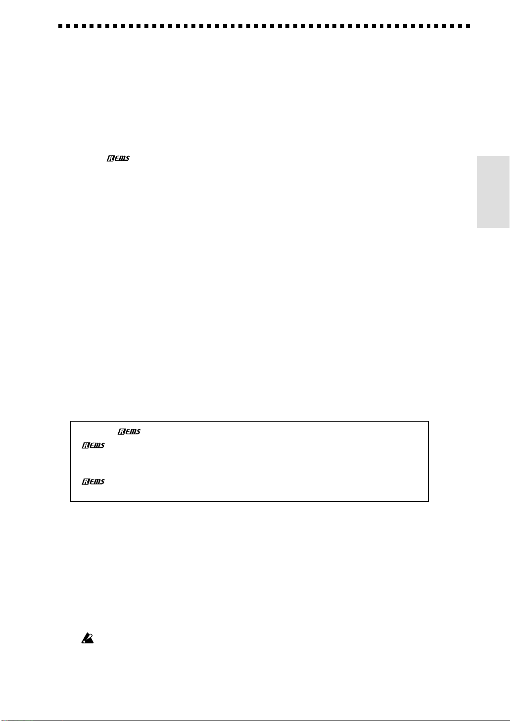
Front and rear panel
Front panel
1 Effect select knobs
These knobs select the effect model used in each effect block.
2 Effect block LEDs
The LED will light for effect blocks that are in use. During editing, the LED of the
selected effect block will blink.
3 Effect block select switches
Press these switches to turn each effect block on/off.
4 Value LEDs
These LEDs will light to indicate the value knobs that can be used for the selected effect
model. From the left, they correspond to value knobs 1—5.
5 Value knobs
When editing, rotate these knobs to modify the value of the parameter assigned to each
knob. From the left, these are value knobs 1—5.
When not editing, these knobs control the parameters of the effect that is assigned to the
DRIVE-AMP effect block by the selected program. (Refer to p.12, “Quick editing for the
DRIVE-AMP effect block.”) In general, this is the most important tone shaping effect in a
multi effect set up.
6 Program LEDs
The LED of the currently selected program number will light.
7 Program switches
Use these switches to select a program.
8 Bank switch
Each time this switch is pressed, the bank number will increase by one. The bank
number will decrease by one if you simultaneously press the bank switch and program
switch 4.
9 Expression pedal
This pedal controls the effect that is selected for the PEDAL effect block.
4
Page 5
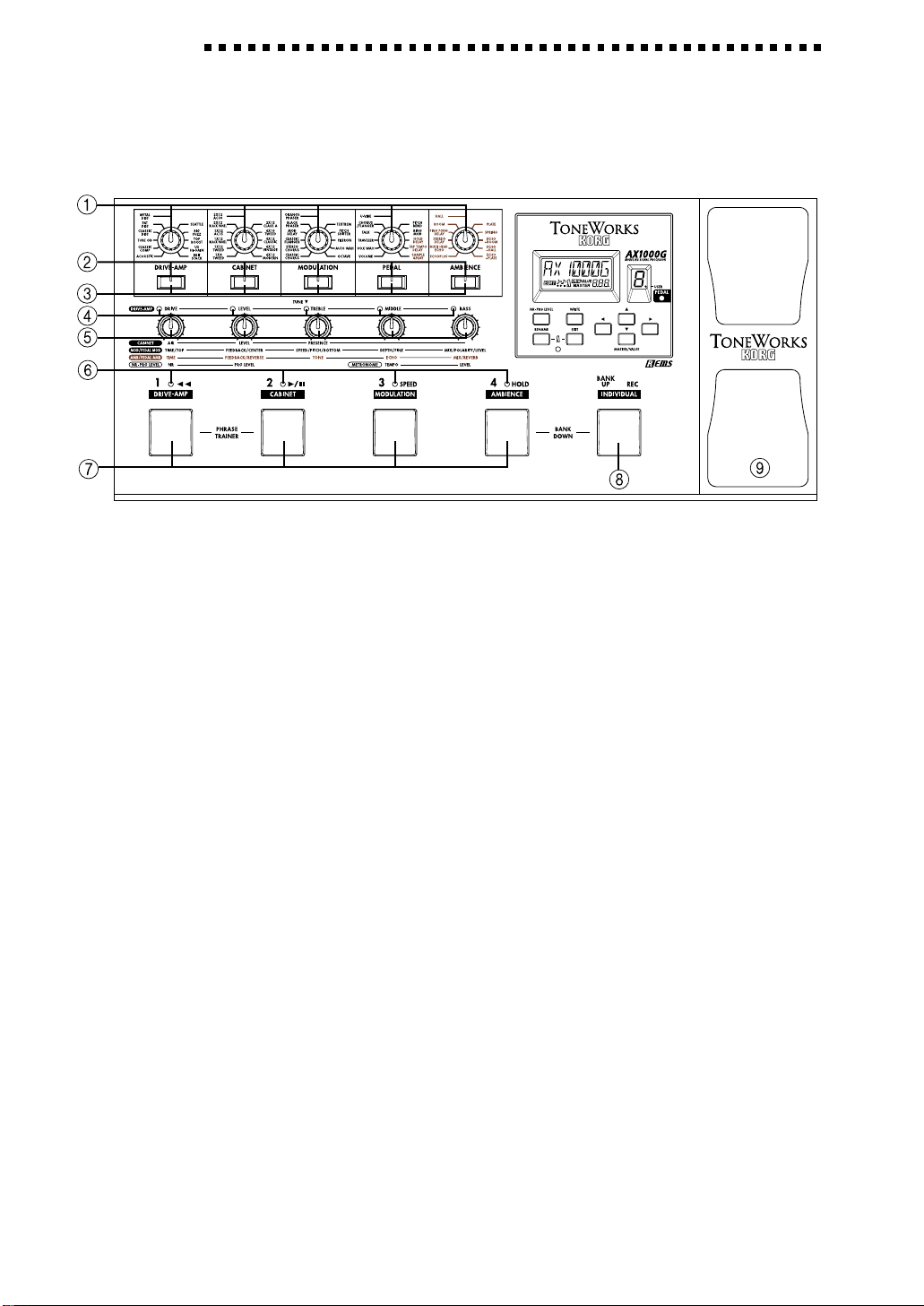
LCD and control panel
1 Name display
This shows the program name, effect
name, or parameter name, as appropri-
ate for each operation.
2 Edit icon
This will light if the selected program has been edited. It will blink if the program is
currently being edited.
3 Phrase trainer icon
This will blink when you are in Phrase Trainer mode.
4 Metronome icon
This will light when the metronome is on. It will blink while the metronome tempo or
level is being adjusted.
5 MASTER/VALUE display
This indicates the master level or parameter values.
6 NR-PRG LEVEL switch
Use this switch to adjust the amount of noise reduction or the level of each program.
7 RENAME switch
Use this switch to modify the name of a program.
8 Metronome LED
This LED will blink in time with the metronome tempo.
9 EXIT switch
From any state, you can press this to return to Play mode.
0 WRITE switch
Use this switch to save an edited program.
A Cursor switches ( , )
Use these switches to select the parameter that you wish to edit, or when modifying the
name of a program.
1. Introduction
B MASTER/VALUE switches (▲, ▼)
Use these switches to modify the master level or the value of a parameter.
C Pedal LED
This LED indicates the on/off status of the PEDAL effect, or the recording status when
the Sample & Play function is being used.
D Bank number display
This shows the bank of the selected program. When a user program is selected, the
decimal point “.” located at the lower right of the bank number will light.
5
Page 6
1. Introduction
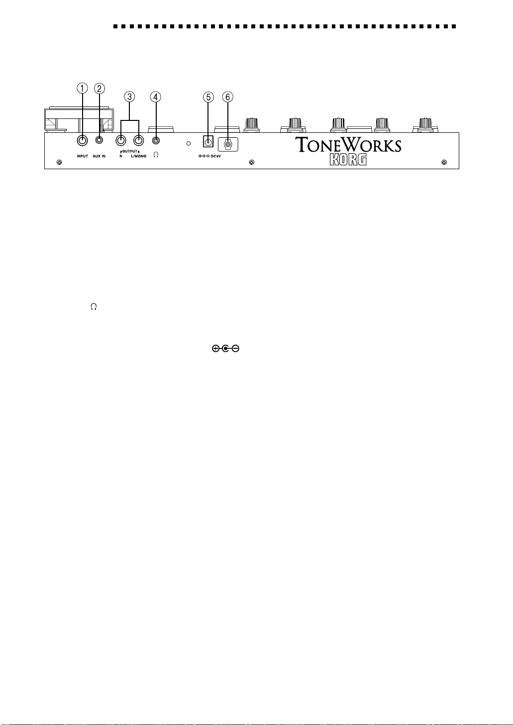
Rear panel
1 INPUT jack
Connect your guitar to this jack.
2 AUX IN jack (stereo mini)
Connect the output (AUX OUT: analog) of your audio device to this jack.
3 OUTPUT jacks (L/MONO, R)
Connect these jacks to your guitar amp or mixer etc. For mono connections, use the L/MONO
jack.
4 : PHONE jack (stereo mini)
Connect a set of headphones to this jack.
5 DC 9V
Connect the included AC adapter ( ) here. When the adapter is connected, the power will
automatically be turned on.
6 Cable hook
Fasten the cable of the AC adapter around this hook. When taking the cable off the hook, avoid
pulling the cable with excessive force.
6
Page 7
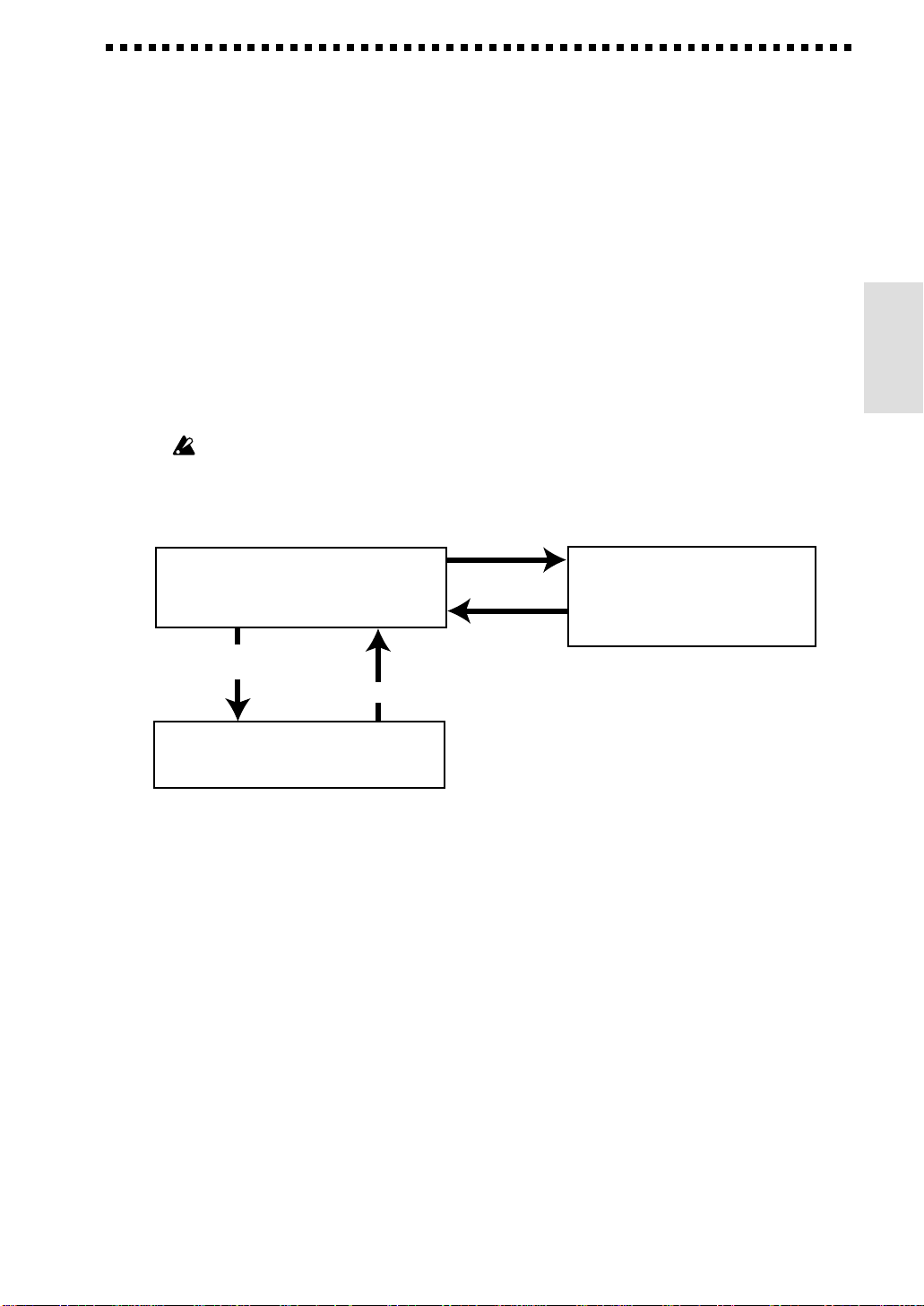
The modes of the AX1000G
The AX1000G has three modes: Play mode, Individual mode, and Phrase Trainer mode.
Play mode is the mode in which you can select a program and play it. You can select from a total
of 80 programs that use high-quality effect models: 40 preset programs, and 40 user programs that
allow you to freely edit the settings to create your very own sounds. When the power is first
turned on, you will always be in this mode.
With the factory settings, the user programs contain the same data as the preset programs.
Individual mode is a mode in which you can use the foot switches (the program switches and
pedal switch) to individually turn each effect block on/off as you play. It is not possible to switch
programs in this mode. Use Play mode to select a programs.
Phrase Trainer mode is a mode in which you can record a phrase from a CD or MD player
connected to the AUX IN jack, and play it back as a loop. You can practice by playing along with
the repeating loop. Since you can fix the pitch and slow down the playback speed, this is conve-
nient for learning or practicing phrases that you have difficulty discerning.
When you enter this mode, the MODULATION, PEDAL, and AMBIENCE effect blocks will
automatically be turned off.
Hold down the bank switch
Play mode
· Select programs (40 preset, 40 user)
· Edit the program
Hold down program switches
1 and 2 together for one second
Press either program
for one second
Individual mode
· Use the program switches to turn
each effect block on/off
Press the
bank switch*
switches 1 and 2 simultaneously
· Edit the program
*
1. Introduction
Phrase Trainer mode
Record and play back a phrase from CD etc.
In Play mode and Individual mode, you can use the effect select knobs etc. to edit the effects,
adjust the noise reduction and program level, and modify the program name etc.
* When you press the EXIT switch
you will always return to Play mode.
7
Page 8

2. Playing the AX1000G
2. Playing the AX1000G
Example connections
The power must be off when you make connections.
Unintentional operation may damage your speaker
system, or cause malfunctions.
1. Connect your cables from the OUTPUT jacks of the
AX1000G to your guitar amp or mixer etc.
If you are using a mono connection, connect the L/
MONO jack. In order to take full advantage of the
AX1000G’s sound, we recommend that you use
stereo connections.
2. If you wish to use headphones, plug them into the
PHONES jack.
The output from the OUTPUT jacks will be turned off
when headphones are plugged in.
3. Connect your guitar to the INPUT jack.
4. If you wish to use the AUX IN jack, connect an
external audio device to it. Use the controls of the
connected device to adjust the volume.
5. Connect the included AC adapter to the DC 9V jack,
and plug the AC adapter into an AC outlet. When
you plug it in, the power will come on automatically, and the name display will indicate the
program name.
Wrap the AC adapter cable around the cable hook. When
removing the cable from the hook, be careful not to pull
the cable with excessive force.
6. When you have finished making connections, turn
on the power of your guitar amp or mixer etc. Play
your guitar to produce sound, and check whether
connections have been made correctly. Adjust the
master level of the AX1000G and the gain or fader
controls of your guitar amp or mixer to set an
appropriate volume level.
Headphones
Guitar amp etc.
Stereo-mini
Included AC adapter
Monaural phone plug
PHONES
DC9V
Audio device
Stereo-mini
AUX IN
OUTPUT
Guitar
mono
INPUT
Play mode
When you turn on the power, the AX1000G will
always enter Play mode, and will be set to the
program and master level setting that were last
selected when the power was turned off.
Adjusting master level
The MASTER/VALUE display will show the master
level immediately after the power is turned on, a
program is selected, and after the EXIT switch is
pressed.
When the master level is shown, you can use the
MASTER/VALUE switches (▲, ▼) to adjust the master
level.
Adjusting input level
By holding down the EXIT switch and pressing the
MASTER/VALUE switches, you will be able to adjust
the input level so that it will match the output of the
connected instrument.
EXIT + ▲ “HI IN”:For high-output pickups such as
humbucking pickups
EXIT + ▼ “LO IN”: For low-output pickups such as
single coil pickups
Selecting a program
You can select from 40 preset programs
and 40 user programs.
User and preset programs are each
organized into ten banks, with four
programs in each bank. The currently
selected bank is shown by the bank
number display, and the program is
shown by the program LEDs. When a
user program is selected, the decimal point “.” located
at the lower right of the bank number display will
light.
To select a program in the same bank
Press a program switch 1—4 to select the desired
program. The program LED of the selected program
will light, and the name display will indicate the
program name.
To select a program from a different bank
Press the bank switch to select the desired bank. (The
bank number display will blink.) The banks will cycle
in the order of user banks 0, 1, 2, 3 ...9, preset banks 0,
1, 2, 3...9, user banks 0, 1, 2, 3...
• Each time you press the bank switch, the bank
number display will increase by one.
• Each time you simultaneously press the bank
switch and program switch 4, the bank number
display will decrease by one.
When the desired bank number appears, press a
program switch 1—4 to select the desired
program.(The bank number display will change from
blinking to lit.)
User
program
Preset
program
8
Page 9

Checking the effect blocks used by a program
Not every program uses all of the effect blocks. When
you select a program, the effect block LED of each
effect block that is used will light. The LEDs of effect
blocks that are unused will be dark.
Bypass and mute
Bypass
If you press and hold the program switch of the
currently selected program for 0.5 seconds, all effects
will be bypassed. At this time, the program LED will
blink, and the name display will indicate “BYPASS”
for one second.
To defeat bypass, press the program switch whose LED
is blinking, or press any other program switch.
Mute
If you press and hold the program switch of the
currently selected program for one second and the
sound of your guitar will be muted. At this time, the
program LED will blink more rapidly, and the name
display will indicate “MUTE” for one second.
To defeat mute, press the program switch whose LED
is blinking, or press any other program switch.
Auto tuner
When the AX1000G is in bypass or mute condition, the
tuner will operate automatically. If you mute the
AX1000G you will be able to tune your instrument
without producing sound. This is used for on stage
tuning.
1. Tune your guitar approximately so that the desired note
name appears in the bank
number display. The decimal
point “.” at the lower right of
the bank number display will
light to indicate a sharp #.
2. Fine-tune your guitar so that only the center of the
five value LED’s is lit (or so that only the center of
the name display is shown).
Tuning discrepancy shown by the value LED’s
and the name display
Value LED’s
Pitch is flat
Pitch is sharp
Correct tuning
Example display
=A
=D
Name display
Changing the calibration setting
As necessary, you can adjust the calibration (the
frequency of the standard A pitch) in the range of
438—445 Hz. (440 Hz is “standard”)
When the tuner is operating, use the MASTER/VALUE
switches (▲, ▼) to adjust the setting. The calibration
setting will appear in the MASTER/VALUE display.
When the power is turned off, the calibration setting you
modify will be lost, and will automatically return to 440 Hz
the next time the power is turned on.
Metronome
1. When you simultaneously press the RENAME and
EXIT switches, the metronome will start. (The
metronome icon will blink.)
2. Use value knob 4 to adjust the tempo (range 40—
208: shown in the MASTER/VALUE display).
3. Use value knob 5 to adjust the volume of the
metronome sound (range 0—30: shown in the
MASTER/VALUE display).
4. While the metronome is operating, simultaneously
press the RENAME and EXIT switches to stop the
metronome.
Tempo
If you switch programs or edit while the metronome is
operating, it will no longer be possible to adjust the
#
tempo or level. To re-adjust the tempo or level, you
must first stop the metronome, and then start it once
again.
When the AX1000G is bypassed or muted, it will not be
possible to adjust the tempo or level.
Level
On, Off
Expression pedal
You can use the expression pedal for realtime control
of eleven types of effects in the pedal effect block.
If the program uses an effect in the pedal effect block,
the pedal effect block LED will light. For the Hold
Delay, Tap Tempo Delay, and Sample & Play pedal
effects, the operation is different than for other effects
(refer to p.21).
2. Playing the AX1000G
9
Page 10

2. Playing the AX1000G
Using the expression pedal as you play
1. In Play mode, select a program that uses the
expression pedal.
2. Make sure that the pedal LED is lit. If it is not lit,
press the expression pedal firmly once to make the
pedal LED light (the pedal will be turned on).
3. Operate the expression pedal while playing your
guitar. As you raise and lower the pedal, the output
sound will change correspondingly.
If Volume is selected in the PEDAL effect block, it will not
be possible to turn the expression pedal on/off. It will
remain on (the pedal LED will be lit).
The on/off status of the expression pedal is not
memorized by each program.
Do not apply excessive force to the expression pedal.
Before operating the expression pedal, verify the amount
of force that is required to make the pedal LED light and
to apply the effect.
Individual mode
In this mode you can press the program switches or
the pedal switch to turn each individual effect block
on/off while you play.
As in Play mode, you can edit the settings, use the
metronome, and write a program.
In this mode it is not possible to switch programs or to
select bypass or mute.
Entering Individual mode
In Play mode press and hold the Bank switch for one
second, and you will enter Individual mode. The name
display will indicate “-INDIV-,” and the bank number
display will indicate “ .”
When you enter Individual mode, the program LED’s
will indicate the on/off status of each effect block
(synchronized with the effect block LED’s).
DRIVE-AMP corresponds to program switch (LED) 1,
CABINET to 2, MODULATION to 3, AMBIENCE to
4, and PEDAL to the expression pedal (pedal LED).
Each time you press a program switch, it will cycle on
or off. For the pedal effect, pressing the expression
pedal firmly will turn it on/off (the switch is located
under the pedal). However for some pedal effects such
as SAMPLE & PLAY, the expression pedal is used in a
special way, and cannot be turned off once the pedal
has been turned on.
For some effects, it is not possible to simultaneously use
the MODULATION and PEDAL effect blocks, or the
PEDAL and AMBIENCE effect blocks. If you attempt to
simultaneously turn on both of these effect blocks in such
a combination, the effect block that was turned on first
will automatically be turned off.
10
Indication of currently used effect blocks
Exiting Individual mode
To return to Play mode, press either the bank switch or
the EXIT switch.
Page 11

Phrase Trainer mode
In this mode, you can record a phrase from an audio
device (CD or MD) connected to the AUX IN jack, and
play it back repeatedly as a loop. Then you can practice
a phrase on your guitar while listening to the repeating
phrase.
Since you can slow down the playback speed without
affecting the pitch, this is a convenient way to learn or
practice phrases from recordings that are difficult to play.
When you enter this mode, the MODULATION, PEDAL,
and AMBIENCE effect blocks will automatically be turned
off. (When you exit Phrase Trainer mode, the previous
settings will be restored.)
1. Enter Phrase Trainer mode
From Play mode, simultaneously press and hold
program switches 1 and 2 for one second. The
MASTER/VALUE display will indicate the selected
recording mode, and the Phrase Trainer icon will blink.
2. Select the recording mode
Use the MASTER/VALUE switches (▲, ▼) to select the
recording mode. When the name display indicates
“SHT,” a maximum of 8 seconds can be recorded (high
quality sound). When it indicates “LNG”, a maximum
of 16 seconds can be recorded (extended recording
time). The phrase will be recorded and played back
monaurally.
3. Begin recording
Start the audio device that is connected to the AX1000G,
and press the bank switch (REC) at the point where you
wish to begin recording. The name display will indicate
“REC” and the number of seconds of recording.
Once you record a phrase, it is not possible to change
the recording mode. If you wish to change the recording
mode, you must return to Play mode, and once again
enter Phrase Trainer mode.
4. Stop recording
At the point where you wish to stop recording, press
program switch 2 ( )or the bank switch (REC).
Recording will end, and the name display will indicate
“PLAY.” The recorded phrase will automatically begin
playing repeatedly as a loop.Recording will also end
automatically if you continue recording for the
maximum time length of the selected recording mode.
Depending on the volume of the connected audio device,
the sound may be distorted. If this occurs, adjust the
volume on the audio device.
The sound of your guitar will be muted during recording.
To re-do the recording
Press program switch 2 ( ) to stop playback. Then
continue with step “3. Begin recording” and step “4.
Stop recording.”
To erase the recorded phrase
Press the EXIT button to delete the phrase. Alternatively, you can record a new phrase to overwrite the
previously-recorded phrase.
5. Stop
When you press program switch 2 ( ), playback
will stop. Press program switch 2 ( ) once again,
and playback will resume from where you stopped.
·
If program switch 1 ( ) is pressed while stopped,
you will return to the beginning of the recorded phrase.
· By pressing the cursor switches, you can playback in
reverse ( ) or forward ( ) as long as you hold down
the switch.
· During recording or while stopped, the sound that is
connected to the AUX input will be heard.
· When not recording, you can use the expression
pedal to adjust the level of the effect sound.
6. Playback
During recording or while stopped, press program
switch 2 ( )
repeating loop.
By pressing program switch 3 (SPEED) or the MAS-
TER/VALUE switches (▲, ▼), you can slow down the
playback speed without affecting the pitch.
· Each time you press program switch 3 (SPEED), the
playback speed will cycle through settings of 100%,
75%, 50%, 25%, 100% ...
· By pressing the MASTER/VALUE switches (▲, ▼), the
speed can be adjusted in 5% steps; 100%, 95%, 90%, ... 25%
During playback, you can press cursor switch ( ) to
playback at double speed as long as you continue
pressing the switch.
If you press cursor switch ( ), the recording will play back
in reverse as long as you continue pressing the switch.
If you press program switch 1 ( ), the recording will
rewind as long as you continue pressing the switch.
to playback the recorded phrase as a
7. Hold
By pressing program switch 4 (HOLD), you can hold the
sound that was playing at the moment the switch was
pressed. When you press the switch once again, hold
will be defeated. By pressing a cursor switch while the
sound is being held, you can playback backward ( ) or
forward ( ) as long as you continue holding the switch.
If you press program switch 1 ( ), you will go back
one second, cancel Hold, and begin playback.
Rewind/Cue
Start/stop playback
Change playback speed
Hold
Start/stop recording
Exiting Phrase Trainer mode
To return to Play mode, you can either press program
switches 1 and 2 simultaneously, or press the EXIT switch.
When you exit Phrase Trainer mode or turn off the power,
the recorded phrase will be erased.
.
2. Playing the AX1000G
11
Page 12
3. Editing
3. Editing
In Play mode and Individual mode, you can edit each
effect, set noise reduction and program level, and
modify the program name.
In Phrase Trainer mode, it is possible to edit the DRIVEAMP and CABINET effect blocks, but it is not possible to
perform editing operations that use the name display or
MASTER/VALUE display, or the cursor switches or the
MASTER/VALUE switches.
During editing, the edit icon in the display will blink.
The parameter assigned
to the knob you moved
Edit icon
Editing effects
Rotate the effect select knob of the effect block that you
wish to edit, or press the corresponding effect block
select switch. The effect block LED will begin blinking,
indicating that it has been selected for editing.
Use the effect select knob, effect block select switch,
and value knobs to edit the settings.
If you wish to save the edited effect, perform the
“Program write” operation. If you fail to do this, the effect
program will revert to its original settings when you turn
off the power or select a different program.
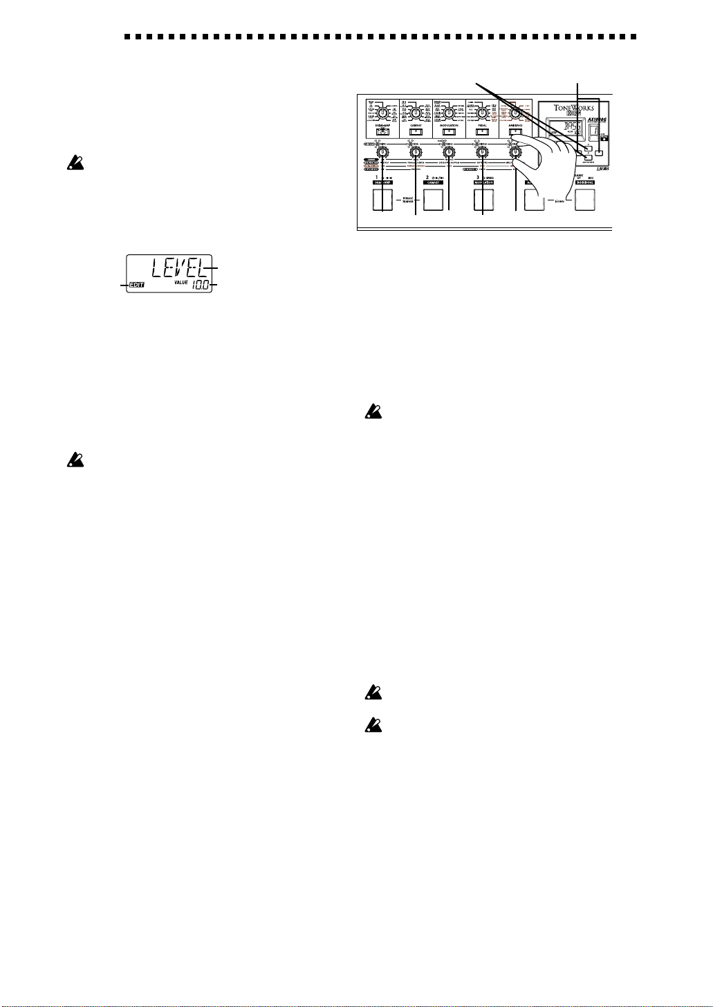
As an example, we will explain how to edit the TUBE
OD (Tube Overdrive) effect of the DRIVE-AMP block.
1. If the name display indicated “TUBE OD” when
you pressed the effect block select switch, simply
continue. If not, turn the DRIVE-AMP effect select
knob to the TUBE OD position. If the effect select
knob was already located at TUBE OD, first select a
different effect model, and then turn the knob back
to TUBE OD.
2. The effect block LED will begin blinking, indicating
that it has been selected for editing. (The name
display will indicate the model name as “TUBE
OD.”) If you selected a programmed effect, the
ORIG icon will light.
3. The five value LED’s will light, and the corresponding value knobs will be assigned to DRIVE,
LEVEL, TREBLE, MIDDLE, and BASS respectively, and will function as knobs that adjust the
value of each parameter. (Refer to p.16, “Effect
parameters.”)
4. Rotate the knobs and the sound will change. The
name display will indicate the name of the
parameter assigned to that knob, and the MASTER/VALUE display will indicate the value. At this
time, the ORIG icon will light when the position of
the knob matches the original value — i.e., the
value before you began editing.
Value of the parameter
Modifying a parameter value
LEVEL
TREBLE
DRIVE
MIDDLE
Selecting a parameter
BASS
Instead of the five value knobs, you can also use the
cursor switches to select parameters, and use the
MASTER/VALUE switches (▲, ▼) to adjust the value
of the parameter currently shown in the name display.
If you do not wish to use the DRIVE-AMP effect block,
press the DRIVE-AMP effect block select switch until
the LED goes dark. The DRIVE-AMP effect block is
now bypassed, and the name display will indicate “OFF-.”
For some effects, it is not possible to simultaneously use
the MODULATION and PEDAL effect blocks, or the
PEDAL and AMBIENCE effect blocks. If you attempt to
turn on both effect blocks in such a combination, the
block that had been turned on will automatically be
turned off.
Quick Editing for the DRIVE-AMP effect block
In the default state of each mode, the DRIVE-AMP
effect block parameters used by the selected program
are assigned to the value knobs (except when the effect
is off).
By rotating the respective value knobs, you will enter
Edit mode (the effect block LED will blink); the name
display will indicate the parameter name, the MASTER/VALUE display will show the value, and the
sound will change.
If you wish to change an effect that is in use, use the
effect select knobs to select the desired effect.
It is not possible to edit when other functions are
assigned to the value knobs, when the AX1000G is
bypassed, muted, or recording in Phrase Trainer mode.
12
Page 13

Setting the noise reduction and program levels
1. If you are in Play mode, press the NR-LEVEL
switch.
2. By rotating value knobs 1 or 2, or pressing the NRLEVEL switch, you can access the screen displays
for adjusting the noise reduction and setting the
level for each program.
3. To adjust the amount of noise reduction, use value
knob 1 (range OFF...10: shown in the MASTER/
VALUE display).
4. To adjust the level of each program, use value knob
2 (range 0...10: shown in the MASTER/VALUE
display).
5. When you finish making settings, press the EXIT
switch to return to Play mode.
Noise reduction
Instead of value knobs 1 and 2, you can also use the
cursor switches to select a parameter and use the
MASTER/VALUE switches (▲,▼) to adjust the value
of the parameter.
It is not possible to turn noise reduction off.
Depending on the guitar that you use, raising the noise
reduction setting too high may cause the sound to be cut
off at low levels.
The volume of each program will change depending on
the guitar that you use. Adjust the program level for your
guitar.
If you wish to save the noise reduction and program level
settings that you edited, you must perform the “Program
write” operation. If you turn off the power or select a
different program without writing the program, the
program you modified will revert to its previous settings.
Level
Modifying program names
Press the RENAME switch and specify the desired
program name. Use the cursor switches ( , ) to
select the character that you wish to change (the
character will blink). Then use value knob 5 (or the
MASTER/VALUE switches) to select the desired
character. The available characters are shown below.
Available characters
Select characters
If you wish to save the modified program name, you must
perform the “Program write” operation. If you turn off the
power or select a different program without writing the
program, the program name you edited will revert to its
previous setting.
Move between
character positions
Writing programs
Here’s how to write an edited program.
1. Press the WRITE switch, and the name display will
indicate “✳WRITE✳.” The bank number display
and the program LED will blink.
2. Use the MASTER/VALUE switches (or value knob
5 and the bank switch) to select the writing
destination bank, and use the cursor switches (or
the program switch) to select the writing destination program.
3. Press the WRITE switch once again, and the display
will read “COMPLT” to indicate that the program
has been written. You will then return to Play
mode.
If you decide not to write, press the EXIT switch to
cancel the Write operation.
Select the bank Select the program
3. Editing
Select the bankSelect the program
If you write an edited program to a different program
number, the program that was overwritten will be lost.
It is not possible to write to a preset program.
13
Page 14

4. Appendices
4. Appendices
Adjusting the expression pedal
(Calibration)
If you find the expression pedal difficult to use,
perform this procedure so that the pedal will function
optimally. For example if the effect does not reach
maximum when the pedal is advanced all the way, or
does not reach minimum when the pedal is returned
all the way, use the following procedure to make the
appropriate adjustments.
When making adjustments, use your hand to move the
pedal. Accurate calibration may not be possible if you use
your foot to operate the pedal.
1. Turn on the power while simultaneously holding
down the EXIT switch and the PEDAL effect block
select switch.The name display will show “PEDAL”
for approximately one second, and will then
indicate “MIN.”
2. Slowly return the pedal to the full back position.
When it stops, release your hand and press the
WRITE key.The name display will change from
“MIN” to “MAX.”
If you decide to halt the adjustment procedure, press the
EXIT switch. The power-on display will appear, and you
will enter Play mode.
3. Slowly advance the pedal. When it stops, release
your hand and press the WRITE key.
Restoring the user programs to
the factory settings (Reload)
1. Turn on the power while simultaneously holding
down the EXIT switch and the bank switch. The
name display will indicate “RELOAD?”
If you press the EXIT switch, the reload operation will not
occur; the power-on display will appear, and you will
enter Play mode.
2. Press the WRITE switch. The name display will
change to “RELOAD,” and the reload operation
will begin. When the reload operation is completed,
the display will indicate “COMPLT” for approximately one second. Then the power-on display will
appear, and you will enter Play mode.
Never turn off the power during the reload operation.
When you perform the reload operation, all user
programs will be rewritten. Master level, metronome, and
input level settings will also be initialized.
2. Press slowly
The LCD display will indicate “COMPLT” for
approximately one second. Then the power-on display
will appear, and you will enter Play mode.
After the adjustment procedure has been completed,
verify the operation of the pedal.
Select an effect that will make it easy to verify the
adjustment. For example, set the pedal effect block to
the VOLUME effect, set the value to 0, and check the
MIN level when the pedal is returned all the way.
If you make a mistake during the calibration procedure,
the LCD will indicate “ERROR,” and you will return to the
screen before the adjustment (the “MIN” display). If the
“ERROR” display appears for repeated attempts, a
malfunction may have occurred. In this case, please
contact your dealer.
3. Press slowly
14
Page 15

Troubleshooting
If you suspect a malfunction, please check the
following points first. If this does not resolve the
problem, contact a nearby dealer.
1. Power does not turn on
· Is the AC adapter plugged into an AC outlet?
(☞p.6, 8)
· Is the included AC adapter connected? (☞p.6, 8)
2. No sound
· Are your guitar, amp, and headphones respectively
connected to the correct jack? (☞p.6, 8)
· Is the power of your amp turned on, and is it set
accordingly?
· Is one of your connection cables broken?
· Is the master level of the AX1000G set to “0” or to a
low value? (☞p.8)
· Is the program level of the AX1000G set to “0” or to
a low value? (☞p.13)
· Is the LEVEL of the DRIVE-AMP effect set to “0”
or to a low value?
· Is the volume of your guitar turned down?
· Is the AX1000G muted?
· If VOLUME is selected for the PEDAL effect, has
the pedal been returned to the full back position?
Main specifications
• Number of effects: 56 types (maximum number of
effects usable simultaneously: 8)
• Number of programs: 80 (40 preset, 40 user)
• Inputs: Guitar input (mono phone jack)
AUX IN (stereo mini jack)
• Outputs: Output x 2 (mono phone jack)
Headphones (stereo mini jack)
• Tuner section
Detection range: 27.5 Hz — 2,093 Hz (A0—C7)
Calibration: A=438—445 Hz
• Metronome section
Tempo: bpm= 40—208
• Power supply:
• Dimensions: 420 (W) x 187.7 (D) x 65.4 (H) mm
• Weight: 2.4kg
• Included items: Owner’s manual
* Specifications and appearance are subject to change
with out notice for improvement.
DC9V (included AC adapter )
AC adapter
3. Effects are not applied
· Is the AX1000G bypassed? (☞p.9)
· Are the effects used by the program turned on?
(☞p.4, 9)
4. Metronome does not function
· Are you in Play mode or in Individual mode?
The metronome will not function in Phrase Trainer
mode.
· Is the metronome output level set to “0”? (☞p.9)
5. Pedal does not function
· Have you selected a program that uses an effect in
the PEDAL effect block? (☞p.9)
· Is the pedal LED lit? (☞p.9)
· Try adjusting (calibrating) the expression pedal.
(☞p.14)
6. Cannot write (the name display indicates “ER-
ROR”)
· Reload the preset programs. (☞p.14)
4. Appendices
15
Page 16

4. Appendices
Effect parameters
DRIVE-AMP effects block
These effect models consist of effects plus a three-band
equalizer.
DRIVE-AMP
Knob 1 Knob 2 Knob 3 Knob 4 Knob 5
DRIVE LEVEL TREBLE MIDDLE BASS
ACOUSTIC 1...10 0...10 0...10 0...10 0...10
CLASSIC COMP 1...10 0...10 0...10 0...10 0...10
TUBE OD 1...10 0...10 0...10 0...10 0...10
CLASSIC DIST 1...10 0...10 0...10 0...10 0...10
FAT DIST 1...10 0...10 0...10 0...10 0...10
METAL DIST 1...10 0...10 0...10 0...10 0...10
SEATTLE 1...10 0...10 0...10 0...10 0...10
BIG FUZZ 1...10 0...10 0...10 0...10 0...10
TOP BOOST 1...10 0...10 0...10 0...10 0...10
US HI-GAIN 1...10 0...10 0...10 0...10 0...10
BRIT STACK 1...10 0...10 0...10 0...10 0...10
Acoustic simulator
This is an effect model that converts the sound of an electric
guitar to that of an acoustic guitar.
ACOUSTIC “ACOUSTIC”
A more realistic simulation of an acoustic guitar will be
produced if you use the neck pickup.
A compressor with adjustable sensitivity is built-in.
If the sound distorts, slightly decrease the LEVEL,
TREBLE, MIDDLE, and BASS.
Knob 1 DRIVE Adjusts the compressor sensitivity.
Knob 2 LEVEL Adjusts output level.
Knob 3 TREBLE Adjusts treble (high-frequency range).
Knob 4 MIDDLE Adjusts mid (mid-frequency range).
Knob 5 BASS Adjusts bass (low-frequency range).
Compressor
A compressor boosts quiet sounds and decreases loud sounds to
even out differences in volume, in order to make the dynamics
more consistent.
CLASSIC COMP “CL COMP”
This is a compressor makes your playing dynamics more
consistent, and produces a smooth sustain. This model is based
on a combination of two popular vintage compressors.
If the sound distorts, slightly decrease the LEVEL,
TREBLE, MIDDLE, and BASS.
Knob 1 DRIVE Adjusts sensitivity.
Knob 2 LEVEL Adjusts output level.
Knob 3 TREBLE Adjusts treble (high-frequency range).
Knob 4 MIDDLE Adjusts mid (mid-frequency range).
Knob 5 BASS Adjusts bass (low-frequency range).
Overdrive, Distortion, Fuzz, Amp
The effect model offers a wide variety of classic sounds.
TUBE OD “TUBE OD”
This model simulates the overdriven sound of a popular tube
overdrive pedal from the 70’s that responds well to the
nuances of your picking.
CLASSIC DIST “CL DIST”
This model simulates a poular distortion pedal from the 70’s.
FAT DIST “FATDIST”
This model simulates a popular fat sounding disortion pedal
from the 80’s.
METAL DIST “MTLDIST”
This model simulates the metallic distortion of the 90’s.
SEATTLE “SEATTLE”
This model is ideal for grunge rock sounds.
BIG FUZZ “BIGFUZZ”
Big sound and a big figure -- the definitive fuzz.
TOP BOOST “TOP BST”
This model simulates the sound of an AC30 overdriven by a
popular 80’s OD pedal.
US HI-GAIN “US HI-G”
This model simulates the distortion typical of a high-gain amp
made in the USA.
BRIT STACK “BRTSTK”
This model simulates the distortion typical of a British amp
stack.
Knob 1 DRIVE Adjusts amount of distortion.
Knob 2 LEVEL Adjusts output level.
Knob 3 TREBLE Adjusts treble (high-frequency range).
Knob 4 MIDDLE Adjusts mid (mid-frequency range).
Knob 5 BASS Adjusts bass (low-frequency range).
16
Page 17

CABINET effect block
The shape of the cabinet and the type and number of speakers
are very important elements in determining the tonal character
of a guitar amp.
The CABINET effect block provides models that faithfully
simulate the cabinet and speaker characteristics of a variety of
guitar amps, from vintage to modern.
Although these models are especially effective when you are
plugged in to a mixer etc. via a direct line connection, they are
also effective when you are using a guitar amp.
CABINET
Knob 1 Knob 2 Knob 3 Knob 4 Knob 5
AIR LEVEL PRESENCE
1x8 TWEED AP, 0.3...9.7, Ln 1...10 0...10
1x12 TWEED AP, 0.3...9.7, Ln 1...10 0...10
1x12 BLACK PANEL AP, 0.3...9.7, Ln 1...10 0...10
1x12 AC15 AP, 0.3...9.7, Ln 1...10 0...10
2x12 BLACK PANEL AP, 0.3...9.7, Ln 1...10 0...10
2x12 AC30 AP, 0.3...9.7, Ln 1...10 0...10
2x12 CLASS A AP, 0.3...9.7, Ln 1...10 0...10
4x10 TWEED AP, 0.3...9.7, Ln 1...10 0...10
4x12 CLASSIC AP, 0.3...9.7, Ln 1...10 0...10
4x12 VINTAGE AP, 0.3...9.7, Ln 1...10 0...10
4x12 MODERN AP, 0.3...9.7, Ln 1...10 0...10
1x8 TWEED “1–8 TWD”
This model simulates an open back cabinet with one 8-inch
speaker.
1x12 TWEED “1-12 TWD”
This model simulates an open back cabinet with one 12-inch
speaker typically used for blues.
1x12 BLACK PANEL “1-12 BLK”
This model simulates an American open back cabinet with one
12-inch speaker and a bright tonal character.
1x12 AC15 “1-12AC15”
This model simulates a Vox open back cabinet with one 12-inch
“Blue” speaker.
2x12 BLACK PANEL “2-12 BLK”
This model simulates an American open back cabinet with two
12-inch speakers.
2x12 AC30 “2-12AC30”
This model simulates a Vox open back cabinet with two 12inch “Blue” speakers.
2x12 CLASS A “2-12 CLA”
This model simulates a modern open back cabinet with two 12inch speakers.
4x10 TWEED “4-10 TWD”
This simulates an open back cabinet with four 10-inch
speakers.
4x12 CLASSIC “4-12 CLS”
This simulates a closed back cabinet with four 25W 12-inch
speakers.
4x12 VINTAGE “4-12 VIN”
This simulates a closed back cabinet with four 30W 12-inch
speakers.
4x12 MODERN “4-12 MDN”
This simulates a closed back cabinet with four 75W 12-inch
speakers.
Knob 1 AIR This simulates the resonance of the
cabinet, and the comb filtering effect
produced by interference between the
speakers.
Decreasing this value will produce a
sound that is more suitable for connection
to a guitar amp. Increasing this value will
produce a sound that is more suitable for
direct-line connection.
Knob 2 LEVEL Adjusts output level.
Knob 3
PRESENCE
If the sound distorts, slightly lower the LEVEL and
PRESENCE.
Adjusts tone of the high-frequency range.
4. Appendices
17
Page 18

4. Appendices
MODULATION effect block
MODULATION
Knob 1 Knob 2 Knob 3 Knob 4 Knob 5
TIME FEEDBACK SPEED/PITCH DEPTH/FINE
MIX/POLARITY
CLASSIC CHORUS 0.1...10[Hz] 0...10 1, 2
STEREO CHORUS 1...10 0.1...10[Hz] 0...10
CLASSIC FLANGER 1...10 0...10 0.1...10[Hz] 0...10
MOD DELAY 0.5...900[ms] 0...10 0.1...10[Hz] 0...10 0...10
BLACK PHASER 0...10 0.1...10[Hz]
ORANGE PHASER 0...10 0.1...10[Hz]
TEXTREM 1...10[Hz] 0...10
PITCH SHIFTER 0...900[ms] 0...10 –24...24[x100 CENT] –15...15[CENT] 0...10
FILTRON 1...10 0...10 0...10 up, dn
AUTO WA H 1...10 0...10 up, dn
OCTAVE 0...10 0...10
Chorus, Flanger
Chorus and flanger are effects that delay the sound slightly to
modulate the pitch, and combine the modulated sound with the
original to produce a sensation of modulated spaciousness.
CLASSIC CHORUS “CL CHOR”
This simulates the very first vintage chorus unit. For the best
results, use it in stereo .
Knob 3 SPEED Adjusts speed.
Knob 4 DEPTH Adjusts depth.
Knob 5 MIX 1: Use for mono output.
2: Use for stereo output.
STEREO CHORUS “ST CHOR”
This simulates a vintage stereo chorus unit that inverts the
phase of the effect sound between left and right channels to
make the sound more spacious. Adjusting the three knobs can
produce a wide variety of results.
Knob 1 TIME Adjusts delay time.
Knob 2 ——— ————
Knob 3 SPEED Adjusts speed.
Knob 4 DEPTH Adjusts depth. If this knob is placed in the
“10” position, the TIME knob will have no
effect.
MOD DELAY “MOD DLY”
This effect modulates the delay time to produce chorus and
flanger-like effects. Adding a small amount of depth with
longer delay settings gives you a very effective modulated
echo sound.
Knob 1 TIME Adjusts delay time.
Knob 2
FEEDBACK
Knob 3 SPEED Adjusts speed.
Knob 4 DEPTH Adjusts depth.
Knob 5 MIX Adjust the mix amount of effect sound.
Adjusts feedback.
Phaser
This effect cyclically modifies the phase shift of the sound, and
mixes the phase-shifted sound with the original sound to
produce modulation. The phased sound will become milder as
the number of stages is increased.
BLACK PHASER “BL PHAS”
This is a popular four-stage vintage phaser.
ORANGE PHASER “OR PHAS”
This is a ten-stage vintage phaser that produces a milder
effect.
Knob 2
FEEDBACK
Knob 3 SPEED Adjust the speed of modulation.
Adjust the degree of character.
CLASSIC FLANGER “CL FLAN”
This is a vintage flanger with rich tone. The settings can also be
adjusted to produce chorus or vibrato-like effects.
Knob 1 TIME Adjust the delay time. This controls the
bandwidth over which the effect is applied.
As this setting approaches 0, modulation
will occur at a higher pitch.
Knob 2
FEEDBACK
Knob 3 SPEED Adjusts speed.
Knob 4 DEPTH Adjusts depth. If this knob is placed in the
Adjust the strength of tonal character. To
produce a jet airplane-like sound, increase
to desired level.
“10” position, the TIME knob will have no
effect.
18
Tremolo
This modulates the volume to add depth to the sound.
TEXTREM “TEXTREM”
This effect model simulates the tremolo built into a guitar
amp.
Knob 3 SPEED Adjusts speed.
Knob 4 DEPTH Adjusts depth.
Page 19

Pitch shifter
This effect modifies the pitch.
PITCH SHIFTER “PITCH”
This pitch shifter can be adjusted over a +/-2 octave range.
Knob 1 TIME Adjusts delay time.
FEEDBACK
Knob 2
Knob 3 PITCH Adjusts amount of pitch change.
Knob 4 FINE Fine adjustment for the amount of pitch
Knob 5 MIX Adjusts mix amount of effect sound.
Adjusts amount of feedback
(delay repeats).
change.
Auto wah
This is an auto-wah filter that automatically opens and closes
according to the attack with which you play your guitar. The
effect will vary depending on the guitars volume setting.
FILTRON “FILTRON”
This is a low-pass filter type auto-wah.
Knob 1 TIME Adjust the speed at which the wah will
rise in response to your picking.
Knob 2
FEEDBACK
Knob 3 ——— ————
Knob 4 DEPTH Adjust the sensitivity with which the wah
Knob 5 POLARITY Specify the direction in which the wah will
Adjust the peak of the wah sound.
will respond to your picking.
operate.
AUTO WAH “AUTOWAH”
This is a band-pass filter type auto-wah that is equivalent to a
pedal wah. It is placed before the DRIVE-AMP effect block.
Knob 1 TIME Adjust the speed at which the wah will
rise in response to your picking.
Knob 2 ——— ————
Knob 3 ——— ————
Knob 4 DEPTH Adjust the sensitivity with which the wah
will respond to your picking.
Knob 5
POLARITY
Specify the direction in which the wah will
operate.
Octave
This generates a pitch one octave lower than the original sound,
and mixes it with the original sound to add a sense of depth and
low end.
This effect may not operate correctly if two or more
strings are played simultaneously, or when low-pitched
strings are played.
OCTAVE “OCTAVE”
Knob 4 DEPTH Adjust the amount of the ultra-low pitch
(one octave below).
Knob 5 MIX Adjust the amount of the original sound.
4. Appendices
19
Page 20

4. Appendices
PEDAL effect block
These effect models let you use the expression pedal to control
the effect in realtime. They include a volume pedal, modulationtype effects such as VOX WAH—RING MOD, and ambience-
type effects such as HOLD DELAY—SAMPLE&PLAY.
VOX W AH—RING MOD cannot be used simultaneously
with the MODULATION effect block. Nor is it possible to
use HOLD DELAY—SAMPLE&PLAY simultaneously with
the AMBIENCE effect block.
PEDAL
VOLUME 0...10
VOX WAH
TRAVELER 0...10 0...10
TALK A, E, I, O, U A, E, I, O, U A, E, I, O, U
CHORUS/FLANGER 1...10 0...10 0.1...10 0...10
U-VIBE 0...10 1, 2
PITCH BEND 0...900[ms] 0...10 –24...24[x100
RING MOD 1...10
HOLD DELAY 0[ms]...3[SEC] 0...10 1...10 0...10
TAP DELAY 0[ms]...3[SEC] 0...10 1...10 0...10
SAMPLE&PLAY 0.5...8[SEC] OFF, 1, 2...8, LP1, LP2 0...10
Knob 1 Knob 2 Knob 3 Knob 4 Knob 5
FEEDBACK/ BOTTOM/SPEED/ LEVEL/MIX/
TOP/TIME CENTER/REVERSE PITCH/TONE DEPTH/FINE POLARITY
CENT
] –15...15[
CENT
] 0...10
Volume
This is a volume pedal.
VOLUME “VOLUME”
Knob 5 LEVEL Adjust the minimum level for when the
pedal is in the full back position.
Pedal wah, Traveler, Talking pedal
These are wah (filter) effects that use the pedal to control the
frequency response.
If you use this effect in a program where the MODULATION effect block is turned on, the MODULATION effect
block will automatically be turned off.
VOX WAH “WAH”
This simulates a vintage wah pedal. There are no adjustable
parameters. It is placed ahead of the DRIVE-AMP effect block.
TRAVELER “TRAVEL”
This is a low-pass filter type wah modeled after a vintage Korg
effect pedal.
Knob 1 ——— ————
Knob 2
FEEDBACK
Knob 3 ——— ————
Knob 4 ——— ————
Knob 5 LEVEL Adjust the output level.
TALK “TALK”
This adds vocal type effects to your guitar.
Knob 1 TOP Select the vowel sound produced when
Knob 2 CENTER Select the vowel sound produced when
Knob 3 BOTTOM Select the vowel sound produced when
* Vow el sounds — A, E, I, O, U
Adjust the peak amount of the filter.
the pedal is fully advanced.
the pedal is in the halfway position.
the pedal is fully raised.
Chorus/Flanger
This is a chorus/flanger effect that uses the pedal to control the
mix amount of the effect.
If you use this effect in a program where the MODULATION effect block is on, the MODULATION effect block
will automatically be turned off.
CHORUS/FLANGER “CH/FLAN”
Knob 1 TIME Adjusts delay time.
Knob 2
FEEDBACK
Knob 3 SPEED Adjusts pitch modulation speed.
Knob 4 DEPTH Adjusts pitch modulation depth.
Adjusts amount of feedback
(delay repeats).
U-Vibe
This simulates a vintage vibrato/rotary speaker simulator.
If you use this effect in a program where the MODULATION effect block is on, the MODULATION effect block
will automatically be turned off.
U-VIBE “U-VIBE”
Knob 4 DEPTH Adjusts depth of the effect.
Knob 5 MODE 0: Mixes the original sound with the ef-
fected sound (Chorus mode)
1:Output only the effect sound
(Vibrato mode)
20
Page 21
Pitch bend
This is a Pitch shifter that uses the pedal to control the pitch.
If you use this effect in a program where the MODULATION effect block is on, the MODULATION effect block
will automatically be turned off.
PITCH BEND “P BEND”
Knob 1 TIME Adjust the delay time.
Knob 2
FEEDBACK
Knob 3 PITCH Adjust the amount of pitch change.
Knob 4 FINE Make fine adjustments to the amount of
Knob 5 MIX Adjust the mix amount of the effect. With
Adjust the amount of feedback
(delay repeats).
pitch change.
a setting of 10, only the effect sound will
be output.
Ring modulator
This effect multiplies the original sound with a sine wave to
produce bell-like effects. The cleanest results will be produced if
you use the neck pickup of your guitar, turn down the tone, and
pluck the string near the twelfth fret.
If you use this effect in a program where the MODULATION effect block is on, the MODULATION effect block
will automatically be turned off.
RING MOD “RINGMOD”
This is a ring modulator that lets you use the pedal to control
the frequency.
Knob 3 PITCH Adjust the tone when the pedal is
advanced.
Delay
These effects mix a time-delayed sound with the original sound
to add depth and spaciousness to the sound.
If you use this effect in a program where the AMBIENCE
effect block is on, the AMBIENCE effect block will
automatically be turned off.
HOLD DELAY “HOLDDLY”
This will normally function as a delay, but when the pedal is
advanced all the way forward to press the switch, the pedal
LED will light and the sound will be held (the delay sound will
continue to be heard). Since you can use the pedal to control
the input level to the delay, you can easily produce special
effects such as sound-on-sound.
TAP DELAY “TAP DLY”
This is a tap tempo delay that allows you to set the delay
tempo by pressing the pedal switch twice. While the tempo is
being specified, the pedal LED will light.
Knob 1 TIME Adjust the delay time.
Knob 2
FEEDBACK
Knob 3 TONE Adjust the tone of the effect sound.
Knob 4 ——— ————
Knob 5 MIX Adjust the mix amount of the effect
Adjust the feedback amount
(delay repeats).
sound.
Sample and play
If you use this effect in a program where the AMBIENCE
effect block is on, the AMBIENCE effect block will
automatically be turned off.
SAMPLE&PLAY “S+PLAY”
This allows approximately 8 seconds of recording. By using the
reverse setting, you can produce special “scratch” effects.
1. Press the expression pedal all the way to enter record-
ready mode. The pedal LED will blink.
2. Play a phrase etc. on your guitar. Recording will begin
automatically , and the pedal LED will light.
3. When the recording time specified by TIME has elapsed,
recording will end and the pedal LED will not be lit.
Alternatively, you can stop recording before the specified
recording time has elapsed by pressing the pedal all the
way (i.e., pressing the pedal switch).
To re-do the recording, repeat the procedure from step 1.
During recording, you can also return the pedal and then
press it again to stop recording and begin playback.
4. Operate the expression pedal. When you advance the
pedal, the recorded phrase will playback. If you have set
REVERSE to x1—x8, returning the pedal will cause the
sound to playback in reverse at the specified speed. If
you set REVERSE to OFF, the sound will only playback
forward. With a setting of LP1 or LP2, advancing the
pedal will playback the sound as a repeating loop. When
you return the pedal and then advance the pedal again,
playback will begin from the beginning.
Recording will not begin unless you play your guitar
louder than the threshold.
The recording sound will be erased when you enter
Phrase Trainer mode or when you turn off the power.
Knob 1 TIME Specify the sample time (recording time).
Knob 2 REVERSE OFF:When you press the pedal, the
sound will playback to the end and
then stop.
Press the pedal to playback, and
x1—x8:
return the pedal to playback in
reverse.
LP1:Press the pedal to playback as a
loop, and return the pedal to stop.
LP2:Press the pedal to playback as a
loop, and return the pedal to
playback to the end and then stop.
Knob 3 ——— ————
Knob 4 ——— ————
Knob 5 MIX Adjust the output level of the sampled
sound.
4. Appendices
21
Page 22

4. Appendices
AMBIENCE effect block
These are reverberation-type effect models such as delay, reverb,
and echo.
AMBIENCE
ECHO PLUS 60[mS]...3[SEC] 0...10 1...10 0...10
MULTI HEAD ECHO 180[mS]...3[SEC] 0...10 1...10 1, 2, 3, 4, 5 0...10
STEREO DELAY 0[mS]...3[SEC] 0...10 1...10 0...10
PING PONG DELAY 0[mS]...3[SEC] 0...10 1...10 0...10
ROOM 1...10 1...10 0...10
HALL 1...10 1...10 0...10
PLATE 1...10 1...10 0...10
SPRING 1...10 1...10 0...10
ECHO+ROOM 0[mS]...2[SEC] 0...10 1...10 0...10 0...10
ECHO+HALL 0[mS]...2[SEC] 0...10 1...10 0...10 0...10
ECHO+PLATE 0[mS]...2[SEC] 0...10 1...10 0...10 0...10
Knob 1 Knob 2 Knob 3 Knob 4 Knob 5
TIME FEEDBACK TONE ECHO MIX/REVERB
Tape echo simulator
This effect model simulates the characteristic tape echo effect
produced by recording sound on analog magnetic tape and
playing it back from a playback head located at a slight distance
from the recording head.
ECHO PLUS “ECHO+”
This simulates a tape echo. Pitch discrepancies produced by
unevenness in the rotational speed, and the distortion and loss
of audio quality due to the magnetic tape are also simulated.
Knob 1 TIME Adjust the delay time.
Knob 2
FEEDBACK
Knob 3 TONE Adjust the tonal quality of the echo.
Knob 4 ——— ————
Knob 5 MIX Adjust the mix amount of the echo.
MULTI HEAD ECHO “MH ECHO”
This simulates a tape echo with four playback heads. The
distortion and loss of audio quality due to the magnetic tape
are also simulated.
Knob 1 TIME Adjust the delay time.
Knob 2
FEEDBACK
Knob 3 TONE Adjust the tonal quality of the echo.
Knob 4 ECHO 1: Conventional echo.
Knob 5 MIX Adjust the mix amount of the echo.
Adjust the feedback amount (delay repeats).
Adjust the feedback amount (delay repeats).
2: The delayed sound produces a
rhythm of “ta-ta-ta (rest).”
3: The delayed sound produces a
rhythm of “ta (rest) ta-ta.”
4: The delayed sound produces a
rhythm of “ta-ta (rest) ta.”
5: The delayed sound produces a
rhythm of “ta-ta-ta-ta.”
Delay
STEREO DELAY “ST DLY”
A stereo delay with a time difference between the left and right
channels adds a spacious feeling.
PING-PONG DELAY “PP DLY”
This is a stereo delay where the sound bounces between the
left and right channels.
Knob 1 TIME Adjust the delay time.
Knob 2
FEEDBACK
Knob 3 TONE Adjust the tonal quality of the delay.
Knob 4 ——— ————
Knob 5 MIX Adjust the mix amount of the delay.
Adjust the feedback amount (delay repeats).
22
Reverb
This effect model simulates the reverberation of a room or
concert hall, or the reverberation produced by a plate or spring
reverb device.
ROOM “ROOM”
This simulates the reverberation of small studio-sized rooms to
medium-sized rooms such as a garage.
HALL “HALL”
This simulates the reverberation of medium-sized halls to large
halls.
PLATE “PLATE”
This simulates a plate reverb device.
SPRING “SPRING”
This effect model simulates the spring reverb devices built into
guitar amps etc.
Knob 1 TIME Adjust the length of reverberation.
Knob 2 ——— ————
Knob 3 TONE Adjust the tone of the reverberation.
Knob 4 ——— ————
Knob 5 MIX Adjust the mix amount of the reverbera-
tion.
ECHO+ROOM “ECHO RM”
This is a dual effect model that lets you simultaneously use
both a room reverb that simulates the reverberation of a small
studio-sized room to a medium-sized room such as a garage,
and a stereo delay.
ECHO+HALL “ECHO HL”
This is a dual effect model that lets you simultaneously use
both a hall reverb that simulates the reverberation of mediumsized to large halls, and a stereo delay.
ECHO+PLATE “ECHO PL”
This is a dual effect model that lets you simultaneously use
both a plate reverb and a stereo delay.
Knob 1 TIME Adjust the delay time.
Knob 2
FEEDBACK
Knob 3 TONE Adjust the tone of the delay sound.
Knob 4 ECHO Adjust the mix amount of the delay sound.
Knob 5 REVERB Adjust the mix amount of the reverbera-
Adjust the feedback amount (delay repeats).
tion.
Page 23
Preset Program Parameter List
When an effect block that was off is turned on, the effect model printed in a slanted typeface will be selected.
A cabinet model appropriate for each program is selected in the CABINET effect block. If you will be using a direct output connection
to a mixer etc., you should turn on the CABINET effect block.
BANK# PROGRAM DRIVE-AMP CABINET MODULATION PEDAL AMBIENCE NR-PRG
1 60’S BIG FUZZ
0
2 70’S FAT DIST
3 80’S CLASSIC DIST
4 90’S METAL DIST
1 TELBILY TUBE OD
1
2 TRIPPER TOP BOOST
3 VOODOO1 BIG FUZZ
4 VOODOO2 BIG FUZZ
1 SUGAR TUBE OD
2
2Z✳P✳L✳N FAT DIST
3 LIZZY BRIT STACK 4x12 VINTAGE
4 WARPIGS BIG FUZZ
1 SUMMER CLASSIC COMP
3
2 SCREAM TUBE OD 4x12 VINTAGE
3 MR–FV FAT DIST
4 AIN’T CLASSIC DIST
1 TALLICA ACOUSTIC
4
2 90’SVOX TOP BOOST
3 CORN METAL DIST
4 DYME METAL DST
1 3–HEAD– TOP BOOST
5
2 TAP DLY TUBE OD
3 TOWER SEATTLE 4x12 VINTAGE
4 MONSTER METAL DIST
1 HOLD CLASSIC COMP
6
2 S+P SLW TOP BOOST
3 S+P FST US HI–GAIN
4 S/LOOP BRIT STACK
1 AC/CHOR ACOUSTIC
7
2 CHORUS CLASSIC COMP
3 PHASCLN CLASSIC COMP
4 FLANGE FAT DIST
1 FILTRON CLASSIC COMP
8
2 TRAVEL TOP BOOST
3 FZ WAH BIG FUZZ
4 G + R FAT DIST
1 SPACE CLASSIC COMP
9
2 SUBHARM SEATTLE
3 RINGMAN CLASSIC DIST
4 BIZKIT BIG FUZZ
Value— 7.3 5.3 5 7 4.7 2.3 8 4.3 ––8 6.7 –––––0 112 3.3 4 – 3.3 4 10
Value— 5.7 5.7 6.7 5.7 7.3 2 8 4.3 – 1.3 0.14 –– ––––0 356 3.7 4.7 3 3.7 3 10
Value— 9.3 6 3 5.7 7.3 3 9 4.7 9.5 3.7 0.38 4.3 6.0 ––––0 101 4 7 4.3 1 4 10
Value— 9 6.7 4 4 6.7 1.7 8 6.3 625 0 0.32 4.3 6 ––––0 61 0 5 6.3 4.7 4 10
Value— 3 10 2 2.7 1.7 1.7 6 7 ––4 5.3 –––––0 125 4.3 10 7.3 6.7
Value— 2.7 9 6.7 4 7 2 8 4.3 ––151 ––––0 2.7 – 6.7 – 5310
Value— 5.7 6.7 5.7 3 4.3 0.7 7 4.7 4 ––5.3 UP ––––– 5.3 – 1.7 – 3.3 6 10
Value— 7 6 4.3 6 4.3 1 9 3.7 – 0 8.0 –– –––5.7 1 3.3 – 10 – 2.7 6 10
Value— 6.7 7 4.7 3 8 2 10 0.7 ––2 4.7 1 5.7 0 0.2 5.3 – 7.7 – 5.3 – 3310
Value— 4.3 7.3 2.3 3.7 8.7 1 8 6 – 7.3 0.18 –– ––––0 80 4.3 5.3 5.3 1.7 4 10
Value— 6.7 5.7 6.7 5.7 6.3 2.3 7 5.7 0 0 –12 0 10 0 0 –12 0 5 3.3 – 9 – 3.7 6 10
Value— 8 7 6.3 0 4.3 2.3 8 5.7 529 4 0.5 6.3 5.3 ––––0 3.3 – 9 – 3.3 6 10
Value— 1 8.3 4.3 3 8 1 8 5.3 49.4 0 0.1 6 6.3 ––––0 188 4.7 3 – 4
Value— 7.3 7.3 2.3 5 7 AP 8 0 – 3.7 8 –– ––––06– 2.3 – 2.7 2.3 10
Value— 9.7 7 4 3 5 LN 9 4.3 8.3 ––4.7 UP ––––– 420 4.7 4.7 – 4610
Value— 10 7 2.3 4.7 9 0.7 8 7.3 1.3 4 0.26 3.3 – 1 4 0.26 3 – 230 0 1.7 1 3.7 4 10
Value— 7.3 6.7 9.7 3 8 1 7 10 3.3 – 0.38 5.7 –––––0 7.7 – 5.3 – 2.3 2.3 10
Value— 4 8 3.3 5 8 AP 9 0.3 ––8 6.7 –––––0 4.3 – 5.3 – 2.3
Value— 9 6 8.3 2 8 1.7 8 5.7 324 0 0.6 5.7 6.3 ––––0 2.7 – 6.7 – 2.3 6.3 10
Value— 10 6.3 8.7 1 6 1.3 8 6 – 2.3 0.1 –– ––––0 2.7 – 6.7 – 3.3 7 10
Value— 8.3 6.3 3 7 2.3 2.7 7 4.3 1.3 – 0.14 3 –––––0 463 3.7 5.7 3 3.7 3 10
Value— 7 7.7 0.7 4.3 6.3 1.3 7 0.3 729 3.7 0.26 4.7 5.7 750 3.7 4 – 7.7 6.7 – 3.3 – 4.7 3 10
Value— 2 6.3 6 4.7 6.3 0.7 8 5.7 –––3.3 10 ––––0 180 4.3 6 1 5 3 10
Value— 10 7.7 2.3 2.7 6.3 1 7 8.3 0 0 7 0 10 ––––0 655 5.7 5.3 – 5.3 6 10
Value— 5.7 8 1.3 4.7 8.3 1 7 4 1.7 – 15– 3.0 0 5.3 – 8.7 750 5 5.3 – 5
Value— 8.3 6 4.3 5.7 7 1 8 5 841 4 0.6 6.3 3.7 8 1 ––8.7 2 – 5 – 6.3 3 10
Value— 10 7 3.7 2.7 6.3 0.7 6 7.3 3.3 ––0.38 5.7 8 3 ––8.7 2 4 6.3 – 5510
Value— 8.7 7 2.7 2.7 7 2.7 9 5 3.3 – 0.38 5.7 8 LP2 ––8.7 3.3 – 8 – 5.3 6 10
Value— 5 9.3 6.7 6.3 6.3 1 8 9.7 3.3 – 0.44 5.7 –––––0 3.3 – 9 – 5310
Value— 2.7 7 8.3 5.7 6 7.7 8 1.3 3.3 – 0.8 4 –––––0 3.3 – 8 – 6
Value— 2 9.3 5.3 1 7.3 1 7 8 – 1 0.14 –– ––––0 45 0 5.3 3.3 4 2 10
Value— 9.3 7.7 0.7 2.3 4.3 1 8 7.7 1.7 3.3 0.16 8.3 –––––010– 1.7 – 2.7 6 10
Value— 2 9 4 2 8.3 3.3 8 2.7 7 6 – 3.3 UP ––––0 7.3 – 5 – 5310
Value— 4 6.7 3 7 7.3 8.7 8 3.3 – 3.3 0.6 –– –6.7 ––74– 1.7 – 3310
Value— 5.7 6.3 4.7 4 7 1.7 9 5 2.3 ––6.3 DN ––––0 4.7 – 6.7 – 4610
Value— 10 6.3 3.7 4 6.7 1 7 5 – 59–– ––––– 1.2 4 7.3 5.7 2 6 10
Value— 7.3 8.7 1 4 2.7 1 9 6.7 441 4.3 –5 0 10 441 4.3 12 0 5 3.3 – 5.3 – 5.3 3 10
Value— 7 6.7 2.3 4 5 1 6 6 –––610 ––––0 320 3 4.3 5.3 4 4 10
Value— 7.3 7 1 4 8.7 1 6 8.3 ––0.2 3.3 2 ––7 –– 1.37 2 8.3 3 3.7 7 10
Value— 10 4.7 8.3 6.3 5.3 1 9 0.3 625 4 0.18 7.7 4 ‘A’‘E’‘I’–– 3.3 – 9.3 – 6 7.3 10
2x12 AC30 TEXTREM
4x10 TWEED BLACK PHASER
4x12 VINTAGE
MOD DELAY VOLUME ECHO HALL
4x12 MODERN MOD DELAY
1x12 BLACK PANEL
2x12 AC30
TEXTREM
CLASSIC CHORUS
4x12 CLASSIC AUTO WAH
4x12 CLASSIC BLACK PHASER
1x12 AC15
4x12 VINTAGE
CLASSIC CHORUS
ORANGE PHASER
PITCH SHIFTER
4x12 VINTAGE MOD DELAY
2x12 BLACK PANEL
MOD DELAY VOLUME STEREO DELAY
ORANGE PHASER
4x12 MODERN AUTO WAH
4x12 CLASSIC
1x12 TWEED
2x12 AC30
CLASSIC FLANGER
STEREO CHORUS
TEXTREM VOLUME SPRING
4x12 CLASSIC MOD DELAY
4x12 MODERN BLACK PHASER
2x12 AC30
1x12 BLACK PANEL
STEREO CHORUS
MOD DELAY
OCTAVE
1x12 TWEED PITCH SHIFTER
1x12 AC15
STEREO CHORUS
2x12 CLASS A MOD DELAY
4x10 TWEED
4x12 MODERN
1x8 TWEED
2x12 AC30
1x12 BLACK PANEL
1
x12 BLACK PANEL
2x12 AC30
STEREO CHORUS
STEREO CHORUS
STEREO CHORUS
STEREO CHORUS
BLACK PHASER VOLUME ECHO+ROOM
CLASSIC FLANGER
FILTRON VOLUME SPRING
2x12 AC30 BLACK PHASER
4x12 MODERN
4x12 VINTAGE
1x12 BLACK PANEL
2x12 CLASS A
4x12 VIN
AUTOWAH VOLUME HALL
ORANGE PHASER
PITCH SHIFTER
OCTAVE VOLUME ECHO+PLATE
CLASSIC CHORUS
4x12 CLASSIC MOD DELAY
VOLUME ECHO PLUS
VOLUME MULTI HEAD ECHO
VOLUME ECHO ROOM
VOLUME ECHO ROOM
VOLUME ROOM
VOX WAH HALL
U–VIBE PLATE
CHORUS/FLANGER
HALL
VOLUME ECHO HALL
PITCH BEND PLATE
VOLUME PLATE
VOLUME ROOM
VOX WAH ECHO PLUS
CHORUS/FLANGER
MULTI HEAD ECHO
VOLUME HALL
VOLUME ROOM
VOLUME ROOM
VOLUME MULTI HEAD ECHO
TAP DELAY
HALL
VOLUME MULTI HEAD ECHO
VOLUME ECHO PLUS
HOLD DELAY
SAMPLE&PLAY
SAMPLE&PLAY
SAMPLE&PLAY
STEREO DELAY
PLATE
PING PONG DELAY
SPRING
VOLUME PLATE
VOLUME SPRING
VOLUME HALL
TRAVELER ROOM
VOX WAH ECHO+PLATE
PITCH BEND HALL
RING MOD MULTI HEAD ECHO
TALK ROOM
OFF
OFF
OFF
OFF
OFF
10
10
10
10
10
4. Appendices
23
 Loading...