

Page 1

» User Guide «
CP-RIO6-001-HD-VGA
6U CompactPCI Rear Transition Module
Doc. ID: 1052-4138, Rev. 1.0
July 30, 2012
If it’s embedded, it’s Kontron.
Page 2
Preface CP-RIO6-001-HD-VGA
Revision History
Publication Title: CP-RIO6-001-HD-VGA
6U CompactPCI Rear Transition Modules
Doc. ID: 1052-4138
Rev. Brief Description of Changes Date of Issue
1.0 Initial issue 30-Jul-2012
Imprint
Kontron Europe GmbH may be contacted via the following:
MAILING ADDRESS TELEPHONE AND E-MAIL
Kontron Europe GmbH +49 (0) 800-SALESKONTRON
Sudetenstraße 7 sales@kontron.com
D - 87600 Kaufbeuren Germany
For further information about other Kontron products, please visit our Internet web site:
www.kontron.com.
Disclaimer
Copyright © 2012 Kontron AG. All rights reserved. All data is for information purposes only and
not guaranteed for legal purposes. Information has been carefully checked and is believed to
be accurate; however, no responsibility is assumed for inaccuracies. Kontron and the Kontron
logo and all other trademarks or registered trademarks are the property of their respective owners and are recognized. Specifications are subject to change without notice.
Page ii ID 1052-4138, Rev. 1.0
Page 3

CP-RIO6-001-HD-VGA Preface
Table of Contents
Revision History .........................................................................................................ii
Imprint ........................................................................................................................ii
Disclaimer ..................................................................................................................ii
Table of Contents ...................................................................................................... iii
List of Tables ..............................................................................................................v
List of Figures .......................................................................................................... vii
Proprietary Note ........................................................................................................ix
Trademarks ...............................................................................................................ix
Environmental Protection Statement .........................................................................ix
Explanation of Symbols .............................................................................................x
For Your Safety .........................................................................................................xi
High Voltage Safety Instructions ...........................................................................xi
Special Handling and Unpacking Instructions ......................................................xi
General Instructions on Usage ................................................................................ xii
Two Year Warranty .................................................................................................. xiii
1. Introduction ............................................................................. 1 - 3
1.1 Board Overview ....................................................................................... 1 - 3
1.2 Board Diagrams ...................................................................................... 1 - 3
1.2.1 Functional Block Diagram ............................................................... 1 - 3
1.2.2 Front Panel ..................................................................................... 1 - 4
1.2.3 Board Layout .................................................................................. 1 - 5
1.3 Technical Specification ............................................................................ 1 - 6
1.4 Standards ................................................................................................ 1 - 7
1.5 Related Publications ............................................................................... 1 - 8
2. Functional Description ........................................................... 2 - 3
2.1 Board Interfaces ...................................................................................... 2 - 3
2.1.1 USB Interfaces ................................................................................ 2 - 3
2.1.1.1 Front Panel USB Connectors J16 and J17 ............................ 2 - 3
2.1.1.2 Onboard USB NAND Flash Connector J14 ........................... 2 - 4
2.1.2 VGA Interface ................................................................................. 2 - 5
2.1.3 Gigabit Ethernet Interfaces ............................................................. 2 - 6
ID 1052-4138, Rev. 1.0 Page iii
Page 4

Preface CP-RIO6-001-HD-VGA
2.1.4 Serial ATA Interfaces .......................................................................2 - 7
2.1.4.1 SATA Connector J13 ..............................................................2 - 7
2.1.4.2 SATA Connector J15 ..............................................................2 - 8
2.1.5 COM Interfaces ...............................................................................2 - 9
2.1.5.1 COMA Port .............................................................................2 - 9
2.1.5.2 COMB Port ...........................................................................2 - 10
2.1.6 FAN Connectors ............................................................................2 - 10
2.1.7 Rear I/O Interface on cPCI Connectors: rJ3, rJ4 and rJ5 .............2 - 11
2.1.8 GPIO Connectors J10 and J11 ......................................................2 - 15
2.2 System Write Protection Jumper J12 ....................................................2 - 15
3. Installation ................................................................................ 3 - 3
3.1 Safety Requirements ...............................................................................3 - 3
3.2 Rear I/O Module Installation Procedures .................................................3 - 4
3.3 Rear I/O Module Removal Procedures ....................................................3 - 5
3.4 Installation of Peripheral Devices ............................................................3 - 5
3.4.1 USB Device Installation ...................................................................3 - 5
3.4.2 USB 2.0 NAND Flash Module Installation .......................................3 - 6
3.4.3 Installation of an External Serial ATA Device ..................................3 - 6
3.4.4 Installation of a 2.5” SATA HDD/SSD Device ..................................3 - 7
Page iv ID 1052-4138, Rev. 1.0
Page 5

CP-RIO6-001-HD-VGA Preface
List of Tables
1-1 CP-RIO6-001-HD-VGA Main Specifications .............................................. 1 - 6
1-2 Standards for the CP-RIO6-001-HD-VGA ................................................. 1 - 7
1-3 Related Publications .................................................................................. 1 - 8
2-1 USB Con. J16 and J17 Pinout ................................................................... 2 - 3
2-2 USB NAND Flash Con. J14 Pinout ............................................................ 2 - 4
2-3 D-Sub VGA Connector J20 Pinout ............................................................ 2 - 5
2-4 Pinout of Dual GbE Connector J18A/B ...................................................... 2 - 6
2-5 SATA Connector J13 Pinout ...................................................................... 2 - 7
2-6 SATA Connector J15 Pinout ...................................................................... 2 - 8
2-6 Serial Con. J19 (COMA) Pinout ................................................................. 2 - 9
2-7 Serial Port Connector J8 (RS-232/RS-422) Pinout ................................. 2 - 10
2-8 Fan Control Con. J6 and J7 Pinout ......................................................... 2 - 10
2-10 Rear I/O CompactPCI Connector rJ3 Signals ......................................... 2 - 12
2-9 Rear I/O CompactPCI Connector rJ3 Pinout ........................................... 2 - 12
2-11 Rear I/O CompactPCI Connector rJ4 Pinout ........................................... 2 - 13
2-13 Rear I/O CompactPCI Rear I/O Connector rJ5 Signals ........................... 2 - 14
2-12 Rear I/O CompactPCI Connector rJ5 Pinout ........................................... 2 - 14
2-14 J12 Jumper Setting for System Write Protection ..................................... 2 - 15
ID 1052-4138, Rev. 1.0 Page v
Page 6

Preface CP-RIO6-001-HD-VGA
This page has been intentionally left blank.
Page vi ID 1052-4138, Rev. 1.0
Page 7

CP-RIO6-001-HD-VGA Preface
List of Figures
1-1 CP-RIO6-001-HD-VGA Functional Block Diagram .................................. 1 - 3
1-2 CP-RIO6-001-HD-VGA Front Panel ........................................................ 1 - 4
1-3 CP-RIO6-001-HD-VGA Board Layout – Front View ................................ 1 - 5
2-1 USB Con. J16 and J17 ............................................................................ 2 - 3
2-2 USB NAND Flash Con. J14 ..................................................................... 2 - 4
2-3 D-Sub VGA Connector J20 ...................................................................... 2 - 5
2-4 Dual Gigabit Ethernet Con. J18A/B ......................................................... 2 - 6
2-5 SATA Con. J13 ......................................................................................... 2 - 7
2-6 SATA Connector J15 ................................................................................ 2 - 8
2-7 Serial Con. J19 (COMA) .......................................................................... 2 - 9
2-8 Serial Port Connector J8 ........................................................................ 2 - 10
2-9 Fan Control Con. J6 and J7 ................................................................... 2 - 10
2-10 Rear I/O CompactPCI Connectors rJ3, rJ4 and rJ5 ............................... 2 - 11
3-1 Placement of the Onboard Mass Storage Devices .................................. 3 - 7
ID 1052-4138, Rev. 1.0 Page vii
Page 8

Preface CP-RIO6-001-HD-VGA
This page has been intentionally left blank.
Page viii ID 1052-4138, Rev. 1.0
Page 9

CP-RIO6-001-HD-VGA Preface
Proprietary Note
This document contains information proprietary to Kontron. It may not be copied or transmitted
by any means, disclosed to others, or stored in any retrieval system or media without the prior
written consent of Kontron or one of its authorized agents.
The information contained in this document is, to the best of our knowledge, entirely correct.
However, Kontron cannot accept liability for any inaccuracies or the consequences thereof, or
for any liability arising from the use or application of any circuit, product, or example shown in
this document.
Kontron reserves the right to change, modify, or improve this document or the product
described herein, as seen fit by Kontron without further notice.
Trademarks
Kontron, the PEP logo and, if occurring in this manual, “CXM” are trademarks owned by Kontron, Kaufbeuren (Germany). In addition, this document may include names, company logos
and trademarks, which are registered trademarks and, therefore, proprietary to their respective
owners.
Environmental Protection Statement
This product has been manufactured to satisfy environmental protection requirements where
possible. Many of the components used (structural parts, printed circuit boards, connectors,
batteries, etc.) are capable of being recycled.
Final disposition of this product after its service life must be accomplished in accordance with
applicable country, state, or local laws or regulations.
ID 1052-4138, Rev. 1.0 Page ix
Page 10
Preface CP-RIO6-001-HD-VGA
Explanation of Symbols
Caution, Electric Shock!
This symbol and title warn of hazards due to electrical shocks (> 60V)
when touching products or parts of them. Failure to observe the precautions indicated and/or prescribed by the law may endanger your
life/health and/or result in damage to your material.
Please refer also to the section “High Voltage Safety Instructions” on
the following page.
Warning, ESD Sensitive Device!
This symbol and title inform that electronic boards and their components are sensitive to static electricity. Therefore, care must be taken
during all handling operations and inspections of this product, in
order to ensure product integrity at all times.
Please read also the section “Special Handling and Unpacking
Instructions” on the following page.
Warning!
This symbol and title emphasize points which, if not fully understood
and taken into consideration by the reader, may endanger your health
and/or result in damage to your material.
Note ...
This symbol and title emphasize aspects the reader should read
through carefully for his or her own advantage.
Page x ID 1052-4138, Rev. 1.0
Page 11
CP-RIO6-001-HD-VGA Preface
For Your Safety
Your new Kontron product was developed and tested carefully to provide all features
necessary to ensure its compliance with electrical safety requirements. It was also designed
for a long fault-free life. However, the life expectancy of your product can be drastically reduced
by improper treatment during unpacking and installation. Therefore, in the interest of your own
safety and of the correct operation of your new Kontron product, you are requested to conform
with the following guidelines.
High Voltage Safety Instructions
Warning!
All operations on this device must be carried out by sufficiently skilled
personnel only.
Caution, Electric Shock!
Before installing a not hot-swappable Kontron product into a system
always ensure that your mains power is switched off. This applies
also to the installation of piggybacks.
Serious electrical shock hazards can exist during all installation,
repair and maintenance operations with this product. Therefore,
always unplug the power cable and any other cables which provide
external voltages before performing work.
Special Handling and Unpacking Instructions
ESD Sensitive Device!
Electronic boards and their components are sensitive to static electricity. Therefore, care must be taken during all handling operations
and inspections of this product, in order to ensure product integrity at
all times.
Do not handle this product out of its protective enclosure while it is not used for operational
purposes unless it is otherwise protected.
Whenever possible, unpack or pack this product only at EOS/ESD safe work stations. Where
a safe work station is not guaranteed, it is important for the user to be electrically discharged
before touching the product with his/her hands or tools. This is most easily done by touching a
metal part of your system housing.
It is particularly important to observe standard anti-static precautions when changing piggybacks, ROM devices, jumper settings etc. If the product contains batteries for RTC or memory
backup, ensure that the board is not placed on conductive surfaces, including anti-static plastics or sponges. They can cause short circuits and damage the batteries or conductive circuits
on the board.
ID 1052-4138, Rev. 1.0 Page xi
Page 12

Preface CP-RIO6-001-HD-VGA
General Instructions on Usage
In order to maintain Kontron’s product warranty, this product must not be altered or modified in
any way. Changes or modifications to the device, which are not explicitly approved by Kontron
and described in this manual or received from Kontron’s Technical Support as a special
handling instruction, will void your warranty.
This device should only be installed in or connected to systems that fulfill all necessary
technical and specific environmental requirements. This applies also to the operational
temperature range of the specific board version, which must not be exceeded. If batteries are
present, their temperature restrictions must be taken into account.
In performing all necessary installation and application operations, please follow only the
instructions supplied by the present manual.
Keep all the original packaging material for future storage or warranty shipments. If it is
necessary to store or ship the board, please re-pack it as nearly as possible in the manner in
which it was delivered.
Special care is necessary when handling or unpacking the product. Please consult the special
handling and unpacking instruction on the previous page of this manual.
Page xii ID 1052-4138, Rev. 1.0
Page 13

CP-RIO6-001-HD-VGA Preface
Two Year Warranty
Kontron grants the original purchaser of Kontron’s products a TWO YEAR LIMITED HARDWARE
WARRANTY
implied by anyone on behalf of Kontron are valid unless the consumer has the express written
consent of Kontron.
Kontron warrants their own products, excluding software, to be free from manufacturing and
material defects for a period of 24 consecutive months from the date of purchase. This warranty
is not transferable nor extendible to cover any other users or long-term storage of the product.
It does not cover products which have been modified, altered or repaired by any other party
than Kontron or their authorized agents. Furthermore, any product which has been, or is suspected of being damaged as a result of negligence, improper use, incorrect handling, servicing
or maintenance, or which has been damaged as a result of excessive current/voltage or temperature, or which has had its serial number(s), any other markings or parts thereof altered,
defaced or removed will also be excluded from this warranty.
If the customer’s eligibility for warranty has not been voided, in the event of any claim, he may
return the product at the earliest possible convenience to the original place of purchase, together with a copy of the original document of purchase, a full description of the application the
product is used on and a description of the defect. Pack the product in such a way as to ensure
safe transportation (see our safety instructions).
as described in the following. However, no other warranties that may be granted or
Kontron provides for repair or replacement of any part, assembly or sub-assembly at their own
discretion, or to refund the original cost of purchase, if appropriate. In the event of repair, refunding or replacement of any part, the ownership of the removed or replaced parts reverts to
Kontron, and the remaining part of the original guarantee, or any new guarantee to cover the
repaired or replaced items, will be transferred to cover the new or repaired items. Any extensions to the original guarantee are considered gestures of goodwill, and will be defined in the
“Repair Report” issued by Kontron with the repaired or replaced item.
Kontron will not accept liability for any further claims resulting directly or indirectly from any
warranty claim, other than the above specified repair, replacement or refunding. In particular,
all claims for damage to any system or process in which the product was employed, or any loss
incurred as a result of the product not functioning at any given time, are excluded. The extent
of Kontron liability to the customer shall not exceed the original purchase price of the item for
which the claim exists.
Kontron issues no warranty or representation, either explicit or implicit, with respect to its
products’ reliability, fitness, quality, marketability or ability to fulfil any particular application or
purpose. As a result, the products are sold “as is,” and the responsibility to ensure their
suitability for any given task remains that of the purchaser. In no event will Kontron be liable for
direct, indirect or consequential damages resulting from the use of our hardware or software
products, or documentation, even if Kontron were advised of the possibility of such claims prior
to the purchase of the product or during any period since the date of its purchase.
Please remember that no Kontron employee, dealer or agent is authorized to make any
modification or addition to the above specified terms, either verbally or in any other form, written
or electronically transmitted, without the company’s consent.
ID 1052-4138, Rev. 1.0 Page xiii
Page 14

Preface CP-RIO6-001-HD-VGA
This page has been intentionally left blank.
Page xiv ID 1052-4138, Rev. 1.0
Page 15

CP-RIO6-001-HD-VGA Introduction
Chapter 1
1
Introduction
ID 1052-4138, Rev. 1.0 Page 1 - 1
Page 16

Introduction CP-RIO6-001-HD-VGA
This page has been intentionally left blank.
Page 1 - 2 ID 1052-4138, Rev. 1.0
Page 17

CP-RIO6-001-HD-VGA Introduction
xxx
xxx
Onboard
Connector
Front Panel
Connector
CPCI
Connectors
rJ3
rJ4
rJ5
SATA
Connector
(7-pin)
SATA
VGA
VGA
Connector
RS-232
2x GbE
2
x
E
t
h
e
r
n
e
t
USB NAND
Flash
2x USB2.0
2x USB
USB
COMB
(10-pin)
R
S
-
2
3
2
/
R
S
-
4
2
2
FAN1
FAN2
S
e
n
s
e
COMA
(8-pin)
SATA
Connector
(22-pin)
SATA
GPIO 0..1
GPIO
Connectors
(2 x 2-pin)
1. Introduction
1.1 Board Overview
The CP-RIO6-001-HD-VGA is a 6U CompactPCI rear transition module designed for use with
Kontron 6U CompactPCI CPU boards and provide comprehensive rear I/O functionality for
peripherals. In order to use these modules, a special 6U CompactPCI backplane with rear I/O
support as well as a compatible and correctly configured CPU board are required.
The CP-RIO6-001-HD-VGA comes with three USB 2.0 ports, two Gigabit Ethernet ports with
LED signals, one VGA port, two onboard SATA ports, two onboard COM ports and two onboard
fan connectors.
1.2 Board Diagrams
The following diagrams provide additional information concerning the boards’ functionality and
component layout.
1.2.1 Functional Block Diagram
Figure 1-1: CP-RIO6-001-HD-VGA Functional Block Diagram
ID 1052-4138, Rev. 1.0 Page 1 - 3
Page 18
Introduction CP-RIO6-001-HD-VGA
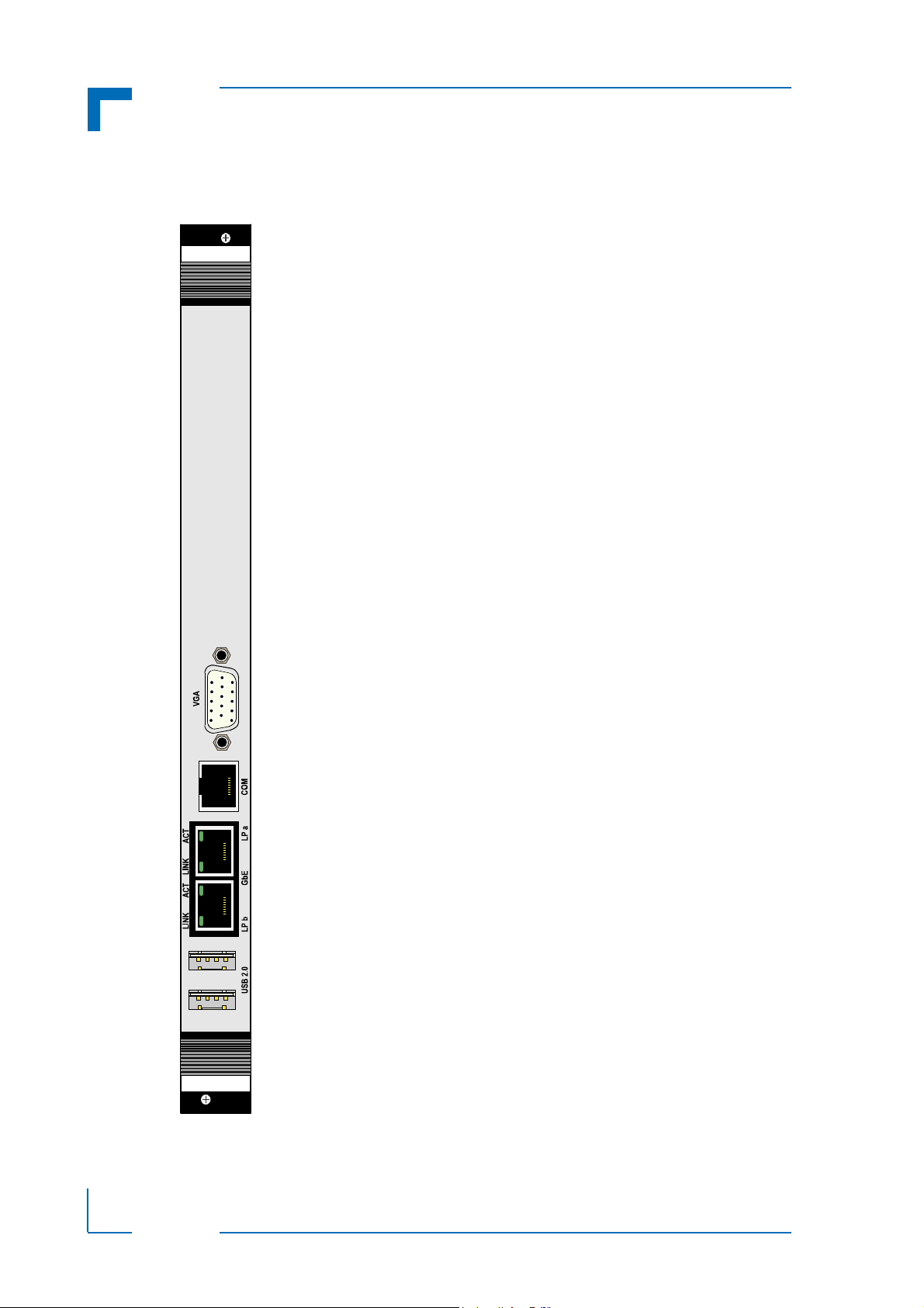
1.2.2 Front Panel
Figure 1-2: CP-RIO6-001-HD-VGA Front Panel
Page 1 - 4 ID 1052-4138, Rev. 1.0
Page 19

CP-RIO6-001-HD-VGA Introduction
DVI-D
J11
VGA
J20
COMA
J19
1
1
J6
J7
1
2
10
9
17
J8
COMB
J15
SATA
FANS
S1
HDD/SSD
rJ3
rJ5
rJ4
GbE
B
GbE
A
J18
J13
SATA
USB
USB
Magn.
Magn.
1.2.3 Board Layout
Figure 1-3: CP-RIO6-001-HD-VGA Board Layout – Front View
ID 1052-4138, Rev. 1.0 Page 1 - 5
Page 20

Introduction CP-RIO6-001-HD-VGA
Note ...
When additional components are installed, refer
to their operational specifications as this will influence the modules’ operational and storage temperature.
1.3 Technical Specification
Table 1-1: CP-RIO6-001-HD-VGA Main Specifications
CP-RIO6-001-HD-VGA SPECIFICATIONS
Analog Video VGA: 15-pin, D-Sub connector, J20
Ethernet Two Gigabit Ethernet interfaces implemented as a dual RJ-45 connector,
J18A/B
USB Two USB 2.0 interfaces on type A connectors, J16 and J17
Interfaces
Front Panel
COM One COM interface implemented as a single RJ45 connector, J19
SATA Two SATA interfaces implemented as two onboard connectors:
• One SATA connector, J13, for connecting a SATA device via a
SATA cable
• One SATA connector, J15, for installing an optional 2.5” SATA
HDD/SSD
USB One onboard connector, J14, for connecting one USB 2.0 NAND Flash
module
COM One COM port implemented as one 10-pin, 2.54 mm onboard connector,
J8
Fan Two fan connectors, J6 and J7, with sense inputs for monitoring the fan
Onboard Interfaces
CompactPCI Three CompactPCI connectors, rJ3, rJ4 and rJ5, for connecting the mod-
GPIO Two GPIO interfaces on the two-pin connectors J10 and J11
Temperature Range Operational: 0°C to +60°C Standard
General
Mechanical 6U, 4HP, CompactPCI-compliant form factor
Dimensions 233.35 mm x 80 mm
speed
ule to the backplane
-40°C to +85°C E2 (optional)
Storage: -55°C to +85°C Without any additional components
Board Weight 228 g (without USB NAND Flash module and/or HDD/SSD)
Page 1 - 6 ID 1052-4138, Rev. 1.0
Page 21

CP-RIO6-001-HD-VGA Introduction
1.4 Standards
The CP-RIO6-001-HD-VGA complies with the requirements of the following standards:
Table 1-2: Standards for the CP-RIO6-001-HD-VGA
TYPE ASPECT STANDARD REMARKS
CE Emission EN55022
EN61000-6-3
Immission EN55024
EN61000-6-2
Electrical Safety EN60950-1 --
Mechanical Mechanical Dimen-
sions
Environmental Climatic Humidity IEC60068-2-78 93% RH at 40°C, non-condensing
WEEE Directive 2002/96/EC Waste electrical and electronic equipment
RoHS Directive 2002/95/EC Restriction of the use of certain hazardous
Vibration
(Sinusoidal)
Single Shock IEC60068-2-27 Ruggedized version test parameters:
IEEE 1101.10 --
IEC60068-2-6 Ruggedized version test parameters:
--
--
substances in electrical and electronic
equipment
• 10-300 (Hz) frequency range
• 2 (g) acceleration
• 1 (oct/min) sweep rate
• 10 cycles/axis
• 3 axes
• 30 (g) acceleration
• 9 (ms) shock duration half sine
• 3 number of shocks per direction (total:
18)
• 6 directions
• 5 (s) recovery time
Permanent Shock IEC60068-2-29 Ruggedized version test parameters:
• 15 (g) acceleration
• 11 (ms) shock duration half sine
• 500 number of shocks per direction
• 6 directions
• 1 (s) recovery time
ID 1052-4138, Rev. 1.0 Page 1 - 7
Page 22

Introduction CP-RIO6-001-HD-VGA
Note ...
Kontron performs comprehensive environmental testing of its products in accordance with applicable standards.
Customers desiring to perform further environmental testing of Kontron products must contact Kontron for assistance prior to performing any such testing.
This is necessary, as it is possible that environmental testing can be destructive
when not performed in accordance with the applicable specifications.
In particular, for example, boards without conformal coating must not be
exposed to a change of temperature exceeding 1K/minute, averaged over a
period of not more than five minutes. Otherwise, condensation may cause irreversible damage, especially when the board is powered up again.
Kontron does not accept any responsibility for damage to products resulting
from destructive environmental testing.
1.5 Related Publications
The following publications contain information relating to the CP-RIO6-001-HD-VGA.
Table 1-3: Related Publications
PRODUCT PUBLICATION
CompactPCI Systems and
Boards
All Kontron products Product Safety and Implementation Guide, ID 1021-9142
CompactPCI Specification 2.0, Rev. 3.0
Kontron CompactPCI Backplane Manual, ID 24229
Page 1 - 8 ID 1052-4138, Rev. 1.0
Page 23

CP-RIO6-001-HD-VGA Functional Description
Chapter 1
2
Functional Description
ID 1052-4138, Rev. 1.0 Page 2 - 1
Page 24

Functional Description CP-RIO6-001-HD-VGA
This page has been intentionally left blank.
Page 2 - 2 ID 1052-4138, Rev. 1.0
Page 25

CP-RIO6-001-HD-VGA Functional Description
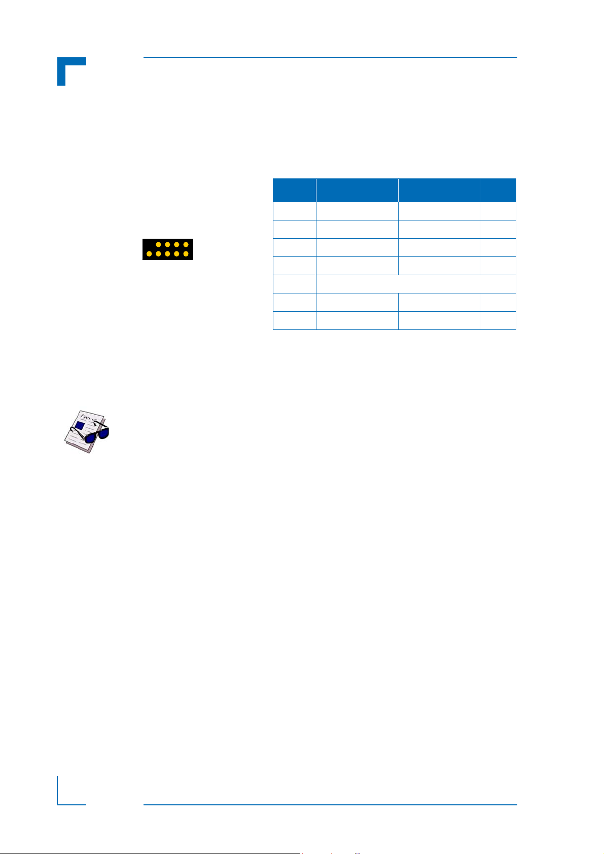
Figure 2-1: USB Con. J16 and J17
J17
J16
1324
1324
Table 2-1: USB Con. J16 and J17 Pinout
PIN SIGNAL FUNCTION I/O
1VCC VCC --
2 UV0- Differential USB- I/O
3 UV0+ Differential USB+ I/O
4GND GND --
2. Functional Description
2.1 Board Interfaces
2.1.1 USB Interfaces
The CP-RIO6-001-HD-VGA rear I/O module supports three USB 2.0 ports, two on the front I/O
and one onboard for the USB NAND Flash module. All ports are high-speed, full-speed, and
low-speed capable. One USB peripheral may be connected to each port. For connecting more
USB devices to the CP-RIO6-001-HD-VGA than there are available ports, an external USB hub
is required.
Note ...
The USB host interfaces can be used with maximum 500 mA continuous load
current as specified in the Universal Serial Bus Specification, Revision 2.0.
Short-circuit protection is provided. All the signal lines are EMI-filtered.
Note ...
The rear I/O interface supports the USB 1.1 and USB 2.0 standards. For USB
2.0 it is strongly recommended to use a cable length not exceeding 3 meters.
2.1.1.1 Front Panel USB Connectors J16 and J17
On the front panel of the CP-RIO6-001-HD-VGA rear I/O module, there are two USB interfaces
implemented on two 4-pin connectors with the following pinout:
ID 1052-4138, Rev. 1.0 Page 2 - 3
Page 26
Functional Description CP-RIO6-001-HD-VGA
Figure 2-2: USB NAND Flash Con. J14
1
210
9
Table 2-2: USB NAND Flash Con. J14 Pinout
PIN SIGNAL FUNCTION I/O
1VCC VCC --
3 UV0- Differential USB- I/O
5 UV0+ Differential USB+ I/O
7GND GND --
9Key
2, 4, 6, 8 NC Not connected --
10 Res. Reserved --
2.1.1.2 Onboard USB NAND Flash Connector J14
The CP-RIO6-001-HD-VGA rear I/O module has one onboard USB interface implemented on a
9-pin connector, J14, with the following pinout.
The J14 connector is used to connect an optional USB 2.0 NAND Flash module qualified by
Kontron. The USB 2.0 NAND Flash module is a USB 2.0-based NAND Flash drive with a builtin full hard-disk emulation and a high data transfer rate. It is optimized for embedded systems
providing high performance, reliability and security.
Note ...
Only qualified USB 2.0 NAND Flash modules from Kontron are authorized for
use with the CP-RIO6-001-HD-VGA. Use of unqualified USB 2.0 NAND Flash
modules or improper installation will void the warranty and may result in damage to the CP-RIO6-001-HD-VGA or the system.
Page 2 - 4 ID 1052-4138, Rev. 1.0
Page 27
CP-RIO6-001-HD-VGA Functional Description
1
6
11
15
10
5
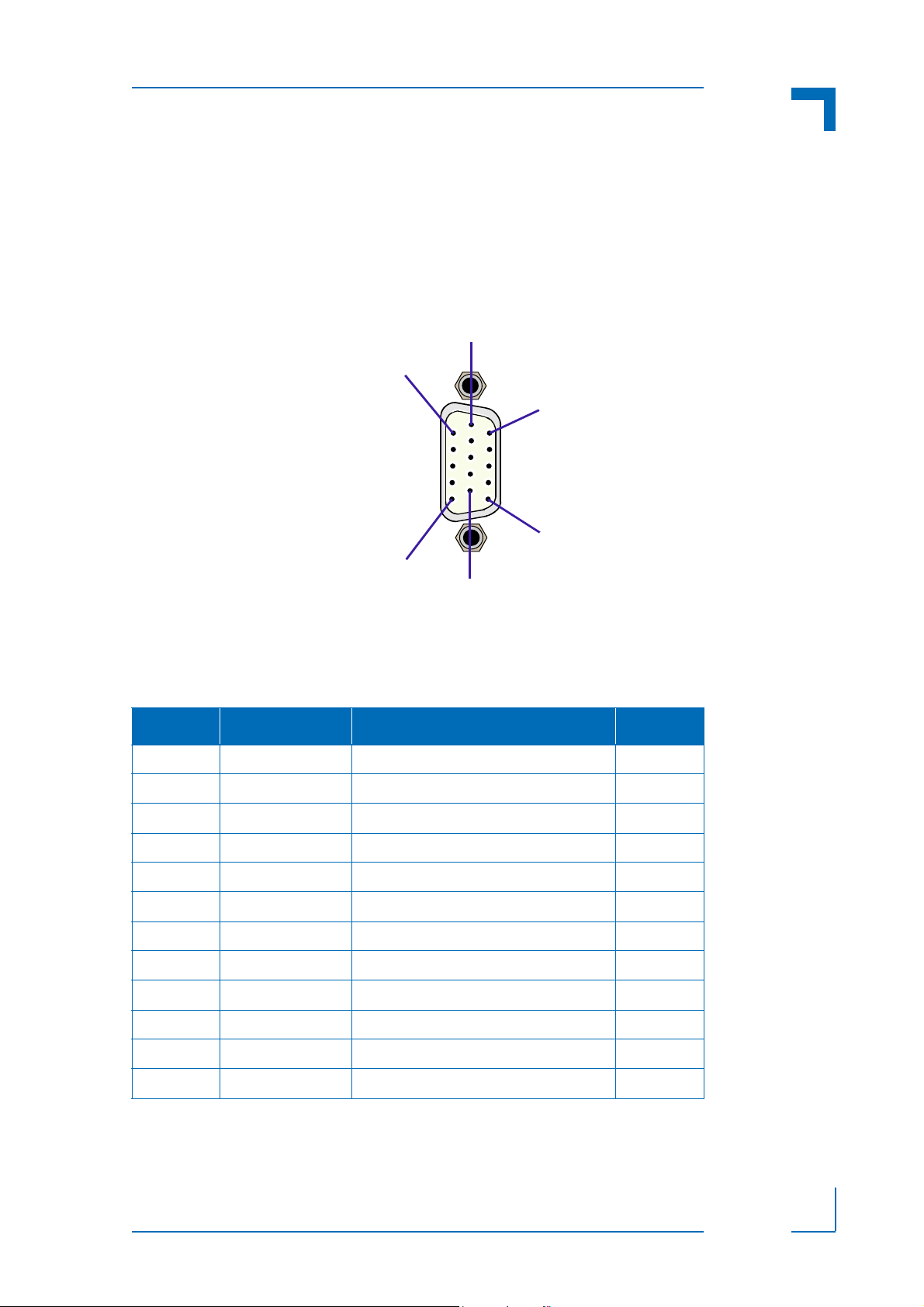
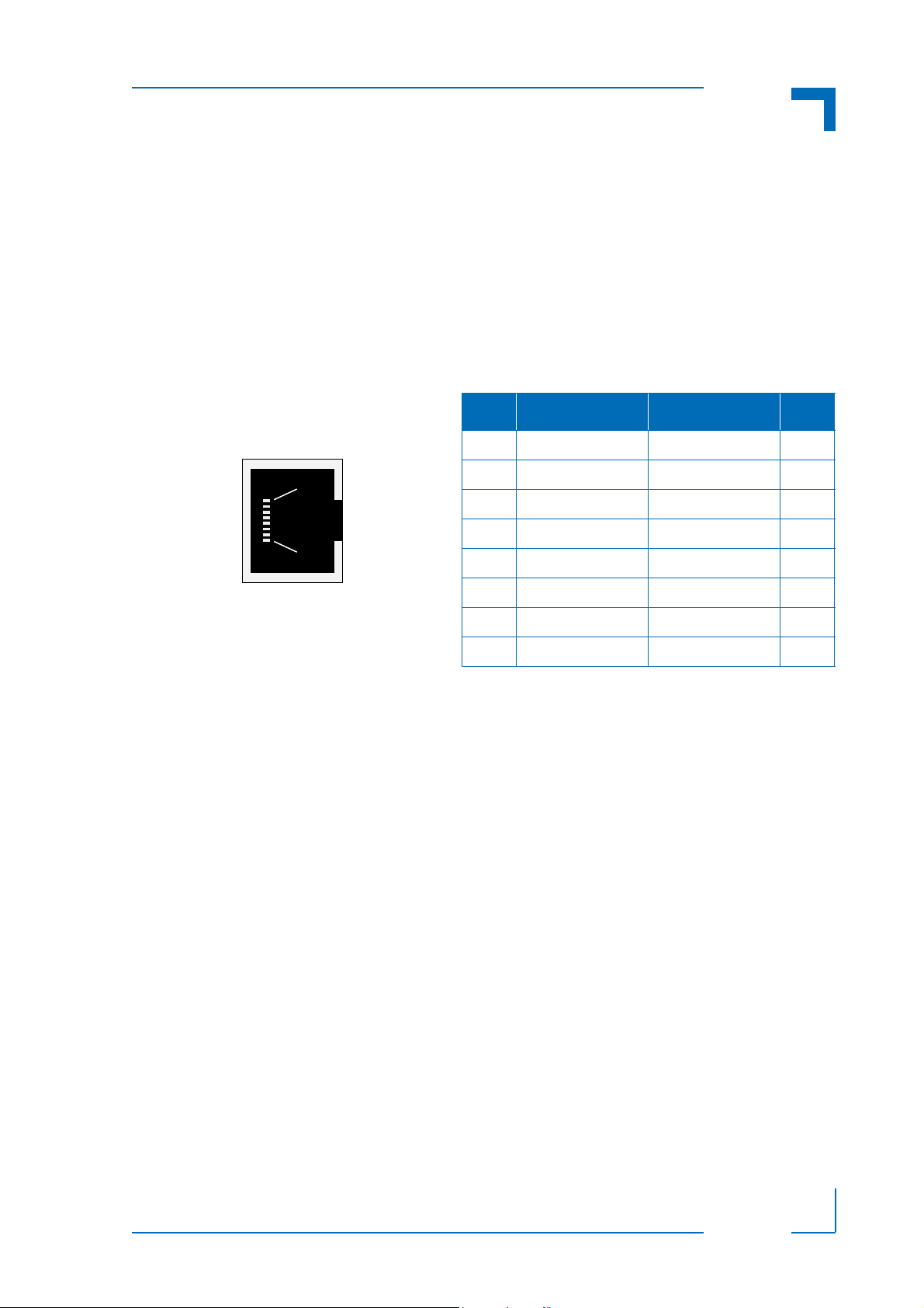
2.1.2 VGA Interface
The CP-RIO6-001-HD-VGA provides one 15-pin, female connector, J20, on the front panel.
This connector is used to connect an analog VGA (CRT) monitor to the module.
The following figure illustrates the D-Sub VGA connector J20.
Figure 2-3: D-Sub VGA Connector J20
The following table indicates the pinout of the D-Sub VGA connector J20
Table 2-3: D-Sub VGA Connector J20 Pinout
PIN SIGNAL FUNCTION I/O
1 Red Red video signal output O
2 Green Green video signal output O
3 Blue Blue video signal output O
4 NC Not connected --
5 - 8 GND Signal ground --
9 VCC Power +5V, 0.5 A fuse protection O
10 GND Signal ground --
11 NC Not connected --
12 SDA I²C data (EDID) I/O
13 Hsync Horizontal synchronization TTL Out
14 Vsync Vertical synchronization TTL Out
15 SCL I²C clock (EDID) I/O
.
ID 1052-4138, Rev. 1.0 Page 2 - 5
Page 28

Functional Description CP-RIO6-001-HD-VGA
Figure 2-4: Dual Gigabit Ether-
net Con. J18A/B
J18B
J18A
8
1
8
1
Table 2-4: Pinout of Dual GbE Connector J18A/B
PIN
MDI / STANDARD ETHERNET CABLE
10BASE-T 100BASE-TX 1000BASE-T
I/O SIGNAL I/O SIGNAL I/O SIGNAL
1 O TX+ O TX+ I/O BI_DA+
2 O TX- O TX- I/O BI_DA-
3 I RX+ I RX+ I/O BI_DB+
4----I/OBI_DC+
5----I/OBI_DC-
6 I RX- I RX- I/O BI_DB-
7----I/OBI_DD+
8----I/OBI_DD-
2.1.3 Gigabit Ethernet Interfaces
The CP-RIO6-001-HD-VGA provides a Gigabit Ethernet interface implemented as one dual,
RJ-45 Ethernet connector J18A/B.
Note ...
The Ethernet transmission can operate effectively with structured cable that
meets CAT5 cable or higher specifications.
Ethernet LED Status
ACT (green): This LED monitors network connection and activity. When this LED is lit, it means
that a link has been established. The LED blinks when network packets are sent or received
through the RJ-45 port. When this LED is not lit, there is no link established.
LINK (green): This LED lights up to indicate a successful 100Base-TX connection. When not
lit and the ACT-LED is active, the connection is operating at 1000Base-T or 10Base-T.
Page 2 - 6 ID 1052-4138, Rev. 1.0
Page 29
CP-RIO6-001-HD-VGA Functional Description
Figure 2-5: SATA Con. J13
71
Table 2-5: SATA Connector J13 Pinout
PIN SIGNAL DESCRIPTION I/O
1 GND Ground signal --
2 SATA_TX+ Differential Transmit + O
3 SATA_TX- Differential Transmit - O
4 GND Ground signal --
5 SATA_RX- Differential Receive - I
6 SATA_RX+ Differential Receive + I
7 GND Ground signal --
2.1.4 Serial ATA Interfaces
The CP-RIO6-001-HD-VGA provides two SATA interfaces, one for connecting a standard 2.5"
SATA HDD/SSD and one for connecting a SATA device via a SATA cable.
The SATA interfaces are capable of supporting SATA 1.5 Gb/s and SATA 3.0 Gb/s signaling.
2.1.4.1 SATA Connector J13
The CP-RIO6-001-HD-VGA rear I/O module is equipped with a SATA connector, J13, used to
connect a standard SATA device to the rear I/O module via a SATA cable. The rear I/O module
will not exceed the thickness of 4HP when a Serial ATA cable is used.
The following figure and table provide pinout information for the SATA connector J13.
Note ...
To ensure secure connectivity, the SATA connector supports the use of SATA
cables with a locking latch.
ID 1052-4138, Rev. 1.0 Page 2 - 7
Page 30
Functional Description CP-RIO6-001-HD-VGA
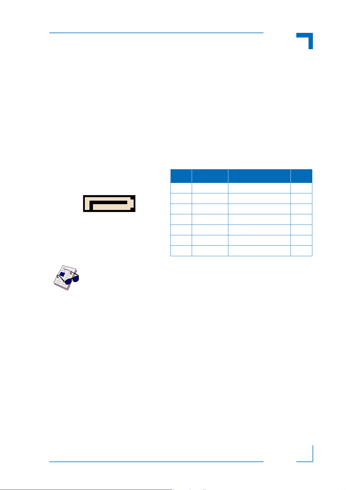
Figure 2-6: SATA Connector J15
Table 2-6: SATA Connector J15 Pinout
PIN SIGNAL FUNCTION I/O
Signal Segment Key
S1 GND Ground signal --
S2 SATA_TX+ Differential Transmit+ I
S3 SATA_TX- Differential Transmit- I
S4 GND Ground signal --
S5 SATA_RX- Differential Receive- O
S6 SATA_RX+ Differential Receive+ O
S7 GND Ground signal --
Signal Segment “L”
Central Connector Polarizer
Power Segment “L”
P1 3.3V 3.3V power --
P2 3.3V 3.3V power --
P3 3.3V 3.3V power --
P4 GND Ground signal --
P5 GND Ground signal --
P6 GND Ground signal --
P7 5V 5V power --
P8 5V 5V power --
P9 5V 5V power --
P10 GND Ground signal --
P11 RES Reserved --
P12 GND Ground signal --
P13 12V 12 V power --
P14 12V 12 V power --
P15 12V 12 V power --
Power Segment Key
Signal
Segment
Power
Segment
S1
S7
P1
P15
2.1.4.2 SATA Connector J15
The CP-RIO6-001-HD-VGA rear I/O module is equipped with the SATA connector J15 used to
connect a 2.5” SATA HDD/SSD to the rear I/O module. The connector is divided into two segments, a signal segment and a power segment.
Page 2 - 8 ID 1052-4138, Rev. 1.0
Page 31
CP-RIO6-001-HD-VGA Functional Description
Figure 2-7: Serial Con. J19 (COMA)
1
8
Table 2-6: Serial Con. J19 (COMA) Pinout
PIN SIGNAL FUNCTION I/O
1 RTS Request to send O
2 DTR Data terminal ready O
3 TXD Transmit data O
4 GND Signal ground --
5 GND Signal ground --
6 RXD Receive data I
7 DSR Data set ready I
8 CTS Clear to send I
2.1.5 COM Interfaces
The CP-RIO6-001-HD-VGA rear I/O module provides two COM ports for connecting RS-232
(COMA) and RS-232/RS-422 (COMB) devices, depending on the CPU board. The following
figures and tables provide pinout information for the COM connector J8 (COM B) and J19
(COMA).
2.1.5.1 COMA Port
The COMA port is available on the front panel as a serial RS-232, 8-pin, RJ-45 connector
ID 1052-4138, Rev. 1.0 Page 2 - 9
Page 32
Functional Description CP-RIO6-001-HD-VGA
12
10 9
Figure 2-9: Fan Control Con.
J6 and J7
J6
FAN2
J7
FAN1
1
1
Table 2-8: Fan Control Con. J6 and J7 Pinout
PIN SIGNAL DESCRIPTION I/O
1 GND Signal ground --
2 PWM Fan Supply Voltage (12V) O
3 SENSE Fan Sense I
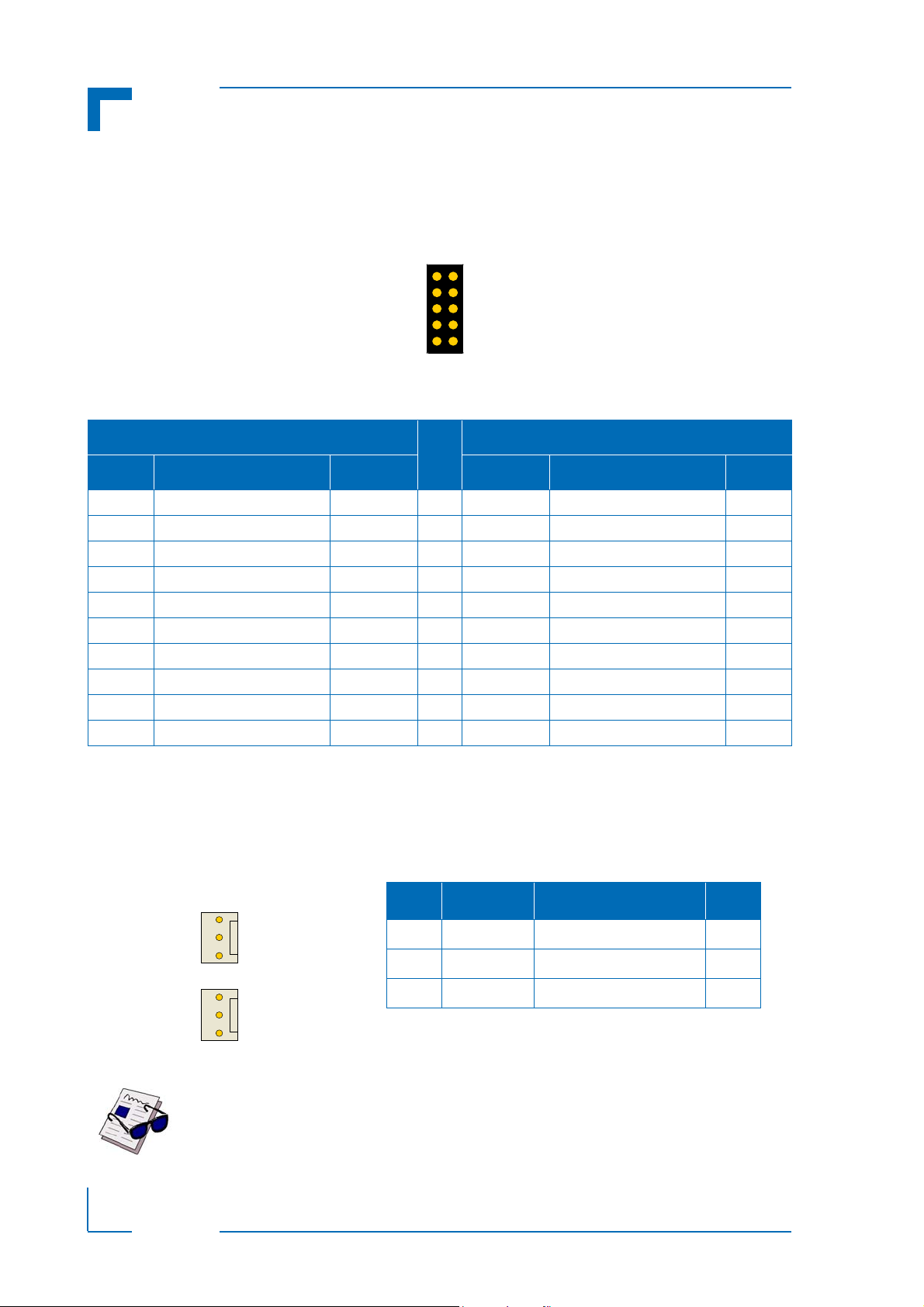
2.1.5.2 COMB Port
The COMB port is realized using an onboard 10-pin male header type connector, J8.
Figure 2-8: Serial Port Connector J8
Table 2-7: Serial Port Connector J8 (RS-232/RS-422) Pinout
RS-232 SIGNALING
RS-422 SIGNALING
PIN
I/O DESCRIPTION SIGNAL SIGNAL DESCRIPTION I/O
I Data carrier detect DCD 1 RX+ Receive data + I
I Data send request DSR 2 RX- Receive data - I
I Receive data RXD 3 NC Not connected --
O Request to send RTS 4 NC Not connected --
O Transmit data TXD 5 TX+ Transmit data + O
I Clear to send CTS 6 TX- Transmit data - O
O Data terminal ready DTR 7 NC Not connected --
I Ring indicator RI 8 NC Not connected --
-- Signal ground GND 9 GND Signal ground --
-- Not connected NC 10 NC Not connected --
2.1.6 FAN Connectors
The CP-RIO6-001-HD-VGA has two 3-pin, onboard fan connectors, J6 and J7, used to connect
two external cooling fans.
Page 2 - 10 ID 1052-4138, Rev. 1.0
Note ...
The maximum allowable continuous load current on each fan interface is 300 mA.
Page 33

CP-RIO6-001-HD-VGA Functional Description
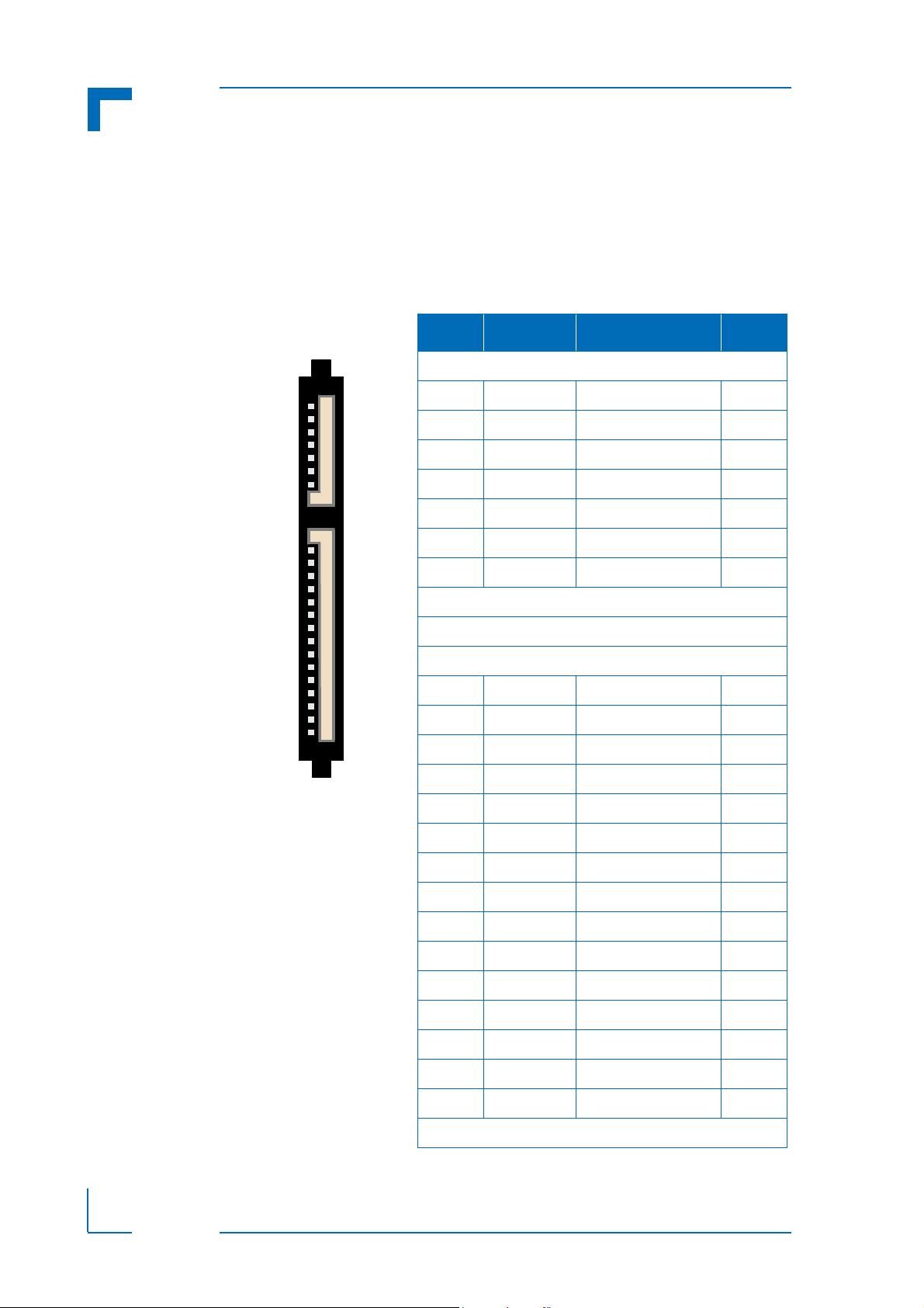
1
19
1
22
1
25
rJ5
rJ4
rJ3
ABCDE
Z F
Note:
Pinrow F: GND
Pinrow Z: NC
2.1.7 Rear I/O Interface on cPCI Connectors: rJ3, rJ4 and rJ5
The CP-RIO6-001-HD-VGA rear I/O module is equipped with three CompactPCI rear I/O connectors: rJ3, rJ4 and rJ5.
Note ...
To support the rear I/O feature, a 6U CompactPCI backplane with rear I/O support as well as a compatible and correctly configured CPU board are required.
Do not plug the CP-RIO6-001-HD-VGA in a backplane without rear I/O support.
Failure to comply with the above will result in damage to the CP-RIO6-001-HDVGA.
Figure 2-10: Rear I/O CompactPCI Connectors rJ3, rJ4 and rJ5
ID 1052-4138, Rev. 1.0 Page 2 - 11
Page 34

Functional Description CP-RIO6-001-HD-VGA
Table 2-9: Rear I/O CompactPCI Connector rJ3 Pinout
PIN Z A B C D E F
19 NC RIO_VCC RIO_VCC RIO_3.3V RIO_+12V RIO_-12V GND
18 NC LPa_DA+ LPa_DA- GND LPa_DC+ LPa_DC- GND
17 NC LPa_DB+ LPa_DB- GND LPa_DD+ LPa_DD- GND
16 NC LPb_DA+ LPb_DA- GND LPb_DC+ LPb_DC- GND
15 NC LPb_DB+ LPb_DB- GND LPb_DD+ LPb_DD- GND
14 NC LPa:LINK LPb:LINK NC NC FAN:SENSE2 GND
13 NC LPa:ACT LPb:ACT NC NC FAN:SENSE1 GND
12 NC NC NC GND NC NC GND
11 NC NC NC GND NC NC GND
10 NC USB1:VCC USB0:VCC GND RSV USB2:VCC GND
9 NC USB1:D- USB1:D+ GND RSV RSV GND
8 NC USB0:D- USB0:D+ GND USB2:D- USB2:D+ GND
7 NC RIO_3.3V GPIO: * GPIO: * GPIO: * NC GND
6 NC VGA:RED VGA:GREEN VGA:SD1 RSV NC GND
5 NC VGA:BLUE VGA:HSYNC VGA:VSYNC VGA:SCL NC GND
4 NC SPB:RI
SPB:NC
3 NC SPB:RTS
SPB:NC
2 NC SPA:RI SPA:DTR S PA:CTS SPA:TX NC G ND
1 NC SPA:RTS SPA:RX SPA:DSR SPA:DCD ID1 GND
SPB:DTR
SPB:NC
SPB:RX
SPB:NC
SPB:CTS
SPB:TX-
SPB:DSR
SPB:RX-
SPB:TX
SPB:TX+
SPB:DCD
SPB:RX+
NC GND
NC GND
Warning!
The RIO_XXX signals are power supply INPUTS to supply the rear I/O module
with power from the CPU board. These pins MUST NOT be connected to any
other power source, either within the backplane itself or within a rear I/O module.
Failure to comply with the above will result in damage to your board.
The following table describes the signals of the rJ3 connector used on the CP-RIO6-001-HD-VGA.
Table 2-10: Rear I/O CompactPCI Connector rJ3 Signals
SIGNAL DESCRIPTION SIGNAL DESCRIPTION
SPA COMA Signaling RS-232 LPb Rear I/O LAN Port A
SPB COMB Signaling RS-232/RS-422 VGA Analog Video Signaling
USB0 to USB2 USB Port Signaling FAN Fan Sensoring
GPIO: *
LPa Rear I/O LAN Port B
Page 2 - 12 ID 1052-4138, Rev. 1.0
General Purpose IO Signaling: on
request only (direction depends
on CPU board functionality)
Page 35

CP-RIO6-001-HD-VGA Functional Description
Table 2-11: Rear I/O CompactPCI Connector rJ4 Pinout
PIN Z A B C D E F
25 NC RSV RSV GND RSV RSV GND
24 NC RSV RSV GND RSV RSV GND
23 NC NC RIO_VCC GND NC RIO_3.3V GND
22 NC RSV RSV GND RSV RSV GND
21 NC RSV RSV GND RSV RSV GND
20 NC GND GND GND GND GND GND
19 NC RSV RSV GND RSV RSV GND
18 NC RSV RSV GND RSV RSV GND
17 NC GND GND GND GND GND GND
16 NC RSV RSV GND RSV RSV GND
15 NC RSV RSV GND RSV RSV GND
12-14 Key Area
11 NC RSV RSV GND RSV RSV GND
10 NC RSV RSV GND RSV RSV GND
9 NC GND GND GND GND GND GND
8 NC RSV RSV GND RSV RSV GND
7 NC RSV RSV GND RSV RSV GND
6 NC GND GND GND GND GND GND
5 NC RSV RSV GND RSV RSV GND
4 NC RSV RSV GND RSV RSV GND
3 NC GND GND GND GND GND GND
2 NC RSV RSV GND RSV RSV GND
1 NC RSV RSV GND RSV RSV GND
Warning!
The RIO_XXX signals are power supply INPUTS to supply the rear I/O module
with power from the CPU board. These pins MUST NOT be connected to any
other power source, either within the backplane itself or within a rear I/O module.
Failure to comply with the above will result in damage to your board.
ID 1052-4138, Rev. 1.0 Page 2 - 13
Page 36

Functional Description CP-RIO6-001-HD-VGA
Table 2-12: Rear I/O CompactPCI Connector rJ5 Pinout
PIN Z A B C D E F
22 NC GPIO: * PWM1:OUT GND PWM2:OUT NC GND
21 NC NC NC GND NC SYS_WP GND
20 NC GPIO:0 NC GND GPIO:1 NC GND
19 NC GND GND GND NC NC GND
18 NC NC NC GND GND GND GND
17 NC NC NC GND NC NC GND
16 NC NC NC GND GPIO: * GPIO: * GND
15 NC NC NC GND NC NC GND
14 NC GND GND GND GND GND GND
13 NC NC NC NC NC NC GND
12 NC NC NC NC NC NC GND
11 NC NC NC NC NC NC GND
10 NC NC NC NC NC NC GND
9 NC GND GND GND GND GND GND
8 NC SATA3:TX+ SATA3:TX- GND SATA3:RX+ SATA3:RX- GND
7 NC GND GND GND GND GND GND
6 NC RSV RSV GND RSV RSV GND
5 NC GND GND GND GND GND GND
4 NC SATA1:TX+ SATA1:TX- GND SATA1:RX+ SATA1:RX- GND
3 NC GND GND GND GND GND GND
2 NC RSV RSV GND RSV RSV GND
1 NC GND GND GND GND GND GND
The following table describes the signals of the rJ5 connector.
Table 2-13: Rear I/O CompactPCI Rear I/O Connector rJ5 Signals
SIGNAL DESCRIPTION
SATA1 and
SATA3
GPIO
GPIO *
PWM Pulse width modulation output for fan
Page 2 - 14 ID 1052-4138, Rev. 1.0
SATA Port 1 and Port 3 Signaling
General Purpose IO Signaling (direction and voltage leveling depends
on CPU board functionality)
General Purpose IO Signaling: on request only (direction and voltage
leveling depends on CPU board functionality)
Page 37

CP-RIO6-001-HD-VGA Functional Description
2.1.8 GPIO Connectors J10 and J11
The CP-RIO6-001-HD-VGA has two GPIO interfaces, one on J10 (GPIO:0) and one on J11
(GPIO:1). Pin 1 is the signal and pin 2 is ground. Refer to figure 1-3 for the connector locations
and pin orientation.
Signal direction, input or output and voltage leveling is a function of the CPU. Filtering and
signal protection must be done by the system integrator.
2.2 System Write Protection Jumper J12
When set, this jumper signals the host CPU to invoke system write protection. If this protection
is required, please contact Kontron before implementing.
Table 2-14: J12 Jumper Setting for System Write Protection
J12 DESCRIPTION
Open System Write Protection not enabled
Closed System Write Protection enabled
The default setting is indicated by using italic bold.
ID 1052-4138, Rev. 1.0 Page 2 - 15
Page 38

Functional Description CP-RIO6-001-HD-VGA
This page has been intentionally left blank.
Page 2 - 16 ID 1052-4138, Rev. 1.0
Page 39

CP-RIO6-001-HD-VGA Installation
Chapter 1
3
Installation
ID 1052-4138, Rev. 1.0 Page 3 - 1
Page 40

Installation CP-RIO6-001-HD-VGA
This page has been intentionally left blank.
Page 3 - 2 ID 1052-4138, Rev. 1.0
Page 41
CP-RIO6-001-HD-VGA Installation
3. Installation
The CP-RIO6-001-HD-VGA has been designed for easy installation. However, the following
standard precautions, installation procedures, and general information must be observed to ensure proper installation and to preclude damage to the CP-RIO6-001-HD-VGA, other system
components, or injury to personnel.
3.1 Safety Requirements
The following safety precautions must be observed when installing or operating the CP-RIO6001-HD-VGA. Kontron assumes no responsibility for any damage resulting from failure to comply with these requirements.
Caution!
Ensure that the system main power is removed prior to installing or removing
the CP-RIO6-001-HD-VGA. Ensure that there are no other external voltages
or signals being applied to the CP-RIO6-001-HD-VGA or other boards within
the system. Failure to do so could endanger your life or health and may
damage the CP-RIO6-001-HD-VGA or other system components including
process-side signal conditioning equipment.
ESD Equipment!
The CP-RIO6-001-HD-VGA contains electrostatically sensitive devices.
Please observe the necessary precautions to avoid damage to the CP-RIO6001-HD-VGA:
• Discharge your clothing before touching the assembly. Tools must be discharged before use.
• Do not touch components, connector-pins or traces.
• If working at an anti-static workbench with professional discharging
equipment, please do not omit to use it.
ID 1052-4138, Rev. 1.0 Page 3 - 3
Page 42

Installation CP-RIO6-001-HD-VGA
3.2 Rear I/O Module Installation Procedures
To perform an installation of the rear I/O module in a system, proceed as follows:
1. Ensure that the safety requirements indicated Chapter 3.1 are observed.
Warning!
Failure to comply with the instruction below may cause damage to the
rear I/O module or result in improper system operation.
2. Ensure that the rear I/O module is compatible with the CPU board and the backplane prior to installation.
Note ...
Ensure that the system components are properly configured for use with
the rear I/O module.
3. If appropriate, ensure that the onboard peripheral devices are properly installed prior to
installation.
4. Ensure that no power is applied to the system before proceeding.
Warning!
Even though power may be removed from the system, the rear I/O module’s front panel cables may have power applied which comes from an external source.
In addition, these cables may be connected to devices that can be damaged by electrostatic discharging or short-circuiting of pins.
It is the responsibility of the system designer or integrator to ensure that
appropriate measures are taken to preclude damage to the system or injury to personnel which may arise from the handling of these cables (connecting or disconnecting).
Kontron disclaims all liability for damages or injuries resulting from failure
to comply with the above.
Warning!
When performing the next step, DO NOT push the rear I/O module into the
backplane connectors. Use the ejector handles to seat the rear I/O module
into the backplane connectors.
5. Carefully insert the rear I/O module into the slot designated by the application requirements for the rear I/O module until it makes contact with the backplane connectors.
6. Using both ejector handles, engage the rear I/O module with the backplane. When the
ejector handles are locked, the rear I/O module is engaged.
7. Fasten the two front panel retaining screws.
8. Connect all external interfacing cables to the rear I/O module as required.
9. Ensure that the rear I/O module and all required interfacing cables are properly secured.
The rear I/O module is now ready for operation.
Page 3 - 4 ID 1052-4138, Rev. 1.0
Page 43

CP-RIO6-001-HD-VGA Installation
3.3 Rear I/O Module Removal Procedures
To remove the rear I/O module proceed as follows:
1. Ensure that the safety requirements indicated in Chapter 3.1 are observed.
Warning!
Care must be taken when applying the procedures below to ensure that
neither the rear I/O module nor system boards are physically damaged by
the application of these procedures.
2. Ensure that no power is applied to the system before proceeding.
Warning!
Even though power may be removed from the system, the rear I/O module’s front panel cables may have power applied which comes from an external source.
In addition, these cables may be connected to devices that can be damaged by electrostatic discharging or short-circuiting of pins.
It is the responsibility of the system designer or integrator to ensure that
appropriate measures are taken to preclude damage to the system or injury to personnel which may arise from the handling of these cables (connecting or disconnecting).
Kontron disclaims all liability for damages or injuries resulting from failure
to comply with the above.
3. Disconnect any interfacing cables that may be connected to the rear I/O module.
4. Unscrew the two front panel retaining screws.
5. Disengage the rear I/O module from the backplane by first unlocking the ejection handles
and then by pressing the handles as required until the rear I/O module is disengaged.
6. After disengaging the rear I/O module from the backplane, pull it out of the slot.
7. Dispose of the rear I/O module as required.
3.4 Installation of Peripheral Devices
The CP-RIO6-001-HD-VGA is designed to accommodate a variety of peripheral devices whose
installation varies considerably. The following chapters provide information regarding installation aspects and not detailed procedures.
3.4.1 USB Device Installation
The CP-RIO6-001-HD-VGA supports all USB Plug and Play computer peripherals (e.g.
keyboard, mouse, printer, etc.).
Note ...
All USB devices may be connected or removed while the host or other
peripherals are powered up.
ID 1052-4138, Rev. 1.0 Page 3 - 5
Page 44

Installation CP-RIO6-001-HD-VGA
3.4.2 USB 2.0 NAND Flash Module Installation
One
USB 2.0 NAND Flash module may be connected to the
board USB 2.0 NAND Flash connector, J14.
The USB 2.0 NAND Flash module must be physically installed on the CP-RIO6-001-HD-VGA
prior to installation of the rear I/O module in a system.
During installation it is necessary to ensure that the USB 2.0 NAND Flash module is properly
seated in the onboard USB 2.0 NAND Flash connector, i.e. the pins are correctly aligned and
not bent.
Note ...
Only qualified USB 2.0 NAND Flash modules from Kontron are authorized for
use with the CP-RIO6-001-HD-VGA. Use of unqualified USB 2.0 NAND Flash
modules or improper installation will void the warranty and may result in damage to the CP-RIO6-001-HD-VGA or the system.
If this module is ordered separately, it is delivered with two screws and a standoff to assemble
the module to the CP-RIO6-001-HD-VGA
module itself and fixate it with the second screw.
. To do this first install the standoff, then mount the
CP-RIO6-001-HD-VGA
via the on-
Refer to Figure 3-1 for placement of the USB 2.0 NAND Flash module.
3.4.3 Installation of an External Serial ATA Device
One external SATA device may be connected to the CP-RIO6-001-HD-VGA via the onboard
SATA connector J13 as well as the appropriate SATA cable.
Some symptoms of incorrectly installed SATA devices are:
• Device on a SATA channel does not spin up: check power cables and cabling. May also
result from a bad power supply or SATA device.
The SATA connector on the CP-RIO6-001-HD-VGA provides only a data connection.
The power for this device must be supplied by a separate connector. For further information, refer to the respective documentation of the device.
• SATA device fail message at boot-up: may be a bad cable or lack of power going to the
drive.
Warning!
The incorrect connection of power or data cables may damage the SATA
device and/or the CP-RIO6-001-HD-VGA.
Page 3 - 6 ID 1052-4138, Rev. 1.0
Page 45

CP-RIO6-001-HD-VGA Installation
USB 2.0
NAND
FLASH
2.5” Serial ATA
HDD
/
SSD
mounting
screws
mounting
screws
mounting
screws
standoff
3.4.4 Installation of a 2.5” SATA HDD/SSD Device
One 2.5” SATA HDD/SSD may be installed on the CP-RIO6-001-HD-VGA via the onboard
SATA connector J15. During installation it is necessary to ensure that the SATA device is correctly seated in the onboard SATA connector and properly secured via the four mounting
screws.
The following figure shows the placement of the 2.5” SATA HDD/SSD and the USB 2.0 NAND
Flash on the CP-RIO6-001-HD-VGA.
Figure 3-1: Placement of the Onboard Mass Storage Devices
Note ...
The CP-RIO6-001-HD-VGA supports SATA devices with a maximum start-up
current of 1.1 A (5.5 W) and a maximum operating current of 0.7 A (3.5 W) on
the 5 V voltage supply.
ID 1052-4138, Rev. 1.0 Page 3 - 7
Page 46

Installation CP-RIO6-001-HD-VGA
This page has been intentionally left blank.
Page 3 - 8 ID 1052-4138, Rev. 1.0
 Loading...