

Page 1
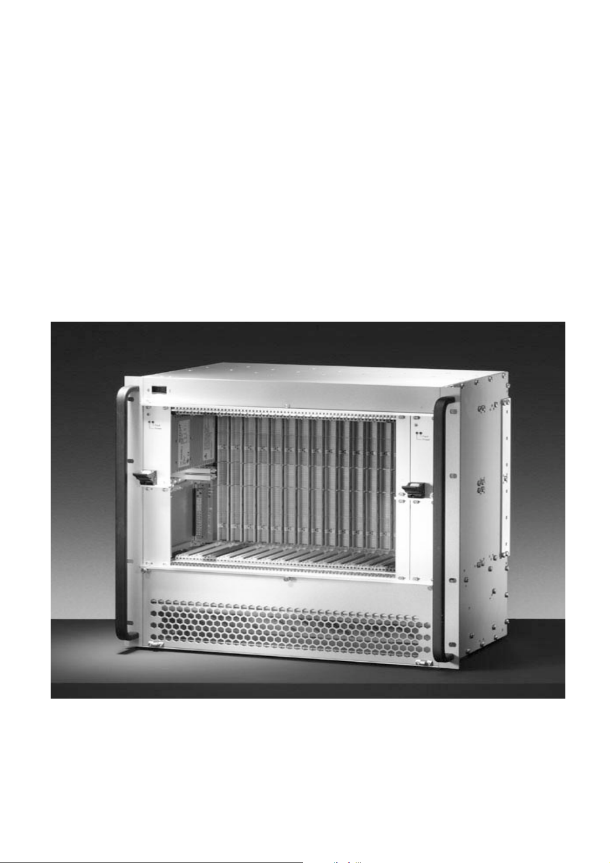
Benutzerinformation
Mikrocomputer
Aufbausystem
CPCI PICMG 2.16Einschubsystem 10 HE
User Information
Microcomputer
Packaging Systems
CPCI PICMG 2.16
subrack 10 U
CP-ASM10-PSB
Page 2

CP-ASM10-PSB
Contents
Contents English, page .............................................. 1.2
Page
1 Introduction ............................................................... 1.2
1.1 Please read immediately! ............................................ 1.2
1.2 Description .................................................................. 1.3
1.3 Safety instructions ....................................................... 1.3
1.4 Advice .......................................................................... 1.3
2 System overview ........................................................ 1.4
2.1 Mechanical configuration ............................................. 1.4
2.2 Assembly ..................................................................... 1.5
2.3 Starting-up the system ................................................. 1.5
2.4 Maintenance ................................................................ 1.5
3 Electrical configuration ............................................. 1.5
3.1 Cabling, general ........................................................... 1.5
3.2 Fan Control Module (FCM) .......................................... 1.6
4 Technical data ............................................................ 1.7
4.1 Mechanical data .......................................................... 1.7
4.2 Electrical data .............................................................. 1.7
4.2.1 Power supply ............................................................... 1.7
4.2.2 Fan Control Module (FCM) .......................................... 1.8
4.2.3 Fan .............................................................................. 1.8
4.2.4 Backplane .................................................................... 1.8
4.3 General data ................................................................ 1.8
4.4 Shielding attenuation curve europacPRO .................... 1.9
4.4.1 Measuring principle ..................................................... 1.9
4.4.2 Results ......................................................................... 1.9
5 Error correction ......................................................... 1.10
6 Replacement parts .................................................... 1.10
1 Introduction
1.1 Please read immediately!
This microcomputer packaging system is not a complete unit
which can be delivered directly to the end user; other items need to
be fitted. Before delivering the complete unit, the following checks
must be carried out according to the specifications:
does the assembled unit comply with the safety instructions
currently applicable in the country in which it is going to be
used?
are all the apertures of the case closed so that the user cannot
get into the case (finger test)?
Make sure that
all safety checks have been carried out on every unit,
the operator knows what safety measures have to be
undertaken (e.g. GND/earthing),
the overall unit complies with all other specifications at the
place of use and in the country in which it is going to be used,
e.g. interference limits, approval by the telecommunications
authorities.
The above assumes that the initial testing, completion and
final testing of the units have been carried out or at least
supervised by qualified technicians. These instructions are
directed exclusively to these qualified technicians.
Check the packing content. At least the following should be included:
1 bag of assembly parts for mounting the system subrack into
a case or cabinet
When the unit has been unpacked the safety and function
checks should be carried out immediately, see section
"Introduction – Safety instructions". No liability is accepted
for boards which have been destroyed by faulty operating
voltages!
If there are problems please contact your supplier or your local
Schroff representative, see back cover of this booklet.
7 Warranty conditions .................................................. 1.10
1.2
Page 3
CP-ASM10-PSB
1.2 Description
This microcomputer system consists of mechanics, backplane, fan
and power supply for a microprocessor system based on the CPCI
PICMG2.16bus. This microcomputer packaging system has been
designed for use in laboratories or in a manufacturing environment
where there are no extreme
conditions.
Please check the technical data of any parts which you wish to
assemble; they may restrict the air flow and the temperature.
This unit has no valid approval for the complete unit. This
can only be granted for the complete unit if approval is
granted for individual units or a batch. Such approvals are
carried out by VDE, TÜV, professional boards etc. according
to each application.
CAUTION!
The unit is designed in accordance with protection class 1!
It must therefore be operated only with protective GND/earth
connection!
1.3 Safety instructions
This microcomputer packaging system has been subjected to
extensive testing before delivery. However, this cannot guarantee
that the unit does not get damaged during transit. Check the
packaging and the CPCI unit before applying mains voltage to
ensure that your system can not be destroyed by faulty operating
voltages.
Caution:
The area of the system accessed after removing the mains/line
panels is not a user area! Parts which can be touched may be
exposed to dangerous voltages. Initial testing, completion, final
testing or maintenance and repairs must be carried out by trained engineers only.
The following tests have to be done before placing the
system in service:
Disconnect the main/line voltage!
1.4 Advice
Caution:
Attention
- please observe the safety instructions
- read operating instructions before system start-up!
- to be operated only on networks with PE conductor!
- put into service by qualified personnel only!
Safety instructions
Danger to life
are meant to
- save lives
- prevent accidents
- save trouble
Please make sure to keep these operating instructions. They
contain valuable information pertaining to safety.
They
- support operators, users, service staff and technical personnel
during preparatory work, installation and system start-up, and they
help understand the functions of the system
- give hints as to special operating conditions
- explain the displays and control elements
- inform about all essential technical data
Technical changes and upgrades will be implemented without
prior annoucement, provided that they serve technical progress.
At the rear:
Open the fuse holder with a screwdriver.
Is the correct fuse fitted?
The fuse value has been determined at the factory for the
maximal power delivered by the power supply. The fuse
value must be adjusted to the real current of the global
system. Maximum values are 5 A slow.
At the front:
Are front panels mounted to all connector positions and
disk drive apertures?
Are fan front panel and power supplies screwed on
securely?
This product is intended exclusively for commercial and industrial
applications. It is not designed for use in connection with
life-supporting medical equipment or other critical applications.
This documentation has been prepared and checked with
greatest care. However, we cannot give guarantee for its
complete correctness, for any damage resulting from
misprint or improper use.
In the case of improper use all warranty claims will lapse!
1.3
Page 4

C-ASM10-PSB
2 System overview
2.1 Mechanical configuration
1 Chassis
2 Two power supplies in the top section
3 Slot for two power supplies in the bottom section
4 Two slots for CMMs
5 Subrack
6 Air entry with fan tray and air filter
7 Backplane
8 Cableing
9 Mains/line connection
10 Rear-I/O
Front view:
10001002
1.4
Page 5

CP-ASM10-PSB
2.2 Assembly
The subrack can be equipped with 6 U/ 4 F CPCI PICMG 2.16
boards on the front and 6 U/ 4 F boards with rear I/O on the back.
Boards are mounted in guide rails and fixed with collar screws.
The guide rails for the system slot are red. The blue guide rails
characterize the Fabric slots. Up to four 3 U CPCI power supplies
can be integrated using the green guide rails.
For optimal heat dissipation, unused 6 U slots must be closed with
air flow barrier front panels, unused power supply slots with front
panels.
The subrack can be mounted on the cabinet‘s upright using the
eight M6 screws.
2.3 Starting-up the system
The mains/line fuse value must be adjusted to the actual current
consumption of the complete system. Connect the system to the
mains/line and switch it on by using the mains/line switch. Green
LEDs on the power supplies indicate that the voltages exist. Red
LEDs indicate a fault.
2.4 Maintenance
In order to remove the fan modules, loosen the collar screws and
hinged the front panel (Position 6, chapter Mechanical construction). A faulty fan can be replaced while the system is operating.
The air filter is accessible underneath the fan tray. The filter must
be changed regurlarly, depending on the environmental
conditions.
3 Electrical configuration
3.1 Cabling, general
10002500
1.5
Page 6

CP-ASM10-PSB
t
5
3.2 Fan Control Modul (FCM)
The Fan Control Module, based on a microcontroller, monitors up
to 4 DC fans rotation speed depending on the temperature.
Up to 4 temperature sensors (NTC) can be connected.
It controls the theoretical speed value of each fan.
If the fan speed falls below the theoretical value or by cable
damage or by temperature sensor cable short-circuit, an alarm is
generated and the fans rotate at their maximum speed.
The FCM has a CMM connection (I2C-bus) for remote alarm
signal and for individual configuration of the FCMs.
Block diagram:
Filter
υ
NTC 1
υ
NTC 2
NTC 3
υ
υ
NTC 4
Digit al inpu t 1
Digit al inpu t 2
Digit al inpu t 3
Digit al inpu t 4
V Module power
+3.3V monitor in
+12V monitor in
-12V m onit or in
Fan speed characteristics:
Driv er
C
µ
Fan 1
Fan 2
Fan 3
Fan 4
I2C bus to CMM
I2C bus
Over Temp digital outpu
Fan Fail digital output
Over Temp LED
Fan Fail LED
Volt age fail + 5V L ED
Volt age fail +3.3 V LED
Volt age fail +12V LED
Voltage fail –12V LED
10002501
Pin assignment:
X1:Connector for signals and power supply
Designation Terminal Function
12V 1
-12V 8
12V 2 LED display
-12V 9 LED display
3,3V 3 LED display
5V 10
GND 11
Te m p F a il
collector
Te m p F a il
emitter
4 Signal out
5 Signal out Ground
Fan Fail collector 6 Signal out
Fan Fail emitter 7 Signal out Ground
CMM BUS SCL 13 Communication Bus
CMM BUS SDA 12 Communication Bus
CMM BUS GND 14 Communication Bus
Power for fan;
Current: 3A
Ground for fan
Current: 3A
Power for logic
current: 0,5A
Ground for logic
current: 1A
X2:Connector for temperature sensors and digital inputs
Designation Terminal Function
Digital in1 TTL 7 Signal in
Digital in2 TTL 8 Signal in
Digital in3 anode 9 Signal in
Digital in3
cathode
Temp1 + 1 Temp sensor
Temp1 - 2 Temp sensor
Temp2 + 3 Temp sensor
Temp2 - 4 Temp sensor
Temp3 + 5 Temp sensor
Temp3 - 6 Temp sensor
10 Signal Ground
Fan speed
(%)
100
60
Fan s peed ch arac teristics
25
50 60
Over Temp
Alarm
υ
(°C)
1.6
Page 7

CP-ASM10-PSB
4 Technical data
4.1 Mechanical data
In accordance with IEC 60297, IEEE 1011.10/11
Dimensions
Weight (without boards)
Heat dissipation
H x W x D = 445mm (10 U) x 483mm (19“) x 325mm
20 kg
Provided by three axial fans.
Maximum air capacity 275 m³/h.
Average temperature increase in subrack at full load 12 K.
The fan speed depends on the temperature. The speed control
occurs between 20°C and 45°C, in a range of 60% to 100% of
the maximum speed.
100 02 502
4.2 Electrical data
4.2.1 Power supply
Data of a single power supply:
Mains/line voltage
(operating ranges)
Frequency 47-63Hz
Switch-on current max.12A
Output power max. 250W
Output voltages:
max. individual current
Residual ripple 2%
Dynamic load variation
50%->100%
Control time after switch-on 150ms
Mains / line buffer 20ms
+ 5 V
+3,3V
+ 12 V
- 12 V
85-264Vac
40 A
40A
5,5A
1,5A
1%
1.7
Page 8

CP-ASM10-PSB
4.2.2 FCM (Fan Control Module)
Supply voltage
Input current
Dimensions 38mm x 160mm x 25mm (L x W x D)
Interface
+5V
500mA
4 digital inputs TTL level
2 digital outputs, galvanical separation
with optocoupler
4 counter inputs for fan monitoring
Supply for up to four fans
max. 2,5A
8 measuring inputs NTC
Interface for CMM via I²C-bus
4.2.3 Fan
Nominal voltage
Current consumption 3 x 0,68A
Air volume, unrestricted
Spe ed
Tachometer output Two pulses per revolution
Dimensions 127mm x 127mm x 38mm
24 V
DC
3 x 294 m
3800 tr.min
3
/h
-1
4.3 General data
Fuse (max. value)
10 A slow 250V
Test voltages to EN 60950
Input-Output
Input - PE
Output - PE
Output - Output
Approvals
Component VDE UL
Mains/line connector * *
Mains/line switch * *
Power supply * *
Ambient temperature
Service 0 °C ........+ 40 °C
Storage - 40 °C ...+ 85 °C
Humidity
30 – 80 %, no condensation
Shock and vibrations
according to EN 60068-2-6 and EN 60068-2-27
4,3 KV
2,2 KV
0,7 KV
0,7 KV
DC
DC
DC
DC
4.2.4 Backplane
Technical data etc., see Backplane user information.
Protection: IP 20
Overvoltage category II
Protection class 1
Safety
The unit supplied by Kontron complies with EN 60950
Electromagnetic Compatibility EMC
Typical attenuation of 40 dB for 1 GHz, if shielded front panels are
used.
By assembling additional electronic components the safety and
EMC data may change.
The complete system must then be re-tested to main tain the stated
performance.
1.8
Page 9

CP-ASM10-PSB
Electromagnetic Compatibility EMC
This microcomputer packaging system is not a complete unit.
Further items need to be fitted. According to the definition of the
EMC legislation this in not classed as a unit. The CE symbol has
therefore not to be used.
The systems fulfill however all conditions, in order to comply, in
the developed condition, with the EMC guideline 89/336/EWG
and the low-voltage guideline 73/23/EWG. The systems are
generally equipped with power supply units which display a CE
symbol.
The selection of the A/C line filter is in consideration of the limit
value curve according to EN55022 class B. In-house measuring
instruments permit a precise selection of the filters.
In order to be prepared to the interference immunity according to
EN61000-6-2, absorption measurements are accomplished by
Schroff while designing subracks and cases. These
measurements cover the frequency range from 30 MHz to 1000
MHz according to VG 95 373, part 15.
4.4 Shielding attenuation curve europacPRO
4.4.1 Measuring principle
The shielding attenuation is achieved by measuring the losses of
the testpiece. First measure the field intensity level A0 of the recei-
ver on no-load (fig. 2a, without case), then the field
intensity level A
shielding attenuation. Calibrating the recever is not necessary, as
the field intensity level A
with a case (fig. 2b). The difference gives you the
1
can be considered as a reference.
0
Shielding attenuation calculation as,
= A0 – A1 in dB.
a
s
4.4.2 Results
Shielding attenuation in the range of 30 MHZ to 1 GHz,
Subrack europacPRO, textil contact strip
Radiation on the front panel, vertical polarisation.
Transmitter
Fig. 2a
Transmitter
Fig. 2b
Measuring the shielding attenuation (principle).
a) Measure without testpiece,
b) Measure with testpiece.
Receiver
Test object
Receiver
1.9
Page 10

CP-ASM10-PSB
5 Error correction
Error Cause Corrective measure
Neither the
red nor the
green LED of
the power
supply is on
The red LED
of one
power supply
is on
No mains/line voltage Check the mains/line cable
Faulty power supply
Replace the power
supply unit
6 Replacement parts
Replacement parts Order no.
CP3-CMM1 25936
Power supply CP3-SVE-P200AC 23632
1 slot, 4 HP 19824
Slots cover, 6 U
2 slots, 8 HP 19825
7 Warranty conditions
Duration
This Microcomputer Packaging System has a warranty of 2 years.
The warranty begins on the day of deilivery.
Cover of defects
Within the warranty period Kontron will repair free of charge any
malfunctioning of the Microcomputer Packaging System
resulting from faulty design or defective material. All other claims
under the warranty are excluded, in particular consequential
damage.
Warranty exclusion
The warranty does not cover damage or functional defects caused
by non-adherence to the Company‘s User Information or such
caused by dropping, knocking, contamination or other untoward
handling. The warranty is invalidated if the Microcomputer
Packaging System is not checked for safety and function in
accordance with Section 1.1 of this User Information leaflet immediately after unpacking, if it is tampered with or the serial number
on the packaging system is changed or rendered illegible.
Claims under warranty
This Microcomputer Packaging System has been carefully
checked and adjusted. If you have a valid claim and in order to
make a claim under the warranty, ensure that the following is
carried out:
Include a detailed description of the fault.
The Microcomputer Packaging System should be returned in the
original carton or similar packaging, insured and post paid.
Inappropriate handling will invalidate the warranty!
This documentation has been compiled and checked with the
utmost care. We cannot, however, ensure its correctness in every
respect.
1.10
 Loading...