

Page 1

» User Guide «
Power Supply
PRODUCT DOCUMENTATION
CPCI
Manual
PD15
CP3-SVE-M100DC
Reference ID: 24139 PD15, Rev. 02
December 14, 2012
If it’s embedded, it’s Kontron.
Page 2
PD15: CP3-SVE-M100DC CPCI Power Supply
Revision History
Manual / Product Title: CPCI Power Supply Manual:
Product Documentation:
CP3-SVE-M100DC
Reference ID: 24139 PD15
Rev. Brief Description of Changes Date of Issue
01 Initial issue Feb. 28, 2011
02 Corrected specification for +12 V output and inrush current Dec. 14, 2012
Imprint
Kontron Europe GmbH may be contacted via the following:
MAILING ADDRESS TELEPHONE AND E-MAIL
Kontron Europe GmbH +49 (0) 800-SALESKONTRON
Sudetenstraße 7 sales@kontron.com
D - 87600 Kaufbeuren Germany
For information about other
Kontron products, please
visit our Internet web site: www.kontron.com
Disclaimer
Copyright © 2011-2012 Kontron AG. All rights reserved. All data is for information purposes
only and not guaranteed for legal purposes. Information has been carefully checked and is believed to be accurate; however, no responsibility is assumed for inaccuracies. Kontron and the
Kontron logo and all other trademarks or registered trademarks are the property of their respective owners and are recognized. Specifications are subject to change without notice.
Page 2
RID 24139 PD15, Rev.02
Page 3

CPCI Power Supply PD15: CP3-SVE-M100DC
1. Introduction
The specific product description provided with this product documentation is part of the Kontron’s CPCI Power Supply manual. For further information, in particular regarding general details as well as safety and warranty statements, refer to the CPCI Power Supply Manual, ID
24139. This CPCI Power Supply Unit has been specifically designed for railway applications.
2. 100W M-Type Power Supply Unit
The main features of the 3U, M-type, 100 W output DC/DC power supply unit CP3-SVEM100DC are described in the following table:
Table 1: Distinctive Features of Power Supply Unit CP3-SVE-M100DC
FEATURE SPECIFICATION
Form Factor
Front Panel Size
Mechanics
Weight
Plug-In Compatibility
Power Supply Connector
Input Voltage
Output Power
Output Voltages / Currents
Cooling
Status Indication
3U
60.62 mm x 128.4 mm
19” rack
1 kg
Yes (no hot plug or hot swap)
DIN M24/8 connector
16.8 … 137.5 VDC Ultra Wide Input Range
100W
V1 = + 3.3 V at 12 A
= + 5V at 10 A
V
2
= + 12 V at 4.8 A
V
3
Free convection
LED’s for Power Good/Error and Input Power
Standard
Hold-up Time
Wide Temperature Range
Special Feature(s)
RID 24139 PD15, Rev.02
According to EN50155
> 10ms
-40°C to +70°C; up to +85°C for 10 minutes at full load
Left slot version available (requires appropriate backplane for left slot usage)
Page 3
Page 4
PD15: CP3-SVE-M100DC CPCI Power Supply
2.1 Mechanical Specifications
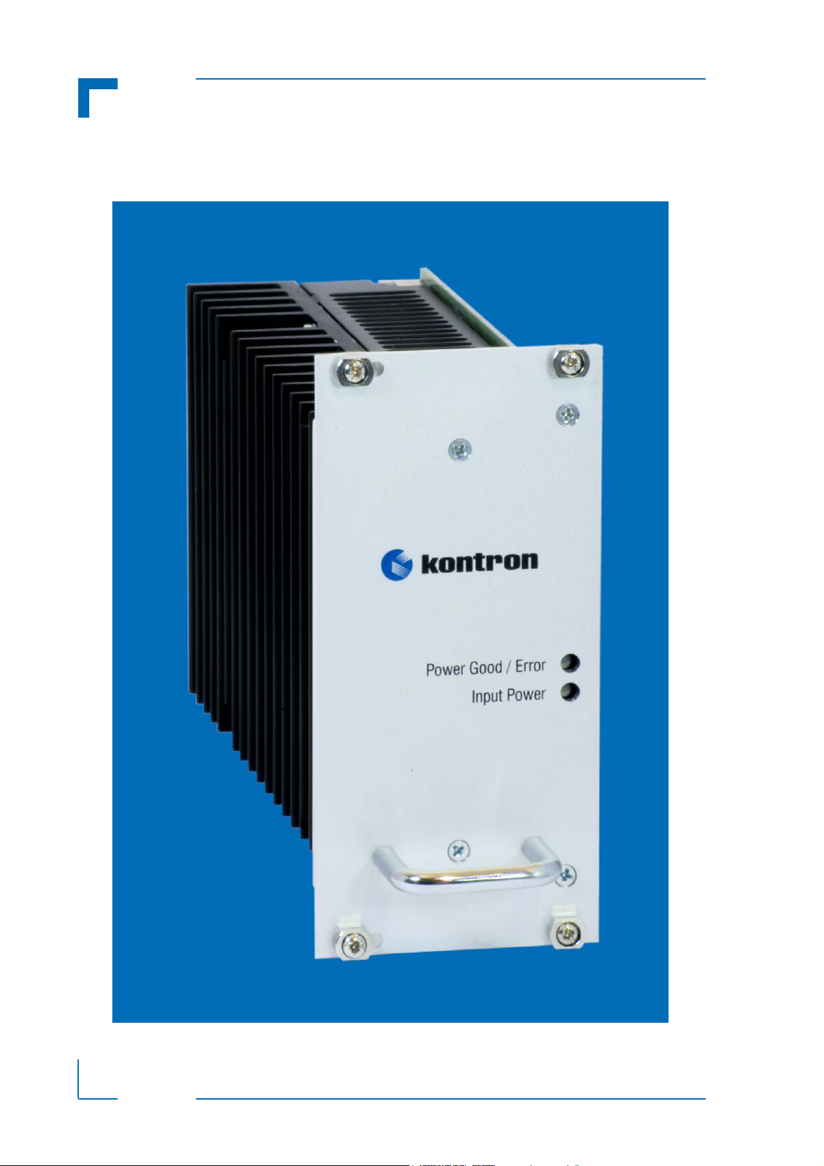
Figure 1: View of Power Supply Unit CP3-SVE-M100DC
Page 4
RID 24139 PD15, Rev.02
Page 5

CPCI Power Supply PD15: CP3-SVE-M100DC
24
168
slot right
slot left
(7.77)
12TE
slot right
slot left
60.62
Figure 2: Power Supply Dimensions
RID 24139 PD15, Rev.02
Page 5
Page 6

PD15: CP3-SVE-M100DC CPCI Power Supply
2.2 Power Supply Connectors
2.2.1 DIN M24/8 Power Supply Connector
Figure 3: Orientation of the DIN
M24/8 Power Supply Connector
The V1 ... V3 output voltages from
the power supply unit to the backplane are connected via a 32-pole
DIN 24/8 male power supply connector.
For the pinouts of the DIN M24/8
power supply connector please refer
to the following table.
Table 2: DIN M24/8 Connector Pinouts
PIN FUNCTION PIN FUNCTION
2 Vin + B.17 +3.3VL
5 Vin - B.18 +3.3VL
11 PE B.19 +12VL
A.13 NC B.20 NC
A.14 INH C.13 EN
A.15 NC C.14 DEG
A.16 0VF (5V sense -) C.15 FAL
A.17 +5VF (5V sense +) C.16 +3.3VL
A.18 +3.3VL C.17 +3.3VL
A.19 +12VL C.18 +3.3VL
A.20 NC C.19 +12VL
B.13 +3.3VL C.20 NC
B.14 +3.3VL 22 +5VL
Page 6
B.15 +3.3VL 25 OVL (GND)
B.16 +3.3VL
RID 24139 PD15, Rev.02
Page 7

CPCI Power Supply PD15: CP3-SVE-M100DC
2.3 Installation
Thanks to its plug-in compatibility this DIN M-type power supply unit allows for an easy installation, by which the power supply unit’s male DIN M24/8 power connector is inserted into the
backplane’s mating female connector without the need of any intermediate adaptation.
Warning!
To ensure a safe 5V operation of your equipment it is necessary that
on the backplane 5VL is connected to 5VF and 0VL to 0VF.
The maximum voltage compensation is +/- 0.15V per line.
Warning!
Handling of a hot power supply unit with bare hands can cause burns.
This power supply unit will get hot during operation. Under constant
maximum load the front panel temperature can be up to 15°C higher
than the ambient air temperature. In addition, the PSU heat sink and
metal housing may reach temperatures in excess of 85°C.
To replace a hot PSU, wear thermal protective gloves. Allow sufficient
cooling down of a hot PSU before further handling with bare hands.
Kontron will not accept liability for any injuries or damages, directly or
indirectly resulting from failure to comply with the above warning.
Note ...
If the main power input is switched off, the supply voltages will not go
to 0V instantly. It will take a couple of seconds until the capacitors are
discharged. If the voltage rises again before it has gone below a certain level, the circuits may enter a latch-up state where even a hard
RESET will not help any more. The system must be switched off for at
least 3 seconds before it may be switched on again. If problems still
occur, turn off the main power for 30 seconds before turning it on
again.
RID 24139 PD15, Rev.02
Page 7
Page 8

PD15: CP3-SVE-M100DC CPCI Power Supply
2.4 Electrical Specifications
Overview
INPUT Input Voltage Nominal 24V DC 36V DC 48V DC 72V DC 110V DC
Under Voltage Turn-on <16,8V DC
Under Voltage Turn-off <14,4V DC
(14,4V < Vin < 16,8V at t > 1 sec.)
Input Current @ Full Load 5.29A 3.43A 2.54A 1.67A 1.08A
OUTPUT Output 1 Output 2 Output 3
Output Voltage Nominal 3.3V DC 5V DC 12V DC
Output Current Nominal 12A
(14A for 20 ms)
10A
(12A for 20 ms)
4.8A
(10.5A for 20 ms)
Input
Input voltage ranges
14.4V..154V DC ( t
≤ 0.1 sec; EN50155 )
16.8..137.5V DC (constant)
Efficiency Typ. 85%
Input current limitation
Yes
Fuse 10AT (not user serviceable)
Enable / Inhibit Signal EN connected to Vin+: ON
EN open or connected to Vin-: OFF
Active Reverse Polarity Protection Max.160 V
Inrush Current Limitation Max. 20 A
Hold-up-time > 10 ms at full load
False Signal Open-collector output, active low
Output
Output Voltage 3.3 V / 5 V / 12 V
Temperature coefficient No derating over the specified temperature
range
Switch on / switch off performance No overshooting (soft-start)
Rise-delay time < 100ms
Start-up time ≤ 20ms
Minimum load No minimum load required
Page 8
RID 24139 PD15, Rev.02
Page 9

CPCI Power Supply PD15: CP3-SVE-M100DC
Initial Set Accuracy < 1.0 % (no load)
Short circuit Continuous short circuit proof
Ripple & Noise Output 1 and 2: < 50 mV pk-pk, 20 MHz
bandwidth
Output 3: < 240 mV pk-pk, 20 MHz
bandwidth
Max. Output Capacitance 500 uF x Iout nom
Temperature Coefficient < 0.02 %/°C
Regulation
Line regulation < 0.3% for 5V and 3.3V
Load regulation
Response time < 1ms at 25..75%
Protection and Control
Overvoltage protection 115% to 130% Vout
Overcurrent protection Output 1:
≤ 1.0 % at Iout 0 - 100%
Automatic repetition
At overload and short circuit the converter
switches off the output and tries to restart
after 2 sec.
Output 2:
At overload and short circuit the converter
switches off the output and tries to restart
after 2 sec.
Output 3:
At overload and short circuit the converter
switches off the output and tries to restart
after 2 sec.
Current limitation 14 .. 17A for 3.3V
12 .. 15A for 5V
10.5 .. 12 for 12V
Effective for all outputs, outputs short-circuit
proof
RID 24139 PD15, Rev.02
Page 9
Page 10

PD15: CP3-SVE-M100DC CPCI Power Supply
Overtemperature protection Shutdown at +97°C to 103°C baseplate
temperature with about 10°C hysteresis and
auto recovery.
Signal DEG (Derate) Open-collector output, low active
Signal FAL (False) Open-collector output, low active
Input EN (enable)
Input INH (inhibit)
Status indications LED’s for:
Operating Data
Temperature range: operating
Temperature range: storage
Warning!
Power is ON only with EN low (TTL)
Power always OFF with INH low (TTL)
Power Good / Error
all output voltages activated = green
voltage out of tolerance, over heating or
other error = red
Input Power
Vin > 16.8V DC = green
Vin < 16.8V DC = red
-40°C..+70°C with free convection
+85°C for 10 minutes
-40°C..+100°C
Adequate thermal cooling of the power supply must be ensured.
Therefore do not obstruct or hinder cooling air circulation or heat conduction within the power supply or surrounding equipment.
Failure to comply with this warning may result in damage to your
equipment.
Page 10
RID 24139 PD15, Rev.02
Page 11

CPCI Power Supply PD15: CP3-SVE-M100DC
Standards
Table 3: Standards Applicable to the CP3-SVE-M100DC
REQUIREMENT STANDARD SPECIFICATION COMMENT
ITE Safety Europe EN 60950-1 n.a. Safety Europe
Directive
2006/95/EC
Railway Safety EN 50155 Isolation (>10 MOhm)
Inp/Outp 1414Vdc
Inp/PE 1414Vdc
Outp/PE 710Vdc
Thermal
Operating
Climatic Test
Damp heat, cyclic
Random Vibration
Operating
Shock EN 50155 EN 61373 Class 1B Railway
EMC Emission EN 50155 EN 55011 Class B radiated and
EMC Immunity EN 50155 EN 50121-3-2 Railway
EN 50155 Class TX
-40 to +70°C
+85°C for 10min
EN 50155 IEC 60068-2-30
95% RH @ +25 to +55°C
2 cycles, each 24h
EN 50155 EN 61373 Class 1B Railway
conducted
Railway
Railway
Railway
Railway
RID 24139 PD15, Rev.02
Page 11
Page 12

PD15: CP3-SVE-M100DC CPCI Power Supply
X1/A18,
X1/2
X1/5
X1/11
U
PG/FALVIN
Output OVP
Overtemperature protection
Overload protection
Input Undervoltage protection
Acti ve
reverse
polarity
protection
Acti ve
inrus h
curren t
lim itation
Booster
X1/C 15
X1/C 14
X1/A14
X1/C 13
X1/ABC19
X1/B25
X1/A16
X1/A17
X1/B22
Step-Down
3V3
Digital
regu la ted
Step-Do wn
5V
Digital
regu la ted
B13-B18,
C16-C18
Block Diagram
Page 12
RID 24139 PD15, Rev.02
 Loading...