

Page 1

CPCI
Backplane
Manual
PRODUCT DOCUMENTATION
PD06
CP3-BP8-P47-RIO
Reference ID: 24229 PD06
Revision: 01
Issued: March 01, 2002
The product described in this manual
is in compliance with all applied CE
standards.
Page 2
PD06: CP3-BP8-P47-RIO CPCI Backplane
Revision History
CPCI BAckplane Manual:
Manual/Product Title:
Reference ID: 24229 PD06
Product Documentation:
CP3-BP8-P47-RIO
Rev.
Index
01 Initial Issue Mar. 01, 2002
Brief Description of Changes Date of Issue
Imprint
Copyright © 2002 PEP Modular Computers GmbH. All rights
reserved. This manual may not be copied, photocopied,
reproduced, translated or converted to any electronic or machinereadable form in whole or in part without prior written approval of
PEP Modular Computers GmbH.
DISCLAIMER:
PEP Modular Computers GmbH rejects any liability for the correctness
and completeness of this manual as well as its suitability for any particular purpose.
This manual was realized by: TPD/Engineering, PEP Modular Computers GmbH.
Page 2 © 2002 PEP Modular Computers GmbH RID 24229 PD06, Rev. 01
Page 3

CPCI Backplane PD06: CP3-BP8-P47-RIO
1. CPCI BackplaneIntroduction
The specific product description provided with this product documentation is part of the PEP’s
CPCI Backplane manual. For further information, in particular regarding general details as well
as safety and warranty statements, refer to the CPCI Backplane Manual, ID 24229.
2. CP3-BP8-P47-RIO Positronic-type Backplane
The main features of the 3U, 8-slot, 47-pin Positronic-type backplane CP3-BP8-P47-RIO,
which is designed for rear I/O applications, are described in the following table:
Table 1: Distinctive Features of Backplane CP3-BP8-P47-RIO
Feature Specification
Form Factor
Size
Number of Slots
Bus Resolution
Bus Frequency
Rear I/O Connectivity
Hot-Swap Capability
Power Supply Connector
Redundant Power Supply
Flexible Grounding Option
Fan Connector
MSD Connector
PS-ON Connector
3U
202.2*128.7 mm
8
32 bits: slots 1 to 8
33MHz: slots 1 to 8
P2 on slots 1 to 8
Yes
47-pin Positronic PCIH47
Optional
Yes
Yes
Yes
Yes (INH#)
Reset Function Connector
IPMB Extension Connector
System MON-CTRL Connector
RID 24229 PD06, Rev. 01 © 2002 PEP Modular Computers GmbH Page 3
Yes
Ye s (IPMB0)
Yes
Page 4
PD06: CP3-BP8-P47-RIO CPCI Backplane
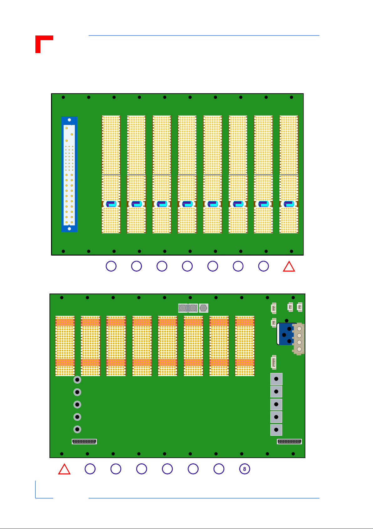
3. Board Layout
Figure 1: CP3-BP8-P47-RIO Board Layout (Front)
8
7
56
Figure 2: CP3-BP8-P47-RIO Board Layout (Reverse)
+5V +3V3VIO
JP5
GND
+5V
+3V3
-12V
+12V
JP12 JP11
4
3
2
JP21
JP22
JP19
GND
+5V
+3V3
-12V
+12V
1
JP17
JP16
JP3
1
2
3
4
56
7
Page 4 © 2002 PEP Modular Computers GmbH RID 24229 PD06, Rev. 01
Page 5

CPCI Backplane PD06: CP3-BP8-P47-RIO
4. Signalling Environment
4.1 V(I/O) Setting
The backplane provides a block of three high-current terminals (designated as V(I/O)) for connecting V(I/O) to either the +5V or +3.3V power supply . V(I/O) mu st be connected either to the
+5V or the +3.3V input power . It is the responsibility of the system integrator to ensure that the
required signalling voltage is implemented and that the backplane P1 connector coding corresponds to the implemented signalling voltage.
Warning!
Using both 3.3V and 5V boards within the same system may result in
damage to your equipment. Please note that the presence of only one
5V board determines a 5V signalling environ ment. The default setting
is 5V.
4.2 P1 Connector Coding for V(I/O)
The CompactPCI Specification foresees coding of the P1 connector to correspond to the signalling environment of the PCI bus. For this reason, only boards with universal or the corresponding coding can be physically inserted into the backplane. PEP’s factory default setting
for V(I/O) is +5V and male, 1567 code, brilliant blue coding keys are used.
Warning!
Using boards with an inadequate signalling voltage may result in damage to your equipment. Therefore, when changing the signalling environment from 5V to 3.3V or vice versa, it is mandatory that proper
coding keys are used (refer to chapter 3 of the CPCI Backplane Manual, ID 24229, for details).
RID 24229 PD06, Rev. 01 © 2002 PEP Modular Computers GmbH Page 5
Page 6

PD06: CP3-BP8-P47-RIO CPCI Backplane
5. Interfaces
5.1 Power Supply and Line Input
The V1 ... V4 output voltages from the power supply unit to the backplane are connected via a
47-contact, female, Positronic type power supply connector.
The main power supply input power is connected directly to pins 45, 46, and 47 of the power
supply connector. The is accomplished by means of a single, closed barrel pass-through contact for each pin via the reverse side of the backplane.
Figure 3: Orientation and Pinouts of CP3-P8-P47-RIO Positronic 47-pin Connector
47
46
45
Table 2: Pinouts of CP3-BP8-P47RIO 47-pin Connector
Pin Function
45 PE or GND
46 N or +DC
47 L or -DC
47
46
45
424344
394041
363738
333435
303132
272829
242526
212223
20
18
16
14
12
10
8
6
19
17
15
13
11
9
7
5
4
2
3
1
Page 6 © 2002 PEP Modular Computers GmbH RID 24229 PD06, Rev. 01
Page 7

CPCI Backplane PD06: CP3-BP8-P47-RIO
Table 3: Positronic 47-Pin Connector Pinout
PIN SIGNAL NAME DESCRIPTION PIN SIGNAL NAME DESCRIPTION
1 - 4 V1 V1 OUTPUT (+5V) 32 V2ADJ V2 ADJUST
5 - 12 RTN V1 and V2 RETURN 33 V2 SENSE V2 REMOTE SENSE
13 - 18 V2 V2 OUTPUT (+3.3V) 34 S RTN SENSE RETURN
19 RTN V3 RETURN 35 V1 SHARE V1 CURRENT SHARE
20 V3 V3 OUTPUT (+12V) 36 V3 SENSE V3 REMOTE S ENSE
21 V4 V4 OUTPUT (-12V) 37 IMPB_SCL IMPB SYS CLOCK
22 RTN SIGNAL RETURN 38 DEG# DEGRADE SIGNAL
23 RESERVED RESERVED 39 INH# INHIBIT
24 RTN V4 RETURN 40 IMPB_SDA IMPB SYS DATA
25 GA0 GA BIT 0 41 V2 SHARE V2 CURRENT SHARE
26 RESERVED RESERVED 42 FAL# FAIL SIGNAL
27 EN# ENABLE 43 IMPB_PWR IMPB POWER
28 GA1 GA BIT 1 44 V3 SHARE V3 CURRENT SHARE
29 NC NOT CONNECTED 45 CGND CHASSIS GROUND
30 V1SENSE V1 REMOTE SENSE 46 ACN / +DC IN AC INPUT NEUTRAL /
+DC INPUT
31 GA2 GA BIT 2 47 ACL / -DC IN AC INPUT LINE /
+DC INPUT
RID 24229 PD06, Rev. 01 © 2002 PEP Modular Computers GmbH Page 7
Page 8

PD06: CP3-BP8-P47-RIO CPCI Backplane
5.2 Fan Connectors
The backplane is equipped with two connectors for supplying power for fan(s) and for connecting a fan speed control device. JP21 (FAN1), a 3-contact, male connector, supplies +12V
for fan operation as well as the possibility to connect to a speed control device for regulating
air flow within the system sub-rack. JP22 (NTC1), a 2-contact ma le connector, provides a separate connection for a speed control device and is designed to be used in conjunction with
JP21.
For fans that have their own speed control or where no control is required, pins 1 and 2 of
JP21 can be used. For external speed control of fans, pins 2 and 3 of JP21 and pins 1 and 2
of JP22 are used. Pin 3 of JP21 and pin 2 of JP22 are connected internally on the board side
to each other.
External air flow regulation can be accomplished using a negative thermal coefficient (NTC)
device connected to JP22
Figure 4: Orientation and Pinouts of CP3-BP8-P47-RIO Connectors JP21 and JP22
JP21
JP22
3
2
1
2
1
Table 4: Pinout of CP3-BP8-P47-RIO
JP21 Connector
Pin Function
1GND
2 +12V
3NTC1
Table 5: Pinout of CP3-BP8-P47-RIO
JP22 Connector
Pin Function
1GND
2NTC1
Page 8 © 2002 PEP Modular Computers GmbH RID 24229 PD06, Rev. 01
Page 9

CPCI Backplane PD06: CP3-BP8-P47-RIO
5.3 MSD Connector JP3
One 4-contact female connector is installed on the backplane for the connection of mass storage devices (drives) to the +5V/+12V power supply of the bus.
Figure 5: Orientation and Pinout of the CP3-BP8-P47-RIO MSD Connector
Table 6: Pinout of CP3-BP8-P47RIO MSD JP3 Connector
1
Pin Function
2
3
1+12V
2GND
3GND
4
4+5V
5.4 Auxiliary Connectors and Signals
There are two, two-contact, male auxiliary connectors, JP16 and JP17 , available on this backplane.
JP16 and JP17 make the signal lines, PRST and INH# respectively, available for external
switches to either invoke a system reset or to switch the power supply on or off.
No other auxiliary signals are made available externally on the this backplane.
Figure 6: Orientation and Pinouts of CP3-BP8-P47-RIO Connectors JP16 and JP17
Table 7: Pinouts of CP3-BP8-P47-RIO
Connectors JP16 and JP17
JP17 JP16
2
1
RID 24229 PD06, Rev. 01 © 2002 PEP Modular Computers GmbH Page 9
Pin Function
1GND
JP16
2PRST
1GND
JP17
2INH#
Page 10

PD06: CP3-BP8-P47-RIO CPCI Backplane
5.5 System Management Connector JP19
One five-contact male system management bus (IPMB0) connector, JP19, is provided for
external interfacing to this bus. As this backplane has the RIO connector rP2 installed at the
system controller slot, pin 5, SMB_ALERT, is not connected on JP19.
Figure 7: Orientation and Pinout of the CP3-BP8-P47-RIO IMPB0 Connector JP19
Table 8: Pinout of CP3-BP8-P47RIO IMPB0 Connector JP19
Pin Function
5
1
1 IMPB0_SCL
2GND
3 IMPB0_SDA
4 IMPB0_PWR
5 not connected
Page 10 © 2002 PEP Modular Computers GmbH RID 24229 PD06, Rev. 01
Page 11

CPCI Backplane PD06: CP3-BP8-P47-RIO
5.6 System Monitor and Control Connectors JP11 and JP12
This backplane is provided with two connectors for system monitor and control signal interfacing to external devices. Both are 26-contact, male, double pin-row connectors, and have the
same signal pinout configuration. The system management bus (IPMB0), the power supply
monitor and control signals, and push button reset (PRST#) signal are all implemented on
these connectors.
Figure 8: Orientation and Pinout of the CP3-BP8-P47-RIO SMC Connectors JP11 and JP12
Table 9: Pinout of CP3-BP8-P47-RIO
SMC Connectors JP11 and JP12
Function
Pin
Pin Row A Pin Row B
JP11
b
a
113
1 IMPB0_SCL GND
2 IMPB0_SDA IMPB0_PWR
3N/C GND
4N/C GND
JP12
5N/C GND
6 INH# GND
7 FAL# DEG#
b
a
113
8PRST# GND
9 GND V1 SENSE (+5V)
10 V2 SENSE (+3.3V) SENSE RTN
11 V3 SENSE (+12V) GND
12 V1 SHARE (+5V) V2 SHARE (+3.3V)
13 V3 SHARE (+12V) GND
RID 24229 PD06, Rev. 01 © 2002 PEP Modular Computers GmbH Page 11
Page 12

PD06: CP3-BP8-P47-RIO CPCI Backplane
6. Optional System Configurations
6.1 Power Supply Options
The design of this backplane allows for several different power supply options:
1. The default configuration of a single compatible pluggable power supply.
2. Addition of compatible pluggable power supplies installed either to the left or right of the
backplane.
3. Use with an ATX-type power supply
4. Use with any external power sources compliant with the PICMG 2.11, R 1.0, CompactPCI
Power Interface Specification with regards to input voltage requirements.
Option 1 is the standard configuration which is delivered with a 47-contact female Positronic
type power supply connector.
Option 3 requires the installation of an ATX-type, 20-contact, female connector . If required, this
option must be specified when ordering as the board in the standard configuration is not populated with this connector.
To satisfy options 2 and 4 provisions have been made on the backplane for adding power terminals as required. Several different types of terminals may be installed. Bolt-type terminals
may be installed in all terminal positions. The square form set of terminal positions allow also
for the use of a variety of press-in terminal types. All terminals must be ordered separately.
Option 2 can be achieved through the use of special power supply adapter boards which can
be mounted either to the left or right of the backplane. These boards which accommodate pluggable power supplies are connected to the backplane terminals through the use of strapping
bars. In addition, the system monitor and control signals can be extended via JP11 or JP12 to
the power supply adapter boards using appropriate cabling. This configuration allows for additional power supplies to be added which satisfy system requirements such as redundancy,
power sharing, or simply increasing available power.
Option 4 allows for directly connecting DC power to the board via the optional terminals
whereby either terminal set may be used as needed.
6.2 System Addon Options
The CP3-BP8-P47-RIO backplane is designed to allow the installation of another backplane to
the right of it in a sub-rack and at the same time maintaining the slot raster . This feature makes
it possible to add additional slots to a single system using appropriate hardware or for accommodating two separate systems in one sub-rack.
Page 12 © 2002 PEP Modular Computers GmbH RID 24229 PD06, Rev. 01
 Loading...