

Page 1
Kontron CG1200 Carrier Grade Server
Document Revision 1.1
Page 2

Kontron CG1200 Carrier Grade Server Installation and Maintenance Guide i
» Table of Contents «
1
Introduction ...................................................................................... 1
1.1 About this Manual..................................................................................................................... 1
1.2 Manual Organization ................................................................................................................ 1
1.3 What Your Server Includes ....................................................................................................... 2
1.4 Product Accessories ................................................................................................................. 2
1.5 Additional Information and Software ......................................................................................... 3
2
Features .......................................................................................... 4
2.1 Server Components ................................................................................................................. 6
2.2 CG1200 Server Front Panel ..................................................................................................... 7
2.3 CG1200 Server Back Panel ...................................................................................................... 9
2.4 Front Panel Board .................................................................................................................. 10
2.5 LED/Switch Board .................................................................................................................. 10
2.6 Telco Alarm Module (TAM) Board ........................................................................................... 11
2.7 Hard Disk Drives .................................................................................................................... 11
2.8 Software and Hardware RAID ................................................................................................. 11
2.9 SD Flash Module .................................................................................................................... 11
2.10 Server Board (Baseboard) ...................................................................................................... 12
2.11 Riser Card Assembly .............................................................................................................. 13
2.12 Ethernet NIC Ports ................................................................................................................. 13
2.13 Remote Management Module 4 .............................................................................................. 13
2.14 I/O Module ............................................................................................................................. 14
2.15 Power Supply Subsystem ....................................................................................................... 14
2.16 System Cooling ...................................................................................................................... 14
2.17 Processors and Memory DIMMs ............................................................................................. 15
2.17.1 Processors ......................................................................................................... 15
2.17.2 Memory ............................................................................................................. 15
3
Standard Component Installations and Upgrades .......................... 16
3.1 Before You Begin ................................................................................................................... 16
3.1.1 Tools and Supplies Needed ..................................................................................... 16
3.1.2 System References ................................................................................................. 16
3.2 General Installation Procedures .............................................................................................. 16
3.2.1 Removing the Chassis Cover ................................................................................... 16
www.kontron.com
www.kontron.com
Page 3

Kontron CG1200 Carrier Grade Server Installation and Maintenance Guide ii
3.2.2 Re-installing the Chassis Cover ............................................................................... 17
3.2.3 Removing the Front Bezel ....................................................................................... 17
3.2.4 Re-Installing the Front Bezel .................................................................................... 18
3.2.5 Removing the Riser Card Assembly......................................................................... 18
3.2.6 Re-Installing the Riser Card Assembly ..................................................................... 19
3.3 Internal System Components Configuration and Installation Procedures ................................. 20
3.3.1 Configuring Memory DIMMs .................................................................................... 20
3.3.2 Supported Memory .................................................................................................. 20
3.3.3 Installing Memory DIMMs ........................................................................................ 21
3.3.4 Replacing or Removing Memory DIMMs .................................................................. 22
3.3.5 Adding or Replacing a Processor ............................................................................. 23
3.3.6 Installing the Heat Sink ............................................................................................ 30
3.3.7 Configuring Jumpers on the Server Board ............................................................... 31
4
Optional Component Installation Procedures ................................. 34
4.1 Before You Begin ................................................................................................................... 34
4.1.1 Tools and Supplies Needed ..................................................................................... 34
4.1.2 System References ................................................................................................. 34
4.1.3 Cable Routing Reference......................................................................................... 34
4.2 Installing or Replacing Hard Disk Drives ................................................................................. 37
4.2.1 Removing an HDD Carrier from the Chassis ............................................................ 37
4.2.2 Installing a Hard Drive in a Carrier ........................................................................... 38
4.3 Installing a Hardware RAID Controller .................................................................................... 40
4.3.1 Installing the ROC Module ....................................................................................... 40
4.3.2 Installing the SuperCap Module ............................................................................... 44
4.4 Adding or Replacing a Power Supply Module ......................................................................... 48
4.4.1 Adding a Second Power Supply Module .................................................................. 48
4.4.2 Replacing a Power Supply ....................................................................................... 49
4.5 Replacing a PCI Riser Card .................................................................................................... 49
4.5.1 Removing the Old Riser Card .................................................................................. 50
4.5.2 Installing a new Riser Card ...................................................................................... 50
4.6 Installing a PCI Add-in Card ................................................................................................... 50
4.7 Installing a Remote Management Module 4 ............................................................................ 52
4.8 Installing an I/O Module .......................................................................................................... 56
4.9 Installing an eUSB Flash Drive ............................................................................................... 58
4.10 Installing the Server into a Rack ............................................................................................. 59
4.10.1 Connecting the Power Cord ............................................................................... 59
www.kontron.com
www.kontron.com
Page 4

Kontron CG1200 Carrier Grade Server Installation and Maintenance Guide iii
4.10.2 Tools and Supplies Needed ............................................................................... 59
4.10.3 Equipment Rack Precautions ............................................................................. 60
5
Server Component Replacements ................................................. 61
5.1 Before You Begin ................................................................................................................... 61
5.1.1 System References ................................................................................................. 61
5.1.2 Cable Routing Reference......................................................................................... 61
5.2 Replacing Fans ...................................................................................................................... 61
5.3 Replacing the Front Panel Board ............................................................................................ 63
5.3.1 Removing the Old Front Panel Board ....................................................................... 65
5.3.2 Installing the New Front Panel Board ....................................................................... 66
5.4 Replacing the LED/Switch Board ............................................................................................ 67
5.4.1 Removing the Old LED/Switch Board ....................................................................... 67
5.4.2 Installing the New LED/Switch Board ....................................................................... 68
5.4.3 Replacing the LED/Switch Light Pipe Assembly ....................................................... 68
5.5 Replacing the Telco Alarms Module (TAM) ............................................................................. 68
5.5.1 Removing the Old Telco Alarms Module .................................................................. 69
5.5.2 Installing the New Telco Alarms Module................................................................... 70
5.6 Replacing the SAS Backplane Board ...................................................................................... 70
5.6.1 Removing the Old SAS Backplane Board ................................................................ 71
5.6.2 Installing the New SAS Backplane Board ................................................................. 73
5.7 Replacing the Power Distribution Board .................................................................................. 74
5.7.1 Removing the Old Power Distribution Board ............................................................ 74
5.7.2 Installing the New Power Distribution Board ............................................................. 77
5.8 Replacing the S2400EP4 Server Board .................................................................................. 79
5.8.1 Removing the Old Server Board from the Chassis ................................................... 79
5.8.2 Installing the New Server Board ............................................................................... 81
6
Server Utilities ............................................................................... 83
6.1 Using the BIOS Setup Utility ................................................................................................... 83
6.1.1 Using BIOS Setup ................................................................................................... 83
6.1.2 Starting Setup.......................................................................................................... 83
6.1.3 If You Cannot Access Setup .................................................................................... 83
6.1.4 Setup Menus ........................................................................................................... 83
6.2 Upgrading the BIOS ............................................................................................................... 85
6.2.1 Preparing for the Upgrade ....................................................................................... 85
6.2.2 Updating the System Firmware ................................................................................ 85
www.kontron.com
www.kontron.com
Page 5

Kontron CG1200 Carrier Grade Server Installation and Maintenance Guide iv
6.3 Restoring BIOS Default Settings ............................................................................................. 85
6.4 Clearing the Password ........................................................................................................... 86
6.5 BMC Force Update Procedure ................................................................................................ 86
6.6 ME Force Update Procedure .................................................................................................. 87
7
Troubleshooting ............................................................................. 88
7.1 Resetting the System ............................................................................................................. 88
7.2 Problems Following Initial System Installation ......................................................................... 88
7.2.1 First Steps Checklist ................................................................................................ 88
7.3 Hardware Diagnostic Testing .................................................................................................. 89
7.3.1 Verifying Proper Operation of Key System Lights ..................................................... 89
7.3.2 Confirming the Operating System Load ................................................................... 89
7.4 Specific Problems and Corrective Actions ............................................................................... 89
7.4.1 Power Light does not Light ...................................................................................... 89
7.4.2 No Characters Appear on Screen ............................................................................ 90
7.4.3 Characters are Distorted or Incorrect ....................................................................... 90
7.4.4 System Cooling Fans do not Rotate Properly ........................................................... 90
7.4.5 Cannot Connect to a Server .................................................................................... 91
7.4.6 Diagnostics Pass but the Connection Fails .............................................................. 91
7.4.7 The (NIC) Controller Stopped Working When an Add-in Adapter was Installed ......... 91
7.4.8 The Add-in Adapter Stopped Working without Apparent Cause ................................ 91
7.4.9 System Boots When Installing a PCI Card ............................................................... 92
7.4.10 Problems with Newly Installed Application Software ........................................... 92
7.4.11 Problems with Application Software that Ran Correctly Earlier ............................ 92
7.4.12 Devices are not Recognized under Device Manager (Windows*OS) ................... 92
7.4.13 Hard Drive(s) are not Recognized ...................................................................... 92
7.5 Light-Guided Diagnostics........................................................................................................ 93
7.5.1 5 Volt Stand-by LED ................................................................................................ 93
7.5.2 DIMM Fault LEDs .................................................................................................... 93
7.5.3 System ID LED, System Status LED, and POST Code Diagnostic LED ................... 93
7.5.4 POST Error Beep Codes ......................................................................................... 95
8
Warranty ........................................................................................ 97
9
Appendix A: Safety Information ..................................................... 98
9.1 Emissions Disclaimer ............................................................................................................. 98
9.2 Intended Uses ........................................................................................................................ 98
9.2.1 If AC power supplies are installed: ........................................................................... 98
www.kontron.com
www.kontron.com
Page 6

Kontron CG1200 Carrier Grade Server Installation and Maintenance Guide v
9.2.2 If DC power supplies are installed: ........................................................................... 99
9.2.3 DC Power Supply 48V Input Power Mating Connector ............................................. 99
9.2.4 DC Power Supply Earth Grounding Studs on Chassis ............................................ 100
9.2.5 Overcurrent protection ........................................................................................... 100
9.2.6 Temperature and Ventilation .................................................................................. 100
9.3 Safety Cautions .................................................................................................................... 100
9.3.1 Wichtige Sicherheitshinweise ................................................................................. 102
9.3.2 Consignes de sécurité ........................................................................................... 104
9.3.3 Instrucciones de seguridad importantes ................................................................. 105
10 Appendix B: Regulatory and Certification Information .................. 110
10.1 Product Regulatory Compliance ........................................................................................... 110
10.1.1 Product Safety Compliance .............................................................................. 110
10.1.2 Product EMC Compliance - Class A Compliance .............................................. 110
10.1.3 Certifications/Registrations/Declarations .......................................................... 110
10.2 Electromagnetic Compatibility Notices .................................................................................. 111
10.2.1 FCC (USA) ...................................................................................................... 111
10.2.2 Industry Canada (ICES-003) ............................................................................ 111
10.2.3 Europe (CE Declaration of Conformity)............................................................. 111
10.2.4 VCCI (Japan) ................................................................................................... 112
10.2.5 BSMI (Taiwan) ................................................................................................. 112
10.2.6 Regulated Specified Components .................................................................... 112
11 Appendix C: NEBS Considerations .............................................. 113
12 Appendix D: Getting Help ............................................................ 114
12.1 World Wide Web .................................................................................................................. 114
12.2 Telephone ............................................................................................................................ 114
12.3 Email .................................................................................................................................... 114
www.kontron.com
www.kontron.com
Page 7

Kontron CG1200 Carrier Grade Server Installation and Maintenance Guide 1
1 Introduction
1.1 About this Manual
Thank you for purchasing and using the Kontron CG1200 Carrier Grade Server.
This manual is for trained system technicians who are responsible for troubleshooting, upgrading, and
maintaining this server. This document provides a brief overview of the features of the system followed by
a list of accessories or other components you may need or want to purchase, instructions for how to add
or replace components in the CG1200 server, and troubleshooting information.
NOTE: Always be sure to search for CG1200 on the Support website at http://us.kontron.com/support/for
the latest version of this manual with possible updates since this version was published.
1.2 Manual Organization
Chapter 2 Features
provides a brief overview of the CG1200 server. In this chapter, you will find a list of the server board
features, chassis features, illustrations of the product, and product diagrams to help you identify
components and their locations
Chapter 3 Standard Component Installations and Upgrades
provides instructions for adding and replacing standard components such as processors and memory
DIMMs. Use this chapter for step-by-step instructions and diagrams for installing or replacing
components.
Chapter 4 Optional Component Installation Procedures
provides instructions for adding optional components such as PCI add-in cards, hardware RAID5
components, and an SD flash module. Use this chapter for step-by-step instructions and diagrams for
installing components.
Chapter 5 Server Component Replacements
provides instructions for replacing components such as boards and fans. Use this chapter for step-bystep instructions and diagrams for replacing components.
Chapter 6 Server Utilities
provides instructions for using the utilities that are shipped with the board or that may be required to
update the system. This includes how to navigate through the BIOS (Basic Input/Output System) setup
screens, how to perform a BIOS update, and how to reset the password or CMOS (Complementary Metal
Oxide Semiconductor). Information about the specific BIOS settings and screens is available in the Intel®
Server Board S2400EP4 Family Technical Product Specification.
Chapter 7 Troubleshooting
provides troubleshooting information. In this chapter, you will find BIOS error messages and POST
(Power-on Self Test) code messages. You will also find suggestions for performing troubleshooting
activities to identify the source of a problem.
Chapter 8 Warranty
provides the warranty information
Appendix A: Safety Information
provides the emissions disclaimer, power supply information, temperature and ventilation guidelines, and
safety cautions in multiple languages.
Appendix B: Regulatory and Certification Information
presents the regulatory and safety compliances and electromagnetic compatibility notices
1
Page 8

Kontron CG1200 Carrier Grade Server Installation and Maintenance Guide 2
Appendix D: Getting Help
1.3 What Your Server Includes
Your CG1200 server includes the following components:
• One 1U chassis
• One Intel® Server Board S2400EP4 with DDR3 memory slots (memory not included)
• Four removable hard drive carriers
• One DC or AC power subsystem: one hot-swappable power supply module and a power distribution
board. (The other power supply bay has a filler panel in it. For redundancy another separately
orderable power supply module must be added.)
• Five dual-rotor fan assemblies for cooling the processor(s), DIMM(s), PCI slot, and other internal
components in two cooling zones.
• A front panel board ,LED/switch board, telco alarms module (TAM) board, and PCIe riser assembly
(for one FH/FL card)
• Internal cables and connectors
See Chapter 3 for initial installation and configuration instructions.
1.4 Product Accessories
The following list shows the separately orderable components and optional accessories available for
inclusion in the initial order or to have as spares. Refer to the CG1200 Carrier Grade Server Configuration
Guide for a complete list of orderable spares and options. The Configuration Guide can be found on the
Kontron Support Website at http://us.kontron.com/support/ (search for CG1200, click on Product
Downloads, then Ordering Guide).
• LGA 2011 (socket R) support for Intel® Xeon® E5-2400 and E5-2400 v2 processors series
• Registered DDR3 Memory (RDIMM), LV-RDIMM, Unbuffered DDR3 Memory (UDIMM) with ECC and
Load Reduced DDR3 Memory (LR-DIMM)
• Up to four hot-swappable 2.5” SAS HDDs or SATA SSDs
• Hard disk drive carriers (four already shipped with the server)
• Optional Intel HW RAID on chip (ROC) or SW RAID IOC available.
• Optional I/O module
• Intel® Remote Management Module 4 (RMM4) or RMM4Lite options
• One front-access SD media flash module
• Internal flash storage supported (eUSB)
• Power cord
• AC or DC power supply module (650W) for redundancy
• Rack mount kits available for purchase directly from Kontron – see Configuration Guide
For information about the accessories, memory, processors, and ordering information, refer to the
CG1200 Carrier Grade Server Configuration Guide on http://us.kontron.com/support/(search for CG1200,
click on Product Downloads, then Ordering Guide).
For information about third-party hardware that has been tested and can be used with your system, refer
to the CG1200 Carrier Grade Server Tested Hardware and Operating System List (THOL) on
http://us.kontron.com/support/ (search for CG1200, click on Product Downloads, then Compatibility
Matrix).
2
Page 9

Kontron CG1200 Carrier Grade Server Installation and Maintenance Guide 3
1.5 Additional Information and Software
If you need more technical information or information about the accessories that can be used with this
CG1200 server, refer to the Technical Product Specifications (TPS) for the system and the server board.
The TPS documents are located on the Kontron support website at http://us.kontron.com/support. The
system TPS provides in-depth technical information about the server. The server board TPS provides indepth technical information about the server board, including BIOS settings and chipset information.
3
Page 10
Kontron CG1200 Carrier Grade Server Installation and Maintenance Guide 4
2 Features
This chapter briefly describes the main features of the Kontron CG1200 Carrier Grade Server. It provides
a diagram of the product, a list of the server features, and a diagram showing the location of important
components and connections on the server system.
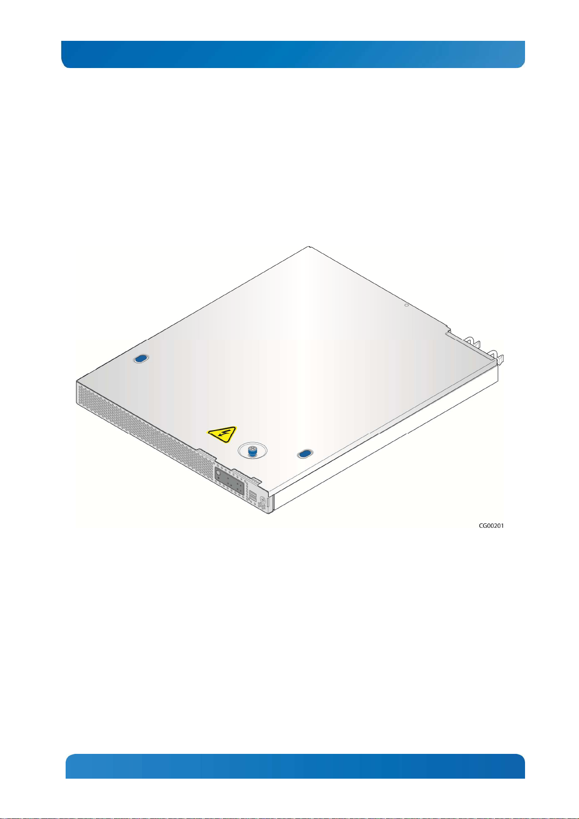
Figure 1 shows the CG1200 server.
Figure 1: Kontron CG1200 Carrier Grade Server
Table 1 summarizes the major features of the server system.
4
Page 11
Feature
Description
Peripheral Interfaces
Kontron CG1200 Carrier Grade Server Installation and Maintenance Guide 5
Table 1: CG1200 Server Features
External connections:
One DE-15 video VGA connector (rear)
One DB-15 TAM dry relay connector (rear)
Four RJ45 10/100/1000 Mbps network connections (rear)
Two USB 2.0 connectors (rear)
Two USB 2.0 connectors (front)
One RJ-45 serial connector (rear)
One dedicated management NIC port, (optional Intel® RMM4) or
personality module connector
Internal connections:
One internal USB header for embedded flash drives
One Intel® RAID C600 upgrade key connector with RKSAS54 preinstalled
One RMM4 connector for an optional Intel® Remote Management Module
4 module
Video Integrated graphics core with 2D hardware accelerator
LAN Four RJ-45 10/100/1000 Mbps connectors
Expansion Capabilities One PCIe x16 Gen 3 riser slot
Up to four 2.5-inch SAS HDD or SATA SDD hard drives
Hard Drive Options
Peripherals One SD media flash module (front panel access)
Front Panel Buttons
Front Panel LEDs
Power Supply
Onboard SAS SW RAID with Intel® ESRT2 RAID 0/1/10 or RSTe RAID
0/1/10
Intel® RAID on Chip (ROC) and I/O controller (IOC) support optional
Power on/off
System reset
Chassis ID
NMI
Power status
Chassis identification
System status
HDD activity/fault
NIC activity
Alarms (critical, major, minor, power)
Up to two 650W power supply modules (AC or DC)
PMBus 1.2 specification support
Auxiliary I/O power dongle
Fans
System Management Integrated BMC (iBMC) with advanced options
Five 40x56mm dual rotor fans
Redundant cooling
5
Page 12
Kontron CG1200 Carrier Grade Server Installation and Maintenance Guide 6
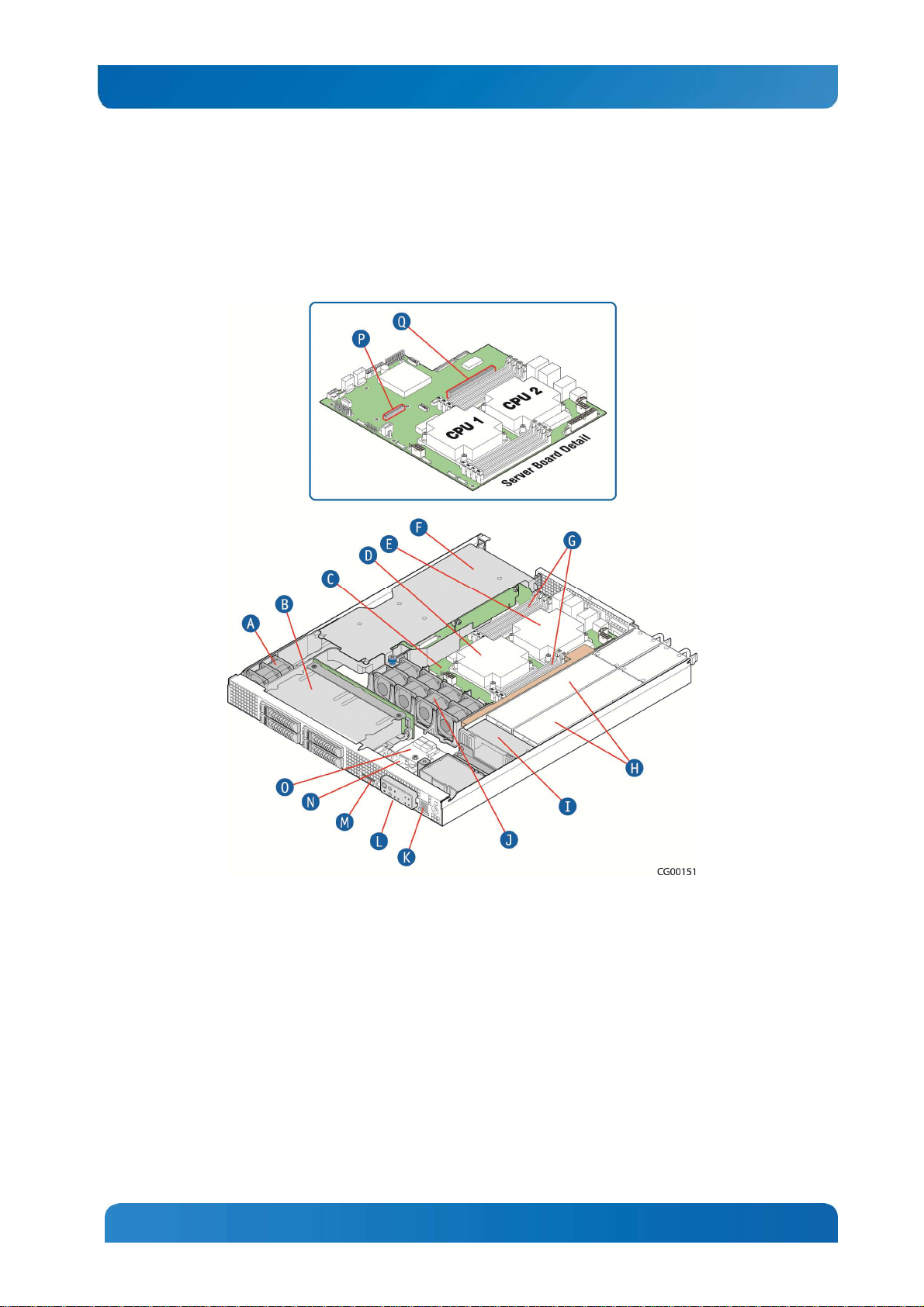
2.1 Server Components
Figure 2 shows the CG1200 server with the top cover removed to show the internal components.
Figure 2: CG1200 Server Components
6
Page 13
Kontron CG1200 Carrier Grade Server Installation and Maintenance Guide 7
Table 2: CG1200 Server Components
Item Description Item Description
A
B
C
D
E
F
G
H
I
PCI fan (one pair)
SAS hard drive bay
Intel® S2400EP4 Server Board
CPU 1
CPU 2
PCIe FH/FL riser card assembly
Eight DDR3 memory DIMM slots, two banks of
four DIMMs for each processor
Redundant, hot-swappable AC or DC power
supply modules
Power distribution board (PDB)
J
K
L
M
N
O
P
Q
CPU/memory fans (four pairs)
USB ports (two)
Front panel switches and indicators
SD media slot
Front panel board
Telco alarm module (TAM) board
RAID module connector
PCIe slot
2.2 CG1200 Server Front Panel
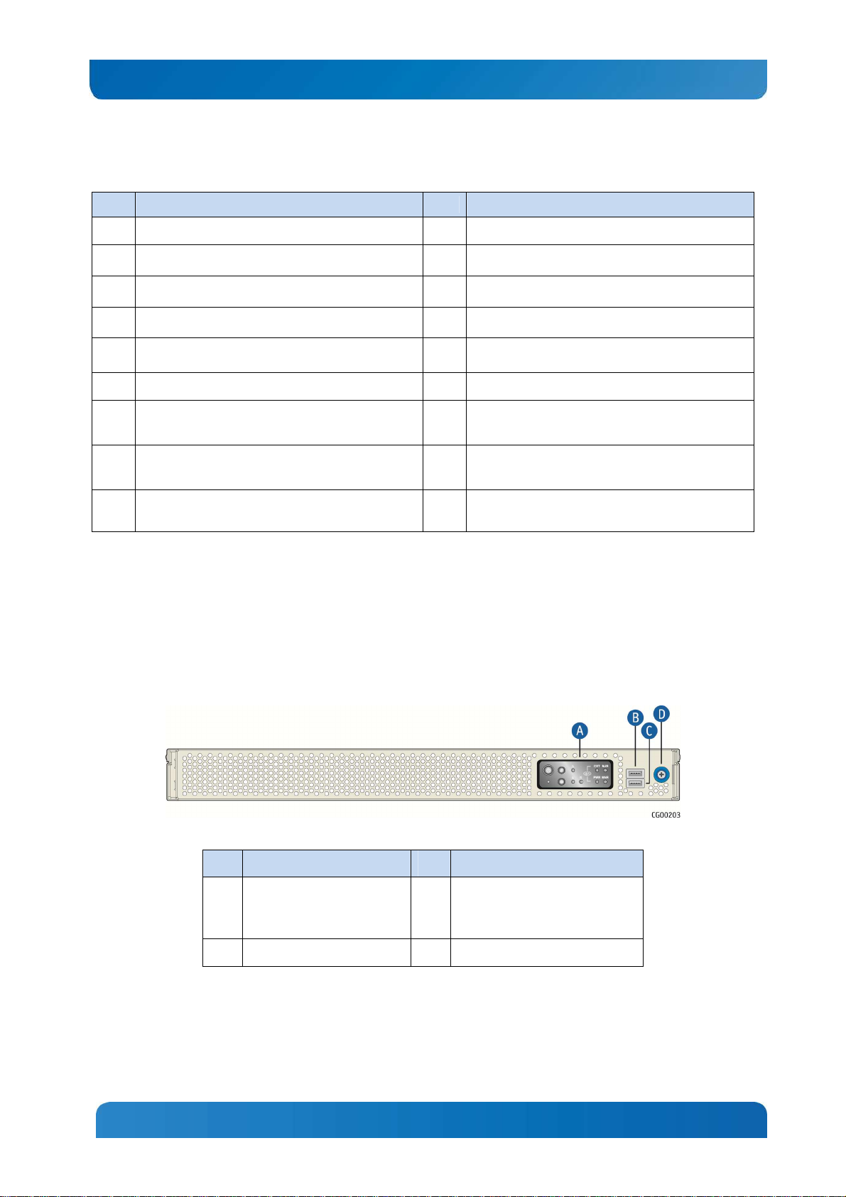
Figure 3 shows the front panel of the CG1200 server with the bezel installed.
Figure 3: CG1200 Server Front View (Bezel Installed)
Item Description Item Description
A
Front panel control buttons
and status indicator and
telco alarm LEDs
B
USB port
Figure 4 shows the front panel of the CG1200 server with the bezel removed.
7
C
USB port
D
Bezel captive screw
Page 14
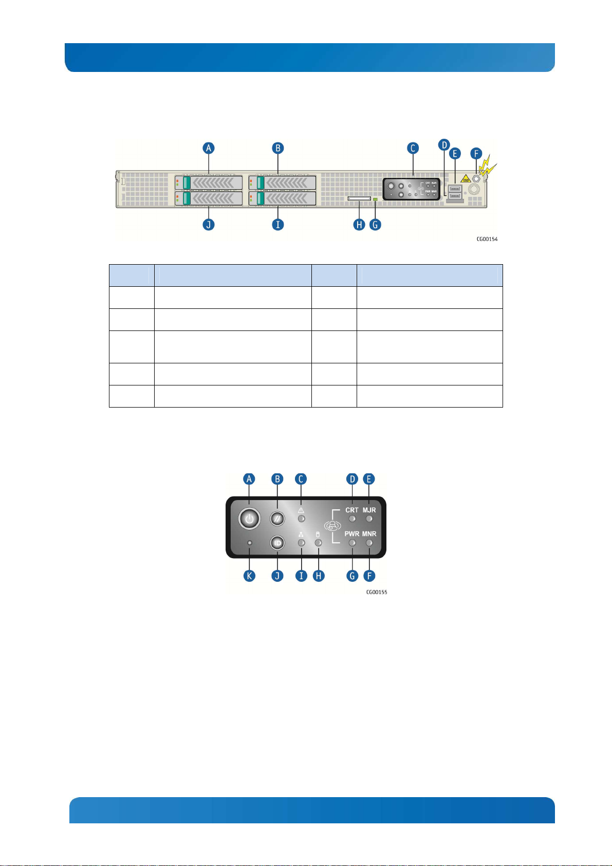
Kontron CG1200 Carrier Grade Server Installation and Maintenance Guide 8
Figure 4: CG1200 Server Front View (Bezel Removed)
Item Description Item Description
A
B
C
D
E
Hard disk drive slot 3
Hard disk drive slot 2
Mini-bezel control buttons, status
indicator and telco alarm LEDs
USB port
USB port
Figure 5 shows the CG1200 server control panel.
Figure 5: CG1200 Server Control Panel
F
G
H
I
J
ESD ground strap attachment
SD flash card LED
SD flash card slot
Hard disk drive slot 0
Hard disk drive slot 1
8
Page 15
Kontron CG1200 Carrier Grade Server Installation and Maintenance Guide 9
Item Description Item Description
A
B
C
D
E
F
† Critical and Major alarm indicators are bi-color LEDs that can be configured to be yellow or
red by means of an SDR TAM setting. Yellow is the default color.
Power button
System reset button
System status indicator LED
Critical alarm (amber or red†)
Major alarm (amber or red†)
Minor alarm (amber)
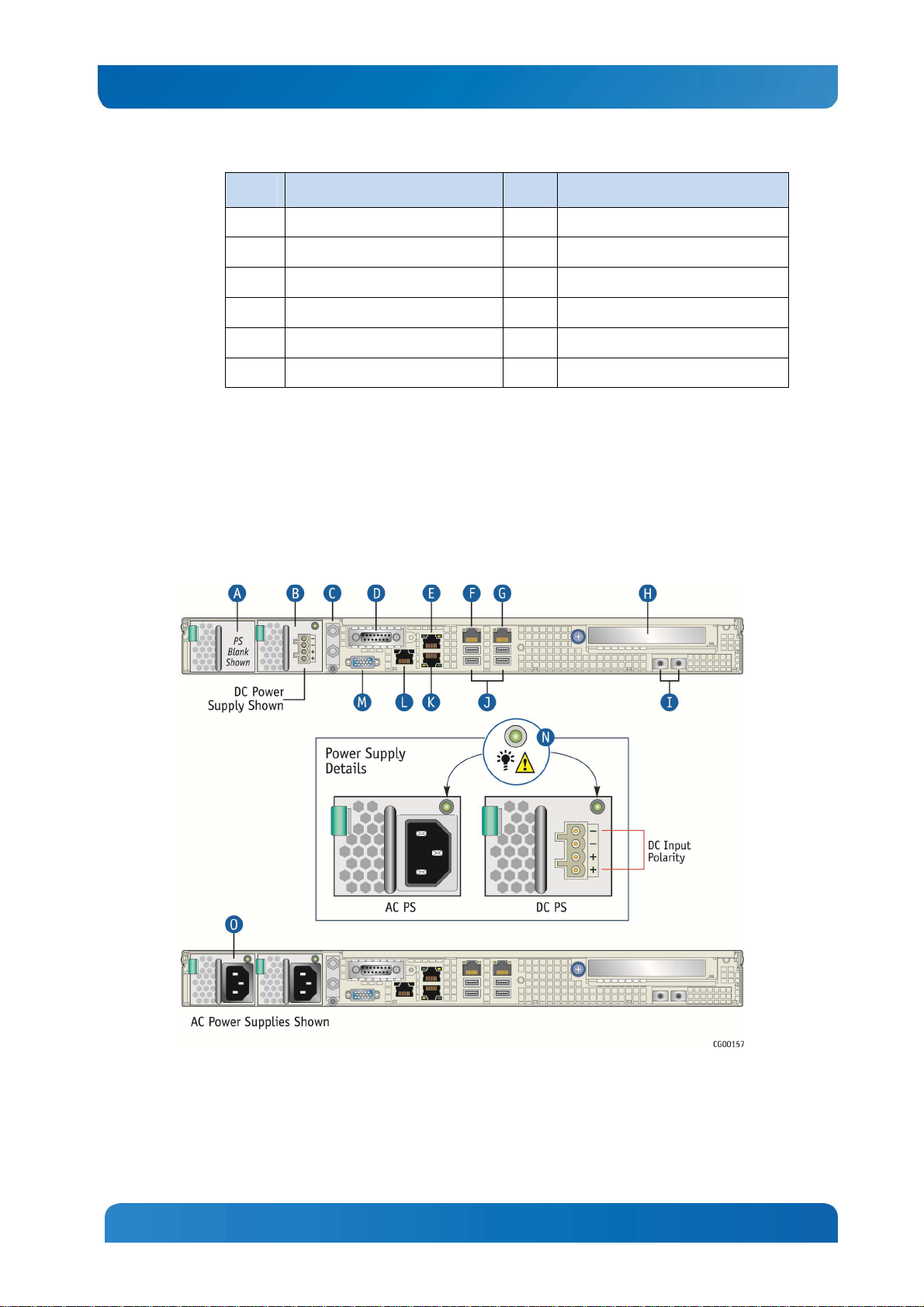
2.3 CG1200 Server Back Panel
Figure 6 shows the back panel of the CG1200 server.
Figure 6: CG1200 Server Rear View
G
H
I
J
K
Power alarm (amber)
HDD activity LED
NIC activity LED
Chassis ID button
NMI button
9
Page 16
Kontron CG1200 Carrier Grade Server Installation and Maintenance Guide 10
2. If RMM4 NIC is not used, a filler panel occupies this space
Item Description Item Description
A
B
C
D
E
F
G
H
NOTES:
1. In non-redundant configurations, power supply slot 2 must have a filler panel installed.
Optional power supply slot 2 (filler panel shown)1
Power supply slot 1 (shown with DC power supply
installed)
DC power grounding studs
Telco alarms connector
NIC port 1
NIC port 3
NIC port 4
PCIe slot
I
J
K
L
M
N
O
I/O module (filler panel shown)2
USB ports
NIC port 2
Serial port A
Video port
Power supply LEDs
Power supply 2 (shown with AC power supply
installed)
2.4 Front Panel Board
The front panel (FP) board is located behind the front bezel and in front of the fans. The FP board
provides the following feature set:
• Two USB ports: one to drive the USB ports on the front panel USB connector and one to drive the SD
flash module controller.
• Control circuitry for driving the NIC activity LED, the system status LED, the power LED, and the disk
activity LED, which are all located on the LED/switch board
• On-board LED that indicates USB flash drive activity
• System power state and status indicators -- power, reset, and NMI switches
NOTE: There may be features (for future use) in addition to those in this list.
2.5 LED/Switch Board
The LED/switch board provides input selection switches and LED status indicators for the server system.
The LED/switch board is connected to the FP board and receives status and alarm signals from it. The
LED/switch board has the following features:
• Connects the front panel board signals to the front panel. There are four switches and five LEDs. The
power status LED and the chassis ID LED are embedded in the switch and the other three LEDs are
on the control panel. (See Figure 5.)
• On board switches for power, reset, chassis ID, and NMI
• On board LEDs to indicate power status, chassis ID, system status, HDD activity/fault and NIC
activity
NOTE: For information about the telco alarm LEDs that are also on the front panel, see Section 7.5, LightGuided Diagnostics
10
Page 17
Kontron CG1200 Carrier Grade Server Installation and Maintenance Guide 11
2.6 Telco Alarm Module (TAM) Board
The CG1200 server Telco Alarms Module (TAM) board provides the connector interface and supporting
logic for the telco alarms function. The TAM board also provides an alarms function with fault relays and
access by cable to the fault relay contacts at the back of the system. A ribbon cable connects the TAM
board to the front panel board.
For detailed information about the telco alarms and fault relays, see the “Telco Alarms (TAM)” chapter in
the CG1200 Carrier Grade Server Technical Product Specification on the Kontron support website at
http://us.kontron.com/support.
2.7 Hard Disk Drives
The CG1200 Carrier Grade Server chassis supports up to four hard disk drives that are accessible from
the front of the chassis when the bezel is removed. The hard disk drives are mounted in removable drive
carriers that latch into the drive bay sub-assembly. Up to four 2.5-inch hot-swappable drives, either serial
attached SCSI (SAS) rotating hard drives or SATA solid state drives (SSDs), can be mounted in the drive
bay.
Each drives can consume up to 12W of power. Drives used in this server must be specified to run at a
maximum ambient temperature of 40°C.
NOTES:
1) SATA rotating HDDs are not recommended for use in this system because they are sensitive to
rotational vibration from system fan blades and other HDDs.
2) The CG1200 server does not support all SAS or SATA drive models. For a list of validated hard drive
manufacturers and hard drive types, refer to the Tested Hardware and Operating System List (THOL) on
the Kontron website at http://us.kontron.com/support/ (search for CG1200, click on Product Downloads,
then Compatibility Matrix).
2.8 Software and Hardware RAID
Software RAID 0/1/10 is provided for all four SAS drives or SATA SSDs. If additional levels of software
and/or HW RAID are needed, see the Configuration Guide for all orderable options.
Hardware RAID (Intel ROC) is available as a separately-orderable module and an additional separatelyorderable CG1200 RAID cable kit that provides the cables and brackets required for installation.
For more information about these options, refer to the Configuration Guide located on the support website
at http://us.kontron.com/support/, (Search for CG1200, click on Product Downloads, then Ordering
Guide).
2.9 SD Flash Module
There is one front-accessible USB SD flash module. For a list of validated SD cards to use with this
module, see the Tested Hardware and Operating System List (THOL) on the Kontron website at
http://us.kontron.com/support/ (search for CG1200, click on Product Downloads, and then Compatibility
Matrix).
11
Page 18
Kontron CG1200 Carrier Grade Server Installation and Maintenance Guide 12
2.10 Server Board (Baseboard)
The CG1200 server uses the Intel® S2400EP4 server board for the baseboard. The processors and
memory DIMMs are on the server board and support for several optional accessories, such a PCI riser
slot, the platform management subsystem, and RMM4or I/O module connectors.
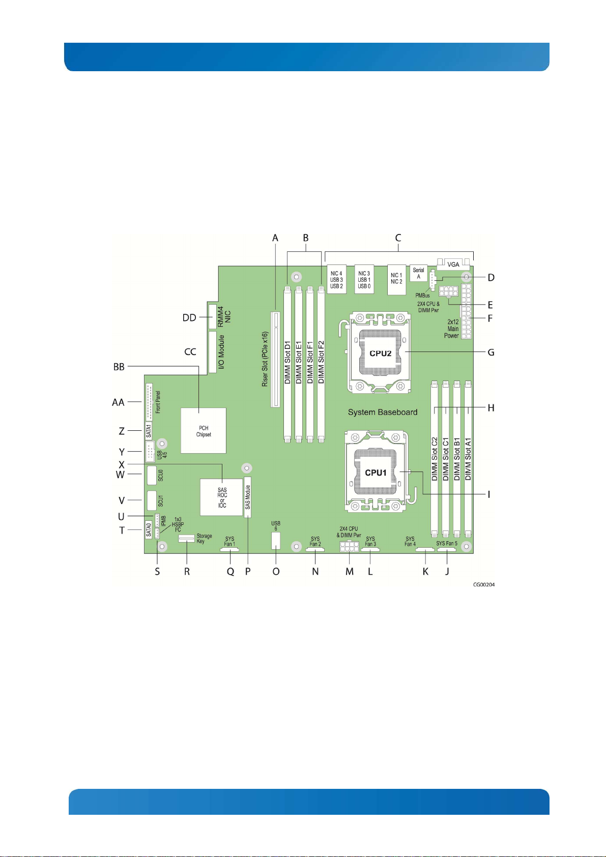
Figure 7 shows the key components and connectors on the S2400EP4 server board.
Figure 7: Baseboard Components and Connectors
12
Page 19
Kontron CG1200 Carrier Grade Server Installation and Maintenance Guide 13
Item Description Item Description
A PCIe x16 riser slot P SAS module
B CPU 2 DIMM slots Q Fan 1 power connector
C Rear panel I/O connectors R RKSAS4 storage key (pre-installed)
D PMBus connector S HSBP I2C connector
E CPU2 processor and DIMMs power
connector
F Baseboard main power connector U IPMB connector
G CPU processor socket V SAS HDD connector SCU1
H CPU1 DIMM slots W SAS HDD connector SCU0
I CPU1 processor socket X SAS RAID module (ROC or IOC)
J Fan 5 power connector Y Front panel USB connector
K Fan 4 power connector Z SATA 1 connector
L Fan 3 power connector AA Front panel connector
M CPU1 processor and DIMMs power
connector
N Fan 2 power connector CC I/O module connector
O Internal USB 6 connector DD RMM4 NIC or I/O module connector
T SATA 0 connector
BB Controller hub (PCH) chipset
2.11 Riser Card Assembly
The Intel® Server Board S2400EP4 has one riser slot capable of supporting a full-height, full-length PCIe
x16 riser card.
Once a PCI add-in card is installed and the riser card assembly is remounted in the chassis, the card is
accessible from the server back panel.
2.12 Ethernet NIC Ports
The S2400EP4 server board (baseboard) provides four network interface controller (NIC) RJ-45
connectors on the chassis back panel. Additional rear-accessible GbE NIC ports can be added to the
system by using a PCIe add-in card or installed as an I/O module.
2.13 Remote Management Module 4
RMM4 is a supported option on the S2400EP4 server board iBMC. To use this feature, a separatelyorderable RMM4 kit must be installed. Another option is an RMM4Lite kit that enables advanced features
in the iBMC without using a dedicated management NIC.
13
Page 20
Kontron CG1200 Carrier Grade Server Installation and Maintenance Guide 14
2.14 I/O Module
Space on the chassis floor with support standoffs is provided for adding an optional I/O module at the rear
of the server. An I/O module connector (and use of a smaller connector also used for RMM4 support) is
how the I/O module is connected to communicate with the server board.
2.15 Power Supply Subsystem
The power supply subsystem consists of up to two AC or DC hot-swappable power supply modules (two
needed for redundancy) and a power distribution board (PDB). The server comes with one power supply
module and a filler panel in the second power supply slot. The second redundant power supply is
separately-orderable.
The power supply module is rated for 650W output capability in full AC or DC input voltage range. The
minimum steady-state DC input voltage at which the equipment remains fully operational is -38 VDC. The
nominal operating voltage of the DC system is -48 VDC.
The server also includes an auxiliary power dongle from the power distribution board for use with
optional, additional cards.
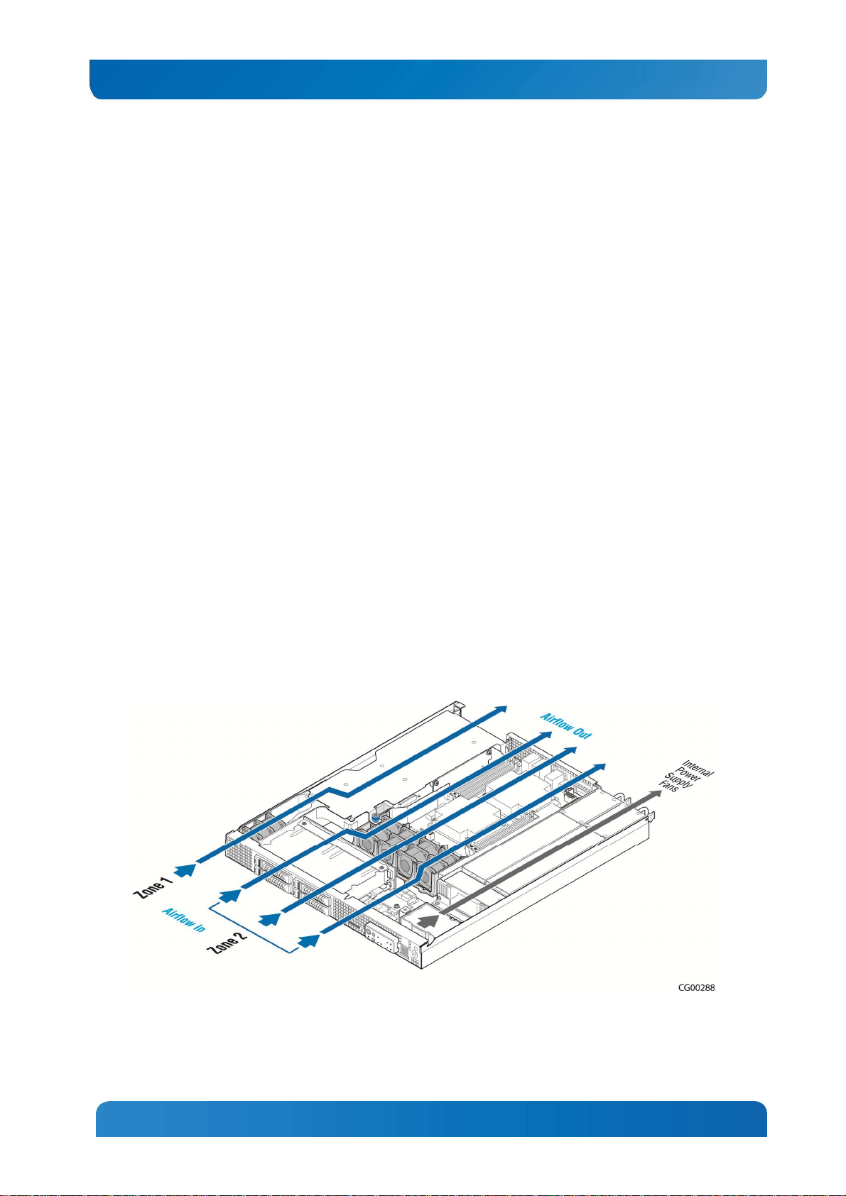
2.16 System Cooling
There are two cooling areas in the CG1200 server as illustrated in
Figure 8. All system components except the PCI riser card assembly and components under it are
cooled by a set of four CPU/DIMM dual rotor fans mounted near the front of the chassis behind the SAS
HDD bay. The PCI riser card assembly is cooled by a separate fan located in front of the riser assembly
on the left side of the chassis
Internal power supply fans cool the power distribution board (PDB) and power supply modules.
Figure 8: CG1200 Server Cooling Areas
The five-fan cooling subsystem is sized to provide cooling for:
14
Page 21
Kontron CG1200 Carrier Grade Server Installation and Maintenance Guide 15
• Up to two 70W server board processors
• Up to 256 GBytes of DDR3 memory
• Up to four hard disk drives
• One PCIe adapter
The cooling subsystem meets acoustic and thermal requirements at the lower fan speed settings. At the
higher fan speed settings, thermal requirements are met for the maximum ambient temperatures, but
acoustic requirements are not specified above 23 C+/-2 C.
2.17 Processors and Memory DIMMs
NOTE: To avoid integration difficulties and possible board damage, your server must meet the
requirements outlined below. For a list of qualified processors refer to the CG1200 Carrier Grade Server
Configuration Guide located on the support website at
click on Product Downloads, then Ordering Guide). For a list of qualified DIMMs refer to the Tested
Memory List at
http://us.kontron.com/support/
(search for CG1200, click on Product Downloads, then
Compatibility Matrix).
2.17.1 Processors
http://us.kontron.com/support/
(search for CG1200,
The S2400EP4server board accommodates FC-LGA 1356 Socket B2 support for two Intel® Xeon® E524XXL or E5-24XXL v2 processors. These processors can be ordered from Intel or an authorized
distributor using the Kontron part numbers listed in the CG1200 Carrier Grade Server Configuration
Guide.
2.17.2 Memory
The S2400EP4 server board supports 8 DIMM slots – one DIMM slots/channel for channels A,B,D,E and
two DIMM slots/channel for channels C and F. The server board supports registered DDR3 Memory
(RDIMM), Low-Voltage DDR3 memory (LVDDR3), load-reduced DIMMs (LRDIMMs), or unbuffered DDR3
memory (UDIMM) with data transfer rates of 800, 1066, 1333, and 1600 MT/s).
For detailed information about configuring memory on the server board, see the Intel® Server Board
S2400EP4 Family TPS.
15
Page 22
Kontron CG1200 Carrier Grade Server Installation and Maintenance Guide 16
3 Standard Component Installations and Upgrades
3.1 Before You Begin
Before working with your server product, pay close attention to the safety instructions provided in this
manual. See Appendix A, “Appendix A: Safety Information”
Warning: Electrostatic discharge (ESD) and ESD protection: ESD can damage disk drives, boards, and
other parts. We recommend that you perform all procedures in this chapter only at an ESD workstation. If
one is not available, provide some ESD protection by wearing an antistatic wrist strap attached to chassis
ground (any unpainted metal surface) on your server when handling parts.
3.1.1 Tools and Supplies Needed
• #1 and #2 Phillips (cross-point) screwdrivers (or interchangeable tip screwdriver with #1 and #2
Phillips bits)
• Personal grounding device such as an anti-static wrist strap and a grounded conductive pad
3.1.2 System References
All references to left, right, front, rear, top, and bottom assume that you are facing the front of the server,
as it would be positioned for normal operation.
3.2 General Installation Procedures
The following sections present general installation and removal procedures that are required before
removing or installing internal components that are not hot-swappable.
3.2.1 Removing the Chassis Cover
The CG1200 server must be operated with the top cover in place to ensure proper cooling. You will need
to remove the top cover to add or replace components inside the chassis that are not hot-swappable.
CAUTION: 5V standby power is present inside the chassis whenever the power supply module(s) are
connected to a power source. Before removing the top cover, always power down the server and unplug
all peripheral devices and the power cable.
A non-skid surface or a stop behind the server may be needed to prevent the server from sliding on your
work surface.
1. Observe the safety and ESD precautions in Appendix A, “Appendix A: Safety Information”.
2. Turn off all external devices connected to the server.
Turn off the server.
3. Disconnect the power cord(s).
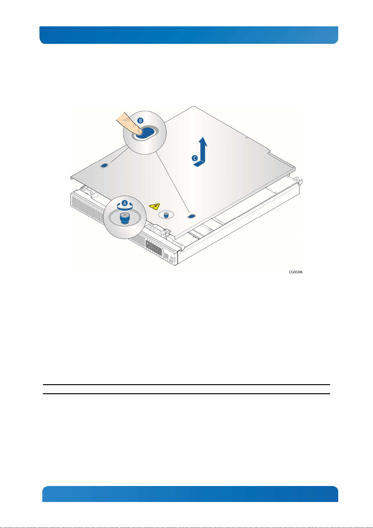
Figure 9 shows the top cover and how it is removed.
Removing the Cover
1. Loosen the captive thumb screw at the front of the cover (“A”).
2. Using the blue contact points on each side of the top cover (“B”), slide the cover backwards.
16
Page 23
Kontron CG1200 Carrier Grade Server Installation and Maintenance Guide 17
3. Lift the cover straight up to remove it from the chassis (“C”).
Figure 9: Removing the Cover
3.2.2 Re-installing the Chassis Cover
When you are finished working inside the chassis, you must put the cover back on before turning the
server back on. This step is required to ensure proper cooling.
Re-Installing the Cover
1. Starting from the rear of the chassis, place the cover down over the chassis with the side edges
outside the chassis walls.
2. Slide the cover forward until it is flush with the front panel.
3. Tighten the blue thumbscrew at the front of the top cover.
4. Reconnect any external devices and the power cord(s).
CAUTION: This unit must have the cover installed when it is running to ensure proper cooling.
3.2.3 Removing the Front Bezel
You need to remove the front bezel for tasks such as:
• Installing or removing hard disk drives
• Observing the individual hard disk drive activity/fault indicators on the drive carriers
• Replacing the control panel LED/switch board
• Accessing SD card slot
17
Page 24
Kontron CG1200 Carrier Grade Server Installation and Maintenance Guide 18
NOTE: The server does not have to be powered down just to remove the front bezel.
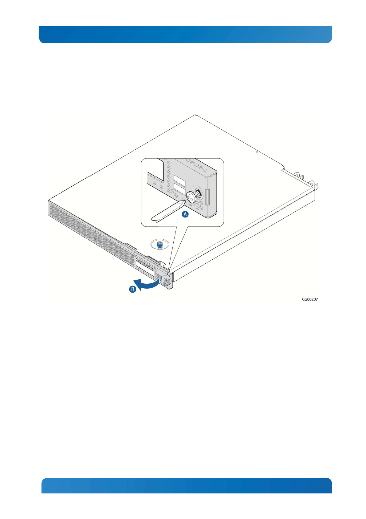
1. Loosen the captive bezel retention screw on the right side of the bezel (Figure 10, “A”).
2. Rotate the bezel to the left to free it from the pins on the front panel, (“B”) and remove it.
Figure 10: Removing the Front Bezel
3.2.4 Re-Installing the Front Bezel
1. Insert the tabs on the left side of the bezel into the slots on the front panel of the chassis.
2. Move the bezel toward the right and align it around the control panel and the USB ports.
3. Tighten the retention screw to secure the bezel. (Torque to 8lbf*in)
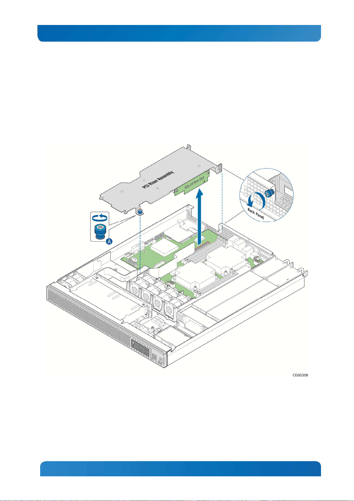
3.2.5 Removing the Riser Card Assembly
The riser card assembly has to be removed from the chassis to perform tasks such as:
• Replacing a riser card
• Installing or replacing a PCI add-in card
• Installing or replacing a hardware RAID controller
• Working with any components on the server board that are near the riser card assembly, such as the
CPU2 DIMMs, an I/O module, or an RMM4 card
• Replacing the server board
To remove the riser card assembly:
1. Power down the server and remove all external devices and the power cord(s)
18
Page 25
Kontron CG1200 Carrier Grade Server Installation and Maintenance Guide 19
2. Remove the chassis cover. For instructions, see Section 3.2.1 “Removing the Chassis Cover”.
3. Loosen the blue captive retention screw (
4. Figure 11, “A”) at the front of the riser assembly and the blue captive screw at the back panel of the
chassis.
5. Unhook the rear of the assembly from the guide pin on the back panel and lift the riser card assembly
out of the chassis.
Figure 11: Removing the Riser Card Assembly
3.2.6 Re-Installing the Riser Card Assembly
To re-install the riser card assembly:
1. Align the riser card with the card slot on the server board.
2. Position the riser front tab/captive screw over the stand-off on the chassis floor.
Make sure the tab at the rear of the assembly hooks over the guide pin on the chassis back panel.
19
Page 26
Kontron CG1200 Carrier Grade Server Installation and Maintenance Guide 20
3. Press down to mate the riser card with the slot on the server board.
NOTE: To avoid damaging the card edge, be sure that the card is lined up straight with the header, not on
an angle.
4. Tighten the blue captive retention screws at the front of the assembly and on the back panel.
5. Replace the chassis cover. For instructions see Section 3.2.2“Re-Installing the Cover”.
3.3 Internal System Components Configuration and Installation
Procedures
This section covers separately-orderable components that must be installed for your server to operate. It
also covers replacing these components and where relevant, such as with memory DIMMs, how to
configure them.
You install your separately-orderable DIMMs and processors on the Intel® Server Board S2400EP4,
which is the baseboard for this server.
NOTE: Be sure to read the information about the configuration rules and memory feature options in the
Intel® Server Board S2400EP4 Family Technical Product Specification e before you begin.
3.3.1 Configuring Memory DIMMs
The memory DIMM slots are located in two separate banks on the S2400EP4 server board. Detailed
information about the memory subsystem in the CG1200 server can be found in the Intel® Server Board
S2400EP4 Family Technical Product Specification located on the Kontron support website
http://us.kontron.com/support
(search for CG1200, click on Product Downloads, then Technical Info).
3.3.2 Supported Memory
The Intel® Server Board S2400EP4 supports eight DIMM slots with three memory channels for each
processor. There is one DIMM slot per channel for channels A, B, D, and E and two DIMM slots per
channel for channels C and F. Up to eight DIMMs can be used with dual-processor sockets giving a
maximum memory capacity of 256 GB.
The server board supports DDR3 800, DDR3 1066, DDR3 1333, and DDR3 1600 memory transfer rates.
Memory modules of mixed speed are supported by automatic selection of the highest common frequency
of all memory modules.
For detailed information about UDIMM, RDIMM and LRDIMM support guidelines, see Section 3.2.2.1,
“Supported Memory” in the Intel® Server Board S2400EP4 Family TPS.
Memory Map and Population Rules
The nomenclature for DIMM sockets implemented on the Intel® Server Board S2400EP4 is shown in
Table 4.
20
Page 27
Kontron CG1200 Carrier Grade Server Installation and Maintenance Guide 21
Processor Socket 1
Processor Socket 2
Table 3: Memory Map
(0) Channel A (1) Channel B
A1 B1 C1 C2 D1 E1 F1 F2
(2) Channel
C
(0) Channel D (1) Channel E
(2) Channel F
NOTE: Although mixed DIMM configurations may be functional, platform validations are performed only
on systems configured with identical DIMMs.
The S2400EP4 server board memory is implemented according to the following rules
• DIMMs are organized into physical slots on DDR3 memory channels that belong to processor
sockets.
• The memory channels from processor socket 1 are identified as Channel A, B, C.
The memory channels from processor socket 2 are identified as Channel E, F.
• Each memory slot on the server board is identified by channel and slot number within the channel.
For example, DIMM_A1 is the first slot on Channel A on processor 1; DIMM_D1 is the first DIMM
socket on Channel E on processor 2.
• The memory slots associated with a given processor are unavailable if the given processor socket is
not populated.
• A processor can be installed without populating the associated memory slots, provided the other
processor is installed with associated memory. In this case, the memory is shared by the processors.
However, the platform suffers performance degradation and latency because of the remote memory
accesses.
• Processor sockets are self-contained and autonomous. However, all memory subsystem support (i.e.,
Memory RAS, Error Management, etc.) in the BIOS setup is applied commonly across processor
sockets.
• The blue memory slots on the server board identify the first memory slot for each memory channel.
• For more information about population considerations, see Section 3.2.2.2 “Memory Slot Identification
and Population Rules” in the Intel® Server Board S2400EP4 Family TPS.
For information about what memory has been tested on the CG1200 server, see CG1200 Tested Memory
List on the Kontron website at http://us.kontron.com/support/ (Search for CG1200, click on Product
Downloads, then Tested Memory.)
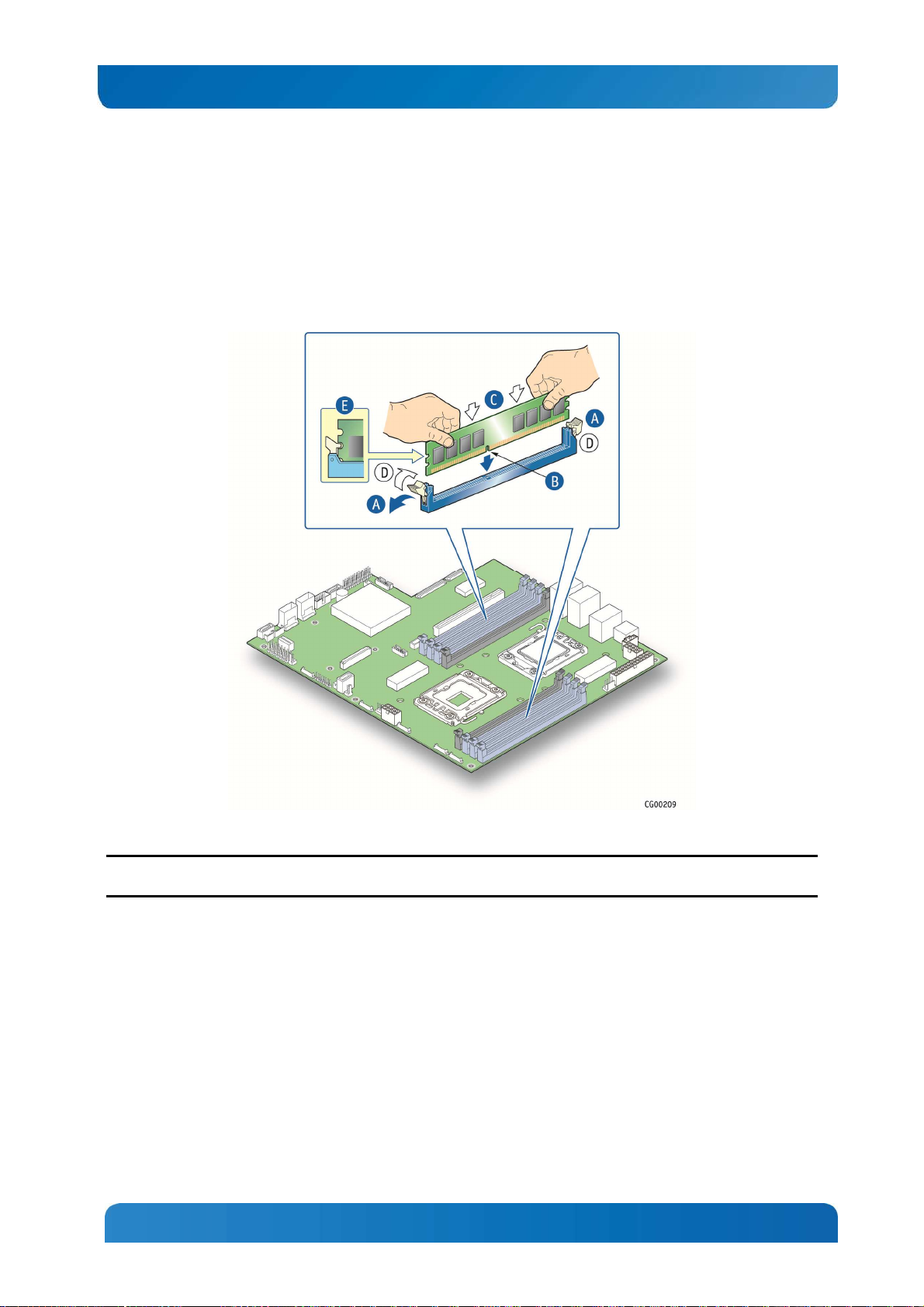
3.3.3 Installing Memory DIMMs
NOTE: To reduce the risk of electrostatic discharge (ESD) damage to the processor or the DIMM, be sure
to use a ground strap attached to the front panel (with the bezel removed).
To install DIMMs in the S2400EP4 server board slots:
1.
Power down the server and remove all peripheral devices and the power cord(s)
2.
Remove the chassis cover. For instructions, see Section 3.2.1 “Removing the Chassis Cover”.
3.
Note the location of the alignment notch. ( Figure 12, “B”)
4.
Insert the DIMM, making sure the connector edge of the DIMM aligns correctly with slot. (“E”)
21
Page 28
Kontron CG1200 Carrier Grade Server Installation and Maintenance Guide 22
5.
Using both hands, push down firmly and evenly on both sides of the DIMM until it snaps into place and
the levers close.(“C”)
IMPORTANT: Visually check that each latch is fully closed and correctly engaged with the notch on
the DIMM edge. (“D”)
6.
Replace the riser card assembly and the chassis cover if you have completed all work inside of the
server.
Figure 12: Memory DIMM Installation
3.3.4 Replacing or Removing Memory DIMMs
NOTE: To reduce the risk of electrostatic discharge (ESD) damage to the processor or the DIMM, use a
ground strap attached to the front panel (with the bezel removed).
To remove a DIMM from the S2400EP4 server board, follow these steps:
1.
Power down the server and remove all peripheral devices and the power cord(s)
2.
Remove the chassis cover. For instructions, see Section 3.2.1, “Removing the Cover”.
3.
Open the DIMM slot levers for the DIMM you want to remove. ()
4.
Using both hands, hold the DIMM by the edges and lift it up from the slot. Store the DIMM in an anti-
static package.
5.
If you are installing a replacement DIMM in this slot, return to Step 5 in “ Installing Memory DIMMs”.
Otherwise, replace the chassis cover if you have completed all work inside the server. See Section
3.2.2, “Re-installing the Chassis Cover” for instructions.
22
Page 29
Kontron CG1200 Carrier Grade Server Installation and Maintenance Guide 23
3.3.5 Adding or Replacing a Processor
CAUTION: The processor must be appropriate: You could damage the server board if you install a
processor that is inappropriate for your server. Refer to the Configuration Guide located on the support
web page
Ordering Guide) for a list of compatible processors for the CG1200 server.
Use the instructions provided below to add or replace a processor instead of using the instructions that
came with the processor.
Follow the instructions below to remove and then install a processor, referring to Figure 13 through Figure
22.
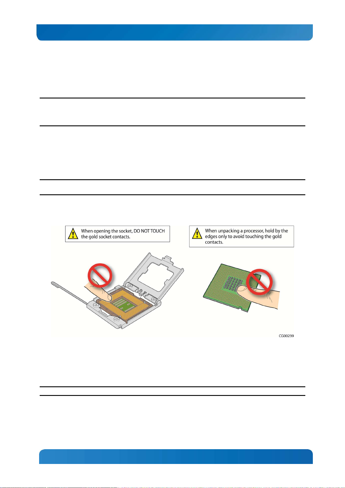
ESD and Processor Handling Precautions
NOTE: When handling the processors and sockets, to reduce the risk of electrostatic discharge (ESD)
damage to the processor use a ground strap attached to the front panel (with the bezel removed.)
http://us.kontron.com/support/
(search for CG1200, click on Product Downloads, and then
Figure 13: Cautions for Handling Processors
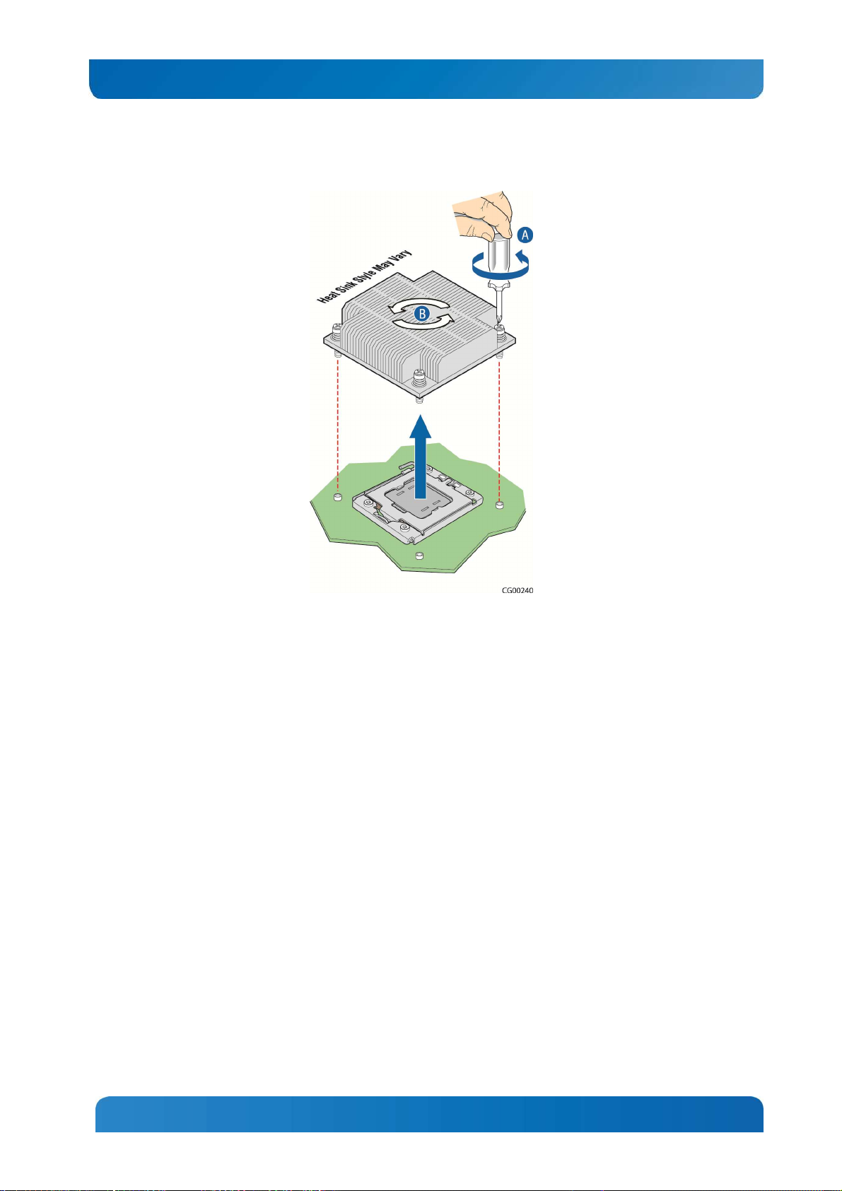
Removing a Processor
1. Loosen the four captive screws on the corners of the heat sink with a #2 Phillips screwdriver. (Figure
14, “A”)
2. Twist the heat sink slightly to break the seal between the heat sink and the processor. (“B”)
3. Lift the heat sink from the processor. If it does not pull up easily, twist the heat sink again.
NOTE: Do not force the heat sink from the processor. Doing so could damage the processor.
23
Page 30
Kontron CG1200 Carrier Grade Server Installation and Maintenance Guide 24
Figure 14: Removing the Heat Sink
4. Open the socket by pushing the lever handle down and away from the socket to release it. (Figure
16)
24
Page 31

Kontron CG1200 Carrier Grade Server Installation and Maintenance Guide 25
Figure 15: Using the Socket Lever
5. Lift the load plate up off the processor. (Figure 16)
25
Page 32

Kontron CG1200 Carrier Grade Server Installation and Maintenance Guide 26
Figure 16.Opening the Load Plate
6. Remove the protective cover in the socket (Figure 17 ) or the processor if you are replacing an
existing one.
26
Page 33

Kontron CG1200 Carrier Grade Server Installation and Maintenance Guide 27
Figure 17 Removing the Socket Protective Cover
Installing a New Processor
NOTE: Follow the ESD precautions covered in “ESD and Processor Handling Precautions”.
To install a processor, follow these instructions:
1. Take the processor out of its packaging and remove the protective shipping cover by grasping the
cover tab and pulling it away from the load plate. Store the protective cover for future use (
2. Figure 18).
Figure 18: Removing the Shipping Cover
27
Page 34

Kontron CG1200 Carrier Grade Server Installation and Maintenance Guide 28
CAUTION: The underside of the processor has components that may damage the socket pins if installed
improperly. The processor must align correctly with the socket opening before installation. Gently place
the processor onto the socket surface. Do not drop the processor into the socket!
3. Orient the processor with the socket so that the processor cutouts match the socket notches (
4. Figure 19).
5. Gently place the processor in the socket.
Figure 19: Installing the Processor in the Processor Socket
6. Carefully close the load plate (Figure 20).
7. Close the socket lever and ensure that the load plate tab engages under the socket lever when fully
closed.
28
Page 35

Kontron CG1200 Carrier Grade Server Installation and Maintenance Guide 29
Figure 20: Closing the Processor Load Plate
6. When the load plate comes down and the lever is latched, the socket cover pops off. Save it for future
use if the processor is removed from the socket (
7. Figure 21).
29
Page 36

Kontron CG1200 Carrier Grade Server Installation and Maintenance Guide 30
Figure 21: Closing the Socket Lever
3.3.6 Installing the Heat Sink
1. If this is a new heat sink (not the one you removed above), remove the protective film, if present, on
the Thermal Interface Material (TIM) located on the bottom of the heat sink (Figure 22, “A”).
2. Set the heat sink over the processor, lining up the four captive screws with the four posts surrounding
the processor. Align the heat sink fins to the front and back of the chassis for correct airflow (front to
back). Use caution and make sure that no cables are pinched beneath the heat sink.
3. Loosely screw in the captive screws on the heat sink corners and then tighten one, then the one
diagonally opposite, and so on until each one is firmly tightened (“B”).
CAUTION: the torque spec for these screws is 8 inch pounds. Be careful not to exceed it.
30
Page 37

Kontron CG1200 Carrier Grade Server Installation and Maintenance Guide 31
Figure 22: Installing a Heat Sink
3.3.7 Configuring Jumpers on the Server Board
The jumpers are located on the S2400EP4 server board. The system comes with the baseboard jumpers
configured in the default position for normal system operation. Only change the jumper position for
performing the desired recovery procedures outlined in this section. To work with the jumpers defined in
this section, you must first power down the chassis, remove the cover, remove riser card assembly as
described in Section 3.2 “General Installation Procedures”, and any optional modules or cables that might
be in the way. The other components on the server board can remain in place.
These 3-pin jumper blocks can be used to configure, protect, or recover specific features of the server
board. This section shows the jumper blocks available and what they do. For detailed information about
using these jumpers, see the Intel® Server Board S2400EP4 Family Technical Product Specification,
Chapter 9, “Reset and Recovery Jumpers”.
Pin 1 on each jumper block is identified by this symbol on the silkscreen: ▼
Figure 23 shows the jumper blocks.
31
Page 38

Kontron CG1200 Carrier Grade Server Installation and Maintenance Guide 32
Figure 23: Jumper Blocks (J1L4, J1L6, J1L7, J2L4, J2L5)
32
Page 39

Kontron CG1200 Carrier Grade Server Installation and Maintenance Guide 33
Table 4: Server Board Jumpers (J1L4, J1L6, J1L7, J2L4, J2L5)
Jumper Name Pins System Results
J1L4: BIOS
Default
J1L6: BIOS
Recovery
J1L7: BMC Force
Update
J2L4: ME Force
Update
J2L5: Password
Clear
1 - 2 These pins should be jumpered for normal system operation (Default)
2 - 3 If pins 2 – 3 are jumpered when AC power is unplugged, the CMOS
settings are cleared within five seconds.
Pins 2 - 3 should not be jumpered for normal operation.
1 - 2 These pins should be jumpered for normal system operation (Default)
2 - 3 The main system BIOS does not boot with pins 2 – 3 connected. The
system only boots from EFI-bootable recovery media with the recovery
BIOS image.
1 - 2 BMC Firmware Force Update Mode – Disabled (Default)
2 - 3 BMC Firmware Force Update Mode – Enabled
1 - 2 ME Firmware Force Update Mode – Disabled (Default)
2 - 3 ME Firmware Force Update Mode – Enabled
1 - 2 These pins should be jumpered for normal system operation (Default)
2 - 3 To clear administrator and user passwords, power on the system with
pins 2 – 3 connected. The administrator and user passwords clear in 5 –
10 seconds after power on.
Pins 2 – 3 should not be connected for normal system operation.
See Chapter 9, “Jumper Blocks” in the Intel® Server Board S400EP4 Family TPS on the Kontron Support
website for more information about the recovery features.
33
Page 40

Kontron CG1200 Carrier Grade Server Installation and Maintenance Guide 34
4 Optional Component Installation Procedures
This chapter covers separately-orderable components that you may want to add or replace in your
Kontron CG1200 Carrier Grade Server. Most of these components can be ordered as accessories from
Kontron and some are from third party vendors. For more information about what is available from
Kontron, see the CG1200 Carrier Grade Server Configuration Guide. For a list of qualified third party
vendors, see the Tested Hardware and Operating System List (THOL). The latest version of the
Configuration Guide is located on the Kontron support website at http://us.kontron.com/support/ (search
for CG1200, click on Product Downloads, then Ordering Guide). The latest version of the THOL is
located on the support website at http://us.kontron.com/support (search for CG1200, click on Product
Downloads, then Compatibility Matrix).
4.1 Before You Begin
Before working with your server product, pay close attention to the safety instructions provided in this
manual. See Appendix A: Safety Information”.
WARNING: Electrostatic discharge (ESD) and ESD protection: ESD can damage disk drives, boards, and
other parts. We recommend that you perform all procedures in this chapter only at an ESD workstation. If
one is not available, provide some ESD protection by wearing an antistatic wrist strap attached to chassis
ground (any unpainted metal surface) on your server when handling parts.
4.1.1 Tools and Supplies Needed
• #1 and #2 Phillips (cross-point) screwdrivers (or interchangeable tip screwdriver with #1 and #2
Phillips bits)
• Personal grounding device such as an anti-static wrist strap and a grounded conductive pad
4.1.2 System References
All references to left, right, front, top, and bottom assume that you are facing the front of the server, as it
would be positioned for normal operation.
4.1.3 Cable Routing Reference
It is important for cables to be connected correctly. See Figure 24 and Table 5 for cable routing and for
more detailed information, see the Kontron CG1200 Carrier Grade Server Technical Product
Specification.
34
Page 41

Kontron CG1200 Carrier Grade Server Installation and Maintenance Guide 35
Figure 24: Cable Routing
35
Page 42

Kontron CG1200 Carrier Grade Server Installation and Maintenance Guide 36
End #1 Connection
End #3 Connection
Table 5: System Cables
Interconnect #: Name:
1. Baseboard SSI Main
Power
2. CPU 1 and DIMM Power
3. CPU 2 and DIMM Power
4. SAS HDD Backplane
Board Power
5. SSI Front Panel Board
Power
6. Auxiliary I/O Power
Dongle
Baseboard SSI Power
Control Signal
7. PMBus Signal
8. HSBP I2C / HDD LED
End #2 Connection
End #1: Power Distribution
Board
End #2: Baseboard
End #1:Power Distribution
Board
End #2: Baseboard
End #1:Power Distribution
Board
End #2: Baseboard
End #1:Power Distribution
Board
End #2: SAS HDD Backplane
End #1:Power Distribution
Board
End #2: Front Panel Board
End #1:Power Distribution
Board
End #2: Cable to Cable
connector Baseboard
End #1: Power Distribution
Board Front Panel Board
End #2: Baseboard
End #1:SAS HDD Backplane
Board
End #2: Baseboard HSBP I2C
End #4 Connection
End #3: NA
End #4: NA
End #3: NA
End #4: NA
End #3: NA
End #4: NA
End #3: NA
End #4: NA
End #3: NA
End #4: NA
End #3: NA
End #4: NA
End #3: N/A
End #4: N/A
End #3: C-2-C (HDD-LED)
End #4:
9. Front Panel Signal
10. Front Panel Board USB
11. LED/Switch Board Power
and Signal
12. TAM Signal
End #1: Baseboard
End #2: Front Panel Board
End #1: Baseboard
End #2: Front Panel Board
End #1:Front Panel Board
End #2: LED/Switch Board
End #1:Front Panel Board
End #2: TAM Module
End #1:TAM Module
13. Alarms
End #2: System Rear Panel
Alarms Connector
14. Fan Power and Signal
(Fans 5A–5B)
15. Fan Power and Signal
(Fans 4A-4B)
End #1: Baseboard
End #2: Fan Pair (5A–5B)
End #1: Baseboard
End #2: Fan Pair (4A-4B)
36
End #3: NA
End #4: NA
End #3: NA
End #4: NA
End #3: NA
End #4: NA
End #3: NA
End #4: NA
End #3: NA
End #4: NA
End #3: NA
End #4: NA
End #3: NA
End #4: NA
Page 43

Kontron CG1200 Carrier Grade Server Installation and Maintenance Guide 37
End #1 Connection
End #3 Connection
Interconnect #: Name:
16. Fan Power and Signal
(Fans 3A-3B)
17. Fan Power and Signal
(Fans 2A-2B)
18. Fan Power and Signal
(Fans 1A-1B)
End #2 Connection
End #1:Baseboard
End #2: Fan Pair (3A-3B)
End #1:Baseboard
End #2: Fan Pair (2A-2B)
End #1:Baseboard
End #2: Fan Pair (1A-1B)
End #4 Connection
End #3: NA
End #4: NA
End #3: NA
End #4: NA
End #3: NA
End #4: NA
End #1:SAS HDD Backplane
19. Mini-SAS Signal
(HDD 0-1 /SCU0 )
Board
End #2: Baseboard SAS 0-3
End #3: N/A
End #4: NA
SCU0 Connector
4.2 Installing or Replacing Hard Disk Drives
Up to four hot-swappable SAS hard disk drives can be installed in your CG1200 server. The drives go
into carriers that connect to the SAS backplane board once the carriers with drives attached are inserted
back into the drive bay slots. The CG1200 server ships with four drive carriers.
CAUTION: If you install fewer than four hard disk drives, the unused drive slots must contain the empty
carriers with filler panels that ship with the server to maintain proper cooling.
The CG1200 server does not support all SAS HDD or SATA SDD disk drives. To see a list of validated
manufacturers and drive models, refer to the THOL. The latest version of the THOL is located on the
Kontron support website at
http://us.kontron.com/support/
. (Search for CG1200, click on Product Downloads,
then Compatibility Matrix).
NOTE: SATA rotating HDDs are not recommended for use in this system because they are sensitive to
rotational vibration from system fan blades and other HDDs.
You must remove the front bezel to add or replace a hard drive in one of the drive slots. It is not
necessary to remove the chassis cover or to power down the system. The hard drives are hot-swappable.
4.2.1 Removing an HDD Carrier from the Chassis
1. Remove the front bezel. For instructions, see 3.2.3, “Removing the Front Bezel”.
2. Select the drive slot where you want to install/replace the drive.
Drive slot 0 must be used first, then drive slot 1 and so on.
(Drive slot numbers are printed on the front panel to identify the drive slots.)
3. Remove the drive carrier from the drive bay by pressing the green button to open the lever that
engages the drive to the backplane (Figure 25, “A”).
4. Pull the drive carrier out of the chassis (“B”).
37
Page 44

Kontron CG1200 Carrier Grade Server Installation and Maintenance Guide 38
Figure 25: Removing the Drive Carrier
4.2.2 Installing a Hard Drive in a Carrier
1. If the drive carrier is empty (that is, if you are installing a drive in it for the first time), remove the black
plastic filler panel by unfastening the four screws that attach it to the carrier (Figure 26, “A”).
Set the screws aside for use with the new drive.
2. If a drive is already installed (that is, if you are replacing the drive), remove it by unfastening the four
screws that attach the drive to the drive carrier (Figure 26, “A”).
Set the screws aside for use with the new drive.
3. Lift the drive (or filler panel) out of the carrier (“B”).
38
Page 45

Kontron CG1200 Carrier Grade Server Installation and Maintenance Guide 39
Figure 26: Removing a Hard Drive
4. Install the new drive in the drive carrier (Figure 27, “A”) and secure the drive with the four screws that
come with the carrier (“B”).
Figure 27: Installing a Hard Drive
5. With the drive carrier locking lever fully open, push the hard drive carrier into the drive slot in the
chassis until it stops (Figure 28 “A”).
6. Press the locking lever until it snaps shut and secures the drive in the slot (“B”).
Replace the front bezel. For instructions, see 3.2.4, “
39
Page 46

Kontron CG1200 Carrier Grade Server Installation and Maintenance Guide 40
7. Re-Installing the Front Bezel”.
Figure 28: Inserting a New Hard Drive into the Chassis
4.3 Installing a Hardware RAID Controller
The CG1200 server supports the use of a RAID-on-chip (ROC) hardware RAID controller. This option is
separately orderable. The ROC module can be used with or without a SuperCap maintenance-free
backup module. If you are using the SuperCap module, the ROC module must be installed first, then the
SuperCap module.
Before you can install the ROC you must first remove the chassis cover, the front bezel, the PCIe fan
duct, and the riser card assembly.
4.3.1 Installing the ROC Module
1. Power down the server and remove all external devices and the power cord(s).
2. Remove the chassis cover. For instructions, see Section 3.2.1 “Removing the Chassis Cover”.
3. Remove the front bezel if you will be using the ESD ground attachment on the server for your anti-
static wrist strap grounding. For instructions, see section 3.2.3, “Removing the Front Bezel”.
4. Remove the riser card assembly. For instructions, see section 3.2.5, “Removing the Riser Card
Assembly”.
5. Remove the black plastic PCIe fan duct assembly:
NOTE: The fan does not need to be removed from the duct.
a. Disconnect the fan power/signal cable from the server board. (Figure 29, “A”)
40
Page 47

Kontron CG1200 Carrier Grade Server Installation and Maintenance Guide 41
b. Unfasten the screw at the back of the duct assembly (“B”) and slide the assembly up and
away from the chassis retention bracket (“C”).
Figure 29: Removing the PCIe Fan Duct
6. Disconnect the mini-SAS cable from both the SAS HDD backplane (“A”) and the SCU0 connector
on the server board (“B”). The ROC module uses a different cable that comes in the cable kit.
41
Page 48

Kontron CG1200 Carrier Grade Server Installation and Maintenance Guide 42
Figure 30: Removing the Mini-SAS Cable
7. Install the ROC module:
a. Firmly fasten the connector on the new SAS cable provided in the cable kit to the ROC
module. (Figure 31)
Figure 31: Connecting the SAS Cable to the ROC Module
42
Page 49

Kontron CG1200 Carrier Grade Server Installation and Maintenance Guide 43
b. Snap the four plastic standoffs from the RAID kit into the holes on the server board
(Figure 32, “B”).
c. Align the ROC module with the four standoffs and press down on the module to secure it
in place (“A”).
d. Install the four plastic compression pins through the holes on the ROC card and into the
standoffs. Press and tighten each pin in the standoffs to firmly secure the module to the
server board (“C”).
Figure 32: Installing the ROC Module on the Server Board
e. Firmly fasten the other end of the SAS cable to the connector on the SAS HDD
backplane.
Make sure the cable routes under the small air baffle to the right of the fan duct assembly
location.
43
Page 50

Kontron CG1200 Carrier Grade Server Installation and Maintenance Guide 44
Figure 33: Connecting the Mini-SAS Cable to the Backplane
If you are not installing a SuperCap module, then re-install the fan duct assembly, re-connect the fan
power cable to the server board, replace the riser card assembly, the front bezel, and the chassis cover,
and re-connect the power cord(s) and any external devices.
4.3.2 Installing the SuperCap Module
The SuperCap module is a flash-based backup module for hardware RAID. It comes in the optional
accessory kit, AXXRMBFU2, and is only supported when connected to the ROC module, RMS25CB040.
To install the SuperCap module:
44
Page 51

Kontron CG1200 Carrier Grade Server Installation and Maintenance Guide 45
1. Connect the SuperCap cable to the SuperCap module (Figure 34).
The module connector is keyed and the contacts face upwards.
Figure 34: Connecting the SuperCap Cable to the SuperCap Module
2. Unfasten the module retention screw from the mounting bracket on the chassis floor (Figure 35, “A”).
Move the power distribution board cables out of the way, if necessary.
Figure 35: Removing the Retention Screw from the SuperCap Bracket
45
Page 52

Kontron CG1200 Carrier Grade Server Installation and Maintenance Guide 46
3. Align the tabs on the bottom of the SuperCap module with the mating connectors on the bracket and
slide the module to the right to secure the SuperCap module to the bracket (Figure 36, “A”).
4. Fasten the SuperCap module to the bracket with the module retention screw (“B”) to ensure that the
module does not disengage from the bracket. (The retention screw will only tighten in place if the
module is properly installed in the bracket.)
Figure 36: Fastening the SuperCap Module to the Bracket
5. If the alarms cable from the TAM board is in the way, disconnect the cable and move it out of the way.
If the front panel power cable is in the way, disconnect the cable from the FPB and move it out of the
way.
(See 4.1.3, “ Cable Routing Reference” for the cable connector locations)
46
Page 53

Kontron CG1200 Carrier Grade Server Installation and Maintenance Guide 47
6. Route the SuperCap cable from the SuperCap module between the main fan assembly and the HDD
backplane, and then past the small U-shaped air baffle to the ROC module on the server board
(Figure 37).
Figure 37: Routing the SuperCap Cable to the ROC Module
7. Re-connect the front panel power cable and the TAM alarms cable if you moved them out of the way.
8. Re-install the PCIe fan duct assembly and connect the fan power cable to fan header 1 on the server
board.
9. Re-install the PCI riser card assembly and replace the front bezel and the chassis cover.
Re-connect any external devices and the power cord(s).
47
Page 54

Kontron CG1200 Carrier Grade Server Installation and Maintenance Guide 48
4.4 Adding or Replacing a Power Supply Module
Depending on which model you order, your server comes with one AC or one DC power supply module.
A second power supply provides redundancy.
NOTE: The CG1200 power supply units are hot-swappable, but you must unplug the power cord(s) from
the power source before adding them or removing them from the chassis.
4.4.1 Adding a Second Power Supply Module
Since the power supply modules are hot-swappable, no chassis components have to be removed to add
or replace a module. To add a second power supply module:
Figure 38: Adding a Power Supply
48
Page 55

Kontron CG1200 Carrier Grade Server Installation and Maintenance Guide 49
1. If you are installing a DC power supply, there are two threaded studs for chassis enclosure
grounding.
A 90°standard barrel, two-hole, compression terminal lug with 5/8-inch pitch suitable for a #14-10
AWG conductor must be used for proper safety grounding. A crimping tool may be needed to secure
the terminal lug to the grounding cable.
2. Connect the power cord to the power supply module.
Figure 39: DC Power Supply Grounding
4.4.2 Replacing a Power Supply
1. Disconnect the power cord from the existing power supply module and the power source.
2. Remove the old power supply module by pressing on the safety lock lever and using the handle,
pulling the module out of the chassis. See Figure 38.
3. Add the new power supply module by pressing and holding the safety lock lever (Figure 38, “C”) and
using the handle (“B”), sliding the new module into the chassis until it locks into place.
4. Plug the power cord into the new power supply and then connect it to the power source.
4.5 Replacing a PCI Riser Card
The server board PCIe slot supports a single slot riser for a PCIe X16 add-in card.
Figure 40 shows how a riser card is installed or removed from the sheet metal bracket.
49
Page 56

Kontron CG1200 Carrier Grade Server Installation and Maintenance Guide 50
Figure 40: Adding a Riser Card
CAUTION: When handling the riser card, observe normal safety and ESD precautions. (See Appendix A:
Safety Information” for more information.
4.5.1 Removing the Old Riser Card
To replace the riser card:
1. Power down the server and remove all external devices and the power cord(s)
2. Remove the chassis cover. For instructions, see Section 3.2.1“Removing the Chassis Cover”.
3. Remove the front bezel if you will use the ESD ground attachment with your anti-static wrist strap. For
instructions, see Section 3.2.3, “Removing the Front Bezel”.
4. Remove the riser card assembly from the chassis. For instructions, see Section 3.2.5, “Removing the
Riser Card Assembly“.
5. Unfasten the riser card from the bracket by loosening the two 6/32 screws shown in Figure 40.
6. If a PCI add-in adapter card is attached that you want to reuse, remove it and save it for use with the
new riser card.
4.5.2 Installing a new Riser Card
1. Fasten the new riser card to the bracket with the two 6/32 screws as shown in Figure 40.
Torque screws to 8 lbf*in.
At this point the riser card is ready for you to install an add-in card.
4.6 Installing a PCI Add-in Card
CAUTION: When handling a PCI add-in card, observe the normal safety and ESD precautions. See
Appendix A: Safety Information for more information.
To install a PCI add-in card, you must first remove the riser card assembly from the server chassis. See
Section 3.2.5, “Removing the Riser Card Assembly” for more information. If you haven’t done so already,
you must also install the riser card in the sheet metal cage.
50
Page 57

Kontron CG1200 Carrier Grade Server Installation and Maintenance Guide 51
1. Power down the server and remove all peripheral devices and the power cord(s)
2. Remove the chassis cover. For instructions, see Section 3.2.1“Removing the Chassis Cover”.
3. Remove the riser card assembly from the chassis. For instructions, see Section 3.2.5, “Removing the
Riser Card Assembly”.
4. Turn the riser card assembly upside down so it is resting on the top of the sheet metal cage.
If you are replacing a card in the slot, remove the existing card from the riser card socket.
If you are adding a PCI card, not replacing one, remove the blank filler panel from the rear bracket of
the riser card assembly by loosening the screw at the side of the bracket (Figure 41, “A”).
5. Attach the add-in card to the riser card connector (“B”).
Be sure that the add-in card edge connector is seated in the riser card connector correctly.
6. Fasten the add-in card to the riser card assembly bracket using the screw reserved from removing
the filler panel (“C”).
Figure 41: Installing a PCIe Add-In Card in the Riser Card Assembly
7. Re-install the riser card assembly into its slot on the baseboard (Figure 42, “A”).
8. Secure the riser card assembly by tightening the captive screws (“B” and “C”).
51
Page 58

Kontron CG1200 Carrier Grade Server Installation and Maintenance Guide 52
9. If this is the last task you are performing, re-install the riser card assembly and replace the front bezel
and the chassis cover.
Reconnect all the external devices and plug in the power cord(s).
Figure 42: Installing and Securing the Riser Card Assembly
4.7 Installing a Remote Management Module 4
The Remote Management Module (RMM) solution for the CG1200 server uses RMM4 in the iBMC on the
S2400EP4 server board. There are two options: the Intel® Remote Management Module 4 kit and the
Intel® Remote Management 4 Lite. This procedure shows how to install RMM4 Lite first and then full
RMM4.
The RMM4 kit includes a dedicated NIC module and a small key card to enable full functionality. (It also
contains other hardware and cables that are not used for installation in the CG1200 system.)
To install the RMM4 module you must first remove the chassis cover and the riser card assembly.
52
Page 59

Kontron CG1200 Carrier Grade Server Installation and Maintenance Guide 53
1. Power down the server and remove all external devices and the power cord(s).
2. Remove the chassis cover. For instructions, see Section 3.2.1, “Removing the Chassis Cover”.
3. Remove the front bezel if you will be using the ESD ground attachment for your anti-static wrist strap.
For instructions, see Section 3.2.3, “Removing the Front Bezel”.
4. Remove the riser card assembly. For instructions see Section 3.2.5, “Removing the Riser Card
Assembly”.
5. Unscrew the metal bracket behind the filler panel and remove it from the chassis (Figure 43, “B”).
Unscrew the metal filler panel from the rear of the bracket (“A”).
Figure 43: Removing the RMM4 Port Filler Panel
6. After removing the filler panel, reinstall the RMM4 bracket in the chassis (Figure 44, “A”).
7. Re-fasten the bracket to the chassis base with the screw that fastens the bracket to the chassis
on the left side and the screw for the standoff on the right side (“B”).
53
Page 60

Kontron CG1200 Carrier Grade Server Installation and Maintenance Guide 54
Figure 44: Re-installing the RMM4 Bracket
8. Install the RMM4 module into the slot in the bracket just installed (Figure 45, “A”). Make sure the
module fits within bracket clip (“B”).
9. Line up the edge connector on the module with the connector on the server board (“C”).
10. Fasten the module to the bracket using the screw removed previously (“D”).
At this point the installation is RMM4 lite.
54
Page 61

Kontron CG1200 Carrier Grade Server Installation and Maintenance Guide 55
Figure 45: Installing the RMM4 Board
11. To install full RMM4, install the small key card to the connector on the server board (Figure 46)
Figure 46: Installing the Full RMM4 Activation Key
55
Page 62

Kontron CG1200 Carrier Grade Server Installation and Maintenance Guide 56
12. If this is the last task you are performing, replace the riser card assembly and the chassis cover.
Reconnect all the external devices and plug in the power cord(s).
4.8 Installing an I/O Module
The CG1200 server supports the use of a separately purchased, optional I/O module, such as the Quad
GbE Ethernet Adapter listed in the THOL and Configuration Guide.
The I/O module is installed on the chassis floor at the rear of the chassis to the left of the server board. It
uses one or both of the white connectors on the edge of the server board. Before you can install an I/O
module, you must power down the system, remove the chassis cover and the PCI riser card assembly.
NOTE: I/O modules and RMM4 modules use the same rear panel slot and have overlapping real estate
on the chassis floor, so you can install one or the other, not both.
The Quad GbE adapter is used as the I/O module in this procedure.
1. Power down the server and remove all peripheral devices and the power cord(s).
2. Remove the chassis cover. For instructions, see Section 3.2.1, “Removing the Chassis Cover”.
3. Remove the front bezel to use the ESD ground attachment with your anti-static wrist strap. For
instructions, see Section 3.2.3, “Removing the Front Bezel”.
4. Remove the riser card assembly. For instructions, see Section 3.2.5, “Removing the Riser Card
Assembly”.
5. Remove the RMM4 module bracket by unfastening the two screws. See Figure 43, “Removing the
RMM4 Port Filler Panel” for the location of the bracket and the screws that fasten it to the chassis
floor.
6. Remove the top hex standoff on the chassis floor (Figure 47, “A”) and fasten it to the standoff where
the RMM4 bracket was installed (“B”).
56
Page 63

Kontron CG1200 Carrier Grade Server Installation and Maintenance Guide 57
Figure 47: Adjusting the I/O Module Standoffs
7. Install the I/O module into the rear of the chassis by lining up the three holes on the board with the
three standoffs and the module connector with the connector at the edge of the server board (Figure
48, “A” and “B”).
8. Secure the I/O module to the chassis by fastening the three screws that shipped with module into the
three standoffs. (“C”).
9. If this is the last task you are performing, replace the riser card assembly and the chassis cover.
Reconnect any external devices and plug in the power cord(s).
57
Page 64

Kontron CG1200 Carrier Grade Server Installation and Maintenance Guide 58
Figure 48: Installing the I/O Module
4.9 Installing an eUSB Flash Drive
A separately purchased, optional Embedded USB flash drive (eUSB) provides local USB flash memory
storage for various uses, such as system information, diagnostic partitions, and configuration data. The
eUSB is installed on the front panel board.
Before you can install an eUSB module, you must power down the system and remove the chassis cover.
(You may also have to disconnect some of the cables on the front panel board if they are in the way or
remove the front panel board from the chassis in order to do this installation in such a small crowded
area.)
1. Power down the server and disconnect any external devices and the power cord(s).
2. Remove the chassis cover. For instructions, see Section 3.2.1, “Removing the Chassis Cover”.
3. Remove the front bezel if you will be using the ESD ground attachment with your anti-static wrist
strap. For instructions, see Section 3.2.3, “Removing the Front Bezel”.
4. Locate the standoff and connector on the front panel board, to the right of the SD flash module
(Figure 49).
5. Install the eUSB module onto the front panel board by plugging the USB connector on the eUSB
module onto the USB header on the FPB (“A”) and fastening the module to the metal hex standoff on
the FPB (“B”).
6. If this is the last task you are performing, re-install the front bezel and the chassis cover. Reconnect
all external devices and the power cord(s).
58
Page 65

Kontron CG1200 Carrier Grade Server Installation and Maintenance Guide 59
Figure 49: Installing an eUSB Flash Module on the Front Panel Board
4.10 Installing the Server into a Rack
Several different rack mounting kits are available, depending on whether you need 2-post or 4-post
mounting and whether you need 19-inch or 23-inch rack widths. Also available are a basic slide rail kit
and a rail enabling kit. For detailed information about the rack mounting kits and how to order them, see
the CG1200 Carrier Grade Server Configuration Guide. The latest version of the Configuration Guide is
located on the Kontron support website at
Product Downloads, then Ordering Guide).
NOTE: This equipment should be installed and serviced in a restricted access area by trained technical
personnel. The knurled thumbscrew must be tightened with a #2 Philips head screwdriver after
installation of the top cover.
Installation instructions are included in each of the rack mounting kits.
4.10.1 Connecting the Power Cord
NOTE: When using a rack, wait to install the power cord(s) until after the server is in the rack.
4.10.2 Tools and Supplies Needed
• #1 and #2 Phillips (cross-point) screwdrivers (or interchangeable tip screwdriver with #1 and #2
Phillips bits)
http://us.kontron.com/support/
(search for CG1200, click on
59
Page 66

Kontron CG1200 Carrier Grade Server Installation and Maintenance Guide 60
• Personal grounding device such as an anti-static wrist strap and a grounded conductive pad
4.10.3 Equipment Rack Precautions
CAUTION: ANCHOR THE EQUIPMENT RACK — The equipment rack must be anchored to an
unmovable support to prevent it from falling over when one or more servers are extended in front of it on
slide assemblies. The equipment rack must be installed according to the manufacturer’s instructions. You
must also consider the weight of any other device installed in the rack.
Mains power disconnect — The power cord(s) is considered the mains disconnect for the server and
must be readily accessible when installed. If the individual server power cord(s) will not be readily
accessible for disconnection then you are responsible for installing a power disconnect for the entire rack
unit. This main disconnect must be readily accessible, and it must be labeled as controlling power to the
entire rack, not just to the server(s). To remove all power, two power cords must be removed.
Grounding the rack installation — To avoid the potential for an electrical shock hazard, for AC power
you must include a third wire safety ground conductor with the rack installation. For DC power the two
studs for chassis enclosure grounding must be used for proper safety grounding. See “E” in Figure 6 for
the location of the ground studs. With AC power, if the server power cord is plugged into an outlet that is
part of the rack, then you must provide proper grounding for the rack itself. If the server power cord is
plugged into a wall outlet, the safety ground conductor in the power cord provides proper grounding only
for the server. You must provide additional, proper grounding for the rack and other devices installed in it.
AC overcurrent protection — When AC power is used, the server is designed for a line voltage source
with up to 15 amperes of overcurrent protection per cord feed. If the power system for the equipment rack
is installed on a branch circuit with more than 15 amperes of protection, you must provide supplemental
protection for the server. The overall current rating of a server configured with two power supplies is less
than 6 amperes.
CAUTION: Temperature — The operating temperature of the server, when installed in an equipment rack,
must not go below 5°C (41°F) or rise above 40°C (104°F) ). Extreme fluctuations in temperature can
cause a variety of problems in your server.
60
Page 67

Kontron CG1200 Carrier Grade Server Installation and Maintenance Guide 61
5 Server Component Replacements
This chapter covers separately-orderable replacement spare components that you may need to replace in
your Kontron CG1200 Carrier Grade Server if they fail. For information about what is available from
Kontron, see the CG1200 Carrier Grade Server Configuration Guide. The latest version of the
Configuration Guide is located on the Kontron support website at http://us.kontron.com/support/ (search
for CG1200, click on Product Downloads, then Ordering Guide).
5.1 Before You Begin
Before working with your server product, pay close attention to the safety instructions provided in this
manual. See Appendix A: Safety Information.
WARNING: Electrostatic discharge (ESD) and ESD protection: ESD can damage disk drives, boards, and
other parts. We recommend that you perform all procedures in this chapter only at an ESD workstation. If
one is not available, provide some ESD protection by wearing an anti-static wrist strap attached to
chassis ground (any unpainted metal surface) on your server when handling parts.
5.1.1 System References
All references to left, right, front, top, and bottom assume that you are facing the front of the server, as it
would be positioned for normal operation.
5.1.2 Cable Routing Reference
It is important for cables to be connected correctly. See Figure 24 and
Table 5 for cable routing and for more detailed information, see the Kontron CG1200 Carrier Grade
Server Technical Product Specification.
5.2 Replacing Fans
The fan replacement spare kit for the CG1200 server contains five 40mm dual-rotor fans with their power
cables attached. For ordering information, see the CG1200 Carrier Grade Server Configuration Guide.
The latest version of the Configuration Guide is located on the Kontron support website at
http://us.kontron.com/support/ (search for CG1200, click on Product Downloads, then Ordering Guide).
Four of the 40x38mm dual-rotor fans are located in front of the server board and the two CPUs. These
fans provide cooling for the CPUs, memory DIMMs, and the HDD drives. The fifth fan is located at the
front left of the chassis. This fan cools the PCI riser card assembly area.
To replace a fan:
1. Power down the server and remove all peripheral devices and the power cord(s).
2. Remove the chassis cover. For instructions, see Section 3.2.1, “Removing the Chassis Cover”.
3. Remove the front bezel if you will be using the ESD ground attachment with your anti-static wrist
strap. For instructions, see Section 3.2.3, “Removing the Front Bezel”.
4. If you are replacing the PCIe riser card assembly fan (system fan 1), you must first remove the PCIe
riser card assembly. For instructions, see Section 3.2.5, “Removing the Riser Card Assembly”.
61
Page 68

Kontron CG1200 Carrier Grade Server Installation and Maintenance Guide 62
5. Unplug the fan power cable from the server board connector (Figure 50 or Figure 51, “A”).
6. Remove each fan by grasping both sides of the fan assembly and pulling the fan out of the black
plastic enclosure (“B”).
Figure 50: Removing the PCIe Riser Assembly Fan (System Fan 1)
62
Page 69

Kontron CG1200 Carrier Grade Server Installation and Maintenance Guide 63
Figure 51: Removing a Processor Fan (System Fan 5)
7. Replace the fan by connecting the power cable on the server board and then inserting the new fan
into the empty slot. .
8. If this is the last task you are performing, replace the chassis cover and re-connect any external
devices and the power cord(s).
5.3 Replacing the Front Panel Board
The front panel board provides the interface to the controls at the front of the server, the power
interconnect for the server board, the USB and COM2 interfaces, and the SD flash module. The FP board
also houses the LED/switch board that controls the front panel LEDs.
To replace the FP board, you must first remove the following components:
• The chassis cover
• The front bezel
• All cable connections on the FP board
- SSI FPB cable
- Front panel power cable
- Front panel board USB cable
- HDD LED cable
63
Page 70

Kontron CG1200 Carrier Grade Server Installation and Maintenance Guide 64
- LED/Switch board power and signal cable
- TAM signal cable
Figure 52 shows the location of all the connectors on the FP board. There are also three standoffs that
fasten the board to the chassis floor. This includes the hex standoff on the FP board that is used to
support an optional eUSB module.
Figure 52: Front Panel Board Connectors
Item Description Item Description
A
B
C
D
E
Front panel board power cable
Dual USB ports
eUSB flash connector and standoff
(optional)
SD Module
SSI front panel board power
F
G
H
I
FP board USB cable
HDD LED signal cable
TAM signal cable
LED/switch board power and signal
cable
CAUTION: Before replacing any of the boards on the CG1200 server, you must first take the server out of
service, turn off all peripheral devices connected to the server, turn off the server by pressing the power
button, and unplug the power cord(s) from the system and wall outlet.
When handling the FP board, observe the normal safety and ESD precautions. See Appendix A: Safety
Information for more information.
64
Page 71

Kontron CG1200 Carrier Grade Server Installation and Maintenance Guide 65
5.3.1 Removing the Old Front Panel Board
1. Power down the server and remove all peripheral devices and the power cord(s)
2. Remove the chassis cover. For instructions, see Section 3.2.1, “Removing the Chassis Cover”.
3. Remove the front bezel. For instructions, see Section 3.2.3, “Removing the Front Bezel”.
4. If there is an SD flash card in the SD module slot, remove it and save it for use with the new FP
board.
5. If an eUSB module is installed, remove it from the FP board and save it for use with the new FP
board. For assistance with removing the module, see Section 4.9, “Installing an eUSB Flash Drive”.
6. Disconnect all of the cables connected to the FP board. See Figure 7: Baseboard Components and
Connectors” and Table 5: System Cables” for the cable routing. For the location of each connector on
the FP board, see Figure 52.
Disconnect the SSI front panel board power cable that comes from the power distribution board.
Disconnect the LED/switch board power and signal ribbon cable.
Disconnect the TAM signal cable.
Disconnect the FP signal cable that comes from the baseboard.
Disconnect the USB cable that comes from the baseboard
Disconnect the LED HDD cable that comes from the SAS HDD backplane.
7. Unscrew the two fasteners on the FP board (Figure 53, “A”) and the hex standoff used to support an
eUSB module (“B”).
Slide the board away from the front of the chassis and over the two keyhole standoffs (“C”) to lift it up
and out of the chassis. (“D”).
Save the screws and hex standoff for reuse with the new replacement FP board.
65
Page 72

Kontron CG1200 Carrier Grade Server Installation and Maintenance Guide 66
Figure 53: Removing the Front Panel Board from the Chassis
5.3.2 Installing the New Front Panel Board
1. Tilt the new FP board and slide it toward the front of the chassis so the USB connectors fit through
the slot on the front panel of the chassis and the two keyhole slots fit over the standoffs on the
chassis floor. For assistance, see Figure 53 “A” and “B”.
2. Replace and tighten the screws and eUSB standoff on the board to secure the board to the chassis
floor.
3. Reconnect all of the cables on the FP board. For locations of each header on the board, see Figure
52.
3.1. Re connect the SSI front panel board power cable that comes from the power distribution board.
3.2. Reconnect the FP signal cable that comes from the baseboard.
3.3. Reconnect the LED/switch board ribbon cable.
66
Page 73

Kontron CG1200 Carrier Grade Server Installation and Maintenance Guide 67
3.4. Reconnect the TAM signal cable.
3.5. Reconnect the FP USB cable that comes from the baseboard.
3.6. Reconnect the LED HDD cable that comes from the SAS HDD backplane.
4. Re-install the eUSB module if used.
5. Replace the SD flash card in the SD module slot, if one was saved from the old FP board.
6. Replace the eUSB module if one was removed and saved from the old FP board.
7. If this is the last task you are performing inside the chassis, replace the front bezel and top chassis
cover and reconnect the power cord(s).
5.4 Replacing the LED/Switch Board
The LED/switch board is mounted against the front panel of the CG1200 server chassis because it
supports the LEDs and switches that are on the control panel on the front of the chassis. Before you can
replace the LED/switch board, you must remove the chassis cover and the front bezel. You may also
have to loosen the front panel board and slide it back, in order to access the LED/switch board retaining
screw.
5.4.1 Removing the Old LED/Switch Board
To remove the LED/Switch board:
1. Power down the server and remove all peripheral devices and the power cord(s)
2. Remove the chassis cover. For instructions, see Section 3.2.1, “Removing the Cover”.
3. Remove the front bezel. For instructions, see Section 3.2.3, “Removing the Front Bezel”.
4. From behind the front panel, disconnect the LED/switch board power and signal ribbon cable from the
LED/switch board (Figure 54, “A” and “B”).
5. Remove the optional eUSB module on the FP board if it is installed so there is enough room to
unfasten the retainer screw on the top right side of the LED/switch board (“C”).
If you still do not have enough room to access this screw, remove (or at least slide back) the FP
board. For instructions, see Section 5.3.1, “ Removing the Old Front Panel Board”.
6. The LED/switch board is also attached to the front of the chassis by two standoffs. Once the retaining
screw is removed, you need to slide the LED/switch board to the left and away from these standoffs
to remove it (“D”).
67
Page 74

Kontron CG1200 Carrier Grade Server Installation and Maintenance Guide 68
Figure 54: Removing the LED/Switch Board
5.4.2 Installing the New LED/Switch Board
1. Connect the LED/switch board power and signal ribbon cable to the new LED/switch board. See
Figure 54, “A”.
2. Align the left side of the LED/switch board with the two standoffs on the inside of the front panel of the
chassis and gently push the board to secure it to the chassis frame (“D”).
3. Fasten the screw at the right of the LED/switch board to hold the board in place (“C”).
4. Replace the front panel board if you removed it or slid it out to work on the LED/switch board
installation. For instructions, see Section 5.3.2, “ Installing the New Front Panel Board”.
5. Reconnect the LED/switch board ribbon cable on the FP board if you unfastened it before.
Replace the front bezel. For instructions, see Section 3.2.4, “
6. Re-Installing the Front Bezel”.
7. If this is the last task you are performing inside the server chassis, replace the chassis cover,
reconnect any external devices and the power cord(s).
5.4.3 Replacing the LED/Switch Light Pipe Assembly
1. Remove the black control panel module from the front of the chassis by lifting up from the bottom and
then pulling down to release the top tabs holding it into the chassis frame.
2. Position the new control panel module with the top tabs in the appropriate slots. Gently push down
and in to secure the bottom of the panel to attach it to the LED/switch board.
5.5 Replacing the Telco Alarms Module (TAM)
The TAM board is located behind the front panel board. Before you can replace the TAM board, you
must remove the chassis cover. (You do not have to remove the front panel board in order to access the
68
Page 75

Kontron CG1200 Carrier Grade Server Installation and Maintenance Guide 69
TAM board, but you may want to move some of the FP cables that cross over the TAM board out of the
way.)
CAUTION: Before replacing any of the boards on the CG1200 server, you must first take the server out of
service, turn off all peripheral devices connected to the server, turn off the server by pressing the power
button, and unplug the power cord(s) from the system and wall outlet.
5.5.1 Removing the Old Telco Alarms Module
To remove the TAM board:
1. Power down the server and remove any external devices and the power cord(s)
2. Remove the chassis cover. For instructions, see Section 3.2.1, “Removing the Chassis Cover”.
3. Remove the front bezel if you will be using the ESD ground with your wrist strap. For instructions, see
Section 3.2.3, “Removing the Front Bezel”.
Figure 55: Disconnecting the TAM Board Cables
4. Disconnect the TAM alarms cable that is routed to the rear of the chassis (Figure 55. “A”)
5. Disconnect the TAM signal cable that connects to the front panel board (“B”).
6. Remove the TAM board from the chassis by unfastening the retaining screw that secures the board to
the chassis floor (Figure 56, “A”).
7. Slide the board away from the two alignment pins (“B”) and lift it out of the chassis (“C”).
69
Page 76

Kontron CG1200 Carrier Grade Server Installation and Maintenance Guide 70
Figure 56: Removing the TAM Board
5.5.2 Installing the New Telco Alarms Module
1. Slide the new TAM board toward the alignment pins.
2. Fasten the retaining screw to secure the module to the chassis floor (Figure 56, “A”).
3. Connect the signal cable from the FP board to the TAM board. (See Figure 55.)
4. Connect the alarms cable from the rear of the chassis to the TAM board. (See Figure 55.)
5. If this is the last task you are performing inside the server chassis, replace the chassis cover and
reconnect any external devices and the power cord(s).
5.6 Replacing the SAS Backplane Board
The four-slot SAS backplane board is located at the rear of the HDD drive bay assembly. A sheet metal
bracket fastens the backplane to the top of the HDD drive bay assembly. In order to access the SAS
backplane board to replace it, you need to first remove the following components:
• Chassis cover
• Front bezel
• Any hard disk drives installed
• The bracket connecting the backplane to the drive bay assembly
70
Page 77

Kontron CG1200 Carrier Grade Server Installation and Maintenance Guide 71
• The SAS cable on the rear of the backplane that connects to the baseboard
• The HDD LED cable on the front of the backplane that connects to the front panel board
• The HSBP/LED cable on the front of the backplane that connects to the baseboard
• The HDD backplane power cable that connects to the power distribution board
CAUTION: Before replacing any of the boards on the CG1200 server, you must first take the server out of
service, turn off all peripheral devices connected to the server, turn off the server by pressing the power
button, and unplug the power cord(s) from the system and wall outlet.
When handling the SAS backplane board, observe the normal safety and ESD precautions. See
“Appendix A: Safety Information” for more information.
5.6.1 Removing the Old SAS Backplane Board
1. Power down the server and remove any external devices and the power cord(s)
2. Remove the top chassis cover. For instructions, see Section 3.2.1, “Removing the Chassis Cover”.
3. Remove the front panel bezel. For instructions, see Section 3.2.3, “Removing the Front Bezel”.
4. Remove any hard disk drives from the drive bay slots to disengage them from the backplane (Figure
57, “A”).
5. Remove the bracket that fastens the backplane board to the HDD bay assembly by loosening the two
screws that fastens it to the drive bay cover (“B”).
71
Page 78

Kontron CG1200 Carrier Grade Server Installation and Maintenance Guide 72
Figure 57: Removing the SAS Backplane Board
6. Disengage the backplane board from the retention tabs (Figure 58, “A”) and lift the backplane
board and bracket up and out of the chassis (“B”).
7. Disconnect the SAS cable from the rear of the backplane board and the HDD LED HSBP LED
cable and the HDD power cable from the front of the backplane board (“C”).
8. Separate the sheet metal bracket from the backplane board by removing the three screws that
fasten it to the board (“D”).
9. Save the bracket and screws to reuse with the new backplane board.
72
Page 79

Kontron CG1200 Carrier Grade Server Installation and Maintenance Guide 73
Figure 58: Removing the Bracket from the Backplane Board
5.6.2 Installing the New SAS Backplane Board
1. Fasten the sheet metal bracket to the new backplane board using the three screws saved from the
old board.
2. Connect the three cables back into the new backplane board.
3. Secure the backplane board to the HDD drive bay assembly by aligning it with the retention tabs and
placing the bracket over the HDD bay assembly.
Re-fasten the two screws that hold the bracket in place on the top of the HDD drive bay. (See Figure
57 for the location.)
4. Lock in all the hard drives so they engage with the new backplane.
Re-attach the front bezel. For instructions, see Section 3.2.4, “
5. Re-Installing the Front Bezel”.
73
Page 80

Kontron CG1200 Carrier Grade Server Installation and Maintenance Guide 74
6. If this is the last task you are performing inside the server chassis, replace the chassis cover and
reconnect any external devices and the power cord(s).
5.7 Replacing the Power Distribution Board
The power distribution board (PDB) routes power from the power supply module(s) to the rest of the
server through an integral wiring harness.
To replace the PDB, you must first remove the following components:
• Top cover
• All cables connections from the PDB at the other end (The cables are soldered onto the PDB and the
new board has a new set of cables attached.)
-- HDD backplane board power cable (from the backplane board, soldered on the PDB)
-- Baseboard SSI main power cable (from the 24-pin connector on the baseboard; bundle
soldered on the PDB)
-- CPU and DIMM power cables (one for each CPU, from the 8-pin connectors on the
baseboard; soldered on the PDB)
-- Auxiliary I/O power dongle (from any auxiliary PCI adapters installed and out of the PCI air
baffle, soldered on the PDB)
-- Baseboard power control signal cable (from the baseboard, soldered on the PDB)
• Front panel power cable
Refer to Figure 7: Baseboard Components and Connectors” and Table 5, for the location of the
connectors where the cables are to be unplugged.
CAUTION: Before replacing any of the boards on the CG1200 server, you must first take the server out of
service, turn off all peripheral devices connected to the server, turn off the server by pressing the power
button, and unplug the power cord(s) from the system and wall outlet.
When handling the power distribution board, observe the normal safety and ESD precautions. See
Appendix A: Safety Information for more information.
5.7.1 Removing the Old Power Distribution Board
1. Power down the server and unplug any external devices and the power cable(s).
2. Remove the chassis cover. For instructions, see Section 3.2.1, “Removing the Chassis Cover”.
3. Slide the power supply module(s) out a few inches to disengage it from the PDB connector(s).
4. Remove the front bezel if you will be using the ESD ground with your wrist strap. For instructions, see
Section 3.2.3, “Removing the Front Bezel”..
5. Disconnect all of the cables soldered on the PDB where they are connected on other components in
the server, starting with the cables that run along the side of the server board, under a protective
plastic sheath:
5.1. Lift the black plastic sheath up and pull it up and out of the way.
Lift the cables up so you can see where they are connected on the server board.
5.1.1. Disconnect the 2x4 CPU2 power connector. For the location, see Figure 7, “E”.
5.1.2. Disconnect the 2x12 main power connector. For the location, see Figure 7 “F”.
74
Page 81

Kontron CG1200 Carrier Grade Server Installation and Maintenance Guide 75
5.1.3. Disconnect the PMBus connector. For the location see Figure 7.
5.2. Disconnect the 2x4 CPU 1 power connector. For the location, see Figure 7, “M”.
5.3. Disconnect the HDD backplane power connector. For the location, see Figure 58.
5.4. Disconnect any optional I/O devices connected to the auxiliary cable/dongle in the front right side
of the chassis.
5.5. Disconnect the front panel board power connector. For the location, see Figure 52, “A”.
6. Loosen the two screws that secure the PDB bracket to the chassis and save them for re-installing the
new PDB assembly. (Figure 59, “A”)
7. Gently pull the PDB and all its attached cables (not shown in this figure) out of the chassis. (“B”)
75
Page 82

Kontron CG1200 Carrier Grade Server Installation and Maintenance Guide 76
Figure 59: Removing the PDB from the Chassis
8. Remove the bracket from the PDB and save it and the two screws for use with the new PDB (Figure
60).
76
Page 83

Kontron CG1200 Carrier Grade Server Installation and Maintenance Guide 77
Figure 60: Removing the PDB Mounting Bracket
5.7.2 Installing the New Power Distribution Board
1. Fasten the PDB bracket to the new PDB with the two screws reserved from removing the old PDB.
(Figure 61)
Figure 61: Attaching the PDB Mounting Bracket
2. Place the PDB back into the chassis and fasten the bracket to the chassis floor with the remaining
two screws. (Figure 62, “A” and “B”).
77
Page 84

Kontron CG1200 Carrier Grade Server Installation and Maintenance Guide 78
Figure 62: Installing the New PDB in the Chassis
3. Connect all of the new cables on the new PDB to their connectors on the SAS backplane, server
board, and front panel board, being careful to route them as low as possible so as not to interfere with
other components or air flow.
For connector locations and cable routing assistance, see Figure 24: Cable Routing” and Figure 7:
Baseboard Components and Connectors”
4. Replace the black plastic sheath over the cables that run along the right side of the server board.
5. Push the power supply module(s) back into place so they are mated with the PDB.
6. If this is the last task you are performing inside the server chassis, replace the chassis cover and
reconnect any external devices and the power cord(s).
78
Page 85

Kontron CG1200 Carrier Grade Server Installation and Maintenance Guide 79
5.8 Replacing the S2400EP4 Server Board
The CG1200 Carrier Grade Server uses the Intel® server board S2400EP4. To replace the server board,
the following components must be removed or disconnected first:
• Top chassis cover
• Riser card assembly
• RMM4 module (if used)
• I/O module (if used)
• Hardware RAID controller module and SuperCap (if used)
• Any cables attached to the server board or routed over it
- Baseboard SSI main power cable from the power distribution board
- CPU1 and DIMM power cable from the power distribution board
- CPU2 and DIMM power cable from the power distribution board
- PMBus signal cable
- Baseboard SSI power control signal cable
- Front panel board USB cable
- SSI front panel board cable
- Fan set power cables (5)
- Mini-SAS cable from the SAS HDD backplane (if not connected to a hardware RAID controller)
- HSBP I2C/HDD LED cable from the SAS backplane
In addition, you will probably want to remove the following components for reuse on the replacement
server board if it hasn’t already been populated with spare components:
• Heat sink(s)
• Processor(s)
• All DIMMs
CAUTION: Before replacing any of the boards on the CG1200 server, you must first take the server out of
service, turn off all peripheral devices connected to the server, turn off the server by pressing the power
button, and unplug the power cord(s) from the system and wall outlet.
When handling the power distribution board, observe the normal safety and ESD precautions. See
Appendix A: Safety Information for more information.
5.8.1 Removing the Old Server Board from the Chassis
1. Power down the server and unplug any external devices and the power cable(s).
2. Remove the chassis cover. For instructions, Section 3.2.1, “Removing the Chassis Cover“.
3. Remove the riser card assembly. For instructions, Section 3.2.5, “Removing the Riser Card
Assembly”.
4. Disconnect all the cables attached to the server board or routed over it:
- Baseboard SSI main power cable from the power distribution board
- CPU1 and DIMM power cable from the power distribution board
- CPU2 and DIMM power cable from the power distribution board
- PMBus signal cable
- Baseboard SSI power control signal cable
- Front panel board USB cable
- SSI front panel board cable
- Fan set power cables (5)
- Mini-SAS cable from the SAS HDD backplane (if not connected to a hardware RAID controller)
- HSBP I2C/HDD LED cable from the SAS backplane
79
Page 86

Kontron CG1200 Carrier Grade Server Installation and Maintenance Guide 80
For the locations of these cable connectors on the server board and information about how the cables
are routed, see Figure 24: Cable Routing” and Figure 7: Baseboard Components and Connectors”.
5. Disconnect the TAM alarms cable from the video connector on the rear panel of the chassis to get it
out of the way. For instructions. See 5.5.1, “ Removing the Old Telco Alarms Module”.
6. Remove the hardware RAID module (ROC) and SuperCap backup module, if installed. For
assistance, see Section 4.3.1 ” Installing the ROC Module”.
7. Remove the RMM4 module or RMM4Lite, if installed. For assistance, see Section 4.7, “Installing a
Remote Management Module 4”.
8. Remove the I/O module, if installed. For assistance, see Section 4.8 “Installing an I/O Module”.
If you want to reuse components from this server board on the new replacement board, you can remove
them now or after you have removed the server board from the chassis.
• To remove memory DIMMs, see Section 3.3.4, “Replacing or Removing Memory DIMMs”.
• To remove the heat sink(s) and processor(s), see “Removing a Processor” in Section 3.3.5.
9. Loosen all seven screws holding the server board to the chassis and save them for use with the new
server board. See Figure 63, “A” for the location of these screws.
10. Tilt the server board up at the front edge and lift it from the chassis being careful to clear the rear
panel of the chassis. (Figure 63, “B” and “C”)
80
Page 87

Kontron CG1200 Carrier Grade Server Installation and Maintenance Guide 81
Figure 63: Removing the Server Board
5.8.2 Installing the New Server Board
1. Set the replacement server board in place.
Insert the rear edge of the board first and line up the I/O ports with the slots in the rear panel of the
chassis.
2. Make sure all three self-aligning standoffs go through the holes at the front of the board.
NOTE: If the standoffs are misaligned when the board is screwed down the holes will be damaged and
the standoffs may be cross-threaded.
81
Page 88

Kontron CG1200 Carrier Grade Server Installation and Maintenance Guide 82
3. Fasten the server board to the chassis base with the seven screws that were removed and saved.
4. If the new server board does not have components pre-installed and you are re-using components
from the old server board, install components as follows:
To install memory DIMMs, see Section 3.3.3, “ Installing Memory DIMMs”.
To install heat sink(s) and processor(s), see Section 3.3.5, “Adding or Replacing a Processor”
5. Re-install all cables disconnected when the old server board was removed:
- Baseboard SSI main power cable from the power distribution board
- CPU1 and DIMM power cable from the power distribution board
- CPU2 and DIMM power cable from the power distribution board
- PMBus signal cable
- Baseboard SSI power control signal cable
- Front panel board USB cable
- SSI front panel board cable
- Fan set power cables (5)
- Mini-SAS cable from the SAS HDD backplane (if not connected to a hardware RAID controller)
- HSBP I2C/HDD LED cable from the SAS backplane
6. Re-install the RMM4 module or RMM4Lite, if used. For instructions, see Section 4.7, “Installing a
Remote Management Module 4”.
7. Re-install the I/O module, if used. For instructions, see Section 4.8, “Installing an I/O Module”.
8. Re-install the hardware RAID ROC module, if used. For instructions, see Section 4.3 “Installing a
Hardware RAID Controller”.
9. Re-install the riser card assembly. For instructions, see Section 3.2.6, “ Re-Installing the Riser Card
Assembly”.
10. Re-connect the TAM alarms cable to the alarms connector on the chassis rear panel. See Figure 6:
CG1200 Server Rear View”.
11. If this is the last task you are performing inside the server chassis, replace the chassis cover and
reconnect any external devices and the power cord(s).
82
Page 89

Kontron CG1200 Carrier Grade Server Installation and Maintenance Guide 83
6 Server Utilities
6.1 Using the BIOS Setup Utility
This section describes the BIOS Setup Utility, which is used to change configuration values for the
Kontron CG1200 Carrier Grade Server. You can run BIOS Setup with or without an operating system
present
6.1.1 Using BIOS Setup
You may want to use BIOS Setup for the following purposes:
• Selecting a particular boot device
• Adjusting settings for the processor, memory, and other devices
• Configuring RAS, acoustic, and performance settings
• Setting security and server management options
• Viewing hardware and system information
• Restoring settings after replacing the baseboard battery
NOTE: Most modern devices do not require manual configuration, so many users will never need to use
BIOS Setup.
6.1.2 Starting Setup
After you turn on or reset the server, BIOS prepares the server to boot an operating system. During this
time, you will see the prompt:
Press <F2> to enter SETUP
Pressing F2 when prompted invokes BIOS setup. The BIOS continues to perform necessary initialization
procedures and then displays the BIOS Setup menus.
6.1.3 If You Cannot Access Setup
If you are not able to access BIOS Setup, you might need to restore the BIOS options to their factory
settings. For instructions on restoring factory defaults, see Section 6.3, “Restoring Factory Default
Settings”.
6.1.4 Setup Menus
Each BIOS Setup menu page has a number of features. Except for features that only display
automatically configured information, each feature is associated with a value field with user-selectable
parameters. These parameters can be changed if you have adequate security rights. Value fields are
inaccessible if the value cannot be changed.
Table 6 describes the keyboard commands you can use in the BIOS Setup menus.
Table 6: Keyboard Commands
Key Description
<F1>
← →
83
Help - Pressing F1 on any menu invokes the general Help window.
The left and right arrow keys are used to move between the major menu pages. The keys
have no effect if a submenu or pick list is displayed.
Page 90

Key Description
Kontron CG1200 Carrier Grade Server Installation and Maintenance Guide 84
↑
↓
F5/-
F6/+
<Enter>
<Esc>
Select Item up - The up arrow is used to select the previous value in a menu item’s option list,
or a value field pick list. Pressing the Enter key activates the selected item.
Select Item down - The down arrow is used to select the next value in a menu item’s option
list, or a value field pick list. Pressing the Enter key activates the selected item.
Change Value - The minus key or the F5 function key is used to change the value of the
current item to the previous value. This key scrolls through the values in the associated pick
list without displaying the full list.
Change Value - The plus key or the F6 function key is used to change the value of the current
menu item to the next value. This key scrolls through the values in the associated pick list
without displaying the full list. On 106-key Japanese keyboards, the plus key has a different
scan code than the plus key on the other keyboard, but it has the same effect.
Execute Command - The Enter key is used to activate submenus when the selected feature is
a submenu, or to display a pick list if a selected feature has a value field, or to select a subfield for multi-valued features like time and date. If a pick list is displayed, the Enter key
undoes the pick list and allows another selection in the parent menu.
Exit - The ESC key provides a mechanism for backing out of any field. This key undoes
pressing the Enter key. When the ESC key is pressed while editing a field or selecting menu
features, the parent menu is re-entered. When the ESC key is pressed in any submenu, the
parent menu is re-entered. When the ESC key is pressed in any major menu, the exit
confirmation window is displayed and the user is asked whether changes can be discarded.
<F9>
<F10>
Setup Defaults - Pressing F9 causes the following message to appear:
Setup Confirmation
Load default configuration now?
[Yes] [No]
If Yes is selected and the Enter key is pressed, all Setup fields are set to their default values.
If No is selected and the Enter key is pressed, or if the ESC key is pressed, you are returned
to where you were before F9 was pressed without affecting any existing field values.
Save and Exit - Pressing F10 causes the following message to appear:
Setup Confirmation
Save Configuration changes and exit now?
[Yes] [No]
If Yes is selected and the Enter key is pressed, all changes are saved and Setup is exited. If
No is selected and the Enter key is pressed, or the ESC key is pressed, you are returned to
where you were before F10 was pressed without affecting any existing values.
84
Page 91

Kontron CG1200 Carrier Grade Server Installation and Maintenance Guide 85
6.2 Upgrading the BIOS
The upgrade utility lets you upgrade the BIOS in flash memory. The code and data in the upgrade file
include the following:
• On-board system BIOS, including the recovery code
• BIOS Setup Utility and strings.
• On-board video BIOS, SCSI BIOS, and other option ROMs for devices embedded on the server
board.
• OEM binary area
• Microcode
• Splash Screen
6.2.1 Preparing for the Upgrade
The steps below explain how to prepare to upgrade the BIOS, including how to record the current BIOS
settings and how to obtain the upgrade utility.
NOTE: In the unlikely event that a BIOS error occurs during the BIOS update process, a recovery process
may need to be followed to return the system to service. See Section 1.4, “Additional Information and
Software” for additional information.
6.2.2 Updating the System Firmware
To update the firmware, go to the Kontron Support Website at http://us.kontron.com/support/ search for
CG1200, and then click on BIOS.
WARNING: Do not power down the system during the BIOS update process!
Do not interrupt the BIOS POST during the first system reboot.
6.3 Restoring BIOS Default Settings
If you are not able to access the BIOS setup screens, you may need to restore the BIOS settings to their
factory defaults by clearing the CMOS. This procedure requires physical access to the inside of the
server.
1. Power down the system but do not disconnect the power cord.
2. Open the server. See “Removing the Chassis Cover”, in Section 3.2 for instructions.
3. Remove the riser assembly. For instructions, see “Removing the Riser Card Assembly”.
4. Locate the “BIOS Default” jumper (J1L4) as shown in Figure 23.
5. Move jumper (J1L4) from the normal position covering pins 1-2 to the reset/clear position covering
pins 2-3.
6. Wait five seconds and remove power.
7. Move the jumper (J1L4) back to the normal default position (pins 1-2).
8. Re-install the riser assembly and close the server chassis. See” Re-installing the Chassis Cover” in
Section 3.2 for instructions.
9. Power up the server.
The CMOS is now cleared and can be reset by going into the BIOS setup.
85
Page 92

Kontron CG1200 Carrier Grade Server Installation and Maintenance Guide 86
NOTE: Removing power before performing the CMOS clear operation causes the system to automatically
power up and immediately power down after the procedure is followed and power is re-applied. If this
happens, remove the power cord again, wait 30 seconds, and reconnect the power cord. Then you can
power up the system and proceed to the <F2> BIOS Setup utility to reset the settings.
6.4 Clearing the Password
Passwords can be reset by moving the “Password Clear” jumper (J2L5 ) into the “clear” position. The
“Password Clear” jumper must be restored to its original position before a new password(s) can be set.
The “Password Clear” jumper is shown in Figure 23.
1. Power down the server. Do not disconnect the power cord(s).
2. Open the server chassis. See “Removing the Chassis Cover”, in Section 3.2 for instructions.
3. Remove riser assembly. For instructions, see “Removing the Riser Card Assembly”.
4. Move the jumper (J2L5) from the normal operation position covering pins 1 and 2 to the “Password
Clear” position, covering pins 2 and 3.
5. Close the server chassis.
6. Power up the server and wait 10 seconds or until POST completes.
7. Power down the server.
8. Open the chassis and move the jumper back to the default position covering pins 1 and 2.
9. Re-install the riser card assembly.
10. Close the server chassis. See” Re-installing the Chassis Cover” in Section 3.2 for instructions.
11. Power up the server.
The password is now cleared and can be reset by going into the BIOS setup.
6.5 BMC Force Update Procedure
In the standard integrated BMC firmware update procedure, the update utility places the integrated BMC
into an update mode that allows the firmware to load safely onto the flash device. In the unlikely event the
integrated BMC firmware update process fails because the integrated BMC is not in the proper update
state, the server board provides an “Integrated BMC Force Update” jumper (J1L7) ) that forces the
integrated BMC into the proper update state. See Figure 23 for the location of this jumper. Use the
following procedure if the standard integrated BMC firmware update process fails.
1. Power down the server and unplug the power cord(s).
2. Open the server chassis. See “Removing the Chassis Cover”, in Section 3.2 for instructions.
3. Remove the riser assembly. For instructions, see “Removing the Riser Card Assembly”.
4. Locate jumper block (J1L7) and move the jumper from the default position covering pins 1-2 to the
“Enable” position covering pins 2-3.
5. Close the server chassis. See” Re-installing the Chassis Cover” in Section 3.2 for instructions.
6. Reconnect the power cord(s) and power up the server.
7. Now perform the Integrated BMC firmware update procedure as documented in the README.TXT
file included in the BMC Firmware Update package. After the firmware update process completes
successfully, the firmware update utility may generate an error stating that the Integrated BMC is still
in update mode.
86
Page 93

Kontron CG1200 Carrier Grade Server Installation and Maintenance Guide 87
NOTE: Normal Integrated BMC functionality is disabled when the Force BMC Update jumper is set to the
“enabled” position. The server should never be run with the Integrated BMC Force Update jumper set in
this position. This jumper setting should only be used when the standard firmware update process fails.
This jumper should remain in the default/disabled position when the server is running normally.
8. When the update has finished, power down the system and remove the power cord(s).
9. Open the server chassis (remove the top cover).
10. Locate the jumper block (J1L7) and move the jumper to the disabled position (pins 1-2).
11. Re-install the riser assembly and close the server chassis. See” Re-installing the Chassis Cover” in
Section 3.2 for instructions.
12. Reconnect the power cord(s) and power up the server.
6.6 ME Force Update Procedure
In the standard ME force update procedure, the update utility places the ME into an update mode that
allows the ME to load safely onto the flash device. In the unlikely event that the ME firmware update
process fails because the ME is not in the proper update state, the server board provides an ME Force
Update jumper (J2L4) that forces the ME into the proper update state. Use this procedure if the standard
ME firmware update process fails.
1. Power down the server and unplug the power cord(s).
2. Open the server chassis. See “Removing the Chassis Cover”, in Section 3.2 for instructions.
3. Remove the riser assembly. For instructions, see “Removing the Riser Card Assembly”.
4. Locate jumper block (J2L4) and move the jumper from the default position covering pins 1-2 to the
“Enable” position covering pins 2-3.
5. Close the server chassis. See “Re-installing the Chassis Cover” in Section 3.2 for instructions.
6. Reconnect the power cord(s) and power up the server.
7. Now perform the ME firmware update procedure as documented in the README.TXT file included in
the ME Firmware Update package (same package as the BIOS).
8. When the update has finished, power down the system and remove the power cord(s).
9. Open the server chassis (remove the top cover).
10. Locate the jumper block (J2L4) and move the jumper to the disabled position (pins 1-2).
11. Re-install the riser assembly and close the server chassis. See” Re-installing the Chassis Cover” in
Section 3.2 for instructions.
12. Reconnect the power cord(s) and power up the server.
87
Page 94

Kontron CG1200 Carrier Grade Server Installation and Maintenance Guide 88
7 Troubleshooting
NOTE: This chapter has not been edited or reviewed for this draft. The information here is subject to
change.
This chapter helps you identify and solve problems that might occur while you are using the Kontron
CG1200 Carrier Grade Server.
For any issue, first ensure you are using the latest firmware and files. Firmware upgrades include updates
for BIOS and the baseboard management controller (BMC). Go to
http://us.kontron.com/products/systems+and+platforms/communication+rackmount+servers/
+carrier+grade+servers/iCG1200+carrier+grade+server.html
the latest updates. In addition to the server firmware and files, also update any drivers used for
components you have installed in your system, such as video drivers, network drivers, and SAS drivers.
If you are unable to resolve your server problems on your own, see Appendix D: Getting Help” for
assistance.
7.1 Resetting the System
, click on downloads, BIOS for information about
Before going through in-depth troubleshooting, first attempt to reset your system using one of the
methods below.
To do this: Press:
Soft boot reset to clear the system memory and reload the operating
system
Clear system memory, restart POST, and reload the operating system Reset button
Cold boot reset. Turn the system power off and then on. This clears
system memory, restarts POST, reloads the operating system, and
halts power to all peripherals
<Ctrl+Alt+Del>
Power on/off
7.2 Problems Following Initial System Installation
Problems that occur at initial system startup are usually caused by an incorrect installation or
configuration. Hardware failure is a less frequent cause. If the problem you are experiencing is with a
specific software application, see “Problems with Newly Installed Application Software”.
7.2.1 First Steps Checklist
• Are all jumper settings on the server board correct?
• Are all jumper and switch settings on add-in boards and peripheral devices correct?
• To check these settings, refer to the manufacturer's documentation that comes with them. If
applicable, ensure that there are no conflicts-for example, two add-in boards sharing the same
interrupt.
• Are all peripheral devices installed correctly?
• Are the hard disk drives (up to 4) properly formatted or configured?
• Are all device drivers properly installed?
88
Page 95

Kontron CG1200 Carrier Grade Server Installation and Maintenance Guide 89
• Are the configuration settings made in Setup correct?
• Is the operating system properly loaded? Refer to the operating system documentation.
• Did you press the system power on/off switch on the front panel to turn the server on (power on light
should be lit)?
Are all integrated components from the tested components lists? Check the tested memory list and the
supported hardware and operating system list. Go to
http://us.kontron.com/products/systems+and+platforms/communication+rackmount+servers/carrier+grade+servers/
cg1200+carrier+grade+server.html
for links to the tested component lists.
7.3 Hardware Diagnostic Testing
This section provides a more detailed approach to identifying a hardware problem and locating its source.
CAUTION: Turn off devices before disconnecting cables.
1. Before disconnecting any peripheral cables from the system, turn off the system and any external
devices. Failure to do so can cause permanent damage to the system and/or the peripheral devices.
2. Disconnect each of devices from the system, except for the keyboard and the video monitor.
3. Make sure the system power cord is plugged into a properly grounded AC outlet.
4. Make sure your video display monitor and keyboard are correctly connected to the system. Turn on
the video monitor. Set its brightness and contrast controls to at least two thirds of their maximum
ranges (see the documentation supplied with your video display monitor).
5. Turn on the system. If the power LED does not light, see Section 7.4.1, “Power Light does not Light”.
7.3.1 Verifying Proper Operation of Key System Lights
As POST determines the system configuration, it tests for the presence of each mass storage device
installed in the system. As each device is checked, its activity light should turn on briefly.
Check for the following:
If system LEDs are illuminated, see Section 7.5, “LED Information” for a description of the LED lights and
steps that need to be taken to correct the problem.
7.3.2 Confirming the Operating System Load
Once the system boots up, the operating system prompt appears on the screen. The prompt varies
according to the operating system. If the operating system prompt does not appear, see “ No Characters
Appear on Screen”.
7.4 Specific Problems and Corrective Actions
This section provides possible solutions for specific problems:
Try the solutions below in the order given. If you cannot correct the problem, contact your service
representative or authorized dealer for help. See “Appendix D: Getting Help” for contact details.
7.4.1 Power Light does not Light
Check the following:
• Did you press the power-on button?
89
Page 96

Kontron CG1200 Carrier Grade Server Installation and Maintenance Guide 90
• Is the system operating normally? If so, the power LED might be defective or the cable from the front
panel to the server board might be loose.
• Have you securely plugged the server power cord into the power supply?
• For AC, will other items plugged into the same power outlet function correctly?
• Remove all add-in cards and see if the system boots. If successful, re-insert the cards one at a time
with a reboot between each addition.
• Make sure the memory DIMMs comply with the system requirements.
• Make sure the memory DIMMs have been populated according to the system requirements.
• Remove the memory DIMMs and re-seat them.
• Make sure the processor complies with the system requirements.
• Remove the processor and re-seat it.
7.4.2 No Characters Appear on Screen
Check the following:
• Is the keyboard functioning? Test it by turning the “Num Lock” function on and off to make sure the
Num Lock light is functioning.
• Is the video monitor plugged in and turned on? If you are using a switch box, is it switched to the
correct system?
• Are the brightness and contrast controls on the video monitor properly adjusted?
• Is the video monitor signal cable properly installed?
• Does this video monitor work correctly if plugged into a different system?
• Is the onboard video controller enabled in the BIOS?
• Remove all add-in cards and see if the video returns. If successful, re-insert the cards one at a time
with a reboot between each addition.
• Make sure the memory DIMMs comply with the system requirements.
• Make sure the memory DIMMs have been populated according to the system requirements.
• Remove the memory DIMMs and re-seat them.
• Make sure the processor complies with the system requirements.
• Remove the processor and re-seat it.
7.4.3 Characters are Distorted or Incorrect
Check the following:
• Are the brightness and contrast controls properly adjusted on the video monitor?
See the manufacturer’s documentation.
• Are the video monitor’s signal and power cables properly installed?
• Does this video monitor work correctly if plugged into a different system?
7.4.4 System Cooling Fans do not Rotate Properly
If the system cooling fans are not operating properly, it is an indication of possible system component
failure.
Check the following:
90
Page 97

Kontron CG1200 Carrier Grade Server Installation and Maintenance Guide 91
• Is the power-on light lit? If not, see Section 7.4.1, “Power Light does not Light”.
• Are any other front panel LEDs lit?
• Have any of the fan motors stopped? Use the server management subsystem to check the fan
status.
• Have the fans sped up in response to an overheating situation?
• Have the fans sped up in response to a fan that has failed?
• Are the fan power connectors properly connected to the system baseboard?
• Are the power supply cables properly connected to the FP board?
• Are there any shorted wires caused by pinched-cables or have power connector plugs been
forced into power connector sockets the wrong way?
7.4.5 Cannot Connect to a Server
• Make sure the network cable is securely attached to the correct connector at the system back
panel.
• Try a different network cable.
• Make sure you are using the correct and the current drivers. Go to
http://us.kontron.com/products/systems+and+platforms/communication+rackmount+servers/carri
er+grade+servers/cg1200+carrier+grade+server.html for a link to the drivers.
• Make sure the driver is loaded and the protocols are bound.
• Make sure the hub port is configured for the same duplex mode as the network controller.
• Make sure the correct networking software is installed.
If you are directly connecting two servers (without a hub), you will need a crossover cable.
7.4.6 Diagnostics Pass but the Connection Fails
• Make sure the network cable is securely attached.
• Make sure you specify the correct frame type in your NET.CFG file.
7.4.7 The (NIC) Controller Stopped Working When an Add-in Adapter was
Installed
• Make sure the cable is connected to the port from the onboard network controller.
• Make sure your BIOS is current. Go to
http://us.kontron.com/products/systems+and+platforms/communication+rackmount+servers/carrier+grade+s
ervers/cg1200+carrier+grade+server.html
for a link to the current version.
• Try reseating the add-in adapter.
7.4.8 The Add-in Adapter Stopped Working without Apparent Cause
• Try reseating the adapter.
• The network driver files may be corrupt or deleted. Delete and then reinstall the drivers.
• Run the diagnostics.
91
Page 98

Kontron CG1200 Carrier Grade Server Installation and Maintenance Guide 92
7.4.9 System Boots When Installing a PCI Card
System Server Management features require full-time “standby” power. This means some parts of the
system have power going to them whenever the power cord is plugged in, even if you have turned the
system power off with the power button on the front panel. If you install a PCI card with the power cord
plugged in, a signal may be sent to command the system to boot. Before installing a PCI card, you should
always:
1. Turn off the server power by using the power button on the front of the system.
2. Unplug the power cord from the server.
7.4.10 Problems with Newly Installed Application Software
Problems that occur when you run new application software are usually related to the software, not the
server hardware. Faulty equipment is unlikely, especially if other software runs correctly.
Check the following:
• Make sure the system meets the minimum hardware requirements for the software. See the
software documentation.
• Make sure the software is properly installed and configured for the system. See the software
documentation.
• Use only an authorized copy. Unauthorized copies often do not work.
• Make sure the correct device drivers installed.
If the problems persist, contact the software vendor’s customer service representative.
7.4.11 Problems with Application Software that Ran Correctly Earlier
Problems that occur after the system hardware and software have been running correctly sometimes
indicate equipment failure. However, they can also be caused by file corruption or changes to the
software configuration.
Check the following:
• Uninstall and reinstall the software. Make sure all necessary files are installed.
• If the problems are intermittent, there may be a loose cable, dirt in the keyboard (if keyboard input
is incorrect), a marginal power supply, or other random component failures.
• If you suspect that a transient voltage spike, power outage, or brownout might have occurred,
reload the software and try running it again. Symptoms of voltage spikes include a flickering video
display, unexpected system reboots, and the system not responding to user commands.
NOTE: For AC power, if you are getting random errors in your data files, they may be getting corrupted by
voltage spikes on your power line. If you are experiencing any of the above symptoms that might indicate
voltage spikes on the power line, you may want to install a surge suppressor between the power outlet
and the system power cord.
7.4.12 Devices are not Recognized under Device Manager (Windows*OS)
The Windows* operating systems do not include all of the drivers for the Intel® chipsets, onboard NICs,
and other components. Check the Kontron Deployment CD that came with your server or go to
http://us.kontron.com/products/systems+and+platforms/communication+rackmount+servers/carrier+grade
+servers/cg1200+carrier+grade+server.html for a link to the current drivers and chipset files.
7.4.13 Hard Drive(s) are not Recognized
Check the following:
92
Page 99

Kontron CG1200 Carrier Grade Server Installation and Maintenance Guide 93
• Make sure the drive is not disabled in BIOS Setup.
• Make sure the drive is compatible. Go to
http://us.kontron.com/products/systems+and+platforms/communication+rackmount+servers/carrier+
grade+servers/ CG1200+carrier+grade+server.html for a link to the list tested drives.
• Make sure you have not exceeded the power budget for the server. Go to
http://us.kontron.com/products/systems+and+platforms/communication+rackmount+servers/carrier+
grade+servers/cg1200+carrier+grade+server.html for a link to software to check your power budget.
7.5 Light-Guided Diagnostics
The server board includes several on-board LED indicators to aid with troubleshooting various board-level
faults. This section describes the function of each LED on the server board. For more information and the
location of each LED on the board, see the Intel® Server Board S2400EP4 Family TPS on the Kontron
website at http://us.kontron.com/support/
7.5.1 5 Volt Stand-by LED
Several server management features on the S2400EP4 server board require a 5V stand-by voltage
supplied from the power supply. The features and components that require this voltage must be present
when the server is powered down. The LED is illuminated when power is applied to the platform and 5V
stand-by voltage is supplied to the server board by the power supply. This LED is located next to the
power connector for CPU 2.
.
7.5.2 DIMM Fault LEDs
The server board provides a memory fault LED for each DIMM socket. These LEDs are located at the
bottom side of each CPU 2 DIMM slot (D1, E1, F1, F2) and at the top of each CPU 1 DIMM slot (C2, C1,
B1, A1). A DIMM fault LED lights if the corresponding DIMM slot has memory installed and a memory
error occurs.
7.5.3 System ID LED, System Status LED, and POST Code Diagnostic LED
These LEDs are located at the rear of the S2400EP4 server board, to the left of the I/O ports.
System ID LED
To light the System ID LED, use one of the following two methods:
• Press the System ID button on the front control panel of the chassis. The ID LED displays as solid
white on the front panel and solid blue on the rear of the server until the button is pressed again.
• Issue the appropriate hex IPMI “Chassis Identify” value. The ID LED will either blink for 15 seconds
and turn off or will blink indefinitely until the hex IPMI “Chassis Identify” value is re-issued to turn it
off.
System Status LED
The bicolor (green/amber) System Status LED
93
Page 100

Kontron CG1200 Carrier Grade Server Installation and Maintenance Guide 94
Table 7. System Status LED Definitions
Color State Criticality Description
Green Solid on System OK System booted and ready
System degraded:
• Non-critical temperature threshold asserted
• Non-critical voltage threshold asserted
• Non-critical fan threshold asserted
• Fan redundancy lost, sufficient system
cooling maintained. This does not apply to
non-redundant systems.
Green Blink Degraded
• Power supply predictive failure
• Power supply redundancy lost. This does
not apply to non-redundant systems.
Amber Blink Non-critical
Amber Solid on
Critical, nonrecoverable
• Corrective errors over a threshold of 10 and
migrating to a mirrored DIMM (memory
mirroring). This indicates the user no longer
has spare DIMMs indicating a redundancy
lost condition. The corresponding DIMM
LED should light up
Non-fatal alarm – system is likely to fail:
• Critical temperature threshold asserted
• CATERR asserted
• Critical voltage threshold asserted
• VRD Hot asserted
• SMI timeout asserted
Fatal alarm – system has failed or shut down
• CPU missing
• Thermal Trip asserted
• Non-recoverable temperature threshold
asserted
• Non-recoverable voltage threshold asserted
• Power fault/power control failure
• Fan redundancy lost, insufficient system
cooling. This does not apply to nonredundant systems.
• Power supply redundancy lost, insufficient
system power. This does not apply to non-
94
 Loading...