

Page 1
7664-1371-01
ROLL FILM CARRIER 22A
Operator's Manual
Page 2
SAFETY INFORMATION
This section contains detailed instructions on the operation and maintenance of this
machine. To achieve optimum utility of this device, all operators should carefully read
and follow the instructions in this manual. Please keep this manual in a handy place
near the machine.
Please read the next section before using this device. It contains important information related to user safety and preventing equipment problems.
Make sure you observe all of the precautions listed in this manual.
* Please note that some parts of the contents of this section may not correspond with
the purchased product.
■ Warning and Precaution Symbols
Ignoring this warning could cause serious injury or
even death.
Ignoring this caution could cause injury or damage
to property.
■ Meaning of Symbols
A triangle indicates a danger against which you should take
precaution.
This symbol warns against cause burns.
A diagonal line indicates a prohibited course of action.
This symbol warns against dismantling the device.
A black circle indicates an imperative course of action.
This symbol indicates you must unplug the device.
P-1
PL 03
Page 3
• Do not modify this product, as a fire, electrical shock, or breakdown
could result. If the product employs a laser, the laser beam source could
cause blindness.
• Do not attempt to remove the covers and panels which have been fixed
to the product. Some products have a high-voltage part or a laser beam
source inside that could cause an electrical shock or blindness.
• Only use the power cord supplied in the package. If a power cord is not
supplied, only use the power cord and plug that is specified in POWER
CORD INSTRUCTION. Failure to use this cord could result in a fire or
electrical shock.
• Use only the specified power source voltage. Failure to do that could
result in a fire or electrical shock.
• Do not use a multiple outlet adapter to connect any other appliances or
machines. Use of a power outlet for more than the marked current value
could result in a fire or electrical shock.
Do not unplug and plug in the power cord with a wet hand, as an electrical shock could result.
Plug the power cord all the way into the power outlet. Failure to do this
could result in a fire or electrical shock.
• Do not scratch, abrade, place a heavy object on, heat, twist, bend, pull
on, or damage the power cord. Use of a damaged power cord (exposed
core wire, broken wire, etc.) could result in a fire or breakdown.
Should any of these conditions be found, immediately turn OFF the
power switch, unplug the power cord from the power outlet, and then
call your authorized service representative.
• In principle, do not use an extension cord. Use of an extension cord
could cause a fire or electrical shock. Contact your authorized service
representative if an extension cord is required.
Do not place a flower vase or other container that contains water, or
metal clips or other small metallic objects on this product. Spilled water
or metallic objects dropped inside the product could result in a fire, electrical shock, or breakdown.
Should a piece of metal, water, or any other similar foreign matter get
inside the product, immediately turn OFF the power switch, unplug the
power cord from the power outlet, and then call your authorized service
representative.
P-2
Page 4

• If this product becomes inordinately hot or emits smoke, or unusual odor
or noise, immediately turn OFF the power switch, unplug the power cord
from the power outlet, and then call your authorized service representative. If you keep on using it as is, a fire or electrical shock could result.
• If this product has been dropped or its cover damaged, immediately turn
OFF the power switch, unplug the power cord from the power outlet, and
then call your authorized service representative. If you keep on using it
as is, a fire or electrical shock could result.
Do not throw the toner cartridge or toner into an open flame. The hot
toner may scatter and cause burns or other damage.
Connect the power cord to an electrical outlet that is equipped with a
grounding terminal.
P-3
Page 5
• Do not use flammable sprays, liquids, or gases near this product, as a
fire could result.
• Do not leave a toner unit or drum unit in a place within easy reach of
children. Licking or ingesting any of these things could injure your
health.
• Do not let any object plug the ventilation holes of this product. Heat
could accumulate inside the product, resulting in a fire or malfunction.
• Do not install this product at a site that is exposed to direct sunlight, or
near an air conditioner or heating apparatus. The resultant temperature
changes inside the product could cause a malfunction, fire, or electrical
shock.
• Do not place the product in a dusty place, or a site exposed to soot or
steam, near a kitchen table, bath, or a humidifier. A fire, electrical shock,
or breakdown could result.
• Do not place this product on an unstable or tilted bench, or in a location
subject to a lot of vibration and shock. It could drop or fall, causing personal injury or mechanical breakdown.
• After installing this product, mount it on a secure base. If the unit moves
or falls, it may cause personal injury.
• Do not store toner units and PC drum units near a floppy disk or watch
that are susceptible to magnetism. They could cause these products to
malfunction.
The inside of this product has areas subject to high temperature, which
may cause burns. When checking the inside of the unit for malfunctions
such as a paper misfeed, do not touch the locations (around the fusing
unit, etc.) which are indicated by a “CAUTION HOT” caution label.
Do not place any objects around the power plug as the power plug may
be difficult to pull out when an emergency occurs.
P-4
Page 6

• Always use this product in a well ventilated location. Operating the product in a poorly ventilated room for an extended period of time could
injure your health. Ventilate the room at regular intervals.
• Whenever moving this product, be sure to disconnect the power cord
and other cables. Failure to do this could damage the cord or cable,
resulting in a fire, electrical shock, or breakdown.
• When moving this product, always hold it by the locations specified in
the User manual or other documents. If the unit falls it may cause severe
personal injury. The product may also be damaged or malfunction.
• Remove the power plug from the outlet more than one time a year and
clean the area between the plug terminals. Dust that accumulates
between the plug terminals may cause a fire.
• When unplugging the power cord, be sure to hold onto the plug. Pulling
on the power cord could damage the cord, resulting in a fire or electrical
shock.
P-5
Page 7
Precautions for Routine
• Do not store toner units, PC drum units, and other supplies and consumables in a place subject to direct sunlight and high temperature and
humidity, as poor image quality and malfunction could result.
• Do not attempt to replace the toner unit and PC drum unit in a place
exposed to direct sunlight. If the PC drum is exposed to intense light,
poor image quality could result.
• Do not unpack a toner unit or PC drum unit until the very time of use. Do
not leave an unpacked unit standing. Install it immediately or poor image
quality could result.
• Do not keep toner units and PC drum units in an upright position or
upside down, as poor image quality could result.
• Do not throw or drop a toner unit or PC drum unit as poor image quality
could result.
• Do not use this product in an area where ammonia or other gases or
chemicals are present. Failure to do so may shorten the service life of
the product, cause damage or decrease performance.
• Do not use this product in an environment with a temperature outside
the range specified in the User manual, as a breakdown or malfunction
could result.
• Do not attempt to feed stapled paper, carbon paper or aluminum foil
through this product, as a malfunction or fire could result.
Do not touch or scratch the surface of the toner unit developing roller and
the PC drum, as poor image quality could result.
Use the supplies and consumables recommended by the dealer. Use of
any supply or consumable not recommended could result in poor image
quality and breakdown.
P-6
Page 8
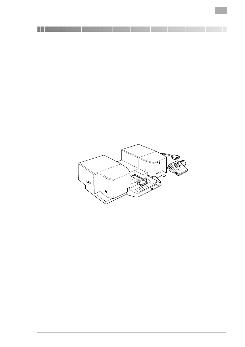
Welcome
Thank you for choosing this product.
This operator's manual explains how to operate the unit and replenish its
supplies. It also gives some troubleshooting tips as well as general
precautions to be observed when operating the unit.
To ensure the best performance and effective use of your unit, read this
manual carefully until you familiarize yourself thoroughly with the unit's
operation and features.
Please keep this manual and use it as a quick and handy reference tool
for immediately clarifying any questions that may arise.
Please follow the instructions given in this manual when handling the
system and do not touch any part of the system the manual does not
cover.
NEVER attempt to disassemble or remodel the system.
The contents of this manual are subject to change without notice.
No part of this manual may be quoted, reproduced, or translated into any
other language.
i
Page 9

CONTENTS
1 Notes to Operators........................................................1
1.1 The following safety rules should be observed ........................... 1
2 Specifications................................................................2
3 Parts Identification........................................................3
4 Explanation of the Control Unit ...................................4
5 Operation .......................................................................5
5.1 Loading the Roll Film Cartridge ..................................................... 5
5.2 Forward/reverse the Film................................................................ 6
5.3 Rewinding the Film.......................................................................... 6
5.4 Positioning the Image on the Screen ............................................ 7
5.5 Auto Vertical Scan Unit (Option).................................................... 9
How to use the Vertical Positioning Set Key ..................................... 9
5.6 Odometer (Option)......................................................................... 10
5.7 Reel Shaft Release Lever.............................................................. 10
6 Installation ...................................................................11
7 Maintaining Your Films...............................................13
7.1 ANSI Cartridge............................................................................... 13
7.2 Effect of film curl on Film Loading .............................................. 15
8 Daily Maintenance.......................................................16
9 For Key Operators Use ...............................................17
ii
Page 10

Notes to Operators
1 Notes to Operators
Information in this booklet refers only to the operation of Roll Film Carrier
22A. For further information regarding Microfilm Scanner's or Reader
Printer's, please refer to Microfilm Scanner's or Reader Printer's Operator's Manual. Please read entire manual carefully before operating Roll
Film Carrier 22A.
1.1 The following safety rules should be observed
1. The unit should be kept free from moisture, dirt, dust and exposure to
heat and direct sunlight at all times.
2. For best performance, it is recommended to use authorized supplies.
Failure to do so many cause inferior results or damage the unit, in such
case the warranty may be void.
WARNING
This equipment has been tested and found to comply with the limits for a
Class A digital device, pursuant to Part 15 of the FCC Rules. These limits
are designed to provide reasonable protection against harmful interference when the equipment is operated in a commercial environment. This
equipment generates, uses, and can radiate radio frequency energy and,
if not installed and used in accordance with the instruction manual, may
cause harmful interference to radio communications. Operation of this
equipment in a residential area is likely to cause harmful interference in
which case the use will be required to correct the interference at his own
expense.
The design and production of this unit conform to FCC regulations, and
any changes or modifications must be registered with the FCC and are
subject to FCC control. Any changes made by the purchaser of user without first contacting the manufacturer will be subject to penalty under FCC
regulations.
1
1
Page 11

2
2 Specifications
Specifications
Film Type: 16-mm Roll Cartridge Film (Leaderless Film)
-ANSI Cartridge
Film Used: 16 mm Roll Film
Film Loading: Automatic Loading
Film Rewinding
Time:
Film Feeding: By means of a Dial offering variable speeds
Film End Detection: By Encoder, Generator and Microprocessor
Image Vertical
Positioning:
Image Rotation: 360° By Prism Lens
Power
Requirement:
Power
Consumption:
Dimensions 520 (W) mm × 360 (D) mm × 145 (H) mm or
Weight 11.7 kg or 25 lbs. 26 oz
Options: Odometer, Shutter Unit, Auto Vertical Scan Unit
- Thickness2.5 Mil (0.0635 mm) to 5 Mil (0.127 mm)
- Length 2.5 Mil 225 ft (68.5 m) or less
ANSI Cartridge – Within 9 sec. / 100ft. (Approx 30.5 m)
Manual or Motor-driven
DC + 24V, DC – 24V 50/60HZ (Supplied from Microfilm
Scanner or Reader Printer)
55W
20-15/32" (W) × 14-13/16" (D) × 4-17/32" (H)
Specifications
5 Mil 110 ft (33.5 m) or less
* Specifications subject to change without notice.
2
Page 12

Parts Identification
3 Parts Identification
3
2
1
1. Reel Shaft Release Lever
2. Cartridge Port
3. Upper Glass
4. Window (Film Take-up)
5. Power Cord
6. Control Unit
7. Manual Film Advance Knob
8. Image Vertical Positioning Knob
9. Count Clear Key (Odometer... Option)
10. Display (Odometer... Option)
3456
10
9
7
8
3
Page 13

4
Explanation of the Control Unit
4 Explanation of the Control Unit
Standard Control Unit Option Control Unit
6
3
2
5
3
4
2
1. Speed Control Knob: Turning this Knob in the FORWARD direction
2. Rewind Key: Depression of this Key rewinds the roll film.
3. Misfeed Indicator: Lights up red if the film leader is not properly
4. Image Vertical Positioning Knob: Turning this Knob upward moves the image on
5. Image Vertical Positioning Keys: Depression of the key moves the image on
6. Vertical Position Indicators: Each indicator lights up to indicate that the
7. Vertical Position Set Key: Depression of this key stores the position of the
1
advances the roll film; turning it in the REVERSE
direction rewinds the film. The greater the turning
angle of the Knob the faster the scanning speed.
unwound and taken up by the Take-Up Reel
upon loading.
the Screen slightly upward; turning in downward
moves the image slightly downward.
the Screen upward.
Depression of the key moves the image
downward.
When the key is depressed, the image
returns to the central position.
corresponding Veritcal Positioning Key has been
depressed.
image on the Screen in memory.
STD
7
1
4
Page 14

Operation
5 Operation
5.1 Loading the Roll Film Cartridge
Before starting the following procedures, make sure that the Speed Control Knob is in the STOP position.
✎
If the Mars Controller is to be used, make the necessary Key entries for the target frame on the Controller before inserting the
Cartridge.
Insert the ANSI Cartridge
1
into the Loading Port on the
left of the machine.
✎
Ensure the Cartridge is
loaded in the correct direction.
5
When the Cartridge is properly inserted into position, the film leader is
2
automatically unwound and taken up by the Take-Up Reel.
✎
The Misfeed indicator on
the Control Unit lights up
red if the film leader is not
properly unwound.
If the Indicator is on, remove the Cartridge from
the Carrier and start the
procedure over.
5
Page 15

5
5.2 Forward/reverse the Film
Turn the Speed control Knob
clockwise or counterclockwise
to step through the film in the
forward or reverse direction until you reach the desired frame.
The film scanning speed is determined by the turning angle of
the Speed Control Knob. The
greater the angle the faster the
scanning speed.
✎
When the film is unwound to the trailer, turn the speed Control
Knob back to the central position to stop unwinding the film.
While the film is being forward or reverse direction, Prints can be
made by depressing the Start Key.
5.3 Rewinding the Film
To rewind the film, depress the
Rewind Button or turn the
Speed Control Knob in the REVERSE direction.
Operation
✎
When the film is completely rewound into the
Cartridge, one beep
sound to indicate that the
film has been rewound.
* It is possible to disable the beeps, for which contact your Technical Ser-
vice Representative.
When the Speed Control Knob
is used to rewind the film, be
sure to turn it back to the central
position as you reach the film
leader.
6
Page 16

Operation
5.4 Positioning the Image on the Screen
To move the image up and
down, turn the Image Vertical
Positioning Knob.
●
Turn Knob clockwise to
move the image up side.
●
Turn Knob counterclockwise to move the image
down side.
To move the image right and
left, use the Speed Control
Knob.
5
7
Page 17

5
Operation
To advance the film manually,
rotate the Manual Film Advance
Knob and, turn it clockwise.
To reverse the film manually,
Manual Film Advance Knob
and, turn it counterclockwise.
To rotate the image, turn the
Prism Rotation Knob.
8
Page 18

Operation
5.5 Auto Vertical Scan Unit (Option)
To move the image on the
Screen up and down, use the
Image Vertical Positioning
Knob and Image Vertical Positioning Keys on the Control
Unit. These controls are especially convenient when a film in
duo-format or duplex are used.
●
Image Vertical Positioning
Keys
Cause the image to move
up ( ) or down ( )
from the standard ( )
position.
●
Image Vertical Positioning
Knob
Used to move the image up
or down slightly.
How to use the Vertical Positioning Set Key
The position of the image as adjusted with the Image Vertical
Positioning Keys and/or Image
Vertical Positioning Knob can
be stored in memory. Once the
position is stored in memory,
you have only to depress the
corresponding Image Vertical
Positioning Key: when the Key
is depressed, the image is
moved to the exact position
stored in memory.
STD
Vertical Positioning Set Key
5
✎
The image position stored in memory does not change until
memory is updated.
9
Page 19

5
5.6 Odometer (Option)
The optional Odometer can be
used for image retrieval. When
a Cartridge is loaded in position, the Odometer is reset to
"0000."
To reset the Odometer during a
retrieval sequence, depress the
CLEAR Button.
Depending on the setting, an Odometer count is equivalent in film length
to either:
12.7 mm (1/2 inch) or 30.5 mm (1/10 feet).
✎
For this setting, consult your Tech. Service Rep. The Odometer
has been factory-set to 12.7 mm (1/2 inch) for one count.
5.7 Reel Shaft Release Lever
Operation
10
After the film has been rewind,
the Film Reel Shaft is not pulled
back out of the Cartridge Film.
Therefore, the Cartridge Film
cannot be slid out of Roll Film
Carrier. If this should occur,
push the Reel Shaft Release
Lever toward the rear side of
Roll Film Carrier.
Reel Shaft Release Lever
Page 20

Installation
6 Installation
NOTE
The Machine Power Switch should be turned OFF before installing the
➜
Roll Film Carrier 22A.
Align two Guide Rails on the
1
underside of the Roll Film
Carrier 22A with the right
and left edges of the Carrier
Table. Then, slide the Carrier all the way into position
along the side edges of the
Carrier Table.
6
Plug the Cable Connector of
2
the Carrier into the Socket in
the machine dedicated to
this Carrier.
11
Page 21

6
Installation
Install the Lens Unit all the
3
way into Position.
✎
To remove the Carrier from the machine, reverse the order of installation.
NOTE
The Machine Power Switch should be turned OFF before removing
➜
the Roll Film Carrier 22A.
12
Page 22

Maintaining Your Films
7 Maintaining Your Films
Use the following precautions when handling your own films.
7.1 ANSI Cartridge
Allow a length of 700mm or
1
more for the film leader (the
blank section of film at the
beginning of a reel of tape)
and the trailer (the blank
section of film at the end).
Keep the edge of the leader
2
cut straight, especially when
the edge is folded, to ensure
that the film is unwound
smoothly.
In this case, however, make
sure that the leader is
700mm or more long.
If the length of the leader is
less than 700mm, splice a
leader tape to the leader using black tape to ensure the
specified length.
700 mm
Trailer
Leader
Film
700 mm
or more
7
The film should not be twist-
3
ed 90° or more in either direction when the
approximately 300-mm-long
leader is advanced out of
the reel and held straight
downward.
13
Page 23

7
Maintaining Your Films
An excessively curled film leader
4
results in the Film Supply Reel failing to advance the film smoothly.
By studying the illustration on the
right, check to see if the curl of your
film is up to the specified allowance.
✎
If the curl deviates from the allowance, correct it as follows:
●
Splice a leader film.
●
Press the leader against the edge of a table and pull the leader to correct the curl.
14
Page 24

Maintaining Your Films
7.2 Effect of film curl on Film Loading
7
Reel
Film Loading not possible.
AWAY
R60mm
Film Loading not possible
except with 2.5 mil film.
(R60mm or more)
Film Loading not possible.
TOWARD
R35mm
Film Loading possible.
(R35mm or more)
15
Page 25

8
8 Daily Maintenance
To ensure ease of reading and Optimum Print Quality, please clean the
machine on a daily basis.
✎
The Projection lens should be removed before cleaning the Carrier Glasses.
Carrier Glasses: Wet a soft
1
cloth with water and wipe it
out well.
Then wipe the Carrier
2
Glasses Finally, dry the Carrier Glasses by wiping them
with a dry, soft cloth.
Daily Maintenance
16
Page 26

For Key Operators Use
9 For Key Operators Use
When you need to call for service, the Key Operator should be prepared
to provide the following information:
1. Your Company Name, Address, Telephone NO., Dept. Name, Floor
NO., Machine Location etc.
2. Model name, Serial number, Condition or System(s) Indication on Dis-
play etc.
For your reference purpose.
9
Model Name ROLL FILM CARRIER 22A
Installation Date
Authorized Dealer’s
Name
TEL. No.
Address
Serial No .
17
Page 27

2001. 9
The information contained in this manual is
subject to change without notice to
incorporate improvements made on the
product or products the manual covers.
 Loading...