

Konica Minolta QMS magicolor 3300 Service manual
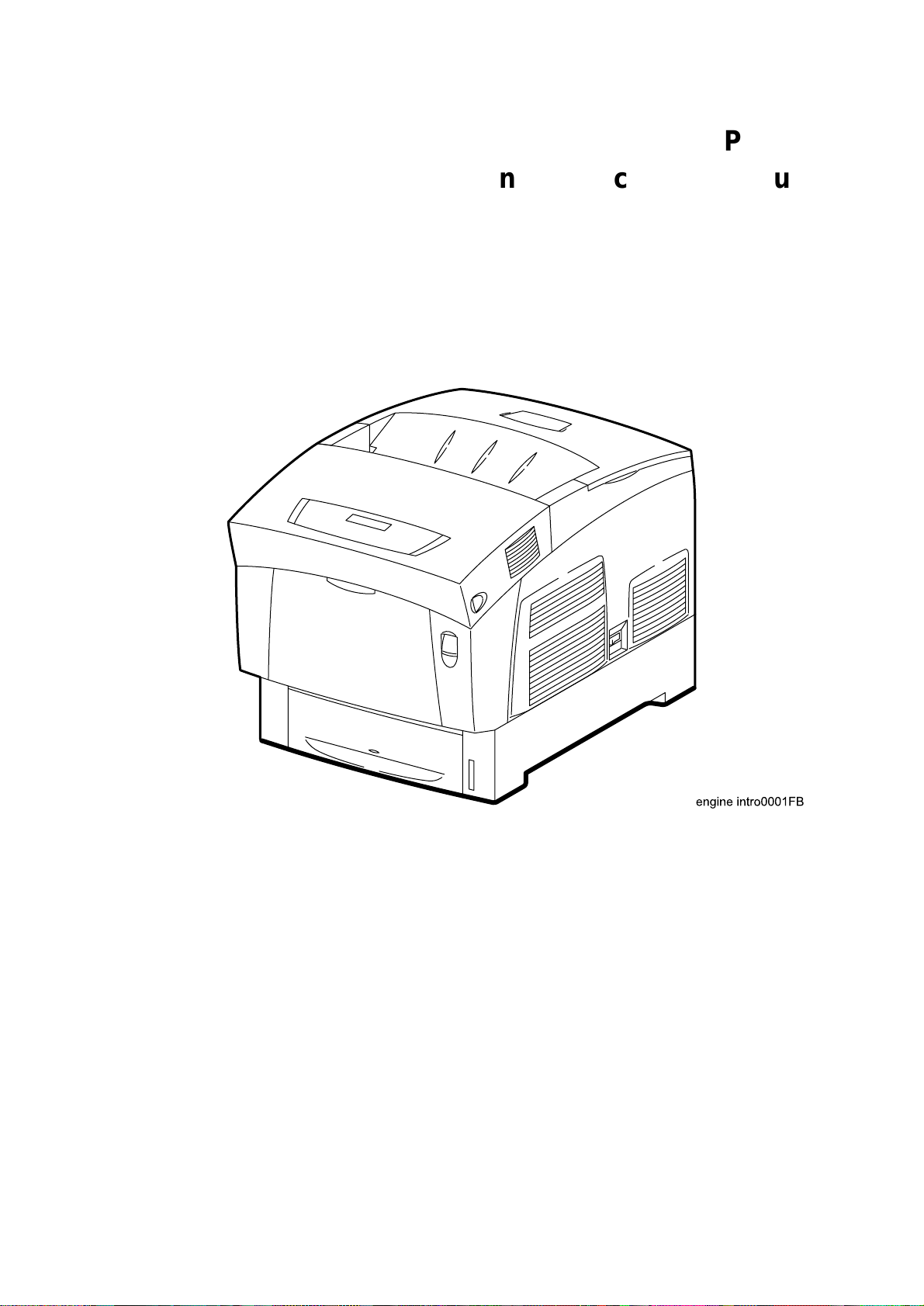
HIBANA
Laser Printer
Base Engine Technical Manual
Version 1.0

Cautions for operation
Contents of this document may be subjected to modification without previous notice.
Fuji Xerox will assume not any responsibilities for accidental or incidental damages resulting from
technical or editorial errors or omission in this manual, issue of this manual, execution of description in
this manual, or use of this manual.
This document is protected by copyright. It is not forgiven to photocopy or duplicate any part of this
document in any form without previous permission in writing from Fuji Xerox.
i
1. About this manual
This manual is a standard service manual of Fuji Xerox containing information required for
maintenance of this laser printer (standard specifications).
This manual is intended for use by OEMs under a contract with Fuji Xerox when they provide
maintenance services for this laser printer or when they prepare maintenance data. It is prohibited to
use this manual for other objects.
2. Marks giving caution
Maintenance operations requiring special cautions or additional information to descriptions of this
manual are presented as "Warning", "Caution", or "Note", according to their nature.
If instructions are not observed, death or serious injury may be caused.
If instructions are not observed, injuries of workers or physical damages to assets
(including this laser printer) may result.
Particularly important essentials for procedures, steps, rules, and others.
Reference Incidental information to descriptions.
3. Related documents
▼ Instruction
Describe operation and handling of this laser printer.
▼ Performance
Describe in detail various specifications of this laser printer.
(In the event of discrepancy between this manual and the performance specifications, the performance
specifications shall take preference.)
▼ Video
Detailed video interface specifications for this laser printer
manuals (standard manuals)
specifications
interface specifications
▼ Spare
Information on maintenance parts (spare parts) for this laser printer
parts list
ii
4. Safety
To prevent possible accidents during maintenance operation, you should observe strictly the "Warning"
and "Caution" information in this manual.
Dangerous operations and operations out of range of this manual should be absolutely avoided.
Generally various processes not covered by this manual may be required in actual operation, which
should be performed carefully always giving attention to safety.
4.1 Power source
Keep the power supply off during maintenance operation to prevent electric shock, burns and other
damages. Keep the power plug disconnected during the maintenance operation.
If the power supply should be kept connected for measurement of voltage or other similar reasons,
sufficient care should be given to prevent electric shock, by following the procedures of this manual.
While the printer is ON, never touch live parts if not required absolutely.
Power is supplied to the power switch / inlet (LVPS ASSY) even while the printer is
off. Never touch its live components.
Do not touch live parts unless otherwise specified.
iii
4.2 Driving units
When servicing gears or other driving units, be sure to turn them OFF and plug off. Drive them
manually when required.
Never touch the gears or other driving units while the printer is running.
4.3 High-temperature units
When servicing high-temperature units (securing unit, etc.), be sure to turn them OFF to prevent burns,
injuries and other troubles, remove the power plug and start service processes after they have cooled
down enough.
Immediately after completion of operation, they are still hot. Start services after
more than 40 minutes.
iv
4.4 Laser beams
•If your eyes are exposed to laser beams, you may lose your eyesight.
• Never open the cover if warning label for laser beams is attached there.
•Before disassembling and reassembling this laser printer, be sure to turn it OFF.
•When servicing this laser printer while it is running, be sure to follow the
procedures specified in this manual.
•You should understand the features of the laser beams which are capable of
having an injurious action on the human body, not to extend the danger over the
workers as well as other people around the printer.
Laser beams have features as follows:
• Frequencies are smaller in width than other beams (sun and electric bulbs) and
phases are uniform so that high monochromatic and convergence performance
can be obtained and thin beams of light can reach places at a long distance.
•Due to the high convergence, beams are concentrated in high density and high
temperature, which is dangerous to human body.
Reference: Laser beams of this laser printer is invisible rays which you cannot see.
v
4.5 Warning/caution labels
Warning labels and caution labels are attached to this laser printer to prevent accidents Check those
labels for their peeling or stain when servicing the printer.
4.5.1 Caution label for high-temperature units
vi
Unpacking the Printer
The printer must be carried horizontally with two or more persons.
Extreme care must be taken to avoid personal injuries
Check visually the printer for evidence of any damages.
Peel all tapes off the printer.
Remove protection parts (2 pieces) from the paper tray.
vii

CONTENTS
Cautions for operation...........................................................................................................i
1. About this manual............................................................................................................. ii
2. Marks giving caution.........................................................................................................ii
3. Related documents........................................................................................................... ii
4. Safety...............................................................................................................................iii
4.1 Power source.........................................................................................................................................iii
4.2 Driving unit.............................................................................................................................................iv
4.3 High-temperature units ..........................................................................................................................iv
4.4 Laser beams...........................................................................................................................................v
4.5 Warning/caution labels...........................................................................................................................vi
4.5.1 Caution label for high-temperature units........................................................................................vi
Unpacking the Printer..........................................................................................................vii
Chapter 1 Troubleshooting.............................................................................................1 - 1
Chapter 2 Operation of Diagnostic.................................................................................2 - 1
Chapter 3 Removal and Replacement Procedures........................................................3 - 1
Chapter 4 Plug/Jack(P/J) Connector Locations..............................................................4 - 1
Chapter 5 Parts List........................................................................................................5 - 1
Chapter 6 Principles of Operation..................................................................................6 - 1
Chapter 7 Wiring Diagrams and Signal Information.......................................................7 - 1
Chapter 8 Printer Specifications.....................................................................................8 - 1
viii

Chapter 1 Troubleshooting
Chapter 1 Troubleshooting CONTENTS
1. Progressing with the Troubleshooting.........................................................................1 - 1
1.1 Flow of Troubleshooting.................................................................................................................... 1 - 1
1.2 Preparatory Requirements................................................................................................................1 - 2
1.3 Cautions for Service Operations....................................................................................................... 1 - 3
1.4 Cautions for FIP Use.........................................................................................................................1 - 4
2. Level 1 FIP ..................................................................................................................1 - 6
2.1 Level 1 FIP........................................................................................................................................ 1 - 6
2.2 Flow of Level 1 FIP...........................................................................................................................1 - 6
3. Level 2 FIP ..................................................................................................................1 - 7
3.1 Level 2 FIP........................................................................................................................................ 1 - 7
3.2 Error / Status Code List.....................................................................................................................1 - 8
3.3 Operating / Clearing the Error / Status Code.................................................................................. 1 - 12
3.4 Error Code FIP................................................................................................................................1 - 15
FIP-1 Yellow Toner Cartridge Detached..............................................................................................1 - 15
FIP-2 Magenta Toner Cartridge Detached...........................................................................................1 - 16
FIP-3 Cyan Toner Cartridge Detached ................................................................................................1 - 17
FIP-4 Black Toner Cartridge Detached................................................................................................ 1 - 18
FIP-5 PHD Detached ........................................................................................................................... 1 - 19
FIP-6 BTR Detached............................................................................................................................ 1 - 20
FIP-7 Fuser Detached.......................................................................................................................... 1 - 21
FIP-8 CRUM ID Error...........................................................................................................................1 - 22
FIP-9 Media Type Mismatch................................................................................................................ 1 - 23
FIP-10 Feed Jam................................................................................................................................. 1 - 24
FIP-11 Regi Jam.................................................................................................................................. 1 - 27
FIP-12 Fuser Jam................................................................................................................................ 1 - 28
FIP-13 Duplex Jam.............................................................................................................................. 1 - 29
FIP-14 ROS Failure ............................................................................................................................. 1 - 30
FIP-15 Fuser Failure............................................................................................................................1 - 31
FIP-16 NV-RAM Error.......................................................................................................................... 1 - 32
FIP-17 ADC Sensor Error....................................................................................................................1 - 33
FIP-18 Fan Motor Failure.....................................................................................................................1 - 34
FIP-19 Low Density Error..................................................................................................................... 1 - 36
FIP-20 Firmware Error......................................................................................................................... 1 - 37
FIP-21 Environment Sensor Error........................................................................................................1 - 38
FIP-22 Yellow Toner Empty................................................................................................................. 1 - 39
FIP-23 Magenta Toner Empty..............................................................................................................1 - 40
FIP-24 Cyan Toner Empty...................................................................................................................1 - 41
FIP-25 Black Toner Empty...................................................................................................................1 - 42
FIP-26 PHD Life Over.......................................................................................................................... 1 - 43
FIP-27 BTR Life Over ..........................................................................................................................1 - 44
FIP-28 Fuser Life Over ........................................................................................................................1 - 45
FIP-29 ADC Sensor Dustiness ............................................................................................................1 - 46
FIP-30 Front Cover .............................................................................................................................. 1 - 47
FIP-31 Yellow Toner Near Empty ........................................................................................................1 - 48
FIP-32 Magenta Toner Near Empty..................................................................................................... 1 - 49

Chapter 1 Troubleshooting
FIP-33 Cyan Toner Near Empty ..........................................................................................................1 - 50
FIP-34 Black Toner Near Empty..........................................................................................................1 - 51
FIP-35 PHD Life Warning .................................................................................................................... 1 - 52
FIP-36 BTR Life Warning.....................................................................................................................1 - 53
FIP-37 Fuser Life Warning...................................................................................................................1 - 54
FIP-38 ADC Sensor Dustiness ............................................................................................................1 - 55
FIP-39 Tray 1 Paper Near Empty ........................................................................................................1 - 56
FIP-40 Paper Empty ............................................................................................................................ 1 - 57
FIP-41 Upper Cassette Detached........................................................................................................1 - 58
FIP-42 Full Stack ................................................................................................................................. 1 - 59
FIP-43 Yellow Toner Empty 2..............................................................................................................1 - 60
FIP-44 Magenta Toner Empty 2...........................................................................................................1 - 61
FIP-45 Cyan Toner Empty 2................................................................................................................1 - 62
FIP-46 Black Toner Empty 2................................................................................................................1 - 63
FIP-47 PHD Life Over 2....................................................................................................................... 1 - 64
FIP-48 BTR Life Over 2 .......................................................................................................................1 - 65
FIP-49 Fuser Life Over 2 .....................................................................................................................1 - 66
FIP-50 CRUM ID Error(TC-Y/TC-M/TC-C/TC-K) .................................................................................1 - 67
FIP-51 CRUM ID Error(Fuser) .............................................................................................................1 - 68
FIP-52 CRUM Error(TC-Y/TC-M/TC-C/TC-K)......................................................................................1 - 69
FIP-53 Y/M/C/K Toner Tape Staying ...................................................................................................1 - 70
3.5 Image Troubleshooting ...................................................................................................................1 - 71
P1 "Light (Undertoned) Prints".............................................................................................................1 - 72
P2 "Blank Prints".................................................................................................................................. 1 - 73
P3 "Black Prints"..................................................................................................................................1 - 74
P4 "Vertical Band Deletions"................................................................................................................ 1 - 75
P5 "Horizontal Band Deletions" ...........................................................................................................1 - 76
P6 "Black (color) spots" ....................................................................................................................... 1 - 77
P7 "Background"..................................................................................................................................1 - 78
P8 "Skewed Image" ............................................................................................................................. 1 - 79
P9 "Crease" .........................................................................................................................................1 - 80
P10 "Unfused Image or Image Easily Rubs off of Page"..................................................................... 1 - 81
3.6 Other FIP ........................................................................................................................................ 1 - 82
FIP-AC..................................................................................................................................................1 - 82
FIP-DC..................................................................................................................................................1 - 83
4. Preventive Maintenance............................................................................................1 - 84
Chapter 1 Troubleshooting
This manual is based on the standard specifications of Fuji Xerox on the
assumption that the printer controller is working properly.
When the printer controller controls operation directly or any OEM has its unique
specifications, the operation may be different from description in this manual.
Troubleshooting in this manual assumes use of Diag. tools (maintenance tools).
However, the troubleshooting allows for the case where the Diag tools are not
used. You can correct troubles according to these troubleshooting procedures
after understanding them well.
1. Progressing with the Troubleshooting
After making sure of actual condition of a trouble, proceed with the troubleshooting process efficiently
making use of the Fault Isolation Procedure (FIP), Operation of Diag. tools (Chapter 2), Wire
connecting diagram (Chapter 7), and Principle of operation (Chapter 6).
1.1 Flow of Troubleshooting
Flow of the troubleshooting is as follows:
Prior check
Condition check
Start
Level 1 FIP
Trouble recovery check
Preventive
maintenance
End
Diagnostic operation
Operational principle
Wiring connection
diagram
Level 2 FIP
1 – 1

Chapter 1 Troubleshooting
1.2 Preparatory Requirements
Be sure to check the following items before starting the troubleshooting procedures:
1) Voltage of the power supply is within the specifications (measure the voltage at the electric outlet).
2) Power cord is free from breakage, short-circuit, disconnected wire, or incorrect connection in the
power cord.
3) The laser printer is properly grounded.
4) The laser printer is not installed at a place subjected to too high temperature, too high humidity, too
low temperature, too low humidity or rapid change of temperature.
5)
The laser printer is not installed close to water service, humidifier, heat generating unit, or fire, in
very dusty place, or a place exposed to air flow from the air conditioning system.
6) The laser printer is not installed in a place where volatile gas or inflammable gas is generated.
7) The laser printer is not installed under direct sunbeams.
8) The laser printer is installed in a well-ventilated place.
9) The laser printer is installed on a stout and stable plane.
10) Paper used meets specifications (standard paper is recommendable).
11) The laser printer is handled properly.
12) Parts which should be periodically replaced are replaced each time when specified number of
sheets have been printed.
1 – 2
1.3 Cautions for Service Operations
1) Be sure to remove the power cord except when it is specifically required.
If the printer is kept ON, never touch the conductive parts while it is not specifically
required.
The power switch/inlet of LVPS is live even while the power supply is cut off. Never
touch the live parts.
Chapter 1 Troubleshooting
2) When checking some parts with covers removed and with the interlock and safety and power
switches ON, remove the connector (P/J151) on the ROS ASSY except when it is specifically
required.
When checking some parts with covers removed and with the interlock and safety
and power switches ON, laser beams may be irradiated from the ROS ASSY. Since
it is dangerous, be sure to remove the connector (P/J151) while it is not required.
3) When checking some parts with the left cover removed and power ON, be sure to remove the
connector (P/J5011) on the HVPS while it is not required.
When checking some parts with the left cover removed and power ON, high voltage
may be applied by the HVPS. Be sure to remove the connector (P/J5011) on the
HVPS.
When connecting the connector (P/J5011) on the HVPS according to the
instructions of the FIP, never touch the HVPS and parts of high voltage.
4) When using Diag. tools or other tools of high voltage, be sure to keep them covered except when
otherwise specified.
When using Diag.Tool or other tools of high voltage, never touch parts of high
voltage.
When using Diag.Tool or other tools of high voltage, be sure to follow the
procedure of this manual.
5) When operating the driving units using the Diag or other tools, be sure to keep them covered
unless otherwise specified.
When operating the driving units using the Diag or other tools, never touch the
driving units. When operating the driving units using Diag or other tools, be sure
to observe the procedures in this manual.
6) When touching hot parts, be careful not to get burnt.
7) Workers should wear a wrist band or the like to remove static electricity from their body , grounding
their body while working.
1 – 3
1.4 Cautions for FIP Use
Chapter 1 Troubleshooting
1) It is assumed in the FIP that the printer controller (CONTROLLER PWB) is normally functioning. If
any trouble cannot be corrected by troubleshooting, replace the printer controller with a normal one
and check for proper operation again.
If the trouble is not still corrected, replace the major parts and then related parts in succession and
confirm according to the procedure of the "Initial check" and "Major check parts".
2) When troubleshooting according to the FIP, normal HBN NCU PWB, PHD ASSY or other parts
may be necessary for isolation of failed parts. Prepare them in advance.
3) In the initial check according to the FIP, check only items which can be simply checked.
4) In the initial check according to the FIP, check the constitutive parts of the major check parts and
related parts, as well as major check parts.
5) When working with the printer, Be sure to remove the power cord except when required specifically. Never touch live parts if not required, while the power cord is connected.
6) Connector condition is denoted as follows:
[P/J12] ’ Connector (P/J12) is connected.
[P12] ’ Plug side with the connector (P/J12) removed (except when attached directly to the
board).
[J12] ’ Jack side with the connector (P/J12) removed (except when attached directly to the
board).
7) [P/J1-2PIN <=> P/J3-4PIN] in the FIP means measurement with the plus side of the measuring
instrument connected to [P/J1] and the minus side to [4PIN] of [P/J3].
8) [P/J<=>P/12] in the FIP means measurement for all terminals corresponding between [P/J1] and
[P/J2] referring to "Wire connecting diagram".
9) In [P/J1-2PIN <=> P/J3-4PIN] in the FIP where voltage is measured, [P/J3-4PIN] on the rear minus
side is always at the AG (analog ground), SG (signal ground), or RTN (return).
Therefore, after checking of proper continuity between AGs, SGs, or RTNs respectively, the rear
minus side can be connected to the PIN of AG, SG or RTN instead of [P/J3-4PIN].
However, care should be taken not to mistake since [AG], [SG], and [RTN] are not on the same
level.
10) Measure the voltage of small connectors with the special tool. Handle the tool with care, as the
leading edge of the tool is pointed.
11) When measuring the voltage, set the PDH ASSY, FUSER ASSY, BRT ASSY and paper tray, close
the FRONT COVER ASSY and power ON if not required specifically.
12) Numerical values in the FIP are only for standard. If numerical values are approximate, they
should be considered permissible.
1 – 4

Chapter 1 Troubleshooting
13) Parts which are always removed to check as indicated in the FIP and procedures for that purpose
are not specifically referred to here. They should be handled carefully.
14) "Replacement" in the FIP indicates replacement of parts which are considered to be the source of
trouble to be checked after replacing those parts, assemblies containing them, or parts (HIGH
ASSY).
15) In the FIP, the paper pick-up unit by means of the paper tray at the lower part of the printer is
referred to as "try 1", the first level of the paper pick-up unit feeder unit as "try 2", and the second
level as the "tray3".
16) In the FIP, existence and non-existence of Diag tools (maintenance tools,) are distinguished in
some cases. Correct troubles according to the instructions in the FIP.
17) In the FIP, procedures are differentiated depending on specifications. Correct troubles according
to the instructions in the FIP.
18) For optional parts, some troubleshooting procedure may follow the manual for those options, of
which you should take note.
Keep those manuals for the optional parts when required.
1 – 5
2. Level 1 FIP
2.1 Level 1 FIP
Chapter 1 Troubleshooting
The level 1 FIP is the first step for trouble diagnosis. The level 1 FIP isolates the presence of various
troubles including error codes, and the level 2 FIP provides a guide for proceeding of the
troubleshooting.
2.2 Flow of Level 1 FIP
Ask the operator about trouble status
Is operator’s operating method correct?
Is error code displayed?
Y
N
Y
N
Instruct how to operate
troubleshooting
Level 2 FIP
Is trouble related to
image quality?
Y
Image quality
N
Print in the mode where the trouble
occurred to check if error or jam
occurs
Y
Level 2 FIP Other FIP
N
1 – 6

3. Level 2 FIP
3.1 Level 2 FIP
Chapter 1 Troubleshooting
The Level 2 FIP is the trouble diagnostic procedure to sort various troubles in addition to the error
codes. In the troubleshooting, executing the steps given in the FIP or checking procedure allows you to
find out a cause of trouble in a short time.
1 – 7
3.2 Error / Status Code List
This error / status cord list is based on the interface specifications.
Chapter 1 Troubleshooting
Error / status code
51h,C1h-status 1-0
51h,C1h-status 1-1
51h,C1h-status 1-2
51h,C1h-status 1-3
51h,C1h-status 1-4
51h,C1h-status 1-5
51h,C1h-status 1-6
51h,C1h-status 2-0
51h,C1h-status 2-1
51h,C1h-status 2-2
51h,C1h-status 2-3
51h,C1h-status 2-4
51h,C1h-status 2-6
54h,C4h-0
54h,C4h-1
54h,C4h-2
54h,C4h-3
Since the error / status codes are represented by the printer controller on the
printer, display on the printer is different from the one shown below.
Name of error
Contents of error
Yellow Toner Cartridge Detached
Cartridge sensor detected no-toner cartridge.
Magenta Toner Cartridge Detached
Cartridge sensor detected no-toner cartridge.
Cyan Toner Cartridge Detached
Cartridge sensor detected no-toner cartridge.
Black Toner Cartridge Detached
Cartridge sensor detected no-toner cartridge.
PHD Detached
Machine detected no-PHD ASSY.
BTR Detached
Machine detected no-BTR ASSY.
Fuser Detached
Machine detected no-FUSER ASSY.
CRUM ID Error (TC-Y)
ASSY ID is not as recorded.
CRUM ID Error (TC-M)
ASSY ID is not as recorded.
CRUM ID Error (TC-C)
ASSY ID is not as recorded.
CRUM ID Error (TC-K)
ASSY ID is not as recorded.
CRUM ID Error(PHD)
ID of PHD ASSY is different from the recorded ID.
CRUM ID Error (Fuser)
Fuser ASSY ID is not as recorded.
Media Type Mismatch
1. Plain paper was detected in the printing by selecting OHP.
2. OHP was detected in the printing by selecting plain paper.
Feed Jam
Regi sensor cannot detect paper within specified time.
Regi Jam
Regi sensor cannot detect passage of paper within specified time.
Fuser Jam
Exit sensor cannot detect passage of paper within specified time.
Reference
FIP
50
50
50
50
51
10
11
12
1
2
3
4
5
6
7
8
9
1 – 8
Chapter 1 Troubleshooting
Error / status code
54h,C4h-4
55h,C5h-status 1-0
55h,C5h-status 1-1
55h,C5h-status 1-2
55h,C5h-status 1-3
55h,C5h-status 1-4
55h,C5h-status 1-5
55h,C5h-status 1-6
55h,C5h-status 1-7
55h,C5h-status 2-0
55h,C5h-status 2-1
55h,C5h-status 2-2
55h,C5h-status 2-3
56h,C6h-0
56h,C6h-1
56h,C6h-2
56h,C6h-3
Name of error
Contents of error
Duplex Jam
Duplex jam sensor cannot detect passage of paper within specified
time.
ROS Failure
1. Laser power down.
2. SOS signal not detected.
Fuser Failure
1. Temperature exceeding 235°C detected consecutively 4 times.
2. Temperature below 120°C detected consecutively 4 times.
3. Resistance value of STS sensor over 2437KW detected
consecutively 4 times.
4. Target temperature is not reached more than 60 seconds after
the fuser lamp lighted up.
5. After the target temperature is reached, the fuser lamp was kept
ON for more than specified time.
6. Value of the STS sensor does not change after the lamp lights up.
7. Temperature exceeding 230°C detected during printing process
consecutively twice.
NV-RAM Error
Error of NV-RAM
ADC Sensor Error
Power down of ADC sensor
Fan Motor Failure
Failure of Fan Motor
Low Density Error
Toner density is low.
Firmware Error
Error of software
Environment Sensor Error
1. The temperature over +100°C or below -20°C was detected.
2. The humidity over 100% was detected.
CRUM Error (TC-Y)
CRUM (TC-Y) Communication Error
CRUM Error (TC-M)
CRUM (TC-M) Communication Error
CRUM Error (TC-C)
CRUM (TC-C) Communication Error
CRUM Error (TC-K)
CRUM (TC-K) Communication Error
Yellow Toner Empty
Yellow toner emptied.
Magenta Toner Empty
Magenta toner emptied.
Cyan Toner Empty
Cyan toner emptied.
Black Toner Empty
Black toner emptied.
Reference
FIP
13
14
15
16
17
18
19
20
21
52
52
52
52
22
23
24
25
1 – 9
Chapter 1 Troubleshooting
Error / status code
56h,C6h-4
56h,C6h-5
56h,C6h-6
57h,C7h-0
57h,C7h-1
57h,C7h-2
57h,C7h-3
57h,C7h-6
57h,C7h-7
58h,C8h-0
58h,C8h-1
58h,C8h-2
58h,C8h-3
58h,C8h-4
58h,C8h-5
58h,C8h-6
58h,C8h-7
59h,C9h-0
59h,C9h-1
59h,C9h-2
5Ah,CAh-0
5Bh,CBh-0
5Bh,CBh-1
Name of error
Contents of error
PHD Life Over
PHD ASSY life expired.
BTR Life Over
BTR ASSY life expired.
Fuser Life Over
FUSER ASSY life expired.
Y Toner Tape Staying
Y Toner Tape not Pulled out Error
M Toner Tape Staying
M Toner Tape not Pulled out Error
C Toner Tape Staying
C Toner Tape not Pulled out Error
K Toner Tape Staying
K Toner Tape not Pulled out Error
CTD Sensor Dustiness
CTD sensor signal level below specified value.
Front Cover
Front cover open.
Yellow Toner Near Empty
Yellow toner shortage.
Magenta Toner Near Empty
Magenta toner shortage
Cyan Toner Near Empty
Cyan toner shortage
Black Toner Near Empty
Black toner shortage
PHD Life Warning
PHD ASSY life running out.
BTR Life Warning
BTR ASSY life running out.
Fuser Life Warning
Fuser life running out.
ADC Sensor Dustiness
ADC sensor signal level below specified value.
Paper Near Empty
Paper in the paper cassette running out.
Paper Empty
Paper in the paper cassette exhausted.
Upper Cassette Detached
Paper cassette dislocated.
Full Stack
Delivery tray full of paper
Yellow Toner Empty 2
Yellow toner emptied.
Magenta Toner Empty 2
Magenta toner emptied.
Reference
FIP
26
27
28
53
53
53
53
29
30
31
32
33
34
35
36
37
38
39
40
41
42
43
44
1 – 10

Chapter 1 Troubleshooting
Error / status code
5Bh,CBh-2
5Bh,CBh-3
5Bh,CBh-4
5Bh,CBh-5
5Bh,CBh-6
Cyan Toner Empty 2
Cyan toner emptied.
Black Toner Empty 2
Black toner emptied.
PHD Life Over 2
PHD ASSY life expired.
BTR Life Over 2
BTR ASSY life expired.
Fuser Life Over 2
FUSER ASSY life expired.
Name of error
Contents of error
Reference
FIP
45
46
47
48
49
1 – 11
3.3 Operating / Clearing the Error / Status Code
Chapter 1 Troubleshooting
Error / status code
51h,C1h-status 1-0
51h,C1h-status 1-1
51h,C1h-status 1-2
51h,C1h-status 1-3
51h,C1h-status 1-4
51h,C1h-status 1-5
51h,C1h-status 1-6
51h,C1h-status 2-0
51h,C1h-status 2-1
51h,C1h-status 2-2
51h,C1h-status 2-3
51h,C1h-status 2-4
51h,C1h-status 2-6
54h,C4h-0
54h,C4h-1
54h,C4h-2
54h,C4h-3
54h,C4h-4
55h,C5h-status 1-0
In the table below, "shutdown" means that control over motors, ROS ASSY,
FUSER ASSY and so on is stopped after a certain time.
In the table below, "print" means that printing is continued even if error / status
code is generated.
Operation
Method of clear
Shutdown
Toner cartridge replacement
Shutdown
Toner cartridge replacement
Shutdown
Toner cartridge replacement
Shutdown
Toner cartridge replacement
Shutdown
PHD ASSY replacement
Shutdown
BTR ASSY replacement
Shutdown
Power OFF/ON after replacing the FUSER ASSY
Shutdown
Replace Toner Cartridge Y
Shutdown
Replace Toner Cartridge M
Shutdown
Replace Toner Cartridge C
Shutdown
Replace Toner Cartridge K
Shutdown
PHD ASSY replacement
Shutdown
Replace Fuser ASSY
Shutdown
Power OFF/ON after removing the jam paper
Next paper is not picked up after a sheet of paper is delivered during operation
Open and close the front cover after removing the jammed paper
Shutdown
Open and close the front cover after removing the jammed paper
Shutdown
Open and close the front cover after removing the jammed paper
Shutdown
Open and close the front cover after removing the jammed paper
Shutdown
Power ON/OFF
1 – 12
Chapter 1 Troubleshooting
Error / status code
55h,C5h-status 1-1
55h,C5h-status 1-2
55h,C5h-status 1-3
55h,C5h-status 1-4
55h,C5h-status 1-6
55h,C5h-status 1-7
55h,C5h-status 2-0
55h,C5h-status 2-1
55h,C5h-status 2-2
55h,C5h-status 2-3
56h,C6h-0
56h,C6h-1
56h,C6h-2
56h,C6h-3
56h,C6h-4
56h,C6h-5
56h,C6h-6
57h,C7h-0
57h,C7h-1
57h,C7h-2
57h,C7h-3
57h,C7h-6
57h,C7h-7
Operation
Method of clear
Shutdown
Power ON/OFF
Shutdown
Power ON/OFF
Shutdown
Power ON/OFF
Shutdown
Power ON/OFF
Shutdown
Power ON/OFF
Shutdown
Power ON/OFF
Shutdown
Power ON/OFF
Shutdown
Power ON/OFF
Shutdown
Power ON/OFF
Shutdown
Power ON/OFF
Shutdown
Toner cartridge replacement
Shutdown
Toner cartridge replacement
Shutdown
Toner cartridge replacement
Shutdown
Toner cartridge replacement
Shutdown
PHD ASSY replacement
Shutdown
BTR ASSY replacement
Shutdown
Clearing the counter after replacing the FUSER ASSY
Shutdown
Pull out Tape
Shutdown
Pull out Tape
Shutdown
Pull out Tape
Shutdown
Pull out Tape
Print
Open and close the front cover after cleaning the sensor
Shutdown
Close the front cover
1 – 13
Chapter 1 Troubleshooting
Error / status code
58h,C8h-0
58h,C8h-1
58h,C8h-2
58h,C8h-3
58h,C8h-4
58h,C8h-5
58h,C8h-6
58h,C8h-7
59h,C9h-0
59h,C9h-1
59h,C9h-2
5Ah,CAh-0
5Bh,CB-0
5Bh,CB-1
5Bh,CB-2
5Bh,CB-3
5Bh,CB-4
5Bh,CB-5
5B,CB-6
Operation
Method of clear
Print
Toner cartridge replacement
Print
Toner cartridge replacement
Print
Toner cartridge replacement
Print
Toner cartridge replacement
Print
PHD ASSY replacement
Print
BTR ASSY replacement
Print
Replace the FUSER ASSY and clear the counter
Print
Clean the sensor and open and close the front cover
Print
Replenish the paper
Print (Paper cannot be delivered from the cassette)
Replenish the paper
Print (Paper cannot be delivered from the cassette)
Paper cassette replacement
Print
Take out paper from the delivery tray
Shutdown
Toner cartridge replacement
Shutdown
Toner cartridge replacement
Shutdown
Toner cartridge replacement
Shutdown
Toner cartridge replacement
Shutdown
PHD ASSY replacement
Shutdown
BTR ASSY replacement
Shutdown
Clearing the counter after replacing the FUSER ASSY
1 – 14
3.4 Error Code FIP
FIP-1 Yellow Toner Cartridge Detached
Chapter 1 Troubleshooting
Step Check
Initial setting
Check the following for evidence of fault.
Cartridge replacing condition
SW TCRU ASSY (Y) replacing condition
1
SW TCRU ASSY (Y) actuator replacing condition
SW TCRU ASSY SW TCRU ASSY (Y) connector replacing
condition
Checking SW TCRU ASSY
2
Does SW TCRU ASSY function normally?
Using diagnostic tool, check by Digital Input Test.
Checking PWBA HBN DRV for signal
3
Is P/J51-13PIN <=> P/J51-14PIN 0VDC?
Checking SW TCRU ASSY (Y) for signal
4
Is P/J342-5PIN<=>P/J342-4PIN 0VDC?
Checking SW TCRU ASSY (Y) for continuity
5
Is P342-5PIN <=> P342-4PIN of SW TCRU ASSY (Y)
continuous normally?
Checking HARNESS ASSY TNR for continuity
6
Is J51 <=> J342 continuous normally?
Checking PWBA HBN DRV for signal
7
Is P/J42-4PIN<=>P/J42-14PIN 0VDC?
Checking PWBA HBN MCU for signal
8
Is P/J12-27PIN <=> P/J12-17PIN of PWBA HBN MCU
0VDC?
Checking HARNESS ASSY DRV2 for continuity
9
Is J12 <=> J42 continuous normally?
Remedy
Yes No
With tool
Replace the parts
concerned
Replace PWBA
HBN MCU
Go to step [7] Go to step [4]
Go to step [6] Go to step [5]
Go to step [6]
Go to step [7]
Go to step [8]
Replace PWBA
HBN MCU
Replace PWBA
HBN MCU
Go to step [2]
Without tool
Go to step [3]
Go to step [3]
Replace SW
TCRU ASSY (Y)
Replace
HARNESS ASSY
TNR
Replace PWB
HBN DRV
Go to step [9]
Replace
HARNESS ASSY
DRV2
1 – 15
FIP-2 Magenta Toner Cartridge Detached
Chapter 1 Troubleshooting
Step Check
Initial setting
Check the following for evidence of fault.
Cartridge replacing condition
1
SW TCRU ASSY (M) replacing condition
SW TCRU ASSY (M) actuator replacing condition
SW TCRU ASSY (M) connector replacing condition
Checking SW TCRU ASSY
2
Does SW TCRU ASSY function normally?
Using diagnostic tool, check by Digital Input Test.
Checking PWBA HBN DRV for signal
3
Is P/J51-13PIN <=> P/J51-15PIN 0VDC?
Checking SW TCRU ASSY(M) for signal
4
Is P/J342-5PIN <=> P/J342-3PIN 0VDC?
Checking SW TCRU ASSY (Y) for continuity
5
Is P342-5PIN <=> P342-3PIN of SW TCRU ASSY (Y)
continuous normally?
Checking HARNESS ASSY TNR for continuity
6
Is J51 <=> J342 continuous normally?
Checking PWBA HBN DRV for signal
7
Is P/J42-5PIN <=> P/J42-14PIN 0VDC?
Checking PWBA HBN MCU for signal
8
Is P/J11-26PIN <=> P/J11-17PIN of HBN MCU WITHCPU
PWB 0VDC?
Checking HARNESS ASSY DRV2 for continuity
9
Is J12 <=> J42 continuous normally?
Remedy
Yes No
With tool
Replace the parts
concerned
Replace PWBA
HBN MCU
Go to step [7] Go to step [4]
Go to step [6] Go to step [5]
Go to step [6]
Go to step [7]
Go to step [8]
Replace PWBA
HBN MCU
Replace PWBA
HBN MCU
Go to step [2]
Without tool
Go to step [3]
Go to step [3]
Replace SW
TCRU ASSY (M)
Replace
HARNESS ASSY
TNR
Replace PWB
HBN DRV
Go to step [9]
Replace
HARNESS ASSY
DRV2
1 – 16
FIP-3 Cyan Toner Cartridge Detached
Chapter 1 Troubleshooting
Step Check
Initial setting
Check the following for evidence of fault.
Cartridge replacing condition
1
SW TCRU ASSY (C) replacing condition
SW TCRU ASSY (C) actuator replacing condition
SW TCRU ASSY (C) connector replacing condition
Checking SW TCRU ASSY
2
Does SW TCRU ASSY function normally?
Using diagnostic tool, check by Digital Input Test.
Checking PWBA HBN DRV for signal
3
Is P/J51-13PIN <=> P/J51-16PIN 0VDC?
Checking SW TCRU ASSY (C) for signal
4
Is P/J342-5PIN <=> P/J342-2PIN 0VDC?
Checking SW TCRU ASSY (C) for continuity
5
Is P342-5PIN <=> P342-2PIN of SW TCRU ASSY (C)
continuous normally?
Checking HARNESS ASSY TNR for continuity
6
Is J51 <=> J342 continuous normally?
Checking PWBA HBN DRV for signal
7
Is P/J42-6PIN <=> P/J42-14PIN 0VDC?
Checking PWBA HBN MCU for signal
8
Is P/J12-25PIN <=> P/J12-17PIN of PWBA HBN MCU
0VDC?
Checking HARNESS ASSY DRV2 for continuity
9
Is J12 <=> J42 continuous normally?
Remedy
Yes No
With tool
Replace the parts
concerned
Replace PWBA
HBN MCU
Go to step [7] Go to step [4]
Go to step [6] Go to step [5]
Go to step [6]
Go to step [7]
Go to step [8]
Replace PWBA
HBN MCU
Replace PWBA
HBN MCU
Go to step [2]
Without tool
Go to step [3]
Go to step [3]
Replace SW
TCRU ASSY (C)
Replace
HARNESS ASSY
TNR
Replace PWB
HBN DRV
Go to step [9]
Replace
HARNESS ASSY
DRV2
1 – 17
FIP-4 Black Toner Cartridge Detached
Chapter 1 Troubleshooting
Step Check
Initial setting
Check the following for evidence of fault.
Cartridge replacing condition
1
SW TCRU ASSY (K) replacing condition
SW TCRU ASSY (K) actuator replacing condition
SW TCRU ASSY (K) connector replacing condition
Checking SW TCRU ASSY
2
Does SW TCRU ASSY function normally?
Using diagnostic tool, check by Digital Input Test.
Checking PWBA HBN DRV for signal
3
Is P/J51-13PIN<=>P/J51-17PIN 0VDC?
Checking SW TCRU ASSY (K) for signal
4
Is P/J342-5PIN<=>P/J342-1PIN 0VDC?
Checking SW TCRU ASSY (K) for continuity
5
Is P342-5PIN <=> P342-1PIN of SW TCRU ASSY (K)
continuous normally?
Checking HARNESS ASSY TNR for continuity
6
Is J51 <=> J342 continuous normally?
Checking PWBA HBN DRV for signal
7
Is P/J42-3PIN <=> P/J42-14PIN 0VDC?
Checking PWBA HBN MCU for signal
8
Is P/J12-28PIN <=> P/J12-17PIN of PWBA HBN MCU
0VDC?
Checking HARNESS ASSY DRV2 for continuity
9
Is J12 <=> J42 continuous normally?
Remedy
Yes No
With tool
Replace the parts
concerned
Replace PWBA
HBN MCU
Go to step [7] Go to step [4]
Go to step [6] Go to step [5]
Go to step [6]
Go to step [7]
Go to step [8]
Replace PWBA
HBN MCU
Replace PWBA
HBN MCU
Go to step [2]
Without tool
Go to step [3]
Go to step [3]
Replace SW
TCRU ASSY (K)
Replace
HARNESS ASSY
TNR
Replace PWB
HBN DRV
Go to step [9]
Replace
HARNESS ASSY
DRV2
1 – 18
FIP-5 PHD Detached
Chapter 1 Troubleshooting
Step Check
Initial setting
Check the following for evidence of fault.
1
PHD ASSY replacing condition
PWBA CRUM in PHD ASSY replacing condition
Checking PWBA CRUM
2
Is PWBA CRUM connector connected to the
harness connector normally?
Checking HARNESS ASSY CRUM for continuity
3
Is J170 <=> J71 continuous normally?
Checking HARNESS ASSY EEPROM for continuity
4
Is J17 <=> J140 continuous normally?
Checking PHD ASSY
5
Replace new PHD ASSY, and check if an error occurs
Remedy
Yes No
Replace the parts
concerned
Go to step [3]
Go to step [4]
Go to step [5]
Replace PWBA
HBN MCU
Go to step [2]
Replace
HARNESS ASSY
CRUM
Replace
HARNESS ASSY
CRUM
Replace
HARNESS ASSY
EEPROM
End of work
1 – 19
 Loading...