

Page 1

QMS ® 860 Print System
User’s Guide
1800261-001D
Page 2

Trademark Acknowledgements
The following are trademarks or registered trademarks of their respective owners. Other
product names mentioned in this manual may also be trademarks or registered trademarks
of their respective owners. Registered trademark s are registered in the United States Patent
and Trademark Office; some trademarks may also be registered in other countries. QMS
the QMS logo
a trademark of Adobe Systems, Incorporated for a page description language and may be
registered in certain jurisdictions. Throu ghout this user’s guide, “Pos tScript Level 2” is used
to refer to a set of capabilities defined by Adobe Systems for its PostScript L evel 2 page
description language. These capabilities, among others, are implemented in this product
through a program designed and developed by QMS which is compatible with Adobe’s
PostScript Level 2 language. Adobe Illustrator
Aldus PageMaker
EtherTalk
AutoDesk, Inc. CompuServe
DEC
Design, Inc. Ethernet
Corporation. Helvetica
, LaserJet, HP PCL, HP-GL/Hewlett-Packard Company. IBM, AT, Token-
HP
Ring
Intel
Dingbats
copyrighted by the International Typeface Corporation. Lotus
/Lotus Development Corporation. Micrografx, Micrografx Designer/Micrografx, Inc.
Microsoft
MultiMate
NetWare
Samsung
Sprint
Microsystems, Inc. UNIX
Software, Inc., a Xerox Company. WingZ
WordPerfect
, PS Executive Series, Crown, the Crown logo/QMS. PostScript is
, LaserWriter, Macintosh, LocalTalk/Apple Computer, Inc. AutoCad/
, DECnet, LN03/Digital Equipment Corporation. Dreams/Innovative Data
, Aldus FreeHand/Aldus Corporation. Apple, AppleTalk,
/H & R Block. Dataproducts/Dataproducts Corporation.
/Xerox Corporation. Harvard Graphics/Software Publishing
, Times, Palatino/Linotype-Hell AG and/or its subsidiaries.
/Adobe Systems Incorporated. Aldus,
, DisplayWrite, IBM PC, PC/XT/International Bus iness Machines Corpora tion.
/Intel Corporation. ITC Avant Garde Gothic, ITC Zapf Chancery, ITC Zapf
, ITC Bookman/International Typeface Corporation. ITC typefaces are
, MS-DOS, Excel, PowerPoint, Windows/Microsoft Corporation.
/MultiMate International Corporation, an Ashton-Tate company. Novell,
/Novell, Inc. PhoneNET/Farallon Computing, Inc. QuarkXPress/Quark, Inc.
/Samsung Electronics Company, Ltd. Styrofoam/Dow Chemical Company.
/Borland International, Inc. SuperPaint/Silicon Beach Software. TOPS/SUN
/WordPerfect Corporation. WordStar/MicroPro International Corporation.
/UNIX Systems Laboratories, Inc . Ventura Publishe r/Ventura
, 1-2-3, Lotus Manuscript
/Informix Software, Inc.
,
Proprietary Statement
The digitally encoded software included with your QMS 860 Print System is Copyrighted
© 1994 by QMS, Inc. All Rights Reserv ed. This software may not be reproduced, modif ied,
displayed, transfe rred, or co pied in any form o r in any m anner or o n any med ia, in whole or
in part, without the express written permission of QMS, Inc.
Copyright Notice
This manual is Copyrighted © 1994 by QMS, Inc., One Magnum Pass, Mobile, AL 36618.
All Rights Reserved. This manual may not be copied in whole or in part, nor transferred to
any other media or language, without the express written permission of QMS, Inc.
Page 3

Table of Contents
Chapter 1 Introduction
Printer Overview . . . . . . . . . . . . . . . . . . . . . . . . . . . . . 1-1
Features . . . . . . . . . . . . . . . . . . . . . . . . . . . . . . . . . . 1-2
About the Documentation. . . . . . . . . . . . . . . . . . . . . . . 1-6
Standard Product Documentation . . . . . . . . . . . . . . 1-6
Optional Purchase Documentation . . . . . . . . . . . . . 1-8
Related Document ation. . . . . . . . . . . . . . . . . . . . . . 1-9
About This Manua l . . . . . . . . . . . . . . . . . . . . . . . . . . . 1-9
Contents. . . . . . . . . . . . . . . . . . . . . . . . . . . . . . . . . . 1- 9
Conventions. . . . . . . . . . . . . . . . . . . . . . . . . . . . . . 1-12
Chapter 2 Printer Installation
Selecting You r Printe r’s Loca tion . . . . . . . . . . . . . . . . 2-1
Location Requirements . . . . . . . . . . . . . . . . . . . . . . 2-1
Power Requirements . . . . . . . . . . . . . . . . . . . . . . . . 2-3
Unpacking the Printer. . . . . . . . . . . . . . . . . . . . . . . . . . 2-3
Checking Shipment Contents . . . . . . . . . . . . . . . . . . . . 2-7
Completin g QMS Product Regi stra ti on. . . . . . . . . . . . 2-8
Installing Your Printer . . . . . . . . . . . . . . . . . . . . . . . . . 2-8
Installing the Tone r Ca rtr idg e . . . . . . . . . . . . . . . . . 2-8
Loading the 250-Sheet Pap er Casset te . . . . . . . . . 2-14
Connecting the Power Cord . . . . . . . . . . . . . . . . . . . . 2-19
Printing a Star t-u p Page . . . . . . . . . . . . . . . . . . . . . . . 2-20
Enabling/ Disa bling t he Start -up Page . . . . . . . . . . 2-21
Chapter 3 Printer-Host Interface
Introduction. . . . . . . . . . . . . . . . . . . . . . . . . . . . . . . . . . 3-1
Optio nal Ne twork Inter f aces . . . . . . . . . . . . . . . . . . . . 3- 1
Simultaneous Inter face Opera tion (SIO) . . . . . . . . . . . 3-2
ESP Technology. . . . . . . . . . . . . . . . . . . . . . . . . . . . . . 3- 3
Communication Modes. . . . . . . . . . . . . . . . . . . . . . . . . 3-4
iii
Page 4

Connecting via the AppleTalk Port . . . . . . . . . . . . . . . 3-5
Macintosh Inte rface Cabli ng. . . . . . . . . . . . . . . . . . 3-5
Making the Conne ction . . . . . . . . . . . . . . . . . . . . . . 3-6
Macintosh Printin g Software . . . . . . . . . . . . . . . . . . . . 3-7
PS Execut ive Series Utili tie s. . . . . . . . . . . . . . . . . . 3-7
Macintosh Printer Drive rs . . . . . . . . . . . . . . . . . . . . 3-8
Printer Descripti on Files . . . . . . . . . . . . . . . . . . . . . 3-9
Adobe Separator . . . . . . . . . . . . . . . . . . . . . . . . . 3-9
QuarkXPress. . . . . . . . . . . . . . . . . . . . . . . . . . . 3-10
Aldus PageMak er 4.2 and hi ghe r . . . . . . . . . . . 3-10
Aldus PageMak er 4.01 and earl ier . . . . . . . . . . 3-10
Aldus FreeHan d 3.0 and high er . . . . . . . . . . . . 3-10
Aldus PrePrint. . . . . . . . . . . . . . . . . . . . . . . . . . 3-10
Testing Maci ntosh Comm unication. . . . . . . . . . . . 3-11
Connecting via the Parallel Port. . . . . . . . . . . . . . . . . 3-11
Testing Parallel Communication. . . . . . . . . . . . . . 3-12
Creating the Test File . . . . . . . . . . . . . . . . . . . . 3-13
Sending the Test File . . . . . . . . . . . . . . . . . . . . 3-13
Connecting via the Serial Port . . . . . . . . . . . . . . . . . . 3-14
Testing Serial Commu nicat io n . . . . . . . . . . . . . . . 3-16
Creating the Test File . . . . . . . . . . . . . . . . . . . . 3-16
Sending the Test File . . . . . . . . . . . . . . . . . . . . 3-16
Changing Se rial Pa rame ter s. . . . . . . . . . . . . . . . . . 3-17
Special PC Concerns. . . . . . . . . . . . . . . . . . . . . . . . . . 3-22
PC Printer Driver s . . . . . . . . . . . . . . . . . . . . . . . . . 3-22
PC Screen Fonts. . . . . . . . . . . . . . . . . . . . . . . . . . . 3-23
Chapter 4 Printer Configuration
Introduction. . . . . . . . . . . . . . . . . . . . . . . . . . . . . . . . . . 4-1
Contr ol P ane l. . . . . . . . . . . . . . . . . . . . . . . . . . . . . . 4-1
Menu Structure. . . . . . . . . . . . . . . . . . . . . . . . . . . . . 4-1
Printer Control P ane l . . . . . . . . . . . . . . . . . . . . . . . . . . 4- 2
Control Panel Indicators . . . . . . . . . . . . . . . . . . . . . 4-3
Control Panel Display . . . . . . . . . . . . . . . . . . . . . . . 4-4
Control Panel Functio n Keys. . . . . . . . . . . . . . . . . . 4-4
iv
Page 5

Online/Offline Key . . . . . . . . . . . . . . . . . . . . . . . 4-5
Cancel Key . . . . . . . . . . . . . . . . . . . . . . . . . . . . . 4-5
Status Page Key . . . . . . . . . . . . . . . . . . . . . . . . . 4-7
Contr ol P ane l Menu Keys . . . . . . . . . . . . . . . . . . . . 4-8
Menu Structure. . . . . . . . . . . . . . . . . . . . . . . . . . . . . . . 4-9
Accessing t he Confi guration Menu. . . . . . . . . . . . 4-11
Using Passwords . . . . . . . . . . . . . . . . . . . . . . . . . . 4-11
Accessing Sele ction s and Opt ion s. . . . . . . . . . . . . 4-12
Entering Cha ra ct er Inform a ti on. . . . . . . . . . . . . . . 4-14
Saving Confi gur ation Chan ges . . . . . . . . . . . . . . . 4-17
Installation Menu . . . . . . . . . . . . . . . . . . . . . . . . . . . . 4-19
Operator Passwrd . . . . . . . . . . . . . . . . . . . . . . . . . 4-19
Use Operator Pwd . . . . . . . . . . . . . . . . . . . . . . . . . 4-20
Admin Password . . . . . . . . . . . . . . . . . . . . . . . . . . 4-20
Use Admin Pwd. . . . . . . . . . . . . . . . . . . . . . . . . . . 4-20
Operator Contr ol Menu . . . . . . . . . . . . . . . . . . . . . . . 4-21
Copies. . . . . . . . . . . . . . . . . . . . . . . . . . . . . . . . . . . 4-22
Collation. . . . . . . . . . . . . . . . . . . . . . . . . . . . . . . . . 4-22
Orientation. . . . . . . . . . . . . . . . . . . . . . . . . . . . . . . 4-22
Inputbin . . . . . . . . . . . . . . . . . . . . . . . . . . . . . . . . . 4-23
Chain Inputbi n s . . . . . . . . . . . . . . . . . . . . . . . . . . . 4-23
Multipurpose Sz. . . . . . . . . . . . . . . . . . . . . . . . . . . 4-23
Administ ratio n Menu . . . . . . . . . . . . . . . . . . . . . . . . . 4-24
Administ ratio n / Comm uni cati ons . . . . . . . . . . . . 4-25
Administ ratio n / Comm uni cati ons / Timeout s 4-25
Administ ratio n / Comm uni cati ons / Serial. . . . 4-26
Administ ratio n / Comm uni cati ons / Parall el . . 4-29
Administ ratio n / Comm uni cati ons / AppleT alk 4-30
Administrat ion / Emula tions . . . . . . . . . . . . . . . . . 4-32
Administ ratio n / Emulati ons / ESP Defa ul t
Emul. . . . . . . . . . . . . . . . . . . . . . . . . . . . . . . 4-32
Administratio n / Emulations / HP-GL . . . . . . . 4-32
Administ ratio n / Emulati ons / HP PCL 4. . . . . 4-35
Administrat ion / Emula tions / PostScr ipt. . . . . 4-36
Administ ratio n / Special Page s . . . . . . . . . . . . . . . 4-37
Administ ratio n / Start up Opt ion s. . . . . . . . . . . . . . 4-39
v
Page 6

Administ ratio n /Me mo ry. . . . . . . . . . . . . . . . . . . . 4-41
Quick Config. . . . . . . . . . . . . . . . . . . . . . . . . . . 4-42
K Mem for Spool . . . . . . . . . . . . . . . . . . . . . . . 4-42
K Mem for PS Heap . . . . . . . . . . . . . . . . . . . . . 4-43
K Mem PS Fonts. . . . . . . . . . . . . . . . . . . . . . . . 4-43
K Mem Emulatio n. . . . . . . . . . . . . . . . . . . . . . . 4-43
K Mem Emul Te m p . . . . . . . . . . . . . . . . . . . . . 4-43
K Mem Display. . . . . . . . . . . . . . . . . . . . . . . . . 4-44
K Mem Framebuff . . . . . . . . . . . . . . . . . . . . . . 4-44
K Disk Cache . . . . . . . . . . . . . . . . . . . . . . . . . . 4-44
MB Printer Mem. . . . . . . . . . . . . . . . . . . . . . . . 4-45
Administ ratio n / Engi ne. . . . . . . . . . . . . . . . . . . . . 4-46
Image Alignment. . . . . . . . . . . . . . . . . . . . . . . . 4-46
Default Paper . . . . . . . . . . . . . . . . . . . . . . . . . . 4-47
Inputbin 1 Name . . . . . . . . . . . . . . . . . . . . . . . . 4-47
Inputbin 2 Name . . . . . . . . . . . . . . . . . . . . . . . . 4-47
Inputbin 3 Name . . . . . . . . . . . . . . . . . . . . . . . . 4-47
Outputbin 1 Name. . . . . . . . . . . . . . . . . . . . . . . 4-47
Def Resolution . . . . . . . . . . . . . . . . . . . . . . . . . 4-48
Gamma Corre ct ion . . . . . . . . . . . . . . . . . . . . . . 4-48
Enable Buzz er. . . . . . . . . . . . . . . . . . . . . . . . . . 4-48
Page Recovery. . . . . . . . . . . . . . . . . . . . . . . . . . 4-48
Toner Out Act. . . . . . . . . . . . . . . . . . . . . . . . . . 4-48
Man Feed Timeout . . . . . . . . . . . . . . . . . . . . . . 4-48
Administrat ion / Miscella neous. . . . . . . . . . . . . . . 4-49
Restore Defaults . . . . . . . . . . . . . . . . . . . . . . . . 4-49
Keypad Langua ge. . . . . . . . . . . . . . . . . . . . . . . 4-49
Administ ratio n /Di sk Oper ation s. . . . . . . . . . . . . . 4-50
Install Option. . . . . . . . . . . . . . . . . . . . . . . . . . . 4-51
Remove Option. . . . . . . . . . . . . . . . . . . . . . . . . 4-51
Format Disk. . . . . . . . . . . . . . . . . . . . . . . . . . . . 4-51
Collation . . . . . . . . . . . . . . . . . . . . . . . . . . . . . . 4-51
Spool Overflow. . . . . . . . . . . . . . . . . . . . . . . . . 4-52
Configuri ng Opt ion al Features. . . . . . . . . . . . . . . . . . 4-52
vi
Page 7

Chapter 5 Daily Operations
Introduction. . . . . . . . . . . . . . . . . . . . . . . . . . . . . . . . . . 5-1
Using Print Media. . . . . . . . . . . . . . . . . . . . . . . . . . . . . 5-1
Page Sizes and Imageable Regions . . . . . . . . . . . . . 5-1
Working W it hi n Im age ab le Regi o ns . . . . . . . . . 5-2
Page Margins . . . . . . . . . . . . . . . . . . . . . . . . . . . . . . 5-2
Paper . . . . . . . . . . . . . . . . . . . . . . . . . . . . . . . . . . . . . . . 5-3
Storing Pape r . . . . . . . . . . . . . . . . . . . . . . . . . . . . . . 5-3
Loading the 250-Sheet Pap er Casset te . . . . . . . . . . 5-3
Loading Print Medi a in the Mult ipurpo se T ray. . . 5-10
Printing on Both Side s . . . . . . . . . . . . . . . . . . . 5-17
Transpar enc ie s . . . . . . . . . . . . . . . . . . . . . . . . . . . . . . 5-18
Storing Transp are ncie s . . . . . . . . . . . . . . . . . . . . . 5-18
Loading Transpa re nci es in the Paper T ray . . . . . . 5-18
Labels . . . . . . . . . . . . . . . . . . . . . . . . . . . . . . . . . . . . . 5-19
Storing Labe ls . . . . . . . . . . . . . . . . . . . . . . . . . . . 5-19
Loading Labels in the Multi pur pose Tray. . . . . . . 5-20
Paper Cassette Cha ining. . . . . . . . . . . . . . . . . . . . . . . 5-20
Clearing Medi a Jams . . . . . . . . . . . . . . . . . . . . . . . . . 5-22
Locating Print Media Jams . . . . . . . . . . . . . . . . . . 5-23
Clearing Front Inside Area Ja ms . . . . . . . . . . . . . 5-24
Clearing Pape r Casset te Area Jam s . . . . . . . . . . . 5-27
Clearing Front Upper Door Are a Jams . . . . . . . . . 5-28
Clearing Mult ip urpo se T ray Area Jams . . . . . . . . 5-29
Replacing the T one r Cartr idge . . . . . . . . . . . . . . . . . . 5-30
Installing the Tone r Ca rtr idg e . . . . . . . . . . . . . . . . 5-33
Collating Out put. . . . . . . . . . . . . . . . . . . . . . . . . . . . . 5-39
Printing a Status Page. . . . . . . . . . . . . . . . . . . . . . . . . 5-41
Cancelling a Print Job. . . . . . . . . . . . . . . . . . . . . . . . . 5-43
Caring for the Print er . . . . . . . . . . . . . . . . . . . . . . . . . 5-45
Handling the Printer. . . . . . . . . . . . . . . . . . . . . . . . 5-45
Cleaning the Printer. . . . . . . . . . . . . . . . . . . . . . . . 5-46
Cleaning the Transp are nt Shee t Area. . . . . . . . 5-46
vii
Page 8

Chapter 6 Print Quality
Introduction. . . . . . . . . . . . . . . . . . . . . . . . . . . . . . . . . . 6-1
About Print Density . . . . . . . . . . . . . . . . . . . . . . . . . . . 6-1
About Gamma Correction . . . . . . . . . . . . . . . . . . . . . . 6-3
Terms . . . . . . . . . . . . . . . . . . . . . . . . . . . . . . . . . . . . 6-3
Gray Levels . . . . . . . . . . . . . . . . . . . . . . . . . . . . . 6-3
Halftone. . . . . . . . . . . . . . . . . . . . . . . . . . . . . . . . 6-3
Screen Frequen cy . . . . . . . . . . . . . . . . . . . . . . . . 6-4
Screen Angle. . . . . . . . . . . . . . . . . . . . . . . . . . . . 6-5
Gamma Correct i on Concep t . . . . . . . . . . . . . . . . . . 6- 5
Gamma Correction Application. . . . . . . . . . . . . . . . 6-7
Chapter 7 Professional Printing
Introduction. . . . . . . . . . . . . . . . . . . . . . . . . . . . . . . . . . 7-1
About Typefaces and Fonts . . . . . . . . . . . . . . . . . . . . . 7-1
Typeface Classi fi cation. . . . . . . . . . . . . . . . . . . . . . 7-2
Resident PostSc rip t Font s . . . . . . . . . . . . . . . . . . . . 7-3
HP PCL Fonts . . . . . . . . . . . . . . . . . . . . . . . . . . . . . 7-6
PostScript Typ efa ce Sampler. . . . . . . . . . . . . . . . . . 7-7
Page Design . . . . . . . . . . . . . . . . . . . . . . . . . . . . . . . . 7-10
Point Size. . . . . . . . . . . . . . . . . . . . . . . . . . . . . . . . 7-11
Pitch . . . . . . . . . . . . . . . . . . . . . . . . . . . . . . . . . . . . 7-12
Monospacing . . . . . . . . . . . . . . . . . . . . . . . . . . . . . 7-12
Proportional Spacing . . . . . . . . . . . . . . . . . . . . . . . 7-12
Character Set . . . . . . . . . . . . . . . . . . . . . . . . . . . . . 7-13
Orientation . . . . . . . . . . . . . . . . . . . . . . . . . . . . . . 7-13
Stroke Weight . . . . . . . . . . . . . . . . . . . . . . . . . . . . 7-13
Italic and Oblique Forms . . . . . . . . . . . . . . . . . . . 7-14
Bibliography . . . . . . . . . . . . . . . . . . . . . . . . . . . . . . . . 7-15
Chapter 8 Printer Options
Introduction. . . . . . . . . . . . . . . . . . . . . . . . . . . . . . . . . . 8-1
Additional Pa per Cassett es. . . . . . . . . . . . . . . . . . . . . . 8-1
About the Paper Feeder . . . . . . . . . . . . . . . . . . . . . . . . 8-3
viii
Page 9

Unpacking the Paper Fee der . . . . . . . . . . . . . . . . . . 8-3
Installing the Paper Feed er . . . . . . . . . . . . . . . . . . . 8-3
Removin g the Pape r Feede r. . . . . . . . . . . . . . . . . . 8-10
About the Cassette Suppor ter. . . . . . . . . . . . . . . . . . . 8-10
Unpacking the Cassette Support er. . . . . . . . . . . . . 8-11
Installing the Cassette Suppo rter. . . . . . . . . . . . . . 8-11
Removing the Cassett e Sup port er . . . . . . . . . . . . . 8-15
Dual Paper Cassettes. . . . . . . . . . . . . . . . . . . . . . . . . . 8-16
Loading the 500-Sheet Pap er Casset te . . . . . . . . . 8-17
Font and Emulation Cards . . . . . . . . . . . . . . . . . . . . . 8-21
Using Font and Emulation Cards. . . . . . . . . . . . . . 8-21
Removing Font and Emulation Cards. . . . . . . . . . 8-22
Security Card s. . . . . . . . . . . . . . . . . . . . . . . . . . . . . . . 8-23
Removing the Printe r and Cont rol le r Boa rd Covers . 8-28
Replacing the Print er and Con tro ll er Board Cove r s . 8-32
SIMMs . . . . . . . . . . . . . . . . . . . . . . . . . . . . . . . . . . . . 8-35
Installing a SIMM . . . . . . . . . . . . . . . . . . . . . . . . . 8-35
Removing a SIMM . . . . . . . . . . . . . . . . . . . . . . . 8-38
Optional Network Interface Asse mbly Kit. . . . . . . . . 8-40
Installing a n Optiona l Ne twor k Interf ac e . . . . . . . 8-40
Using an Optional Network In terfa ce . . . . . . . . . . 8-43
Centroni cs to Datapro ducts Conver sion. . . . . . . . . . . 8-44
External Hard Disks . . . . . . . . . . . . . . . . . . . . . . . . . . 8-48
Identify ing Hard Dis ks. . . . . . . . . . . . . . . . . . . . . . 8-49
Installing a n Opti ona l Fon t or Emula ti on . . . . . . . 8-51
Removing an Optio nal Font or Emulat ion . . . . . . 8-53
Chapter 9 Troubleshooting
Introduction. . . . . . . . . . . . . . . . . . . . . . . . . . . . . . . . . . 9-1
Preventing Print Media Jams . . . . . . . . . . . . . . . . . . . . 9-1
Status Messages . . . . . . . . . . . . . . . . . . . . . . . . . . . . . . 9-2
PostScript Error with E rror Handler Enabl ed. . . 9-5
Printer Problem Checklist. . . . . . . . . . . . . . . . . . . . . . . 9-6
IBM PC and Compa tibl e Computer Checkl ist . . . . 9-8
Apple Macinto sh Che cklist. . . . . . . . . . . . . . . . . . . 9-9
Other Common Printer Problems . . . . . . . . . . . . . . . . . 9-9
ix
Page 10

Data Indicat or St ays L it. . . . . . . . . . . . . . . . . . . . . . 9-9
No Start-up Pa ge . . . . . . . . . . . . . . . . . . . . . . . . . . 9-10
Printer Reset s. . . . . . . . . . . . . . . . . . . . . . . . . . . . . 9-11
Blank Page s . . . . . . . . . . . . . . . . . . . . . . . . . . . . . . 9-11
Not All Pages Print . . . . . . . . . . . . . . . . . . . . . . . . 9-12
Paper Jam Message Sta ys On . . . . . . . . . . . . . . . . 9-12
PostScript Emulat ion Job Does Not Prin t . . . . . . . 9-12
Trouble Printin g PostScri pt Files. . . . . . . . . . . . . . 9-12
Multiple Pages Probl em. . . . . . . . . . . . . . . . . . . . . 9-13
Limit Check Erro r on a Macinto s h . . . . . . . . . . . . 9-13
Emulation Error. . . . . . . . . . . . . . . . . . . . . . . . . . . 9-13
Binary Data Printi ng Proble m. . . . . . . . . . . . . . . . 9-13
Printer Does Not Print 600 dpi . . . . . . . . . . . . . . . 9-14
Paper Size Mismatch. . . . . . . . . . . . . . . . . . . . . . . 9-14
Image Orientatio n Problem . . . . . . . . . . . . . . . . . . 9-14
Ledger Versus 11 x 17" Probl em. . . . . . . . . . . . . . 9-15
End-of-Docum en t (EOD) Com man d Problem s . . 9-15
General Print Quality Probl ems . . . . . . . . . . . . . . . . . 9-16
Specific Print Quality Problem s. . . . . . . . . . . . . . . . . 9-16
White or Light Lines . . . . . . . . . . . . . . . . . . . . . . . 9-17
Light Image (E ntire Page ) . . . . . . . . . . . . . . . . . . . 9-17
Dark Image (Entire Page ) . . . . . . . . . . . . . . . . . . . 9-17
Black Image (Entire Page ). . . . . . . . . . . . . . . . . . . 9-17
Stain along th e Edge of the Page. . . . . . . . . . . . . . 9-18
Stains on the Back of the Page . . . . . . . . . . . . . . . 9-18
Image Smears when Rubbed. . . . . . . . . . . . . . . . . 9-18
Placing a Service Call. . . . . . . . . . . . . . . . . . . . . . . . . 9-18
Appendix A Cable Pinouts
AppleTalk . . . . . . . . . . . . . . . . . . . . . . . . . . . . . . . . . . . A-1
Centronics Parallel . . . . . . . . . . . . . . . . . . . . . . . . . . . . A-2
Notes to the Centronics Parallel Cable Pinouts
Table . . . . . . . . . . . . . . . . . . . . . . . . . . . . . . . . . . A-3
Dataproduct s Parall el . . . . . . . . . . . . . . . . . . . . . . . . . . A-4
Serial . . . . . . . . . . . . . . . . . . . . . . . . . . . . . . . . . . . . . . . A-5
x
Page 11

IBM PC/XT, PC/AT , and Com pati bl e Compu ter s. . . . A-6
Appendix B Technical Specifications
Print Engine . . . . . . . . . . . . . . . . . . . . . . . . . . . . . . . . . B-1
Physical Characteristic s . . . . . . . . . . . . . . . . . . . . . . . . B-2
Controller . . . . . . . . . . . . . . . . . . . . . . . . . . . . . . . . . . . B-2
SIMMs . . . . . . . . . . . . . . . . . . . . . . . . . . . . . . . . . . . . . B-3
Interfaces . . . . . . . . . . . . . . . . . . . . . . . . . . . . . . . . . . . B-4
SCSI Hard Disk Drives. . . . . . . . . . . . . . . . . . . . . . . . . B-4
Electrical. . . . . . . . . . . . . . . . . . . . . . . . . . . . . . . . . . . . B-5
Environm e nta l Re qui re me nt s. . . . . . . . . . . . . . . . . . . . B-5
Print Med i a. . . . . . . . . . . . . . . . . . . . . . . . . . . . . . . . . . B-6
Printer Manuals. . . . . . . . . . . . . . . . . . . . . . . . . . . . . . . B-7
Consu mab le Supplies. . . . . . . . . . . . . . . . . . . . . . . . . . B-7
How Consumables Affect Your Warranty. . . . . . . . . . B-8
Appendix C Character Encoding Tables
Character Encoding Tables . . . . . . . . . . . . . . . . . . . . . C-1
Standard Encod ing. . . . . . . . . . . . . . . . . . . . . . . . . . C-2
Symbol . . . . . . . . . . . . . . . . . . . . . . . . . . . . . . . . . . . C-3
ITC Zapf Dingbats. . . . . . . . . . . . . . . . . . . . . . . . . . C-4
Appendix D QMS Customer Support
QMS Customer Support. . . . . . . . . . . . . . . . . . . . . . . . D-1
QMS World-wide Offices . . . . . . . . . . . . . . . . . . . . . . D-4
Appendix E Document Option Commands
Document Option Co mma nds (DOC) . . . . . . . . . . . . . E-1
Header/Trail e r. . . . . . . . . . . . . . . . . . . . . . . . . . . . . . . . E-1
Printer . . . . . . . . . . . . . . . . . . . . . . . . . . . . . . . . . . . . . . E-1
HP-GL Emulation. . . . . . . . . . . . . . . . . . . . . . . . . . . . . E-2
HP PCL Em ula tio n. . . . . . . . . . . . . . . . . . . . . . . . . . . . E-2
xi
Page 12

PostScript Emulat ion . . . . . . . . . . . . . . . . . . . . . . . . . . E-2
Appendix F Additional Technical Information
Introduction. . . . . . . . . . . . . . . . . . . . . . . . . . . . . . . . . . F-1
Memory. . . . . . . . . . . . . . . . . . . . . . . . . . . . . . . . . . . . . F-1
QMS Memory Management. . . . . . . . . . . . . . . . . . . . . F-2
Memory Terms . . . . . . . . . . . . . . . . . . . . . . . . . . . . . . . F-3
Memory . . . . . . . . . . . . . . . . . . . . . . . . . . . . . . . . . . F-3
Memory Cl ients. . . . . . . . . . . . . . . . . . . . . . . . . . . . F -3
Excess Memory Client. . . . . . . . . . . . . . . . . . . . . . . F-3
Storage . . . . . . . . . . . . . . . . . . . . . . . . . . . . . . . . . . . F-3
ROM (Read Only Me mory). . . . . . . . . . . . . . . . . . . F-4
RAM (Random Access Mem ory) . . . . . . . . . . . . . . F-4
RAM Disk . . . . . . . . . . . . . . . . . . . . . . . . . . . . . . . . F-4
SCSI (Small Computer System Interface). . . . . . . . F-4
Non-volatile Memory . . . . . . . . . . . . . . . . . . . . . . . F-5
Volatile Memory . . . . . . . . . . . . . . . . . . . . . . . . . . . F-5
Physical Memory. . . . . . . . . . . . . . . . . . . . . . . . . . . F-5
Virtual M emory. . . . . . . . . . . . . . . . . . . . . . . . . . . . F-5
Spool (Simultaneous Pri nt Operations On L in e) . . F-6
Evaluati on of Yo u r Prin ting E nvi ronment. . . . . . . . . . F-6
Eva luation Questions. . . . . . . . . . . . . . . . . . . . . . . . F-6
Quick Configura ti on. . . . . . . . . . . . . . . . . . . . . . . . . . . F-7
Memory Cl ients . . . . . . . . . . . . . . . . . . . . . . . . . . . . . . F-8
Frame Buffer . . . . . . . . . . . . . . . . . . . . . . . . . . . . . . F-9
Calculating the Frame Buffer Size . . . . . . . . . . F-10
Special Consideration s . . . . . . . . . . . . . . . . . . . F-10
Display List . . . . . . . . . . . . . . . . . . . . . . . . . . . . . . F-11
PostScript Font Cach e . . . . . . . . . . . . . . . . . . . . . . F-11
PS Heap . . . . . . . . . . . . . . . . . . . . . . . . . . . . . . . . . F-12
Emulation. . . . . . . . . . . . . . . . . . . . . . . . . . . . . . . . F-13
Temporary Emulat ion . . . . . . . . . . . . . . . . . . . . . . F-14
Spool Buffers. . . . . . . . . . . . . . . . . . . . . . . . . . . . . F-14
Disk Cache. . . . . . . . . . . . . . . . . . . . . . . . . . . . . . . F-15
MB Printer Mem . . . . . . . . . . . . . . . . . . . . . . . . . . F-15
xii
Page 13

System Memory. . . . . . . . . . . . . . . . . . . . . . . . . . . F-15
Hard Disk Managem ent . . . . . . . . . . . . . . . . . . . . . . . F-15
Virtual Memory Support . . . . . . . . . . . . . . . . . . . . F-16
Spooling Overflow . . . . . . . . . . . . . . . . . . . . . . F-16
Collation . . . . . . . . . . . . . . . . . . . . . . . . . . . . . . F-17
Specific Printi ng Envi ronm e nts Exa mp les. . . . . . . . . F-17
Example . . . . . . . . . . . . . . . . . . . . . . . . . . . . . . . . F-18
End Job Mode on Your QMS 860 Printer . . . . . . . . . F-19
Common Reasons to Use End Job Mode . . . . . . . F-20
Using the EOD Commands . . . . . . . . . . . . . . . . . . F-21
Setting the E nd Job Mode for the Seri al and
Parallel Protoco ls . . . . . . . . . . . . . . . . . . . . . . . F-21
Stand-Alone PC . . . . . . . . . . . . . . . . . . . . . . . . F-22
PC Print Server . . . . . . . . . . . . . . . . . . . . . . . . . F-22
Other Print Queuing Systems . . . . . . . . . . . . . F-22
How to Set the End Job Mode via the Control
Panel . . . . . . . . . . . . . . . . . . . . . . . . . . . . . . . . . F-22
Adding an EOD Comma nd to Your Fil e. . . . . . . . F-24
Creating a Network Job Separa tor. . . . . . . . . . . . . F-26
PS Protocol . . . . . . . . . . . . . . . . . . . . . . . . . . . . . . . . . F-26
Advantages. . . . . . . . . . . . . . . . . . . . . . . . . . . . . . . F-27
Implementation . . . . . . . . . . . . . . . . . . . . . . . . . . . F-28
HP-GL Emulation Color Encoding Equation. . . . . . . F-28
Appendix G Manual Notices
Manual Notice . . . . . . . . . . . . . . . . . . . . . . . . . . . . . G-1
Laser Safe ty . . . . . . . . . . . . . . . . . . . . . . . . . . . . . . . G-1
FCC Compliance . . . . . . . . . . . . . . . . . . . . . . . . . . . G-1
Canadian Users . . . . . . . . . . . . . . . . . . . . . . . . . . . . G-3
Vfg 1046/1984 Conform it y State ment . . . . . . . . . . G-3
Beschein igu ng de s Herst elle rs/I mp ort eur s . . . . . . . G-3
Declara ti on of Ma nufa ct ure r/ Im porter . . . . . . . . . . G-4
Electroni cs E missions . . . . . . . . . . . . . . . . . . . . . . . G-4
Colophon . . . . . . . . . . . . . . . . . . . . . . . . . . . . . . . . . G-4
xiii
Page 14

Glossary
Index
xiv
♦
Page 15

Introduction
Chap ter highlight s:
■ Printe r overvi ew
■ Documentation overview
■ User’s guide overview
Chapter 1
Page 16

Page 17
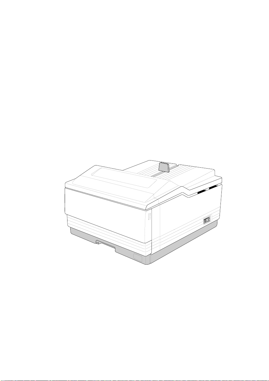
Printer Overview
The QMS 860 Print System (fig. 1.1)
■ Prints 8 pages per minute (letter/A4 paper size) and is the
highest quality 600 x 600 print resolution desktop printer
available with 11" x 17" print capability .
■ Is the most powerful printer in its class, offering the unique
QMS Crown multitasking operating system features,
superior performance, extensive connectivity,
upgradabilit y, and flexib le emul ation support.
■ Provides sc alable, rotatabl e fonts for text and graph ics.
Chapter 1
Fig. 1.1 QMS 860 P rint Syste m
Introduction 1-1
Page 18

Chapter 1
Features
The major features of the QMS 860 Print System are list ed below:
■ Exceptional print quality
Produces 8 pages per minute (ppm) of high-quality
letter/A4 output at 600 x 600 print resolution. The QMS
860 Print System is a desktop printer with
multiple-resolution capability. The 600 x 600 print
resolution provides smooth dense blacks, fine li nes, quality
halftones, and sharp images—excellent for high-quality
photo reproductions.
■ 11" x 17"/A3 output at 600 dpi
Provides the frequently requested 11" x 17"/A3 feature
with high-qualit y 600 dp i output .
■ PostScri pt Level 2 page description languag e capability
Allows you to take full advantage of your printer’s high
print resolution. PostScript Level 2 capabilities are
provided in the QMS 860 Print Syst em via the QMS L evel
2 page description language, a program which is
compatible with Adobe’s PostScript Level 2 language
while providing additional capabilities. QMS Level 2
supports extensive graphics capabilities to control the
appearance of text, geometric shapes and images, and
improves memory and resource management.
■ Emulation Sensing Processor (ESP) Technolog y
Allows your printer to recognize and switch to any
incoming printer emulation loaded on the printer. When
your printer is in ESP mode, you can easily print
PostScript, HP PCL 4, or HP-GL documents.
1-2 Introduction
Page 19

Chapter 1
■ Simultaneous Interface Operation (SIO)
Gives you the ability to have more than one computer
printing to the printer simultaneously. Although many
other printers have multiple interface ports and
automatic ally designate a “hot port,” only one port act ively
receives data at a time. Your QMS 860 Print System is
unique because SIO allows all three interface
ports—AppleTalk, parallel, and serial—to be active and to
receive data at the same time.
You can have more than one computer printing to the
printer. Each interface has an input buffer (which may be
expanded with additional memory) that receives data
while another interface is being used to print. See chapter
3, the “Simultaneous Interface Operation (SIO)” section,
for more information.
The multiple interfaces let you connect to any IBM PC
compatible or Macint osh . The printer als o works in man y
mainframe computer and mini compu ter environm ents .
■ Crown Architecture
Uses the QMS Crown multitasking operating system that
provides faster processing speeds, networking capability,
and higher printer performance while maintaining
outstandin g print quali ty .
■ 3 resident emulations
Supports printi ng in HP PCL 4, HP-GL 7475A/7550A, and
PostScript Level 1 compatibility mode and PostScript
Level 2 emulations.
Introduction 1-3
Page 20

Chapter 1
■ RISC-based Intel controller
Produces outstanding print quality and increases
processing speed. The 80960CA RISC microprocessor
operates at a clock speed of 2 5 Mhz and produces fast
first-page-out performance.
■ 39 resident fonts for Pos tSc ript emulat ion printing
Includes 12 typeface families that contain 39 different
fonts. All typeface families have multilingual character
sets.
■ 12 megabytes (MB) of resident RAM (Random Access
Memory) upgradable to 32 MB and 4 MB of ROM
(Read-Only Memory)
Allows you to expand your printer’s memory. Additional
RAM provides room for downloading and caching fonts,
and it increases the printer’s buffer (are a where data sent
from the computer is stored). Large data-intensive files can
be sent to the printer, freeing the host for other tasks. Your
printer’s ROM includ es 2 M B of system and 2 M B of font
memory.
■ Flexible paper handling
Supports paper in 12 different sizes (11" x 17"/A3,
legal/B4, letter/A4, A5, B5, A6, B6, executive, and
universal). The printer supports print media in sizes
ranging f rom 3.9" to 11.7" (101 m m to 297 mm) wide, and
from 5.8" to 17" (1 47 mm to 43 2 mm) l ong.
■ Optional 250 -she et or 500-sheet paper cassette
Increases the printer’s paper feed capacity. Your printer
comes standard with two 250-sheet paper cassettes:
letter/A4 and 11 " x 17"/A3. You can inst all only one paper
cassette at a time in the printer unless you purchase the
1-4 Introduction
Page 21

Chapter 1
optional paper feeder that allows you to install dual paper
cassettes, increasing paper feed capacity to 600 sheets
(including the multipurpose tray). Attaching an optional
cassette supporter to the paper f eeder allows you to install
a 500-sheet paper cassette, increasing paper feed capacity
to 850 sheets (including the multi purpo se tray).
■ Optional font and emulat ion cards
Increase the printer’s functionality. Extra fonts allow you
to create more distinctive documents. Emulations allow
you to print documents created in a wide range of printer
languages. Fonts (such as the ProCollection for the HP
emulation on your printer) and printer emulations are
contained on small printer circuit boards called cards.
These cards can be plugged i nto the slo ts on t he ri ght side
of the printer under the output tray. Contact your QMS
vendor for a complete list of avai lable cards.
■ Optional securit y card
Restricts printer Configu ration menu access to users with
valid passwords.
■ Optional netwo rk interface
Attaches you r print er to other network interfaces, such as
Ethernet and Token-Ring. These interfaces support the
DECnet, TCP/IP, and Novell NetWare protocol. An
additional interface provides greater flexibility and fast
data transfer when working in complex network
environments.
■ Hard disk expandability
Provides hard disk storage for a cache of character
bitmaps, downloaded outline fonts, and other files. The
Introduction 1-5
Page 22

Chapter 1
resident 25-pin SCSI interface port allows up to 7 external
hard disk drives to be attached to the printer.
■ Convenient cont rol panel operation
Provides a control panel to quickly configure the printer
for your printing needs. The 2-line (16 character-per-line)
panel displays status and error messages in a user-selected
language (English, French, Sp an ish, or German).
About the Documentation
The documentation provides a window into the many capabilities
of your printer. The more famil iar you are with the documentati on,
the easier it will be for you to achieve the results you want from
your printer.
Standard Product Documentation
The following section gives you an overview of the standard
product documentati on t hat comes wi th your print er:
■ QMS 860 Print System User’s Guid e
You’re now looking at your detailed guide to installing and
using your printer. Refer to it as you unpack and set up
your printer, connect it to a host, configure it through the
control panel, replace print media, and maintain and
troubleshoot the printer. The “Ab out This Manual” section
later in this chapter, details the contents of t he user’s guide.
■ QMS 860 Print System Cont rol Panel Gui d e
Keep this fold-out card near your printer so you can
quickly get to it when you need a guide to the control panel
or Configuration m enu. The card lists Configu ration menu
1-6 Introduction
Page 23

Chapter 1
options and identifies control panel indicators and keys.
For a detailed discussion of the information found on the
Control Panel Guide, see chapter 4, “Printer
Configuration ,” in this user’s guide.
■ QMS Crown Network No tes
Refer to this manual for tips on using your QMS 860
printer on a network. It discusses 3Com 3+Open, Banyan
VINES, LAN Manager-based LANs, Novell NetWare,
TCP/IP, UNIX, and VMS/DECnet. In most cases, only
advanced network users and system administrators need
this information.
■ PS Executive Series Utilities
Refer to this documentation as you install and use the PS
Executive Series Utilities software that accompanies your
printer. The PS Executive Series Utilities were designed
specifically for QMS printers. You install this software on
your host and use its user friendly utility programs to
access Macintosh screen fonts, print PC screens, name
your printer, download fonts and emulations, and print
sample files that demonstrate some of your printer’s
capabilities. It includes printer description files required
by your Windows driver and by various applications.A
Windows 3.x driver is also included wit h this soft ware.
■ Printer Optio n Documentation
If you purchased a printer option (for example, a network
interface), you may have received separate document ation
for it. See chapter 8 (“Print e r Optio ns”) o f t his manual for
additional op tion informati on.
Introduction 1-7
Page 24

Chapter 1
Optional Purchase Documentation
The following manuals are optional purchases and are included
with your printer only if you ordered them. (If you did not order
them and decide you want them, you can obtain them from your
QMS vendor.)
■ QMS Crown Document Option Commands (optional
purchase)
This is a reference manual that lists and explains Document
Option Commands (DOCs), which provide another way to
control the printer. DOCs are software codes you insert
into documents to enable printer features that cannot be
accessed by your application or your page description
language. Printer command languages (PostScript, HP
PCL, and HP-GL) typically differ in the way they access
and use printer features and capabilities.
Using QMS DOC, you can develop one driver to support
all languages and emulations for your printer. Also, you
can use host network management software to create
customized network printer queues fo r all users connected
to the printer. In most cases, only advanced users and
system admini strators need this information . See appendix
E, “Document Option Commands,” for a list of the DOC
commands support ed on the QMS 860 print er.
■ QMS Crown II Technical Reference Manual (optional
purchase)
This manual provides advanced technical information,
including information on communication protocols,
HP-GL emulation, and PostScript emulation. In most
cases, only advanced users and system adminis trators need
to access this information.
1-8 Introduction
Page 25

Related Documentation
Don’t forget that your application documentation, your host
operating system do cumentation, and your net work documentatio n
all contain useful printing information. See appendix D, “QMS
Customer Support,” to find out how to use the modem or fax
machine to access information on QMS printers.
About This Manual
This user’s guide provides information on how to install, operate,
and maintain the QMS 860 Print System. Each chapter begins with
highlights of its contents. The appendixes contain supplementary
information, the glossary defines printing and computing terms,
and the index helps you to locate specific topi cs quickl y.
Contents
Chapter 1
■ Chapt er 1 - Introducti on
Provides an overview of the printer’s features and the
documentation.
■ Chapt er 2 - Printer Installation
Provides information on selecting a printer location and
explains how to unpack and inst all yo ur print er.
■ Chapter 3 - Printer-Host Interface
Provides information about Simultaneous Interface
Operation (SIO) and Emulation Sensing Processor (ESP)
technology, and explains how to connect to an Apple
Mackintosh or an IBM PC or compatible comput e r.
Introduction 1-9
Page 26

Chapter 1
■ Chapter 4 - Printer Configura tion
Describes how to operate the control panel and how to use
the menu to configure the printer.
■ Chapt er 5 - Daily Opera tion s
Provides information about printing on paper and
transparencies, loading paper, clearing media jams, and
canceling and ending print jobs.
■ Chapter 6 - Print Quality
Provides informat ion on how to impro ve the print qualit y.
■ Chapter 7 - Professional Printi ng
Provides information on typefaces and page design.
■ Chapt er 8 - Printer Options
Explains how to install o ptional print e r hardware, such as
the paper cassette, paper feeder, cassette supporter, font
and emulation cards, security cards, and external hard
disks. The installation process for SIMM upgrades and
network interfaces is also described although this
installati on should be performed only by a qualified QMS
service technician.
■ Chapt er 9 - Troublesh ootin g
Provides paper jam prevention tips, lists printer error
messages, outlines printer and print quality problems and
solutions, and describes how to place a service call.
■ Appendix A - Cable Pi no uts
Provides the recommended pinouts for AppleTalk,
parallel, serial, IBM PC/XT, and IBM PC/AT cables.
1-10 Introduction
Page 27

Chapter 1
■ Appendix B - Technical Specifi cat ions
Provides printer specifications and lists consumable
supplies and repla cement parts.
■ Appendix C - Character Encodin g Tables
Provides character location tables for the printer’s typeface
families.
■ Appendix D - QMS Customer Support
Provides product sal es and support telephone num bers and
describes how to communicate with QMS through the
QMS Bulletin Board, CompuServe, and Q-FAX.
■ Appendix E - Document Op tion Commands
Lists the Document Option Command s (DOC) supported
by your printer.
■ Appendix F - Addition al Technical In forma tion
Explains how to use the End Job Mode feature, provides
advanced information on configuring memory, describes
how PS protocol operates, and provides the equation for
converting HP-GL emulat ion pen colors to grayscal es.
■ Appendix G - Manu al Noti ces
Contains the manual notices, regulatory statements, and
colophon.
■ Glossary
Defines important printi ng and computi ng terms.
Introduction 1-11
Page 28

Chapter 1
Conventions
The following typographic conventions are used throughout this
manual:
Mixed-Case
Courier
Mixed-Case
Italic
Courier
UPPERCASE
COURIER
lowercase bold PostScript operat ors and DOS com mand s
lowercase italic Variable inform at io n in text and PostSc rip t varia bles
UPPERCASE File and utility names
↵ Press the Enter key (PC) or Retur n key (Mac kin tosh )
^ Press and hold down the Ctrl key (PC)
Text you type, and messages and information
displaye d on th e scr ee n
Variable text you type; replace the italicized word(s)
with inform a tion specific to your pri nt er or comput er
Informatio n disp layed in the print er messa ge windo w
NOTE: Notes contain tips, extra information, or important
information that deserves emphasis or reiteration.
CAUTION: Cautions present information that you need to know
to avoid equipment d amage, process failure, or extreme annoy ance.
WARNING!
Warnings indicate the possibility of personal injury if a specific procedure is not performed exactly as described in the manual.
1-12 Introduction
♦
Page 29

Printer Instal latio n
Chap ter highlight s:
■ Selecting your printer’s locati on
■ Unpacking your printer
■ Installing your printer
Chapter 2
Page 30

Page 31

Selecting Your Printer ’s Locati o n
Your QMS 860 Print System operates in almost any computing
environment. However, when selecti ng your printer’s location, use
the guidelines in the “Location Requirements” and “Power
Requirements” section s of this chapter.
Location Requirements
Your printer’s locations shoul d
■ Be away from cooling sources, heating sources, extreme
temperature changes, direct sunlight, excessive dust, and
corrosive chemicals or vapors.
■ Be away from any strong electromagnetic field (such as
that created by an air condi tioner) and excessive vibration.
■ Have a temperature range of 50° F (10° C) to 90° F
(32.5° C).
Chapter 2
■ Have a relative humidity range of 20% to 80%.
■ Be level and capable of supporting the printer weight,
which is about 50 lbs (22.68 kg) for the printer onl y.
■ Be located an appropriate distance from the host computer,
based on your o perating environ ment—6 f eet (1.8 met ers)
or less for parallel connection or 25 feet (7.5 meters) or
less for a serial connection.
■ Be well ventilated. Leave space on each side of the printer
for adequate ventilation.
Printer Installation 2-1
Page 32

Chapter 2
■ Have enough space (with less than .04"/1 mm degree
slope) to hold the four printer legs and have enough space
in front of the printer for you to open the front cover, to
access th e multipurpose tray, and to slide out the paper
cassette. Figure 2.1 shows your printer with the 11" x
17"/A3 paper cassette installed and enough room to
remove and load the paper cassette.
3.4"(85mm)
25.4"(664mm)
3.5"(90mm)
Fig. 2.1 Space Requirements
3.9"(100mm)
40"(1016mm)
2-2 Printer Installation
Page 33

Power Requirements
Your printer requires a properly grounded AC outlet with a power
range of ± 10 % of the rated voltage. Nois e-generating equipment
should not be connected t o the sam e electrical o utlet as the print er.
The recommended frequency is 50/60 Hz ±2 Hz.
CAUTION: The supplied power cord is equipped with a 3-wire
grounding plug, for safety purposes. Connect the plug to the proper
grounding-typ e po w er out let.
Unpacking the Printer
Use the following procedure to unpack your printer. The packing
materials—cardboard, Styrofoam, tape, and shipping
spacers—that protect your printer during shipment must be
removed.
Chapter 2
You may want to save the packing materials in case you ever have
to move or ship the printer to a new loc atio n.
WARNING!
not attempt to lift it by yourself.
ACHTUNG!
niemals, das Gerät alleine anzuheben od e r zu tragen .
CAUTION: If you turn on the printer before all packing materials
are removed, you may damage the printer.
1. Remove everything except the printer from the shipping
carton.
Printer Installation 2-3
The printer weighs about 50 lbs (22.68 kg). Do
Der Drucker wiegt ca 23 kg; bitte versuchen Sie
Page 34

Chapter 2
2. Lift the printer o ut of the shippin g carton. The printer is heavy,
3. Remove the tape from the print er body.
4. Open the multipurpos e tray using both hands (fig. 2.2).
so two people sh ould be availab le to lift it. Hold the printer by
the carrying grips located on the bottom of the printer.
Fig. 2.2 Open the Mult ipurpose Tray
2-4 Printer Installation
Page 35

Chapter 2
5. Push up on the release button and open the printer’s front
cover (fig. 2.3).
Release Button
Fig. 2.3 Open the Front Cover
Printer Installation 2-5
Page 36

Chapter 2
6. Remove the two orange shipping spacers from inside the
printer (fig. 2.4).
•
cette cale.cette cale.
• Enlever
this spacer.this spacer.
• Remove• Remove
Fig. 2.4 Remove t he Shippi ng S pa cers
•
cette cale.cette cale.
• Enlever• Enlever
this spacer.this spacer.
• Remove• Remove
7. Remove the packing m aterials from inside th e paper cassette.
2-6 Printer Installation
Page 37

Checking Shipment Conte nts
Your shipment consi sts of the foll owin g items:
■ QMS 860 Print S yst e m
■ 250-sheet 11" x 17" or A3 paper cassette
■ 250-sheet letter or A4 paper cassette
■ Rear cassette cover
■ Power cord
■ Warranty card
■ Toner cartridge
■ QMS 860 Print System User’s Guide and bin d er
■ QMS 860 Print System Cont rol Panel Gui d e
■ QMS Crown Netw ork No tes
Chapter 2
■ PS Executive Series Uti lities docum entation and softw are
■ Dataproducts (short-line only) adapter kit (boxed
separately, if ordered)
Make sure that all items are included in your shipment before
installi ng your printer. If any items are missing or damaged , contact
your QMS vendor. See appendix D, “QMS Customer Su pport,” for
product sales and support informati on.
Printer Installation 2-7
Page 38

Chapter 2
Completing QMS Pr oduct Registr atio n
Register your QMS product. In th e US call QMS to ll -free at (800)
637-8049. In ot her countries, refer to appendix D, “QMS C ustomer
Support,” for the appropriate telephone numb er.
Please take a few minutes to call. Your input helps us to continue
developing new products to address your dynami c print ing needs.
Installing Y our Printer
Complete all printer installation tasks (installing the toner
cartridge, instal ling and loadi ng the paper cassett e, connecti ng the
power cord, and printing the start-up page) before installing any
options.
Installing the Toner Cartridge
The toner cartridge contains the toner and photosensitive drum
needed to operate the laser printer. You may purchase additional
cartridges from your QMS vendor.
NOTE: The toner cartridge is sensitive to bright light. Do not
remove the cartridge from i ts protective bag u ntil you are
ready to instal l it.
Keep the toner cartridge away from your computer
system. The magnets in the cartridge can damage data,
particularly on your flopp y disks.
1. Lift the toner cartridge out of its shipping carton, open the
aluminum protecti ve bag, and remove the cartridge.
2-8 Printer Installation
Page 39

Chapter 2
2. Place the cartridge on a flat, stable surface. Then remove the
black protective sheet (fig. 2.5) and discard it.
Fig. 2.5 Remove the Protective Sheet
Printer Installation 2-9
Page 40

Chapter 2
3. Hold the cartridge with both hands, and gently rock it from
side to side five or six times to distri but e the toner (fig. 2.6).
Fig. 2.6 Distribute the Toner
2-10 Printer Installation
Page 41

Chapter 2
4. Hold the cartridge in place with one hand , and using your other
hand grasp the orange tab on the right side of the tape seal.
Keep the cartridge parallel with the flat surface and pull the
orange tab (26.4"/67 cm) straight out (fig. 2.7). Discard the
orange tab and tape seal.
Tape Seal
Fig. 2.7 Remove t he Ta pe Seal
Printer Installation 2-11
Page 42

Chapter 2
5. Grasp the green tabs on the toner cartridge and place the
cartridge on the rails insi de the print e r (fig. 2.8).
Fig. 2.8 Place Toner Cartr id ge on Rai ls
2-12 Printer Installation
Page 43

Chapter 2
6. Lift the green tabs slight ly and slide the cartridge straight back
into the printe r until it is firmly seated (fig. 2.9).
Fig. 2.9 Install the To ner Cartrid ge
7. Close the front cover and close the multipurpose tray (if it is
not being used).
NOTE: When the toner cartridge is installed and the printer’s
front cover is only halfway opened or c losed, the drum
protective shutt ers open and the drum surface is exposed
to light. This may deteriorate the drum and reduce print
quality.
Printer Installation 2-13
Page 44

Chapter 2
Loading the 250-Sheet Paper Cassette
The QMS 860 Print System comes standard with two 250-sheet
paper cassettes (letter/A4 and 11" x 17"/A3). Load paper in either
250-sheet paper cassette as follows .
NOTE: Use t he paper size that matches the paper cassette size.
The paper cassette sends a paper size signal to the
controller when the cassette is inserted into the printer.
1. Align the paper stack on a flat surface.
2. Insert the paper stack into the cass ette s o that i t li es flat, does
not exceed the top limit mark (fig. 2.10), and rests under the
retaining clips. The cassette holds about 250 sheets of 20
pound (75 g/m
2)
paper.
Top Limit
Bottom
Limit
Fig. 2.10 Load the Paper
2-14 Printer Installation
Page 45

Chapter 2
3. Insert the paper cassette into the paper cassette inst allation slot
(fig. 2.11).
Fig. 2.11 Insert the Paper Cassette
Printer Installation 2-15
Page 46

Chapter 2
4. Push the filled paper cassette straight into the instal lation slot
until it is firmly seated (fig. 2.12).
Fig. 2.12 Seat the P aper Cass et te
2-16 Printer Installation
Page 47

Chapter 2
5. Adjust the paper stop to fit the paper size (fig. 2.13). The
printer delivers you r output, print-si de down, to the output tray
at the top of the printer. The paper stop keeps the paper
positio ned in the outp ut t ray.
Fig. 2.13 Adjust the Paper Stop
Printer Installation 2-17
Page 48

Chapter 2
NOTE: If using the 11" x 17"/A3 or the optional legal/B4 paper
cassette. Place the rear cassette cover on the end of the
cassette at the rear of the pri nter (fig. 2.1 4).
Rear Cassette
Cover
Fig. 2.14 Attach the Rear Cassette Cover
2-18 Printer Installation
Page 49

Connecting the Power Cord
The power cord connector is located at the rear of the printer. The
power switch is located at the low er right of the prin ter.
CAUTION: Make sure that the printer power switch is turned off
(the O is pressed down).
1. Align the power cord with the connector on the rear of the
printer, and plu g the power cord into the con nector (fig. 2.15).
Chapter 2
Fig. 2.15 Connect the Power Cord
2. Connect the opposi te end of the power cord t o a grounded AC
outlet.
3. Turn on the printer (press | down). After a brief warm-up,
maximum 2 minutes, the prin ter produces a start-up page.
Printer Installation 2-19
Page 50

Chapter 2
Printing a Start-up Page
When you turn on the printer, a start-up page prints. This page gives
you an overview of your QMS 860 Print System.
Information printed on the start-up page follows :
■ Printer product name
■ Cumulati ve num be r of printed sheets
■ Amount of resident R AM (in by tes)
■ Number of typefaces in ROM
■ Standard interfaces, optional network interfaces,
emulation modes, and printer communication protocol
information
■ Software version number
■ Firmware version numb er
If the start-up page prints with all the start-up page information,
and the print quality is good, go to chapter 3, “Printer-Host
Interface.”
Otherwise, see chapter 9, “Troubl eshooting,” for more informatio n
on printing a start-up page.
WARNING!
Turn the printer off and unplug the power cord
before checking for correct printer installatio n.
ACHTUNG!
Schalten Sie bitte den Drucker aus und ziehen
Sie auch den Netzstecker heraus, bevor Sie die korrekte Installation des Druckers überprü f en.
2-20 Printer Installation
Page 51

Chapter 2
Enabling/Disabling the Start-up Page
Save time and sup pli es by d isabl in g th e start-up p ag e. The syst em
automatically enables the start-up page t o p rint when the printe r i s
turned on.
The start-up page contains information that Customer Technical
Support needs to solve your printer problems. If you only need a
start-up page occasionall y, use the PS Executive Series Ut ilities or
the printer control panel to print a status page instead of a st art-up
page. See the “Printing a Status Page” section of this chapter, for
more information on printing a status page. You can disable the
start-up page in two different ways:
1. Use the PS Executive Series Utilities. See the PS Executive
Series Utili ties manual for more informatio n.
2. Use the printer control panel.
How to Enable/Disab le the S tart-u p Page
Press the control panel keys in the order listed in the following
instructions. The printer responds by displaying a status message
in the message window. You may need to press the Next key one
or more times to advance th rough t he lis t of selecti ons or opt io ns.
Control
Panel Key s
ONLINE/
OFFLINE
MENU CONFIGURATION
NEXT CONFIGURATION
Printer Installation 2-21
Message Window Printer Response
IDLE Turns off the ind icat or.
Accesses the Configura-
OPERATOR CONTROL
ADMINISTRATION
tion men u.
Advances to the Configuration / Administration
menu.
Page 52

Chapter 2
SELECT
and NEXT
ADMINISTRATION
STARTUP OPTIONS
Accesses the Administration menu and advances to
Administration / Startup
Options.
SELECT STARTUP OPTIONS
DO START PAGE
SELECT
and NEXT
DO START PAGE
OPTION
Accesses Startup Options
and Do Start Page displa ys.
Accesses Do Start Page
and advances to the Do
Start Pag e option . OPTION
is either YES or NO, depending on whether you
want to disable or enable
the start -up pa ge .
SELECT OPTION
IS SELECTED
STARTUP OPTIONS
Confirms that the Do Start
Page optio n is selec te d.
Returns to Do St art Page .
DO START PAGE
ONLINE/
OFFLINE
NEXT SAVE CHANGES?
SAVE CHANGES?
NO
YES
Prompts you to save
changes.
Advances to the next Save
Changes opt ion .
SELECT IDLE Finishes printing any print
jobs in process, saves
changes, and i dles or reinitial izes t he print e r .
ONLINE/
OFFLINE
IDLE Turns on the indicator and
puts the printer in a ready
state.
2-22 Printer Installation
♦
Page 53

Printer-Host Interface
Chap ter highlight s:
■ Simultaneous Interface Operation (SIO)
■ Emulation Sensing Processor (ESP ) technol ogy
■ Connecting via the Appl eTalk port
■ Connecting vi a the pa rallel port
■ Connecting via the se rial port
Chapter 3
Page 54

Page 55

Introduction
Interface is the point at which two elements connect so they can
work together. Printer-host interface is the way a printer conn ects
to and works with a host (for example, a microcomputer,
minicompu ter, mainframe computer, or a network), and it in volves
both hardware and software. The way your printer interfaces with
a host depends on many things, including host type, host ports
available, interface cabling, application software, printer
emulations, and printer drivers.
This chapter first explains your printer’s Simultaneous Interface
Operation (SIO) and Emulation Sensing Processor (ESP)
technology. Both of these resident features enhance printer-host
interface. Then this chapter describes how to connect a host to the
printer’s AppleTalk, parallel, or serial port, and test the
communic atio n on that port.
Chapter 3
Optional Network Inter fac es
In addition to the three standard in terfaces—AppleTalk, parallel,
and serial—the QMS 860 Print System has the option of using
another network i nterface, such as DECnet, TCP/IP, and EtherTalk
on Ethernet networks, and Novell NetWare on Ethernet and
Token-Ring networks. This additional interface option allows
greater flexibility when working in a complex network
environment. See you r QMS vendor for a list of availab le network
interfaces.
If you have purchased an optional network interface for the printer,
see chapter 8, “Printer Options,” for installation instructions, and
see your network and your interface kit documentation for
Printer-Host Interface 3-1
Page 56

Chapter 3
additional information. See also QMS Crown Network Notes,
which came with your printer.
Simultaneous Inter fa ce Ope ra tio n (SIO)
Simultaneous Interface Operation (SIO), a standard feature of
QMS Crown architect u re, enables your QMS 860 Print System t o
communicate simultaneously with hosts through the AppleTalk,
parallel, serial, and optional network interface (if installed) ports.
In other words, SIO allows you to have more than one host
communicatin g with the printer at one time. These port s are located
on the interface panel on the back of the printer and are labeled (fig.
3.1).
SCSI
PARALLEL
Fig. 3.1 The QMS 860 Print System Interface Ports
APPLETALK
SERIAL
OPTIONAL I/O
NOTE: The printer’s SCSI port, also located on the interface
panel, is used to connect up to seven optional hard d isk s
to the printer. It is covered by a metal bracket so it is not
confused with the serial port. This metal bracket needs to
be removed before installing a SCSI drive.
3-2 Printer-Host Interface
Page 57

ESP Technology
ESP technology is another standard feature of QMS Crown
architecture. ESP technology, which works with most popular
commercially available applications, uses a form of artificial
intelligence to anal yze incoming file data and select the appropriate
printer emulation (for example, PostScript emulation, HP-GL
emulation, HP-PCL emulation or another option al emulation) from
those install ed on th e printer.
The print job is processed without the user having to change printer
switch settings or send software commands to accommodate
different printer emulations.
When your printer is in ESP mode, you can easily print files
prepared for a PostScript printer, an HP LaserJet, or an HP-GL
plotter. The file prints correctly as long as it begins with the
traditional Post Script or HP-GL commands for such it ems as page
formats and job parameters (number of copies, page margins,
fonts).
Chapter 3
The QMS 860 Print System prints almost any file sent in a language
ESP technology understands, wh ether you have one, two, or more
hosts, and whether you are communicating through a AppleTalk,
parallel, serial, or optional network interface. Most users never
have to change from ESP mode to another mode.
These are a few of the many applications that have been
successfully tested in ESP mode: Adobe Illustrator, Aldus
FreeHand, Aldus PageMaker, AutoCAD, DisplayWrite, Dreams,
Harvard Graphics, Label Matrix, Lotus 1-2-3, Lotus Manuscript,
Microsoft Excel, Microsoft Windows and all Windows
applications, Microsoft Word, MultiMate, PowerPoint, PSPlot,
Printer-Host Interface 3-3
Page 58

Chapter 3
Sprint, SuperPaint, Ventura Publisher, WingZ, WordPerfect, and
WordStar.
Communication Modes
You can either allow your printer to operat e in its default ESP mode
or configure its ports to accept jobs in only a particular emulatio n
mode (for example, PostScript emulation only, HP PCL only, or
HP-GL emulation only).
Generally, it is best to keep your printer in ESP mode. Since ESP
mode is the factory default, all you have to do to use it initially is
connect your host and printer and th en send a file.
If you do want to reconfigure the interface ports for specific
emulations (or if you need to return the printer to ESP mode), the
easiest way is to use the printer’s control panel (the
Administration/Communications menu). Configuring the printer
through the control panel is described in chapter 4, “Printer
Configuration” (and is outlined on your Co ntr ol Panel Guid e).
You can also use PostScript operators to reconfigure print er ports.
The QMS Crown Technical Reference Manual, which is an
optional purchase available from your QMS vendor, contains
information about PostScript operators.
NOTE: We recommend changing printer emulati ons only on the
serial and parallel ports. The AppleTalk port supports
only PostScrip t emulation.
3-4 Printer-Host Interface
Page 59

Connecting via the AppleTalk Port
Connecting to the LocalTalk port involves basically three steps:
assembling the proper interface cabling (use a LocalTalk-type kit
such as Farallon’s PhoneNET, available from your QMS vendor),
making the connection, and making sure the necessary printing
files are installed on the Macintosh
The AppleTalk port is used to print if
■ Your host is any member of the Apple Macintosh famil y,
such as the Macintosh SE, II, IIci, IIfx, IIcx, or Quadra.
The instructions in this chapter explain how to connect a
Macint osh t o the QMS 860 Print Syst em .
■ Your host is an IBM PC or compatible microcomputer,
workstation, minicomputer, or mainframe computer that
connects through a print network (such as TOPS or
AppleShare) using LocalTalk-typ e connectors and boxes.
If you are connecting to a host such as these, you may need
additional hardware or software. See your host or network
documentati on for details specific to your setup .
Chapter 3
Macintosh Interface Cabling
To connect your printer to a Macintosh (fig. 3.2), you must have
two PhoneNET-type transformer boxes: one with a DIN-8
connector for the printer port and one with a DIN-8 connector for
the Macintosh port. You also need an RJ11 (telephone) cable and
enough terminating resistors to close any open sockets left in the
transformer boxes after the connection is made. (You need two
terminating resistors if you are connecting the printer to a single
Macintosh.)
Printer-Host Interface 3-5
Page 60

Chapter 3
Your PhoneNET and Macintosh documentation contain further
information on AppleTalk networks and t he p roper termi nati on of
the transformer boxes.
Host
DIN-8 Female Port
DIN-8 Male Connector DIN-8 Male Connector
Transformer Boxes
RJ11 Cable
Terminating Resistors
Fig. 3.2 Printer Interf ac e Cable s and Conne cti ons
Printer
DIN-8 Female Port
Making the Connection
Use the following procedure to connect your print er to the host.
CAUTION: Turn off both the printer and the host before making
the connection.
1. Connect the DIN-8 connector from one transform er box to the
printer’s AppleTalk port.
2. Plug the DIN-8 connector from the other tr ansformer box into
the Macint osh pri nter port.
3. Plug one end of the RJ11 cable int o the transforme r box at the
printer and the other en d of the c able int o the tr ansformer box
at the host.
3-6 Printer-Host Interface
Page 61

4. Insert terminating resistors into any open sockets in the
connector boxes. This ensures proper communication and
helps speed up transmission.
5. Turn on the printer. A start-up page should print if it has not
been disabled.
Macintosh Printing Software
Once the Macintosh and printer are physically connected by the
LocalTalk cable, you must make sure the necessary printer
software files (for example, drivers and printer description files)
are installed on the Macintosh so it can communicate with the
printer.
PS Executive Series Utilities
We strongly recommend that yo u now ins tall P S Executi ve Se ries
Utilities that came with your printer because it contains, among
other things
Chapter 3
■ Printer drivers and printer description files required for
printing from many Macintos h applic atio ns
■ Utilities for installing printer-resident screen fonts,
renaming the printer, downloading fonts, and managing
hard disks
■ A Paper Handler utility, which gives Macintosh users
additional paper handlin g capabilities on multit ray printers
■ Font sampl e fi les
The PS Executive Series Utilities documentation explains how to
install and use the program.
Printer-Host Interface 3-7
Page 62

Chapter 3
Macintosh Printer Drivers
A printer driver converts generic commands from applications into
printer-specific commands. You must have a driver designed for
your particular printer to print from your application.
Most Macinto sh applications use the Apple LaserWriter driver that
comes with the Macintosh system software. However, we
recommend installing the LaserWriter driver included in PS
Executive Series Ut ilities because it supports addi tional page sizes
specific to your printer.
If you are adding the printer to an existing network, the printing
software you need is probably already installed on y our Macintosh.
To determine whether you already have the necessary software, do
the following at yo ur Ma cint osh:
1. Choose Cho oser from the Ap ple menu. The Choos er wind ow
is displayed.
2. If a LaserWriter icon appears in the Chooser window, click
the icon to display a list of available printers. Highlight
860 Print System
Chooser window.
QMS
to select your printer; then close the
If a LaserWriter icon does not appear in the Cho oser window,
you must copy the LaserWriter file from PS Executive Series
Utilities onto the System Folder icon on your hard disk or
start-up disk; then close the Chooser window. In order to
install the LaserWriter driver, use the following procedure:
a. Double-click the hard disk or start-up disk icon to display a
window showing the disk cont ents, includi ng the System Fo lder.
b. Insert the PS Executive disk called Drivers in a disk drive and
double-click the disk icon to disp lay a window showing the disk
contents, including Paper Handler. Double-click the Paper
3-8 Printer-Host Interface
Page 63

Chapter 3
Handler icon to display a window containing LaserWriter
(among other things).
c. Copy the LaserWriter file by dragging the icon o nto the Syst em
Folder icon on your hard disk or start-up disk. System 6 users
should have the LaserWriter file located in the System Folder.
System 7 users should have the LaserWriter file located in the
Extensions Fol der within the Syst em Fol der .
NOTE: All Macintosh users on a network must use the same
version of the LaserWriter and Laser Prep files to run
correctly. For example, if the network has a mixture of
LaserWriter 6.0 and 7.0, the printer will experience frequent
reinitializat ion problem s. To check the versi on num ber, sel ect
the LaserWriter icon and then hold down the Command key
and press I. The driver version number appears in the Info
window on th e secon d to last line. LaserWriter 7.xx does not
require a Laser Prep file to work correctly with your printer.
The Laser Prep information is located with in the LaserWriter
driver itself.
Printer Description Files
In addition to LaserWriter and Laser Prep, many Macintosh
applications, including Aldus PageMaker, Aldus FreeHand, Adobe
Separator, and QuarkXPress, use special printer description files.
PS Executive Series Utilities includes these special files, called
APD (Aldus Printer Description), PPD (PostScript Printer
Description), PDX (Printer Description eXtension), and PDF
(Printer Description File). See “Using the Macintosh Utilities” in
the PS Executive Series Utiliti es documentation for detail s.
Adobe Sep ara tor uses the PPD file. You have to tell Separator where the PPD is located on your Macintosh. Check your Adobe documentation for details.
Printer-Host Interface 3-9
Page 64

Chapter 3
QuarkXPress uses t he file called P DF. Each QMS printer model requires its own PDF. You must load the PDF in the same folder as the QuarkXPress application. Check your QuarkXPress documentation for details.
Aldus PageMaker 4.2 and higher use PPD and PDX files. The PDX works in conjunction with the stand ard PPD to expand printer capabilit ies. The PPD and PDX must be placed in the PPDs folder within the Ald us folder in sid e your Sys tem F ol der.
Aldus PageMaker 4.01 and earli er use the APD file. The APD gives PageMaker information specific to your printer type. Different versions of PageMaker require the APD to be installed in different ways. Check your PageMaker documentation for details.
NOTE: In PageMaker 4.0 and higher, if you use these printer
description files and have installed the QMS Paper
Handler, you will not be able to access QMS Paper
Handler features from the default menu. To overc ome
this problem, hold down the Option key when selecting
Print from the File menu and use the Apple Driver
window.
Aldus F r eeH and 3.0 an d hi gh er use PPD and PDX files. The PDX works in conjunction with the standard PPD to expand capabilit ies. The PDX and PPD must be placed in the PPDs folder inside the Aldus folder inside your System Folder.
Aldus Pr ePri nt uses PPD and PDX files. The PDX works in conjunction with the standard PPD to expand capabilities. The PDX and PPD must be pl aced in the PP Ds fo lder inside the Aldu s folder inside yo ur Sys tem Fol d er.
3-10 Printer-Host Interface
Page 65

Chapter 3
If you do not install these files for your printer, you can still print
from the applications using other printer options. However, you
may get some error messages informing you to change the name
of the printer, and you may not have all your printer capabilities
available to you.
Testing Macintosh Communication
You can check that the printer selected in the Chooser and the
Macintosh are communi cating by printin g a directory:
1. Display a disk or folder window.
2. Choose Page Setup from the File menu. Select paper size,
printing orientation, and any other necessary options. Then
select OK.
3. Choose Print Directory or Print Window from the Fil e menu.
A dialog bo x app ears.
4. Select the printi ng options you want; then cl ick OK. If no page
prints, check chapter 9, “Troubleshooti ng.”
Connecting via the Parallel Port
Parallel communication is faster than serial communication, so it
is best if
■ A parallel port is available on your host
■ The host and printer are within 6 feet (approximately 1.8
meters) of each other
■ You print a lot of graphics
Printer-Host Interface 3-11
Page 66

Chapter 3
A parallel cable has a 36-pin male connector on the print er end and
a 25-pin male connector on the host end. This cable is available
from your QMS vendor. A Dataproducts adapter kit (short-line
only) is also available from your QMS vendor. See chapter 8,
“Printer Options ,” for inst all atio n instructions.
CAUTION: If you are connectin g the print er t o a single ho st, turn
off both systems first.
Use the following procedure to connect your printer to your host
via the parallel port:
1. Attach the 36-pin printer end of the cable to the parallel port
on the printer (fig. 3.3); then cl ose th e clips.
Host
25-Pin Female Port
Fig. 3.3 Host and Printer Parallel Interface Ports
Printer
36-Pin Female Port
2. Attach the othe r end of the cable to the host’s paral lel po rt.
3. If necessary, use the printer control panel to set up parallel
communication. The factory default parallel settings are
appropriate for most parallel communications. See chapter 4,
“Printer Configu ration ,” if you need more information.
Testing Parallel Communication
To test communication between your printer and host, first create
a short file that ejects a page from the prin ter. Th en send the file to
the printer.
3-12 Printer-Host Interface
Page 67

Chapter 3
Creating the Test Fil e To create the test file, type the following commands at the DOS prompt (you can use either uppercase or lowercase letters; however, you must type the PostScript showpage operator in lowercase letters). The ↵ symbol means to press the Enter key. To produce the ^D and ^Z, press and hold down the Ctrl key while you type the appropriate lett ers (d and z). These characters signify the end of the file and must always be incl uded.
copy con printest.ps↵
showpage↵
^D^Z↵
Sending the Test File To test parallel communication, type the following com mand at t he DOS prom pt to send the P RINTEST.PS file you just created to the printer:
print printest.ps↵
If prompted for th e nam e of the list device, type
lpt1↵
or type the name of the parallel port that the printer is connected
to.
If the printer and host are communicating, a blank page ejects from
the printer.
If a blank page does not ej ect and you t yped the file correctly, yo u
may want to check your AUTOEXEC.B AT file to see if LPT1 (the
parallel port) is being directed to COM1 (the serial port):
1. If the AUTOEXEC.BAT file contain s the line
MODE LPT1:=COM1:
delete it.
Printer-Host Interface 3-13
Page 68

Chapter 3
2. Then type
MODE LPT1:,,P
in the AUTOEXEC.BAT file so that print jobs are sent until
the printer accepts them.
3. Reboot the host and try th e commun icati on test again.
See chapter 9, “Troubleshooting,” and refer to your DOS
documentation for more info rmati on.
Connecting via the Serial Port
Serial communication is best if
■ A parallel port is not available on your host
■ The host is more than 6 feet (approximately 1.8 meters)
but less than 25 feet (approximately 7.5 meters) from the
printer
■ You want the printer to return info rmati on to the host
The standard serial cable has a 25-pin male (DB-25 ) connector o n
the printer end and either a 9-pin female connector or a 25-pin
female connector on the host. See appendix A for pinouts.
CAUTION: Turn off both the printer and the host before making
the connection.
Use the following procedure to connect your printer to your host
via the serial port:
3-14 Printer-Host Interface
Page 69

Chapter 3
1. Insert the 25-pin male printer end of the cable into th e printer’s
serial port (fig. 3.4); then tighten the screws on the cable to
attach it to the printer.
9-Pin Male Port
Host
Fig. 3.4 Host and Printer Serial Interface Ports
Printer
25-Pin Female Port
2. Plug the other end of the cable into the host’s serial port. On
some hosts, the 25-pin parallel port and t he 25-pin serial port
may look si milar, b ut the parallel port is female and the s erial
port is male.
The following sections, “Testing Serial Communication” and
“Changing Serial Port Settings,” explain how to establish serial
communic ation between the prin ter and the host.
Printer-Host Interface 3-15
Page 70

Chapter 3
Testing Serial Communication
Before you can print to the serial port, the printer, host, and
application must all communicate using the same serial port
settings. If your printer is replacing another prin ter, and if you are
using the same cable to connect it to the host, the host is probably
already configured correctly. However, if the host has not been
connected to a printer before, or if you are using a different cable,
use the information in this section to test the communication
between printer and host.
To test communication between your printer and host, first create
a short file that ejects a page from the printer and then send it to the
printer.
Creating the Test Fil e To create the test file, type the following commands at the DOS prompt (you can use either uppercase or lowercase letters; however, you must type the PostScript showpage operator in lowercase letters). The ↵ symbol means to press the Enter key. To produce the ^D and ^Z, press and hold down the Ctrl key while you type the appropriate lett ers (d and z). These characters signify the end of the file and must always be incl uded.
copy con printest.ps↵
showpage↵
^D^Z↵
Sending the Test File To test serial communication, type this command at the DOS prompt to send the PRINTEST.PS file you just created to the printer:
print printest.ps↵
If prompted for th e nam e of the list device, type
com1↵
3-16 Printer-Host Interface
Page 71

Chapter 3
If the printer and host are communicating, a blank page ejects from
the printer. If a blank page does not eject and you typed the file
correctly, see chapter 9, “Troubleshooting.” You may also want to
check your AUTOEXEC.BAT file in DOS to make sure that the
printer’s serial port settings match those of the PC. Look for a
command line like thi s in your AUTOEXEC.BAT file:
MODE COM1: 9600,N,8,1,P
In this example, the serial port settings are 9600 for baud rate, n
(no) parity, 8 data bits, and 1 stop bit. The p stands for infinite retry.
Now check the start-up page, which prints when you turn on the
printer (unless you disabled it ). This tells you the current serial port
settings for the printer. If the serial settin gs (baud rate, pari ty, data
bits, and stop bits ) sho wn o n the s tart-up page match t hose in y our
AUTOEXEC.BAT file, you need make no further changes. Go to
the section “Special PC Concerns” later in this chapter.
If the printer’s serial port settings are different from your PC’s, you
must make them m atch. Refer to the fol lowing section, “Changin g
Serial Port Set tings,” to do this.
Changing Serial Parameters
Since your printer is configured at the factory for the most typic al
printing environments, the serial parameters in your
AUTOEXEC.BAT file and o n the start-up page sho uld be the same.
However, if they differ, you must configure the printer to use the
serial parameters specified in the AUTOEXEC.BAT file.
Press the control panel keys in the order shown in the following
instructions to change the printer’s serial parameters. The printer
responds by displaying a status message in the message window.
Printer-Host Interface 3-17
Page 72

Chapter 3
You may need to press the Next key one or more times t hrough the
list of selections or options. If you need to change other serial
parameters, refer to chapter 4, “Printer Configuration,” for
complete informati on.
NOTE: The printer must be off line and idle to change printer
How to Access Serial Mode
Control
Panel Key s
configuration.
Message Window Printer Response
ONLINE/
OFFLINE
MENU CONFIGURATION
NEXT CONFIGURATION
SELECT ADMINISTRATION
SELECT COMMUNICATIONS
NEXT COMMUNICATIONS
IDLE Turns off the indicator an d
OPERATOR CONTROL
ADMINISTRATION
COMMUNICATIONS
TIMEOUTS
SERIAL
takes the prin te r off line.
Accesses the Configuration men u.
Advances to the Configuration / Administration
menu.
Accesses the Configuration / Administration menu
and displays Administration / Communications.
Accesses the Administration / Communications
menu and displays Administr ation / Com m unica tions / Timeout s.
Advances through the Administration /Communications menu.
3-18 Printer-Host Interface
Page 73

Chapter 3
SELECT SERIAL
MODE
How to Change the Baud Rate
NEXT SERIAL
BAUD RATE
SELECT BAUD RATE
*9600
NEXT BAUD RATE
RATE
SELECT RATE
IS SELECTED
SERIAL
BAUD RATE
Accesses the Administration / Communications /
Serial menu and displays
the Mode option .
Advances through the Serial options.
Accesses the Baud Rate
option and di splays the currently selecte d ba ud ra te .
Advances through the
Baud Rate options. (RATE
is any Baud Ra te opti on.)
Confirms the se lected baud
rate.
Returns to the Administration / Communications /
Serial menu. If you are
done changing serial parameters, then go to the
“How to Save Changes”
section l ater in this chap te r
for save changes information.
How to Change the Parity
NEXT SERIAL
PARITY
SELECT PARITY
*NONE
Printer-Host Interface 3-19
Advances through the Administr ation / Com m unica tions / Serial menu.
Accesses the Parity option
and displays the currently
selecte d pa rity.
Page 74

Chapter 3
NEXT PARITY
TYPE
SELECT TYPE
IS SELECTED
SERIAL
PARITY
How to Change Data Bits
NEXT SERIAL
DATA BITS
SELECT DATA BITS
8 BITS
Advances through the Parity options. (TYPE is any
parity option.)
Confirms the selected parity.
Returns to the Administration / Communications /
Serial menu. If you are
done changing serial parameters, then go to the
“How to Save Changes”
section l ater in this chap te r
for save changes information.
Advances through the Serial menu.
Accesses the Data Bits option and displays the currently selected data bits.
NEXT DATA BITS
7 BITS
SELECT 7 BITS
IS SELECTED
SERIAL
DATA BITS
3-20 Printer-Host Interface
Advances thro ugh the Da ta
Bits optio ns.
Confirms the selected data
bits.
Returns to the Administration / Communications /
Serial menu. If you are
done changing serial parameters, then go to the
“How to Save Changes”
section l ater in this chap te r
for save changes information.
Page 75

How to Change Stop Bi ts
Chapter 3
NEXT SERIAL
STOP BITS
SELECT STOP BITS
1 BIT
NEXT STOP BITS
2 BITS
SELECT 2 BITS
IS SELECTED
STOP BITS
SERIAL
How to Save Changes
ONLINE/
OFFLINE
SAVE CHANGES?
NO
Advances through the Administr ation / Com m unica tions / Serial menu.
Accesses the Stop Bits option, and displays the currentl y selected sto p bits.
Advances through the Stop
Bits optio ns.
Confirms the selected stop
bits.
Returns to the Administration / Communications /
Serial menu. If you are
done changing serial parameters, then go to the
“How to Save Changes”
section ne xt in this chap te r
for save changes information.
Displays the default Save
Changes opt ion .
NEXT SAVE CHANGES?
YES
SELECT IDLE Finishes printing any print
ONLINE/
OFFLINE
Printer-Host Interface 3-21
IDLE Turns on the indicator and
Advances t hrough the Save
Changes opt ion s.
jobs in process, saves
changes, and i dles or reinitial izes t he print e r .
puts the printer in a ready
state.
Page 76

Chapter 3
To verify the serial parameter changes you just made, turn the
printer off, then back on. Compare the printer’s start-up page to
your AUTOEXEC.BAT file.
Special PC Concerns
PC Printer Drivers
To communicate with your printer, a printer driver that supports
PostScript a nd the QMS 860 Print S ystem must be install ed in y our
application.
A printer driver converts generic printer commands from
applications into printer-specific commands. Many applications
have drivers built in, and you only have to choose a driver from a
menu.
If you already use a PostScript-compatible printer, the driver
defined for that printer will work with your new QM S print er, but
you may not be able to access all of the printer’s features. If your
application does not offer a driver for any QMS printers, you can
use a PostScript driver (if you are working in PostScrip t emul ation
or ESP modes), a LaserJet driver (if you are working in HP PCL
emulation or ESP modes), or a HP-GL 74 75A or 7550 plotter driver
(if you are working in HP-GL emulati on or ESP mo des).
However, if your QMS 860 Print System has features your old
printer did not, such as additional resident fonts , you may want to
install a new driver capable of handling these features. If your
application does not o ffer a multip le-tray print e r driver, it may not
support paper tray selection. Any PostScript printer driver
supporting 11" x 17" output ensures that you get basic printer
functions and 11" x 17" capability. To benefit from all the functions
3-22 Printer-Host Interface
Page 77

Chapter 3
available on your printer, you need to use the QMS 860 Print
System driver.
Sometimes drivers are available from application manufacturers.
Some drivers for QMS printers are also available through the QMS
Corporate Bulletin Board System and through CompuServe; see
appendix D, “QMS Customer Support ,” for informat ion .
NOTE: The QMS 860 printer driver, including the Windows
driver, support all printer supported paper sizes, trays,
and cassettes. Depending on your version of Windows
and your printing environment, you may encounter
printing problems with the Windows driver. If so, use
Microsoft’s Windows driver with the WPD file inclu ded
with the PS Executive Series Utilities. See the PS
Executive Series Utilities documentation for more
information on the WPD file.
PC Screen Fonts
Screen fonts allow you to see on the screen how your document
looks before it is printed. You may be able to obtain PC screen fonts
from your application manu facturer or from QMS’s electroni c fax
system “Q-FAX,” which will fax you a request form to order the
PC screen fonts. (See appendix D, “QMS Customer Support, ” for
information.) However, you can use the printer fonts without
having the corresponding screen fonts.
Printer-Host Interface 3-23
♦
Page 78

Page 79

Printer Co nfig ura ti on
Chap ter highlight s:
■ Printer control panel operation
■ Printer men u structure
Chapter 4
Page 80

Page 81

Introduction
Now that you have your QMS 860 Print S ystem s et up (chapter 2),
connected to a host computer, and ready to print (chapter 3), you
need to learn more about how to control the print er and the printing
process. This chapter describes the pri nter’s menu structure, whi ch
you access through the printer’s control panel . The Control Panel
Guide that came with the print er also contains this informati on, in
summary form. However, you should read this chapter to make
using the Control Panel Guide easier and to become familia r wit h
your printer’s capabiliti es.
Control Panel
The control panel keys allow you to configure the printer through
menu selections that control printer operations. The control panel
LED (light emitting diode) indicators and LCD (liquid crystal
display) message window provide information about the printer
and about the status of print jobs. The first part of this chapter
identifies each control panel part and describes its function. You
should read this section to learn how to use the keys and how to
interpret messages and indicators.
Chapter 4
Menu Structure
The second part of this chapter describes the menu structure and
lists the default for each option. A default is a preset value for the
most common print ing environm ent.
This chapter provides basic pri nter configuration information about
all menu optio ns because most users do not have to use the printer’s
Configuration menu often. The QMS Crown Technical Reference
Printer Configuration 4-1
Page 82

Chapter 4
Manual, which is an optional purchase available from your QMS
vendor, contains mor e extensive configuration info rmation.
NOTE: The Administration / Miscellaneous menu Restore
Defaults option allows you to restore factory defaults.
See the “Administration/Miscellaneous” section of this
chapter for more information on this option.
Printer Control Panel
The control panel (fig. 4.1) consis ts of the following parts:
■ Five indicators that display printer status information,
three print engine indicators that displ ay th e current input
bin, and a message window that provides configuration
and status information.
■ Seven control panel keys (three function keys and four
menu keys) that allow y ou to access frequently used printer
options .
Fig. 4.1 Printer Control Panel
4-2 Printer Configuration
Page 83

Chapter 4
Control Panel Indicators
Five indicators on the control panel display printer status
information:
Flashes when the printer is warming up. Remains on
when the printer is ready to receive a print job and
during pri nter opera tion unle ss an err or is enco untere d.
Lights whe n the pri nter re quires op era tor int erven tion.
This indicator is usually accompanied by a status
message in the message window.
Lights when the printer is receiving data from one or
more of the simultaneo us int er faces.
Lights when the printer is on line and ready to accept
and process new print jobs. Pressing it once takes the
printer off line (the indi cato r is not light ed), makin g the
printer re ad y for confi gur at ion .
Lights when the Configuration menu is accessed and
remains on until the Online/Offl in e key is pressed.
Three indicators on the control panel’s print engine diagram show
the current input bin:
Lights when the multipurpose tray is the current input
bin.
Lights when the lower paper cassette is the current
input bin.
Lights when the optional paper cassette is the current
input bin.
Printer Configuration 4-3
Page 84

Chapter 4
Control Panel Display
The message window provides configuration and status
information.
MESSAGE WINDOW
Displays two lines of text (with 16 characters on each
line) and presents status messages and configuration
menus.
Status messages are displayed by priority. Priority indicates the
severity of the message. The highest priority messag e display s on
the top line. If a message uses only the top line of the display, the
next highest priority message displays on the bottom line.
However, if either message display exceeds one line, only the
highest priorit y messag e is displayed.
When the status associat ed with a display ed message has changed,
the message is cleared from the window and the next highest
priority message is displayed. See chapter 9, “Troubleshooting,”
for a list of the status messages t hat display in the m essage window.
Control Panel Function Keys
The three function keys (Online/Offline, Cancel, and S tat us Page)
access frequently used printer options. The four menu keys (Menu,
Select, Next, and Previous) access the Configuration menu and
select options. Keep in mind that some of the function keys may
be used in combinati on wit h th e menu keys.
4-4 Printer Configuration
Page 85

Chapter 4
NOTE: Always make sure the printer is idle and off line before
making configu ration changes. You must take the pri nter
off line before using the control panel keys (except for
the Online/Offl ine key, Cancel key, and Status Page key).
If the printer is not idle, jobs may be los t.
Online/Offline Key When the printer is on line, the indicator on the key is light ed. Press the k ey once to take the p rinter off lin e (the indicator goes out). Yo u must take the printer off li ne before usin g all other keys except the Cancel key and the Status Page key.
When the printer goes off line, the com munication ports ar e closed,
so no new data is accepted. The engine stops printing when the
printer has finished printing all jobs in process. Although jobs
continue to compile and prin t using the data already received, a job
may be interrupted, causing it to wait for more incoming data
before printing resumes.
When the printer is off line, pressing the Online/Offline key once
places it back on line. The indicator lights, and the printer is once
again ready to accept and process new print jobs.
NOTE: Use the Menu key to stop the print job c ancel or end.
Cancel Key Press this key to cancel a print job or to send an
end-of-job indicator to a print job waiting for incoming data. It is
not necessary to take the printer off line first.
How to Cancel a Print Job
Press the control panel keys in the order shown in the following
instructions to cancel a print job. The printer responds by
displaying a status message in the message window. You may need
to press the Next key one or more times to advance through the list
of selections or optio ns.
Printer Configuration 4-5
Page 86

Chapter 4
Control
Panel Key s
Message Window Printer Response
CANCEL CANCELLING JOB?
YES
CANCEL or
SELECT
YES
IS SELECTED
CANCELLING JOB Cancels the first job in the
IDLE Finishes printing any print
Displays the Cancelling
Job confirmatio n messag e.
Confirms that jobs which
are printing or compiling
data are to be deleted from
the job que ue.
job queue and displays the
Cancelling Job message
unti l the jo b is co mplete ly
removed from the printer.
jobs in process, saves
changes, and i dles or reinitial izes t he print e r .
How To End a Print Job
Press the control panel keys in the order shown in the following
instructions to send an end-of-job indicator. The printer responds
by displaying a status message in the message window. You may
need to press the Next key one or more times to advance through
the list of selections or options.
Control
Panel Key s
CANCEL CANCELLING JOB?
4-6 Printer Configuration
Message Window Printer Response
WAITING FOR INPUT
END JOB?
YES
Displays this message and
accepts an end-o f-j ob indi cator for the cu rrentl y compiling jo b if it is the first job
in the job queue and is
waiting for incoming dat a.
Confirms that print jobs are
to be cancelled.
Page 87

Chapter 4
NEXT or
PREVIOUS
CANCEL or
SELECT
CANCELLING JOB?
END JOB
END JOB
IS SELECTED
IDLE Finishes printing any print
Displays Cancelling Job
End Job c onfirm atio n me ssage.
Confir ms that th e print jobs
waiting for inp ut are ended.
jobs in process, saves
changes, and i dles or reinitial izes t he print e r .
Status Page Key Use the Status Page key to print a page listing the current printer settings. See chapter 5, the “Printing a Status Page” section, for in formation on the status page cont ents. It is not necessary to take the printer off line to print a status page.
How to Print a Status Page
Press the control panel keys in the order shown in the following
instructions to print a status page. The printer responds by
displaying a status message in the message window. You may need
to press the Next key one or more times to advance through the list
of selections or optio ns.
Control Panel Message Window Printer Response
STATUS
PAGE
SELECT YES
Printer Configuration 4-7
PRINT STATUS
YES
IS SELECTED
PRINTING STATUS Prints the st atus pa ge whe n
IDLE Finishes printing any print
Displays Print Status confirmation message.
Confirms that the Status
Page is selected.
the job queue is available
and clears the Printing
Status message.
jobs in process, saves
changes, and i dles or reinitial izes t he print e r .
Page 88

Chapter 4
Control Panel Menu Keys
Use the Menu, Select, Next, and Previous keys to move around the
printer menu. The top line of the message window always di splays
the name of the current menu, and the bot tom line displays the name
of a selection or op tion wi th in that menu . The followi ng d escri bes
how to use the control panel keys to move around the menu:
Control Panel Printer Response
When the printer is on line, the indicator on this key
lights. Press the key once to take the prin ter off line (the
indicator goes out). You must take the printer off line
before going into the control panel menu for all keys
except t he Ca ncel key a nd th e Sta tu s Pa ge key.
Press this key to access the Configuration menu after
the prin ter go es off lin e. W he n cha nging pri nte r set up,
press this key to cancel a change (before pressing the
Select key), to return to a previous menu, or to return
to a previous character when entering character
information.
Press this key to access a menu or to choose a displayed
menu option.
Press this key to advanc e throu gh t he list of select io ns
or options for the current menu. When changing
character information, use this key to advance to the
next choi ce for th e curre nt i nput cha ra ct er.
Press this key to return to the previous selection or
option for the current m enu. W hen cha nging charac te r
information, use this key to return to the previous
choice fo r the curren t in put cha rac te r.
4-8 Printer Configuration
Page 89

Menu Structure
Use the Configuration menu to access printer configuration
selections. The Configuration menu is organized into groups by
logical function. The three functions are Installation, Operator
Control, and Administration (fig. 4.2). The menu allows you to
select a function using the Select key, then another menu appears
that displays the list of selections for that function. Functions are
further divided into logical groups called submenus. In the case
where submenus are needed, the function provides access to the
submenu.
Chapter 4
Idle
Installation
Operator
Passwrd
Copies
Communications
Use Operator
Pwd
Collation
Emulations
Admin
Password
Orientation
Special Pages
Operator Control
Use Admin
Pwd
Inputbin
Startup Options
Chain
Inputbins
Memory
Administration
Multipurpose
Sz
Engine
Miscellaneous
Disk Operations
Fig. 4.2 Configuration Menu
Printer Configuration 4-9
Page 90

Chapter 4
■ Installation
Use this function to establish passwords for the Operator
Control and Admin istration menus. Thi s function displ ays
only when an optional security card is instal led.
■ Operator Control
Use this function to maintain d ocument processing option s
(number of copies, media type, and paper orientation).
These capabilities are usually handled most efficiently
within specific print jobs since each job has its own
requirements. However, if there is no way of specifying
these option s withi n a job, you may do so from the co ntrol
panel.
■ Administ ratio n
Use this function to maintain host computer
communicatio n informati on for selecti ng and confi gurin g
printer emulations, configuring special pages, printing
engine calibration, and configuring hard disks (if
installed).
4-10 Printer Configuration
Page 91

Chapter 4
Accessing the Configuration Menu
Use the menu keys to access the printer Configur ation menu.
How to Access the Configuration Menu
Press the control panel keys in the order shown in the following
instructions to access the Configuration menu. The printer
responds by displaying a status message in the message window.
You may need to press the Next key one or more times to advance
through the lis t of selecti ons or opt io ns.
Control
Panel Key s
Message Window Printer Response
ONLINE/
OFFLINE
MENU CONFIGURATION
IDLE Turns off the ind icat or.
Accesses the Configura-
OPERATOR CONTROL
tion men u.
NOTE: The printer must be off line and idle to change printer
configuration.
Using Passwords
The Operator Control an d Administration men us may be password
protected using an optional security card. If a password is required,
the message window d isplays EN TE R PASS WORD when you use
the Select key to enter the menu. Enter the password or press the
Menu key to return to the menu. Se e chapter 8, “Print e r Options, ”
for more information on security cards.
If an invalid password is entered, the message window flashes
INVA LI D PAS SW OR D fo r three seconds and then retu rns you to
Printer Configuration 4-11
Page 92

Chapter 4
the Configuration menu. If you specify the correct password,
access to the selected menu is granted.
Accessing Selections and Options
Menus list each selection available within a functional group. For
example, in figure 4.3 the Administration menu has a
Communications submenu that has a Parallel selection. The
Parallel/Emulation selection has options, such as ESP, Hexdump,
PCL4, HP -GL, and P ostScript.
Configuration
Installation
❏
Operator Control
❏
Administration
■
Administration
Communications
■
Emulations
❏
Special Pages
❏
Startup Options
❏
Memory
❏
Engine
❏
Miscellaneous
❏
Disk Operations
❏
Administration/
Communications
❏
Timeouts
❏
Serial
Parallel
■
AppleTalk
❏
Communications/
Parallel
❏
Mode
■
Emulation
❏
Min K Spool
❏
Spool Timeout
❏
Data Bits
❏
End Job Mode
Parallel/
Emulation
ESP
Hexdump
PCL4
HPGL
PostScript
Fig. 4.3 Menu Acce ss
How to Select Configuration Menu Options
4-12 Printer Configuration
Page 93

Chapter 4
Press the control panel keys in the order shown in the following
instructions to select Configuration menu options. The printer
responds by displaying a status message in the message window.
The top line of the message window displays the name of the
current menu, and the second line displays the name of the current
selection. You may need to press the Next key one or more times
to advance thro ugh the lis t of selecti ons or opt io ns.
Control
Panel Key s
Message Window Printer Response
ONLINE/
OFFLINE
MENU CONFIGURATION
NEXT CONFIGURATION
SELECT ADMINISTRATION
SELECT COMMUNICATIONS
NEXT COMMUNICATIONS
SELECT PARALLEL
NEXT PARALLEL
IDLE Turns off the ind icat or.
OPERATOR CONTROL
ADMINISTRATION
COMMUNICATIONS
TIMEOUTS
PARALLEL
MODE
EMULATION
Accesses the Configuration men u.
Advances to the Administration menu.
Accesses the Administration menu and displays
Communications.
Accesses the Administration / Communications
menu and Timeouts displays.
Advances to the Administra tio n / Commun ica ti ons
/ Par alle l m e nu
Accesses the Administration / Communications /
Parallel menu and disp la y s
the Mode selection.
Advances to Parallel /
Emulation.
Printer Configuration 4-13
Page 94

Chapter 4
SELECT EMULATION
ESP
PREVIOUS EMULATION
POSTSCRIPT
SELECT POSTSCRIPT
IS SELECTED
PARALLEL
EMULATION
ONLINE/
OFFLINE
or MEN U
NEXT SAVE CHANGES?
SELECT IDLE Finishes printing any print
SAVE CHANGES?
NO
YES
Accesses the E mulation selection and displays the
ESP option.
Advances to the PostScript
option.
Confirms that the PostScript emulation is selected.
Returns to Parallel / Emulation.
Exits from the menu (Online/Offline) or returns to
the previous menu (Menu)
and prompts you to save
changes if changes were
made to configuration values. To ignore changes,
press the Select key and
then press Online/Of fline .
Advances to the next save
changes opt ion.
jobs in process, saves
changes, and i dles or reinitial izes t he print e r .
ONLINE/
OFFLINE
IDLE Turns on the indicator and
puts the printer in a ready
state.
Entering Character Information
Use the printer control panel to enter character information in the
message window. A character is any letter, digit, or symbol. A field
is a group of characters that have meaning. The maximum length
of the message window is 16 characters.
4-14 Printer Configuration
Page 95

Chapter 4
Entering character information th rough the control panel is similar
to setting the time and date on a digital watch. You enter one
character at a time. The curre nt input character flashes. Use the
following keys to change the current input character:
Next key Advances to the next choice for the current input
character.
Previous key Returns to the previous choice for the current input
character.
Once you have changed the current input character, use the
following keys to move the cursor to the next character:
Select key Advances the cursor t o the next charact er .
Menu key Returns the cur sor to the prev iou s charac te r.
To exit from the process, press t he Select key o n t he last character
of the input field (the character farthest to the right) or the Menu
key on the first character of the input field (the charac ter farthest
to the left). When you exit, the printer verifies the character
information and confirms it in the message window. You are
returned to the previous menu when the character information is
valid; otherwise, you are returned to the input field. Press the Menu
key to cancel any changes to the character information.
If the current character i nformation is longer than the value that
you need to enter, replace each extra character with a space . The
printer interprets a space at the end of character information as a
blank.
Press the control panel keys in the order shown in the following
instructions to change the HP-GL emulation scaling percent. The
printer responds by displaying a status message in the message
window. You may need to p ress the Next k ey one or more t imes to
advance through the list of selections or options .
Printer Configuration 4-15
Page 96

Chapter 4
NOTE: An underline indicates the current input character in the
How to Change the Scal in g Percent
Control
Panel Key s
message window.
Message Window Printer Response
OFFLINE/
ONLINE
MENU CONFIGURATION
NEXT CONFIGURATION
SELECT ADMINISTRATION
NEXT COMMUNICATIONS
SELECT EMULATIONS
NEXT EMULATIONS
SELECT HP-GL
NEXT HP-GL
IDLE Turns off the ind icat or.
OPERATOR CONTROL
ADMINISTRATION
COMMUNICATIONS
EMULATIONS
ESP DEFAULT
EMUL
HP-GL
PLOTTER
SCALING PERCENT
Accesses the Configuration men u.
Advances to the Administration menu.
Accesses the Administration / Communications
menu.
Advances to the Administra tio n / Commun ica ti ons
/ Emulations men u.
Accesses the Emulations
and ESP Defaul t Emul dis plays.
Advances to Emulations /
HP-GL.
Accesses HP-GL and the
Plotter opti on di spla ys.
Advances to the HP-GL /
Scaling Percent opti on.
SELECT SCALING PERCENT
100
4-16 Printer Configuration
Accesses Scaling Percent,
displays the Scaling Percent field, and flashes the
current i nput cha ra ct er.
Page 97

Chapter 4
NEXT (four
times)
SELECT SCALING PERCENT
SELECT and
PREVIOUS
SELECT 50
SCALING PERCENT
500
5
00
SCALING PERCENT
50
0
IS SELECTED
HP-GL
SCALING PERCENT
Advances through the list
of choices for the current
input character.
Advances to the next char acter of the i nput fie ld .
Advances to the next char acter of the input field and
replace s the 0 with a space.
(The space changes the
value from 500 to 50).
Verifies the Scaling Percent.
Returns (af ter 3 seconds) to
the previous m enu .
Saving Configuration Changes
Before the printer can accept print jobs with configuration changes,
the changes must be saved.
How to Save Configuratio n Menu Chan ges
Press the control panel keys in the order shown in the following
instructions to save Configuration menu changes. The printer
responds by displaying a status message in the message window.
You may need to press the Next key one or more times to advance
through the lis t of selecti ons or opt io ns.
Control
Panel Key s
ONLINE/
OFFLINE
or MEN U
Printer Configuration 4-17
Message Window Printer Response
SAVE CHANGES?
NO
Exits from menu (Online/Offline) or returns to
the previous menu (Menu)
and prompts you to save
changes when changes
were made to configura-
Page 98

Chapter 4
tion values. To ignore
changes, press the Select
key and then press Online/Offline.
NEXT SAVE CHANGES?
YES
SELECT IDLE Finishes printing any print
ONLINE/
OFFLINE
IDLE Turns on indi cator a nd puts
Advances to the next save
changes opt ion.
jobs in process, saves
changes, and i dles or reinitial izes t he print e r .
the print er in a re ady stat e.
NOTE: Some Administration menu changes require that the
printer be restarted before they take effect; usually the
printer does this automatically if necessary. However, if
you make configuration changes and they do not take
effect, wait until the current jobs have ended, then try
turning the print e r off and on.
4-18 Printer Configuration
Page 99

Installation Menu
Use the Installation menu to password-protect the Operator Control
and Administration menu s. The Installation menu (fig. 4.4) appears
when an optional secu rity card is installed i n your printer.
Fig. 4.4 Installation Menu
Configuration
Menu
Installation
Operator Passwrd
❏
Use Operator Pwd
❏
Admin Password
❏
Use Admin Pwd
❏
Chapter 4
Operator Passwrd
Maintains the Operator Control menu password.
Prerequisite Set Use Operator Passwrd to on.
Operator
Passwrd
Printer Configuration 4-19
(16 characters, default blank)
Password used to access the Operator Control menu.
Page 100

Chapter 4
Use Operator Pwd
Sets the Use Operator Pwd value.
Use Operato r
Pwd
On Requires password to access the Operator Control
Off Does not require a password to access the Operator
(default off; range on , off)
menu.
Control menu .
Admin Password
Maintains the Admin istr ation menu’s pass word.
Prerequisite Set Use Admin Pwd to on.
Admin
Password
(16 characters, default blank)
Password used to access the Administration menu.
Use Admin Pwd
Sets the Use Admin Pwd value.
Use Admin P w d (default off; range on, off)
On Requires a password to access the Operator Control
menu.
Off Does not require a password to access the Operator
Control menu .
4-20 Printer Configuration
 Loading...