

Page 1
PageWorks 25
Quick Guide for Installation and Reference
Page 2

Page 3

Contents
Step 1
Reference 1
Reference 2
Reference 3
Step 2
Step 3
Step 4
Step 5
Step 6
Step 7
Unpacking the Printer .............. .. .. ... 1
Printer Parts..................................... 4
PageWorks 25 Over v iew ..... .. ... ....... 5
Control Panel ................................... 6
Installing the Imaging Cartridge .... 8
Loading Paper....... ... .. ... .. ............... 10
Connecting the Power Cord ......... 13
Turning the Power On/Off ............. 13
Printing a Test Page...................... 14
Connecting the Printer to the
Computer (Local Connection)......16
Step 8
Reference 4
Reference 5
Installing the Printer Driver .......... 17
Printer Menus................................. 19
Troubleshooting............................. 23
Page 4
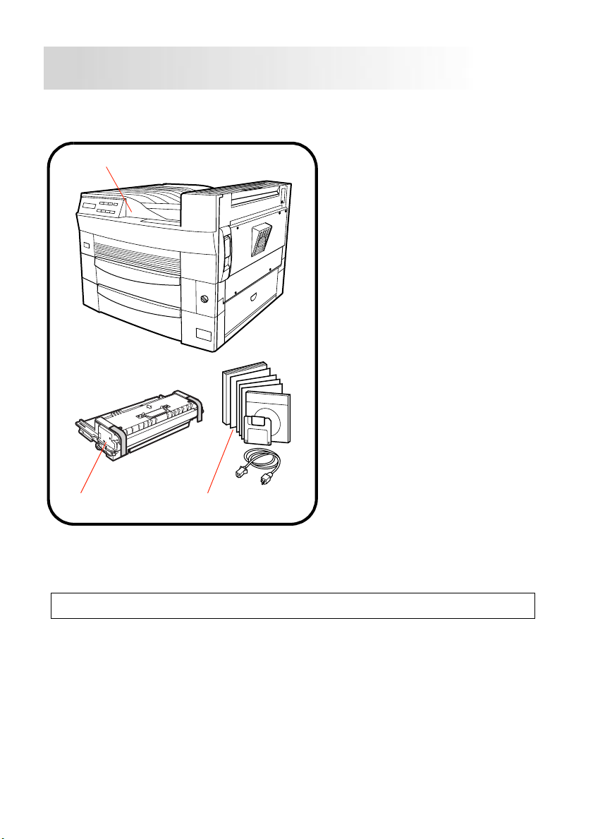
Unpacking the Printer
Step 1
Before operating your printer, read this Quick Guide carefully
from cover to cover. Use this guide for reference.
1
1.Printer
2.Acce ssories
User’s Manual
Printer Driver
User’s Manual
for Windows 3.1
Quick Guide
CD-ROM
Floppy Diskette
Power cord
Paper Size Label
Warranty card
Registration card
3.Imaging Cartridge
3
1.
Take the items and accessories shown above out of the carton.
2
Note
After unpacking, keep all packing materials out of the reach of children.
2.
Remove the plastic bag and peel off the shipping tape from the printer.
1
Page 5
3.
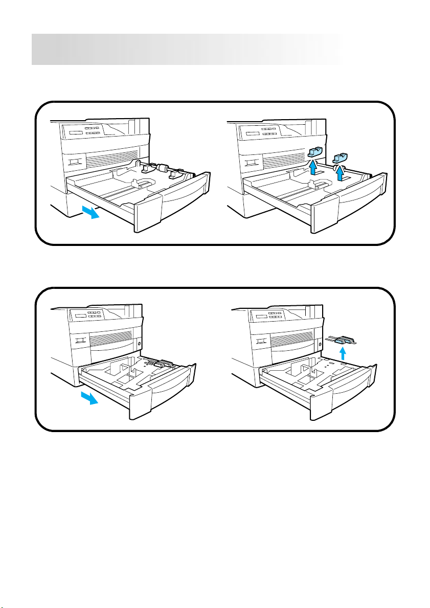
Pull out Tray 1 and remove the cushion from Tray 1.
Close Tray 1.
4.
Pull out Tray 2 and remove the cushion from Tray 2.
Close Tray 2.
Step 1
2
Page 6

5.
Pull the side cover release lever and open the side cover.
Peel off the protective sheet from the image transfer roller.
Close the side cover.
Step 1
3
Page 7
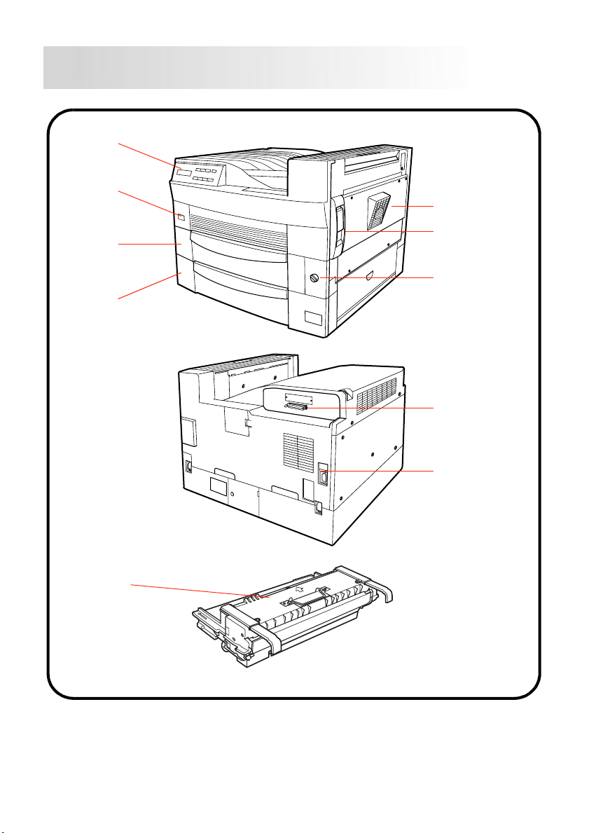
Printer Parts
Control
panel
Power
switch
Tray 1
(multipurpose
tray)
Tray 2
(500-sheet
tray)
Reference 1
Side cover
Side cover
release lever
Paper size
selection dial
Parallel interface connector
Power cord
socket
Imaging
cartridge
4
Page 8
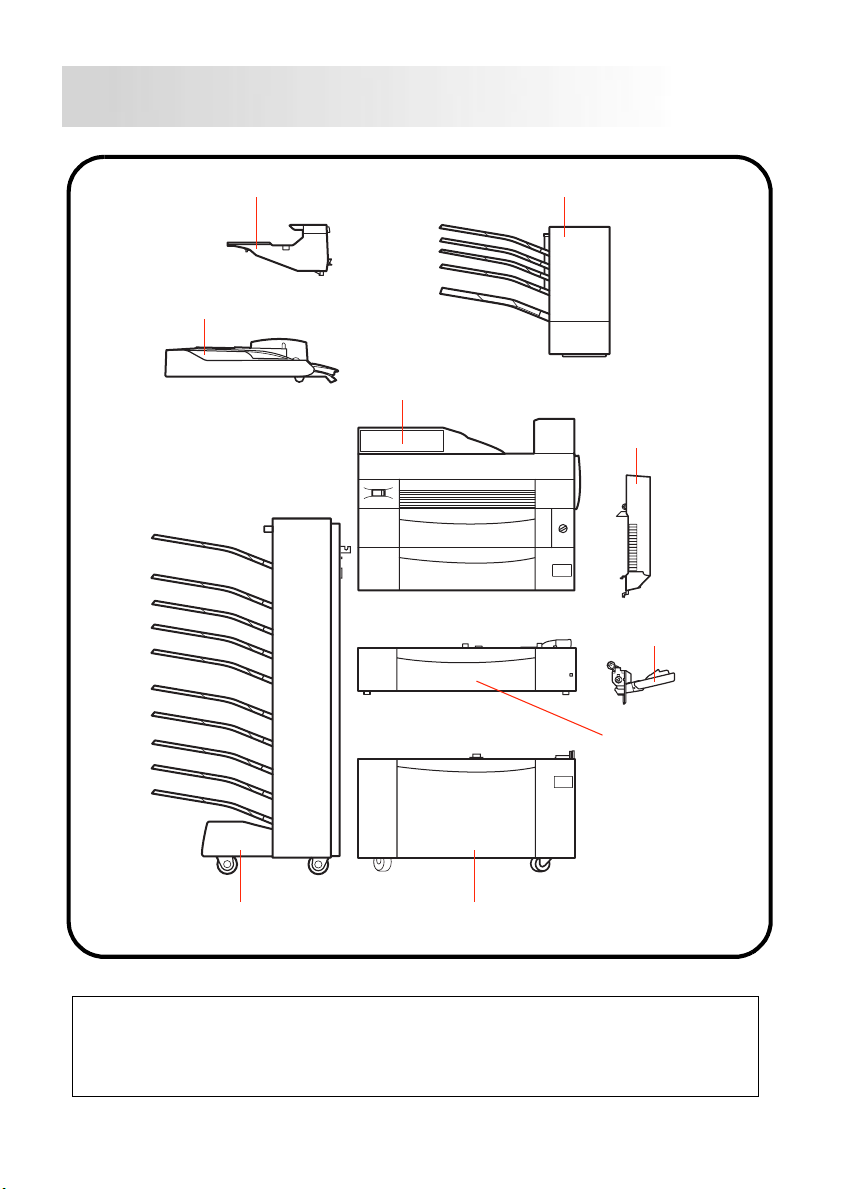
PageWorks 25 Overview
Upper attachment (option) 5-bin Mail-bin (option)
Horizontal
transport unit (option)
Printer
Reference 2
Duplex unit
(option)
Manual feed unit
(option)
Tray 3/4/5
(250-sheet paper
feed unit) (option)
(500-sheet paper
feed unit) (option)
10-bin Mail-bin
(option)
2500 sheet tray (LCC) (option)
Note
The duplex unit, manual feed tray, 500-sheet paper feed unit, 250-sheet paper feed
unit, 2500 sheet tray, 5 -bin mail-bin, 10-bi n mail-bin (includ ing the horizontal transport
unit and upper attachm ent), SIMM and NIC (Net work Interface C ard) are a ll avail able
options for your printer. For more information, please refer to the User’s Manual.
5
Page 9
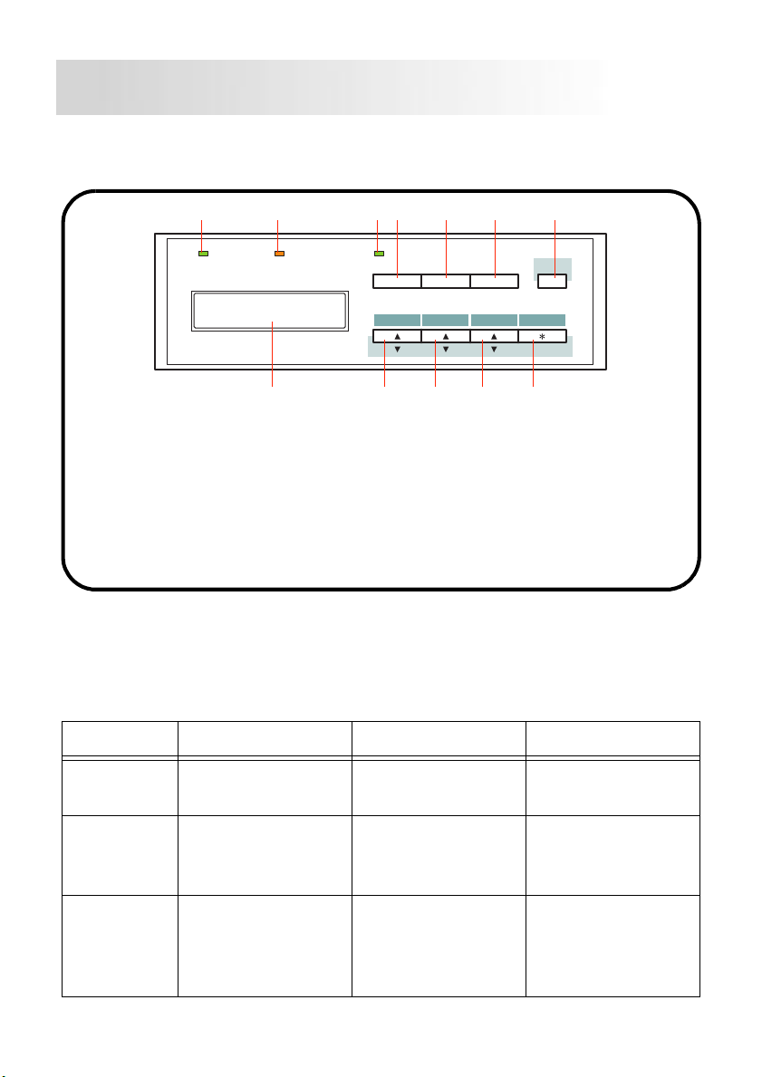
Control P anel
Reference 3
The contr ol panel consists of a displa y panel (LCD), three i ndicator li ghts
and eight function keys.
12 34567
Data Message
Data indicator
1
Message indicator
2
On Line indicator
3
On Line key
4
Proceed key
5
Tray1 Paper key
6
Proceed
On Line
Menu
7
8
9
10
11
12
Tray 1 Paper
Item Select
Shift key
Enter/Job Cancel key
Select key
Item key
Menu key
LCD
Shift
Enter
Job Cancel
89101112
Indicator Lights
There are three indicator lights that the printer uses to a lert you to the
following situations:
Indicator On Off Blinking
On Line The printer is ready
to receive data.
The printer cannot
receive data.
Going off-line.
Data Data is being stored
in the printer memory.
Message Engine error.
The printer requires
service.
No data i s s t ored in
the printer memory.
The printer is receiving and processing data.
No error. Recoverable error,
such as paper empty, paper misfeed,
etc.
6
Page 10
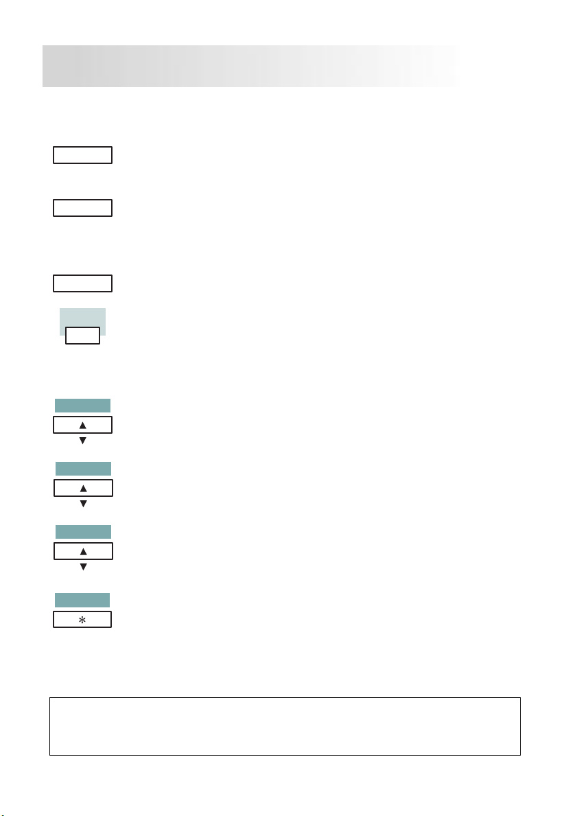
Key Functions
Reference 3
On Line
Proceed
Tray 1 Paper
Shift
Menu
Item
Select
Enter
Job Cancel
Press this key to switch between online and offline modes. The printer
must be online in order to receive data.
Press this key to resume printing after one of the following situations has
occurred:
- when a Paper Size Error occurs.
- when a Memory Overflow o r Job Too Complex error occ urs.
- when the LOAD XX message appears due to a paper size error.
Press this key in order to enter the mode for setting the paper size (when
the dial on the Tray1 is set to
only enter this mode when the printer is off-line.
The shift key perform s various fun ctions when pres sed in combin ation with
the following other keys:
Menu key
Item key
Select key
order.
Press this key to enter the Menu mode when the printer is off-line. Press
this key repeatedly to display the Menu group in order.
Press this key to enter the Item mode when the printer is in the Menu
mode. Press this key repeatedly to display the items in order.
Press this key to ent er the User Selection mod e when the printer is i n either
the Item mode or the Tray1 Paper Menu mode. Press this key repeatedly
to view the user selection values in order. Press and hold the
in order to increase the value at high speed.
Press this key to s ave User Sel ectio n settings . This ke y can be press ed in
combination with the
cessed and to clear the data for a job from th e printer’s memory. A jo b can
only be cancelled by us ing the
the
ther on or blinking.
: each menu will be displayed and rotated in reverse order.
: each item will be displayed and rotated in reverse order.
: each user selection value is displ ayed and ro tated in rev erse
key when the printer is off-line and when the Data indicator is ei-
Shift
User set
key to cancel a job that is currently being pro-
Shift
) and media type for Tray1. You ca n
Enter/Job Cancel
key in combination with
Select
key
Note
In order to cancel a job u sing the
dure described above, the printer must be off-line. You can force the printer
to go off-line by pressing the
Enter/Job Cancel
On Line
key while printing.
key through the proce-
7
Page 11
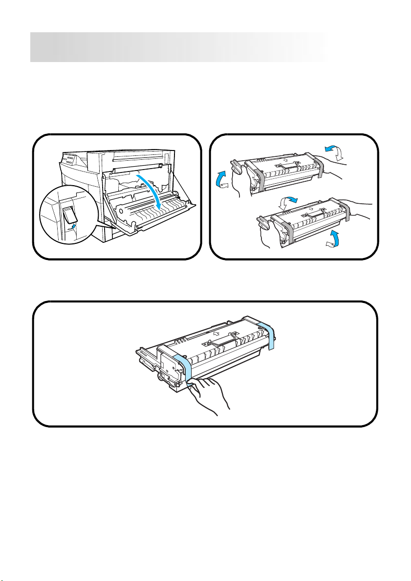
Installing the Imaging Cartridge
Step 2
1.
Pull the side cover release lever
and open the side cover.
3.
Carefully remove the packing tape that is adhered to the grips by pulling
from the bottom up.
2.
Take the imaging cartridge out of
the carton.
Holding it with both hands, shake
it left and right, forward and
back.
8
Page 12
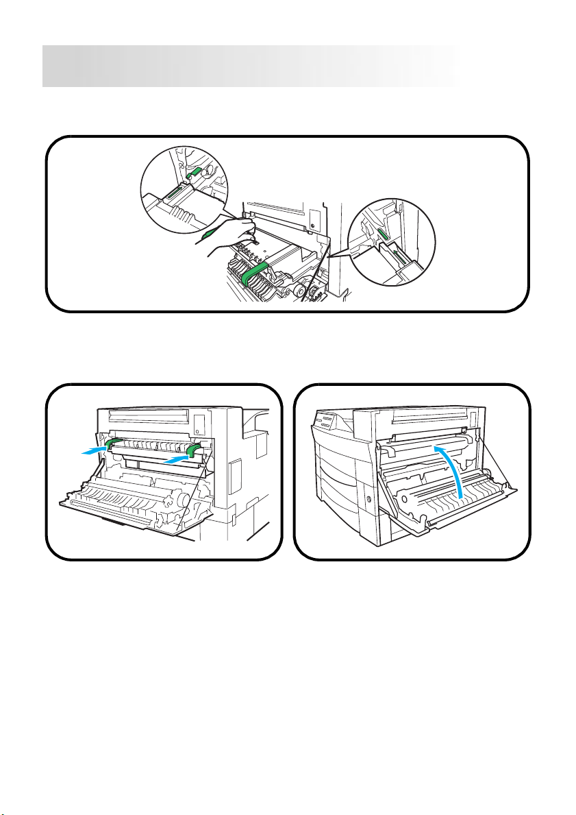
Step 2
4.
Align the green guides on the imaging cartridge with the slot bearing the
green seal located inside of the printer.
5.
Insert the imaging cartridge as
far as it will go inside of the
printer.
6.
Close the side cover.
9
Page 13
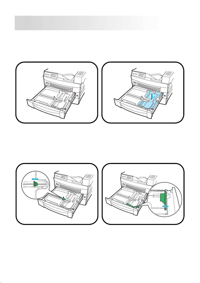
Loading Paper
Loading Paper onto Tray1
1.
Slide open Tray 1.
Step 3
2.
Press down on the paper lifting
plate locate d inside of tr a y 1 until
it clicks into place.
3.
Adjust the green clip to the
appropriate paper size by
squeezing its sides and sliding it
through the runner at the bottom
of the tray.
4.
Press the green button located
near the outer edge of the tray to
adjust the paper guides.
10
Page 14
Step 3
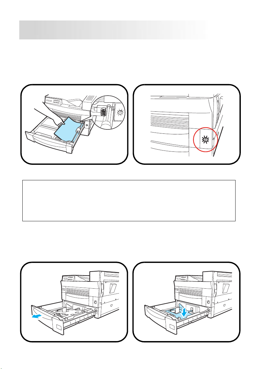
5.
Load the proper size of paper
within the guides. The stack of
paper that is loaded onto the tray
should not exceed the maximum
level indicator (see illustration).
Note
• Before setting the paper size, set the media type for Tray 1 through the
Tray 1 Paper Mode on the control panel.
• When printing on envelopes and custom sized paper, it is necessary to set
the dial to
menu through the Control Panel.
User Set
and then specify the paper size in the Tray1 paper
6.
Close Tray1 and set the size of
paper loaded in the tray on the
dial.
Loading Paper onto Tray2
1.
Slide open Tray 2.
11
2.
Press down on the paper lifting
plate locate d inside of tr a y 2 until
it clicks into place.
Page 15
Step 3
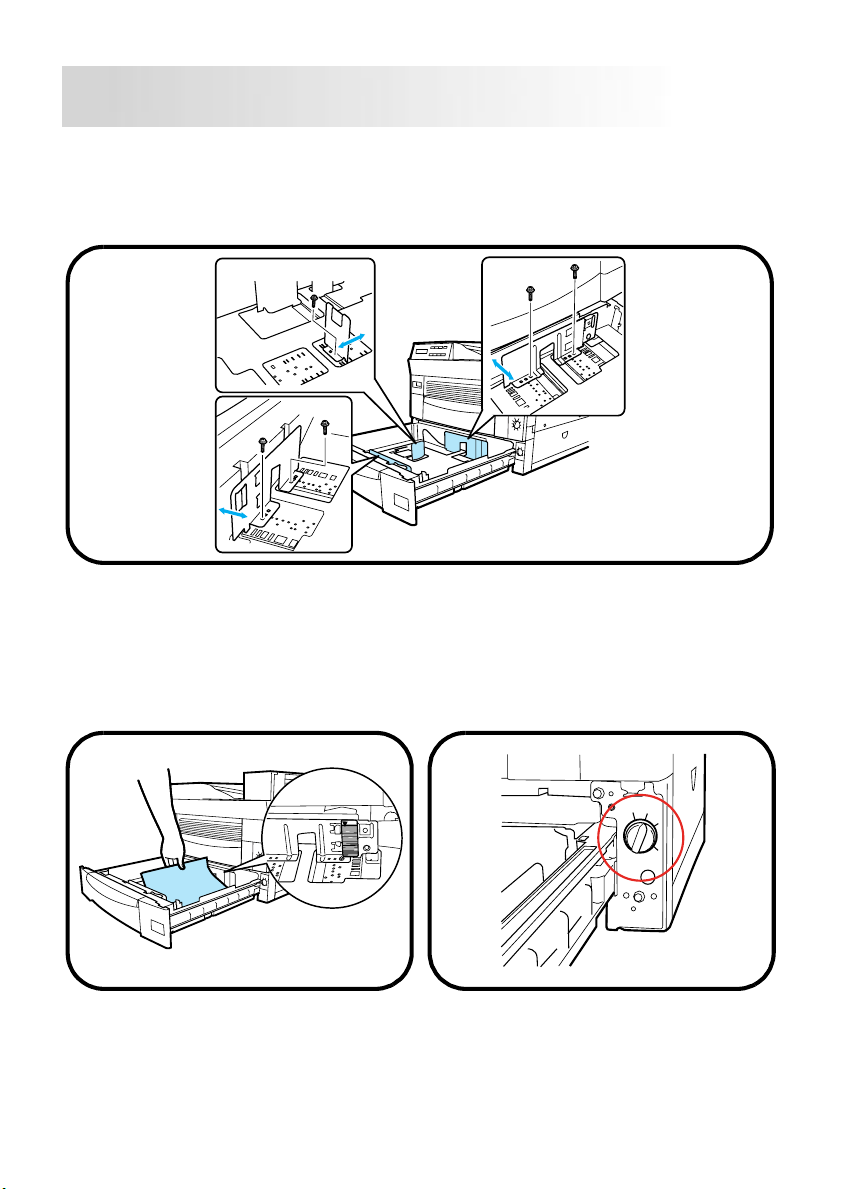
3.
If necessary, adjust the paper braces to the size of the paper to be loaded.
Use a phillip’s screwdriver to remove the braces from the tray. Be sure to
secure the braces into their new position using the screwdriver before proceeding to step 4.
4.
Load the proper size of paper
within the braces. The stack of
paper that is loaded onto the tray
should not exceed the maximum
level indicator (see illustration).
12
5.
Set the size of paper loaded in
the tray on the dial, and close
Tray 2.
Page 16
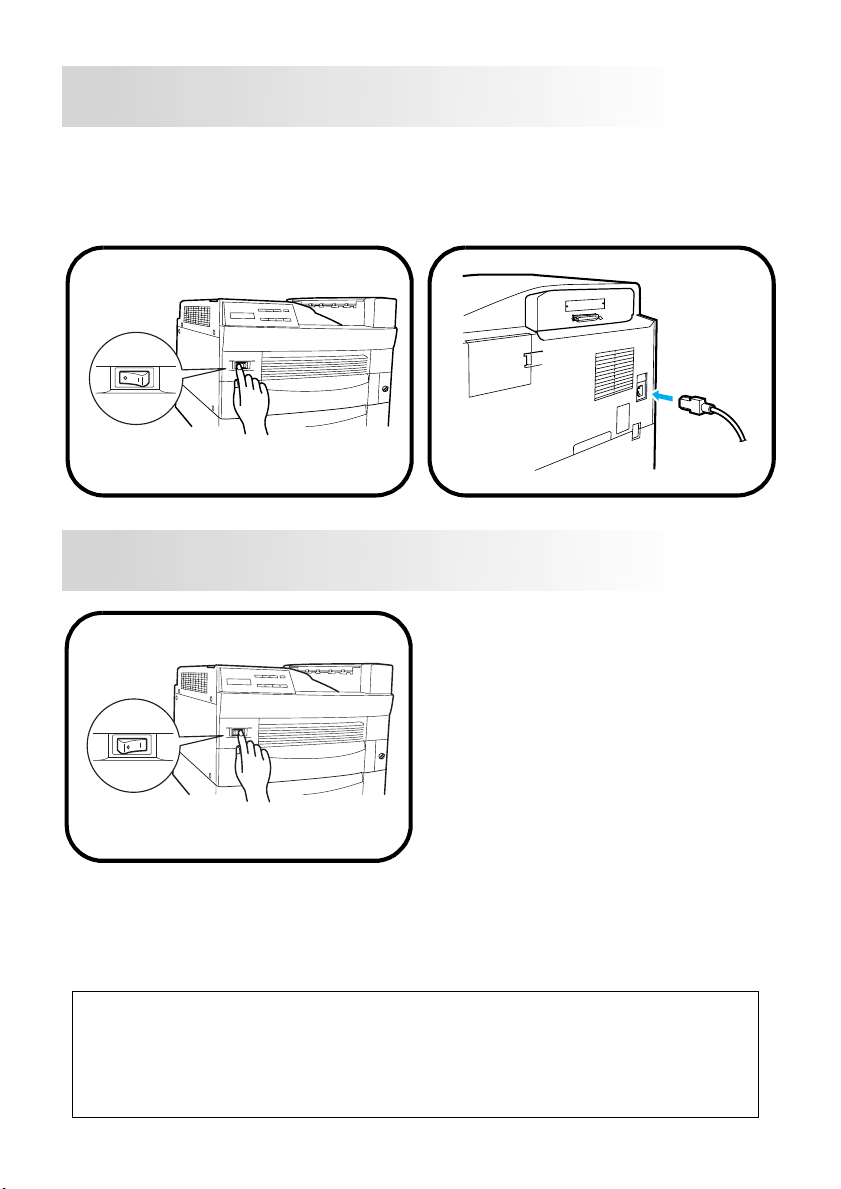
Connecting the Power Cord
Step 4
1.
Make sure that the printer’s
power switch is in the O (Off)
position.
2.
Connect one end of the power
cord that comes with the printer
to the power cord socket. Plug
the other end into a power outlet.
Turning the Power On/Off
Turning the power ON
After connecting the printer to a
power outlet, press the powe r
switch to the I (On) position.
In about 60 seconds, the READY
message is shown on the LCD
display, indicating that the printer
is ready to print.
Step 5
Turning the power OFF
Press the power switch to the O (Off) position to turn the printer off.
Note
DO NOT turn the power OFF while:
•printing
• the printer is receiving data from the computer (the indicator on the con-
trol panel is blinking)
• resetting the printer
13
Page 17
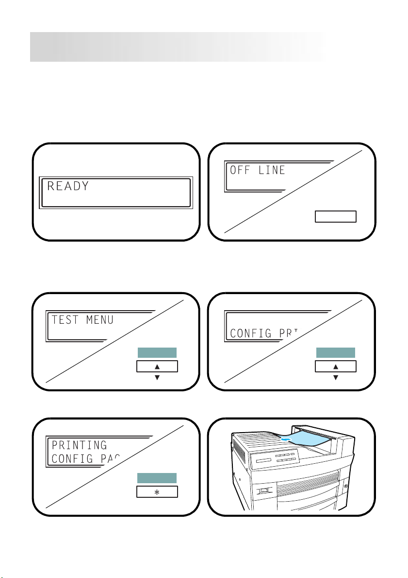
Printing a Test Page
Step 6
1.
Turn the printer on.
Make sure that Let ter- siz e p aper
is loaded into the printer’s feeding
tray.
Make sure that the
sage is shown on the LCD displa y.
3.
Press the
until the
Menu
TEST MENU
READY
key repeatedly
is found.
mes-
2.
Press the
the printer off-line.
4.
Press the
FIG PRINT
display.
On Line
Item
appears on the LCD
key to take
On Line
key once.
CON-
5.
Press the
Menu Item
Enter
key to start printing the test page.
Enter
Job Cancel
14
Page 18
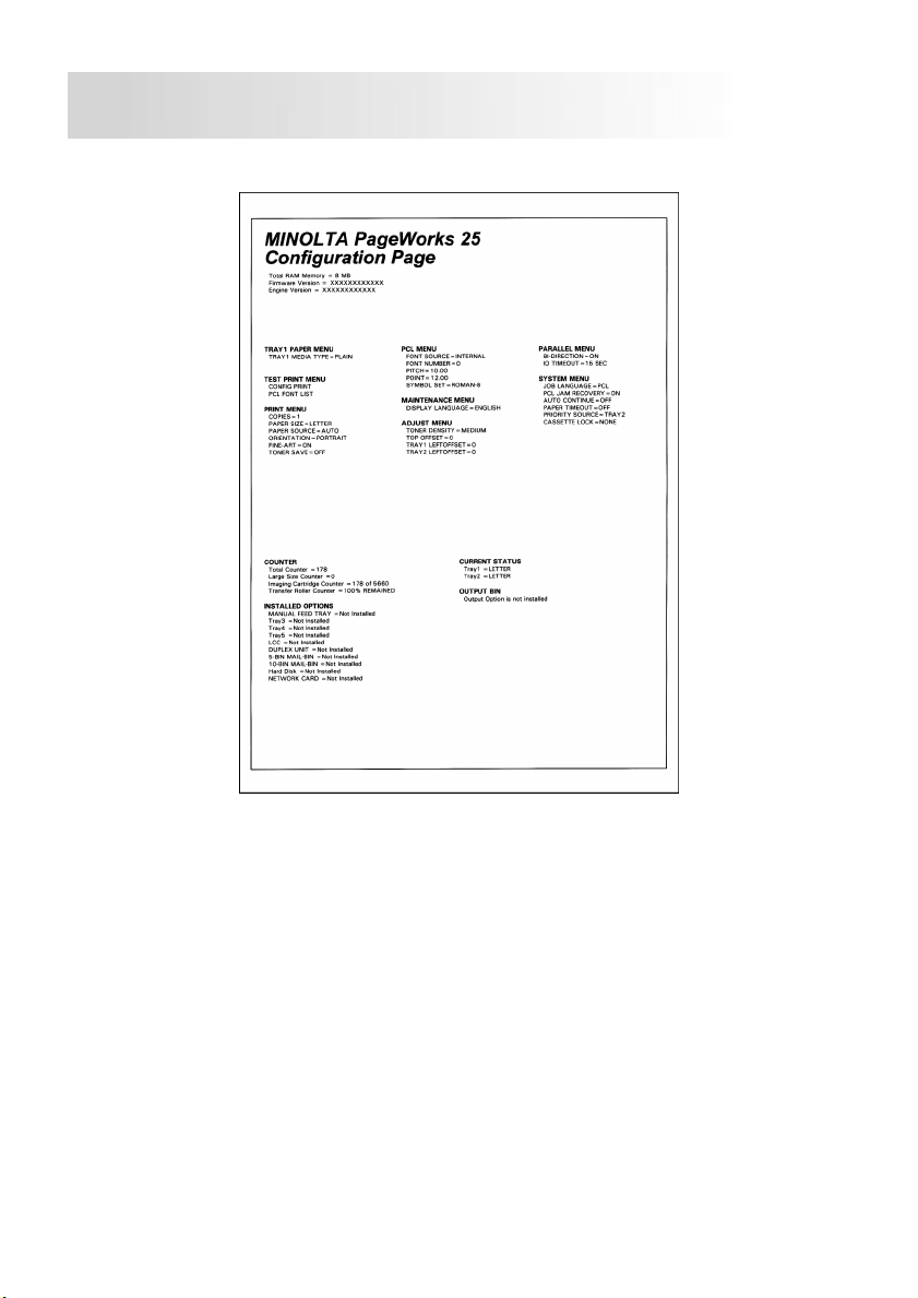
Sample
Step 6
15
Page 19
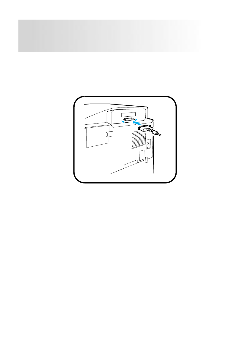
Connecting the Printer to
Step 7
the Computer (Local Connectio n)
1.
Turn the printer and the computer off.
2.
Connect one end of the interface cable to the parallel port of the computer.
3.
Connect the other end of the cable to the parallel connector on the back of
the printer. Secure the cable using the two clips on the parallel connector.
16
Page 20

Installing the Printer Driver
Step 8
Install the printer driver to control printing from your computer.
You can install the printer driver for Windows 95, Windows 98 or Windo ws
NT 4.0 from the Minolta PageWorks 25 Printer Drivers CD-ROM.
Follow the instructions described below and for more details , see the
User’s Manual that comes with your printer.
Windows 95/98
Installing from CD-ROM (Auto Run)
1. Turn on your computer and start up Windows 95/98.
2. Insert the
computer’s CD-ROM drive.
3. The opening window automatically appears on the screen.
Click
After installing the printer driver, the
icon appears in the
Note
If the auto run does not perform, double-click the
ROM. The opening window appears on the screen. Click
low the instructions that appear on your computer screen to complete the installation.
Minolta PageWorks 25 Printer Drivers
PCL Driver
and follow the instructions.
Minolta PageWorks/Pro 2 5
Printers
folder.
CD-ROM into your
Install.exe
from the CD-
PCL Driver
printer
and fol-
Plug and Play installation
Make sure that the printer is connected to your computer with the parallel
interface cable.
1. Turn on the printer.
2. Turn on your computer and start up Windows 95/98.
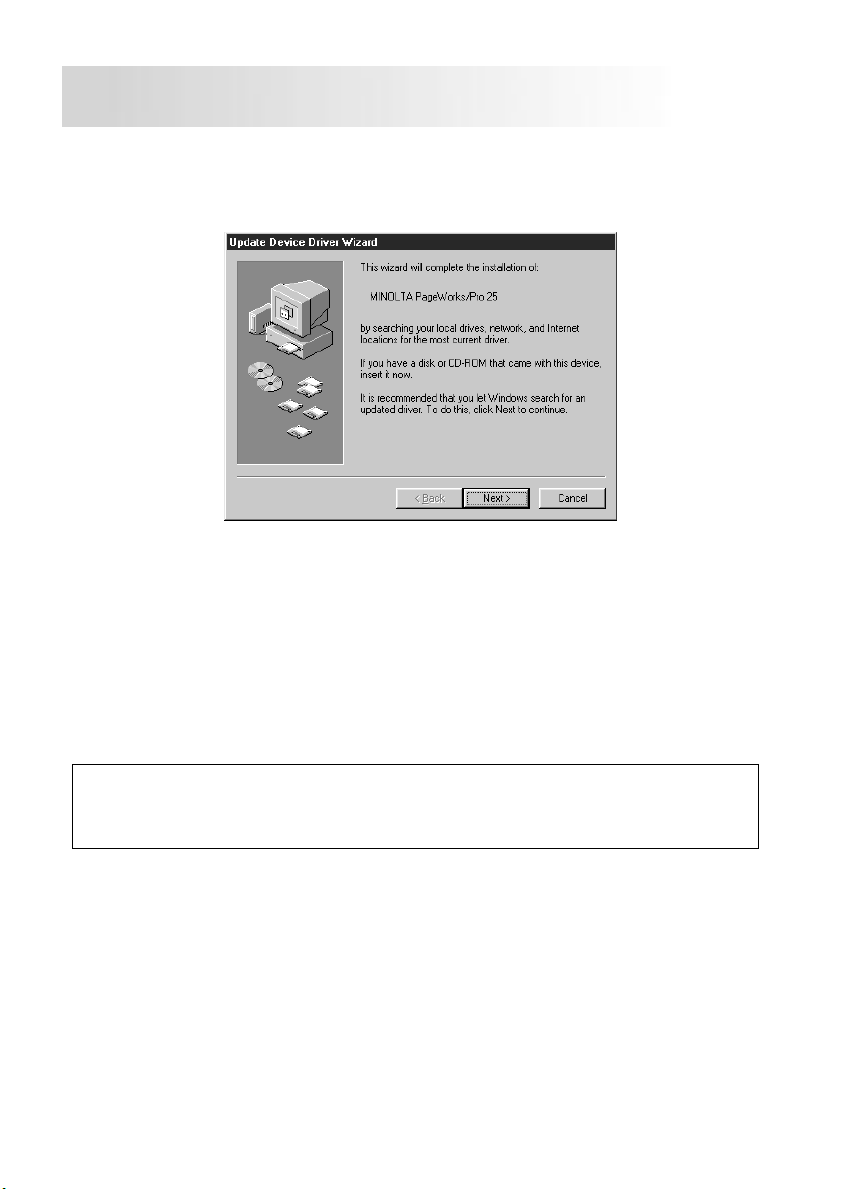
3. At the
Update Device Driver Wizard
log box, make sure your printer name is displayed and click the
ton.
(If the Update Device Driver Wizard or Add New Hardware Wizard dialog
box does not appear, see “Auto Run”.)
Add New Hardware Wizard
or
Next
17
dia-
but-
Page 21
Step 8
Follow the instructions below for installing the printer driver under Windows 95.
Follow the instructions displayed on the screen in order to install the printer
driver under Windows 98.
4. Insert the
computer’s CD-ROM drive. For this example, we will assume that the CDROM is located in drive D.
5. Click the
ton.
6. Follow the instructions displayed onscreen. After installing the printer driver,
the
Minolta PageWorks 25 Printer Drivers
Other Location
Minolta PageWorks/Pro 25
button and type
printer icon appears in the
D:\Driver
CD-ROM into your
and click the OK but-
Printers
Note
When installing the Minolta PageWorks 25 printer driver through the Update
Device Driver Wizard or Add New Hardware Wizard, the Status Display and
the uninstall.exe file will not be installed.
18
folder.
Page 22

Windows NT 4.0
Installing from CD-ROM (Auto Run)
1. Turn on your computer and start up Windows NT 4.0.
2. Insert the
computer’s CD-ROM drive. For this example, we will assume that the CDROM is located in drive D.
3. The opening window automatically appears on the screen.
Click
After installing the printer driver, the
icon appears in the
Minolta PageWorks 25 Printer Drivers
PCL Driver
and follow the instructions.
Minolta PageWorks/Pro 2 5
Printers
folder.
Step 8
CD-ROM into your
printer
For details, refer to
Chapter 4
of the
User’s Manual
.
19
Page 23
Printer Menus
Menu Operations
Reference 4
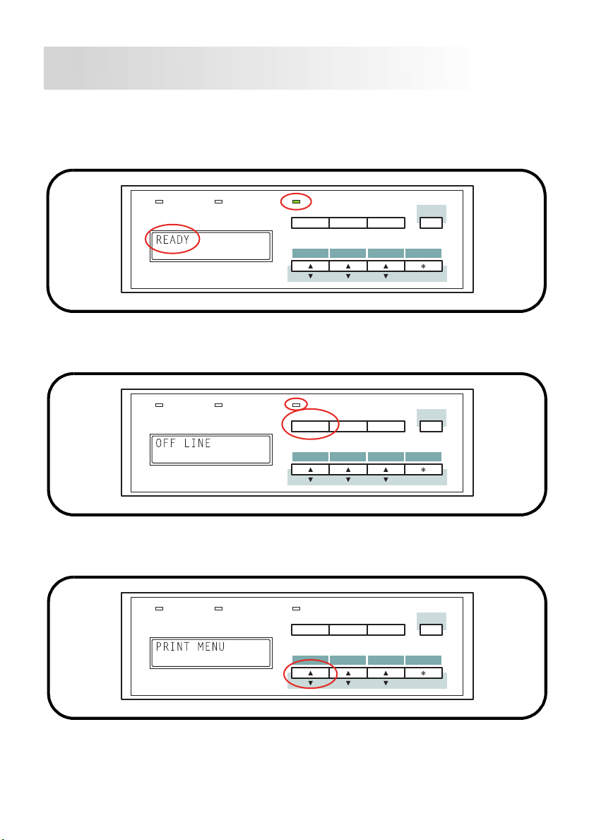
1.
Make sure that
READY
indicator is lit.
Data Message
2.
Press the
appears and
3.
Press the
On Line
key on the control panel. The
On Line
Data Message
Menu
key repeatedly until the desired menu is found.
(For example, PRINT MENU.)
is shown on the LCD display and that the
On Line
Menu
Proceed
Tray 1 Paper
Item Select
Shift
Enter
Job Cancel
OFF LINE
message
indicator goes out.
On Line
Menu
Proceed
Tray 1 Paper
Item Select
Shift
Enter
Job Cancel
On Line
Data Message
20
On Line
Menu
Proceed
Tray 1 Paper
Item Select
Shift
Enter
Job Cancel
Page 24
Reference 4
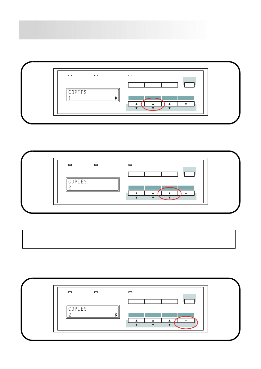
4.
Press the
Item
key repeatedly until the desired item is found.
(For example, COPIES.)
Data Message
5.
Press the
Select
key repeatedly to select the desired setting.
(For example, 2.)
Data Message
Note
Pressing t he
and the ready status resumes.
On Line
key during the setting operations cancels any mode
On Line
Menu
On Line
Menu
Proceed
Tray 1 Paper
Item Select
Proceed
Tray 1 Paper
Item Select
Shift
Enter
Job Cancel
Shift
Enter
Job Cancel
6.
Press the
Then, press the
Enter
key to store the changed settings.
On Line
key to complete the setting procedure of the
MENU utilities and take the printer to the ready status.
Data Message
On Line
Menu
Proceed
Item Select
21
Tray 1 Paper
Shift
Enter
Job Cancel
Page 25
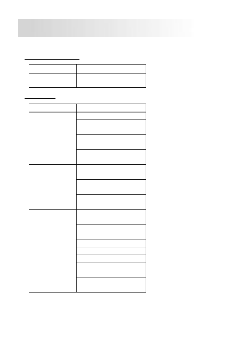
List of Menu Utilities
TRAY1 P APER key
MENU ITEM
TRAY1 PAPER
MENU
MENU key
MENU ITEM
PRINT MENU
PCL MENU
SYSTEM MENU
TRAY1 MEDIA TYPE
TRAY1 PAPER SIZE
COPIES
PAPER SIZE
PAPER SOURCE
ORIENTATION
DUPLEX
FINE-ART
TONER SAVE
FONT SOURCE
FONT NUMBER
PITCH
POINT
SYMBOL SET
LINES PER PAGE
JOB LANGUAGE
PCL JAM RECOVERY
PS JAM RECOVERY
POWER SAVE
AUTO CONTINUE
PAPER TIMEOUT
PRIORITY SOURCE
CASSETTE LOCK
CONTEXT SAVE
PS ERROR PRINT
MAIL BOX SET
Reference 4
*1: This menu is displayed only
when the dial located on
*1
the front side of Tray 1 is set
to User Set.
• Italicized items indicate
optional units and accessories that will be dis played
only when in stalled.
22
Page 26
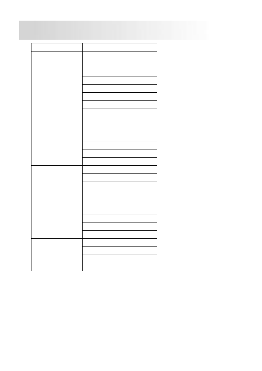
MENU ITEM
PARALLEL MENU
NETWORK
MENU
MAINTENANCE
MENU
ADJUST MENU
TEST PRINT
MENU
BI-DIRECTION
IO TIMEOUT
TCP/IP
IP ADDRESS
SUBNET MASK
DEFAULT GATEWAY
NETWARE
NETWARE FRAME
APPLE TALK
IO TIMEOUT
DISPLAY LANGUAGE
FACTORY DEFAULT
HARD DRIVE
TRANSFER LIFE
TONER DENSITY
TOP OFFSET
TRAY1 LEFTOFFSET
TRAY2 LEFTOFFSET
TRAY3 LEFTOFFSET
TRAY4 LEFTOFFSET
TRAY5 LEFTOFFSET
LCC LEFTOFFSET
DUPLEX OFFSET
CONFIG PRINT
PCL FONT LIST
PS FONT LIST
NETWORK CONFIG
Reference 4
23
Page 27
Troubleshooting
Reference 5
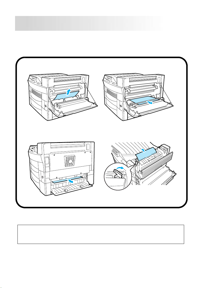
Clearing a Paper Misfeed
Remove the misfed sheet of paper by pulling it in the direction indicated by the arrow.
Inside the printer
Paper output mi sfeedPaper input misfeed (from Tray 2)
Caution
• The fusing unit inside the printer can become very hot during operation.
Do not touch the area to avoid injury.
• Be careful to avoid touching the image transfer roller.
24
Page 28

Reference 5
Solving Print Quality Problems
• Remove the imaging cartridge and gently shake it left and right a few
times to distribute remaining toner.
• Remove the imaging cartridge and check it for damage. Re place the
imaging cartridge with a new one if necessary.
• Clean the inside of the printer. (Refer to the User’s Manual.)
• Change the toner save setting of the printer driv er and try to print
again.
For more details, refer to the “Troubleshooting” and “Maintenance” section of the User’s
Manual.
No output
• Make sure that the printer is plugged in.
• Make sure that power is turned on.
• Make sure that you are using the correct type of printer cable.
• Make sure that your computer’s communication port settings are cor-
rect.
For more details, refer to the User’s Manual.
25
Page 29

MEMO
Page 30

MEMO
Page 31

Page 32

 Loading...