

Page 1
PageWorks 18
User’s Manual
Page 2
As an ENERGY STAR Partner, we have determined
E
that this machine meets the
for energy efficiency.
NERGY STAR Guidelines
What is an ENERGY STAR Printer ?
E
NERGY STAR printers have a feature that allows them to automatically “go to sleep” after a
period of inactivity. This auto-feature can reduce a machine’s annual electricity cost by 60 percent.
Page 3

Foreword
Safety Information
Laser Safety
This is a page printer which operates by means of a laser. There is no
possibility of danger from the laser, provided the printer is operated
according to the instructions in this manual.
Since radiation emitted by the laser is completely confined within protective housing, the laser beam cannot escape from the machine during
any phase of user operation.
Internal Laser Radiation
Maximum Radiation Power : 1.03 (mW) at laser aperture of the print
head unit
Wavelength : 770-810 (nm)
This product employs Class IIIb Laser Diode.
Laser Diode and Scanning Polygon Mirror are incorporated in the print
head unit.
The print head unit is NOT A FIELD SERVICE ITEM.
Therefore, the print head unit should not be opened under any circumstance.
Laser Safety
This printer is certified as a Class 1 Laser product under the
Department of Health and Human Services (DHHS)
formance Standard according to the Radiation Control for Health and
Safety Act of 1968. This means that the printer does not produce hazardous laser radiation.
U.S.
Radiation Per-
CDRH Regulations
Center for Devices and Radiological Health (CDRH)
The
Food and Drug Administration implemented regulations for laser products on August 2, 1976. Compliance is mandatory for products marketed in the United States. The label shown on the following page
indicates compliance with the CDRH regulations and must be attached
to laser products marketed in the United States.
of the U.S.
i
Page 4
Foreword
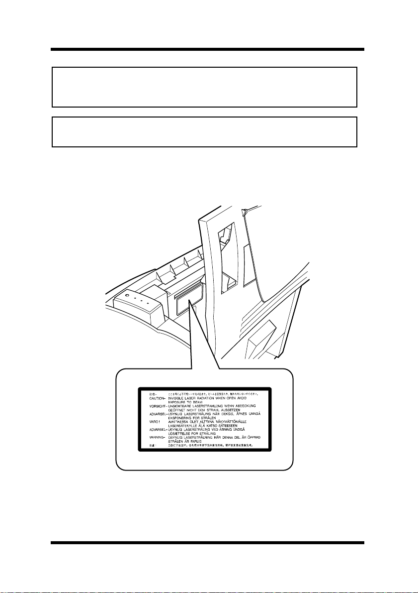
WARNING:
other than those specified in this manual may result in hazardous radiation exposure.
This is a semiconductor laser. The maximum power of the laser diode is
5mW and the wavelength is 770-810 nm.
Use of controls, adjustments or performance of procedures
WARNING LABEL
ii
Page 5

Foreword
USER INSTRUCTIONS (For U.S.A. Users)
FCC PART 15 - RADIO FREQ UENCY DEVICES W ARNING
FCC: Declaration of Conformity
Product Type Laser Beam Printer
Product Name PageWorks 18
Options
Accessories
This device complies with Part 15 of the FCC Rules.
Operation is subject to the following conditions;
(1) this device may not cause harmful interference, and
(2) this device must accept any interference received, including interference that
may cause undesired operation.
Minolta Corporation
101 Williams Drive, Ramsey, New Jersey 07446
Telephone number: 201-825-4000
This equipment has been tested and found to comply with the limits for
a Class B digital device, pursuant to Part 15 of the FCC Rules. These
limits are designed to provide reasonable protection against harmful
interference in a residential installation. This equipment generates,
uses and can radiate radio frequency energy and, if not installed and
used in accordance with the instructions, may cause harmful interference to radio communications. However, there is no guarantee that
interference will not occur in a particular installation. If this equipment
does cause harmful interference to radio or television reception, which
can be determined by turning the equipment off and on, the user is
encouraged to try to correct the interface by one or more of the following measures:
Second Paper Cassette Unit (4166)
Third Paper Cassette Unit (4166)
Duplex Unit (4168)
DRAM SIMM (Maximum 64MB)
Adobe PostScript SIMM (4179-291)
Network Interface Card (4179-241, 4179-251)
● Reorient or relocate the receiving antenna.
● Increase the separation between the equipment and the receiver.
● Connect the equipment into an outlet on a circuit different from
that to which the receiver is connected.
● Consult the dealer or an experienced radio/TV technician for help.
iii
Page 6

Foreword
This device must be used with a shielded interface cable and shielded
network (10/100BaseT and/or 10Base2) cable. The use of non-shield
cables is likely to result in interference with radio communications and
is prohibited under FCC rules.
The design and production of this unit conform to FCC regulations,
and any changes or modifications must be registered with the FCC and
are subject to FCC control. Any changes made by the purchaser or user
without first contacting the manufacturer will be subject to penalty
under FCC regulations.
USER INSTRUCTIONS (For Canada Users)
INTERFERENCE-CAUSING EQUIPMENT STANDARD
(ICES-003 ISSUE 3) WARNING
This Class B digital apparatus complies with Canadian ICES-003.
Cet appareil numérique de la classe B est conforme à la norme NMB003 du Canada.
iv
Page 7
Foreword
OZONE RELEASE (For All Users)
During printer operation, a small quantity of ozone is released. This
amount is not large enough to harm anyone adversely. However, be
sure the room where the machine is being used has adequate ventilation, especially if you are printing a high volume of materials, or if the
machine is being used continuously over a long period.
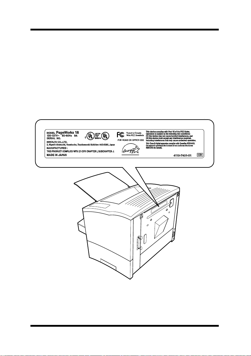
WARNING LABEL
v
Page 8

Foreword
Welcome
And thank you for selecting a Minolta PageWorks 18 Printer!
This
User’s Manual
operates. It also provides you with troubleshooting tips as well as general precautions you should observe when operating the printer. To
ensure the top performance and effective use of your printer, read this
manual carefully from cover to cover, and keep it at hand for later reference.
No part of this document may be reproduced, transmitted, transcribed,
stored in a retrieval system, or translated into other languages without
the express written prior consent of Minolta Co., Ltd.
The contents of this manual are subject to change without notice.
Trademark Acknowledgments
PCL is a registered trademark of Hewlett-Packard Company.
Centronics is a registered trademark of Centronics Inc.
MS-DOS, Microsoft, Windows, and Windows NT are registered trademarks of Microsoft Corporation.
IBM is a registered trademark of International Business Machines Corporation.
Adobe and PostScript are registered trademarks of Adobe Systems, Inc.
PageWorks is a trademark of Minolta in the U.S. and Canada.
Fine-ART and Fine Micro Toning are trademarks of Minolta Co., Ltd.
All other brand or product names are trademarks or registered trademarks of their respective companies or organizations.
explains the functions of the printer and how it
vi
Page 9

Foreword
Technical Support
Technical support for all Minolta PageWorks printer products is available 24 hours a day, seven days a week by calling
(from within North America). Minolta also maintains a W eb site which
provides printer driver downloads, Frequently Asked Questions and
handles all e-mail requests for technical assistance at:
http://www.minoltaprinters.com
Please be prepared to provide the following information when contacting Minolta Technical Support:
• Model Name
• Serial number
• A detailed description of the problem
For questions or problems with installation, please be prepared to provide the following additional information:
• Brand name and model number of the computer
• Type of processor
• Type of operating system
.
1-800-459-3250
• Amount of installed RAM
vii
Page 10

Contents
CONTENTS
Chapter 1: Introduction
Features..................................................................1-1
Printer Parts and Accessories .............................1-2
Control Panel.........................................................1-4
Indicator Lights...................................................1-4
Control Panel Button..........................................1-8
Job Cancel....................................................1-8
Print Configuration........................................1-8
Form Feed....................................................1-8
Chapter 2: Setting-up
Installation Precautions........................................2-1
Selecting a Location for the Printer....................2-1
Power Source.....................................................2-2
Grounding ..........................................................2-2
Space Requirements.......................................... 2-3
Operational Precautions.......................................2-4
Operating Environment......................................2-4
Printer ................................................................2-4
Printer Supplies..................................................2-6
viii
Page 11

Contents
Setting-up...............................................................2-7
Installing the Face-Down Tray............................2-7
Installing Tray 1..................................................2-8
Connecting the Power Cord...............................2-9
Loading Paper..................................................2-10
Turning On the Printer......................................2-12
Testing the Printer............................................2-13
Connecting to a Computer...............................2-15
Options.................................................................2-16
SIMM (Single In-line Memory Module)............. 2-16
Installing the Optional SIMM.......................2-16
Duplex Unit.......................................................2-21
Installing the Duplex Unit............................2-21
Second/Third Paper Cassette Unit...................2-24
Installing the Optional Second/Third
Paper Cassette Unit....................................2-24
Adobe PostScript ROM-SIMM..........................2-28
Installing the Optional Adobe PostScript
ROM-SIMM.................................................2-28
Network Interface Card (NIC)...........................2-33
Installing the Optional
Network Interface Card...............................2-33
ix
Page 12

Contents
Chapter 3: Using the Printer
Paper.......................................................................3-1
Type....................................................................3-1
Size....................................................................3-1
Standard size................................................3-1
Envelopes and custom sizes
(Tray 1 and Manual Feed Tray) .....................3-2
Loading Paper........................................................3-3
Loading Paper onto Tray 1.................................3-4
Loading Paper onto Tray 2/Tray 3.......................3-7
Manual Paper Feed..........................................3-11
Printing on Envelopes......................................3-13
Duplex Printing.................................................3-15
Paper Type..................................................3-16
Paper Size ..................................................3-16
Chapter 4: Printer Driver
Introduction............................................................4-1
System Requirements...........................................4-1
Installing the Printer Driver Under
Windows 95/98.......................................................4-2
To Install the Printer Driver Using
the Installer (Auto Run)......................................4-2
To Uninstall the Printer Driver ............................4-6
x
Page 13

Contents
Installing the Printer Driver Under
Windows NT 4.0.....................................................4-8
To Install the Printer Driver Using
the Installer (Auto Run)......................................4-8
To Uninstall the Printer Driver ..........................4-14
Installing the Printer Driver Under
Windows 3.1.........................................................4-16
To Install the Printer Driver...............................4-16
To Uninstall the Printer Driver ..........................4-19
Displaying the Driver Setup Dialog
(Windows 95/98/NT 4.0).......................................4-21
To Display the Driver Setup Dialog
Under Windows 95/98......................................4-21
To Display the Driver Setup Dialog
Under Windows NT 4.0....................................4-23
Using the Printer Driver Under
Windows 95/98/NT 4.0.........................................4-25
Common Buttons .............................................4-25
Paper................................................................4-26
Page Layout .....................................................4-31
Quality..............................................................4-36
Device Option...................................................4-40
About................................................................4-40
Displaying the Driver Setup Dialog
(Windows 3.1) ......................................................4-41
xi
Page 14

Contents
Using the Printer Driver Under Windows 3.1....4-43
Common Buttons .............................................4-43
Settings............................................................4-44
DOS Printing Utilities..........................................4-49
Installing the Printer Driver Under DOS............4-49
Loading and Unloading the Status Display ......4-51
To Load the Status Display From the
DOS Prompt.....................................................4-51
To Remove the Status Display From Memory..4-51
Accessing the Printer Control Panel.................4-52
To Access the Printer Control Panel ................4-52
To Exit the Printer Control Panel......................4-52
Using the Printer Control Panel.........................4-53
Getting Around in the Printer Control Panel.....4-53
To Print a Test Page or Demo Page.................4-54
To Register Installed Options...........................4-54
Printer Control Panel Screens............................4-54
Common Buttons .............................................4-54
Paper Screen...................................................4-55
Font Selection Screen......................................4-57
Output Quality Screen......................................4-58
Counter Screen................................................4-59
Configuration Screen .......................................4-60
Printer Setting Screen......................................4-61
xii
Page 15

Contents
Using the Status Display ....................................4-63
To Display the Status Display...........................4-63
Status Display Screen......................................4-64
Set Display Mode Command
(Setup Menu)..............................................4-64
Change Hot Key Command
(Setup Menu)..............................................4-64
Change Popup Message Command
(Setup Menu)..............................................4-64
Close (button).............................................4-65
Help (button)...............................................4-65
Chapter 5: Printer Status Display and Control Panel
Using the Printer Status Display..........................5-1
Opening the Printer Status Display....................5-1
To Open the Printer Status Display...............5-1
To Close the Printer Status Display..............5-2
Using the Printer Status Display ........................5-2
Printer Status................................................5-2
How to recov er..............................................5-2
Printer Status figure......................................5-2
Switching Between the Expanded
and Reduced Views...........................................5-3
On-line Help.......................................................5-3
xiii
Page 16

Contents
Using the Control Panel........................................5-4
Common Buttons ...............................................5-5
Paper..................................................................5-6
Printer Setting ....................................................5-8
Test Print..........................................................5-10
Counter ............................................................5-11
Configuration....................................................5-12
Chapter 6: Maintenance
Replacing the Imaging Cartridge.........................6-1
To Replace the Imaging Cartridge .....................6-2
Cleaning the Printer ..............................................6-6
Cleaning the Outside of the Printer....................6-6
Cleaning the Paper Transport Roller..................6-7
Chapter 7: Troubleshooting
Technical Support ..............................................7-1
Clearing a Paper Misfeed......................................7-2
Inside the Printer ..........................................7-2
Paper Output Misfeed...................................7-6
Paper Input Misfeed (from Tray 1).................7-7
Paper Input Misfeed
(from Manual Feed Tray)...............................7-7
Paper Input Misfeed
(from Second/Third Paper Cassette Unit).....7-8
xiv
Page 17

Contents
Paper Misfeed in the Duplex Unit.......................7-9
Upper Misfeed ..............................................7-9
Lower Misf eed...............................................7-9
Print Quality Problems........................................7-10
Blank pages .....................................................7-10
Black pages......................................................7-10
Printout too light...............................................7-11
Printout too dark...............................................7-11
Blurred background..........................................7-12
Uneven print density ........................................7-12
Irregularities .....................................................7-12
White or black line............................................7-13
Toner smudges.................................................7-13
No output..........................................................7-14
Are you using the correct type
of printer cable?..........................................7-14
Are your computer’s communications
port settings correct?..................................7-14
Chapter 8: Specifications
PageWorks 18 Printer............................................8-1
Second Paper Cassette Unit (Option)..................8-4
Third Paper Cassette Unit (Option)......................8-5
Duplex Unit (Option)..............................................8-6
xv
Page 18

Contents
Interface Connector and Cable ............................8-7
SIMM (Option)........................................................8-8
Appendix A: Glossary
Appendix B: Index
xvi
Page 19

Chapter
Chapter 1
Introduction
Introduction
1
Page 20

Chapter 1
Introduction
Page 21

Features
Features
The Minolta PageWorks 18 is a laser beam printer developed
exclusively for use with Windows 95, Windows 98, Windows NT 4.0,
Windows 3.1 and DOS operating systems.
The various features listed below make the Minolta PageWorks 18 the
perfect printer for any size office.
• Fast 18-page per minute printing speed
Chapter 1
• PCL 6 support for faster, more precise printing
• Supports two optional Ethernet network interface cards
(10/100BaseT and 10Base2)
• Powerful 66 MHz Power PC and QuickPrint dual processors
• 4 MB of memory
• Expanded digital-documentation support through an optional
Adobe PostScript 3 SIMM
Introduction
1-1
Page 22
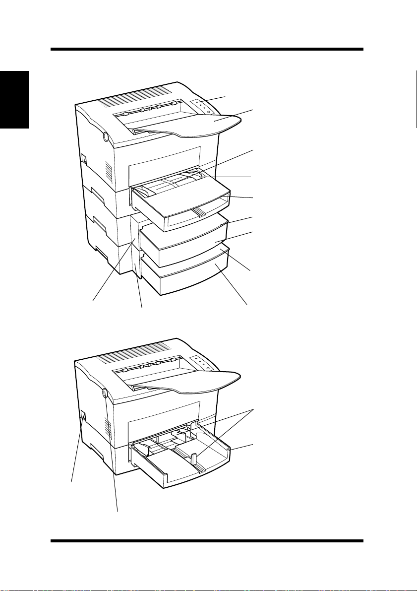
Printer Parts and Accessories
Printer Parts and Accessories
Chapter 1
Introduction
Control panel
Face-down tray
Manual feed tray
Paper size guide
Tray cover
Cassette cover (option)
Tray 2 (500-sheet
second cassette)
(option)
Cassette cover
(option)
Second paper
cassette unit
(option)
Power
switch
Top cover release button
1-2
Third paper
cassette unit (option)
Tray 3 (500-sheet
third cassette)
(option)
Paper size guide
Tray 1
(multipurpose tray)
Page 23
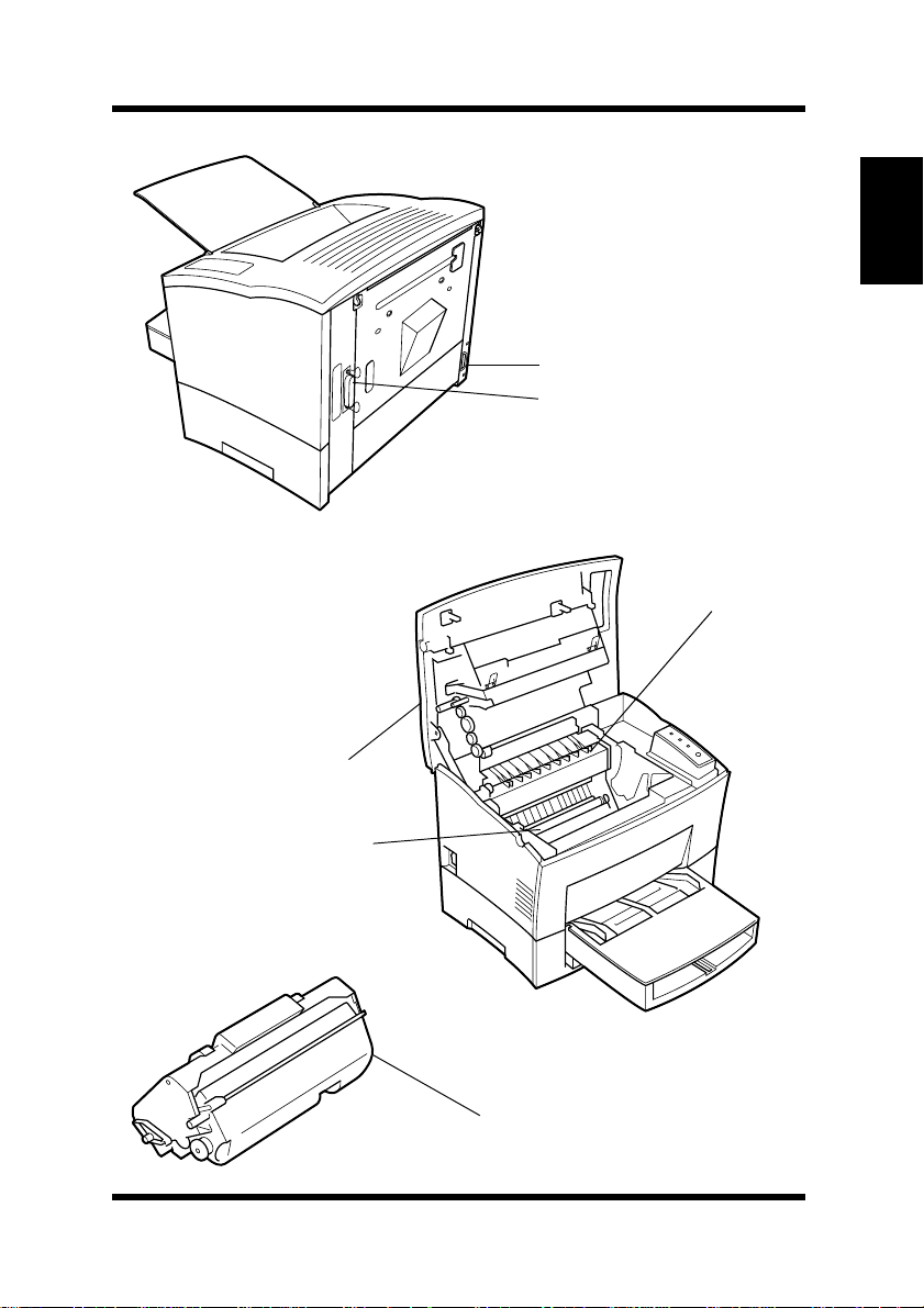
Printer Parts and Accessories
Power cord socket
Parallel interface
connector
Fusing unit
Chapter 1
Introduction
Top cover
Image transfer roller
Imaging cartridge
1-3
Page 24
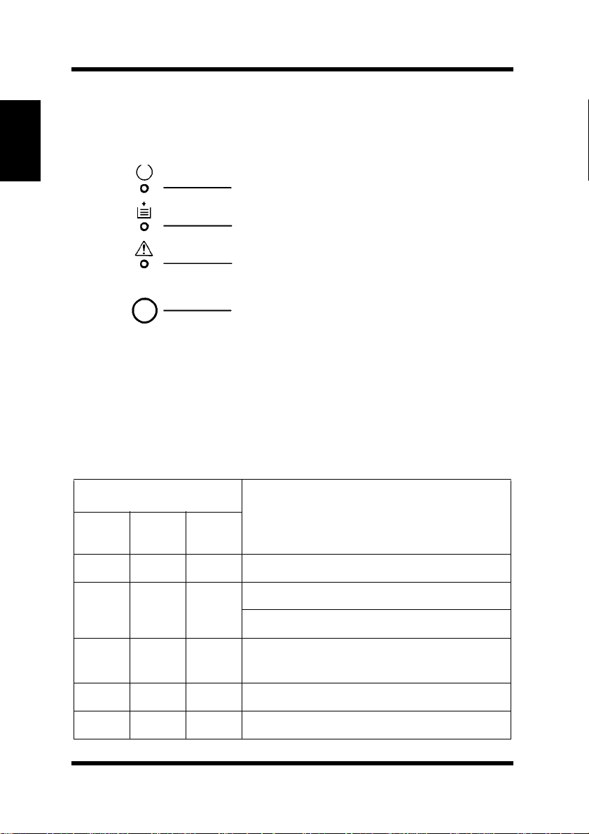
Control Panel
Control Panel
The control panel has three indicator lights and one button.
Chapter 1
Ready (green)
Paper (amber)
Introduction
Indicator Lights
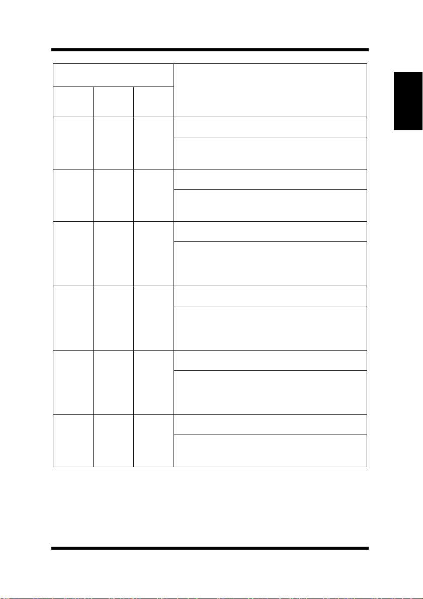
The three indicator lights turn on, off, or blink in combination to let
you know the current status of the printer. You can find out details of
the printer’s status by checking the information that appears on your
computer screen through the Status Monitor.
Ready
(green)
Blinking
Error (red)
Panel button
Indicator Lights
Paper
(amber)
On Off Off Printer is ready.
Off Off Off
Off Off
Error
(red)
Printer Status and Recommended Action
Power is off.
Turn on the printer.
Receiving data via parallel interface;
printing in progress.
Blinking
Blinking Blinking Blinking
Off On Receiving data via network interface.
1-4
Canceling job.
Page 25
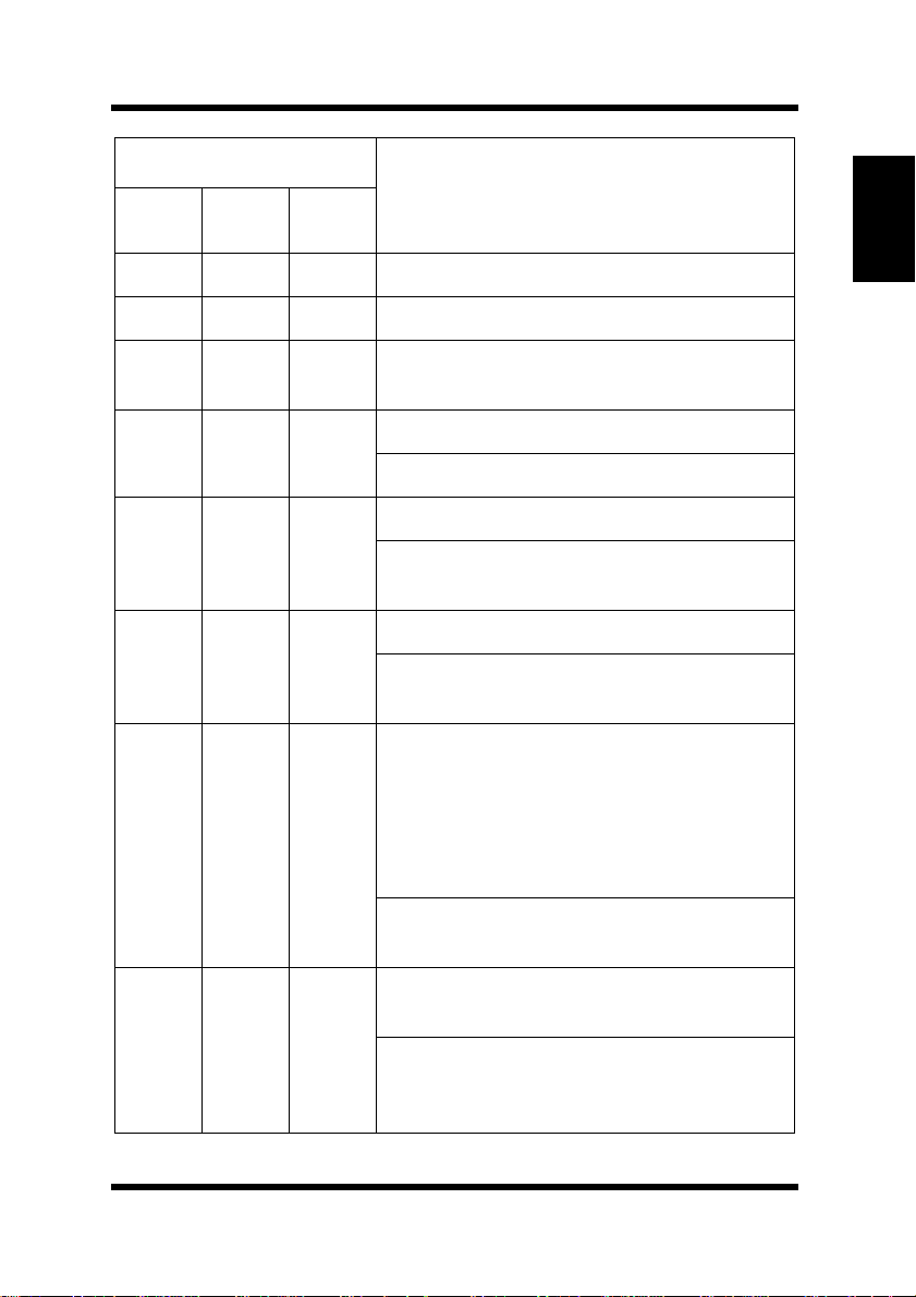
Indicator Lights
Ready
(green)
Paper
(amber)
Blinking Blinking
Error
(red)
Off Warming up.
Printer Status and Recommended Action
On On On “Power on” initial setting.
Control Panel
Chapter 1
Slow
Blinking
Off Off Power save mode.
Off On Off
On Off On
On
Off
Blinking
Blinking
Off Off
On
On
Blinking
Out of paper.
Load more paper to continue printing.
The imaging cartridge is low on toner.
Ready a new imaging cartridge. See
page 6-1.
The imaging cartridge is out of toner.
Replace the imaging cartridge. See
page 6-1.
Data is currently being compressed
because more data is being processed
than can be managed by the amount of
memory installed in your printer. You may
notice a difference in image quality when
compressed data is printed.
Installation of additional memory will help
to prevent data fr om being compressed.
Memory overflow/data received cannot be
processed because it is too complex.
Install an optional expansion memory
SIMM into the printer or decrease the
amount of data being sent to the printer.
Introduction
1-5
Page 26

Control Panel
Ready
(green)
Chapter 1
Introduction
Indicator Lights
Off
On
Paper
(amber)
Blinking Blinking
Blinking
Error
(red)
Off
On On Off
Off Off On
Printer Status and Recommended Action
The wrong size or multiple sheets of
paper were fed into the printer.
Load the appropriate size of paper onto
the specified tray. Press the button to
resume printing.
The printer is waiting for paper to be loaded.
Load the appropriate size of paper onto
one of the trays.
The printer is waiting for paper to be
loaded manually.
Load the appropriate size of paper onto the
manual feed tra y and press the panel button.
Cover is open.
Close the cover.
1-6
Off
On
Blinking
Off
Blinking Blinking
Paper misfeed.
Clear the paper misfeed to continue printing.
1 The second or third paper cassette
unit is not installed.
2 The optional NIC is not ready.
1 Press and hold the panel button.
2 If this message persists for an
extended period, the optional NIC may
be damaged or disabled. Contact
Minolta Technical Support.
Page 27
Indicator Lights
Ready
(green)
Off On
On Off
Paper
(amber)
Error
(red)
Blinking
Blinking
Control Panel
Printer Status and Recommended Action
Controller-memory error.
Turn off the printer and contact Minolta
Technical Support.
Engine error (fusing unit).
Turn off the printer and contact Minolta
Technical Support immediately.
Engine error (laser).
Chapter 1
Introduction
On On
Blinking
Blinking
Off
On
Blinking Blinking
Blinking
Blinking
Blinking
On
Turn the printer off and on again. If the
problem persists, contact Minolta
Technical Support.
Engine error (polygon scanner).
Turn the printer off and on again. If the
problem persists, contact Minolta
Technical Support.
Engine error (fan motor).
Turn the printer off and on again. If the
problem persists, contact Minolta
Technical Support.
Engine error (HSYNC).
Turn off the printer and contact Minolta
Technical Support.
1-7
Page 28

Control Panel
Control Panel Button
Depending on the status of the printer, the control panel button
performs any one of the following operations.
Chapter 1
• Job cancel
• Print configuration page
• Form feed
Introduction
Job Cancel
Use the following procedure whenever you want to cancel the current
job.
1. Hold down the control panel button for about five seconds.
2. After all the indicator lights are lit, release the control panel
Print Configuration
Use the following procedure whenever you want to print a sheet that
shows the current printer settings.
Form Feed
When a memory overflow occurs, press the control panel button to
perform a form feed.
button to cancel the print job.
• B riefly press the control panel button to start printing the
configuration page.
1-8
Page 29

Chapter
Chapter 2
Setting-up
Setting-up
2
Page 30

Chapter 2
Setting-up
Page 31

Installation Precautions
Installation Precautions
Note the following important precautions when selecting a location for
the printer and when connecting it to a power source.
Selecting a Location for the Printer
A proper location helps to ensure that your printer provides you with
the long service life for which it is designed. Double-check to make
sure that the location you select has the following characteristics.
✓ Choose a location that is well-ventilated.
✓ Make sure there is no chance of ammonia or other organic gases
being generated in the area.
✓ The power outlet you plan to connect to should be nearby and
unobstructed.
✓ Make sure that the printer is not exposed to direct sunlight.
✓ Avoid areas in the direct airflow of air conditioners, heaters, or
ventilators, and areas subjected to temperature and humidity
extremes.
✓ Choose a sturdy, level surface where the printer will not be
exposed to strong vibration.
✓ Keep the printer away from any objects that might block its heat
vents.
✓ Do not locate the printer near curtains or other combustible
objects.
✓ Choose an area where there is no possibility of the printer being
splashed with water or other liquids.
✓ Make sure that the surrounding area is clean, dry, and free of dust.
Chapter 2
Setting-up
2-1
Page 32

Installation Precautions
Power Source
The following are the power source requirements for this printer.
Chapter 2
Setting-up
• Power source: 120 - 127 V at 50 - 60 Hz
• Voltage fluctuation: Within 120 V –10%, 127 V +6%
• Frequency fluctuation: Within ±0.3%
Note
• Use a power source with minimal voltage and frequency fluctuation.
• Only use an outlet that is rated for the voltage capacity specified for
this printer.
• Be sure to plug the power cord all the way into the outlet. The outlet
should be located near the printer and be easily accessible so you can
unplug the power cord immediately if necessary.
• Make sure the outlet you use is visible, and not hidden behind the
printer or any other object.
• If any other electrical equipment is plugged into the same outlet, make
sure that the capacity of the outlet is not exceeded.
• If you use an extension cord, make sure its capacity is greater than the
power consumption of the printer. Using an extension cord with a
lower capacity creates the danger of fire.
• Never use a multiple socket to connect other appliances or machines to
the same outlet being used to power the printer.
Grounding
Always ground the printer to guard against the danger of electrical
shock. To ground the printer, connect the grounding wire to the ground
terminal of the electrical outlet you are plugging into or to a grounding
contact that complies with local electrical standards in your area.
Note
• Never connect the grounding wire to a gas pipe, the grounding wire for
a telephone, or to a water pipe.
2-2
Page 33
Installation Precautions
Space Requirements
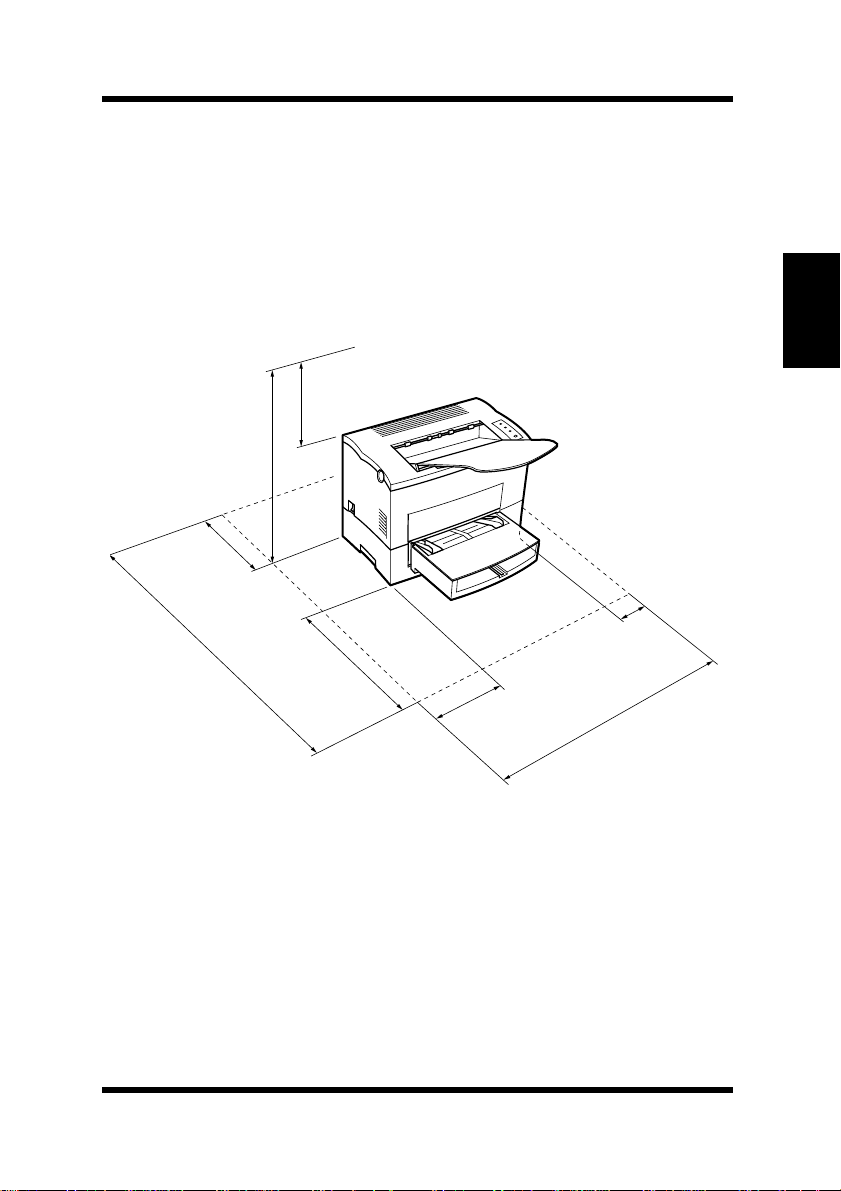
Be sure to provide space around the printer as indicated below, to
ensure easier printer operation, paper and toner replacement, and
maintenance.
24-3/4" (632 mm)
or more
* 29-1/2
** 34-1/4
40-1/2
(1,028 mm) or more
***46-1/2
(746 mm)
"
or more
(867 mm)
"
or more
6" (150 mm)
or more
***11-3/4" (300 mm)
or more
"
"
(1,178 mm) or more
11-3/4" (300 mm)
or more
23-1/2
"
(600 mm)
or more
11-3/4
"
(300 mm)
or more
4
"
(100 mm)
or more
33
(836 mm)
"
or more
Chapter 2
Setting-up
* When equipped with an optional second cassette unit.
** When equipped with an optional third cassette unit.
*** When equipped with an optional duplex unit.
2-3
Page 34

Operational Precautions
Operational Precautions
Note the following important precautions whenever using the printer.
Operating Environment
The following describes the operating environment required when
using the printer.
Chapter 2
• Temperature: 10°C to 35°C (50°F to 95°F) with fluctuation of
10°C (18°F) per hour
• Humidity: 15% to 85% with fluctuation of 20% per hour
Setting-up
Printer
The following describes precautions for using the printer.
• Never turn the printer off or open any of its covers during a print
operation.
• Never place flammable gasses, liquids or objects that generate
magnetic forces near the printer.
• When unplugging the power cord, always grasp the plug and never
pull on the cord. A damaged cord creates the danger of fire or electrical shock.
• Never touch the power cord when your hands are wet. Doing so
creates the danger of electrical shock.
• Always unplug the power cord before moving the printer. Failure
to do so can damage the power cord, creating the danger of fire or
electrical shock.
• Always unplug the power cord if you do not plan to use the printer
for a long time.
• Never try to remove any secured panel or cov er. The interior of the
printer contains high-voltage circuitry which creates the danger of
electrical shock when exposed.
2-4
Page 35

Operational Precautions
• Never try to modify the printer. Doing so creates the danger of f ire
or electrical shock.
• Never place any heavy objects on the power cord, pull on it or
bend it. Doing so creates the danger of fire or electrical shock.
• Always make sure the printer is not placed on the electrical cord or
the communications cables of any other electrical equipment. Also
make sure that cords and cables do not get into the printer’s mechanism. Any of these conditions create the danger of malfunction
and fire.
• Always take care so that paper clips, staples, or other small pieces
of metal do not get into the printer through its vents or other openings. Such objects create the danger of fire or electrical shock.
• Do not allow water or other liquids to spill on or near the printer.
Fire or electrical shock can occur should water or liquid come into
contact with the printer.
• Should liquid or any piece of metal accidently get inside the
printer, immediately turn it off, unplug the po wer cord, and contact
Minolta Technical Support. Failure to take this immediate action
creates the danger of fire or electrical shock.
Chapter 2
Setting-up
• Whenever the printer emits unusually high amounts of heat,
smoke, an unusual odor, or noise, immediately turn it off, unplug
it, and contact Minolta Technical Support. Failure to take this
immediate action creates the danger of fire or electrical shock.
Note
• Be sure to locate the printer in a well-ventilated location. A minimal
amount of ozone is generated during normal operation of this printer.
Because of this, an unpleasant odor may result when the printer is used
for extensive printing in a poorly ventilated area. For comfortable, and
safe operation, be sure to locate the printer in a well-ventilated area.
2-5
Page 36

Operational Precautions
Printer Supplies
Note the following precautions when handling printer supplies such as
the imaging cartridge, and paper.
Chapter 2
Setting-up
• Avoid storing printer supplies in the following locations:
✓Areas subjected to direct sunlight. Additionally, the imaging
cartridge must be protected from fluorescent light.
✓Areas exposed to open flame.
✓Areas subjected to high humidity.
✓Areas subjected to large amounts of dust.
• Keep paper that has been removed from its wrapper, but not yet
loaded onto the printer tray , in a sealed plastic bag and store it in a
cool, dark location.
• Only use imaging cartridges that are expressly specified for this
printer.
• Keep supplies out of the reach of children.
• Should your hands become soiled with toner, immediately wash
them with soap and water.
Note
• Whenever you remove the
diately wrap it with a cloth to protect it from overexposure to light.
imaging cartridge
from the printer, imme-
2-6
Page 37
Setting-up
Setting-up
See the separate Quick Guide for Installation and Reference that comes
with the printer before unpacking.
Set-up the printer according to the following instructions.
Note
• Always use a shielded interface cable. Use of an unshielded cable can
result in radio interference with data.
• Keep all the boxes and packing materials that the printer comes in for
later use when transporting the printer.
Chapter 2
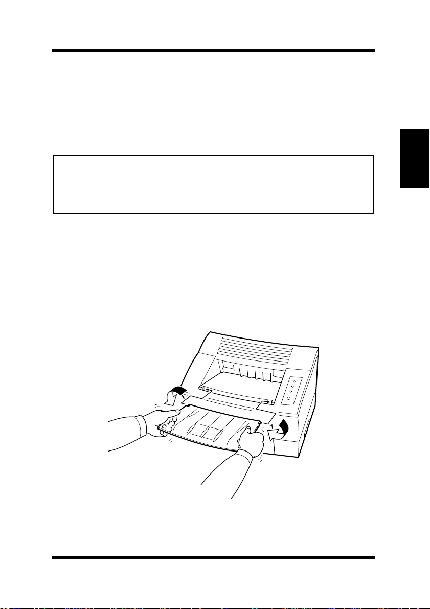
Installing the Face-Down Tray
With both hands, gently bend the face-down tray inwards and insert
one of its tabs into its holder on the upper portion of the printer.
Continue to bend the face-down tray so that it curves enough for the
second tab to fit into its holder and release the tray into position.
Setting-up
2-7
Page 38
Setting-up
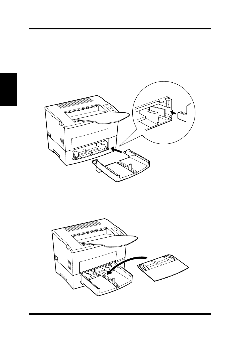
Installing Tray 1
Chapter 2
Setting-up
Using the left and right slots in the printer as guides, gently push
1
Tray 1 until it cannot be inserted any further (as shown in the
illustration).
Attach the tray cover onto Tray 1.
2
2-8
Page 39
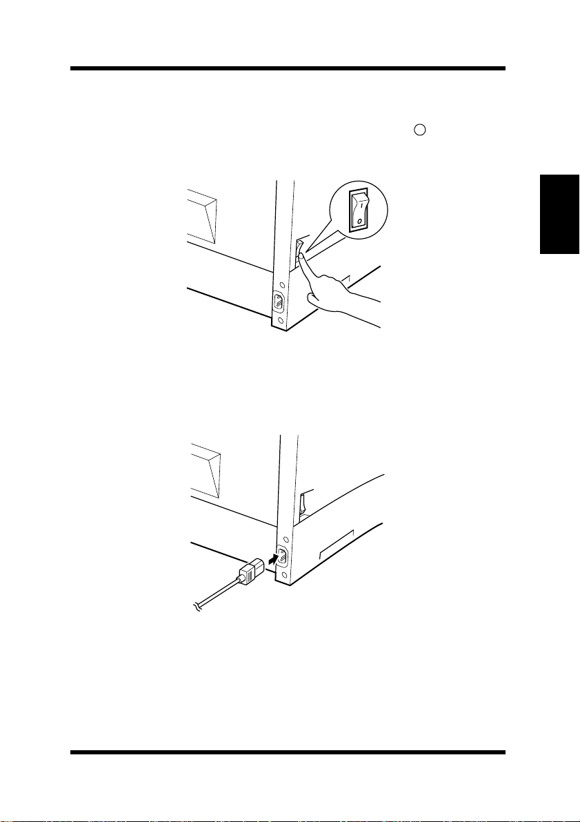
Connecting the Power Cord
Make sure that the printer’s power switch is in the (Off) posi-
1
tion.
Connect one end of the power cord that comes with the printer to
2
the power cord socket. Plug the other end into a power outlet.
Setting-up
Chapter 2
Setting-up
2-9
Page 40
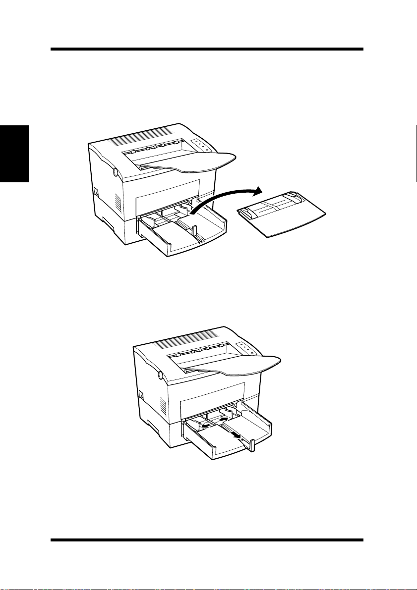
Setting-up
Loading Paper
Chapter 2
Setting-up
Remove the tray cover from Tray 1.
1
Open all three paper size guides.
2
2-10
Page 41
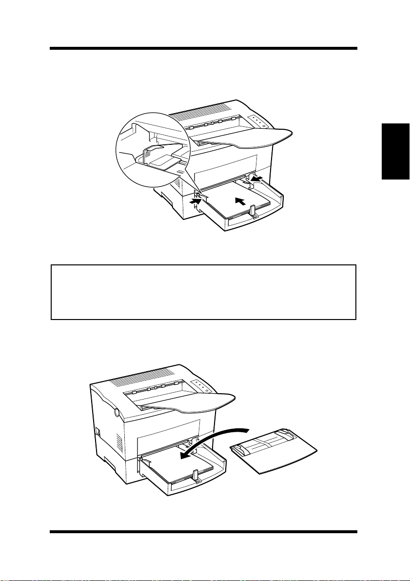
Setting-up
Place the paper stack onto the tray , print-side up. Secure the stack
3
by adjusting the paper size guides.
Note
• A maximum level mark on the
can stack paper on
than this mark.
• See pages 4-56 and 5-7 for details on making settings for
Tray 1
paper size guide
. Make sure that paper is stacked no higher
shows how high you
Tray 1
Chapter 2
Setting-up
.
Replace the tray cover onto Tray 1.
4
2-11
Page 42
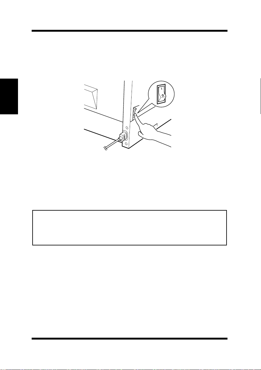
Setting-up
Turning On the Printer
After connecting the printer to a power outlet, press the power switch
to turn it on.
Chapter 2
Setting-up
Turning on the printer causes all the indicators on the control panel to
light, which indicates that the printer is warming up. In about 23
seconds only the READY indicator remains lit, indicating that the
printer is ready to print.
Note
• The printer automatically enters a power saving mode if it receives no
print commands for about 15 minutes. Whenever the printer receives a
print command while in the power saving mode, it starts to warm up
again and takes about 23 seconds before it is ready to print.
2-12
Page 43
Setting-up
Testing the Printer
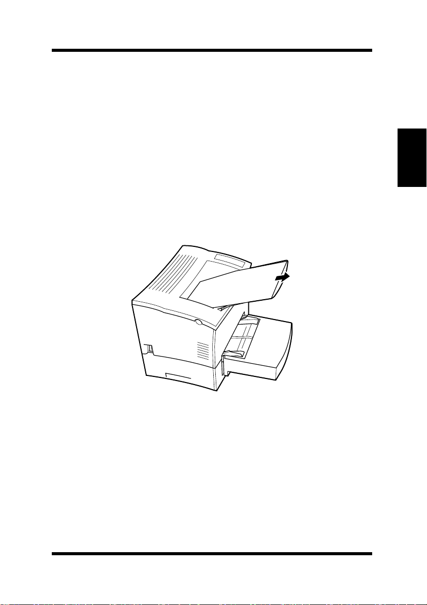
Before connecting to a computer, perform the following procedure to
print a Configuration Page and see if the printer is working correctly.
Place the paper onto Tray 1.
1
Make sure that both the PAPER and ERROR indicators are off,
2
and the READY indicator is on. This indicates there is no existing error condition and no data remaining to be printed.
Briefly press the panel button to start printing the Configuration
3
Page.
Chapter 2
Setting-up
2-13
Page 44
Setting-up
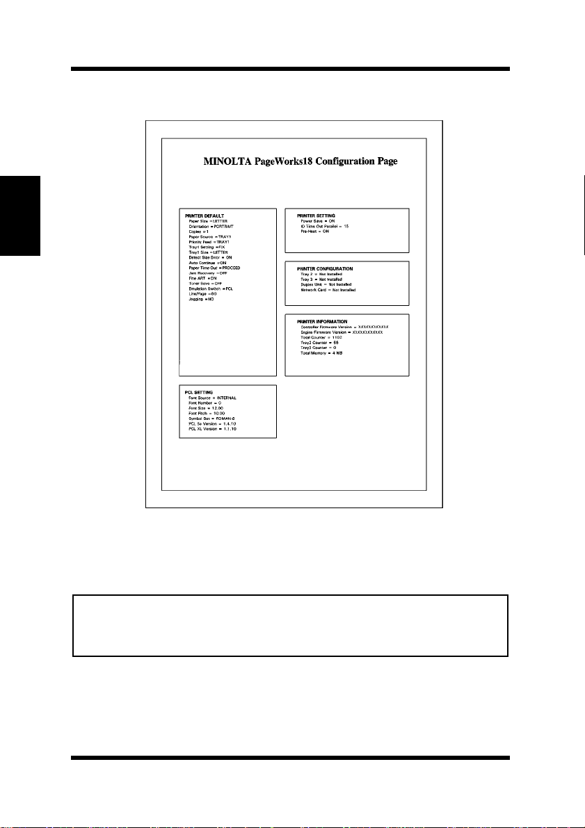
Sample Configuration Page
Chapter 2
Setting-up
Note
• See Chapter 7 of this manual for information on what to do if the Configuration Page does not print when you press the panel button.
• The Configuration Page can be printed on Letter size paper only.
2-14
Page 45
Connecting to a Computer
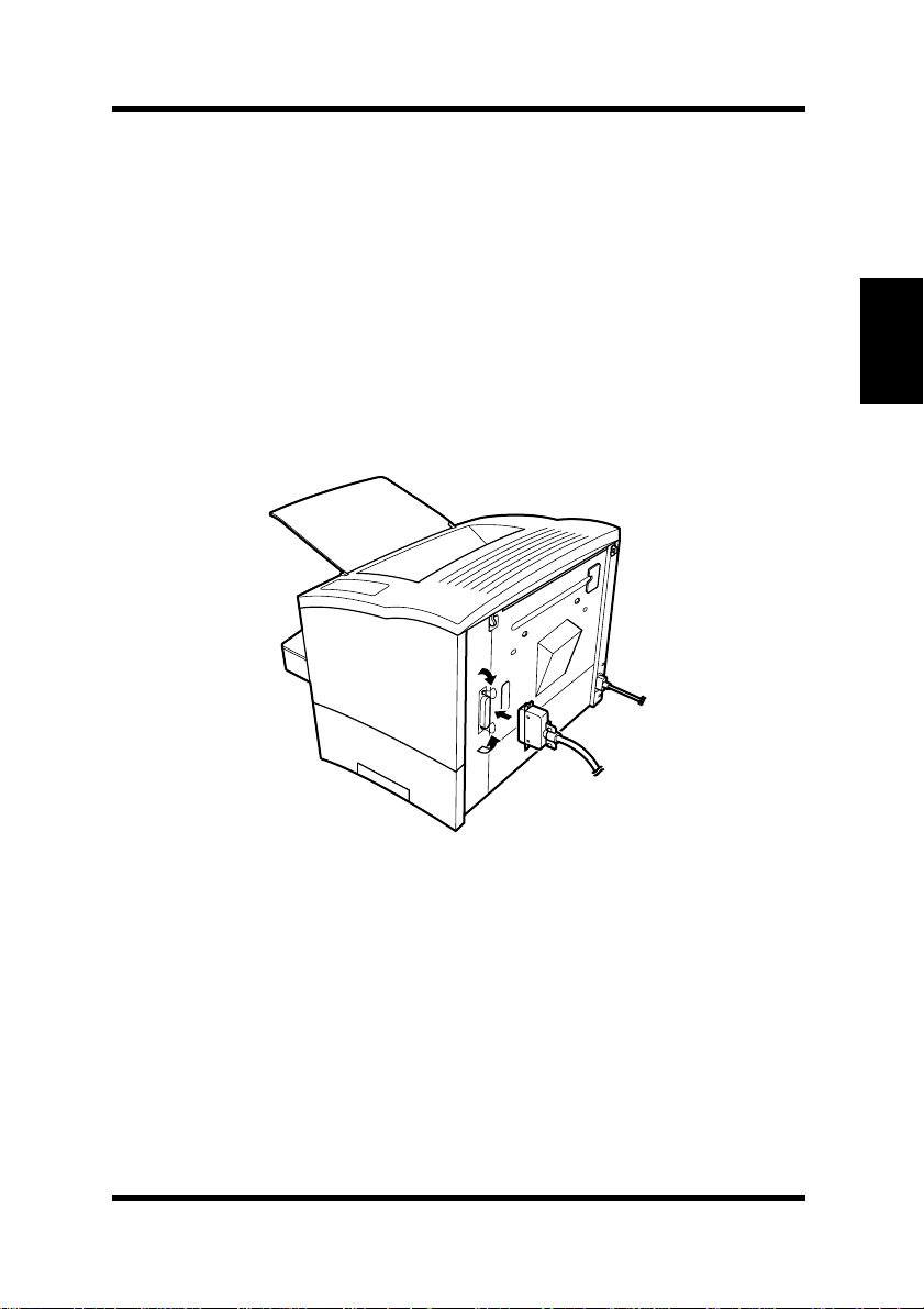
Make sure that the printer and the computer you are connecting it
1
to are both turned off.
Connect one end of the interface cable to the parallel port of the
2
computer.
Connect the other end of the cable to the parallel connector on the
3
back of the printer. Secure the cable using the two clips on the
parallel connector.
Setting-up
Chapter 2
Setting-up
See page 8-7 of this User’s Manual for cable specifications and pin
assignments.
2-15
Page 46

Options
Options
This section describes the optional items that are available for this
printer:
Unit
the
SIMM (Single In-line Memory Module)
Chapter 2
Setting-up
Many errors caused by data overload can be avoided by installing
additional memory into the printer.
This printer comes with 4 MB of memory. You can increase memory
capacity to up to 64 MB by installing an optional 1, 2, 4, 8, 16 or
32 MB SIMM into one or both of the two memory connectors located
inside of the printer.
Memory SIMM(s), Duplex Unit, Second Paper Cassette
Third Paper Cassette Unit, Adobe PostScript ROM-SIMM
,
Network Interface Card
.
, and
Note
• Memory capacity can be increased to 64 MB by installing two 32 MB
SIMMs into the printer. (However, it will first be necessary to remove
the 4 MB SIMM that comes installed in the printer.) The successful
installation of the expansion memory can be confirmed by printing a
Configuration Page.
Installing the Optional SIMM
Warning
• Electric shock hazard! Do not remove any cover of the printer that is
not directly specified for removal in the User’s Manual.
Turn off the printer and unplug the power cord.
1
Disconnect the parallel cable from the printer.
2
Press the top cover release button and open the top cover.
3
2-16
Page 47
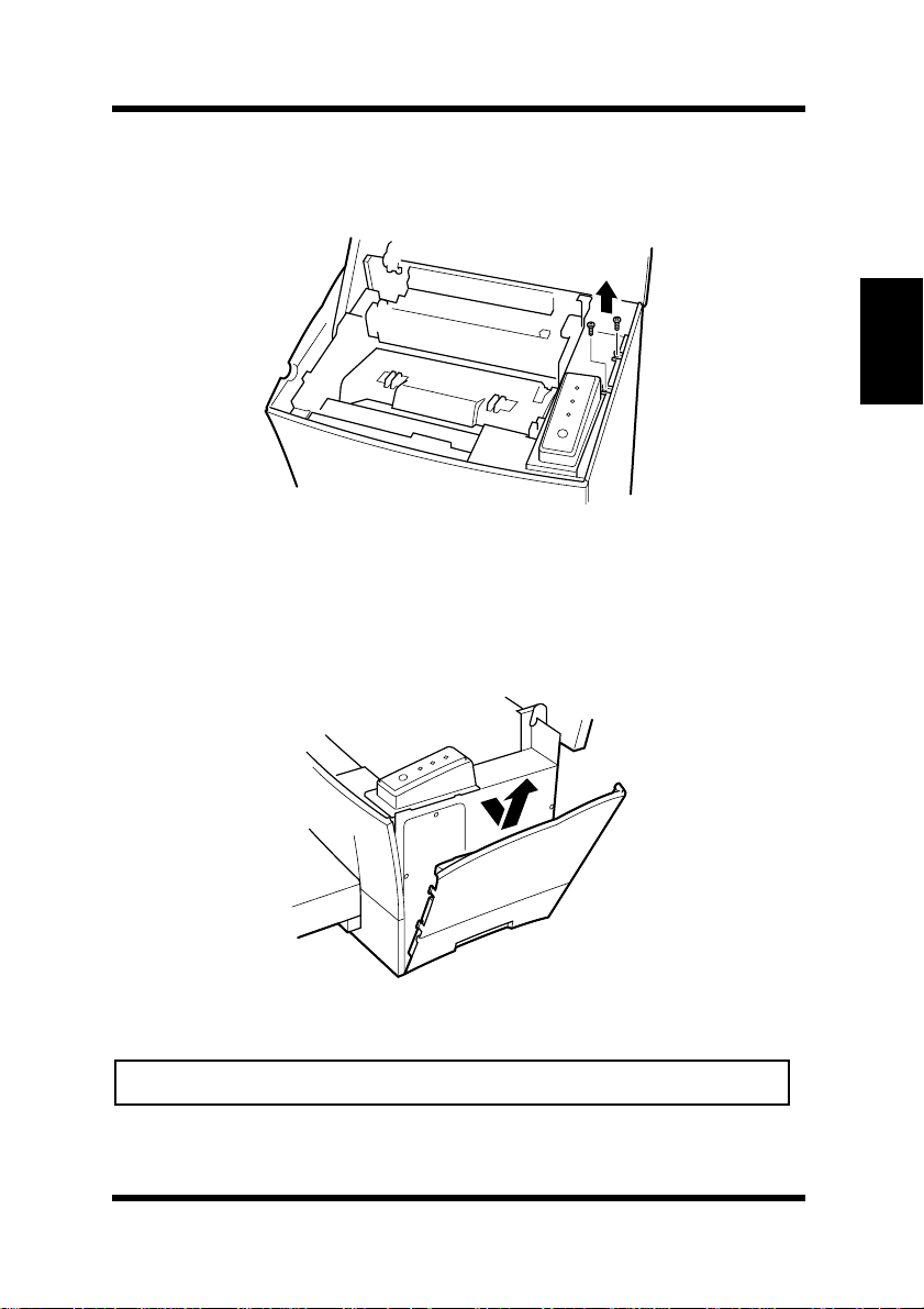
Using a screwdriver, loosen and remove the two screws that
4
secure the exterior side cover to the printer.
Clips secure the exterior side cover from the inside of the printer.
5
Gently maneuver the exterior side cover until the clips release
(see illustration).
Options
Chapter 2
Setting-up
Caution
• Do not touch any part of the main circuit inside of the printer.
2-17
Page 48
Options
Chapter 2
Setting-up
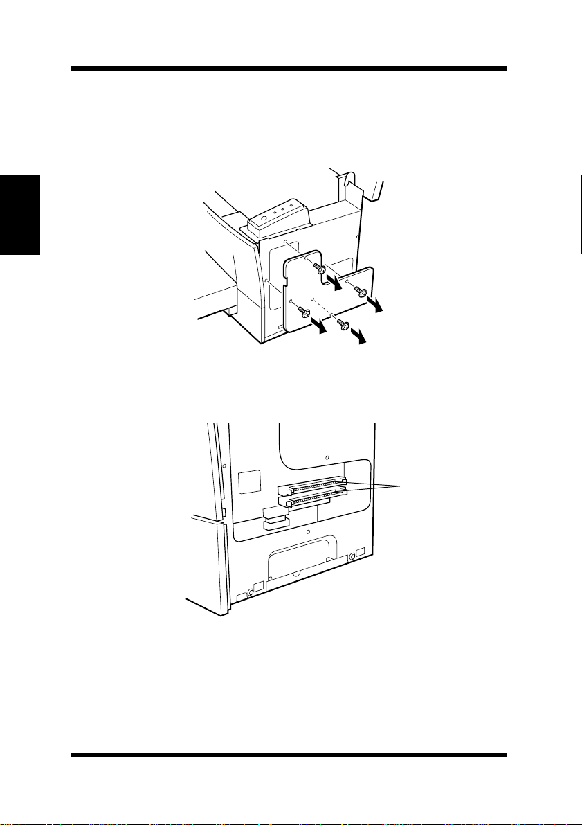
With the exterior side cover removed, the internal side cover of
6
the printer is exposed. With the screwdriver, loosen and remove
the four screws that secure the internal side cover.
Remove the internal side cover to expose the main circuit.
7
2-18
SIMM sockets
Page 49
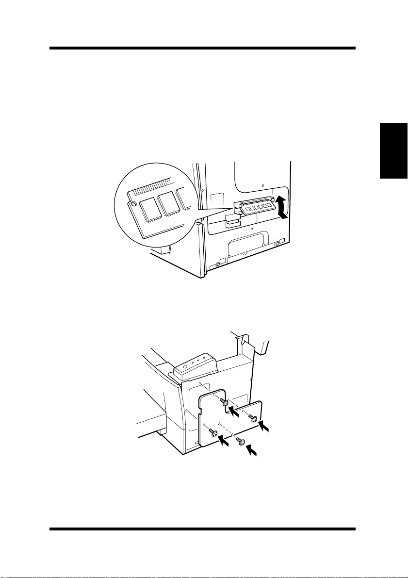
Being careful not to touch the connection points along the edge of
8
the SIMM, insert the SIMM into one of the available sockets on
the main circuit.
• Insert the SIMM at an angle as shown and gently swing it into
the socket.
• Apply pressure until the SIMM locks into place.
Replace the internal side cover using the four screws.
9
Options
Chapter 2
Setting-up
2-19
Page 50
Options
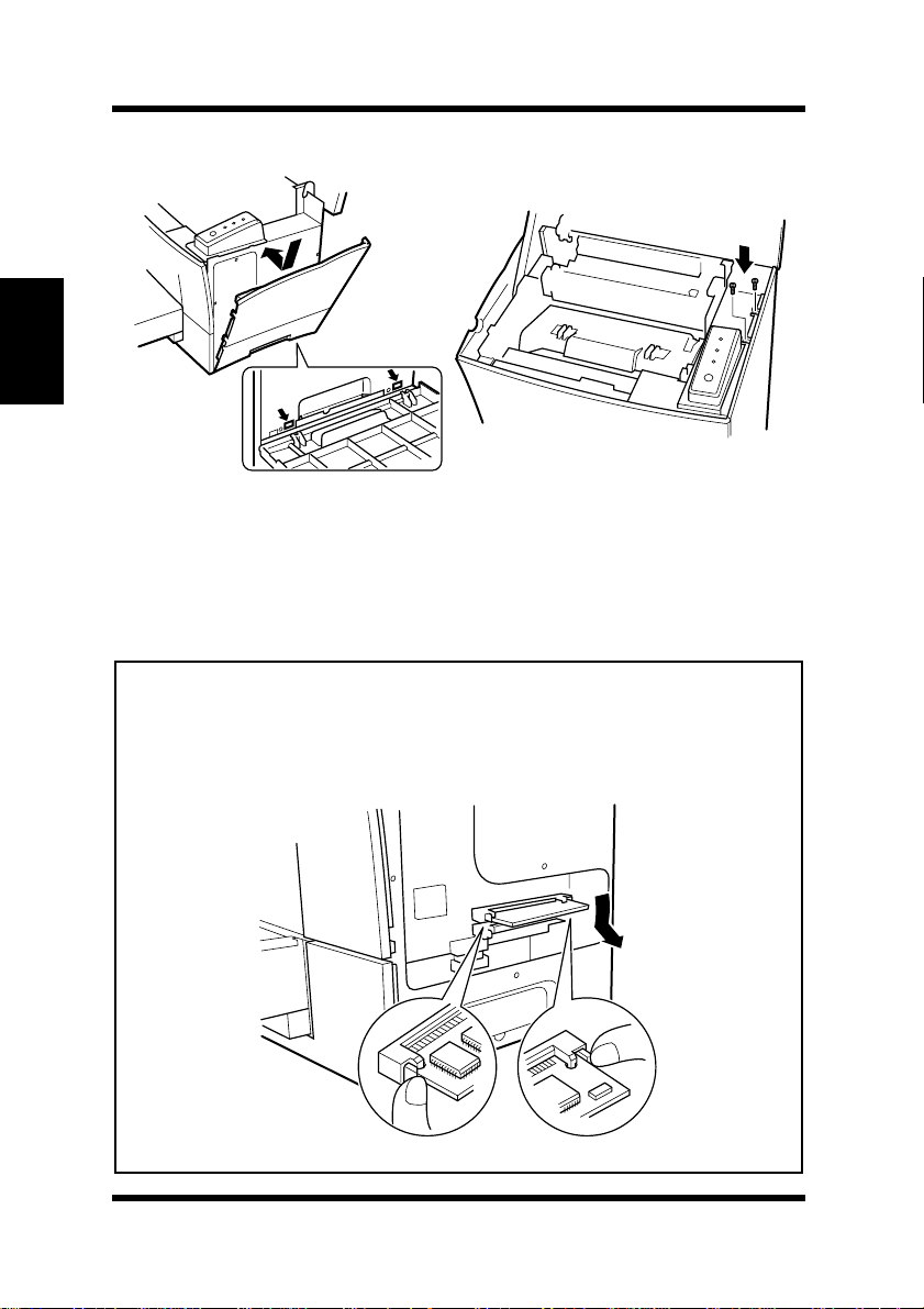
10
Chapter 2
Setting-up
11
Replace the external side cover using the two screws.
Print a Configuration Page (page 2-14) and check to make sure
that the “Total Memory” item correctly shows the increase in
memory capacity. If it does not, repeat the above steps making
sure that the SIMM is installed correctly.
Note
• T o release the SIMM from the socket, push out on the taps on each side
of the socket.
• After installation of the SIMM, reset the Printer Memory Setting to
reflect the new memory capacity (see page 4-60).
2-20
Page 51
Options
Duplex Unit
Your printer supports double-sided printing if the optional duplex unit
is installed. Double-sided documents can be generated for binding
along either the short or long edges of the paper through the printer
software. For more information, refer to page 3-15.
• Take the duplex unit out of the shipping box.
• Remove the plastic bag and all shipping materials.
• Turn the printer off and then disconnect the power cord and interface cable from the printer.
Installing the Duplex Unit
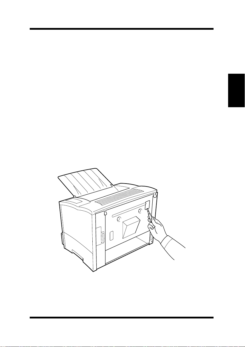
With a scre wdri ver or similar instrument, remo v e the flat clip that
1
is attached to the back of the main unit of the printer.
Chapter 2
Setting-up
2-21
Page 52
Options
Chapter 2
Setting-up
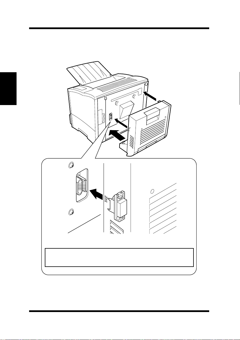
Align the “L” shaped duplex unit to the back of the main unit of
2
the printer so that the bottom of the “L” is inside of the opening at
the bottom of the printer.
2-22
Note
• Make sure that the connector of the unit is inserted into
the printer securely.
Page 53
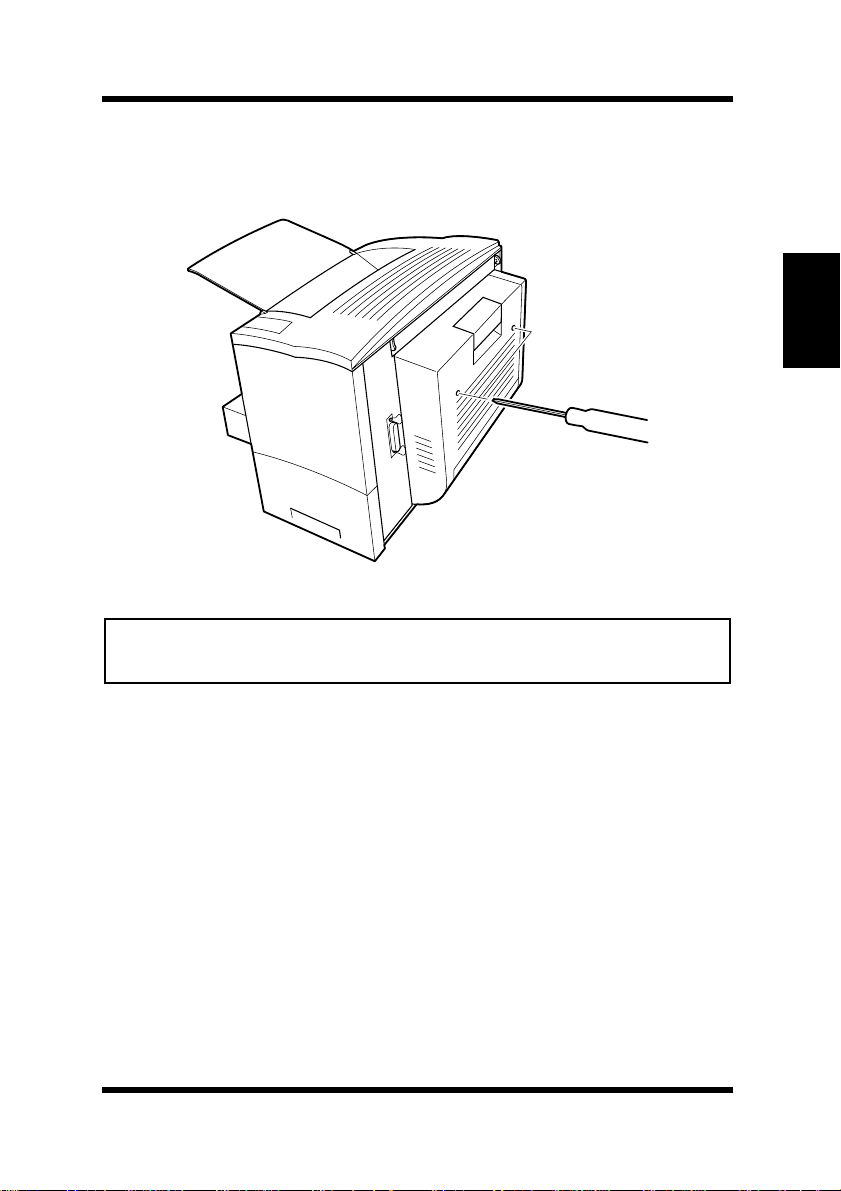
With one hand holding the duplex unit in position, use a Phillips
3
screwdriv er to tighten the scre ws that are permanently attached to
the back of the duplex unit.
Note
• Hold up the
secured to the printer with the screws.
duplex unit
with your hand during installation until it is
Options
Chapter 2
Setting-up
Connect the power cord to the printer and then turn the printer on.
4
See “Connecting the Power Cord”, page 2-9.
See “Turning On the Printer”, page 2-12.
Generate a configuration page to verify that duplex unit is listed
5
under the Printer Configuration item.
See “Testing the Printer”, page 2-13.
PRINTER CONFIGURATION
Tray 2 = Not Installed
Tray 3 = Not Installed
Duplex Unit = Installed
PostScript = Not Installed
Network Card = Not Installed
2-23
Page 54
Options
Second/Third Paper Cassette Unit
You can increase the paper-holding capacity of your printer by
installing an optional second/third paper cassette unit. Each paper
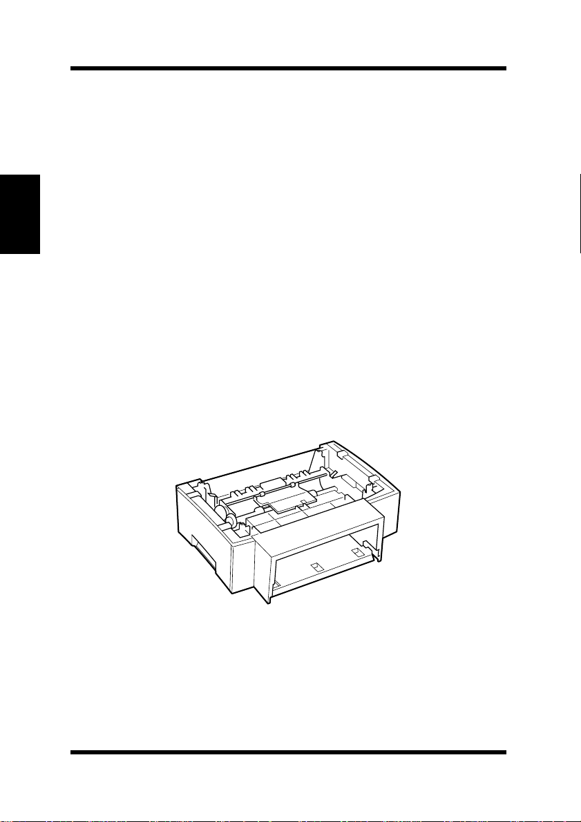
cassette unit can hold up to 500 sheets of paper. The second and third
paper cassette units are interchangeable and can increase paper-
holding capacity to 1,000 sheets when installed together.
Chapter 2
Installing the Optional Second/Third Paper Cassette
Unit
Setting-up
• Take the paper cassette unit out of the shipping box.
• Remove the plastic bag and all shipping materials.
• Turn the printer off and then disconnect the power cord and interface cable from the printer.
Place the paper cassette unit in the location you have chosen
1
(see page 2-1 “Selecting a Location for the Printer”).
Pull out the paper tray.
2-24
Page 55
Options
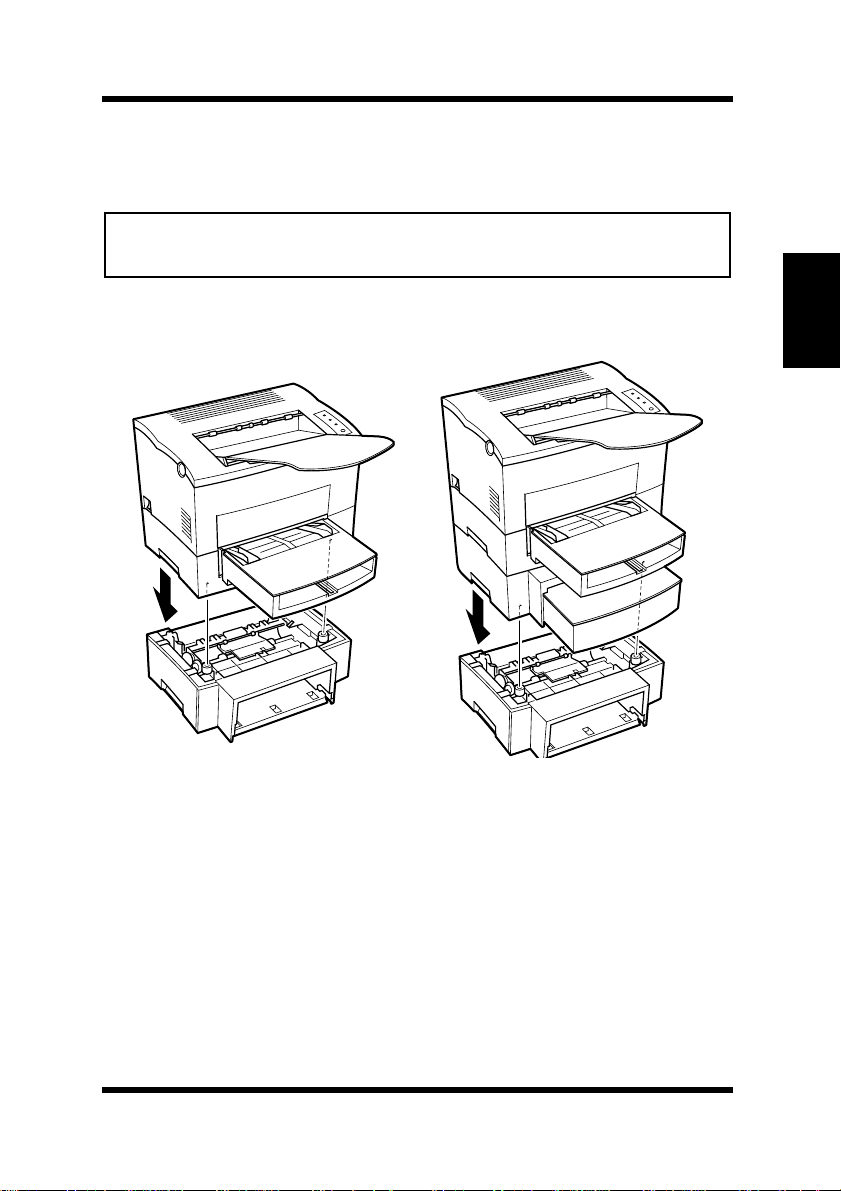
Set the printer onto the paper cassette unit using the coupling
2
pins as a guide.
Note
• The printer weighs approximately 18 kg (39.7 lbs.). Two people are
recommended to lift it when necessary.
Second paper cassette unit Third paper cassette unit
Chapter 2
Setting-up
2-25
Page 56
Options
Chapter 2
Setting-up
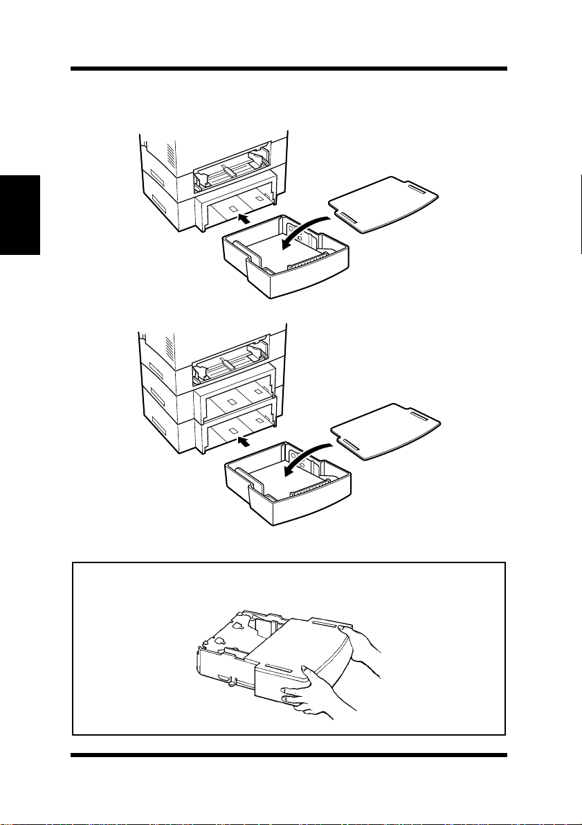
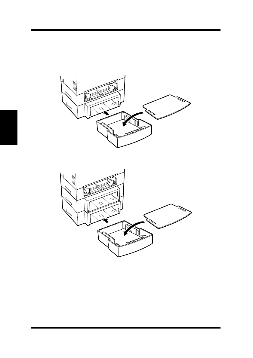
Insert Tray 2 or Tray 3 into the paper cassette unit.
3
Tray 2
Tray 3
Note
• Be sure to use both hands whenever
from or inserted into the
paper cassette unit
2-26
T ray 2 or T ray 3
.
is being removed
Page 57

Connect the power cord to the printer and then turn the printer on.
4
See “Connecting the Power Cord”, page 2-9.
See “Turning On the Printer”, page 2-12.
Generate a configuration page to verify that Tray 2 or Tray 3 is
5
listed under the Printer Configuration item.
See “Testing the Printer”, page 2-13.
Options
PRINTER CONFIGURATION
Tray 2 = Installed
Tray 3 = Installed
Duplex Unit = Not Installed
PostScript = Not Installed
Network Card = Not Installed
Chapter 2
Setting-up
2-27
Page 58
Options
Adobe PostScript ROM-SIMM
This printer is equipped with a socket for the installation of an Adobe
PostScript ROM-SIMM. This ROM-SIMM enables the printer to
support the PostScript page description language.
Chapter 2
Warning
• The Adobe PostScript ROM-SIMM is easily damaged by static electricity. Touch a metal object before you touch the ROM-SIMM.
• Take the Adobe PostScript ROM-SIMM out of the shipping box.
• Turn the printer off and then disconnect the power cord and interface cable from the printer.
Setting-up
Installing the Optional Adobe PostScript ROM-SIMM
Warning
• Electric shock hazard! Do not remove any cover of the printer that is
not directly specified for removal in the User’s Manual.
Turn off the printer and unplug the power cord.
1
Disconnect the parallel cable from the printer.
2
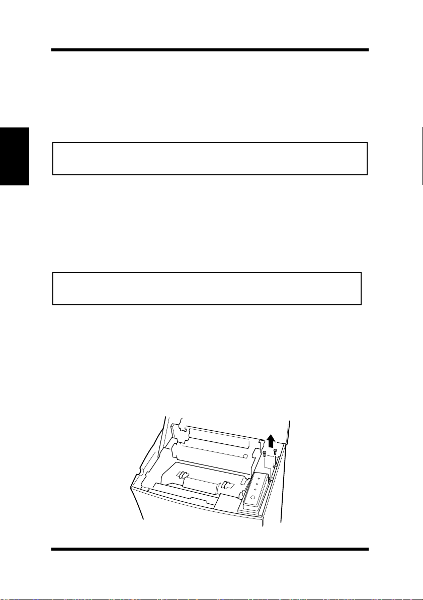
Press the top cover release button and open the top cover.
3
Using a screwdriver, loosen and remove the two screws that
4
secure the exterior side cover to the printer.
2-28
Page 59
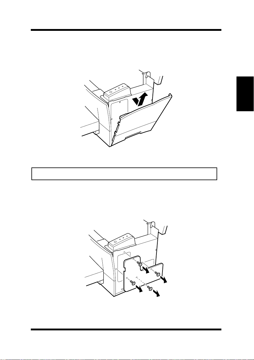
Clips secure the exterior side cover from the inside of the printer.
5
Gently maneuver the exterior side cover until the clips release
(see illustration).
Caution
• Do not touch any part of the main circuit inside of the printer.
With the exterior side cover removed, the internal side cover of
6
the printer is exposed. With the screwdriver, loosen and remove
the four screws that secure the internal side cover.
Options
Chapter 2
Setting-up
2-29
Page 60
Options
Chapter 2
Setting-up
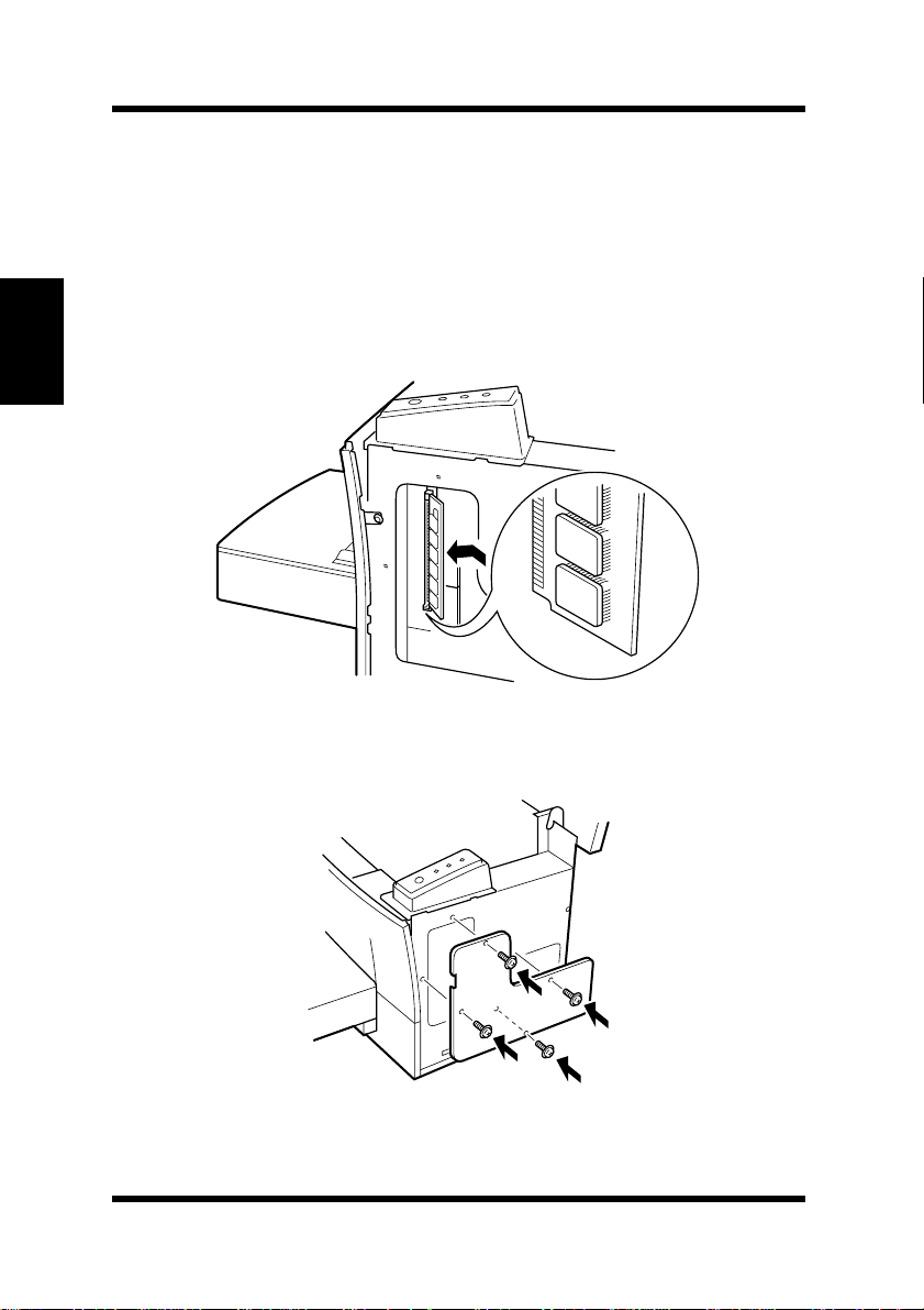
Remove the internal side cover to expose the main circuit.
7
Being careful not to touch the connection points along the edge of
8
the SIMM, insert the SIMM into the socket of the main circuit.
• Insert the SIMM at an angle as shown and gently swing it into
the socket.
• Apply pressure until the SIMM locks into place.
Replace the internal side cover using the four screws.
9
2-30
Page 61
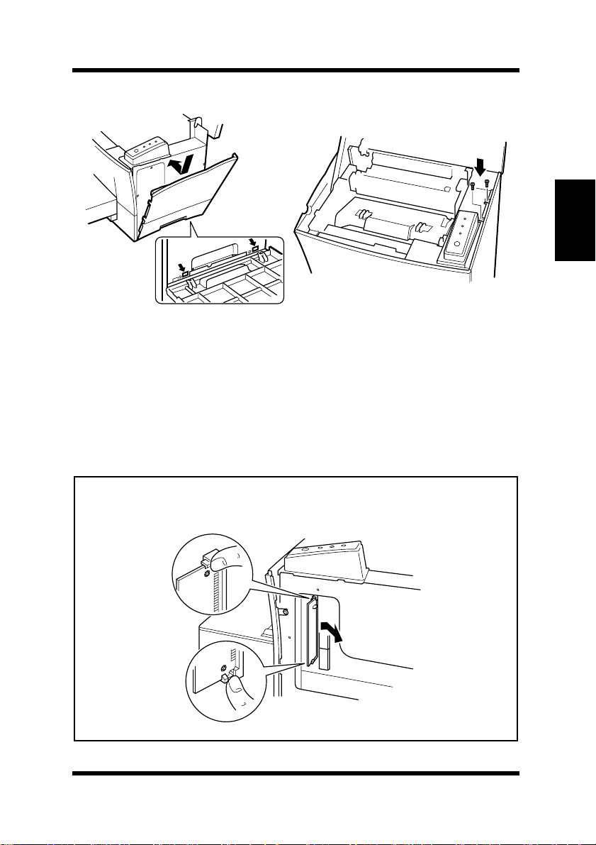
Replace the external side cover using the two screws.
10
Connect the power cord to the printer and then turn the printer on.
11
See “Connecting the Power Cord”, page 2-9.
See “Turning On the Printer”, page 2-12.
Generate a configuration page to verify that PostScript is listed
12
under the Printer Configuration item.
See “Testing the Printer”, page 2-13.
Options
Chapter 2
Setting-up
Note
• T o release the SIMM from the socket, push out on the taps on each side
of the socket.
2-31
Page 62

Options
PRINTER CONFIGURATION
Chapter 2
Setting-up
Tray 2 = Not Installed
Tray 3 = Not Installed
Duplex Unit = Not Installed
PostScript = Installed
Network Card = Not Installed
2-32
Page 63
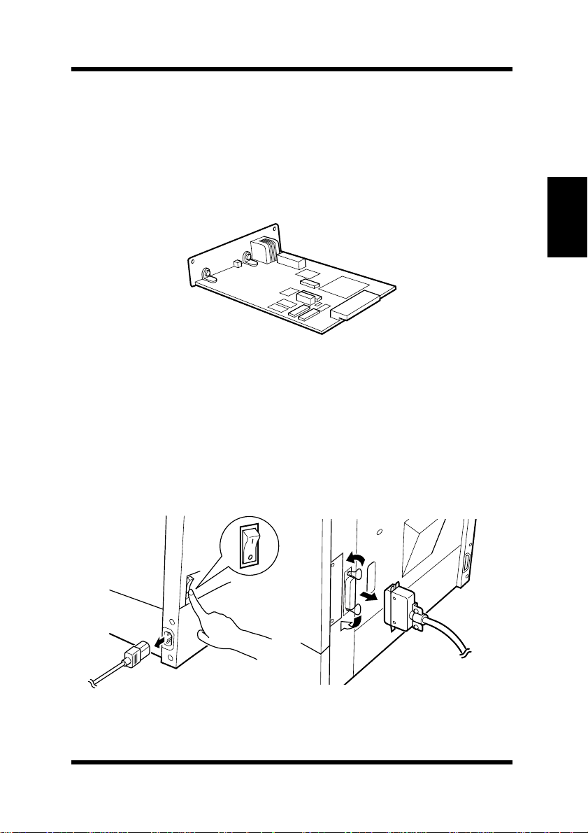
Options
Network Interface Card (NIC)
There are two optional network interface cards that are supported by
this printer:
select should be determined according to the requirements of your
network environment. F or details, please see the User’ s Manual for the
Network Interface Card.
* This illustration shows the optional 10/100BaseT Network Interface
Card.
10/100BaseT
Installing the Optional Network Interface Card
and
10Base2
. The NIC option that you
Chapter 2
Setting-up
Turn the printer off and unplug the power cord from the printer.
1
Disconnect the cable from the interface connector.
2-33
Page 64
Options
Chapter 2
Setting-up
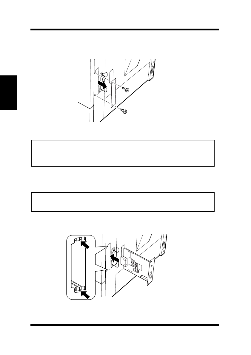
Remove the screw that secures the cover panel to the back of the
2
printer. Remove the cover panel.
Note
• Make sure that you do not misplace the cover panel or screws when
you remove them. The screws will be used after the optional NIC is
installed.
Take the NIC out of its carton.
3
Note
• When the NIC is taken out of its conductive bag or of f its mat, hold it
by its edges to avoid touching the terminals or the patterned surfaces.
Insert the NIC as shown in the diagram.
4
2-34
Page 65
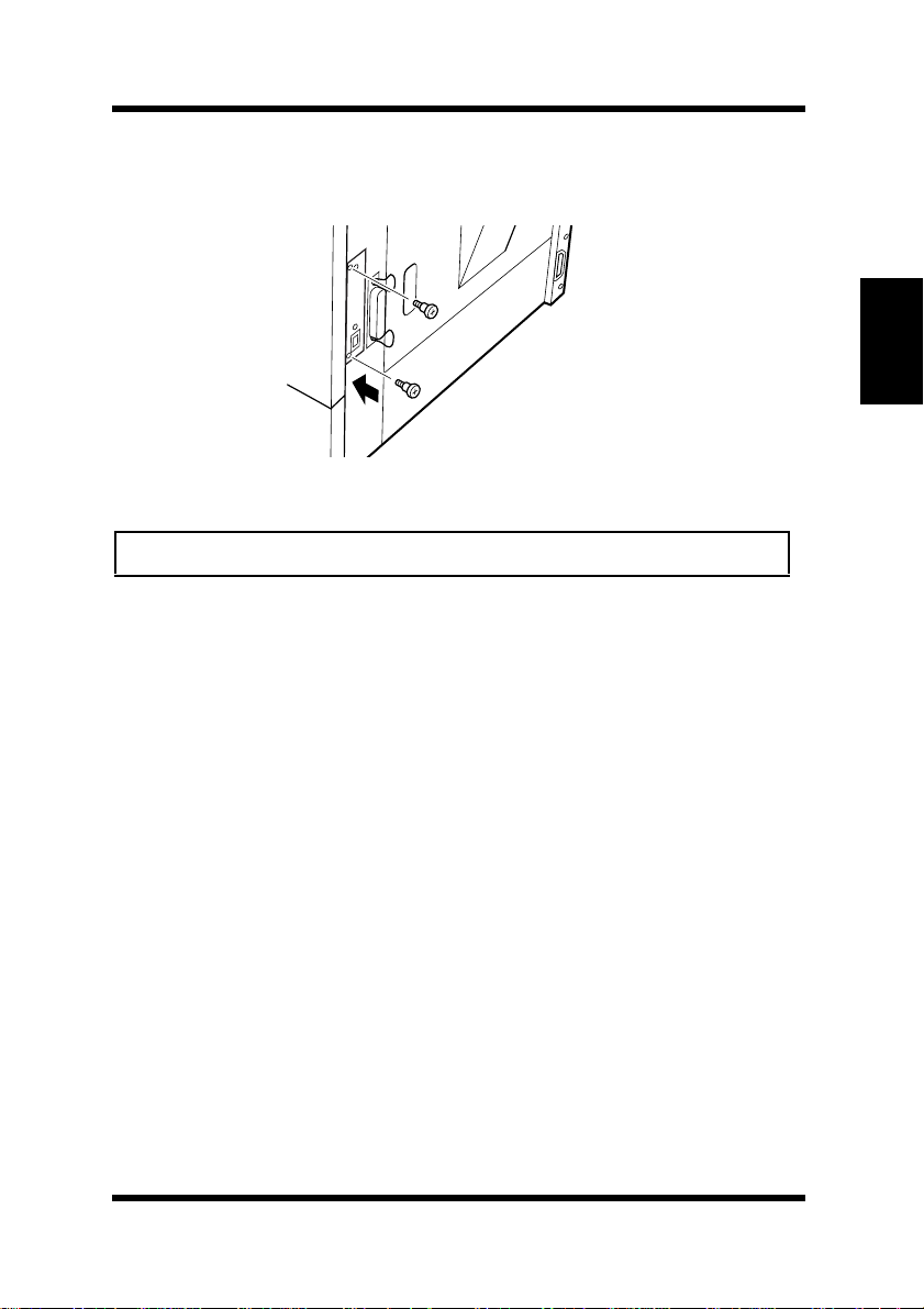
Secure the NIC into place using the same screws that were used
5
to hold the cover panel.
Options
Chapter 2
Note
• Follow the NIC’s installation procedure in reverse to remove the NIC.
Connect the power cord to the printer and then turn the printer on.
6
See “Connecting the Power Cord”, page 2-9.
See “Turning On the Printer”, page 2-12.
Generate a configuration page to verify that Network Card is
7
listed under the Printer Configuration item.
See “Testing the Printer”, page 2-13.
PRINTER CONFIGURATION
Tray 2 = Not Installed
Tray 3 = Not Installed
Duplex Unit = Not Installed
PostScript = Not Installed
Network Card = Installed
Setting-up
2-35
Page 66

MEMO
Chapter 2
Setting-up
Page 67

Chapter
Chapter 3
Using the Printer
3
Using the Printer
Page 68

Chapter 3
Using the Printer
Page 69
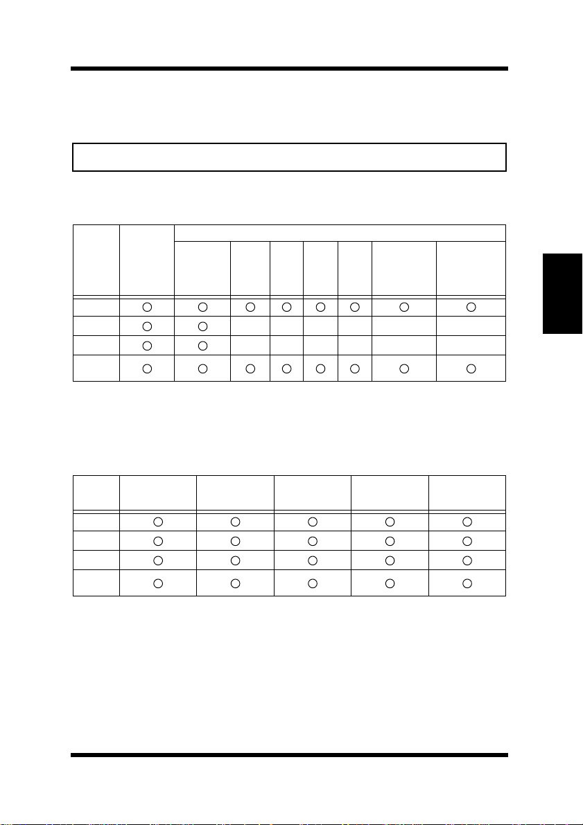
Paper
Caution
• This printer is designed to print on only the following types of paper.
Type
Paper
Paper
Feeding
Port
Feed Tray
Tray 1
Tray 2
Tray 3
Manual
Plain Paper
weighing:
60 to 90 g/m2
16 to 24 lbs.
Recycled
Paper
weighing:
60 to 90 g/m
16 to 24 lbs.
2
Transparency
Sheet
None
None
Special Paper
Labels Letter-
None None None None None
None None None None None
head
Envelopes
J-Post (Postcard ) size:
100 × 148 mm
4" × 5-3/4"
Thick Paper
weighing:
90 to 163 g/m
24 to 43 lbs.
Size
Standard size
Paper
Feeding
Port
Tray 1
Tray 2*
Tray 3*
Manual
Feed Tray
* Each of the five cassettes of Tray 2/Tray 3 support one of the five types of paper that are
compatible with this printer.
A4
210 × 297 mm
8-1/4" × 11-3/4"
JIS B5
182 × 257 mm
7-1/4" × 10"
Legal
216 × 356 mm
8-1/2" × 14"
Letter
216 × 279 mm
8-1/2" × 11"
Executive
184 × 267 mm
7-1/4" × 10-1/2"
2
Chapter 3
Using the Printer
3-1
Page 70
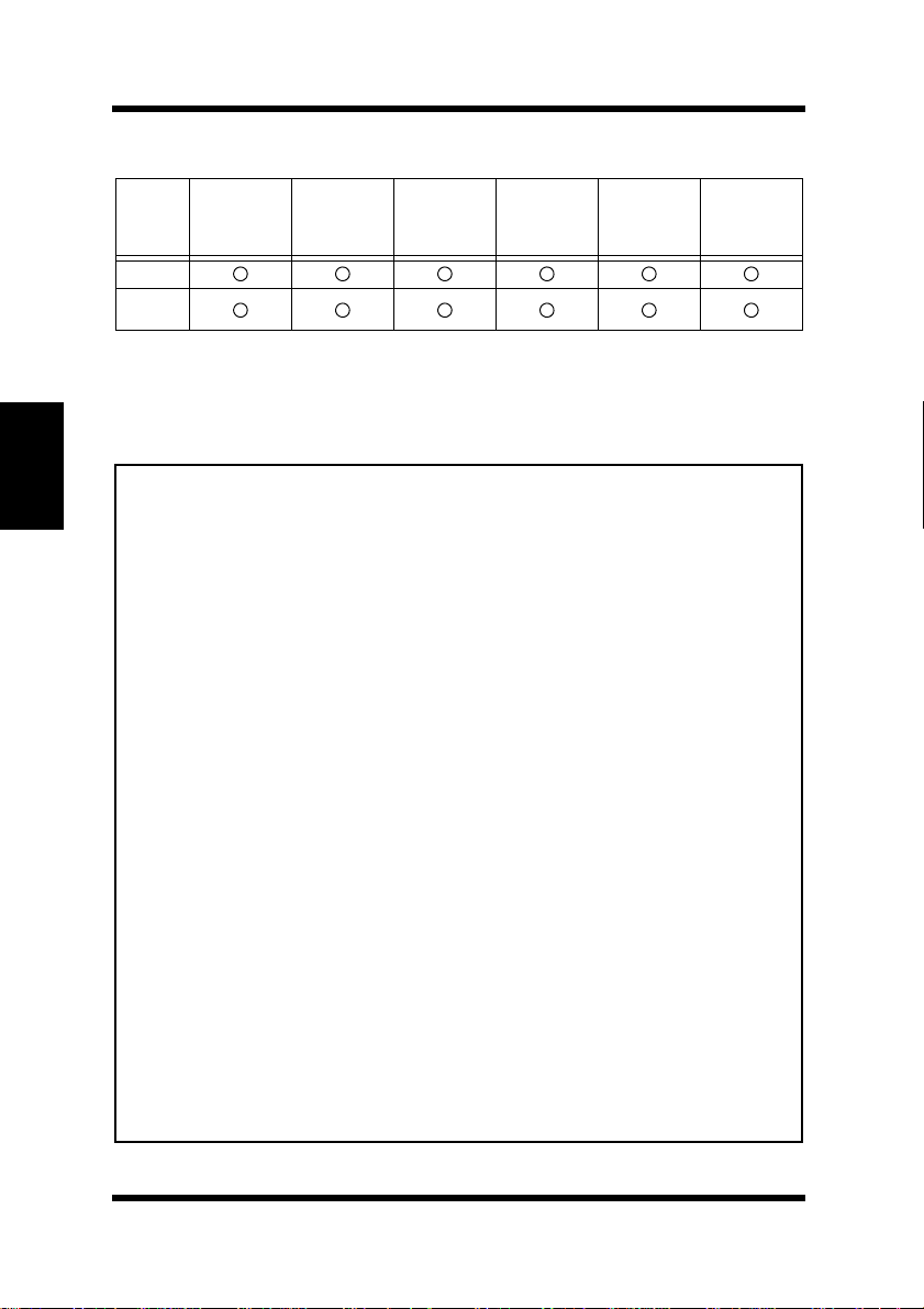
Paper
Envelopes and custom sizes (Tray 1 and Manual Feed T ra y)
Paper
Feeding
Port
Tray 1
Manual
Feed Tray
** Printing is possible only if
set to
Multiple Size
• Specialty paper is not supported for duplex printing.
Note
Chapter 3
Using the Printer
• Do not use the following types of paper to avoid reduced print quality,
a misfeed or a print failure.
✓
✓
✓
✓
✓
✓
✓
✓
✓
✓
✓
• Envelopes should meet the following requirements:
✓
✓
✓
✓
• Generally, envelopes perform well, but some types may wrinkle. We
strongly recommend testing any type of envelope before buying it in
large amounts.
• For more information, refer to “Loading Paper”.
Env. Com10
105 × 241mm
4-1/8" × 9-1/2"
Env. DL
110 × 220mm
4-5/16" × 8-11/16"
Tra y1 Setting
. (See pages 4-56 and 5-7).
Env. C5
162 × 229mm
6-3/8" × 9"
on the
Env. B5
176 × 250mm
6-15/16" × 9-7/8"
tab of the Printer Control Panel dialog is
Paper
Env. Monarc h
98 × 190mm
3-7/8"×7-1/2"
Custom
86 to 216
148 to 356mm
3-3/8"to 8-1/2" ×
3-1/2" to 14"
**
Paper already used in a thermal transfer printer or ink jet printer.
Paper that is too thin or too thick.
Paper folded, curled or torn.
Paper having binding holes or perforations.
Paper with surfaces that are too smooth or too rough or with varying
surfaces.
Paper having special coatings on their surfaces such as carbon
paper, heat-sensitive paper and pressure-sensitive paper.
Sheets of various sizes.
Paper not cut on right angles.
Paper bound by glue, staples or clips.
Paper affixed with labels which are easy to peel.
Post cards that are warped or bent.
Sharp folds and edges.
General mailing envelopes without seals on the glued portion.
Having flaps the full width of the envelope (unacceptable if the flap
is glued).
Wrinkle-free, no fasteners.
×
3-2
Page 71

Loading Paper
Loading Paper
There are two primary sources that can be used to feed paper into the
printer: Tray 1 and the manual feed tray.
Tray 1 is the standard source for supplying paper to the printer. Various
types and sizes of paper can be fed from this tray.
Tray 2/Tray 3 are available as optional paper sources. See the section
of this User’s Manual entitled “Loading P aper onto Tray 2/Tray 3” for
details on using these trays.
Whenever you are using special size paper, be sure to use the printer
driver installed on the computer to specify the printing area. You may
experience some variation in print quality when using special size
paper.
Always remember that paper storage conditions greatly affect print
quality. Store paper in its original package. Keep paper out of areas
subject to extreme temperatures or humidity.
Chapter 3
3-3
Using the Printer
Page 72
Loading Paper
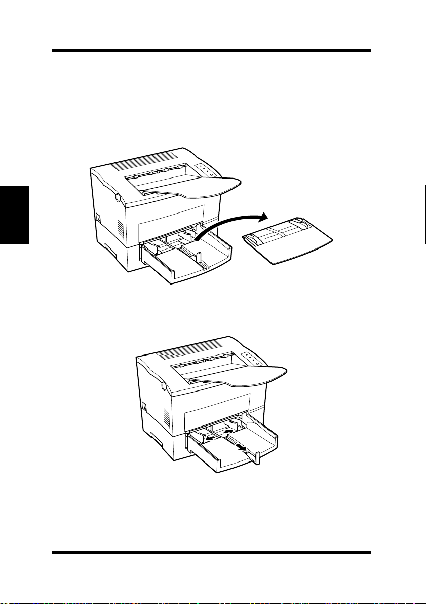
Loading Paper onto Tray 1
You can load up to 250 sheets of standard paper onto Tray 1. See page
3-1 for details on paper sizes and types.
Remove the tray cover from Tray 1.
1
Chapter 3
Open the paper size guides.
2
Using the Printer
3-4
Page 73
Loading Paper
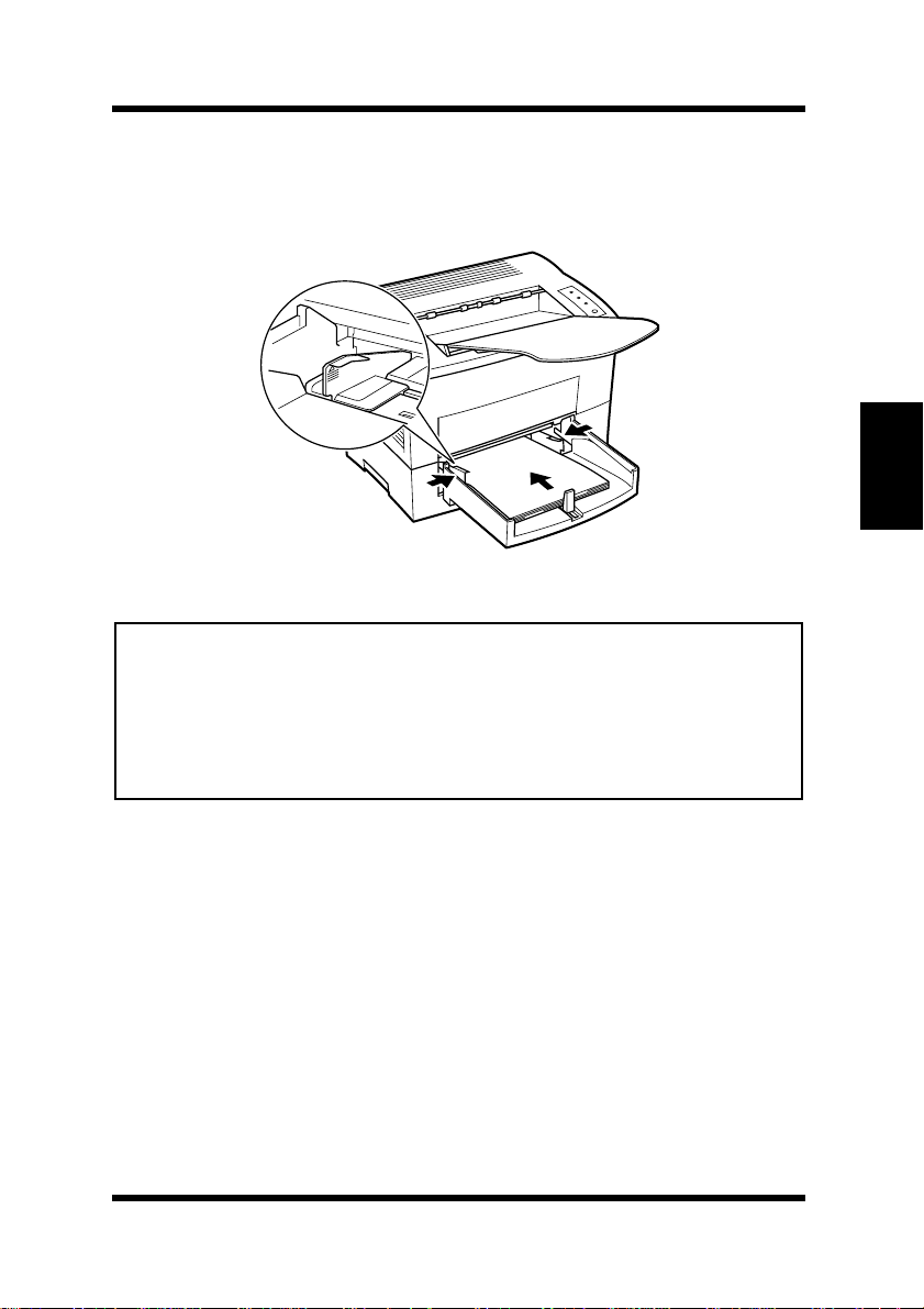
Place a stack of paper in the center of Tray 1. Adjust the paper
3
size guides so that both the left and the right sides of the paper
stack are secure.
Note
• A maximum level mark on the
can stack paper on
than this mark.
• Do not load additional paper until the paper currently loaded onto
is completely used.
1
• See pages 4-56 and 5-7 for details on making settings for
Tray 1
paper size guide
. Make sure that paper is stacked no higher
shows how high you
Tray 1
T ray
.
Chapter 3
Using the Printer
3-5
Page 74
Loading Paper
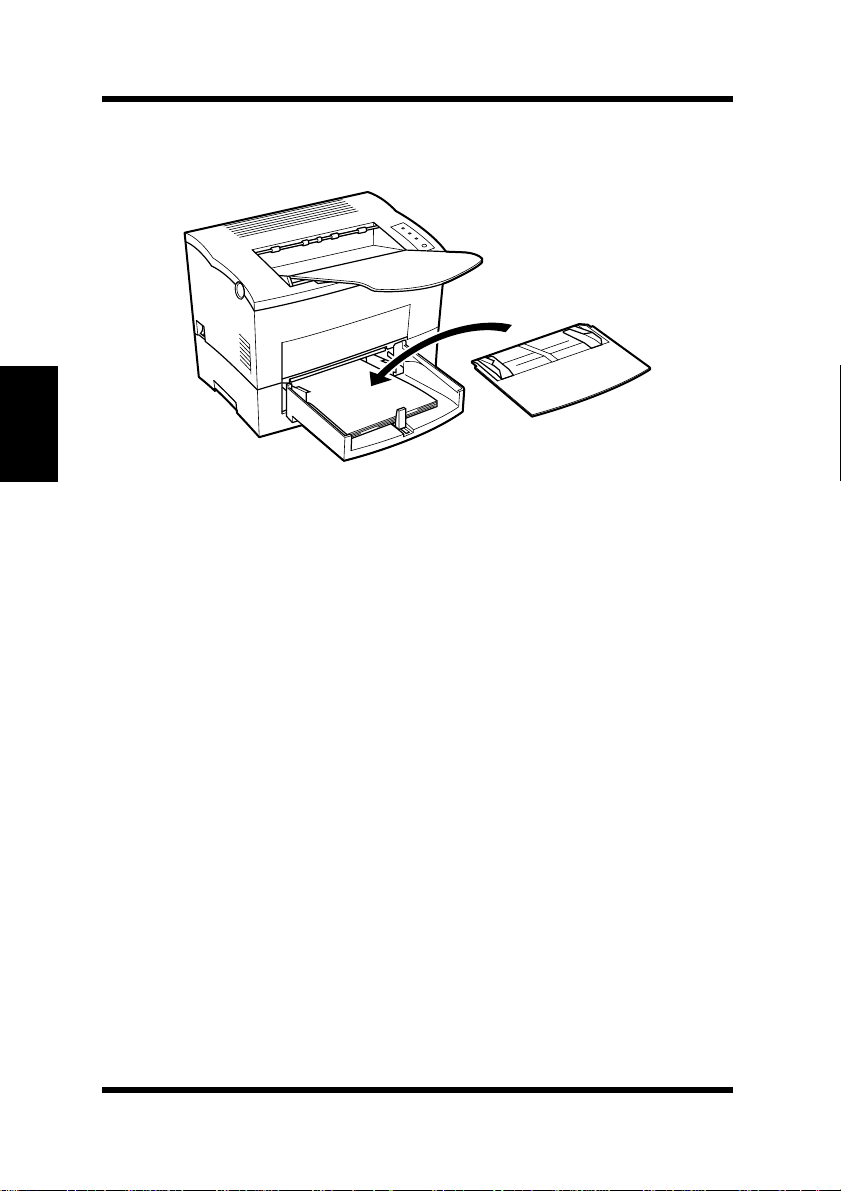
Chapter 3
Replace the tray cover onto Tray 1.
4
Using the Printer
3-6
Page 75
Loading Paper
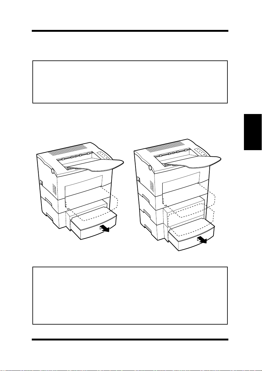
Loading Paper onto Tray 2/Tray 3
Note
• Make sure that the
to be used for printing has been installed into the
cassette unit
T r ay 3 cassette
refer to Chapter 2.
Slide Tray 2/Tray 3 out of the second/third paper cassette unit
1
Tray 2/Tray 3 cassette
. For instructions on inserting (and removing) the
into (and from) the
as illustrated.
Tray 2 Tray 3
for the proper size of paper
second/third paper
second/third paper cassette unit
Tray 2/
,
Chapter 3
Note
• The cassette is designed to remain in the unit during the normal loading
and operation of the printer. To remove
pull it out as far as it will go without force. Then gently raise the forward-end up, and remove
•
Tray 2
Minolta Technical Support to find out how you can acquire this tray to
increase the capabilities of your printer.
and
Tray 3
Tray 2/Tray 3
are available as an option for this printer. Contact
Tray 2/Tray 3
from the unit.
from the unit,
Using the Printer
3-7
Page 76
Loading Paper
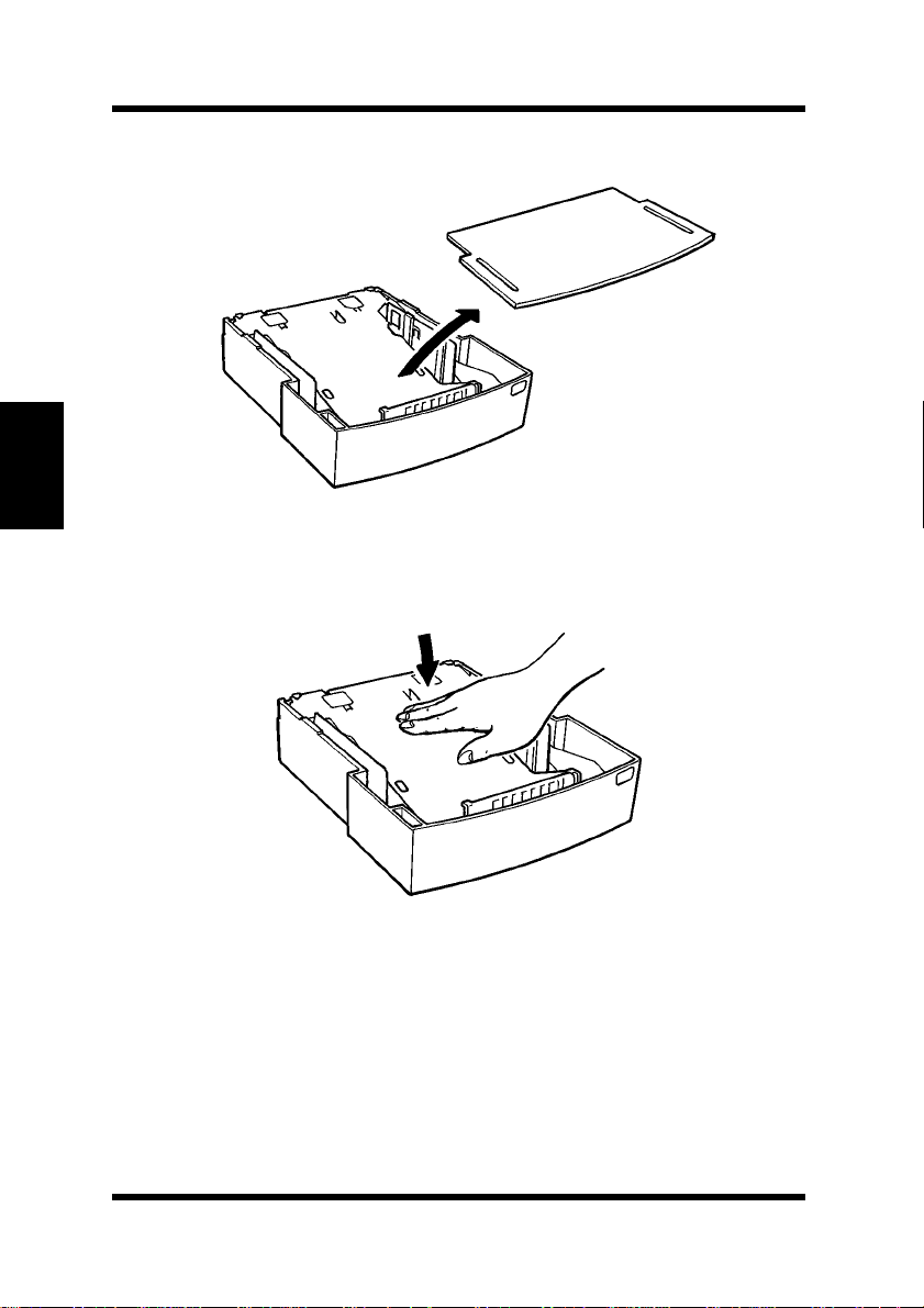
Chapter 3
Remove the cassette cover from Tray 2/Tray 3.
2
Press down on the paper lifting plate located inside of Tray 2/
3
Tray 3 until it locks.
Using the Printer
3-8
Page 77
Loading Paper
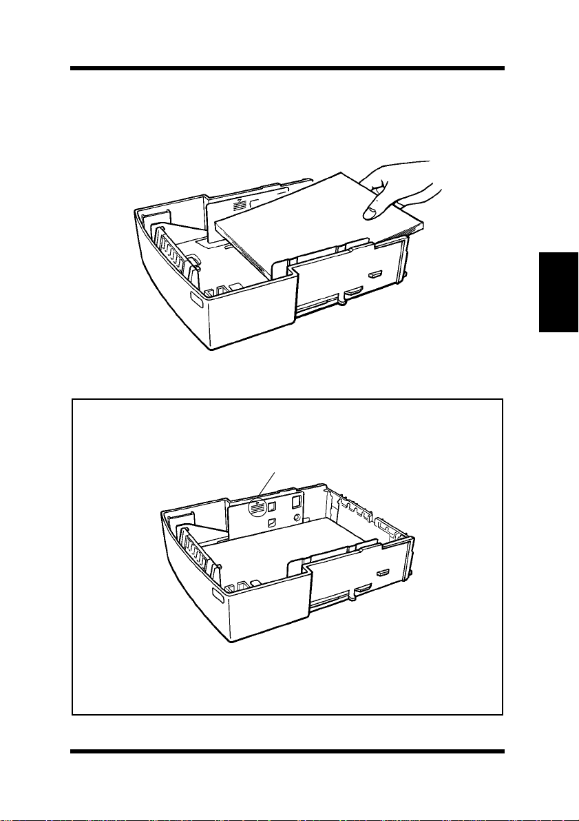
Place a stack of up to 500 sheets of paper into Tray 2/Tray 3 so
4
that the side that was facing up when the paper was unwrapped is
still facing up.
Note
• A maximum level mark inside the inlet of
high you can stack paper. Make sure that paper is stacked no higher
than this mark.
Maximum level mark
Tray 2/Tray 3
shows how
Chapter 3
Using the Printer
•
Tray 2/Tray 3
• Do not load additional paper until all the paper currently on
is completely used up.
Tray 3
does not support landscape-oriented paper-feeding.
Tray 2/
3-9
Page 78
Loading Paper
Chapter 3
Replace the cassette cover and insert Tray 2/Tray 3 into the
5
second/third paper cassette unit.
Tray 2
Tray 3
Using the Printer
3-10
Page 79
Loading Paper
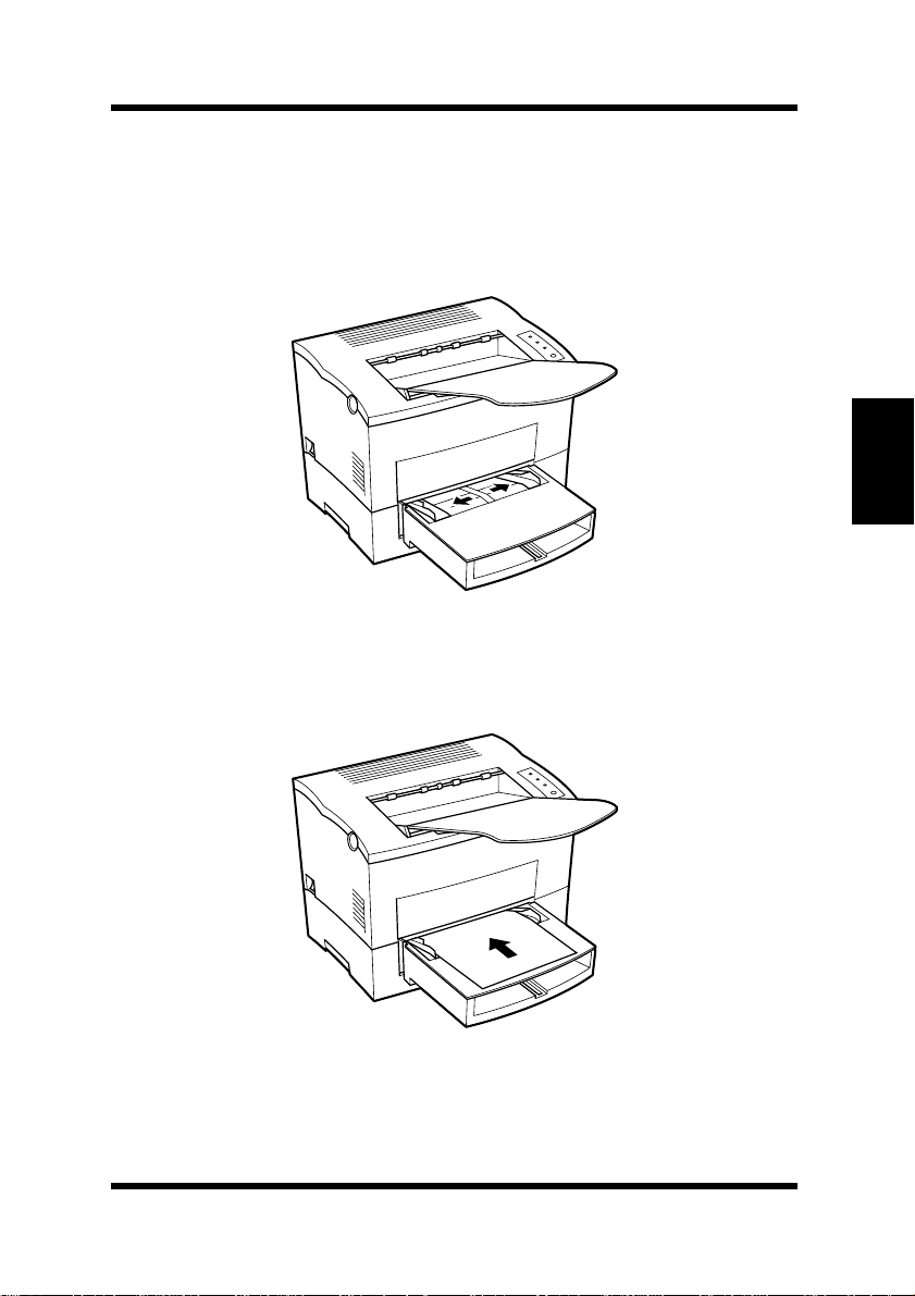
Manual Paper Feed
Make sure that the tray cover is properly attached to Tray 1.
1
Open the paper size guides.
2
Insert the sheet of paper into the manual feed tray with the side
3
to be printed facing up.
Chapter 3
Using the Printer
3-11
Page 80
Loading Paper
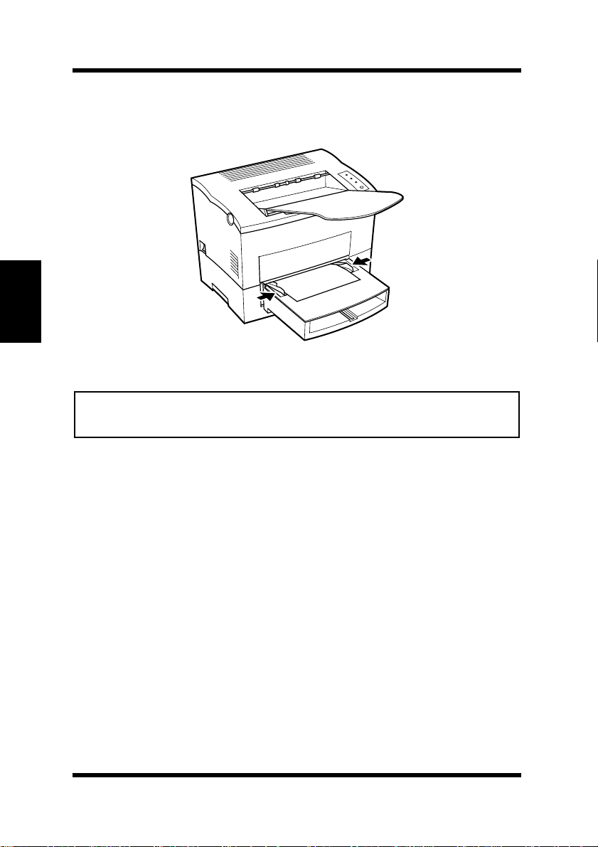
Chapter 3
Adjust the paper size guides so that both sides of the paper are
4
secure.
Note
• Insert only one sheet of paper or one envelope at a time when feeding
manually.
Using the Printer
3-12
Page 81
Loading Paper
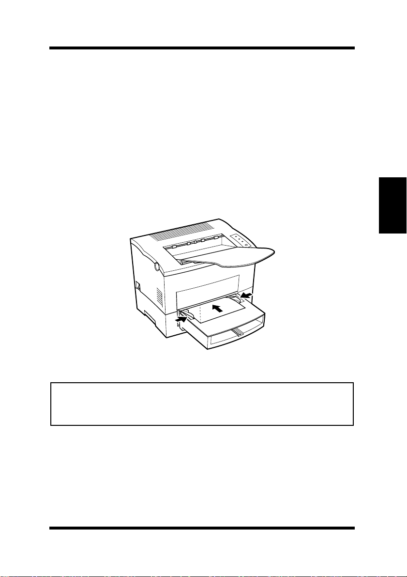
Printing on Envelopes
The manual feed tray supports feeds of Commercial 10, Monarch,
DL, C5, and B5 envelopes.
Manually feed envelopes one by one into the manual feed tray.
Place the envelope with the side to be printed facing up on the
1
tray. The flap of the envelope should be facing down and to the
left.
Make sure that the env elope is placed in the center of the tray and
2
that it is secured by the paper size guides.
Chapter 3
Note
• Because there is great variation in the quality of paper used for envelopes, we suggest that you produce test prints of various types before
purchasing any envelope in large quantities for use with this printer.
Note the following points whenever printing on envelopes.
• Make sure that all edges are creased sharply and that all flaps are
folded correctly.
Using the Printer
3-13
Page 82

Loading Paper
Chapter 3
• Do not use envelopes that are self-adhesive. Use only envelopes
that have standard sealing that sticks after it is moistened.
• Use envelopes of which flaps run the entire length of the envelope.
Envelopes that seal at one end will not feed properly.
• Do not use envelopes that have a window. Such envelopes can seriously damage the printer.
• Do not use envelopes that are wrinkled.
• Never use envelopes that have clasps or any other type of fastener
that can damage the printer.
• Do not store envelopes in an area that is subject to high humidity.
Using the Printer
3-14
Page 83
Loading Paper
Duplex Printing
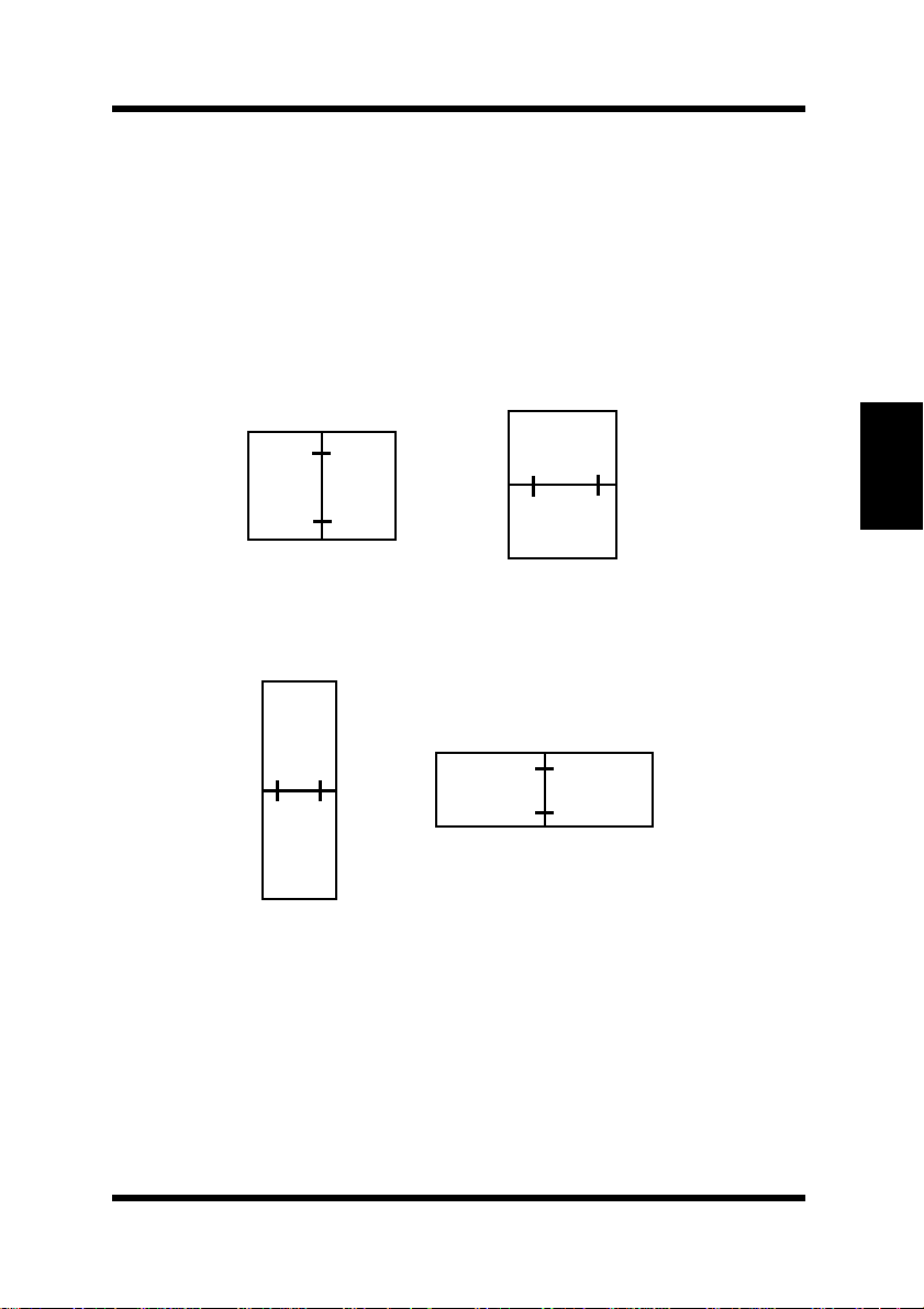
This feature prints document data on both sides of a sheet of paper.
Installation of the optional duplex unit is required to perform duplex
printing.
You can choose either Bind Long Edge or Bind Short Edge when
generating duplex documents.
(1) Bind Long Edge
A
A
A
A
Chapter 3
Portrait
(2) Bind Short Edge
A
A
Portrait
Landscape
A
Landscape
Using the Printer
A
3-15
Page 84

Loading Paper
The supported paper types and sizes for duplex printing are as follows.
Paper Type
Plain paper: 64 to 90 g/m2 (17 to 24 lb)
2
Recycled paper: 64 to 90 g/m
(17 to 24 lb)
Note
• Do not use special paper (transparencies, labels, envelopes, letterhead,
J-Post and thick paper) for duplex printing.
Paper Size
Chapter 3
A4, A5, JIS B5, Letter, Legal, Executive.
Note
• The Long Edge Binding setting of the printer driver cannot be used to
print duplex documents on custom size paper.
Remember the following points when generating duplex documents:
Using the Printer
• The size of both original documents that will be used to make one
duplex document must be the same.
• The original document that is loaded first into the duplex unit will
be output face down.
3-16
Page 85

Chapter
Printer Driver
Chapter 4
4
Printer Driver
Page 86

Chapter 4
Printer Driver
Page 87

Introduction
Introduction
This printer driver was especially designed to provide true Windowsbased and DOS printing for your Minolta printer. The dri v er consists of
three programs: the printer status display, the control panel and the
driver itself.
Important!
• This printer driver is located on the CD-ROM that comes with your
printer. If your computer does not ha v e a CD-ROM drive or you wish
to download the updated printer driv er , it can be do wnloaded from the
Minolta Web site at
http://www.minoltaprinters.com
.
System Requirements
The following describes the minimum system requirements for running
the Minolta PageWorks/Pro 18/18N printer driver.
Operating System: Microsoft Windows 95, Windows 98, Windows
3.1x, Windows NT 4.0 or MS-DOS
Chapter 4
Personal Computer: IBM-compatible PC with at least a 486DX
16MHz CPU (Pentium processor recommended)
CD-ROM drive
I/O Interface: IEEE 1284 type-B parallel cable
Memory: At least 8MB of PC RAM
Free Disk Space: Approximately 5MB for files
Note
• Use of a poor quality parallel cable may adversely affect input.
Printer Driver
4-1
Page 88

Installing the Printer Driver Under Windows 95/98
Installing the Printer Driver Under
Windows 95/98
This section provides information on installing the printer driver under
Windows 95/98. It also tells you how to uninstall the printer driver
when necessary.
W e recommend that the printer driver be installed using the CD-R OM’s
installer. If the driver is installed using plug-and-play, the
directory on the CD-ROM must be specified.
Note
• When the printer driver is installed using plug-and-play, the Status
Display, the Control Panel, the uninstall.exe file, and the Driver Help
will not be installed.
Driver
Chapter 4
To Install the Printer Driver Using the Installer
(Auto Run)
1
2
Printer Driver
3
4-2
Turn on your computer and start up Windows 95 or Windows 98.
Insert the
ROM drive.
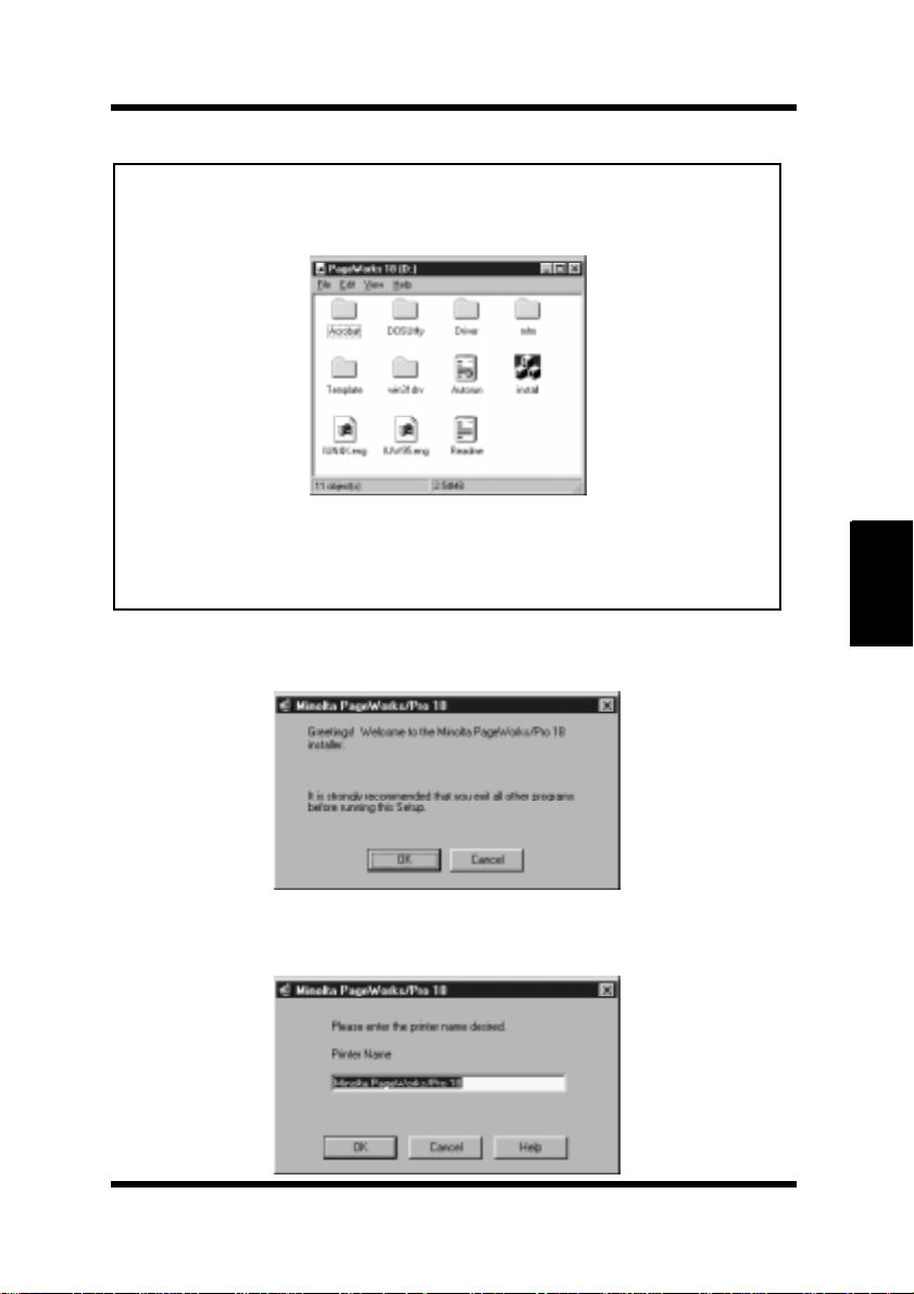
The opening screen is automatically displayed. Click on the
Driver
Printer Driver
menu to start the installer.
CD-ROM into your computer’s CD-
PCL
Page 89
Installing the Printer Driver Under Windows 95/98
Note
• The configuration of some computers may prevent the opening screen
from appearing automatically. If the screen does not appear, doubleclick
Install.exe
• The printer driver must be installed using the CD-R OM’ s installer. Do
not use the Add Printer wizard from the Printers folder. Installation
through the Add Printer wizard will prevent the printer from performing properly.
from the CD-ROM.
Follow the instructions that appear on your computer screen to
4
complete the installation.
When the following dialog appears, you can assign a name to the
5
printer. When the name is as you want it, click
OK
.
Chapter 4
Printer Driver
4-3
Page 90
Installing the Printer Driver Under Windows 95/98
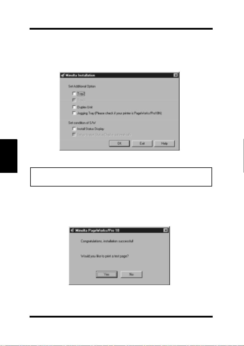
When the following dialog appears, check the option(s) that are
6
installed onto your printer. If you want to install the status display, check the “Install Status Display” box. Then click
display the next step.
OK to
Chapter 4
Note
• This printer does not support jogging tray compatibility. Do not
7
Printer Driver
4-4
check Jogging Tray in this dialog.
After the installation is completed, the following dialog appears.
Printing a test page is recommended to confirm that the printer
driver is correctly installed on your computer.
Page 91
Installing the Printer Driver Under Windows 95/98
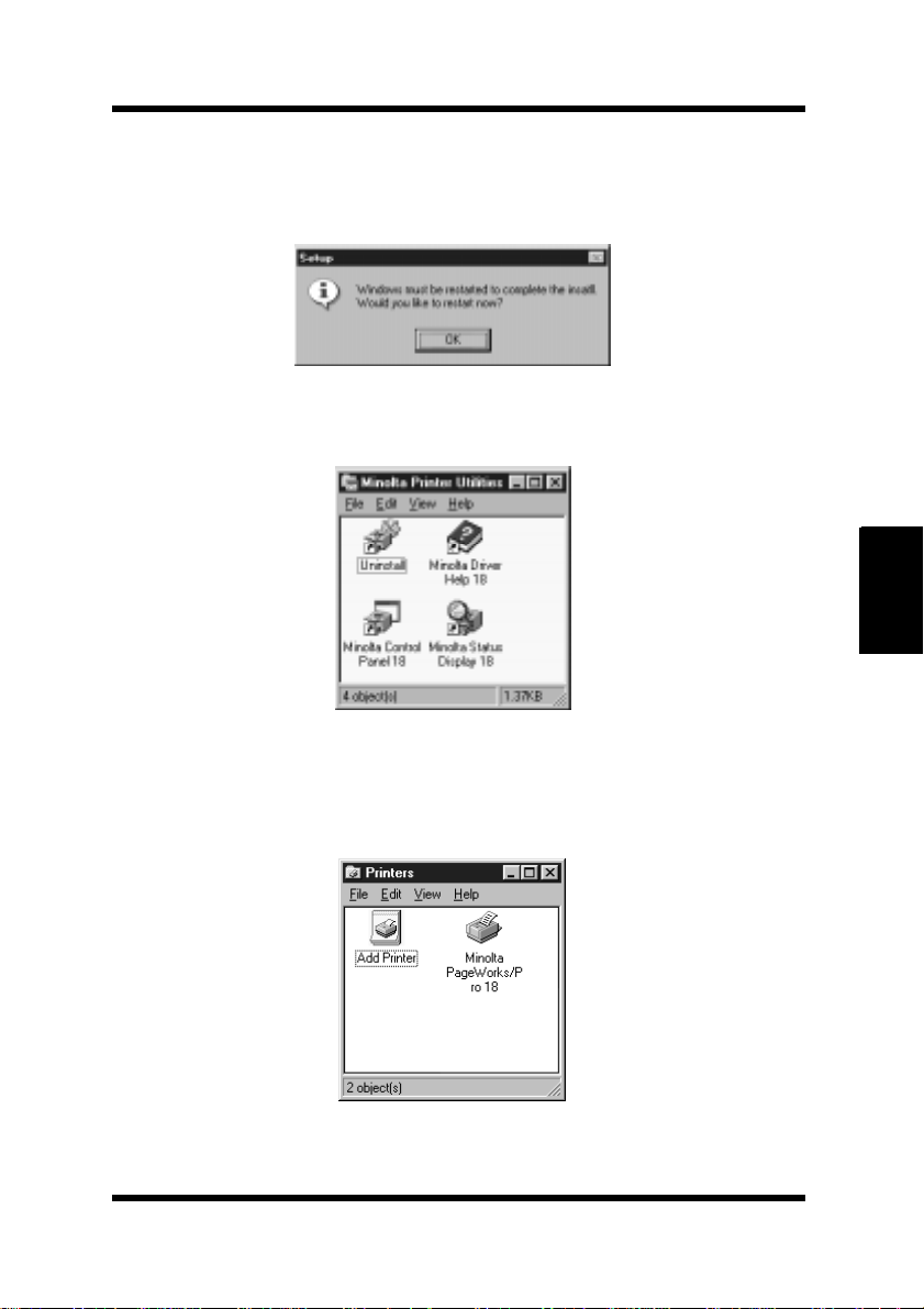
A message suggesting that you restart the computer will appear.
8
Close any applications that are currently active on your desktop
and click
The following dialog appears on the desktop of the computer.
9
OK to restart the computer.
Chapter 4
Make sure that the Minolta PageWorks/Pro 18 printer icon is
10
displayed in the Printers dialog. Click
and then click
This completes the installation of the printer driver.
Printers to display the Printers dialog.
Start, point to Settings,
Printer Driver
4-5
Page 92
Installing the Printer Driver Under Windows 95/98
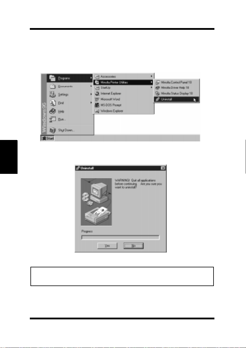
To Uninstall the Printer Driver
1
2
Chapter 4
Printer Driver
Click the
ties
Click
Start
, and then click
Yes
button, point to
Uninstall.
to proceed with the uninstall operation or No to abort.
Programs, Minolta Printer Utili-
Note
• This uninstall operation will delete all of the printer driver(s) that are
currently installed in the Minolta Printer Utilities group.
4-6
Page 93
Installing the Printer Driver Under Windows 95/98
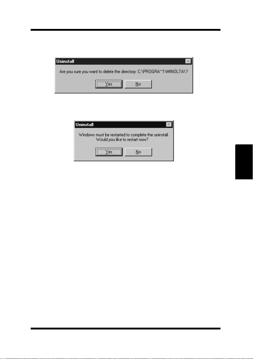
Click Yes to delete the directory that contains the Minolta Printer
3
Utilities program.
In the next dialog that appears, click Yes to restart the computer.
4
Chapter 4
4-7
Printer Driver
Page 94
Installing the Printer Driver Under Windows NT 4.0
Installing the Printer Driver Under
Windows NT 4.0
This section provides information on installing the printer driver on a
computer running Windows NT 4.0. It also tells you how to uninstall
the printer driver when necessary.
To Install the Printer Driver Using the Installer
(Auto Run)
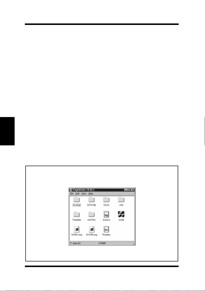
Turn on your computer and start up Windows NT 4.0.
1
2
• In this example, we will assume that
Chapter 4
3
Note
• The configuration of some computers may prevent the opening screen
Printer Driver
• The printer driver must be installed using the CD-ROM’s installer. Do
Insert the
ROM drive.
ROM drive.
The opening screen is automatically displayed. Click on the
Driver
from appearing automatically. If the screen does not appear, doubleclick
not use the Add Printer wizard from the Printers folder.
Printer Driver
menu to start the installer.
Install.exe
from the CD-ROM.
CD-ROM into your computer’s CD-
D:
is the name of the CD-
PCL
4-8
Page 95
Installing the Printer Driver Under Windows NT 4.0
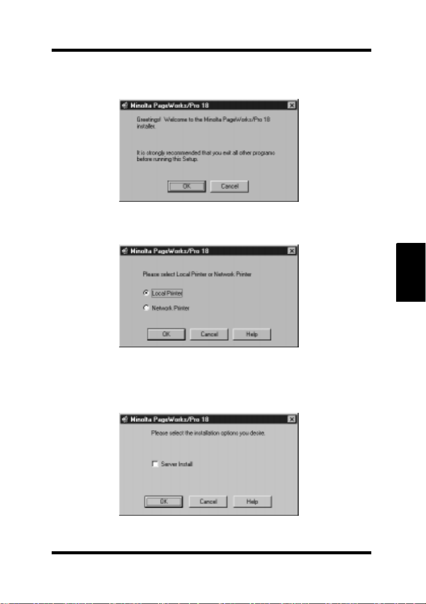
Follow the instructions that appear on your computer screen to
4
complete the installation.
Select Local Printer.
5
Chapter 4
Click the OK button to display the next dialog.
6
Select the installation options.
7
Printer Driver
4-9
Page 96
Installing the Printer Driver Under Windows NT 4.0
Chapter 4
If the computer onto which you are installing the driver is a print
8
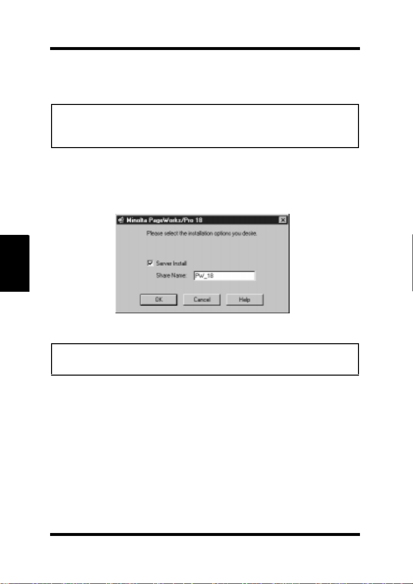
server, check the
Server Install checkbox.
Note
• If your printer is connected to a Network, we recommend consulting
your network administrator and referring to the Network Interface Card
Manual.
If you plan to use the printer as a network printer, type in a name
9
for
Share Name.
Example: PW_18
Note
Printer Driver
• Skip step 9 if you did not check the
10
4-10
Server Install
above.
Click OK to display the next dialog.
option in step 8
Page 97
Installing the Printer Driver Under Windows NT 4.0
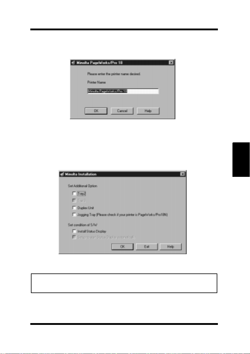
When the following dialog appears, you can assign a name to the
11
printer. When the name is as you want it, click
When the following dialog appears, check the option(s) that are
12
installed onto your printer. If you want to install the status display, check the “Install Status Display” box. Then click
display the next step.
OK.
OK to
Chapter 4
Note
• This printer does not support jogging tray compatibility. Do not
check Jogging Tray in this dialog.
Printer Driver
4-11
Page 98
Installing the Printer Driver Under Windows NT 4.0
13
14
Chapter 4
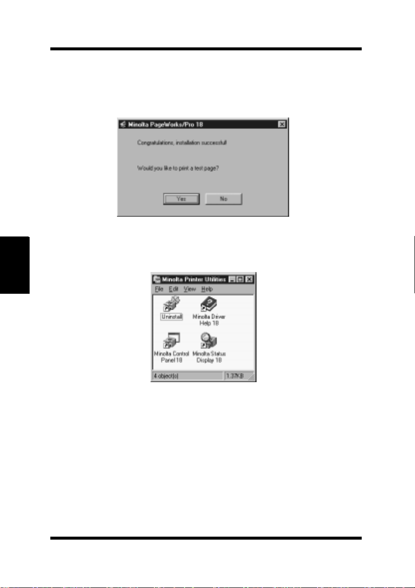
After the installation is completed, the following dialog appears.
Printing a test page is recommended to confirm that the printer
driver is correctly installed on your computer.
The following dialog appears on the desktop of the computer.
Printer Driver
15
4-12
In the installer menu window, click Quit to close the window.
Page 99
Installing the Printer Driver Under Windows NT 4.0
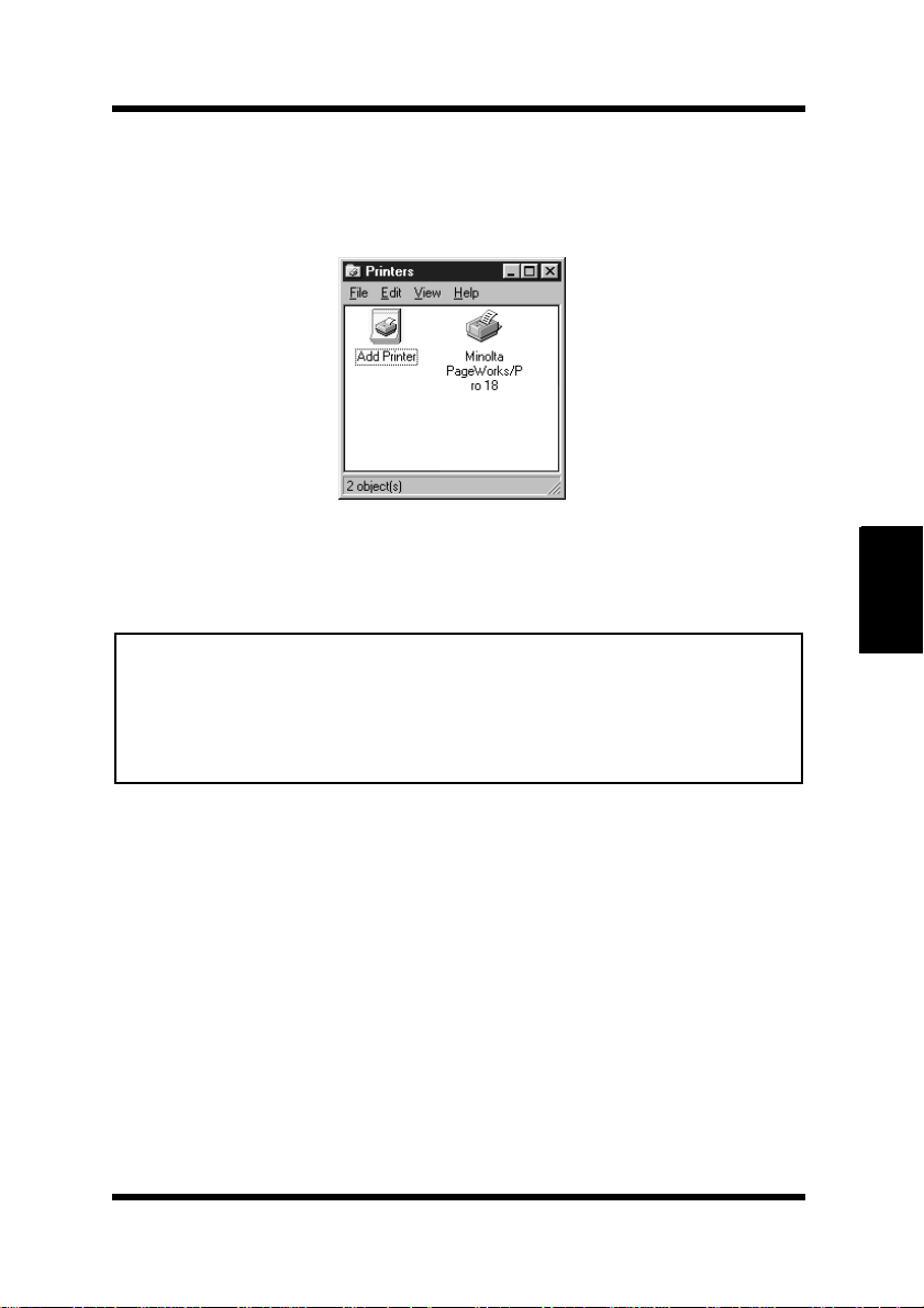
Make sure that the Minolta PageWorks/Pro 18 printer icon is
16
displayed in the Printers dialog. Click
and then click
Printers to display the Printers dialog.
This completes the installation of the printer driver.
Start, point to Settings,
Note
• The
• The printer driver must be installed using the CD-ROM’s installer. Do
Additional Options
designated as a
tion procedure.
not use the Add Printer wizard from the Printers folder.
“Network Printer”
dialog does not appear when the printer is
in the second dialog of the installa-
4-13
Chapter 4
Printer Driver
Page 100
Installing the Printer Driver Under Windows NT 4.0
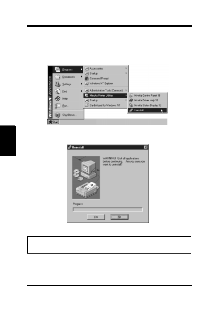
To Uninstall the Printer Driver
1
2
Chapter 4
Printer Driver
Click the
ties
Click
Start
, and then click
to proceed with the uninstall operation or No to abort.
Yes
button, point to
Uninstall
.
Programs, Minolta Printer Utili-
Note
• This uninstall operation will delete all of the printer driver(s) that are
currently installed in the Minolta Printer Utilities group.
4-14
 Loading...