

Page 1

Network Interface Card
NC-503
User’s Guide
Page 2

Introduction
Thank you for purchasing this machine.
This manual provides descriptions on the use of network printing and network scanning functions used with the Internet or on an intranet.
Be sure to read this manual before performing any operations.
For precautions concerning the use and safety of the machine, refer to the
User’s Guide provided with the machine.
Store the CD-ROM and User’s Guides provided with the machine in a safe
place.
bizhub 163/211 is not sold in the USA market.
Trademarks and copyright
- KONICA MINOLTA, the KONICA MINOLTA logo, and The essentials of
imaging are registered trademarks of KONICA MINOLTA HOLDINGS,
INC.
- PageScope and bizhub are registered trademarks or trademarks of
KONICA MINOLTA BUSINESS TECHNOLOGIES INC.
- Netscape is a registered trademark of Netscape Communications Corpo-
ration in the United States and other countries.
- Novell and Novell NetWare are registered trademarks of Novell, Inc. in the
United States and other countries.
- Microsoft, Windows, and Windows NT are either registered trademarks
or trademarks of Microsoft Corporation in the United States and/or other
countries.
- Adobe, the Adobe logo, Acrobat and PostScript are either registered
trademarks or trademarks of Adobe Systems Incorporated in the United
States and/or other countries.
- Ethernet is a registered trademark of Xerox Corporation.
- PCL is a registered trademark of Hewlett-Packard Company Limited.
- All other product and brand names are trademarks or registered trade-
marks of their respective companies or organizations.
About PageScope Web Connection
Network utility PageScope Web Connection can be used when a network interface card is installed. PageScope Web Connection is an extremely useful
network utility for specifying network and other settings over the network.
PageScope Web Connection can be used simply with the Web browser (Internet Explorer or Netscape Navigator) installed on the computer; no special
software is required. For details on using PageScope Web Connection, refer
to “Using PageScope Web Connection” on page 8-1.
NC-503 x-1
Page 3

Copyright
© 2007 Konica Minolta Business Technologies, Inc. All Rights Reserved.
Note
- This User’s Guide may not be reproduced in part or in full without permis-
sion.
- Konica Minolta Business Technologies, Inc. will not be held liable for any
incidents caused by using this User’s Guide.
- Information included in this User’s Guide is subject to change without no-
tice.
- Views of the actual equipment may be slightly different from the illustra-
tions used in this User’s Guide.
x-2 NC-503
Page 4

Contents
Introduction
About PageScope Web Connection ...............................................x-1
Copyright ........................................................................................x-2
Contents ............................................................................................ x-3
Explanation of manual conventions ................................................ x-9
1 Getting ready
1.1 Overview ............................................................................................ 1-1
1.2 Names of control panel parts and their functions ......................... 1-2
1.3 Entering text ...................................................................................... 1-7
Changing the input mode .............................................................. 1-7
Key operation ................................................................................. 1-7
Text input example ......................................................................... 1-8
Correcting text and input precautions ......................................... 1-11
1.4 Connecting to a local area network (LAN) ................................... 1-12
Connecting the network cable ..................................................... 1-12
Network port LEDs ....................................................................... 1-12
2 Network printing
2.1 Selecting the network printing method .......................................... 2-1
When using a Windows operating system ..................................... 2-1
When using a NetWare environment
(NetWare server and Windows client) ............................................ 2-4
2.2 Checking the setup .......................................................................... 2-5
Peer-to-peer printing ...................................................................... 2-5
LPR/PORT9100 printing ................................................................. 2-6
IPP printing ..................................................................................... 2-7
NetWare server/client (except NDPS) ............................................ 2-8
NetWare server/client (NDPS) ........................................................ 2-8
2.3 Specifying an IP address ................................................................. 2-9
2.4 Printing the settings information ................................................... 2-13
2.5 Connecting the computer and this machine over a network ..... 2-15
Peer-to-peer printing .................................................................... 2-15
LPR printing ................................................................................. 2-16
PORT9100 printing ....................................................................... 2-17
IPP printing ................................................................................... 2-18
Checking IPP-related settings from PageScope
Web Connection .......................................................................... 2-19
NC-503 x-3
Page 5

IPP printing connections ...............................................................2-20
Connecting the IPP printing NetWare server and this machine ...2-21
3 Network scanning
Scan to E-mail ................................................................................3-2
Scan to Server (FTP) .......................................................................3-3
Environments for network scan transmissions ...............................3-4
4 Network settings
4.1 Network settings ...............................................................................4-1
List of network settings ...................................................................4-1
4.2 Specifying settings from the control panel .....................................4-6
4.3 NETWORK SETTING .........................................................................4-7
Specifying the IP address, subnet mask and default gateway .......4-7
Specifying the DNS settings .........................................................4-11
Specifying the gateway transmission setting ...............................4-13
Specifying the WEB setting ..........................................................4-14
Specifying the LPD setting ...........................................................4-15
Specifying the SLP setting ............................................................4-16
Specifying the SNMP setting ........................................................4-17
4.4 E-MAIL SETTING 1 ..........................................................................4-18
Programming the sender’s name .................................................4-18
Specifying the e-mail address of the sender ................................4-21
Specifying the SMTP server address ............................................4-22
Specifying the SMTP port number ...............................................4-23
Specifying the SMTP server connection timeout .........................4-23
Specifying the text input setting ...................................................4-24
Specifying the subject of e-mail messages ..................................4-25
Specifying the POP before SMTP setting .....................................4-26
4.5 E-MAIL SETTING 2 ..........................................................................4-27
Specifying the POP3 server address ............................................4-27
Specifying the POP3 port number ................................................4-29
Specifying the POP3 server connection timeout ..........................4-30
Specifying the POP3 account .......................................................4-31
Specifying the POP3 password ....................................................4-32
4.6 USER SETTING ................................................................................4-33
Specifying the NTP server ............................................................4-33
Specifying the time zone ..............................................................4-35
x-4 NC-503
Page 6

5 Registering destinations
5.1 Registering destinations .................................................................. 5-1
Registering one-touch dial destinations ........................................ 5-2
Registering speed dial destinations ............................................... 5-4
Registering speed dial destinations (FTP servers) ......................... 5-7
Registering group dial destinations ............................................... 5-7
5.2 Editing or deleting registered information ................................... 5-11
Editing or deleting a one-touch dial destination .......................... 5-11
Editing or deleting a speed dial destination ................................. 5-14
Editing or deleting a group dial destination ................................. 5-16
6 Performing a Scan to E-mail operation
6.1 Basic transmission ........................................................................... 6-1
Using the automatic document feeder .......................................... 6-1
Positioning documents on the original glass ................................. 6-3
6.2 Changing the transmission settings ............................................. 6-10
Specifying the subject .................................................................. 6-10
Specifying a cc address ............................................................... 6-11
Selecting the file format ............................................................... 6-15
Selecting the compression encoding method ............................. 6-17
6.3 Changing the scanning quality settings ....................................... 6-19
Selecting the resolution ............................................................... 6-19
Selecting the document quality ................................................... 6-21
6.4 Changing the document scanning density ................................... 6-23
When “TEXT/PHOTO” or “TEXT” was selected ........................... 6-23
When “PHOTO” was selected ..................................................... 6-26
6.5 Specifying the default scanning settings ..................................... 6-28
Selecting the resolution ............................................................... 6-28
Selecting the file format ............................................................... 6-29
Selecting the compression encoding method ............................. 6-30
6.6 If the memory becomes full while scanning documents ............ 6-31
6.7 Specifying a one-touch dial destination ....................................... 6-33
6.8 Specifying a speed dial destination .............................................. 6-35
6.9 Specifying a recipient from a group dial destination .................. 6-37
6.10 Selecting a destination from the phone book .............................. 6-39
Searching the phone book ........................................................... 6-41
6.11 Checking the communication results ........................................... 6-44
NC-503 x-5
Page 7

7 Performing a Scan to Server (FTP) operation
7.1 Basic transmission ............................................................................7-1
Using the automatic document feeder ...........................................7-1
Positioning documents on the original glass ..................................7-5
7.2 If the memory becomes full while scanning documents .............7-11
8 Using PageScope Web Connection
8.1 When using PageScope Web Connection .......................................8-1
8.2 About PageScope Web Connection ................................................8-1
8.3 System requirements ........................................................................8-3
8.4 Accessing PageScope Web Connection .........................................8-4
8.5 Structure of pages .............................................................................8-5
Description of the pages .................................................................8-5
Operation ........................................................................................8-6
Web browser cache ........................................................................8-6
With Internet Explorer: ....................................................................8-7
With Netscape Navigator: ...............................................................8-7
8.6 Logging on to Administrator mode ..................................................8-8
To log on to Administrator mode ....................................................8-8
8.7 User mode ........................................................................................8-10
User mode tabs ............................................................................8-10
System tab — Summary ...............................................................8-11
System tab — Details — Input Tray .............................................8-12
System tab — Details — Output Tray ...........................................8-13
System tab — Details — ROM Version ........................................8-14
System tab — Details — Interface Information ............................8-15
System tab — Details — Consumable .........................................8-16
System tab — Maintenance — Counter .......................................8-17
System tab — Online Assistance .................................................8-18
Job tab — Print Job Management ................................................8-19
Job tab — File Download .............................................................8-20
Print tab — Settings — Paper Handling .......................................8-21
Print tab — Settings — Page Layout ............................................8-22
Print tab — Settings — Printer Setting .........................................8-23
Print tab — Test Print ...................................................................8-24
Print tab — Font Information ........................................................8-25
Scan tab — One-Touch Dial Setting ............................................8-26
Scan tab — Speed Dial Setting ....................................................8-27
Scan tab — Group Dial Setting ....................................................8-28
Network tab — Summary .............................................................8-29
x-6 NC-503
Page 8

8.8 Administrator mode ........................................................................ 8-30
Administrator mode tabs ............................................................. 8-30
System tab — Summary .............................................................. 8-31
System tab — Details .................................................................. 8-32
System tab — Preference ............................................................ 8-33
System tab — Save Setting ......................................................... 8-34
System tab — Maintenance — NIC and
Printer Controller Reset ................................................................ 8-36
System tab — Maintenance — Initialize ...................................... 8-37
System tab — Maintenance — Counter ...................................... 8-38
System tab — Online Assistance ................................................. 8-39
Job tab — Print Job Management ............................................... 8-40
Print tab — Settings — Paper Handling ...................................... 8-41
Print tab — Settings — Page Layout ........................................... 8-42
Print tab — Settings — Printer Setting ........................................ 8-43
Print tab — Test Print ................................................................... 8-44
Print tab — Font Information ....................................................... 8-45
Scan tab — One-Touch Dial Setting ............................................ 8-46
Sample page: For a fax destination ............................................. 8-48
When “Fax” is selected: ............................................................... 8-48
When “E-Mail” is selected: .......................................................... 8-49
When “Group Dial” is selected: .................................................... 8-49
Scan tab — Speed Dial Setting ................................................... 8-50
Sample page: For an e-mail destination ...................................... 8-52
When “Fax” is selected: ............................................................... 8-52
When “E-Mail” is selected: .......................................................... 8-53
When “FTP Server Address” is selected: ..................................... 8-54
Scan tab — Group Dial Setting .................................................... 8-55
Scan tab — Fax Configuration ..................................................... 8-58
Scan tab — Downloading/Uploading Destination List ................. 8-60
Upload .......................................................................................... 8-61
Network tab — Summary ............................................................. 8-61
Network tab — TCP/IP Configuration .......................................... 8-62
Network tab — NetWare Configuration — NetWare Setting ....... 8-63
Network tab — NetWare Configuration — NetWare Status ........ 8-65
Network tab — IPP Configuration ................................................ 8-66
Network tab — SMTP & POP3 Configuration .............................. 8-68
Network tab — FTP & DNS Configuration ................................... 8-70
NC-503 x-7
Page 9

9 Troubleshooting
9.1 Main error messages and their remedies .......................................9-1
9.2 Troubleshooting ................................................................................9-2
Network printing .............................................................................9-2
Scan to E-mail ................................................................................9-2
PageScope Web Connection .........................................................9-3
10 Appendix
10.1 Main product specifications ...........................................................10-1
Network printing ...........................................................................10-1
Scan to E-mail/Scan to Server (FTP) ............................................10-1
x-8 NC-503
Page 10

Explanation of manual conventions
NC-503 x-9
Page 11

x-10 NC-503
Page 12

Getting ready
1 Getting ready
This chapter provides information that is important to know before this device is used.
1.1 Overview
By installing the network interface card, this machine can be used as a network printer. In addition, since the machine is preprogrammed with scanning
functions, paper documents can easily be converted to electronic data and
used, for example, with electronic filing allowing easy access to the information. Scanned image data (scan data) can be saved as TIFF or PDF files and
sent to other computers through a network.
1
NC-503 1-1
Page 13

1
Getting ready
1.2 Names of control panel parts and their functions
1 2 3
4
5
6
21
20
19
1018 11121314151617
No. Part name Description
1 [Power Save] key Press to enter Power Save mode.
2 [Mixed Original] key/indicator Press to select the “Mixed Original” setting.
3 [Simplex/Duplex] key/indicator Press to select double-sided copying. Select
4 Display Displays the number of copies, zoom ratio, fax
5[+, [,], [*] and [)] keys
[OK] key
6 [Printer] key/indicator This indicator lights up while data is being
7 [Access] key Press when account track settings have been
8 [Speed Dial] key Press to register frequently used fax numbers
9 [Phone Book] key Press to display the information programmed
10 [Back] key Press to return to the previous screen.
11 “Caution” indicator This indicator lights up or flashes if an error
“1-SIDE->1-SIDE”, “1-SIDE->2-SIDE”, “2SIDE->1-SIDE” or “2-SIDE->2-SIDE”. If any
setting other than “1-SIDE->1-SIDE” is selected, the indicator lights up.
mode, setting menus and error messages.
Press the [+], [,], [*] and [)] keys to select
menu items in the display and change their
settings.
Press the [OK] key to apply the current setting.
printed from the computer and flashes while
data is being sent. For details, refer to the User’s Guide for the printer driver.
applied.
and addresses, and to recall them during
transmissions.
for one-touch dialing, group dialing and speed
dialing.
has occurred.
7
8
9
1-2 NC-503
Page 14

Getting ready
No. Part name Description
12 [Density] key Press to select the scanning density of copies
13 [Quality] key Press to select “TEXT”, “PHOTO” or “TEXT/
14 [Zoom] key Press to specify whether to enlarge or reduce
15 [Paper] key Press to select the paper drawer that is to be
16 [Function] key/indicator Press to specify settings for advanced copy
17 [Finishing] key/indicator Press to select a copy Finishing function.
18 [Combine Original] key/indicator Press to specify 2in1 or 4in1 copy settings.
19 [Confirm] key Press to view the counters or transmission re-
20 [Utility] key Press to specify settings in Utility mode.
21 [Mode Memory] key Press to register specified copy programs and
and fax documents.
PHOTO” as the document quality.
the image when copying.
used.
operations and useful fax transmission/reception functions, such as copying with a binding
margin added and sending/receiving confidential documents.
sults, or to print a transmission result report.
MACHINE SETTING, PAPER SOURCE SETUP, CUSTOM SIZE MEMORY, USER MANAGEMENT, ADMIN. MANAGEMENT, COPY
SETTING 1, COPY SETTING 2, DIAL REGISTRATION, FAX REGISTRATION, FAX TX OPERATION, FAX RX OPERATION,
REPORTING, SCAN SETTING
recall them.
1
NC-503 1-3
Page 15

1
Getting ready
22 23 24 2625
27
28
30
No. Part name Description
22 [Fax] key/indicator Press to enter Fax mode. The indicator on the
23 [Scan] key/indicator Press to enter Scan mode. The indicator on
24 [Copy] key/indicator Press to enter Copy mode. The indicator on
25 [123/ABC] key Press to switch between number input mode
26 [Reset] key • Press to cancel all settings.
27 [Interrupt] key/indicator Press to enter Interrupt mode. The indicator
29
key lights up in green to indicate that the machine is in Fax mode.
the key lights up in green to indicate that the
machine is in Scan mode. (Available only
when network interface card NC-503 and image controller IC-206 are installed)
the key lights up in green to indicate that the
machine is in Copy mode.
and letter input mode.
• The currently specified job is canceled.
(Pressing this key does not switch the machine to Copy or Fax mode.)
on the key lights up in green to indicate that
the machine is in Interrupt mode.
Press the key again to cancel Interrupt mode
and return to the mode before Interrupt mode
was entered.
If this key is pressed while a received fax or
computer document is being printed, printing
stops so that the interrupting copy job can be
performed. Press this key again to continue
printing the received fax or computer document.
1-4 NC-503
Page 16

Getting ready
No. Part name Description
28 [Clear/Stop] key • Press to clear the entered number.
29 [Start] key/indicator • Press to start a copy operation.
30 Keypad • Use to type in the number of copies to be
• Press to stop a continuous copy operation.
• Press to stop the transmission/reception of
the fax.
• Press to stop the print job from the computer.
• Press to start sending a fax.
• Press to start a scanning operation (with
push scanning).
• If this key is pressed while this machine is
warming up, the next copy job is queued.
• The key lights up in green to indicate that
jobs can be queued, and the key lights up
in orange to indicate that the machine is not
ready to begin copy operations.
produced.
• Use to type in the various settings.
• Use to specify the fax/scan destination.
• Used to type in speed dial numbers and
text.
• In Fax mode, the key is used for tone
transmissions (pulse dialing), and the # key
is used for accessing an outside line.
1
NC-503 1-5
Page 17

1
Getting ready
31 32 33 34
35
36
No. Part name Description
31 Auto RX indicator This indicator lights up when the automatic re-
32 [Memory TX] key/indicator Press this key to select the memory transmis-
33 [On Hook] key Press to answer the call. Press this key again
34 [Redial/Pause] key Press to redial the last recipient called.
35 One-touch dial keys Used to dial previously registered fax num-
36 Switching plate Switches the numbers assigned to the one-
ception function is selected.
sion function. This indicator lights up in green
when the memory transmission function is selected.
to hang up.
While dialing, this key is used to generate a
pause when transferring from an internal to an
external line or receiving information services.
bers.
Use keys [01] through [32] for specifying onetouch dialing and group dialing settings. Use
keys [29] through [32] for specifying program
dialing settings.
touch dial keys. When the switching plate is in
the lower position, the keys are numbered [01]
through [16]. When the switching plate is in the
upper position, the keys are numbered [17]
through [32].
1-6 NC-503
Page 18

Getting ready
1.3 Entering text
Follow the procedure described below to enter text when specifying the user
name or programming one-touch dial keys with the recipient name.
Changing the input mode
Each press of the [123/ABC] key switches between number input mode and
letter input mode.
[1…]: Numbers can be entered.
[A…]: Letters and symbols can be entered.
Key operation
Using the keypad, type in numbers, letters and symbols.
Switch between numbers and letter/symbols by pressing the [123/ABC] key.
When [1…] appears in the display, numbers will be entered.
When [A…] appears in the display, letters/symbols will be entered.
“→” is treated as a tilde (
The following characters can be entered by each key in the keypad.
Characters that can be entered with keypad keys
1
~
).
2
Note
Repeatedly press the keypad key to scroll through the corresponding
characters and symbols listed until the desired character appears in the
display.
Keypad key Available characters
[1…] [A…]
1 1 . (period) @ _ (underscore) - (hyphen) 1
22A B C 2 a b c
33D E F 3 d e f
4 4 G H I 4 g h i
5 5 J K L 5 j k l
6 6 M N O 6 m n o
7 7 P Q R S 7 p q r s
8 8 T U V 8 t u v
9 9 W X Y Z 9 w x y z
NC-503 1-7
Page 19

1
Getting ready
Keypad key Available characters
[1…] [A…]
0 0 (space) 0
* + & / * = ! ? ( ) %
###
[ ] ^ ‘ ’ { } | ~ $ , : ; < > “
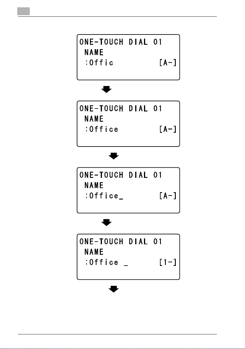
Text input example
To enter the name “Office 01”:
Press the [123/ABC] key until input mode [A…] is selected.
* The cursor (_) flashes alternately in the display with the character at its current location.
Press the [6] key 3 times.
1-8 NC-503
Page 20

Getting ready
1
Press the [3] key 7 times.
Press the [)] key.
Press the [3] key 7 times.
Press the [4] key 7 times.
Press the [2] key 7 times.
NC-503 1-9
Page 21
1
Getting ready
Press the [3] key 6 times.
Press the [0] key.
Press the [123/ABC] key.
Press the [0] key.
1-10 NC-503
Page 22

Getting ready
Correcting text and input precautions
To delete a part of the entered text:
Press the [*] or [)] key to move the cursor (_) below the character to be de-
leted, and then press the [Clear/Stop] key.
To change entered characters:
Press the [*] or [)] key to move the cursor (_) below the character that you
wish to change, and then enter the new character. The entered character is
inserted at the cursor’s position.
Entering text with the keypad keys:
To enter a character with the same key used to enter the previously entered
character, press the [)] key before entering the next character. (Refer to the
example on the previous page.)
To enter a space:
Press the [0] key in the keypad.
To stop entering text:
Press the [Reset] key.
1
Press the [1] key.
NC-503 1-11
Page 23

1
1.4 Connecting to a local area network (LAN)
This machine can transmit with the TCP/IP protocol on a LAN. Therefore, this
machine must be connected to the LAN with a network cable.
Connecting the network cable
Insert one plug on the network cable into the network port (LAN) on the left
side of the machine, and then insert the other plug into an available port on
the network hub.
LED1
LED2
Getting ready
2
Reminder
The network cable is not included with this machine; therefore, use Category 5 or 5e cable for the network cable.
Network port LEDs
LED1 (LINK): This indicator lights up when the network cable is correctly connected. If this indicator does not light up, even if it is assumed that the cable
is correctly connected, check the connection again. If this indicator still does
not light up, even though both ends are correctly connected, the network cable may damaged.
LED2 (ACT): This indicator flashes while data is being sent or received.
1-12 NC-503
Page 24

Network printing
2 Network printing
This chapter provides descriptions of the procedures for installing the network interface card and using this machine as a network printer.
2.1 Selecting the network printing method
When the network interface card is installed, various network printing methods are possible. The following procedure describes how to connect a computer to this machine over a network. Select an available network printing
method according to the operating system being used.
When using a Windows operating system
Peer-to-peer printing
Compatible operating systems: Windows 98 SE / Windows Me
2
Network interface
card NC-503
TCP/IP protocol
Computer
Peer-to-peer printing
- Using the Peer-to-Peer Utility, the computer and this machine are con-
nected over a network. Since there is no differentiation between client
and server computers, this method is appropriate for network connections on a small-scale LAN. The Peer-to-Peer Utility is installed on the
computer when the printer driver is installed.
NC-503 2-1
Page 25

2
Network printing
LPR printing / PORT9100 printing
Compatible operating systems: Windows 2000 / Windows XP / Windows
Sever 2003
Network interface
card NC-503
TCP/IP (LPR/RAW)
protocol
Computer
LPR printing
- Using the LPR (line printer remote) print service, the computer and this
machine are connected over a network.
- The LPR print service is supported by the operating system as the stand-
ard.
- Use a TCP/IP port, and use LPR as the print protocol.
PORT9100 printing
- Using the PORT9100 print service, the computer and this machine can
be connected over a network.
- The PORT9100 print service is supported by the operating system as the
standard.
- Use a TCP/IP port, and use RAW as the print protocol.
2-2 NC-503
Page 26

Network printing
IPP printing
Compatible operating systems: Windows 2000 / Windows XP / Windows
Sever 2003
2
Network interface
card NC-503
Access Access
IPP printing
- Using the IPP (Internet printing protocol) print service, the computer and
this machine are connected over a network.
- The IPP print service is supported by the operating system as the stand-
ard.
- Communications are established with HTTP (Hyper Text Transfer Proto-
col), one of the TCP/IP protocols. In order to prevent unauthorized access in companies and organizations, a firewall must be installed.
However, HTTP is generally configured to allow access through the firewall. Therefore, with an IPP connection where communications are established using HTTP, printing from a computer is possible with a printer
outside of the firewall.
TCP/IP (HTTP) protocol
Internet
Access
Computer
NC-503 2-3
Page 27

2
Network printing
When using a NetWare environment (NetWare server and Windows client)
In a NetWare environment, the Windows computer is used as a NetWare client, and printing with this machine is possible through the NetWare server.
NetWare server
TCP/IP protocol or
IPX/SPX protocol
NetWare
client PC
(Windows
computer)
Connecting the NetWare server and this machine
When connecting the NetWare server and this machine over a network, the
following methods are supported.
NetWare version Protocol Emulation Service mode
NetWare 4.x IPX NDS / Bindery Pserver / Nprinter
NetWare 5.x / 6 IPX NDS / Bindery Pserver / Nprinter
TCP/IP NDPS (lpr)
2
Note
If the GDI printer driver is to be used in a NetWare environment, run the
repair program provided for the operating system by Microsoft. Access
the following URL, and then run the repair program.
http://support.microsoft.com/kb/884897
2-4 NC-503
Page 28

Network printing
2.2 Checking the setup
This section provides an overview of the setup procedure that is required for
each network printing method.
Peer-to-peer printing
1 Connect the network cable. (Refer to “Connecting to a local area net-
work (LAN)” on page 1-12.)
2 From the machine’s control panel, specify the IP address, subnet mask
and default gateway. (Refer to “Specifying an IP address” on page 2-9.)
3 Print the settings information, and then check the settings. (Refer to
“Printing the settings information” on page 2-13.)
– If optional fax kit FK-506 and image controller IC-206 are not in-
stalled, the settings information cannot be printed from the machine’s control panel.
4 Install the printer driver. The Peer-to-Peer Utility is installed when the
printer driver is installed.
– If the GDI driver is to be installed, refer to the User’s Guide for the
GDI printer controller, included with this machine. If the PCL driver
(optional) is to be installed, refer to the User’s Guide for image controller IC-206, included with the IC-206 option.
2
5 Add the network port to the computer. (Refer to “Connecting the com-
puter and this machine over a network” on page 2-15.)
2
Reminder
When installing the printer driver on an operating system other than Windows 98 SE or Windows Me, the Peer-to-Peer Utility is not installed.
NC-503 2-5
Page 29

2
Network printing
LPR/PORT9100 printing
1 Connect the network cable. (Refer to “Connecting to a local area net-
work (LAN)” on page 1-12.)
2 From the machine’s control panel, specify the IP address, subnet mask
and default gateway. (Refer to “Specifying an IP address” on page 2-9.)
3 Print the settings information, and then check the settings. (Refer to
“Printing the settings information” on page 2-13.)
– If optional fax kit FK-506 and image controller IC-206 are not in-
stalled, the settings information cannot be printed from the machine’s control panel.
4 Install the printer driver.
– If the GDI driver is to be installed, refer to the User’s Guide for the
GDI printer controller, included with this machine. If the PCL driver
(optional) is to be installed, refer to the User’s Guide for image controller IC-206, included with the IC-206 option.
5 Add the network port to the computer. (Refer to “Connecting the com-
puter and this machine over a network” on page 2-15.)
2-6 NC-503
Page 30

Network printing
IPP printing
1 Connect the network cable. (Refer to “Connecting to a local area net-
2 From the machine’s control panel, specify the IP address, subnet mask
3 Print the settings information, and then check the settings. (Refer to
4 Install the printer driver. Specify the network port when the driver is in-
2
work (LAN)” on page 1-12.)
and default gateway. (Refer to “Specifying an IP address” on page 2-9.)
“Printing the settings information” on page 2-13.)
– If optional fax kit FK-506 and image controller IC-206 are not in-
stalled, the settings information cannot be printed from the machine’s control panel.
stalled.
– If the GDI driver is to be installed, refer to the User’s Guide for the
GDI printer controller, included with this machine. If the PCL driver
(optional) is to be installed, refer to the User’s Guide for image controller IC-206, included with the IC-206 option. For details on specifying the network port, refer to “Connecting the computer and this
machine over a network” on page 2-15.
NC-503 2-7
Page 31

2
Network printing
NetWare server/client (except NDPS)
1 Connect the network cable. (Refer to “Connecting to a local area net-
work (LAN)” on page 1-12.)
2 Specify the necessary settings for connecting this machine to a Net-
Ware server. (Refer to “Connecting the computer and this machine
over a network” on page 2-15.)
3 Specify the necessary settings for printing through a NetWare server
from a NetWare client. (Refer to “Connecting the computer and this
machine over a network” on page 2-15.)
NetWare server/client (NDPS)
1 Connect the network cable. (Refer to “Connecting to a local area net-
work (LAN)” on page 1-12.)
2 From the machine’s control panel, specify the IP address, subnet mask
and default gateway. (Refer to “Specifying an IP address” on page 2-9.)
3 Print the settings information, and then check the settings. (Refer to
“Printing the settings information” on page 2-13.)
– If optional fax kit FK-506 and image controller IC-206 are not in-
stalled, the settings information cannot be printed from the machine’s control panel.
4 Specify the necessary settings for connecting this machine to a Net-
Ware server. (Refer to “Connecting the computer and this machine
over a network” on page 2-15.)
5 Specify the necessary settings for printing through a NetWare server
from a NetWare client. (Refer to “Connecting the computer and this
machine over a network” on page 2-15.)
2-8 NC-503
Page 32

Network printing
2.3 Specifying an IP address
The following procedure describes how to assign the IP address to the machine from the control panel.
2
Note
The IP address setting should be specified according to instructions from
the network administrator.
The IP address setting is specified in Utility mode by the administrator.
1 Press the [Utility] key in the control panel.
2
2 Press the [,] or [+] key until “ADMIN. MANAGEMENT” is selected, and
then press the [OK] key.
NC-503 2-9
Page 33

2
Network printing
3 Type in the administrator access code, and then press the [OK] key.
– For the administrator access code, consult with the network admin-
istrator. The manufacturer’s default setting is “000000”.
– If the code was incorrectly entered, press the [Clear/Stop] key to
erase the number, and then type it in correctly.
4 Press the [,] or [+] key until “NETWORK SETTING” is selected, and
then press the [OK] key.
– If fax kit FK-506 is installed
5 In the “NETWORK SETTING” menu, press the [,] or [+] key until “IP
ADDRESS SETTING” is selected, and then press the [OK] key.
2-10 NC-503
Page 34

Network printing
6 Press the [,] or [+] key until “AUTO” or “SPECIFY” is selected, and
7 Use the keypad to type in the IP address, and then press the [OK] key.
2
then press the [OK] key.
– If “AUTO” was selected, the IP address will automatically be ob-
tained from the DHCP server. After the message “ACCEPTED” appears, the “NETWORK SETTING” menu appears again.
– If “SPECIFY” is selected, a screen appears, allowing you to specify
the IP address. Continue with step 7.
– “AUTO” is available only if a DHCP server is on the network. If “AU-
TO” is selected, it will not be necessary to specify the subnet mask
or gateway settings.
– If the number was incorrectly entered, press the [Clear/Stop] key to
erase it, and then type it in correctly.
8 Use the keypad to type in the subnet mask value, and then press the
[OK] key.
– For the subnet mask, consult with the network administrator.
– If the value was incorrectly entered, press the [Clear/Stop] key to
erase it, and then type it in correctly.
NC-503 2-11
Page 35

2
Network printing
9 Using the keypad, type in the gateway.
– For the gateway, consult with the network administrator.
– If the number was incorrectly entered, press the [Clear/Stop] key to
erase it, and then type it in correctly.
10 Press the [OK] key.
The message “ACCEPTED” appears, and then the “NETWORK SETTING” menu appears again.
11 Press the [Reset] key in the control panel.
– After the screen shown below appears, turn the machine off, then
on again to restart it.
– In order to apply the new settings, the machine must be turned off,
then on again to be restarted.
2-12 NC-503
Page 36

Network printing
2.4 Printing the settings information
Print the settings information to be able to check the settings.
2
Note
This feature is available only if optional fax kit FK-506 and image controller IC-206 are installed.
1 From the control panel, press the [Confirm] key.
The “CONFIRM MODE” menu appears.
2
2 Press the [,] or [+] key until “PRINT REPORT” is selected, and then
press the [OK] key.
The “PRINT REPORT” menu appears.
NC-503 2-13
Page 37

2
Network printing
3 Press the [,] or [+] key until “CONFIGURATION PAGE” is selected.
4 Press the [OK] key.
After the message “PRINTING” appears, the settings information is
printed.
2-14 NC-503
Page 38

Network printing
2.5 Connecting the computer and this machine over a network
Specify the settings necessary for connecting the computer and this machine over the network and sending a print job through the network from the
computer.
The following connection procedures are described in this section.
- Peer-to-peer printing
– Windows 98 SE/Windows Me
- LPR printing
– Windows 2000
- PORT9100 printing
– Windows 2000/Windows XP/Windows Server 2003
- IPP printing
– Windows 2000/Windows XP/Windows Server 2003
- Connecting the NetWare server and this machine
– Specifying the NetWare 4.x/5.x/6 print server mode settings
– Specifying the NetWare 4.x/5.x/6 remote printer mode settings
– Specifying the NetWare 5.x/6 Novell Distributed Print Service (NDPS) set-
tings
– Specifying print settings for the NetWare client (Windows)
Peer-to-peer printing
Compatible operating systems: Windows 98 SE/ Windows Me
2
2
Reminder
Before specifying settings, check that the following preparations have
been completed.
The computer can communicate using the TCP/IP protocol.
This machine can communicate using the TCP/IP protocol.
The printer driver is installed on the computer.
(If the GDI driver is to be installed, refer to the User’s Guide for the GDI
printer controller, included with this machine. If the PCL driver (optional)
is to be installed, refer to the User’s Guide for image controller IC-206,
included with the IC-206 option.)
1 On the Start menu, point to “Settings”, and then click “Printers” to
open the Printers folder.
2 Right-click the icon for the installed printer.
3 Click “Properties” to open the Properties dialog box.
NC-503 2-15
Page 39

2
Network printing
4 Click the Details tab, and then click the [Add Port] button.
5 Select “Other”, and then select “Peer2Peer” from the “list of port
types”.
6 Click the [OK] button.
7 Type in the IP address of this machine, and then click the [OK] button.
8 Click the [Apply] or the [OK] button.
LPR printing
Compatible operating systems: Windows 2000
2
Reminder
Before specifying settings, check that the following preparations have
been completed.
The computer can communicate using the TCP/IP protocol.
This machine can communicate using the TCP/IP protocol.
The printer driver is installed on the computer.
(If the GDI driver is to be installed, refer to the User’s Guide for the GDI
printer controller, included with this machine. If the PCL driver (optional)
is to be installed, refer to the User’s Guide for image controller IC-206,
included with the IC-206 option.)
1 On the Start menu, point to “Settings”, and then click “Printers” to
open the Printers folder.
2 Right-click the icon for the installed printer.
3 Click “Properties” to open the Properties dialog box.
4 Click the Ports tab, and then click the [Add Port] button.
5 In the Printer Ports dialog box, select “Standard TCP/IP Port”, and then
click the [New Port] button.
6 After the Add Standard TCP/IP Printer Port Wizard starts up, click the
[Next] button.
7 Type the IP address of this machine into the “Printer Name or IP Ad-
dress” box, and then click the [Next] button.
2-16 NC-503
Page 40

Network printing
8 Select “Custom”, and then click the [Settings] button.
9 Select “LPR” in the protocol group box, type the queue name in the
10 Click the [Next] button.
11 Click the [Finish] button.
12 Click the [Close] button.
13 Click the [Close] or [Apply] button.
PORT9100 printing
Compatible operating systems: Windows 2000/Windows XP/Windows Server 2003
2
Reminder
Before specifying settings, check that the following preparations have
been completed.
The computer can communicate using the TCP/IP protocol.
This machine can communicate using the TCP/IP protocol.
The printer driver is installed on the computer.
2
“Queue Name” box of the “LPR Settings” group box, and then click the
[OK] button.
– Type in a queue name that begins with a letter (for example, “print”).
(If the GDI driver is to be installed, refer to the User’s Guide for the GDI
printer controller, included with this machine. If the PCL driver (optional)
is to be installed, refer to the User’s Guide for image controller IC-206,
included with the IC-206 option.)
1 For Windows 2000: On the Start menu, point to “Settings”, and then
click “Printers” to open the Printers folder.
For Windows XP/Server 2003: On the Start menu, click “Control Panel”, then “Printers and Other Hardware”, and then click “View installed
printers or fax printers” to open the Printers and Faxes folder.
2 Right-click the printer icon.
3 Click “Properties” to open the Properties dialog box.
4 Click the Ports tab, and then click the [Add Port]button.
NC-503 2-17
Page 41

2
Network printing
5 In the Printer Ports dialog box, select “Standard TCP/IP Port”, and then
click the [New Port] button.
6 After the Add Standard TCP/IP Printer Port Wizard starts up, click the
[Next] button.
7 Type the IP address of this machine into the “Printer Name or IP Ad-
dress” box, and then click the [Next] button.
8 Select “Custom”, and then click the [Settings] button.
9 Select “RAW”.
10 Type “9100” for the port number in the “RAW Settings” group box, and
then click the [OK] button.
11 Click the [Next] button.
12 Click the [Finish] button.
13 Touch [Close].
14 Click the [Close] or [Apply] button.
IPP printing
Compatible operating systems: Windows 2000/Windows XP/Windows Server 2003
2
Note
In order to use IPP, the IPP settings must be enabled from PageScope
Web Connection (PSWC). Refer to “Checking IPP-related settings from
PageScope Web Connection” on page 2-19.
2-18 NC-503
Page 42

Network printing
2
Reminder
Before specifying settings, check that the following preparations have
been completed.
The computer can communicate using the TCP/IP protocol.
This machine can communicate using the TCP/IP protocol.
The printer driver is installed on the computer.
(If the GDI driver is to be installed, refer to the User’s Guide for the GDI
printer controller, included with this machine. If the PCL driver (optional)
is to be installed, refer to the User’s Guide for image controller IC-206,
included with the IC-206 option.)
Checking IPP-related settings from PageScope Web Connection
For details on PageScope Web Connection, refer to “Using PageScope Web
Connection” on page 8-1.
1 Start up PageScope Web Connection.
2 Type in the password to log on to the Administrator mode.
2
– For the password, consult with the network administrator.
3 Click the Network tab, and then click “IPP Configuration” in the menu.
4 Make sure that the “Enable IPP” check box is selected. If the check box
is not selected, IPP printing cannot be performed.
NC-503 2-19
Page 43

2
Network printing
IPP printing connections
Establish the IPP printing connection. The IPP printing connection must be
set up starting from the installation of the printer driver. (If the GDI driver is to
be installed, refer to the User’s Guide for the GDI printer controller, included
with this machine. If the PCL driver (optional) is to be installed, refer to the
User’s Guide for image controller IC-206, included with the IC-206 option.)
1 For Windows 2000: On the Start menu, point to “Settings”, and then
click “Printers” to open the Printers folder.
For Windows XP/Server 2003: On the Start menu, click “Control Panel”, then “Printers and Other Hardware”, and then click “View installed
printers or fax printers” to open the Printers and Faxes folder.
2 Start up the Add Printer Wizard, and then click the [Next] button.
3 Select “A Network printer or printer attached to another computer”,
and then click the [Next] button.
4 Select “Connect to a printer on the Internet or on a home or office net-
work”.
5 Type “http://<this_machine_IP_address>/ipp.cgi” into the URL field.
– (Example) If the IP address for this machine is 192.168.1.20:
http://192.168.1.20/ipp.cgi
6 When the [Next] button is clicked, a confirmation message appears.
7 Click the [OK] button.
8 Follow the instructions that appear in order to finish the installation of
the printer driver.
2-20 NC-503
Page 44

Network printing
Connecting the IPP printing NetWare server and this machine
Connecting the NetWare server and this machine
NetWare version Protocol Emulation Service mode
NetWare 4.x IPX NDS / Bindery Pserver / Nprinter
NetWare 5.x / 6 IPX NDS / Bindery Pserver / Nprinter
Specifying the NetWare 4.x/5.x/6 print server mode settings
1 Log on with Administrator privileges.
2 Start up NWadmin.
3 Select the print server system or category container, and then select
4 Type in the print server name, printer name, print queue name and vol-
2
TCP/IP NDPS(lpr)
“Print service quick setup” from the tool menu.
ume name, select “Other/Unknown” as the printer type, and then save
the specified settings.
– For queue user privileges, the printer notification option, assign-
ment of multiple queues, and passwords, refer to the NetWare documentation, and specify settings as necessary.
5 Start up PageScope Web Connection, click the Network tab in Admin-
istrator mode, select “NetWare Configuration”, and then specify the
following settings for this machine.
– For details on using PageScope Web Connection, refer to “Using
PageScope Web Connection” on page 8-1.
6 From the NetWare Server console, load MONITOR.NLM.
7 Select the connection settings, and check that the PServer you created
is listed in the active connections section.
Parameter NDS Bindery
NetWare Configuration* Enable NetWare (Select the check box to enable it.)
Frame Type* AutoDetect (Select the frame type according to the network en-
Print Server Name Print server name created in step 4
NDS Context Name Name of the context that con-
Print Server Password Specify only when setting from the NetWare Server.
NC-503 2-21
vironment.)
nects to PServer
Not necessary to specify
Page 45

2
Network printing
Parameter NDS Bindery
Password Retype Specify only when setting from the NetWare Server.
Preferred File Server Not necessary to specify Name of the file server that
Preferred NDS Tree Name of the tree where Pserv-
Print Queue Scan Rate* 1 (Change as necessary.)
Mode* Pserver
Printer Number 1 (Change according to the setting.)
Connection Mode Directory Services Bindery
After changing the settings for parameters marked with an asterisk (*), turn
the machine off, then on again.
Specifying the NetWare 4.x/5.x/6 remote printer mode settings
er logs on
connects to PServer
Not necessary to specify
1 Log on with Administrator privileges.
2 Start up NWadmin.
3 Select the organization performing the print service or the category
container, and then select “Print service quick setup” from the “Tools”
menu.
4 Type in the print server name, printer name, print queue name and vol-
ume name, select “Remote parallel, LTP1” as the printer type, and then
save the specified settings.
– For queue user privileges, the printer notification option, assign-
ment of multiple queues, and passwords, refer to the NetWare documentation, and specify settings as necessary.
5 Start up PageScope Web Connection, click the Network tab in Admin-
istrator mode, select “NetWare Configuration”, and then specify the
following settings for the copier.
– For details on using PageScope Web Connection, refer to “Using
PageScope Web Connection” on page 8-1.
6 From the NetWare Server console, load PSERVER.NLM.
7 From the NetWare Server console, display the printer server screen,
and check that the printer name entered in step4 is displayed for
Printer0 and that it is listed as “waiting for job”.
2-22 NC-503
Page 46

Network printing
Parameter NDS Bindery
NetWare Configuration* Enable NetWare (Select the check box to enable it.)
Frame Type* AutoDetect (Select the frame type according to the network en-
Print Server Name Print server name created in step 4
NDS Context Name Name of the context that con-
Print Server Password Specify only when setting from the NetWare Server.
Password Retype Specify only when setting from the NetWare Server.
Preferred File Server Not necessary to specify Name of the file server that
Preferred NDS Tree Name of the tree where Pserv-
Print Queue Scan Rate* 1 (Change as necessary.)
Mode* Nprinter
Printer Number 1 (Change according to the setting.)
Connection Mode Directory Services Bindery
After changing the settings for parameters marked with an asterisk (*), turn
this machine off, then on again.
Specifying the NetWare 5.x/6 Novell Distributed Print Service (NDPS)
settings
vironment.)
nects to PServer
er logs on
2
Not necessary to specify
connects to PServer
Not necessary to specify
2
Reminder
Before specifying NDS settings, make sure that NDPS Broker and NDPS
Manager have been created and loaded.
Check that the NetWare server is set to use the TCP/IP protocol.
Specify the IP address for the controller and check that it has started.
NC-503 2-23
Page 47

2
Network printing
Creating an NDPS printer agent
1 Log on with Administrator privileges.
2 Start up NWadmin.
3 Right-click the name of the organization or department container
where you want to create the printer agent, and then select “NDPS
printer”.
4 In the “NDPS Printer Name” box, type the printer name.
5 In the “Printer Agent Source” box, select “Create New Printer Agent”,
and then click the [Create] button.
6 Check the printer agent name, and then browse for the NDPS Manager
to specify it in the “NDPS Manager Name” box.
7 Under “Gateway Types”, select “Novell Printer Gateway” to register it.
8 In the Novell PDS setting dialog box, select “(No)” for printer and
“Novell Port Handler” for the port handler.
9 In the connection type dialog box, select “Remote Printer LPR/TCPIP”.
10 Type in the IP address specified for the controller as the host address
and the queue name as the printer name to complete the registration.
(Sample queue name: print)
11 The printer driver registration dialog box appears, but select “None” for
all operating system to finish the registration.
– For printer user privileges, the printer notification option and as-
signment of queues, refer to the NetWare documentation, and
specify settings as necessary.
Specifying print settings for the NetWare client (Windows)
1 On the Start menu, point to “Settings”, click “Printers”, and then dou-
ble-click the Add Printer icon.
2 Browse the network to specify the created queue (or NDPS printer) in
the “Printer Port” box.
3 Select the printer driver.
4 Follow the Wizard instructions to complete the installation.
2-24 NC-503
Page 48

Network scanning
3 Network scanning
Using the network scanning function, scan data can be sent to a recipient’s
computer by e-mail or it can be uploaded to an FTP server.
The scan data can be sent using any of the following methods. Choose the
appropriate method according on the network environment and purpose.
2
Note
To use the scanning functions, a TCP/IP network environment is required.
3
NC-503 3-1
Page 49

3
Network scanning
Scan to E-mail
2
Note
A network environment that includes a mail server is required.
Scan data is attached to an e-mail message as a TIFF or PDF file, then sent
to a computer on the network or to a computer through the Internet.
Mail server
Client computer
Intranet
Internet
Mail server
Client computer
3-2 NC-503
Page 50

Network scanning
Scan to Server (FTP)
Scan data can be uploaded as TIFF or PDF files to a specified directory on
an FTP server.
3
FTP server
Intranet
Internet
FTP server
2
Note
A network environment that includes an FTP server is required.
An FTP server on the Internet can be accessed through a proxy server.
NC-503 3-3
Page 51

3
Network scanning
The system can be set to send to a specified recipient (up to 10) a notification
of the location on the FTP server where the data was uploaded.
FTP server
FTP server
Internet
Intranet
Mail server
Client computer
Client computer
Internet
Environments for network scan transmissions
The following environment is required in order to use the network scanning
features.
Scan to E-mail Scan to Server (FTP)
Required environment for image data forwarding
Required environment for image data importing
Mail server (SMTP server) • FTP server
• Mail client computer
• Mail server (POP3 server)
• Mail server (SMTP server)
in order to use mail notification
FTP client computer
3-4 NC-503
Page 52

Network settings
4 Network settings
This chapter provides descriptions on specifying network settings from the
control panel of the machine.
4.1 Network settings
The available network operations are limited according to the connected
LAN environment. Specify the network settings according to the environment and functions to be used.
!
Detail
The network settings can be specified from the control panel of the machine and from PageScope Web Connection. (For details on PageScope
Web Connection, refer to “Using PageScope Web Connection” on
page 8-1.)
List of network settings
4
Parameter Description Scan
o: Necessary; -: Unnecessary; ●: As necessary o: Can be specified
NETWORK SETTING
IP ADDRESS SETTING
SUBNET
MASK
GATEWAY Specify the default
Specify the IP address of the machine.
Obtain from the network administrator.
Specify the subnet
mask value for the
network.
Consult with the network administrator.
gateway (IP address
of the router) if a
router is on the network. Consult with
the network administrator.
to
E-mail
o*2 o*2 oo
o*2 o*2 oo
o*2 o*2 oo
Scan
to
Server
(FTP)
Settings
Machine
control
panel
-: Cannot be specified
PageScope
Web Connection
NC-503 4-1
Page 53

4
Network settings
Parameter Description Scan
DNS SETTING
GATEWAY
TX *4
WEB SETTING
LPD SETTING
SLP SETTING
SNMP SETTING
E-MAIL SETTING 1
SENDER
NAME
E-MAIL ADDRESS
SMTP SERVER ADDRESS
Select whether or not
DNS (Domain Name
System) is used. If a
DNS server is on the
network, specify the
IP address of the
DNS server.
If a DNS server is on
the network, select
“ENABLE”.
Consult with the network administrator.
To send faxes directly, select “ENABLE”.
Specify settings for
accessing PageScope Web Connection.
Specify the protocol
for printing using the
TCP/IP network.
Consult with the network administrator.
Specify the protocol
for searching for
services on the TCP/
IP network and for
automatically specifying clients. Consult
with the network administrator.
Specify the management protocol for a
network environment
using TCP/IP. Consult with the network
administrator.
Specify the sender’s
name.
Specify the e-mail
address of the sender.
Obtain from the network administrator.
Specify the IP address or host name
for the SMTP server.
Consult with the network administrator.
to
E-mail
Scan
to
Server
(FTP)
●●oo
--o -
ooo -
--oo
●●oo
●●oo
o ●*1 oo
o ●*1 oo
o ●*1*3 oo
Settings
Machine
control
panel
PageScope
Web Connection
4-2 NC-503
Page 54

Network settings
4
Parameter Description Scan
SMTP PORT
NO.
SMTP TIMEOUT
TEXT INSERT
DEFAULT
SUBJECT
POP BEFORE SMTP
E-MAIL
MODE *5
Specify the port
number (between 1
and 65535) of the
SMTP server.
Consult with the network administrator.
Specify the amount
of time (between 30
and 300 seconds)
until the connection
with the SMTP server
times out.
Consult with the network administrator.
Select whether or not
to insert text explaining that image data
has been attached
when scan data is
being sent attached
to an e-mail message.
Specify the default
subject used when
sending scan data
attached to an e-mail
message.
Select whether or not
POP Before SMTP
authentication is
used.
Specify the default
transmission mode
(basic mode or advanced mode) when
sending an Internet
fax (with the destination entered using
the keypad).
to
E-mail
Scan
to
Server
(FTP)
o ●*1 oo
o ●*1 oo
o ●*1 oo
o ●*1 oo
●*6 ●*7 oo
--oo
Settings
Machine
control
panel
PageScope
Web Connection
NC-503 4-3
Page 55

4
Network settings
Parameter Description Scan
E-MAIL SETTING 2
POP3 SERVER ADDRESS
POP3 PORT
NO.
POP3 TIMEOUT
POP3 ACCOUNT
POP3 PASSWORD
AUTO RECEPTION *5
REPLY ADDRESS *5
HEADER
PRINT *5
Specify the IP address or host name
for the POP3 server.
Consult with the network administrator.
Specify the port
number (between 1
and 65535) of the
POP3 server.
Consult with the network administrator.
Specify the amount
of time (between 30
and 300 seconds)
until the connection
with the POP3 server
times out.
Consult with the network administrator.
Specify the account
name used to log on
to the POP3 server.
Consult with the network administrator.
Specify the password used to log on
to the POP3 server.
Consult with the network administrator.
Specify the time interval (“OFF” or between 1 and 60
minutes) for checking for new e-mail
messages during automatic reception.
Specify the recipient
of error notification
e-mail messages if
an error occurs while
receiving an Internet
fax.
Select whether or not
to print the e-mail
header information
when printing received e-mail messages.
to
E-mail
Scan
to
Server
(FTP)
●*6 ●*7 oo
●*6 ●*7 oo
●*6 ●*7 oo
●*6 ●*7 oo
●*6 ●*7 oo
--o -
--o -
--o -
Settings
Machine
control
panel
PageScope
Web Connection
4-4 NC-503
Page 56

Network settings
*1: Necessary if notification of the URL is to be sent by e-mail.
*2: Can also be obtained automatically from the DHCP server.
*3: Set the IP address to “0.0.0.0” if there is no usable SMTP server on the
network.
*4 The setting must be specified in order to use direct faxing. For details on
direct faxing, refer to the User’s Guide for fax kit FK-506.
*5 The setting must be specified in order to use Internet faxing. For details on
Internet faxing, refer to the User’s Guide for fax kit FK-506.
*6 Necessary in order to use POP Before SMTP.
*7 Necessary in order to use POP Before SMTP and if notification of the URL
is to be sent by e-mail.
4
NC-503 4-5
Page 57

4
4.2 Specifying settings from the control panel
The network settings can be specified from the control panel of this machine.
To specify the network settings from the control panel of the machine, press
the [Utility] key, and then specify settings for the various menu parameters
available from the “ADMIN. MANAGEMENT” menu in Utility mode.
Settings can be specified for the following network-related parameters in the
“ADMIN. MANAGEMENT” menu.
Menu Submenu Parameter
NETWORK SETTING IP ADDRESS SETTING AUTO / SPECIFY
SUBNET MASK*1 -
GATEWAY*1 -
DNS CONFIG DISABLE / ENABLE
GATEWAY TX DISABLE / ENABLE
WEB SETTING DISABLE / ENABLE
LPD SETTING DISABLE / ENABLE
SLP SETTING DISABLE / ENABLE
SNMP SETTING DISABLE / ENABLE
E-MAIL SETTING 1 SENDER NAME -
E-MAIL ADDRESS -
SMTP SERVER ADDRESS -
SMTP PORT NO. 1 to 65535
SMTP TIMEOUT 30 to 300 seconds
TEXT INSERT OFF / ON
DEFAULT SUBJECT -
POP BEFORE SMTP OFF / ON (0 to 60 seconds)
E-MAIL SETTING 2 POP3 SERVER ADDRESS -
POP3 PORT NO. 1 to 65535
POP3 TIMEOUT 30 to 300 seconds
POP3 ACCOUNT -
POP3 PASSWORD -
USER SETTING NTP SERVER ADDRESS*
TIME ZONE*
1
These items can be displayed only IP ADDRESS SETTING is set to “SPEC-
*
2
IFY”.
*2 Can be specified if network interface card NC-503 or image controller IC206 is installed on the machine while fax kit FK-506 is not installed.
2
-
-
Network settings
4-6 NC-503
Page 58

Network settings
4.3 NETWORK SETTING
Network settings are specified from the “ADMIN. MANEGIMENT” menu in
Utility mode.
This section provides details on specifying settings for the following parameters.
- IP ADDRESS SETTING
- SUBNET MASK
- GATEWAY
- DNS CONFIG
- GATEWAY TX
- WEB SETTING
- LPD SETTING
- SLP SETTING
- SNMP SETTING
2
Reminder
Before specifying network settings, check with the network administrator
for the necessary information.
Specifying the IP address, subnet mask and default gateway
The settings for the IP address to the gateway are specified in a continuous
operation.
4
1 Press the [Utility] key in the control panel.
NC-503 4-7
Page 59

4
Network settings
2 Press the [,] or [+] key until “ADMIN. MANAGEMENT” is selected, and
then press the [OK] key.
3 Type in the administrator access code, and then press the [OK] key.
– For the administrator access code, consult with the network admin-
istrator.
– The manufacturer’s default setting is “000000”.
– If the number was incorrectly entered, press the [Clear/Stop] key to
erase the number, and then type it in correctly.
4 Press the [,] or [+] key until “NETWORK SETTING” is selected, and
then press the [OK] key.
4-8 NC-503
Page 60

Network settings
– If fax kit FK-506 is installed
5 In the “NETWORK SETTING” menu, press the [,] or [+] key until “IP
ADDRESS SETTING” is selected, and then press the [OK] key.
6 Press the [,] or [+] key until “AUTO” or “SPECIFY” is selected, and
then press the [OK] key.
4
– If “AUTO” was selected, the IP address will automatically be ob-
tained from the DHCP server. After the message “ACCEPTED” appears, the “NETWORK SETTING” menu appears again.
– If “SPECIFY” is selected, a screen appears, allowing you to specify
the IP address. Continue with step 7.
– “AUTO” is available only if a DHCP server is on the network. If “AU-
TO” is selected, it will not be necessary to specify the subnet mask
or gateway settings.
NC-503 4-9
Page 61

4
Network settings
7 Use the keypad to type in the IP address, and then press the [OK] key.
8 Use the keypad to type in the subnet mask, and then press the [OK]
key.
– For the subnet mask, consult with the network administrator.
9 Use the keypad to type in the gateway.
10 Press the [OK] key.
After the message “ACCEPTED” appears, the “NETWORK SETTING”
menu appears again.
4-10 NC-503
Page 62

Network settings
11 Press the [Reset] key in the control panel.
– After the screen shown below appears, turn the machine off, then
2
Note
If a number was incorrectly entered, press the [Clear/Stop] key to erase
the number, and then type it in correctly.
2
Reminder
In order to apply the new settings, the machine must be turned off, then
on again to be restarted.
4
on again to restart it.
Specifying the DNS settings
1 In the “NETWORK SETTING” menu, press the [,] or [+] key until “DNS
CONFIG.” is selected, and then press the [OK] key.
NC-503 4-11
Page 63

4
Network settings
2 Press the [,] or [+] key until “DISABLE” or “ENABLE” is selected, and
then press the [OK] key.
– If “DISABLE” is selected, the message “ACCEPTED” appears, and
then the “NETWORK SETTING” menu appears again.
– If “ENABLE” was selected, a screen appears, allowing you to spec-
ify the IP address of the DNS server. Continue with step 3.
3 Use the keypad to type in the IP address of the DNS server.
– For the IP address of the DNS server, consult with the network ad-
ministrator.
4 Press the [OK] key.
After the message “ACCEPTED” appears, the “NETWORK SETTING”
menu appears again.
5 Press the [Reset] key in the control panel.
– After the screen shown above appears, turn the machine off, then
on again to restart it.
4-12 NC-503
Page 64

Network settings
2
Reminder
In order to apply the new settings, the machine must be turned off, then
on again to be restarted.
Specifying the gateway transmission setting
1 In the “NETWORK SETTING” menu, press the [,] or [+] key until
“GATEWAY TX” is selected, and then press the [OK] key.
2 Press the [,] or [+] key until “DISABLE” or “ENABLE” is selected, and
then press the [OK] key.
4
– Whether “DISABLE” or “ENABLE” is selected, the message “AC-
CEPTED” appears, and then the “NETWORK SETTING” menu appears again.
2
Note
The setting for gateway transmissions appears when optional fax kit FK506 is installed.
NC-503 4-13
Page 65

4
Network settings
Specifying the WEB setting
1 In the “NETWORK SETTING” menu, press the [,] or [+] key until “WEB
SETTING” is selected, and then press the [OK] key.
2 Press the [,] or [+] key until “DISABLE” or “ENABLE” is selected, and
then press the [OK] key.
– Whether “DISABLE” or “ENABLE” is selected, the message “AC-
CEPTED” appears, and then the “NETWORK SETTING” menu appears again.
4-14 NC-503
Page 66

Network settings
Specifying the LPD setting
1 In the “NETWORK SETTING” menu, press the [,] or [+] key until “LPD
SETTING” is selected, and then press the [OK] key.
2 Press the [,] or [+] key until “DISABLE” or “ENABLE” is selected, and
then press the [OK] key.
4
– Whether “DISABLE” or “ENABLE” is selected, the message “AC-
CEPTED” appears, and then the “NETWORK SETTING” menu appears again.
NC-503 4-15
Page 67

4
Network settings
Specifying the SLP setting
1 In the “NETWORK SETTING” menu, press the [,] or [+] key until “SLP
SETTING” is selected, and then press the [OK] key.
2 Press the [,] or [+] key until “DISABLE” or “ENABLE” is selected, and
then press the [OK] key.
– Whether “DISABLE” or “ENABLE” is selected, the message “AC-
CEPTED” appears, and then the “NETWORK SETTING” menu appears again.
4-16 NC-503
Page 68

Network settings
Specifying the SNMP setting
1 In the “NETWORK SETTING” menu, press the [,] or [+] key until
“SNMP SETTING” is selected, and then press the [OK] key.
2 Press the [,] or [+] key until “DISABLE” or “ENABLE” is selected, and
then press the [OK] key.
4
– Whether “DISABLE” or “ENABLE” is selected, the message “AC-
CEPTED” appears, and then the “NETWORK SETTING” menu appears again.
NC-503 4-17
Page 69

4
4.4 E-MAIL SETTING 1
E-mail transmission settings are specified from the “ADMIN. MANAGEMENT” menu in Utility mode.
This section provides details on specifying settings for the following parameters.
- SENDER NAME
- E-MAIL ADDRESS
- SMTP SERVER ADDRESS
- SMTP PORT NO.
- SMTP TIMEOUT
- TEXT INSERT
- DEFAULT SUBJECT
- POP BEFORE SMTP
2
Reminder
Before specifying e-mail transmission settings, check with the network
administrator for the necessary information.
Programming the sender’s name
1 Press the [Utility] key in the control panel.
Network settings
4-18 NC-503
Page 70

Network settings
2 Press the [,] or [+] key until “ADMIN. MANAGEMENT” is selected, and
then press the [OK] key.
3 Type in the administrator access code, and then press the [OK] key.
– For the administrator access code, consult with the network admin-
– The manufacturer’s default setting is “000000”.
4
istrator.
4 Press the [,] or [+] key until “E-MAIL SETTING 1” is selected, and then
press the [OK] key.
– If fax kit FK-506 is installed
NC-503 4-19
Page 71

4
Network settings
5 In the “E-MAIL SETTING 1” menu, press the [,] or [+] key until “SEND-
ER NAME” is selected, and then press the [OK] key.
6 Type in the sender’s name.
– The sender’s name can contain a maximum of 20 characters.
7 Press the [OK] key.
After the message “ACCEPTED” appears, the “E-MAIL SETTING 1”
menu appears again.
2
Note
If a number was incorrectly entered, press the [Clear/Stop] key to erase
the number, and then type it in correctly.
4-20 NC-503
Page 72

Network settings
Specifying the e-mail address of the sender
1 In the “E-MAIL SETTING 1” menu, press the [,] or [+] key until “E-MAIL
ADDRESS” is selected, and then press the [OK] key.
2 Type in the e-mail address of the sender.
– The e-mail address can contain a maximum of 64 characters.
– If this machine will not be used to receive e-mail messages, enter
– Be sure to first obtain from the network administrator the e-mail ad-
4
the e-mail address of the administrator.
dress to be registered with the machine.
3 Press the [OK] key.
After the message “ACCEPTED” appears, the “E-MAIL SETTING 1”
menu appears again.
2
Note
If a number was incorrectly entered, press the [Clear/Stop] key to erase
the number, and then type it in correctly.
NC-503 4-21
Page 73

4
Network settings
Specifying the SMTP server address
1 In the “E-MAIL SETTING 1” menu, press the [,] or [+] key until “SMTP
SERVER ADDR.” is selected, and then press the [OK] key.
2 Type in the IP address or host name for the SMTP server. Press the
[OK] key.
– The host name can contain a maximum of 64 characters.
– To specify a host name for the SMTP server, the DNS setting must
be specified.
– For the IP address or host name of the SMTP server, consult with
the network administrator.
3 Press the [OK] key.
After the message “ACCEPTED” appears, the “E-MAIL SETTING 1”
menu appears again.
2
Note
If a number was incorrectly entered, press the [Clear/Stop] key to erase
the number, and then type it in correctly.
4-22 NC-503
Page 74

Network settings
Specifying the SMTP port number
1 In the “E-MAIL SETTING 1” menu, press the [,] or [+] key until “SMTP
PORT NO.” is selected, and then press the [OK] key.
2 Type in the port number of the SMTP server.
– A port number between 1 and 65535 can be specified. Normally,
4
port number 25 is used.
3 Press the [OK] key.
After the message “ACCEPTED” appears, the “E-MAIL SETTING 1”
menu appears again.
Specifying the SMTP server connection timeout
1 In the “E-MAIL SETTING 1” menu, press the [,] or [+] key until “SMTP
TIMEOUT” is selected, and then press the [OK] key.
NC-503 4-23
Page 75

4
Network settings
2 Type in the length of time (in seconds) until the connection to the SMTP
server times out.
– The timeout period can be set between 30 and 300 seconds.
3 Press the [OK] key.
After the message “ACCEPTED” appears, the “E-MAIL SETTING 1”
menu appears again.
Specifying the text input setting
1 In the “E-MAIL SETTING 1” menu, press the [,] or [+] key until “TEXT
INSERT” is selected, and then press the [OK] key.
2 Press the [,] or [+] key until “OFF” or “ON” is selected, and then press
the [OK] key.
– Whether “OFF” or “ON” is selected, the message “ACCEPTED” ap-
pears, and then the “E-MAIL SETTING 1” menu appears again.
4-24 NC-503
Page 76

Network settings
Specifying the subject of e-mail messages
1 In the “E-MAIL SETTING 1” menu, press the [,] or [+] key until “DE-
FAULT SUBJECT” is selected, and then press the [OK] key.
2 Type in the subject for e-mail messages.
– The subject can contain a maximum of 20 characters.
4
3 Press the [OK] key.
After the message “ACCEPTED” appears, the “E-MAIL SETTING 1”
menu appears again.
2
Note
If a number was incorrectly entered, press the [Clear/Stop] key to erase
the number, and then type it in correctly.
NC-503 4-25
Page 77

4
Network settings
Specifying the POP before SMTP setting
1 In the “E-MAIL SETTING 1” menu, press the [,] or [+] key until “POP
BEFORE SMTP” is selected, and then press the [OK] key.
2 Press the [,] or [+] key until “OFF” or “ON” is selected, and then press
the [OK] key.
– If “OFF” is selected, the message “ACCEPTED” appears, and then
the “E-MAIL SETTING 1” menu appears again.
– If “ON” is selected, specify the length of time (in seconds) for POP
before SMTP. Specify the number of seconds, and then press the
[OK] key. The message “ACCEPTED” appears, and then the “EMAIL SETTING 1” menu appears again.
– The period can be set between 0 and 60 seconds.
4-26 NC-503
Page 78

Network settings
4.5 E-MAIL SETTING 2
E-mail reception settings are specified from the “ADMIN. MANAGEMENT”
menu in Utility mode.
This section provides details on specifying settings for the following parameters.
- POP3 SERVER ADDRESS
- POP3 PORT NO.
- POP3 TIMEOUT
- POP3 ACCOUNT
- POP3 PASSWORD
Specifying the POP3 server address
1 Press the [Utility] key in the control panel.
4
2 Press the [,] or [+] key until “ADMIN. MANAGEMENT” is selected, and
then press the [OK] key.
NC-503 4-27
Page 79

4
Network settings
3 Type in the administrator access code, and then press the [OK] key.
– For the administrator access code, consult with the network admin-
istrator.
– The manufacturer’s default setting is “000000”.
4 Press the [,] or [+] key until “E-MAIL SETTING 2” is selected, and then
press the [OK] key.
– If fax kit FK-506 is installed
5 In the “E-MAIL SETTING 2” menu, press the [,] or [+] key until “POP3
SERVER ADDRESS” is selected, and then press the [OK] key.
4-28 NC-503
Page 80

Network settings
6 Type in the IP address or host name for the POP3 server.
– The host name can contain a maximum of 64 characters.
– To specify a host name for the POP3 server, the DNS setting must
– For the IP address or host name of the POP3 server, consult with
7 Press the [OK] key.
After the message “ACCEPTED” appears, the “E-MAIL SETTING 2”
menu appears again.
2
Note
If a number was incorrectly entered, press the [Clear/Stop] key to erase
the number, and then type it in correctly.
4
be specified.
the network administrator.
Specifying the POP3 port number
1 In the “E-MAIL SETTING 2” menu, press the [,] or [+] key until “POP3
PORT NO.” is selected, and then press the [OK] key.
NC-503 4-29
Page 81

4
Network settings
2 Type in the port number of the POP3 server.
– A port number between 1 and 65535 can be specified. Normally,
port number 110 is used.
3 Press the [OK] key.
After the message “ACCEPTED” appears, the “E-MAIL SETTING 2”
menu appears again.
Specifying the POP3 server connection timeout
1 In the “E-MAIL SETTING 2” menu, press the [,] or [+] key until “POP3
TIMEOUT” is selected, and then press the [OK] key.
2 Type in the length of time (in seconds) until the connection times out.
– The timeout period can be set between 30 and 300 seconds.
3 Press the [OK] key.
After the message “ACCEPTED” appears, the “E-MAIL SETTING 2”
menu appears again.
4-30 NC-503
Page 82

Network settings
Specifying the POP3 account
1 In the “E-MAIL SETTING 2” menu, press the [,] or [+] key until “POP3
ACCOUNT” is selected, and then press the [OK] key.
2 Type in the account name.
– The account name can contain a maximum of 64 characters.
– For the account name, consult with the network administrator.
4
3 Press the [OK] key.
After the message “ACCEPTED” appears, the “E-MAIL SETTING 2”
menu appears again.
2
Note
If a number was incorrectly entered, press the [Clear/Stop] key to erase
the number, and then type it in correctly.
NC-503 4-31
Page 83

4
Network settings
Specifying the POP3 password
1 In the “E-MAIL SETTING 2” menu, press the [,] or [+] key until “POP3
PASSWORD” is selected, and then press the [OK] key.
2 Type in the password.
– The password can contain a maximum of 32 characters.
– For the password, consult with the network administrator.
3 Press the [OK] key.
After the message “ACCEPTED” appears, the “E-MAIL SETTING 2”
menu appears again.
2
Note
If a number was incorrectly entered, press the [Clear/Stop] key to erase
the number, and then type it in correctly.
4-32 NC-503
Page 84

Network settings
4.6 USER SETTING
The settings for the NTP server and time zone are described below. The time
can be set accurately with the NTP server.
2
Note
The settings for the NTP server and time zone appear only when network
interface card NC-503 or image controller IC-206 is installed on the machine while fax kit FK-506 is not installed.
Specifying the NTP server
By connecting this machine to an NTP server, time data can be accurately
maintained by retrieving it from the NTP server automatically. When an email or FTP transmission is sent, that data is used, and the transmission time
is added as the name of the scan data and recorded in the transmission log.
1 Press the [Utility] key in the control panel.
4
2 Press the [,] or [+] key until “ADMIN. MANAGEMENT” is selected, and
then press the [OK] key.
NC-503 4-33
Page 85

4
Network settings
3 Type in the administrator access code, and then press the [OK] key.
– For the administrator access code, consult with the network admin-
istrator. The manufacturer’s default setting is “000000”.
– If the code was incorrectly entered, press the [Clear/Stop] key to
erase the number, and then type it in correctly.
4 Press the [,] or [+] key until “USER SETTING” is selected, and then
press the [OK] key.
5 In the “USER SETTING” menu, press the [,] or [+] key until “NTP
SERVER ADDRESS” is selected, and then press the [OK] key.
4-34 NC-503
Page 86

Network settings
6 Use the keypad to type in the NTP server address, and then press the
[OK] key.
– If an NTP server was specified:
– If an NTP server was not specified:
– For the NTP server address, consult with the network administrator.
The message “ACCEPTED” appears, and then the “USER SETTING”
menu appears again.
4
The date and time that data is sent with the Scan to E-Mail or Scan
to FTP operation are automatically added to the data at the same
time that the transmission date and time are recorded in the transmission log.
Only a transmission number is added to data sent with the Scan to
E-Mail or Scan to FTP operation; the transmission date and time are
not added to the data. In addition, the date and time are not recorded in the transmission log.
7 Press the [Reset] key.
The time is acquired from the NTP server, and then the time on the machine is set.
Specifying the time zone
1 Press the [Utility] key in the control panel.
NC-503 4-35
Page 87

4
Network settings
2 Press the [,] or [+] key until “ADMIN. MANAGEMENT” is selected, and
then press the [OK] key.
3 Type in the administrator access code, and then press the [OK] key.
– For the administrator access code, consult with the network admin-
istrator. The manufacturer’s default setting is “000000”.
– If the code was incorrectly entered, press the [Clear/Stop] key to
erase the number, and then type it in correctly.
4 Press the [,] or [+] key until “USER SETTING” is selected, and then
press the [OK] key.
4-36 NC-503
Page 88

Network settings
5 In the “USER SETTING” menu, press the [,] or [+] key until “TIME
ZONE” is selected, and then press the [OK] key.
6 In the “TIME ZONE” menu, press the [,] or [+] key until the desired
time zone is selected, and then press the [OK] key.
The message “ACCEPTED” appears, and then the “USER SETTING”
menu appears again.
4
7 Press the [,] or [+] key until “RETURN” is selected, and then press the
[OK] key.
NC-503 4-37
Page 89

4
Network settings
4-38 NC-503
Page 90

Registering destinations
5 Registering destinations
This chapter provides descriptions of the procedures for registering destination addresses.
5.1 Registering destinations
Destinations can be registered from the machine’s control panel or from PageScope Web Connection. The following procedures describe how to register destinations from the machine’s control panel.
!
Detail
For details on registering destinations from PageScope Web Connection,
refer to “Using PageScope Web Connection” on page 8-1.
5
Operation E-mail address des-
o: Can be set; -: Cannot be set
Scan to Email
Scan to Email
Scan to Email
Scan to
Server
(FTP)
tination
One-touch dial keys
(Available only if fax
kit FK-506 is installed)
Speed dial numbers A destination can be
Group dial keys
(Available only if fax
kit FK-506 is installed)
Speed dial numbers
(registered with an
FTP server address)
Description Machine con-
Press a one-touch
dial key to easily
specify the destination.
specified by entering
the 3-digit speed dial
number.
The transmission can
be sent to multiple
destination at the
same time by using a
single one-touch dial
key.
Data can be uploaded
to an FTP site.
trol panel
oo
oo
oo
- o
PageScope
Web Connection
NC-503 5-1
Page 91

5
Registering destinations
Registering one-touch dial destinations
2
Note
In order to use the one-touch dial destinations, optional fax kit FK-506
must be installed.
1 Press the [Utility] key in the control panel.
2 Press the [,] or [+] key until “DIAL REGISTRATION” is selected, and
then press the [OK] key.
3 Press the [,] or [+] key until “ONE-TOUCH DIAL” is selected, and then
press the [OK] key.
5-2 NC-503
Page 92

Registering destinations
4 Press the one-touch dial key to be programmed.
5
– One-touch dial keys 01 to 32 can be programmed.
The number of the key to be programmed appears, and then the screen
for registering settings appears.
5 Type in the name of the destination, and then press the [OK] key.
NC-503 5-3
Page 93

5
Registering destinations
6 Type in the e-mail address of the recipient.
– When the destination address is entered, “OTHER SETTING=,”
appears. The transmission size and resolution for sending Internet
faxes can be specified. These settings are applied when a transmission is specified using the procedure for Internet fax transmissions.
The settings are not applied when a transmission is specified using
the procedure for Scan to E-mail transmissions. For details on the
Scan to E-mail operation, refer to “Performing a Scan to E-mail operation” on page 6-1.
For details on Internet faxing, refer to the User’s Guide for fax kit
FK-506.
7 Press the [OK] key.
After the message “REGISTERED” appears, the “DIAL REGISTRATION” menu appears again.
Registering speed dial destinations
1 Press the [Utility] key in the control panel.
5-4 NC-503
Page 94

Registering destinations
2 Press the [,] or [+] key until “DIAL REGISTRATION” is selected, and
then press the [OK] key.
3 Press the [,] or [+] key until “SPEED DIAL” is selected, and then press
the [OK] key.
4 Type in the speed dial number to be programmed, and then press [OK]
key.
5
– Speed dial numbers 001 through 240 can be programmed from the
control panel.
The speed dial number to be programmed appears, and then the
screen for registering settings appears.
NC-503 5-5
Page 95

5
Registering destinations
5 Type in the name of the destination, and then press the [OK] key.
6 Type in the e-mail address of the recipient.
– “OTHER SETTING=,” appears only if fax kit FK-506 is installed,
the transmission size and resolution for sending Internet faxes can
be specified. These settings are applied when a transmission is
specified using the procedure for Internet fax transmissions. The
settings are not applied when a transmission is specified using the
procedure for Scan to E-mail transmissions. For details on the Scan
to E-mail operation, refer to “Performing a Scan to E-mail operation” on page 6-1.
For details on Internet faxing, refer to the User’s Guide for fax kit
FK-506.
7 Press the [OK] key.
After the message “REGISTERED” appears, the “DIAL REGISTRATION” menu appears again.
5-6 NC-503
Page 96

Registering destinations
Registering speed dial destinations (FTP servers)
The FTP server address where scan data is to be sent can be registered with
speed dial numbers 241 to 250.
2
Note
An FTP server address can only be registered with a speed dial number
from Administrator mode of PageScope Web Connection. For details on
accessing PageScope Web Connection, refer to “Using PageScope Web
Connection” on page 8-1.
Registering group dial destinations
2
Note
In order to register a group dial destination, the recipient’s e-mail address
must already be registered with a one-touch dial key or a speed dial
number.
1 Press the [Utility] key in the control panel.
5
2 Press the [,] or [+] key until “DIAL REGISTRATION” is selected, and
then press the [OK] key.
NC-503 5-7
Page 97

5
Registering destinations
3 Press the [,] or [+] key until “GROUP DIAL” is selected, and then press
the [OK] key.
4 Press the one-touch dial key to be programmed for group dialing.
The number of the one-touch dial key to be programmed for group dialing appears with a screen for registering settings.
5-8 NC-503
Page 98

Registering destinations
5 Type in the name of the destination, and then press the [OK] key.
6 With the one-touch dial keys and speed dial numbers, specify the re-
cipient.
The recipient information appears. Press the [OK] key.
7 To add a recipient to the group, press the [,] or [+] key until “ADD” is
selected, and then press the [OK] key.
5
8 Use the one-touch dial keys and speed dial numbers to specify the re-
cipient to be added.
9 Repeat steps 7 and 8 until all recipients to be registered with the group
have been entered.
NC-503 5-9
Page 99

5
Registering destinations
10 Press the [,] or [+] key until “RETURN” is selected, and then press the
[OK] key.
After the message “REGISTERED” appears, the “DIAL REGISTRATION” menu appears again.
5-10 NC-503
Page 100

Registering destinations
5.2 Editing or deleting registered information
Editing or deleting a one-touch dial destination
1 Press the [Utility] key in the control panel.
2 Press the [,] or [+] key until “DIAL REGISTRATION” is selected, and
then press the [OK] key.
5
3 Press the [,] or [+] key until “ONE-TOUCH DIAL” is selected, and then
press the [OK] key.
NC-503 5-11
 Loading...