

Konica Minolta inpro Technical Manual
Inepro IP Reader
(Konica Minolta)
Technical Manual | Inepro IP Reader (Konica Minolta)
Product Version: Rev. 3
Version of this manual: 2.0.1
© 2014 Inepro B.V. All rights reserved
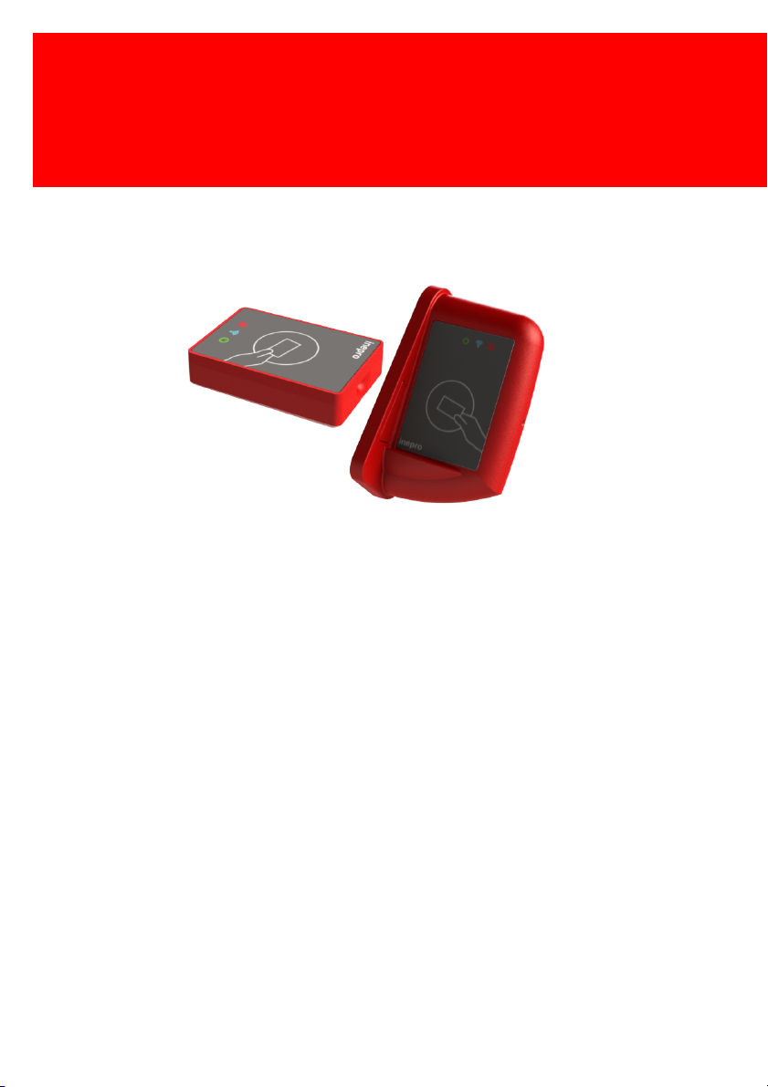
Inepro IP Reader (Konica Minolta)
The most versatile card reader solution
Congratulations on your selection of Inepro card readers. We are certain you will be
pleased with your purchase of one of the flexibele solutions of the market.
We want to help you get the best result from your Inepro Back Office Suite. This manual
contains information on how to do that; please read it carefully. Due to continuous
product improvements this manual is subject to changes without notice.
We strongly recommend you read the license agreement to fully understand its coverage
and your responsibilities of ownership.
Your Inepro dealer is dedicated to your satisfaction and will be pleased to answer your
questions and your concerns.
Best wishes,
Inepro BV.

Inepro IP Reader (Konica Minolta)
All rights reserved. No parts of this work may be reproduced in any form or by any means graphic, electronic, or mechanical, including photocopying, recording, taping, or information
storage and retrieval systems - without the written permission of the publisher.
Products that are referred to in this document may be either trademarks and/or registered
trademarks of the respective owners. The publisher and the author make no claim to these
trademarks.
While every precaution has been taken in the preparation of this document, the publisher and
the author assume no responsibility for errors or omissions, or for damages resulting from the
use of information contained in this document or from the use of programs and source code that
may accompany it. In no event shall the publisher and the author be liable for any loss of profit
or any other commercial damage caused or alleged to have been caused directly or indirectly by
this document.
Version 2.0.1 created: November 2014 in Nieuw-Vennep.
Publisher
Inepro B.V.
Managing Editor
K. de Graaf
Technical Editors
P. Blom
R. de Koker
Cover Design
H. Wagenaar
K. de Graaf
Team Coordinator
R. Groen
Production
Inepro B.V.

Table of Contents
Introduction
Components
Operating Procedures
Communication
Network Connections
LEDs (Light Emitting Diodes)
Software configuration settings
Inepro Business Server
(Optional)
Specifications
Appendix I
2
5
8
10
13
16
21
29
34
37
Directives
ATTENTION!!
Read this manual carefully before installing the IP Reader!
Mains connection
Before connecting the appliance to the mains, check that the mains supply voltage corresponds
to the voltage printed on the type plate of the adapter. If the mains voltage is different, consult
your supplier.
Guarentee
No guarantee can be given if safety regulations are not followed.
Security
Always disconnect the power supply before handling anything inside the device.
Indoor User Only
This device may only be used indoors.
CE Conformité Europeène (Conform European Norm)
This device is in conformity with the EMC directive and low-voltage directive.
End of life directives
Inepro is paying a lot of attention to environmentally-friendly production. Your new device contain
materials which can be recycled and reused. At the end of its life specialised companies can
dismantle the discarded device to recycle the reusable materials and to minimise the amount of
materials to be disposed of. Please observe the local regulations regarding the disposal of
packaging materials, exhausted batteries and old equipment.
Version 2.0.1 - I

Introduction
Part
I

Introduction
Introduction
In this manual you find the instructions to install and configure your
IP-reader. This manual is meant for all the Konica Minolta
IP-readers.
This manual, the IP reader hardware and software are subject to
change, make sure you have the latest version of this manual,
because the older versions may have become obsolete.
Konica Minolta IP-readers:
· 361100 Inepro IP Card Reader Mifare KoMi
· 361101 Inepro IP Card Reader Mifare Desfire KoMi
· 361102 Inepro IP Card Reader Legic Prime KoMi
· 361103 Inepro IP Card Reader Legic Advant KoMi
· 361104 Inepro IP Card Reader HiD iClass KoMi
· 361105 Inepro IP Card Reader HiD Prox KoMi
· 361106 Inepro IP Card Reader HiD Indala KoMi
· 361107 Inepro IP Card Reader Multitag KoMi
Function
The purpose of the IP reader is to read the unique ID contained in
the card that is presented to the reader and transfer this ID to a
server. In most cases this data will be the card serial number. To
facilitate this a variety of card reader software module have been
developed. Our configuration tool will enable you to change the
setting on the IP reader board.
Version 2.0.1 - 2

Topics
The following topics will be addressed:
The components in the IP-reader set
1.
The operating procedures
2.
Network Connections
3.
Software configuration settings
4.
Connecting to the Business Server
5.
3 - Inepro IP Reader (Konica Minolta)

Components
Part
II
Components
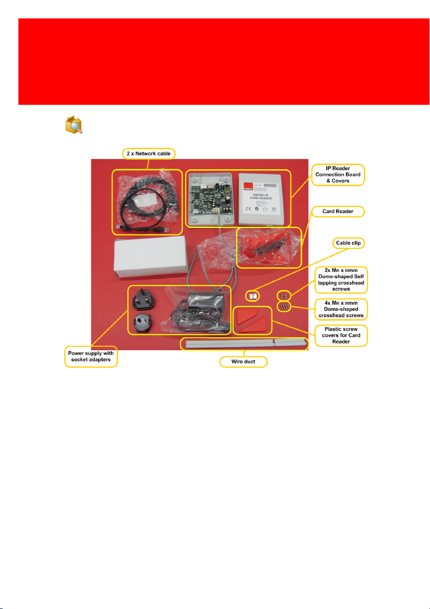
The IP Reader consists of the following components:
· Grey Card Reader Housing
Grey Antenna Box
-
Antenna Box Cap 1 / Grey
-
Antenna Box Cap 2 / Grey
-
· Controller Box
· Wire Duct - Grey
· Network Cables
Network Cable UTP C5E Patch Black (0,5mtr.)
-
Network Cable UTP C5E Patch Black (2,0mtr.)
-
5 - Inepro IP Reader (Konica Minolta)

Components
· Power Supply AC/DC 12 Volts, 7 Watt
Power Supply Unit
-
3x Socket Adapter
-
· Screw set
2x Screw self tapping cross head dome 3,5 x 9,5 mm
-
· Download Guide Inepro Manuals
· Cable clip
Cable clip PK 250
-
Self Adhesive Fastener 6 x 6 mm
-
Check Components
Please check if all the components are in the set before you
continue with the installation and setup.
Some parts are already pre-assembled or have already be
mounted. Like the Antenna board that is mounted in the
pre-assembled Grey Card Reader housing (the grey antenna box).
Version 2.0.1 - 6

Operating Procedures
Part
III
Operating Procedures
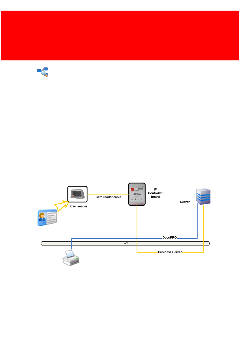
Operating Procedures
The card reader is connected to the IP controller board by the card
reader cable. Using this cable the IP controller board
communicates with the card reader. When a card is presented to
the reader it will read the card’s data. The IP controller board
makes a request to the card reader for the data. The IP controller
board will then transfer this information to the server by means of
an Ethernet connection. The server will receive the card’s data and
returns an (error) code to the IP controller board.
Version 2.0.1 - 8
 Loading...