

Page 1

1156SBT000AA
EP5000/EP4000
TROUBLESHOOTING
Page 2
1139SBT0100A
INTRODUCTION1
1139SBT0101A
1-1. General Precautions
1. When servicing thecopier with its covers removed, use utmost care to prevent your hands, clothing, and
tools from being caught in revolving parts including the chains and gears. When servicing the copier with
the Lower Rear Cover removed, be sure to install the jig.
2. Before attempting to replace parts and unplugging connectors, make sure that the power cord of the copier has been unplugged from the wall outlet.
3. Never create a closed circuit across connector pins except those specified in the text and on the printed
circuit.
4. When creating a closed circuit and measuring a voltage across connector pins specified in the text, be
sure to use the green wire (GND).
5. When the user is using a word processor or personal computer from the wall outlet of the same line, take
necessary steps to prevent the circuit breaker from opening due to overloads.
6. Keep all disassembled parts in good order and keep tools under control so that none will be lost or damaged.
1139SBT0102A
1-2. How to Use This Book
1. If a component on a PWB or any other functional unit including a motor is defective, the text only instructs
you to replace the whole PWB or functional unit and does not give troubleshooting procedures applicable
within the defective unit.
2. All troubleshooting procedures contained herein assume that there are no breaks in the harnesses and
cords and all connectors are plugged into the right positions.
3. For the removal procedures of covers and parts, see DIS/REASSEMBLY, ADJUSTMENT.
4. The troubleshooting procedures are given in the order of greater frequency of trouble or order of operation.
5. The procedures preclude possible malfunctions due to noise and other external causes.
1139SBT0103A
1-3. Reading the Text
1. The paper transport failure troubleshooting procedures are given according to the symptom. First identify
the location where the paper is present and start the procedure for that particular location. For malfunction
troubleshooting, start with step 1 and onward.
2. Make checks in numerical order of steps and, if an item is checked okay, go to the next step.
Pattern 1 Pattern 2
Check ItemStep Result Action
12Is...? YES Do this.
↑↑↑↑
Go to step 2 if you answered NO.
1
2
T-1
Check ItemStep Result Action
Is...? YES
Go to step 2 if it checks okay.
Do this.
NO Check that.
↑↑↑↑
Page 3

1151SBT0200A
I/O PORT CHECK2
1156SBT0201A
2-1. Controlled Parts Check Procedure
To allow the Tech. Rep. to easily and safely determine whether a particular controlled part is fully operational, this copier provides the following provision: checking the data of the I/O port of the board IC with
the copier in the standby state (including a misfeed, malfunction, and closure failure condition) allows the
Tech. Rep. to determine whether a signal is properly input to, and output from, a controlled part.
<Procedure>
1) On the circuit diagram accompanying the text, locate the I/O port of the controlled part which is probably
defective when a misfeed or malfunction occurs.
2) Select the “IC Port Data Check” function of “I/O Check” in the Tech. Rep. mode and access the screen
which contains the port identified in step 1 above. (See SWITCHES ON PWBs/TECH. REP. MODE.)
3) Change or check the input or output port data to determine whether the controlled part is operational
and signals are properly input and output.
4) If the controlled part does not operate properly after changing the output port data, select “Controller
Board Check” of “I/O Check” in the Tech. Rep. mode and determine whether the board is responsible
for that malfunction or not.
Note: Only the output ports given on pages T-37 and 38 may be checked by “Controller Board Check”
of “I/O Check” in the Tech. Rep. mode.
T-2
Page 4

<Controlled Part Check Procedure by Changing Input Port Data>
Example: When a paper misfeed occurs in the paper take-up section of the copier,1st Drawer Pa-
<Procedure>
1) Remove the sheet of paper misfed and reset the misfeed.
2) From the I/O port check list, it is found that the H/L input signal to PC56 is supplied from PWB-A
3) Select “IC Port Check” from the I/O Check function in the Tech. Rep. mode and access the
4) Check that the input port data of PWB-A (IC3A) APB3 on the screen is “H” (sensor being un-
5) Move the PC56 actuator to block the sensor.
6) Return to the “I/O Check” basic screen once, select “IC Port Check” again, choose the screen
per Take-Up Sensor PC56 is considered to be responsible for it.
(IC3A) APB3.
screen which includes the input ports of PWB-A (IC3A) APB3.
blocked).
which includes the APB3 input port data, and make sure that the data has changed from “H”
to “L”.
L: PC56 is operational. H: PC56 is faulty.
T-3
Page 5

<Controlled Part Check Procedure by Changing Output Port Data>
Example: When a manual paper misfeed occurs, Manual Feed Paper Take-Up Clutch CL3 is con-
<Procedure>
1) Remove the sheet of paper misfed and reset the misfeed.
2) From the I/O port check list, it is found that the ON/OFF output signal of CL3 is supplied from
3) Select “IC Port Check” from the I/O Check function in the Tech. Rep. mode and access the
4) Check that the output port data of PWB-A (IC5A) BPA1 on the screen is “1” (CL3 is deener-
5) Touch the “CHANGE” key on the screen to change the data from “1” to “0”, causing CL3 to be
6) If CL3 was not energized, make the “Controller Board Check” in the same mode (for some elec-
7) If the “ON” signal of CL51 is not output from PWB-A, the corresponding malfunction code is
sidered to be responsible for it.
PWB-A (IC5A) BPA1.
screen which includes the output ports of PWB-A (IC5A) BPA1.
gized).
energized for approx. 5 seconds. This allows you to determine whether the Clutch is “operational or faulty” by checking for the Clutch sound.
Operational: Sound produced. Faulty: No sound produced.
trical parts only).
displayed.
* For CL3, “C0337” is displayed.
T-4
Page 6
1156SBT0202A
2-2. I/O Port Check List
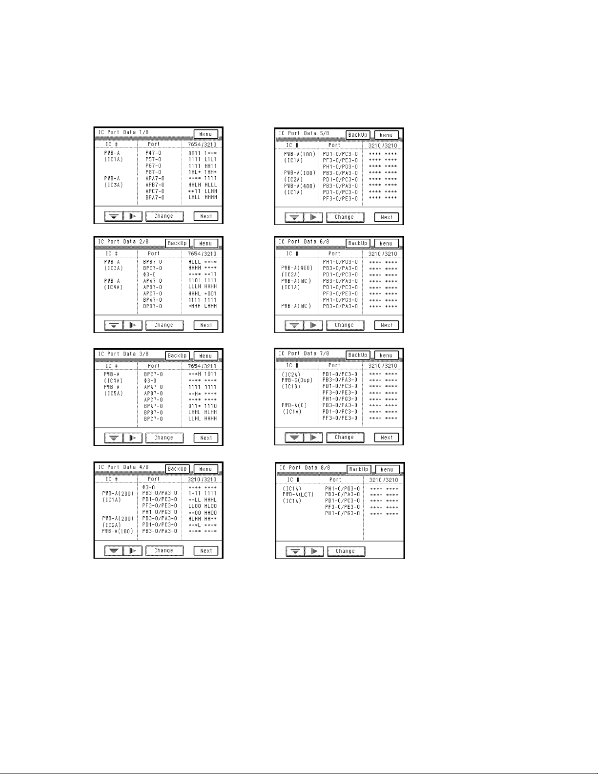
<Port Check Screens>
The following screens are displayed in the standby mode but may not always be as shown below
D
because some port data are undefined. (Copier+PF-205)
1156T016CA
1156T017CA
1156T018CA
1156T020CA
1156T021CA
1156T022CA
1156T019CA
1156T023CA
T-5
Page 7
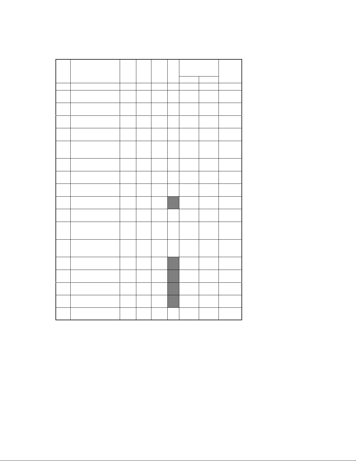
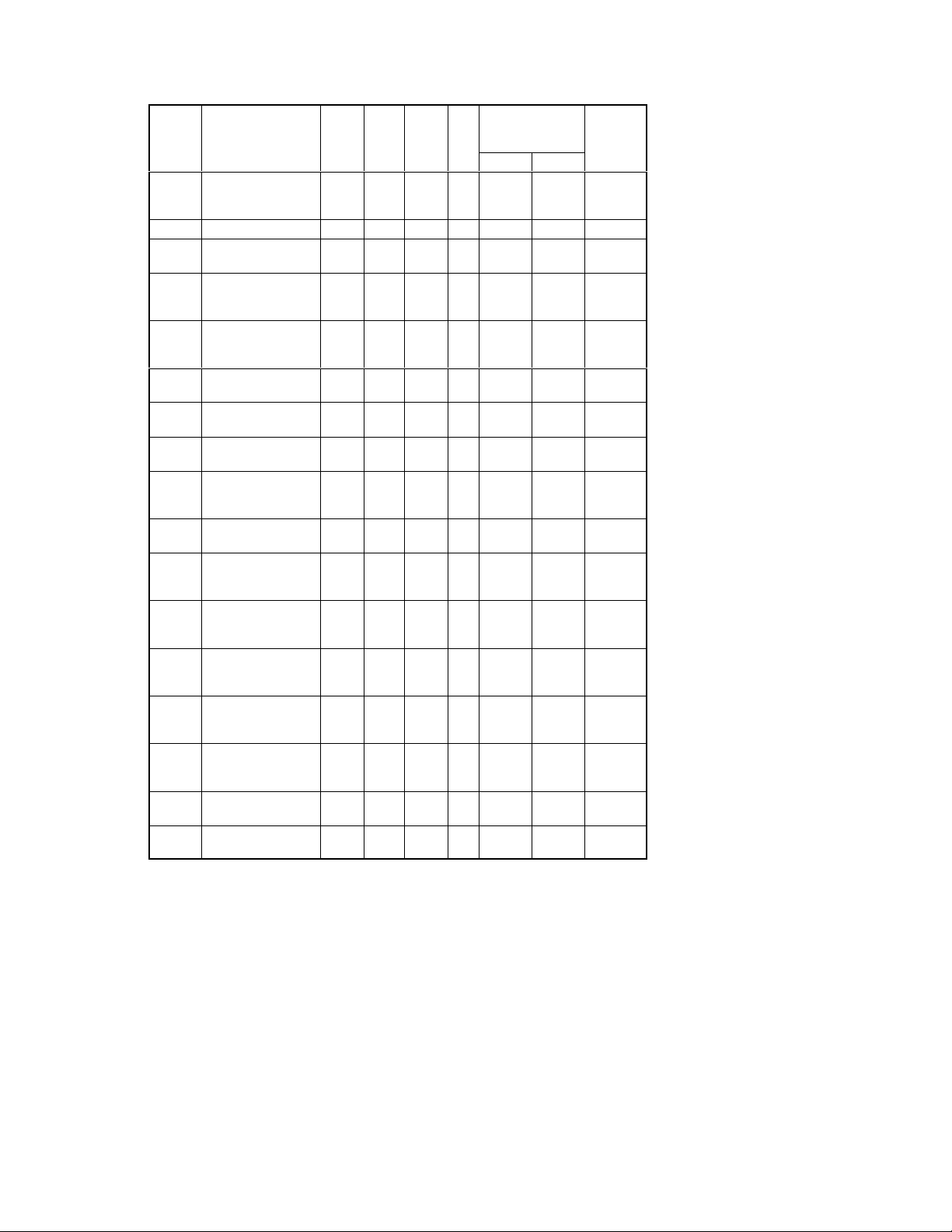
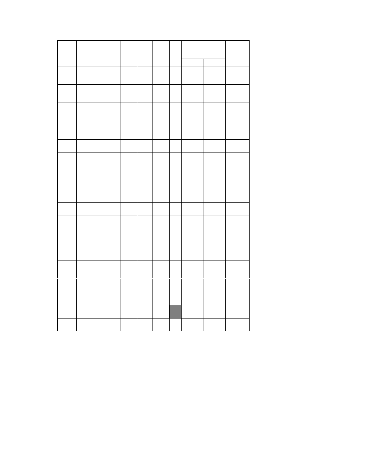
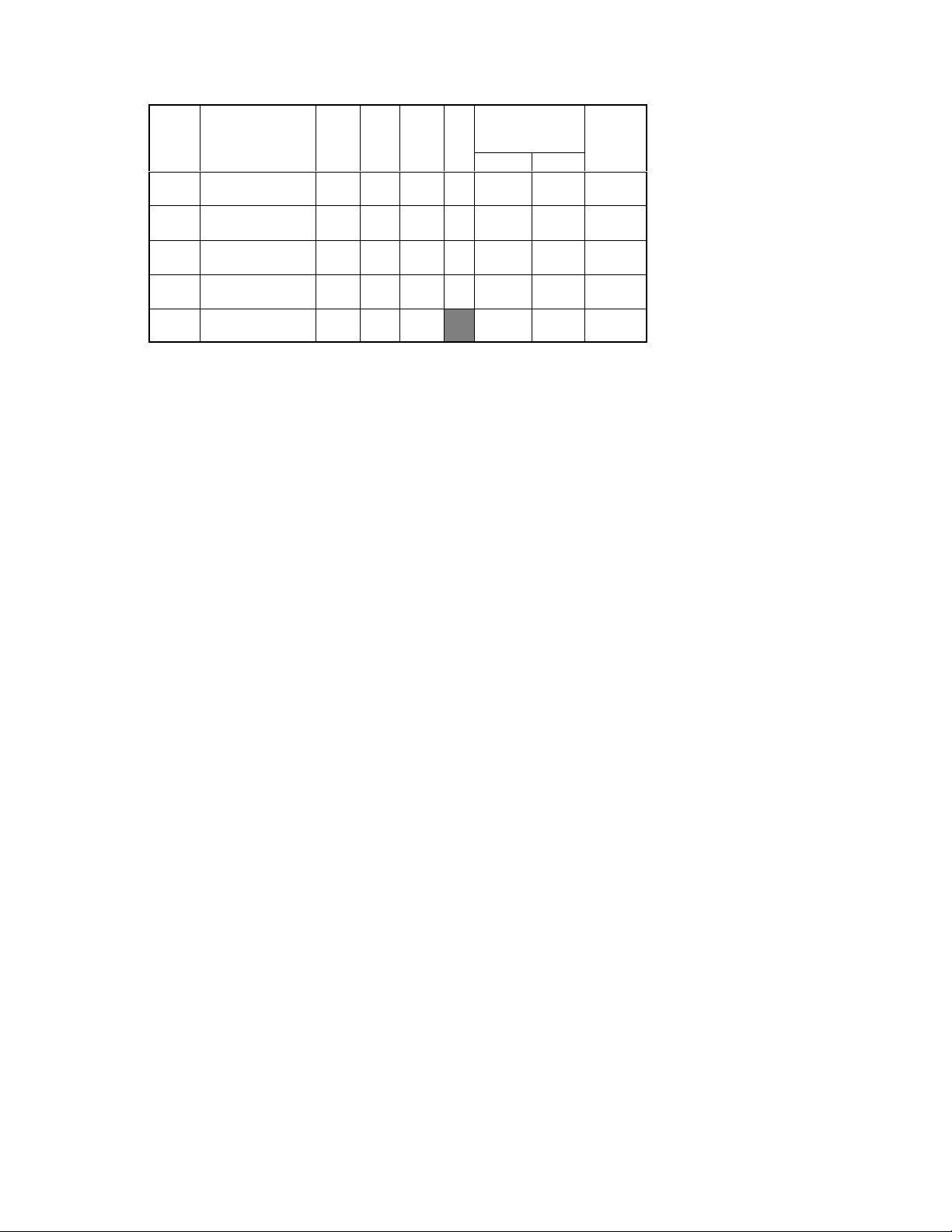
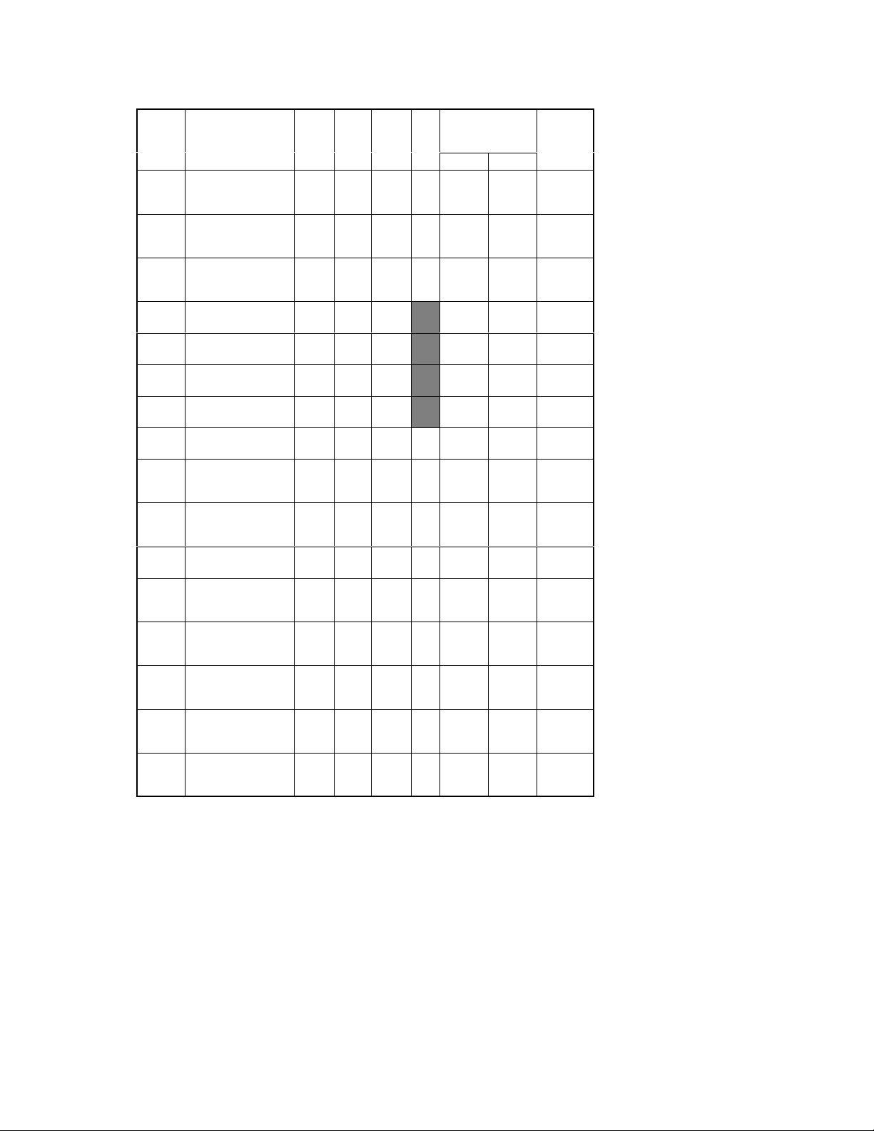
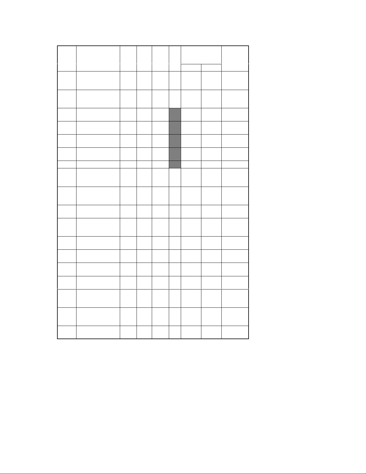
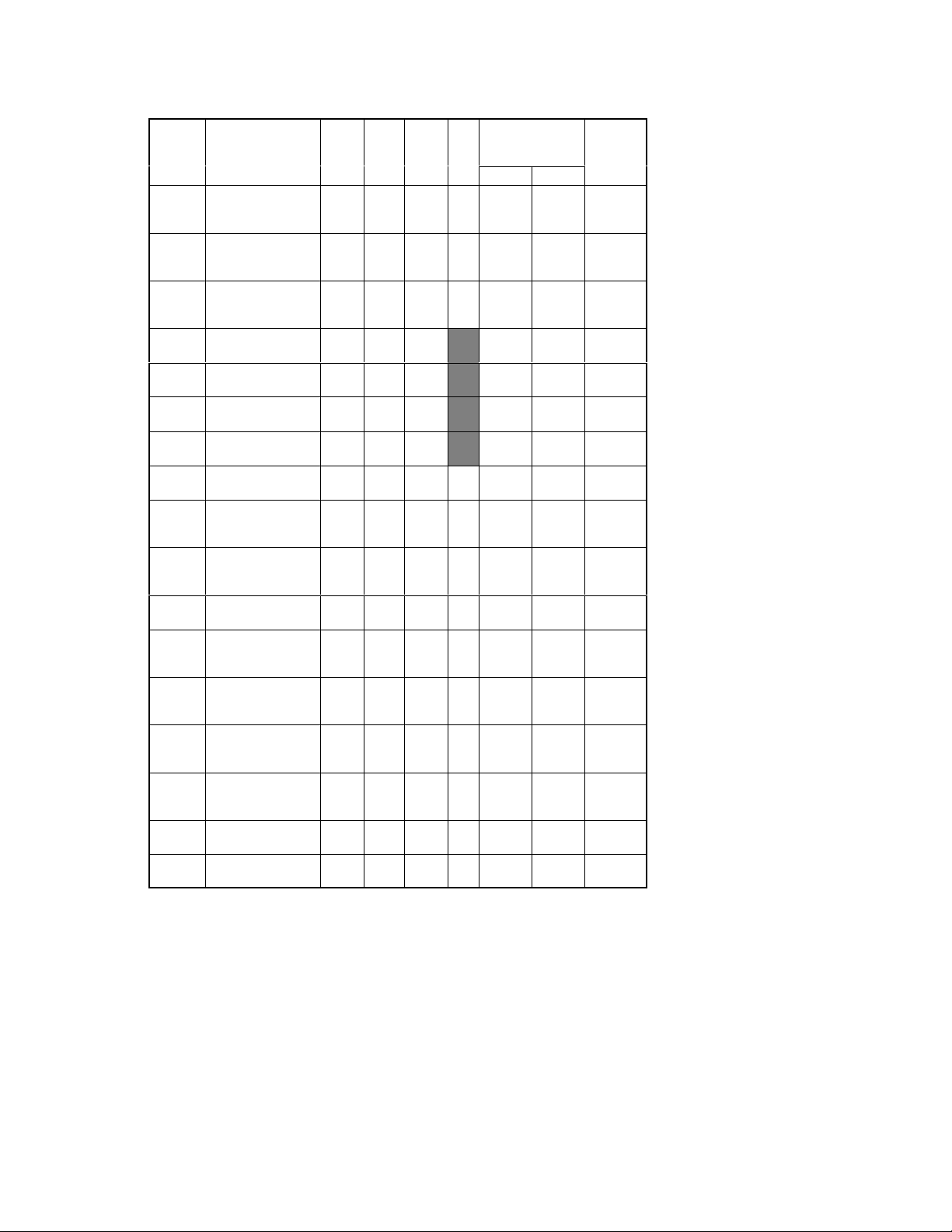
<I/O Port Check List>
bol
No.No
No
Copier *The shaded areas of the following table indicate that the output check cannot be made by
touching the Change key.
Sym-
M11
M12
M13
M14
M15
Parts/Signal Name
bol
M1 Main Drive Motor/REM 2/8 IC4A BPA2
Main Drive Motor/lock
↑↑↑↑
signal
M2 Scanner Motor/SCAN 3/8 IC4A APC0
Ventilation Fan Motor/
M3
REM
Ventilation Fan Motor/
↑↑↑↑
lock signal
Suction Fan Motor/se-
M4
lect signal
Suction Fan Motor/lock
↑↑↑↑
signal
Original Glass Cooling
M5
Fan Motor/REM
Original Glass Cooling
↑↑↑↑
Fan Motor/lock signal
Main Hopper Toner Re-
M8
plenishing Motor/REM
Sub Hopper Toner Re-
M9
plenishing Motor/REM
1st Drawer Paper TakeUp Motor
2nd Drawer Paper TakeUp Motor
1st Drawer Paper Lift-Up
Motor (UP)
1st Drawer Paper Lift-Up
↑↑↑↑
Motor (DOWN)
2nd Drawer Paper
Lift-Up Motor (UP)
2nd Drawer Paper
↑↑↑↑
Lift-Up Motor (DOWN)
Fusing Section Cooling
Fan Motor/REM
Dis-
IC
play
Page
2/8 IC4A BPB1
3/8 IC4A BPC1
2/8 IC4A BPB6
3/8 IC4A BPC2
3/8 IC4A BPC7
3/8 IC4A BPC0
2/8 IC4A BPB5
3/8 IC4A BPC3
3/8 IC5A APA2
3/8 IC5A APA0
3/8 IC5A APA1
3/8 IC5A APA4
3/8 IC5A APA5
3/8 IC5A APA6
3/8 IC5A APA7
3/8 IC4A APC2
Port
No.
No.
Operation Char-
acteristics/Panel
I/O
.
f
f
f
f
f
f
f
f
f
f
f
f
f
f
Display
Hor1 Lor0
OFF ON PJ18A-9
When
locked
Stop
OFF ON PJ34A-1
When
locked
Turned
at high
speed
When
locked
OFF ON PJ15A-5
When
locked
OFF ON PJ11A-4A
OFF ON PJ11A-2A
Turn in-
hibited
Turn in-
hibited
OFF ON (up) PJ18A-5
OFF
OFF ON (up) PJ8A-7
OFF
OFF ON PJ10A-1
When
turned
Scan
cycle
When
turned
Turned
at low
speed
When
turned
When
turned
Turn
per-
mitted
Turn
per-
mitted
ON
(down)
ON
(down)
CN/PJ
No.
PJ18A-10
PJ8A-5
PJ34A-3
PJ15A-4
PJ15A-3
PJ15A-7
PJ18A-1
PJ18A-2
PJ18A-6
PJ18A-8
.
T-6
Page 8
Dis-
No.No
No
Symbol Parts/Signal Name
Fusing Section Cooling Fan Motor/lock
↑↑↑↑
signal
SL1 Separator Solenoid 2/8 IC4A BPA0
Exit/Duplex Switching
SL5
Solenoid
Manual Feed Paper
Take-Up Solenoid
SL51
(UP)
Manual Feed Paper
Take-Up Solenoid
↑↑↑↑
(DOWN)
Paper Transport
CL1
Clutch
Synchronizing Roller
CL2
Clutch
Manual Feed Paper
CL3
Take-Up Clutch
Duplex Unit Vertical
PC12
Transport Sensor
Toner Bottle Home
PC35
Position Sensor
Manual Feed Paper
PC51
Empty Sensor
Transport Roller Sen-
PC54
sor
Paper Leading Edge
PC55
Detecting Sensor
1st Drawer Paper
PC56
Take-Up Sensor
2nd Drawer Paper
PC57
Take-Up Sensor
1st Drawer Set Sen-
PC61
sor
2nd Drawer Set Sen-
PC62
sor
Page
IC
play
No.
3/8 IC4A APB6
2/8 IC4A BPA5
3/8 IC5A BPA2
3/8 IC5A BPA3
2/8 IC4A BPA3
2/8 IC4A BPA4
3/8 IC5A BPA1
3/8 IC5A BPB0
3/8 IC4A BPC5
3/8 IC5A BPB1
3/8 IC5A BPB6
3/8 IC5A BPB5
1/8 IC3A APB3
1/8 IC3A APB4
1/8 IC3A BPA5
1/8 IC3A APB5
Port
No.
Operation Char-
acteristics/Panel
I/O
.
f
f
f
f
f
f
f
Display
Hor1 Lor0
When
locked
OFF ON PJ11A-6A
OFF ON PJ14A-6
OFF
OFF
OFF ON PJ14A-2
OFF ON PJ14A-4
OFF ON PJ15A-12
Paper
present
Un-
blocked
Paper
present
Paper
present
Paper
present
Paper
present
Paper
present
Out of
positionInposition
Out of
positionInposition
(down)
not
present
Blocked PJ11A-9
not
present
not
present
not
present
not
present
not
present
When
turned
ON
(up)
ON
Paper
Paper
Paper
Paper
Paper
Paper
CN/PJ
No.
.
PJ10A-3
PJ15A-10
PJ15A-9
PJ17A-8
PJ15A-14
PJ19A-5
PJ19A-2
PJ21A-5A
PJ21A-5B
PJ22A-2
PJ22A-6
T-7
Page 9
Sym-
bol
No.No
No
Parts/Signal Name
bol
1st Drawer Vertical
PC63
Transport Sensor
2nd Drawer Vertical
PC64
Transport Sensor
1st Drawer Lift-Up
PC65
Sensor
2nd Drawer Lift-Up
PC66
Sensor
1st Drawer Lift-Up
PC67
Motor Pulse Sensor
2nd Drawer Lift-Up
PC68
Motor Pulse Sensor
1stDrawer Lower
Limit Position Sen-
PC69
sor
2ndDrawer Lower
Limit Position Sen-
PC70
sor
Paper Size Detect-
PC72
ing Sensor 5
Paper Size Detect-
PC73
ing Sensor 6
Scanner Reference
PC81
Position Sensor
PC101
PC102
PC111
PC112
1st Drawer Paper
Empty Sensor
2nd Drawer Paper
Empty Sensor
Original Cover
Detecting Sensor
Toner Hopper Home
Position Sensor
CNT1 Total Counter/REM 1/8 IC1A P55
Total Counter/Set 2/8 IC4A APB7
↑↑↑↑
Dis-
IC
play
Page
1/8 IC3A APB6
1/8 IC3A APB7
1/8 IC3A APB1
1/8 IC3A APB2
1/8 IC3A APC0
1/8 IC3A APC1
1/8 IC3A BPA2
1/8 IC3A BPA3
2/8 IC3A BPB6
2/8 IC3A BPB7
2/8 IC4A APC4
1/8 IC3A APC2
1/8 IC3A APC3
2/8 IC4A APB5
3/8 IC5A BPB7
Port
No.
No.
Operation Charac-
teristics/Panel Dis-
I/O
.
f
play
Hor1 Lor0
Paper
not
present
Paper
not
present
Not at
upper
limit
Not at
upper
limit
Un-
blocked
Un-
blocked
Not at
lower
limit
Not at
lower
limit
Size not
detected
Size not
detected
Not at
home
Paper
not
present
Paper
not
present
Raised Lowered PJ12A-1
Not at
home
Normally
Out of
position
Paper
present
Paper
present
At up-
per limit
At up-
per limit
Blocked PJ23A-2
Blocked PJ23A-5
At lower
limit
At lower
limit
Size de-
tected
Size de-
tected
At home PJ8A-4
Paper
present
Paper
present
At home PJ11A-9B
When
counting
In posi-
tion
CN/PJ
No.
.
PJ21A-8A
PJ21A-8B
PJ21A-2A
PJ21A-2B
PJ24A-5
PJ24A-6
PJ25A-2
PJ25A-5
PJ23A-9
PJ23A-12
PJ13A-6
−
T-8
Page 10

Sym-
bol
No.No
No
CNT2 Plug-In Counter/REM 1/8 IC1A P44
RY1 Main Relay 1/8 IC1A P46
LA1
LA2
LA2
S21
S22
S23
S53 Paper Exit Switch 3/8 IC4A BPB2
S61
S62
S63
S64
S106
Parts/Signal Name
bol
Plug-In Counter/Set 3/8 IC5A BPC3
↑↑↑↑
H1 Fusing Heater Lamp 1/8 IC1A P57
Paper Dehumidifying
H3
Heater
Exposure Lamp/AVR
REM
Main Erase Lamp/
REM
Main Erase Lamp/
failure detection
S1 Power Switch 1/8 IC1A P53
Front Door Interlock
Switch
Right Upper Door
Interlock Switch
Left Upper Door
Interlock Switch
Paper Size Detecting
Switch 1
Paper Size Detecting
Switch 2
Paper Size Detecting
Switch 3
Paper Size Detecting
Switch 4
Toner Empty
Detecting Switch
Dis-
IC
No.
Port
No.
play
Page
1/8 IC1A P45
1/8 IC1A P61
2/8 IC4A BPA1
2/8 IC4A APC7
1/8 IC1A P51
3/8 IC5A BPB2
3/8 IC5A BPC6
1/8 IC3A BPA6
1/8 IC3A BPA7
2/8 IC3A BPB4
2/8 IC3A BPB5
3/8 IC1A BPC6
Operation Charac-
teristics/Panel Dis-
I/O
.
f
f
f
f
f
f
play
Hor1 Lor0
When
Normally
Out of
positionInposition
OFF ON PJ33A-2
ON OFF PJ4A-5
ON OFF PJ4A-3
OFF ON PJ8A-13
OFF ON PJ12A-3
OFF ON PJ12A-5
OFF ON PJ4A-1
OFF ON PJ4A-4
OFF ON PJ16A-2
OFF ON PJ16A-4
Paper
present
Size yet
to be de-
tected
Size yet
to be de-
tected
Size yet
to be de-
tected
Size yet
to be de-
tected
Toner
still avail-
able
count-
ing
Paper
not
present
Size de-
tected
Size de-
tected
Size de-
tected
Size de-
tected
Toner
empty
CN/PJ
No.
.
PJ28A-9
PJ28A-7
PJ20A-12
PJ26A-2
PJ26A-4
PJ26A-7
PJ26A-9
PJ11A-8B
T-9
Page 11
Sym-
bol
No.No
No
bol
UN5
↑↑↑↑
UN6
↑↑↑↑
PWB-G
Parts/Signal Name
1st Drawer Paper
Descent Key
Manual Down
Display 1
2ndDrawer Paper
Descent Key
Manual Down
Display 2
AIDC Sensor Board/
AIDC REM
Dis-
IC
No.
Port
No.
play
Page
1/8 IC3A BPA0
1/8 IC3A APC4
1/8 IC3A BPA1
1/8 IC3A APC5
2/8 IC4A APA4
Operation Charac-
teristics/Panel Dis-
I/O
.
f
f
f
play
Hor1 Lor0
OFF ON PJ24A-3
OFF ON PJ24A-1
OFF ON PJ24A-4
OFF ON PJ24A-2
OFF ON −
CN/PJ
No.
.
T-10
Page 12
PF-205
No.No
No
Symbol
M21
M22
M23
M24
M25
PC11
PC13
PC17
PC18
PC19
PC20
PC21
PC22
PC23
Parts/Signal Name
Vertical Transport
Drive Motor
3rd Drawer Paper
Take-Up Motor
4th Drawer Paper
Take-Up Motor
3rd Drawer Paper
Lift-Up Motor
3rd Drawer Paper
↑↑↑↑
Lift-Up Motor
4th Drawer Paper LiftUp Motor
4th Drawer Paper Lift-
↑↑↑↑
Up Motor
Lower Left Door
Sensor
Duplex Unit Turnover
Path Sensor
Vertical Transport
Sensor 3
Lower Right Door
Sensor
3rd Drawer Paper
Lift-Up Sensor
3rd Drawer Paper
Empty Sensor
3rd Drawer Paper
Take-Up Sensor
Vertical Transport
Sensor 4
4th Drawer Paper LiftUp Sensor
Dis-
IC
play
No.
Page
4/8 IC1A PB3
4/8 IC1A PB1
4/8 IC1A PB0
4/8 IC1A PA0
4/8 IC1A PA1
4/8 IC1A PA2
4/8 IC1A PA3
4/8 IC2A PB1
4/8 IC2A PB0
4/8 IC1A PC3
4/8 IC1A PE2
4/8 IC1A PG3
4/8 IC1A PC0
4/8 IC1A PE3
4/8 IC1A PC2
4/8 IC1A PF3
Port
No.
Operation Char-
acteristics/Panel
I/O
.
f
f
f
f
f
f
f
Display
Hor1 Lor0
Turn in-
hibited
Turn in-
hibited
Turn in-
hibited
OFF
OFF
Out of
positionInposition
Paper
not
present
Paper
not
present
Out of
positionInposition
Not at
upper
limit
Paper
not
present
Paper
not
present
Paper
not
present
Not at
upper
limit
Turn
per-
mitted
Turn
per-
mitted
Turn
per-
mitted
− ON (up) PJ9A-8B
ON
(down)
− ON (up) PJ9A-2A
ON
(down)
Paper
present
Paper
present
At up-
per limit
Paper
present
Paper
present
Paper
present
At up-
per limit
CN/PJ
No.
.
PJ12A-1~
4
PJ11A-1~
4
PJ10A-1~
4
PJ9A-7B
PJ9A-1A
PJ3A-2
PJ3A-5
PJ7A-5
PJ7A-2
PJ6A-12
PJ6A-2
PJ6A-9
PJ6A-5
PJ8A-8
T-11
Page 13

Symbol Parts/Signal Name
No.No
No
4th Drawer Paper
PC24
Empty Sensor
3rd Drawer Set
PC25
Sensor
4th Drawer Set
PC26
Sensor
3rd Drawer Paper
Lift-Up Motor Pulse
PC27
Sensor
4th Drawer Paper LiftUp Motor Pulse
PC28
Sensor
4th Drawer Paper
PC29
Take-Up Sensor
Large Capacity Toner
Collecting Box Set
PC31
Sensor
Dis-
IC
play
No.
Page
4/8 IC1A PD0
4/8 IC1A PG2
4/8 IC1A PF2
4/8 IC1A PC1
4/8 IC1A PD1
4/8 IC2A PB3
4/8 IC2A PC3
Port
No.
Operation Char-
acteristics/Panel
I/O
.
Display
Hor1 Lor0
Paper
present
Out of
positionInposition
Out of
positionInposition
blocked
blocked
Paper
present
Paper
present
not
Un-
Un-
not
not
Paper
present
Blocked
Blocked
Paper
present
Paper
present
CN/PJ
No.
.
PJ8A-2
PJ9A-2B
PJ9A-7A
PJ9A-5B
PJ9A-4A
PJ8A-5
PJ2A-2
T-12
Page 14
PF-105
bol
No.No
No
Sym-
PC11
PC13
PC17
PC18
Parts/Signal Name
bol
Vertical Transport
M21
Drive Motor
3rd Drawer Paper
M22
Take-Up Motor
Main Tray Elevator
M26
Motor
Main Tray Elevator
↑↑↑↑
Motor
M27 Paper Shift Motor 5/8 IC1A PA 0
Paper Shift Motor 5/8 IC1A PA 1
↑↑↑↑
M28 Shift Gate Motor 5/8 IC1A PB2
Shift Tray Paper
PC1
Empty Sensor
Main Tray Lower
PC2
Position Sensor
Shifter Home
PC3
Position Sensor
Shifter Return
PC4
Position Sensor
Elevator Motor
PC5
Pulse Sensor
Shift Motor Pulse
PC6
Sensor
3rd Drawer Set
PC7
Sensor
Lower Left Door
Sensor
Duplex Unit Turnover Path Sensor
Vertical Transport
Sensor 3
Lower Right Door
Sensor
Dis-
IC
play
No.
Page
5/8 IC1A PB3
5/8 IC1A PB1
5/8 IC1A PA2
5/8 IC1A PA3
5/8 IC1A PD1
6/8 IC2A PC1
6/8 IC2A PC0
6/8 IC2A PD1
5/8 IC1A PF2
5/8 IC1A PD0
6/8 IC1A PG2
6/8 IC2A PB1
6/8 IC2A PB0
5/8 IC1A PC3
5/8 IC1A PE2
Port
No.
Operation Char-
acteristics/Panel
I/O
.
f
f
f
f
f
f
f
Display
Hor1 Lor0
Turn in-
hibited
Turn in-
hibited
Up/stop Down PJ4A-6B
Down/
stop
Trans-
fer/stop
Return/
stop
OFF ON PJ4A-2B
Paper
not
present
Not at
lower
limit
Not at
home
Not at
returned
position
Un-
blocked
Un-
blocked
Out of
positionInposition
Out of
positionInposition
Paper
not
present
Paper
not
present
Out of
positionInposition
Turn
per-
mitted
Turn
per-
mitted
Up PJ4A-7B
Return PJ4A-4B
Transfer PJ4A-5B
Paper
present
At
lower
limit
At home PJ4A-8A
At
returned
position
Blocked
Blocked
Paper
present
Paper
present
CN/PJ
No.
.
PJ12A-1~4
PJ11A-1~4
PJ4A-4A
PJ4A-9A
PJ4A-7A
PJ4A-5A
PJ4A-3A
PJ5A-2
PJ3A-2
PJ3A-5
PJ7A-5
PJ7A-2
T-13
Page 15

Sym-
bol
No.No
No
bol
PC19
PC20
PC21
PC22
PC31
PC34
PC35
PWB-E
UN21
SL41
Parts/Signal Name
3rd Drawer Paper
Lift-Up Sensor
3rd Drawer Paper
Empty Sensor
3rd Drawer Paper
Take-Up Sensor
Vertical Transport
Sensor 4
Large Capacity
Toner Collecting Box
Set Sensor
Shift Gate Position
Sensor
Lower Position
Sensor
Main Tray Paper
Empty Board
Drawer Paper
Descent Key
3rd Drawer Lock
Solenoid
Dis-
IC
play
No.
Page
6/8 IC1A PG3
5/8 IC1A PC0
5/8 IC1A PE3
5/8 IC1A PC2
4/8 IC2A PC3
5/8 IC1A PC1
6/8 IC2A PB3
5/8 IC1A PF3
6/8 IC2A PC2
6/8 IC2A PA1
Port
No.
Operation Char-
acteristics/Panel
I/O
.
f
Display
Hor1 Lor0
Not at
upper
limit
Paper
not
present
Paper
not
present
Paper
not
present
Out of
positionInposition
Un-
blocked
Not at
lower
limit
Paper
not
present
OFF ON PJ4A-10A
OFF ON PJ5A-5
At
upper
limit
Paper
present
Paper
present
Paper
present
Blocked
At lower
limit
Paper
present
CN/PJ
No.
.
PJ6A-12
PJ6A-2
PJ6A-9
PJ6A-5
PJ2A-2
PJ4A-1B
PJ4A-2A
PJ4A-6A
T-14
Page 16

AD-9
No.No
No
Symbol
M31
CL31
SL31
SL32
SL33
PC8
PC9
PC14
PC15
PC16
Parts/Signal Name
Duplex Unit Drive
Motor
Duplex Unit Drive
↑↑↑↑
Motor/lock signal
Duplex Unit Paper
Take-Up Clutch
Duplex Unit Gate
Switching Solenoid
Duplex Unit Rear
Finger Solenoid
Duplex Unit Pick-Up
Solenoid
Duplex Gate Home
Position Sensor
Front/Rear Edge
Guide Plate Home
Position Sensor
Duplex Unit Paper
Entry Sensor
Duplex Unit Paper
Empty Sensor
Duplex Unit Paper
Take-Up Sensor
Dis-
IC
play
No.
Page
7/8 IC1G PB3
7/8 IC1G PE1
7/8 IC1G PA3
7/8 IC1G PH1
7/8 IC1G PH0
7/8 IC1G PB2
7/8 IC1G PE0
7/8 IC1G PC3
7/8 IC1G PC1
7/8 IC1G PC2
7/8 IC1G PC0
Port
No.
Operation Char-
acteristics/Panel
I/O
.
f
f
f
f
f
Display
Hor1 Lor0
OFF ON PJ6G-2
When
locked
present
present
present
When
turned
OFF ON PJ2G-7
OFF ON PJ3G-5
OFF ON PJ3G-7
OFF ON PJ2G-12
Not at
Not at
Paper
Paper
Paper
home
home
not
not
not
At home PJ7G-2
At home PJ7G-5
Paper
present
Paper
present
Paper
present
CN/PJ
No.
PJ6G-1
PJ3G-2
PJ2A-4
PJ2G-9
.
T-15
Page 17

C-301
No.No
No
Dis-
Symbol
HMOT Elevator Motor 8/8 IC1A PH0
PWB-B
EMP-
SEN
KSEN Paper Feed Sensor 8/8 IC1A PG0
LEV-
SEN
LOW-
SEN
DSEN
SET-
SEN
Parts/Signal Name
Elevator Motor 8/8 IC1A PH1
↑↑↑↑
Paper Plate Descent
Switch Board
Paper Empty Sensor 8/8 IC1A PC1
Paper Plate Raised
Position Sensor
Paper Plate Lowered
Position Sensor
Cassette Door
Sensor
Set Sensor 8/8 IC1A PC2
Page
IC
play
No.
8/8 IC1A PG1
8/8 IC1A PC0
8/8 IC1A PG3
8/8 IC1A PG2
Port
No.
Operation Char-
acteristics/Panel
I/O
.
f
f
Display
Hor1 Lor0
Down/
stop
Up/stop Down CN5A-1
OFF ON CN2A-2
Paper
present
Paper
present
Not upper limit
Not at
lower
limit
Out of
position
Out of
positionInposition
Up CN5A-2
Paper
not
present
Paper
not
present
At up-
per limit
At lower
limit
In posi-
tion
CN/PJ
No.
.
CN2A-5
CN2A-3
CN2A-6
CN3A-5
CN3A-2
CN2A-4
T-16
Page 18
PF205 : MC
No.No
No
Symbol
M21
M22
M23
M24
↑↑↑↑
M25
↑↑↑↑
PC11
PC13
PC17
PC18
PC19
PC21
PC22
PC23
PC25
PC26
Parts/Signal Name
Vertical Transport
Drive Motor
3rd Drawer Paper
Take-Up Motor
4th Drawer Paper
Take-Up Motor
3rd Drawer Paper
Lift-Up Motor
3rd Drawer Paper
Lift-Up Motor
4th Drawer Paper
Lift-Up Motor
4th Drawer Paper
Lift-Up Motor
Lower Left Door
Sensor
Duplex Unit Turnover Path Sensor
Vertical Transport
Sensor 3
Lower Right Door
Sensor
3rd Drawer Paper
Lift-Up Sensor
3rd Drawer Paper
Take-Up Sensor
Vertical Transport
Sensor 4
4th Drawer Paper
Lift-Up Sensor
3rd Drawer Set
Sensor
4th Drawer Set
Sensor
Dis-
IC
play
No.
Page
6/8 IC1A PB3
6/8 IC1A PB1
6/8 IC1A PB0
6/8 IC1A PA0
6/8 IC1A PA1
6/8 IC1A PA2
6/8 IC1A PA3
6/8 IC2A PB1
6/8 IC2A PB0
6/8 IC1A PC3
6/8 IC1A PE2
6/8 IC1A PG3
6/8 IC1A PE3
6/8 IC1A PC2
6/8 IC1A PF3
6/8 IC1A PG2
6/8 IC1A PF2
Port
No.
Operation Char-
acteristics/Panel
I/O
.
f
f
f
f
f
f
f
Display
Hor1 Lor0
Turn in-
hibited
Turn in-
hibited
Turn in-
hibited
OFF ON (up) PJ9A-8B
OFF ON (up) PJ9A-7B
OFF ON (up) PJ9A-2A
OFF ON (up) PJ9A-1A
Out of
positionInposition
Paper
not
present
Paper
not
present
Out of
positionInposition
Not at
upper
limit
Paper
not
present
Paper
not
present
Not at
upper
limit
Out of
positionInposition
Out of
positionInposition
Turn
per-
mitted
Turn
per-
mitted
Turn
per-
mitted
Paper
present
Paper
present
upper
limit
Paper
present
Paper
present
upper
limit
CN/PJ
No.
.
PJ12A-1~
4
PJ11A-1~
4
PJ10A-1~
4
PJ3A-2
PJ3A-5
PJ7A-5
PJ7A-2
At
PJ6A-12
PJ6A-9
PJ6A-5
At
PJ8A-8
PJ9A-2B
PJ9A-7A
T-17
Page 19

Symbol Parts/Signal Name
No.No
No
PC29
PC31
PC67
PC68
PC69
PC70
PWB-E1
PWB-E2
UN5
UN6
4th Drawer Paper
Take-Up Sensor
Large Capacity Toner Collecting Box Set
Sensor
3rd Drawer Paper
Lift-Up Motor Pulse
Sensor
4th Drawer Paper
Lift-Up Motor Pulse
Sensor
3rd Drawer Lower
Position Sensor
4th Drawer Lower
Position Sensor
3rd Drawer Paper
Empty Board
4th Drawer Paper
Empty Board
3rdDrawer Paper
Descent Key
4thDrawer Paper
Descent Key
Dis-
IC
play
No.
Page
6/8 IC2A PB3
6/8 IC2A PC3
6/8 IC1A PC1
6/8 IC1A PD1
7/8 IC2A PD1
7/8 IC2A PC0
6/8 IC1A PC0
6/8 IC1A PD0
7/8 IC2A PC1
7/8 IC2A PC2
Port
No.
Operation Char-
acteristics/Panel
I/O
.
Display
Hor1 Lor0
Paper
present
Out of
positionInposition
blocked
blocked
Not at
lower
Not at
lower
Paper
present
Paper
present
OFF ON PJ4A-9A
OFF ON PJ4A-10A
not
present
Un-
Blocked
Un-
Blocked PJ9A-4A
limit
limit
not
present
not
present
Paper
lower
limit
lower
limit
Paper
Paper
CN/PJ
No.
.
PJ8A-5
PJ2A-2
PJ9A-5B
At
PJ4A-7A
At
PJ4A-8A
PJ4A-4A
PJ4A-3A
T-18
Page 20

PF-5D/AD-8
No.No
No
Symbol
M21
M31
↑↑↑↑
CL31
SL31
SL32
SL33
PC8
PC9
PC11
PC13
PC14
PC15
PC16
PC17
PC18
PC31
Parts/Signal Name
Vertical Transport
Drive Motor
Duplex Unit Drive
Motor
Duplex Unit Drive
Motor/lock signal
Duplex Unit Paper
Take-Up Clutch
Duplex Unit Gate
Switching Solenoid
Duplex Unit Rear
Finger Solenoid
Duplex Unit Pick-Up
Solenoid
Duplex Gate Home
Position Sensor
Front/Rear Edge
Guide Plate Home
Position Sensor
Lower Left Door
Sensor
Duplex Unit Turnover
Path Sensor
Duplex Unit Paper
Entry Sensor
Duplex Unit Paper
Empty Sensor
Duplex Unit Paper
Take-Up Sensor
Vertical Transport
Sensor 3
Lower Right Door
Sensor
Large Capacity Toner
Collecting Box Set
Sensor
Dis-
IC
play
No.
Page
4/8 IC1A PB3
7/8 IC1G PB3
7/8 IC1G PE1
7/8 IC1G PA3
7/8 IC1G PH1
7/8 IC1G PH0
7/8 IC1G FB2
7/8 IC1G PE0
7/8 IC1G PC3
5/8 IC2A PB1
5/8 IC2A PB0
7/8 IC1G PC1
7/8 IC1G PC2
7/8 IC1G PC0
5/8 IC1A PC3
5/8 IC1A PE2
5/8 IC2A PC3
Port
No.
Operation Char-
acteristics/Panel
I/O
.
f
f
f
f
f
f
Display
Hor1 Lor0
Turn in-
hibited
OFF ON PJ5G-2
When
locked
OFF ON PJ2G-7
OFF ON PJ3G-5
OFF ON PJ3G-7
OFF ON PJ2G-12
Not at
home
Not at
home
Out of
positionInposition
Paper
not
present
Paper
not
present
Paper
not
present
Paper
not
present
Paper
not
present
Out of
positionInposition
Out of
positionInposition
Turn
per-
mitted
When
turned
At home PJ7G-2
At home PJ7G-5
Paper
present
Paper
present
Paper
present
Paper
present
Paper
present
CN/PJ
No.
.
PJ12A-1~
4
PJ5G-1
PJ3A-2
PJ3A-5
PJ3G-2
PJ2G-4
PJ2G-9
PJ7A-5
PJ7A-2
PJ2A-2
T-19
Page 21
1151SBT0300A
PAPER TRANSPORT FAILURE3
1156SBT0301A
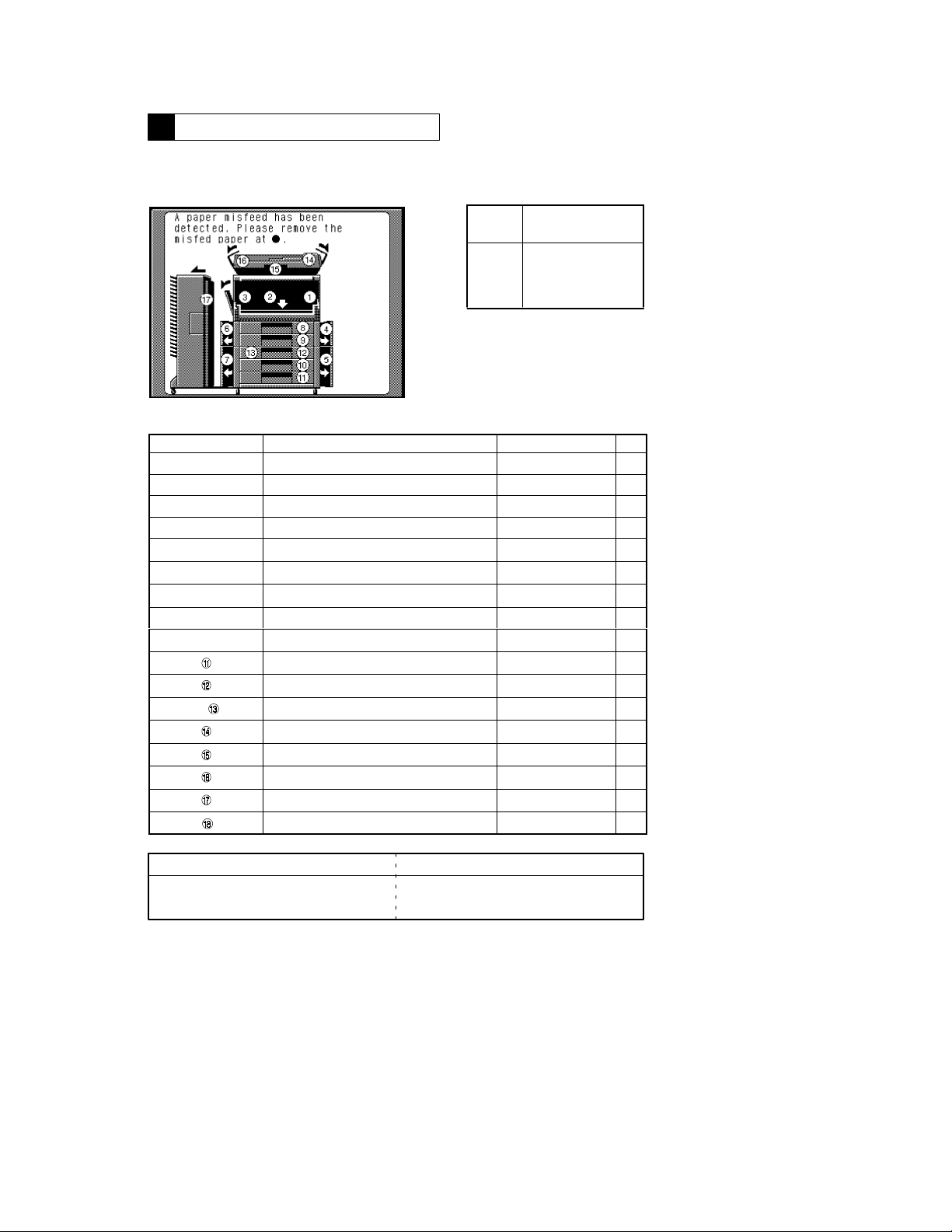
3-1. Paper Misfeed
When a paper misfeed occurs, the Touch Panel shows the corresponding message, misfeed location and
paper location.
Blinking
Light
Steady
Light
There is a misfeed at
that location.
There might be a
sheet of paper
stopped at that
location.
1149T002CA
Blinking/Steady LED
➀
➁
➂
➃
➃,➄
➅,➆
➇
➈
➉
,
➆
Multi Bypass take-up and transport T-22
Transport/separator T-20
Fusing/exit T-24
Copier take-up/vertical transport T-17,18
Paper Feed Cabinet take-up/vertical transport T-25 to 28
Duplex Unit vertical transport T-30
1st Drawer take-up T-17
2nd Drawer take-up T-17
3rd Drawer take-up T-25 to 28
4th Drawer take-up T-26
Duplex Unit take-up T-32,33
Duplex Unit storage T-31
ADF take-up −
ADF transport −
ADF turnover/exit −
Sorter −
LCC −
Misfeed/Paper Location Ref. Page
<Display Resetting Method>
When misfeed occurs in the copier Open and close the Front Door.
When misfeed occurs in the option (except Duplex Unit)
Raise and lower the option, or slide the option
away from, and back up against, the copier.
*When option is installed
*
*
*
*
*
*
*
*
*
*
*
T-20
Page 22
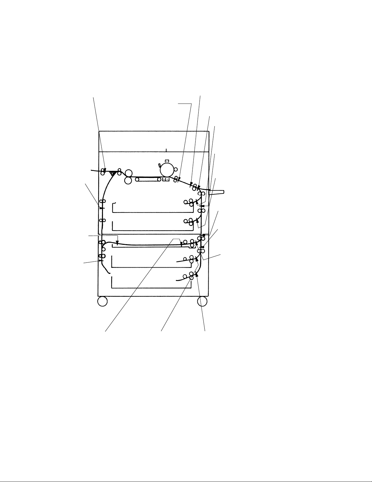
<Misfeed Detecting Sensor Layout>
*When options (PF-205+AD-9)
are installed
Paper Exit Sensor (S53)
*Duplex Unit
Vertical Transport
Sensor (PC12)
*Duplex Unit
Paper Entry
Sensor (PC14)
*Duplex Unit
Turnover Path
Sensor (PC13)
Paper Leading Edge Detecting
Sensor (PC54)
Transport Roller Sensor (PC54)
1st Drawer
Vertical Transport
Sensor (PC63)
1st Drawer Paper
Take-Up Sensor
(PC56)
2nd Drawer
Vertical Transport
Sensor (PC64)
2nd Drawer Paper
Take-Up Sensor
(PC57)
*Vertical Transport Detection
Sensor 3 (PC17)
*Vertical Transport Detection
Sensor 4 (PC22)
*Duplex Unit
Paper T ake-up
Sensor (PC16)
*Duplex Unit Paper
Empty Sensor
(PC15)
*3rd Drawer
Paper T ake-up
Sensor (PC21)
T-21
1156T001AB
*4th Drawer
Paper T ake-up
Sensor (PC29)
Page 23
1156SBT0302A
g
g
p
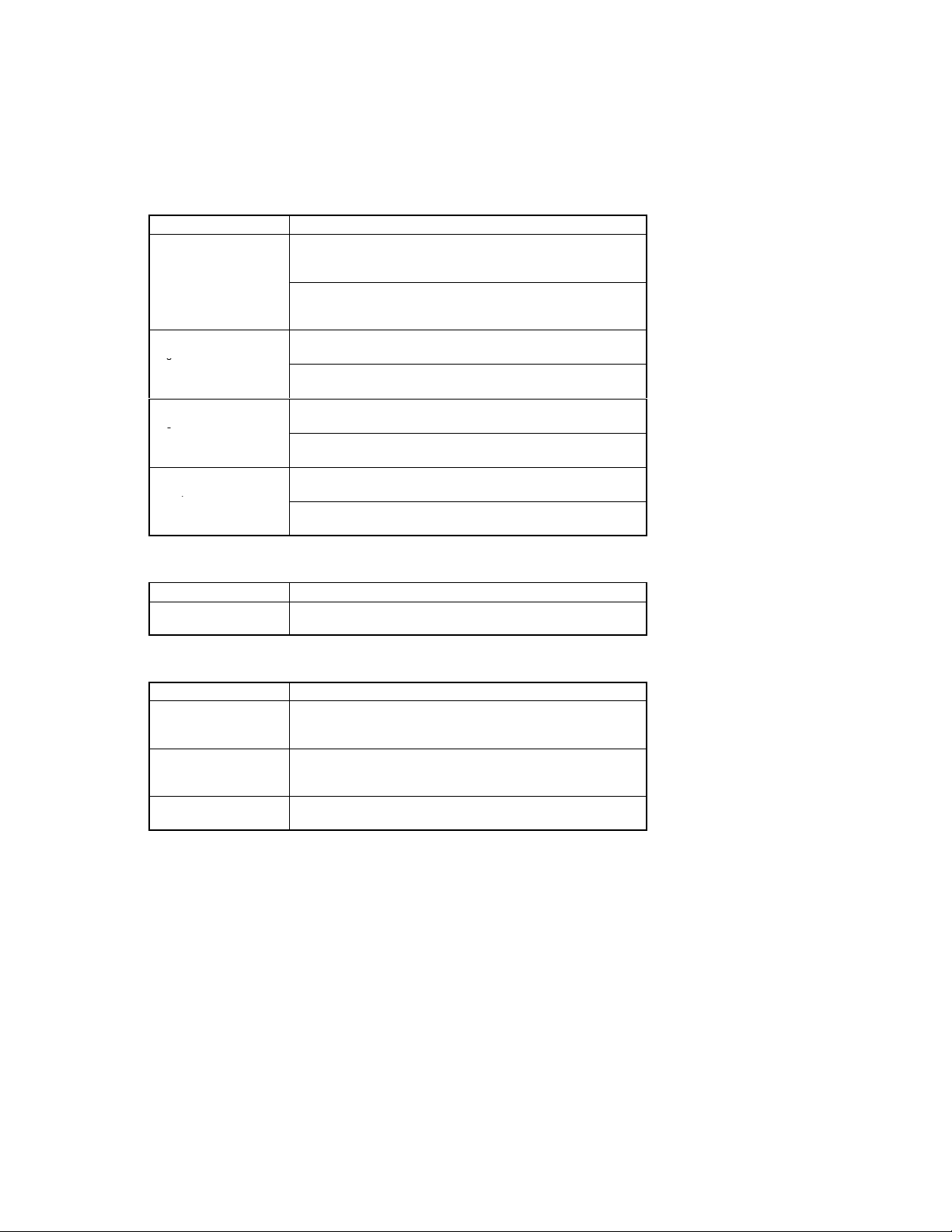
3-2. Misfeed Detection Types and Detection Timings
The following table lists the types of misfeed detection classified by the misfeed locations and their corre-
D
sponding detection timings.
Note: For the misfeed detection types and detection timings in the options, see the Service Manual for
the options.
<Copier Paper Take-up Misfeed>
Type Detection Timing
Paper take-up failure
detection
Paper take-up trailing
edge detection
Paper take-up leading
edge detection
Leading edge detection by
Transport Roller Sensor
PC54
1st Drawer Paper Take-Up Sensor PC56 is not blocked (L) even after
the lapse of approx. 2.2 sec. after 1st Drawer Paper Take-Up Motor M11
has been energized.
2nd Drawer Paper Take-Up Sensor PC57 is not blocked (L) even after
the lapse of approx. 2.2 sec. after 2nd Drawer Paper Take-Up Motor
M12 has been energized.
PC56 is not unblocked (H) even after the lapse of T (which varies for
paper sizes) after it has been blocked (L).
PC57 is not unblocked (H) even after the lapse of T (which varies for
paper sizes) after it has been blocked (L).
1st Drawer Vertical Transport Sensor PC63 is not blocked (L) even after
the lapse of approx. 2 sec. after PC56 has been blocked (L).
2nd Drawer Vertical Transport Sensor PC64 is not blocked (L) even
after the lapse of approx. 2 sec. after PC57 has been blocked (L).
PC54 is not blocked (L) even after the lapse of approx. 1.3 sec. after
PC63 has been blocked (L).
PC54 is not blocked (L) even after the lapse of approx. 1.7 sec. after
PC64 has been blocked (L).
<Multi-Bypass Misfeed>
Type Detection Timing
Paper take-up failure
detection
PC54 is not blocked (L) even after the lapse of approx. 2.5 sec. after
Manual Feed Paper Take-Up Clutch CL3 has been energized.
<Transport/Separator Misfeed>
Type Detection Timing
Trailing edge detection by
Transport Roller Sensor
PC54
Leading edge detection by
Paper Leading Edge Detecting Sensor PC55
Trailing edge detection by
PC55
PC54 is not unblocked (H) even after the lapse of T (which varies for
paper sizes) after the TRON signal has been input.
PC55 is not blocked (L) even after the lapse of approx. 1.2 sec. after
PC54 has been blocked (L).
PC55 is not unblocked (H) even after the lapse of approx. 1.2 sec. after
PC54 has been unblocked (H).
T-22
Page 24

<Fusing/Exit Misfeed>
Type Detection Timing
Leading edge detection by
Paper Exit Switch S53
Trailing edge detection by
S53
S53 is not deactuated even after the lapse of approx. 2 sec. after the
TRON signal has been input.
S53 is not actuated even after the lapse of approx. 2.5 sec. after PC55
has been unblocked (H).
T-23
Page 25
1156SBT0303A
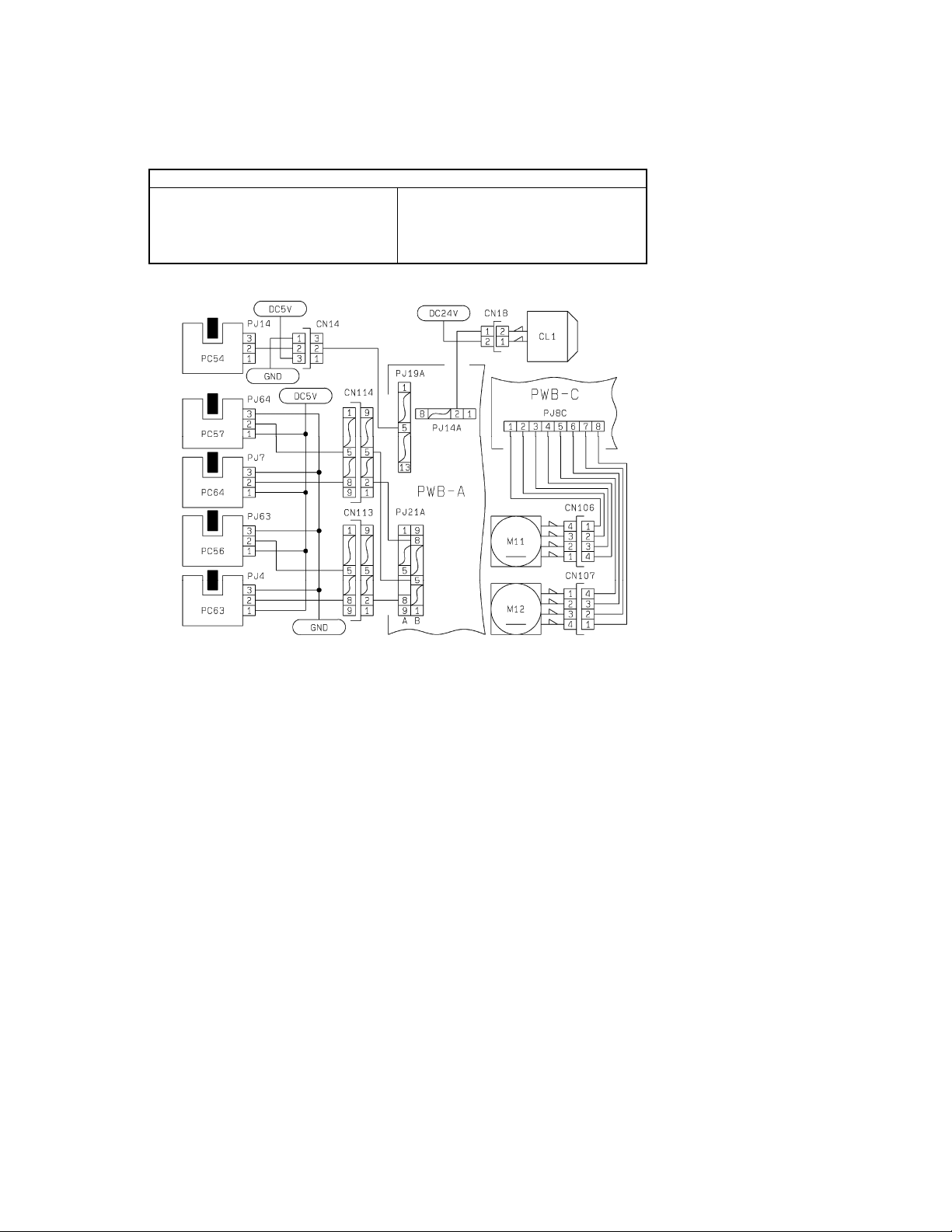
3-3. Misfeed Clearing Procedures
1156SBT030301A
1) Copier Paper Take-Up Misfeed
Relevant Electrical Parts
2nd Drawer Paper Take-Up Sensor PC57
D
1st Drawer Vertical Transport Sensor PC63
D
2nd Drawer Vertical Transport Sector PC64
D
Transport Roller Sensor PC54
D
1st Drawer Paper Take-Up Motor M11
D
2nd Drawer Paper Take-Up Motor M12
D
Paper Transport Clutch CL1
D
Power Supply Board PWB−C
D
Master Board PWB-A
D
T-24
1156C01TAA
Page 26
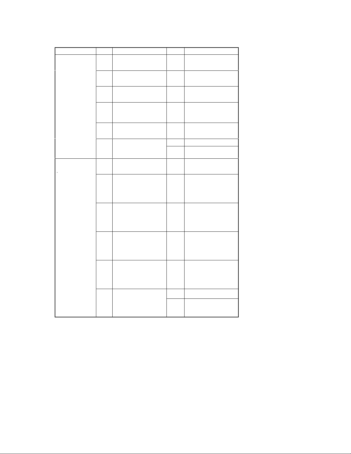
!Copier Paper Take-Up Misfeed Clearing Procedure
T
ake Up
Sensor
p
y
ly?
Symptom Step Check Item Result Action
Paper is not taken
D
up at all.
Paper is stationary
D
before the Paper
Take-Up Sensor.
Paper is stationary
at the Vertical Transport Section.
.
Does the paper being used
meet product specifica-
1
tions?
Is the paper curled, waved,
or damp?
2
Is the Trailing Edge Stop or
Edge Guide in good posi-
3
tion?
Are the Paper Take-Up Roll
and Separator Roll de-
4
formed, worn, or dirty with
paper dust?
Is the Paper Take-Up Motor
(M11, M12) turning when
5
the Start key is pressed?
Run the “Controller/Board
Check.” Is either of the
6
malfunction codes C032A
and C032B displayed?
Are the Vertical Transport
Rollers deformed, worn, or
1
dirty with paper dust?
Does PC63 operate properly?
Using the IC Port Data
2
Check function, make an input port check on PWB-A
(IC3A) APB6.
Does PC64 operate properly?
Using the IC Port Data
3
Check function, make an input port check on PWB-A
(IC3A) APB7.
Does PC56 operate properly?
Using the IC Port Data
4
Check function, make an input port check on PWB-A
(IC3A) APB3.
Does PC57 operate properly?
Using the IC Port Data
5
Check function, make an input port check on PWB-A
(IC3A) APB4.
Does PC54 operate properl
?
Using the IC Port Data
6
Check function, make an input port check on PWB-A
(IC5A) BPB6.
Instruct the user to use the
paper that meets product
NO
specifications.
Change the paper. Instruct
the user in how to store the
YES
paper.
Position the edge stop and
guide to meet the paper
NO
size.
Clean or change the Paper
Take-Up Roll and/or Sepa-
YES
rator Roll.
Check the motor for overload.
NO
Change PWB-A.
YES
Change M11, M12, or
NO
PWB-C.
Clean or change the Vertical Transport Rollers.
YES
Check the PC63 actuator
for operation and, if it
checks okay, change PC63.
NO
Check the PC64 actuator
for operation and, if it
checks okay, change PC64.
NO
Check the PC56 actuator
for operation and, if it
checks okay, change PC56.
NO
Check the PC57 actuator
for operation and, if it
checks okay, change PC57.
NO
Change PWB-A.
YES
Check the PC54 actuator
for operation and, if it
NO
checks okay, change PC54.
T-25
Page 27

Symptom Step Check Item Result Action
Paper is stationary
at the Vertical Transport Section
Does CL1 operate properly?
Using the IC Port Data
7
Check function, set the data
of PWB-A (IC4A) BPA3 to
“0.”
Run the “Controller Board
”
Check.” Is the malfunction
8
code “C0321” displayed?
Check the drive transmission path.
YES
Change PWB-A.
YES
Change CL1.
NO
T-26
Page 28
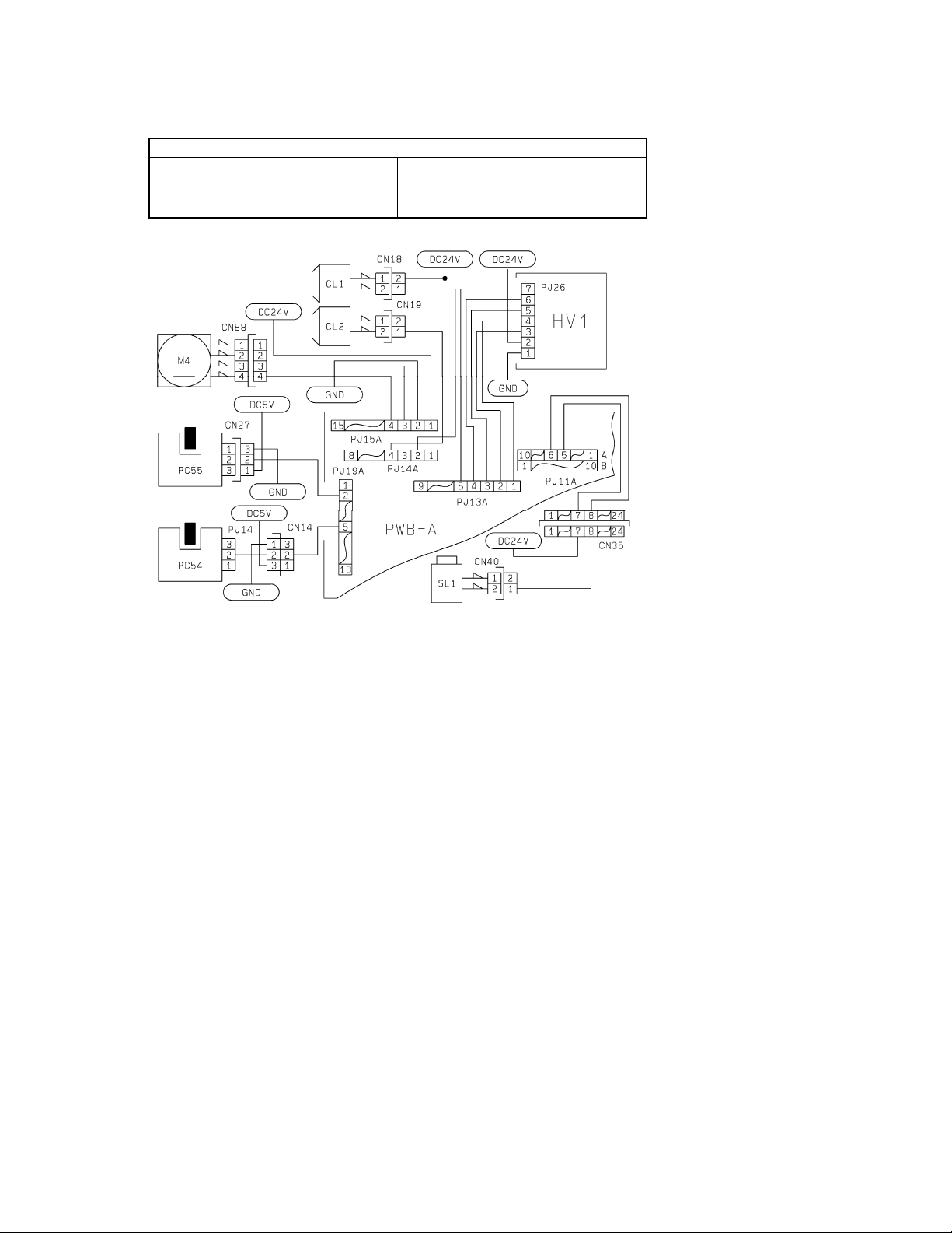
1156SBT030302A
2) Transport/Separator Misfeed
Transport Roller Sensor PC54
D
Paper Leading Edge Detecting Sensor PC55
D
Paper Transport Clutch CL1
D
Synchronizing Roller Clutch CL2
D
Relevant Electrical Parts
Separator Solenoid SL1
D
Suction Fan Motor M4
D
High Voltage Unit HV1
D
Master Board PWB-A
D
T-27
1156C02TAA
Page 29
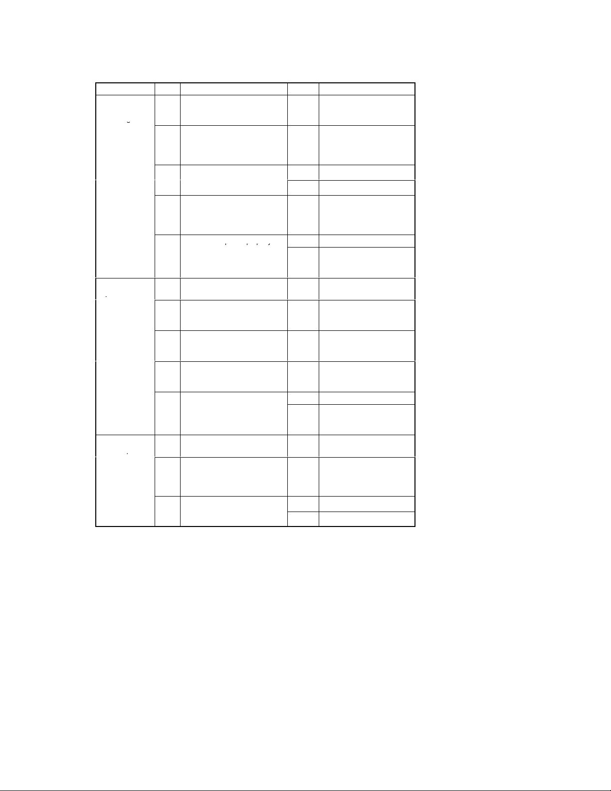
!Transport/Separator Misfeed Clearing Procedure
g
p
pp y
y
p
Symptom Step Check Item Result Action
Paper is stationary at the Synchronizing Roller.
Paper is stationary near the PC
Drum.
Paper is wedged
at the Paper
Separator Fingers.
Is the paper curled, waved or
damp?
1
Does CL2 operate properly?
Using the IC Port Data Check
2
function, set the data of PWB-A
(IC4A) BPA4 to “0.”
Run the “Controller Board
”
Check.” Is the malfunction code
3
“C0320” displayed?
Is an adequate length of loop
formed before the Synchroniz-
4
ing Roller?
Does PC55 operate properly? YES Change PWB-A.
Using the IC Port Data Check
5
function, make an input port
check on PWB-A (IC5A) BPB5.
Is the Pre-Image Transfer Guide
1
Plate deformed or dirty?
Are the Image Transfer/Paper
Separator Corona wires deterio-
2
rated or dirty?
Is the paper guide at the Paper
Separator Corona deformed or
3
dirty?
Are the Synchronizing Rollers
deformed, worn, or dirty with pa-
4
per dust?
Run the “Controller Board YES Change PWB-A.
Check.” Is the malfunction code
5
“C031D” or ”C031E” displayed?
Are the Paper Separator Fin-
1
gers deformed or dirty?
Does SL1 operate properly?
Using the IC Port Data Check
2
function, set the data of PWB-A
(IC4A) BPA0 to “0.”
Run the “Controller Board
”
Check.” Is the malfunction code
3
“C0324” displayed?
Change the paper. Instruct
the user in how to store the
YES
paper.
Check the drive transmission path.
YES
Change PWB-A.
YES
Change CL2.
NO
Adjust the loop length using
the “Loop Adjust (Drawer)”
NO
function of “Tech. Rep.
Choice.”
Check the PC55 actuator for
operation and, if it checks
NO
okay, change PC55.
Correct, clean, or change
YES
the guide plate.
Clean or change the wires.
YES
Clean or change the paper
guide.
YES
Clean or change the Synchronizing Rollers.
YES
Change the Image Transfer/
Paper Separator Coronas
NO
Assy or HV1.
Clean or change the Paper
YES
Separator Fingers.
Check the drive transmission path.
YES
Change PWB-A.
YES
Change SL1.
NO
T-28
Page 30

Symptom Step Check Item Result Action
y
Paper is stationary on the Suction Belts.
Do the Suction Belts turn when
1
the Main Drive Motor runs?
Does M4 operate properly?
Using the IC Port Data Check
function, set the data of PWB-A
2
(IC4A) BPC2 to “0.” Does M4
then run at full speed?
Check the drive gears and
NO
timing belt.
Check the Suction Belts.
YES
Change M4 or PWB-A.
NO
T-29
Page 31

1156SBT030303A
3) Multi Bypass Misfeed
Manual Feed Paper Empty Sensor PC51
D
Manual Feed Paper Take-Up Solenoid SL51
D
Manual Feed Paper Take-Up Clutch CL3
D
Relevant Electrical Parts
Master Board PWB-A
D
T-30
1156C03TAA
Page 32

!Multi Bypass Misfeed Clearing Procedure
y
tected
ly?
Symptom Step Check Item Result Action
Paper is not detected.
.
Paper is not taken
up at all.
Does PC51 operate properl
?
Using the IC Port Data
1
Check function, make an input port check on PWB-A
(IC5A) BPB1.
Does the paper being used
meet product specifica-
1
tions?
Is the paper curled, waved,
or damp?
2
Is the Manual Bypass Paper Take-Up Roll deformed,
3
worn, or dirty with paper
dust?
Does SL51 operate properly?
Using the IC Port Data
4
Check function, set the data
of PWB-A (IC5A) BPA3 to
“0.” Does the roll then go
down?
Run the “Controller/Board
”
Check.” Is the malfunction
5
code ”C0336” displayed?
Does CL3 operate properly?
Using the IC Port Data
6
Check function, set the data
of PWB-A (IC5A) BPA1 to
“0.”
Run the “Controller/Board
”
Check.” Is the malfunction
7
code “C0337” displayed?
Change PWB-A.
YES
Check the PC51 actuator
for operation and, if it
NO
checks okay, change PC51.
Instruct the user to use the
paper that meets product
NO
specifications.
Change the paper. Instruct
the user in how to store the
YES
paper.
Clean or change the Manual Bypass Paper Take-Up
YES
Roll.
Check the drive transmission path.
YES
Change PWB-A.
YES
Change SL51.
NO
Check the drive transmission path.
YES
Change PWB-A.
YES
Change CL3.
NO
T-31
Page 33

1156SBT030304A
4) Fusing/Exit Misfeed
Paper Exit Switch S53
D
Relevant Electrical Parts
Suction Fan Motor M4
D
Master Board PWB-A
D
1156C04TAA
T-32
Page 34

!Fusing/Exit Misfeed Clearing Procedure
Check
function
set
the
data
g
y
at
the
Exit
Roller
ly?
Symptom Step Check Item Result Action
Paper is stationary
before the Fusing
Roller.
Paper is stationary
at the Fusing Roller.
Paper is stationary
at the Exit Roller.
.
Is the paper curled, waved,
or damp?
1
Is the Fusing Guide Plate
2
deformed or dirty?
Does M4 operate properly?
Using the IC Port Data
Check function, set the data
3
of PWB-A (IC4A) BPC2 to
“0.” Does M4 then turn at
full speed?
Are the Fusing Rollers dirty
1
or scratched?
Are the Fusing Roller Paper
Separator Fingers de-
2
formed, worn, or dirty?
3 Is the Cleaning Roller dirty
or scratched?
Does S53 operate properl
?
Using the IC Port Data
1
Check function, make an input port check of PWB-A
(IC5A) BPB3.
,
Change the paper. Instruct
the user in how to store the
YES
paper.
Clean, correct, or change
YES
the Fusing Guide Plate.
Check the Suction Belts.
YES
Change M4 or PWB-A.
NO
Clean or change the Fusing
YES
Rollers.
Clean, correct, or change
the defective separator fin-
YES
gers.
Clean or change the Clean-
YES
ing Roller.
Change PWB-A.
YES
Check the S53 actuator for
operation and, if it checks
NO
okay, change S53.
T-33
Page 35

1156SBT030305A
5) PF-205 Paper Take-Up Misfeed
Relevant Electrical Parts
3rd Drawer Paper Take-Up Sensor PC21
D
4th Drawer Paper Take-Up Sensor PC29
D
Vertical Transport Sensor 3 PC17
D
Vertical Transport Sensor 4 PC22
D
3rd Drawer Paper Take-Up Motor M22
D
4th Drawer Paper Take-Up Motor M23
D
Vertical Transport Drive Motor M21
D
PF-205 Master Board PWB-A
D
EP5000/EP4000 Master Board PWB-A
D
T-34
1156C24TAA
Page 36

Symptom Step Check Item Result Action
S
Start
keyispressed?
D
Change
PWB A
T
ransport
Section
is
pressed?
D
Change
PWB A
g
Paper is not tak-
D
en up at all.
Paper is station-
D
ary before the
Paper Take-Up
ensor.
Paper is stationary
at the Vertical
Transport Section.
Does the paper being used
meet product specifications?
1
Is the paper curled, waved, or
damp?
2
Are the Paper Take-Up Roll and
Separator Roll deformed, worn,
4
or dirty with paper dust?
Is the Paper Take-Up Motor
(M22, M23) turning when the
Start key is pressed?
5
Is Vertical Transport Drive Motor
M21 turning when the Start key
.
is pressed?
1
Are the Vertical Transport Rollers deformed, worn, or dirty with
2
paper dust?
Does PC17 operate properly?
Using the IC Port Data Check
3
function, make an input port
check on PWB-A (200) IC1A
PC3 (metric areas) or PWB-A
(MC) IC1A PC3 (inch areas).
Does PC22 operate properly?
Using the IC Port Data Check
function, make an input port
4
check on PWB-A (200) IC1A
PC2 (metric areas) or PWB-A
(MC) IC1A PC2 (inch areas).
Does PC21 operate properly?
Using the IC Port Data Check
function, make an input port
5
check on PWB-A (200) IC1A
PE3 (metric areas) or PWB-A
(MC) IC1A PE3 (inch areas).
Does PC29 operate properly?
Using the IC Port Data Check
function, make an input port
6
check on PWB-A (200) IC1A
PB3 (metric areas) or PWB-A
(MC) IC1A PB3 (inch areas).
Instruct the user to use
the paper that meets
NO
product specifications.
Change the paper.
Instruct the user in how
YES
to store the paper.
Clean or change the Paper Take-Up Roll and/or
YES
Separator Roll.
Check the motor for
D
overload.
Change PWB-A
D
NO
NO
YES
NO
NO
NO
YES
NO
(PF-205) or
PWB-A (copier).
Change M22 or M23.
Check the motor for
D
overload.
Change PWB-A
D
(PF-205) or
PWB-A (copier).
Change M21.
Clean or change the Vertical Transport Rollers.
Check the PC17 actuator
for operation and, if it operates properly, change
PC17.
Check the PC22 actuator
for operation and, if it operates properly, change
PC22.
Check the PC21 actuator
for operation and, if it operates properly, change
PC21.
Change PWB-A (PF-205)
or PWB-A (copier).
Check the PC29 actuator
for operation and, if it operates properly, change
PC29.
T-35
Page 37

1156SBT030306A
6) PF-105 Paper Take-Up Misfeed
Relevant Electrical Parts
3rd Drawer Paper Take-Up Sensor PC21
D
Vertical Transport Sensor 3 PC17
D
Vertical Transport Sensor 4 PC22
D
3rd Drawer Paper Take-Up Motor M22
D
Vertical Transport Drive Motor M21
D
PF-105 Master Board PWB-A
D
EP5000/EP4000 Master Board PWB-A
D
T-36
1156C26TAA
Page 38

Symptom Step Check Item Result Action
g
Paper is not taken
D
up at all.
Paper is stationary
D
before the Paper
Take-Up Sensor.
Paper is stationary
at the Vertical Transport Section.
Does the paper being used
meet product specifica-
1
tions?
Is the paper curled, waved,
or damp?
2
Are the Paper Take-Up Roll
and Separator Roll de-
4
formed, worn, or dirty with
paper dust?
Is 3rd Drawer Paper TakeUp Motor M22 turning when
the Start key is pressed?
5
Is Vertical Transport Drive
Motor M21 turning when the
Start key is pressed?
1
Are the Vertical Transport
Rollers deformed, worn, or
2
dirty with paper dust?
Does PC17 operate properly?
3
Using the IC Port Data
Check function, make an input port check on PWB-A
(400) (IC1A) PC3.
Does PC22 operate properly?
Using the IC Port Data
4
Check function, make an input port check on PWB-A
(400) (IC1A) PC2.
Does PC21 operate properly?
Using the IC Port Data
Check function, make an in-
5
put port check on PWB-A
(400) (IC1A) PE3.
Instruct the user to use the
paper that meets product
NO
specifications.
Change the paper. Instruct
the user in how to store the
YES
paper.
Clean or change the Paper
Take-up Roll and/or Sepa-
YES
rator Roll.
Check the motor for over-
D
load.
Change PWB-A (PF-105)
D
NO
or PWB-A (copier).
Change M22.
Check the motor for over-
D
load.
Change PWB-A (PF-105)
D
NO
or PWB-A (copier).
Change M21.
Clean or change the Vertical Transport Rollers.
YES
Check the PC17 actuator
for operation and, if it operates properly, change
NO
PC17.
Check the PC22 actuator
for operation and, if it operates properly, change
NO
PC22.
Change PWB-A (PF-105)
or PWB-A (copier).
YES
Change M21.
Check the PC21 actuator
for operation and, if it oper-
NO
ates properly, change
PC21.
T-37
Page 39

1156SBT030307A
7) AD-9 Vertical Transport/Storage Misfeed
Relevant Electrical Parts
Vertical Transport Sensor 3 PC17
D
Duplex Unit Vertical Transport Sensor PC12
D
Duplex Unit Turnover Path Sensor PC13
D
Duplex Unit Paper Entry Sensor PC14
D
Duplex Unit Paper Empty Sensor PC15
D
Vertical Transport Sensor 3 PC17
D
D
D
D
D
D
D
Exit/Duplex Switching Solenoid SL5
Duplex Unit Gate Switching Solenoid SL31
Duplex Unit Drive Motor M31
Duplex Unit Master Board PWB-G
PF-205/105 Master Board PWB-A
EP5000/EP4000 Master Board PWB-A
T-38
1156C30TAA
Page 40

!AD-9 Vertical Transport Misfeed Clearing Procedure
y
Symptom Step Check Item Result Action
Paper is stationary
at the copier exit
section.
Paper is stationary
at the Duplex Unit
Vertical Transport
Section.
Paper is stationary
at the Duplex Unit
Turnover Section.
Does SL5 operate properly?
Using the IC Port Data
1
Check function, set the data
of PWB-A (IC4A) BPA5 to
“0.”
Run the “Controller Board
”
Check.” Is the malfunction
2
code “C0324” displayed?
Do the Vertical Transport
Roller and drive coupling
operate properly when M31
is running?
1
Using the IC Port Data
Check function, set the data
of PWB-G (Dup) (IC1G)
PB3 to “0.”
Does PC12 operate properly?
Using the IC Port Data
2
Check function, make an input port check of PWB-A
(IC5A) BPB0.
Do the Paddle Roller, Slip
Roller, and drive coupling
operate properly when M31
is running?
1
Using the IC Port Data
Check function, set the data
of PWB-G (Dup) (IC1G)
PB3 to “0.”
Does PC13 operate properly?
Using the IC Port Data
2
Check function, make an input port check of PWB-A
(200/400) (IC2A) PB0.
Check the drive transmission path.
YES
Change PWB-A.
YES
Change SL51.
NO
Check the gears, belts, and
rollers.
NO
Change PWB-A.
YES
Check the PC12 actuator
for operation and, if it oper-
NO
ates properly, change
PC12.
Check the gears, belts, and
rollers.
NO
Change PWB-A (copier) or
YES
PWB-A (PF-205/105).
Check the PC13 actuator
for operation and, if it oper-
NO
ates properly, change
PC13.
T-39
Page 41

!AD-9 Storage Misfeed Clearing Procedure
pp
,
y
g
Symptom Step Check Item Result Action
The leading edge of
the paper is stationary inside the Duplex Unit.
Paper is stationary
at the storage section.
Is the Paper Guide Mylar
1
dirty or deformed?
Does PC14 operate properly? Using the IC Port Data
Check function, make an input port check on PWB-A
2
(Dup) (IC1G) PC1.
Does SL31 operate properly?
Using the IC Port Data
3
Check function, set the data
of PWB-A (Dup) (IC1G)
PH1 to “0.”
Does PC15 operate properly?
Using the IC Port Data
Check function, make an in-
1
put port check of PWB-A
(Dup) (IC1G) C2.
Clean or change the mylar.
YES
Change PWB-G, PWB-A
(copier), or PWB-A
YES
(PF-205/105).
Check the PC14 actuator
for operation and, if it oper-
NO
ates properly, change
PC14.
Check the Gate Switching
YES
Lever for operation.
Change PWB-G, PWB-A
(copier), or PWB-A
NO
(PF-205/105). Change
SL31.
Change PWB-G, PWB-A
(copier), or PWB-A
YES
(PF-205/105).
Check the PC15 actuator
for operation and, if it oper-
NO
ates properly, change
PC15.
T-40
Page 42

1156SBT030308A
8) AD-9 Paper Take-Up Misfeed
Relevant Electrical Parts
Duplex Unit Paper Take-Up Sensor PC16
D
Vertical Transport Sensor 3 PC17
D
Vertical Transport Drive Motor M21
D
Duplex Unit Paper Take-Up Clutch CL31
D
Duplex Unit Pick-Up Solenoid SL33
D
Duplex Unit Master Board PWB-G
D
PF-205/105 Master Board PWB-A
D
EP5000/EP4000 Master Board PWB-A
D
T-41
1156C31TAA
Page 43

!AD-9 Paper Take-Up Misfeed Clearing Procedure
p1y
y
g
y
y
Symptom Step Check Item Result Action
Paper is not taken
up at all.
Paper is stationary
at the Vertical Transport Section.
Does SL33 operate properly?
Using the IC Port Data
Check function, set the data
of PWB-A (Dup) (IC1G)
PB2 to “0.”
Does CL33 operate properly?
Using the IC Port Data
2
Check function, set the data
of PWB-A (Dup) (IC1G)
PA3 to “0.”
Are the Take-Up Roll, Feed
Roll, and Separator Roll de-
3
formed, worn, or dirty with
paper dust?
Is Vertical Transport Drive
Motor M21 turning when a
copy is taken up and fed
1
into the copier from the Duplex Unit?
Are the Vertical Transport
Rollers deformed, worn, or
2
dirty with paper dust?
Does PC17 operate properly?
Using the IC Port Data
3
Check function, make an input port check of PWB-A
(200, 400) (IC1A) PC3.
Does PC16 operate properly?
Using the IC Port Data
4
Check function, make an input port check of PWB-A
(Dup) (IC1G) PC0.
Check the pick-up mecha-
YES
nism.
Change PWB-G, PWB-A
(copier), or PWB-A
NO
(PF-205/105). Change
SL33.
Check the drive transmis-
YES
sion path.
Change PWB-G, PWB-A
(copier), or PWB-A
NO
(PF-205/105). Change
CL31.
Clean or change the defective roll.
YES
Check the motor for over-
YES
load.
Change PWB-A (copier) or
PWB-A (PF-205/105).
NO
Change M21.
Clean or change the defective roller.
YES
Change PWB-A (copier) or
YES
PWB-A (PF-205/105).
Check the PC17 actuator
for operation and, if it oper-
NO
ates properly, change
PC17.
Change PWB-A (copier) or
YES
PWB-A (PF-205/105).
Check the PC16 actuator
for operation and, if it oper-
NO
ates properly, change
PC16.
T-42
Page 44

1151SBT0400A
MALFUNCTIONS4
1156SBT0401A
4-1. Detection Timings Classified by Malfunction Codes
The codes marked with an asterisk (*) are the candidates for isolated malfunctions.
D
C00## Drive Malfunctions
* Code Description Detection Timing
Main Drive Motor M1’s failure to turn The lock signal remains HIGH for a continu-
C0000
Main Drive Motor M1 turning at abnormal timing
C0001
Suction Fan Motor M4’s failure to turn The lock signal remains HIGH for a continu-
C0040
Fusing Section Cooling Fan Motor
M15’s failure to turn
C0046
Fusing Section Cooling Fan Motor
* C0047
* C004b
* C004d
M15 turning at abnormal timing
Original Glass Cooling Fan Motor
M5’s failure to turn
C004A
Original Glass Cooling Fan Motor M5
turning at abnormal timing
Ventilation Fan Motor M3’s failure to
turn
C004c
Ventilation Fan Motor M3 turning at
abnormal timing
Main Hopper Toner Replenishing Motor M8’s failure to turn
C0070
Main Hopper Toner Replenishing Mo-
C0071
tor M8 turning at abnormal timing
Sub Hopper Toner Replenishing Motor
M9’s failure to turn
C0072
1156SBT040101A
ous 2.0-sec. or more period while M1 is energized.
The lock signal remains LOW for a continuous 1.5-sec. or more period while M1 is deenergized.
ous 1.0-sec. or more period while M4 is energized.
The lock signal remains HIGH for a continuous 2.0-sec. or more period while M15 is energized.
The lock signal remains LOW for a continuous 2.0-sec. or more period while M15 is
deenergized.
The lock signal remains HIGH for a continuous 2.0-sec. or more period while M5 is energized.
The lock signal remains LOW for a continuous 2.0-sec. or more period while M5 is deenergized.
The lock signal remains HIGH for a continuous 2.0-sec. or more period while M3 is energized.
The lock signal remains LOW for a continuous 2.0-sec. or more period while M3 is deenergized.
Toner Bottle Home Position Sensor PC35
D
does not go from HIGH to LOW within 12 sec.
after M8 has been energized.
PC35 does not go LOW within 12 sec. after
D
M8 has been energized and PC35 gone
HIGH.
PC35 is HIGH 2 sec. after M8 has been deenergized.
When the current toner-to-carrier ratio is 2%
lower than the SCH-90 setting and the Add
Toner Indicator is not lit on the control panel, a
toner replenishing sequence is carried out
(M9 is turned); the toner-to-carrier ratio does
not increase by 1% within 140 seconds or by
2% within 220 seconds.
T-43
Page 45

C02## Corona Malfunction
* Code Description Detection Timing
PC Drum Charge, Image Transfer, Paper Separator Corona malfunction
C0200
1156SBT040102A
The leak signal (SCD) turns ON after the PC
Drum Charge and Image Transfer/Paper Separator Corona output has been turned ON.
C03## Master Board/Harness Malfunctions
The copier performs a self-diagnostic sequence to determine if the microprocessor outputs a signal to
D
each of the IC ports on Master Board PWB-A properly. It is intended for detecting the following malfunctions (C03##).
Any malfunction is detected when “Controller Board Check” available from the “I/O Check” function of the
D
Tech. Rep. mode is executed.
If the microprocessor fails to output any of these signals or if any of the electronic components on the board
D
(driver IC, etc.) is faulty,the copier determines that there is a faulty condition existing and shows the corresponding malfunction code on the Touch Panel.
C0350, C0351, C0352, C0353, or C0357 is displayed when there is a communication fault between the
D
copier and paper feeder option or Duplex Unit, and detected as an isolated malfunction when the Power
Switch is turned ON.
Code Description Master Board Port
*
C0300 Port diagnosis cannot be started. —
C0310 Drum Dehumidifying Heater H2 REM signal IC1A P45
C0311 Fusing Heater Lamp H1 REM signal IC1A P57
C0312 Exposure Lamp Regulator PWB-J REM signal IC1A P61
C0313 AE Sensor Board PWB-H PWM signal IC1A P60
C0314 Image Erase Lamp LA3 DATA IC1A P64
C0315 Image Erase Lamp LA3 MODE IC1A P65
C0316 Image Erase Lamp LA3 CLOCK IC1A P66
C0317 Image Erase Lamp LA3 STROBE IC1A P67
C0318 Copy vendor count (during copy cycle) IC3A APA1
C0319 Copy vendor count (size) IC3A APA0
C031A 2nd Drawer Paper Take-Up Motor M12 energization IC3Aφ1
C031B 1st Drawer Paper Take-Up Motor M11 energization IC3AφO
C031C Original size detection IC4A APA7
C031D Original size detection, marketing area 2 IC4A APA6
C031E Original size detection, marketing area 1 IC4A APA5
C031F Scanner Motor M2 SCAN signal IC4A APC0
C0320 Scanner Motor M2 ENABLE signal IC4A APC1
C0321 Fusing Section Cooling Fan Motor M15 REM signal IC4A APC2
C0322 Separator/Developing Bias output REM signal IC4A BPA7
C0323 PC Drum Charge/Image Transfer output REM signal IC4A BPA6
C0324 Exit/Duplex Switching Solenoid SL5 IC4A BPA5
C0325 Synchronizing Roller Clutch CL2 IC4A BPA4
C0326 Paper Transport Clutch CL1 IC4A BPA3
C0327 Main Drive Motor M1 REM signal IC4A BPA2
C0328 Main Erase Lamp LA2 REM signal IC4A BPA1
C0329 Separator Solenoid SL1 REM signal IC4A BPA0
1156SBT040103A
T-44
Page 46

* Code Description Master Board Port
g
py
/
C032A Main Hopper Toner Replenishing Motor M8 IC4A BPC3
C032B Suction Fan Motor M4 33/ Ventilation Fan Motor M3 IC4A BPC2
C032C Ventilation Fan Motor M3 IC4A BPC1
C032D 2nd Drawer Paper Lift-Up Motor M14 DOWN IC5A APA7
C032E 2nd Drawer Paper Lift-Up Motor M14 UP IC5A APA6
C032F 1st Drawer Paper Lift-Up Motor M13 DOWN IC5A APA5
C0330 1st Drawer Paper Lift-Up Motor M13 UP IC5A APA4
C0331 Separator bias switching IC5A APA3
C0332 Sub Hopper Toner Replenishing Motor M9 IC5A APA2
C0333 2nd Drawer Paper Take-Up Motor M12 ENABLE IC5A APA1
C0334 1st Drawer Paper Take-Up Motor M11 ENABLE IC5A APA0
C0335 Manual Feed Paper Take-Up Solenoid SL4 UP IC5A BPA2
C0336 Manual Feed Paper Take-Up Solenoid SL4 DOWN IC5A BPA3
C0337 Manual Feed Paper Take-Up Clutch CL3 IC5A BPA1
C0338 Warming-up completion signal IC5A BPA7
C0339 During copy cycle IC5A BPA6
C033A SSR2 REM signal (MH only) IC5A BPA5
C033B Exposure Lamp Regulator PWB-J PWM signal IC4A TOUT
C033C Grid PWM signal IC5A TOUT
C0350 Paper Feed Cabinet S/P-0 IC3 SO0
C0351 Paper Feed Cabinet S/P-1 IC3 SO1
C0352 Duplex Unit S/P-2 IC3 SO2
C0353 Large Capacity Cassette S/P-3 IC3 SO3
C0357
IC3 S13
T-45
Page 47

1156SBT040104A
C04## Exposure Lamp Malfunctions
* Code Description Detection Timing
C0400 Exposure Lamp LA1’s failure to turnONThe output from AE Sensor Board PWB-H
C0410 Exposure Lamp LA1 turning ON at ab-
normal timing
1156SBT040105A
does not become 4.0V or more for the period
between when LA1 turns ON and the Scanner
starts a scan motion and when the Image
Leading Edge signal (BASE) turns ON.
With LA1 OFF, the output from PWB-H remains 3.9V or less for a continuous 3-sec.
period at any timing while the Scanner is at
the home position or the Original Cover is
lowered.
C05## Fusing Malfunctions
* Code Description Detection Timing
C0500 Warming-up failure
(Fusing Heater Lamp failure)
C0510 Abnormally low fusing temperature
(Fusing Heater Lamp failure)
C0520 Abnormally high fusing temperature
(Fusing Heater Lamp turning ON at
abnormal timing)
The surface temperature of the Upper Fusing
Roller does not reach a given level even after the
lapse of a given period of time during warming-up
as detailed below:
If the temperature is 165_C or less when the Pow-
D
er Switch is turned ON:
EP4051 EP3051
From room temperature 105S 60S
to 65_C
65_C~140_C 210S 110S
140_C~170_C 220S 120S
*170_C~200_C 145S 100S
*170_C~190_C 145S 100S
If the temperature is more than 165_C when the
D
Power Switch is turned ON:
*~200_C 200S 120S
*~190_C 200S 120S
*A 200_C temperature control is provided for the
first 1 hour after the Power Switch has been
turned ON and 190_C temperature control is
provided thereafter.
The surface temperature of the Upper Fusing
Roller remains 135
5-sec. period or more after the copier has completed warming up.
The surface temperature of the Upper Fusing
Roller remains 230
5-sec. period or more after the copier has completed warming up.
°°°°
°°°°
EP4051 EP3051
C or less for a continuous
C or more for a continuous
T-46
Page 48

1156SBT040106A
C06## Optical Malfunctions
* Code Description Detection Timing
C0600 Scanner Motor M2 malfunction
C0610 Lens Motor M6 malfunction The output from Lens Reference Position Sensor
C0620 Mirror Motor M7 malfunction
C06F0 SHOME signal failure (Signal does
not go LOW)
C06F1 SHOME signal failure (Signal does
not go HIGH)
C06F2 BASE signal failure (Signal does
not go LOW)
C06F3 BASE signal failure (Signal does
not go HIGH)
C06F4 TRON signal failure (Signal does
not go LOW)
C06F5 TRON signal failure (Signal does
not go HIGH)
C06F6 SCEND signal failure (Signal does
not go LOW)
C06F7 SCEND signal failure (Signal does
not go HIGH)
When the Scanner is at a position other than
D
home, Scanner Reference Position Sensor
PC81 does not go from HIGH to LOW even after
the lapse of 20 sec. after the Power Switch has
been turned ON.
When the Scanner is at the home position, PC81
D
does not go from LOW to HIGH even after the
lapse of 5 sec. after the Scanner has started a
scan motion.
PC81 does not go from HIGH to LOW even after
D
the lapse of 20 sec. after the Scanner has started
a scan motion.
PC90 does not go from HIGH to LOW, or vice
versa, even after the lapse of 15 sec. after M6
has started turning.
The output from Mirror Reference Position Sen-
D
sor PC86 does not go from HIGH to LOW even
after the lapse of 10 sec. after M7 has started
turning.
The output from PC86 does not go from LOW to
D
HIGH even after the lapse of 3 sec. after M7 has
started turning.
When the Scanner is at a position other than
D
home, the SHOME signal does not go HIGH
even after the lapse of 7 sec. after the SCAN signal has gone LOW.
The SHOME signal is HIGH even after the lapse
D
of 5 sec. after the BASE signal has gone from
LOW to HIGH.
The SHOME signal remains LOW even after the
lapse of 7 sec. after it has gone LOW.
The BASE signal does not go LOW even after
the lapse of 5 sec. after the SHOME signal has
gone HIGH.
The BASE signal remains LOW even after the
lapse of 5 sec. after the SHOME signal has gone
HIGH.
The TRON signal remains HIGH even after the
lapse of 5 sec. after the BASE signal has gone
LOW.
The TRON signal remains LOW even after the
lapse of 5 sec. after it has gone LOW.
The SCEND signal remains HIGH even after the
lapse of 5 sec. after the TRON signal has gone
LOW.
The SCEND signal remains LOW even after the
lapse of 5 sec. after it has gone LOW.
T-47
Page 49

1156SBT040107A
C09## Paper Take-Up Malfunctions
* Code Description Detection Timing
C0900 3rd Drawer upward motion failure
C0901
(Inch Area)
C0902
(Inch Area)
C0903
(Inch Area)
C0904
C0906
(Inch Area)
*
C0950 4th Drawer upward motion failure
C0951
(Inch Area)
C0952
(Inch Area)
C0953
(Inch Area)
C0954
C0956
(Inch Area)
3rd Drawer downward motion failure
3rd Drawer downward motion failure
3rd Drawer upward motion failure
3rd Drawer Lift-Up Motor M24’s failure to turn
3rd Drawer ejection failure
See PF-205 Service Manual.
4th Drawer downward motion failure
4th Drawer downward motion failure
4th Drawer upward motion failure
4th Drawer Lift-Up Motor M25’s failure to turn
4th Drawer ejection failure
T-48
Page 50

* Code Description Detection Timing
*
*
2nd Drawer upward motion failure
C0910
2nd Drawer downward motion failure
C0911
2nd Drawer downward motion failure
C0912
2nd Drawer upward motion failure
C0913
2nd Drawer Paper Lift−Up Motor
M14’s failure to turn
C0914
2nd Drawer ejection failure
C0916
1st Drawer upward motion failure
C0920
1st Drawer downward motion failure
C0921
2nd Drawer Lift-Up Sensor PC66 is not blocked
D
(L) even after the lapse of 5 sec. after 2nd Drawer
Paper Lift-Up Motor M14 has been energized.
PC66 is not blocked (L) even if 2nd Drawer Lift-
D
Up Motor Pulse Sensor PC68 detects 75 pulses
after M14 has been energized.
When PC66 is blocked (L), it is not unblocked (H)
D
even after the lapse of 5 sec. after M14 has been
energized.
PC66 is not unblocked (H) even if PC68 detects
D
10 pulses after M14 has been energized.
When PC66 is unblocked (H), 2nd Drawer Lower
D
Limit Position Sensor PC70 is not blocked (L)
even after the lapse of 5 sec. after M14 has been
energized.
PC70 is not unblocked (H) even after the lapse
D
of 1.5 sec. after it has been blocked (L).
PC70 is not blocked (L) even if PC68 detects 75
D
pulses after M14 has been energized.
PC70 is not blocked (L) even after the lapse of 2
D
sec. after M14 has been energized.
When PC70 is blocked (L), it is not unblocked (H)
D
even after the lapse of 5 sec. after M14 has been
energized.
PC70 is not unblocked (H) even after the lapse
D
of 2 sec. after it has been blocked (L).
PC68 detects no pulses even after the lapse of
D
500 msec. after M14 has been energized.
PC68 detects no pulses for the period of 200
D
msec. while M14 is being energized.
The 2nd Drawer is not ejected even after the
D
lapse of 2 sec. after PC70 has been blocked (L).
1st Drawer Lift-Up Sensor PC65 is not blocked
D
(L) even after the lapse of 5 sec. after 1st Drawer
Paper Lift-Up Motor M13 has been energized.
PC65 is not blocked (L) even if 1st Drawer Lift-
D
Up Motor Pulse Sensor PC67 detects 75 pulses
after M13 has been energized.
When PC65 is blocked (L), it is not unblocked
D
(H) even after the lapse of 5 sec. after M13 has
been energized.
PC65 is not unblocked (H) even if PC67 detects
D
10 pulses after M13 has been energized.
1st Drawer downward motion failure
C0922
1st Drawer upward motion failure
C0923
When PC65 is unblocked (H), 1st Drawer Lower
D
Limit Position Sensor PC69 is not blocked (L)
even after the lapse of 5 sec. after M13 has been
energized.
PC69 is not unblocked (H) even after the lapse
D
of 1.5 sec. after it has been blocked (L).
PC69 is not blocked (L) even if PC67 detects 75
D
pulses after M13 has been energized.
PC69 is not blocked (L) even after the lapse of 2
D
sec. after M13 has been energized.
When PC69 is blocked (L), it is not unblocked (H)
D
even after the lapse of 5 sec. after M13 has been
energized.
PC69 is not unblocked (H) even after the lapse
D
of 2 sec. after it has been blocked (L).
T-49
Page 51

* Code Description Detection Timing
*
1st Drawer Paper Lift−Up Motor
M13’s failure to turn
C0924
1st Drawer ejection failure
C0926
PC67 detects no pulses even after the lapse of
D
500 msec. after M13 has been energized.
PC67 detects no pulses for the period of 200
D
msec. while M13 is being energized.
The 1st Drawer is not ejected even after the
D
lapse of 2 sec. after PC69 has been blocked (L).
T-50
Page 52

* Code Description Detection Timing
C0990 Main Tray upward motion failure
C0991 Main Tray downward motion failure
C0992 Main Tray downward motion failure
C0993 Main Tray upward motion failure
C0994 Elevator Motor M26’s failure to turn
C0996 Main Tray ejection failure
C0998 Shifter transfer failure See PF-105 Service Manual.
* C0999 Shifter return failure
C099A Shifter return failure
C099b Shifter transfer failure
C099C Shift Motor M27’s failure to turn
C099E Shift Gate position detecting failure
C099F Shift Gate position detecting failure
C09C0 Elevator ascent fault See C-301 Service Manual.
C09C2 Elevator descent fault
T-51
Page 53

1156SBT040108A
C0E## Erase Lamp Malfunctions
* Code Description Detection Timing
C0E00
C0E01
C0E20
1156SBT040109A
Main Erase Lamp LA2’s failure to
turn ON
Main Erase Lamp LA2 turning ON
at abnormal timing
Image Erase Lamp LA3’s failure to
turn ON
The LA2 Failure Detection signal remains HIGH
for a continuous 1-sec. period while LA2 is ON.
The LA2 Failure Detection signal remains LOW
for a continuous 1-sec. period while LA2 is OFF.
The LA3 gate array is faulty as found through a
self-diagnostic sequence carried out immediately
after Main Drive Motor M1 has been deenergized.
C0F## Sensor Malfunctions
* Code Description Detection Timing
* C0F02
C0F10
* C0F20
* C0F22
* C0F23
Original Size Detecting Board UN2
malfunction
AE Sensor Board PWB-H malfunction
AIDC Sensor Board PWB-G variation correction failure
AIDC Sensor Board PWB-G grid
voltage (Vg) correction failure
AIDC Sensor Board PWB-G exposure correction failure
Undefined data is input to the master CPU.
D
Under normal conditions:
D
A fixed-cycle pulse signal (Busy) remains HIGH
or LOW for 3 sec. or more.
When the Power Switch is ON:
D
A fixed-cycle pulse signal (Busy) remains HIGH
or LOW for 5 sec. or more.
The output from PWB-H remains approx. 0.18V
or less for a continuous 2-sec. period, with the
Exposure Lamp OFF, the Scanner at the home
position, and the Original Cover lowered.
In the initial F5 or FF mode:
The output from PWB-G is 1V or more when the
D
load resistance is made maximum by the 4-bit
analog switch.
The output from PWB-G is less than 1V when the
D
load resistance is made minimum by the 4-bit
analog switch.
The output from PWB-G does not fall within the
D
0.9V-1.1V range when the intensity of PWB-G
LED is varied.
In the initial F5 or FF mode:
1) Vg of 580V is output.
2) A solid black pattern is produced and the
PWB-G output is sampled.
3) If the average is less than 4.3V, Vg is increased.
In the initial F5 or FF mode:
1) The Exposure Lamp is turned ON with
58V.
2) A halftone pattern is produced and the
PWB-G output is sampled.
3) If the average does not fall within the target range, the exposure level is varied.
4) The average does not fall within the target
range even after steps 1) to 3) have been repeated 15 times.
T-52
Page 54

* Code Description Detection Timing
*
ATDC Sensor UN3 adjustment fail-
C0F30
ure
ATDC Sensor UN3 failure
C0F31
3rd Drawer Paper Empty Sensor
D
PC20 failure
Main Tray Paper Empty Board
D
C0F79
PWB-E failure
Shift Tray Paper Empty Sensor
D
PC1 failure
Paper Empty Sensor EMPSEN fail-
D
ure
The UN3 output does not fall within the target
range in the F8 mode.
The “ATDC Ref. Value” of “Level History” drasti-
D
cally deviates from the value set in the FF mode.
The UN3 output remains 0.5V or less or 4.2V or
D
more for a consecutive 3-sec. period 2 sec. after
Main Drive Motor M1 has been energized.
See the PF-105 Service Manual.
See the C-301 Service Manual.
T-53
Page 55

Code Description Sensor Layout
!
:
PC1
16,":
PC1
17,#:
PC118(option),
d
n
A
n
(op
)
#
:
PC118(option)
$
:
PC1
15
%
:
PC119(option)
!
BCD
E
B
C0FE1
C0FE2
C0FE3
C0FE4
C0FE5
C0FE6
d*
C0FE7
ng Boar
C0FE8
Detecti
C0FE9
inal Size
Origi
C0FEA
C0FEB
C0FEC
C0FED
C0FEE
C0FEF
Original Size Detecting
Sensor
Original Size Detecting
Sensor
Original Size Detecting
Sensors
Original Size Detecting
Sensor
Original Size Detecting
Sensors
Original Size Detecting
Sensors
Original Size Detecting
Sensors
Original Size Detecting
Sensor
Original Size Detecting
Sensors
Original Size Detecting
Sensors
Original Size Detecting
Sensors
Original Size Detecting
Sensors
Original Size Detecting
Sensors
Original Size Detecting
Sensors
Original Size Detecting
Sensors
failure
!
failure
"
and"failure
!
failure
#
and#failure
!
, and#failure
"
, and#failure
!,"
failure
$
and$failure
!
and$failure
"
, and$failure
!,"
and$failure
#
, and$failure
!,#
, and$failure
",#
!,",#
, and$failure
<Detection Timing>
After having read the output data from PC115 to
PC119, UN2 determines that there is a failure.
<Sensor Layout>
Metric Areas
: PC116,": PC117,#: PC118 (option),
D
!
: PC115,%: PC119 (option)
$
A to E: Sensor locations
D
!
A
B
B
$
%
Inch Areas
: PC116 (option),": PC117,
D
!
: PC118
#
tion),$: PC115,%: PC119(option
,
!
A
B
A
$
%
"
CD E
,
"
CD E
#
#
T-54
Page 56

Code Description Sensor Layout
%
gB
t
Inch
A
g
S
(p )
(p )
!
BCD
E
C0FF0
C0FF1
C0FF2
C0FF3
C0FF4
C0FF5
C0FF6
Board *
C0FF7
tectin
C0FF8
Size De
inal
C0FF9
ri
O
C0FFA
C0FFB
C0FFC
C0FFD
C0FFE
C0FFF
Original Size Detecting
Sensor
Original Size Detecting
Sensors
Original Size Detecting
Sensors
Original Size Detecting
Sensors
Original Size Detecting
Sensors
Original Size Detecting
Sensors
Original Size Detecting
Sensors
Original Size Detecting
Sensors
Original Size Detecting
Sensors
Original Size Detecting
Sensors
Original Size Detecting
Sensors
Original Size Detecting
Sensors
Original Size Detecting
Sensors
Original Size Detecting
Sensors
Original Size Detecting
Sensors
Original Size Detecting
Sensors
failure (Metric Areas)
failure
%
and%failure
!
and%failure
"
, and%failure
!,"
and%failure
#
, and%failure
!,#
, and%failure
",#
!,",#
and%failure
$
, and%failure
!,$
, and%failure
",$
!,",$
, and%failure
#,$
!,#,$
",#,$
!,",#,$
, and%failure
, and%failure
, and%failure
, and%failure
, and
%
Metric Areas
: PC116,": PC117,#: PC118 (option),
D
!
: PC115,%: PC119 (option)
$
A to E: Sensor locations
D
!
A
B
A
B
$
reas
: PC116 (option),": PC117,
D
!
: PC118 (option),$: PC115,%: PC119 (option)
#
!
A
B
A
B
$
%
"
CD E
"
CD E
#
#
T-55
Page 57

1156SBT040110A
p
/
pp/,
/
/
p
gg
/,
/
pg
/,
/
pg
/
C0b## Staple Sorter/Sorter Malfunctions
* Code Description Detection Timing
C0b00 Transport drive malfunction See the ST-210/S-207 Service Manual.
C0b01
C0b10 Paper Clamp Unit motion failure See the ST-210/S-207, ST-101/S-104 Ser-
C0b11
C0b12 See the ST-210/S-207 Service Manual.
C0b13
C0b30 Paper Aligning Mechanism drive failure See the ST-210/S-207, ST-101/S-104 Ser-
C0b31
C0b50 Stapling failure
C0b51
C0b52
C0b53
C0b60 Bin motion failure See the ST-210/S-207, ST-101/S-104 Ser-
C0b61
*
C0b62
C0b63
C0b64
C0b65
C0b70 Hole punching failure See the ST-210/S-207 Service Manual.
C0b71
C0b72
vice Manual.
vice Manual.
vice Manual.
1156SBT040111A
C0d## Duplex Unit Malfunctions
* Code Description Detection Timing
Front/Rear Edge Guide Plates home
C0d00
position detection failure
C0d20 Gate Unit home position detection failure
Duplex Unit Drive Motor M31’s failure to
C0d50
turn
Duplex Unit Drive Motor M31 turning at
C0d51
abnormal timing
See the AD-5 Service Manual.
T-56
Page 58

1156SBT0402A
4-2. Troubleshooting Procedures
1156SBT040201A
1) C0000: Main Drive Motor M1’s Failure to Turn
C0001: Main Drive Motor M1 Turning at Abnormal Timing
Relevant Electrical Parts
Main Drive Motor M1
D
Master Board PWB-A
D
T-57
1156C05TAA
Page 59

!C0000
Step Check Item Result Action
Does M1 turn?
Set the data of PWB-A (IC4A) BPA2 to
1
“0.”
Perform the “Controller Board Check.” YES Change PWB-A.
Is malfunction code “C0327” dis-
2
played?
YES
NO
Change PWB-A.
Check the drive coupling.
D
Change M1.
D
!C0001
Step Check Item Result Action
Does M1 turn when the malfunction is
1
reset?
Is malfunction code “C0001” displayed
2
again?
YES
YES
Change PWB-A.
Change PWB-A.
T-58
Page 60

1156SBT040202A
2) C0040: Suction Fan Motor M4’s Failure to Turn
Relevant Electrical Parts
Suction Fan Motor M4
D
Master Board PWB-A
D
T-59
1156C06TAA
Page 61

!C0040
Step Check Item Result Action
Does M4 turn?
Set the data of PWB-A (IC4A) BPC2 to
1
“0.”
Perform the “Controller Board Check.”
Is malfunction code “C032B” dis-
2
played?
“
”
YES
YES
NO
Change PWB-A.
Change PWB-A.
Change M4.
D
!C0011
Step Check Item Result Action
Does M4 turn when the malfunction is
1
reset?
Is malfunction code “C0011” displayed
2
again?
YES
YES
Change PWB-A.
Change PWB-A.
T-60
Page 62

1156SBT040203A
3) C0046: Fusing Section Cooling Fan Motor M15’s Failure to Turn
C0047: Fusing Section Cooling Fan Motor M15 Turning at Abnormal Timing
Relevant Electrical Parts
Fusing Section Cooling Fan Motor M15
D
Master Board PWB-A
D
T-61
1156C07TAA
Page 63

!C0046
Step Check Item Result Action
Does M15 turn?
Set the data of PWB-A (IC4A) APC2 to
1
“0.”
Perform the “Controller Board Check.”
Is malfunction code “C0321” dis-
2
played?
“
”
YES
YES
NO
Change PWB-A.
Change PWB-A.
Change M15.
D
!C0047
Step Check Item Result Action
Does M15 turn when the malfunction is
1
reset?
Is malfunction code “C0047” displayed
2
again?
Change PWB-A or M15
YES
Change PWB-A or M15
YES
T-62
Page 64

1156SBT040204A
4) C004A: Original Glass Cooling Fan Motor M5’s Failure to Turn
C004b: Original Glass Cooling Fan Motor M5 Turning at Abnormal Timing
C004C: Ventilation Fan Motor M3’s Failure to Turn
C004d: Ventilation Fan Motor M3 Turning at Abnormal Timing
Relevant Electrical Parts
Original Glass Cooling Fan Motor M5
D
Ventilation Fan Motor M3
D
Master Board PWB-A
D
T-63
1156C08TAA
Page 65

!C004A
Step Check Item Result Action
Does M5 turn?
Set the data of PWB-A (IC4A) BPC0 to
1
“0.”
YES
NO
Change PWB-A.
Change M5.
!C004b
Step Check Item Result Action
Does M5 turn when the malfunction is
1
reset?
Is malfunction code “C004b” displayed
2
again?
YES
YES
Change PWB-A.
Change PWB-A.
!C004C
Step Check Item Result Action
Does M3 turn?
Set the data of PWB-A (IC4A) BPC1 to
1
“0.”
YES
NO
Change PWB-A.
Change M3.
!C004d
Step Check Item Result Action
Does M3 turn when the malfunction is
1
reset?
Is malfunction code “C004d” displayed
2
again?
YES
YES
Change PWB-A.
Change PWB-A.
T-64
Page 66

1156SBT040205A
5) C0070: Main Hopper Toner Replenishing Motor M8’s Failure to Turn
C0071: Main Hopper Toner Replenishing Motor M8 Turning at Abnormal Timing
C0072: Sub Hopper Toner Replenishing Motor M9’s Failure to Turn
Relevant Electrical Parts
Main Hopper Toner Replenishing Motor M8
D
Sub Hopper Toner Replenishing Motor M9
D
Toner Bottle Home Position Sensor PC35
D
Master Board PWB-A
D
T-65
1156C09TAA
Page 67

!C0070
Step Check Item Result Action
Turn the Toner Bottle a half turn by
hand and close the Front Door. Does
1
the Toner Bottle turn at this time?
Does PC35 operate properly?
Make an input port check on PWB-A
2
(IC4A) BPC5.
Perform the “Controller Board Check.”
Is malfunction code “C032A” dis-
3
played?
“
”
NO
NO
YES
NO
Go to step 3.
Change PC35.
Change PWB-A.
Change M8.
!C0071
Step Check Item Result Action
Does M8 turn when the malfunction is
1
reset?
Is malfunction code “C0071” displayed
2
again?
YES
YES
Change PWB-A.
Change PWB-A.
!C0072
Step Check Item Result Action
Does M9 turn?
Set the data of PWB-A (IC5A) APA2 to
1
“0.”
Perform the “Controller Board Check.”
Is malfunction code ”C0332” dis-
2
played?
”
”
YES
YES
NO
Change PWB-A.
Change PWB-A.
Change M9.
T-66
Page 68

1156SBT040206A
py
6) C0200: Corona Malfunctions
High Voltage Unit HV1
D
Relevant Electrical Parts
Master Board PWB-A
D
Step Check Item Result Action
Is “C0200” displayed even when the
PC Drum Charge Corona and Image
1
Transfer/Paper Separator Coronas are
removed?
Is “C0200” displayed when the PC
2
Drum Charge Corona is installed?
Is “C0200” displayed when the Image
Transfer/Paper Separator Coronas unit
3
is installed?
Is “C0200” displayed even when the YES Change PWB-A.
4
HV1 connector is unplugged?
Go to step 4.
YES
Clean or change the PC Drum Charge
YES
Corona.
Clean or change the Image Transfer/
Paper Separator Coronas.
YES
NO Change HV1.
T-67
1156C10TAA
Page 69

1156SBT040207A
7) C03##: Master Board/Harness Malfunctions
Relevant Electrical Parts
Master Board PWB-A
D
PF-205/105 Master Board PWB-A
D
Duplex Unit Master Board PWB-G
D
!C0300 to C033C
Step Action
1 Change Master Board PWB-A.
!C0350, C0351
Step Action
1 Check the connections from PJ20A on PWB-A to PJ13A on PF−205/105 PWB-A.
2 Change PWB-A or PF-205/105 PWB-A.
!C0352
Step Action
Check the connections from PJ20A on PWB-A to PJ8G on Duplex Unit Master Board PWB-
1
G.
2 Change PWB-A, PF-205/105 PWB-A, or Duplex Unit Master Board PWB-G.
!C0353, C0357
Step Action
1 Check the connections from PJ20A on PWB-A to CN1A on C-301 PWB-A.
2 Change PWB-A or C-301 PWB-A.
T-68
Page 70

1156SBT040208A
8) C0400: Exposure Lamp LA1’s Failure to Turn ON
C0410: Exposure Lamp LA1 Turning ON at Abnormal Timing
Relevant Electrical Parts
Exposure Lamp LA1
D
Exposure Thermal Fuse TF1
D
Exposure Lamp Regulator PWB-J
D
AE Sensor Board PWB-H
D
Master Board PWB-A
D
T-69
1156C11TAA
Page 71

Step Check Item Result Action
g
and
GND
3.9Vorless
when
LA1isof
f
Does the voltage across PWB-A
PJ8A-13 and GND become DC0V (L)
1
when the Start key is pressed?
Perform the “Controller Board Check.”
Is malfunction code “C0312” or
2
“C033B” displayed?
Disconnect CN7. Is there continuity
3
across CN7-1 and -2 on LA1 side?
Is the voltage across PJ3J-1 and −3on YES Change PWB-J.
4
PWB-J the source voltage?
Is the voltage across PWB-A PJ3A-2
and GND 3.9V or less when LA1 is off,
5
the Scanner is at the home position,
and the Original Cover is lowered?
,
Go to step 2.
YES
Change PWB-A.
YES
Change LA1 or TF1.
NO
NO Check the power supply line.
Change PWB-A.
YES
Change PWB-H.
NO
T-70
Page 72

1156SBT040209A
9) C0500: Warming-up Failure
C0510: Abnormally Low Fusing Temperature
C0520: Abnormally High Fusing Temperature
Relevant Electrical Parts
Fusing Heater Lamp H1
D
Fusing Thermoswitch TS1
D
Fusing Thermistor TH1
D
Fusing Thermistor TH2
D
Fusing Heater Lamp SSR SSR1
D
Master Board PWB-A
D
T-71
1156C12TAA
Page 73

!C0500, C0510
y
Step Check Item Result Action
Does H1 light up when the Power
1
Switch is turned ON?
2 Is TH1 installed properly? NO Reinstall TH1.
3 Is TH1 dirty? YES Clean or change TH1.
Measure resistance of TH1. Is is infi- YES Change TH1.
4
nite?
Perform the “Controller Board Check.”
5
Is malfunction code “C0311” displayed?
Check H1 for continuity. Is there conti- YES Change SSR1.
6
nuity?
Go to step 5.
NO
NO Change PWB-A.
Change PWB-A.
YES
Change H1 or TS1.
NO
!C0520
Step Check Item Result Action
Does H1 remain lit after the copier has
1
warmed up?
Perform the “Controller Board Check.”
2
Is malfunction code “C0311” displayed?
3 Does H1 turn OFF? NO Change SSR1.
4 Is TH1 installed properly? NO Reinstall TH1.
5 Is TH1 dirty? YES Clean or change TH1.
Measure resistance of TH1. Is is 0
6
or close to 0?
Ω
Go to step 4.
NO
Change PWB-A.
YES
YES Change TH1 (TH2).
NO Change PWB-A.
T-72
Page 74

1156SBT040210A
10) C0600: Scanner Motor M2 Malfunction
C06FX: Signal Failure
Relevant Electrical Parts
Scanner Motor M4
D
Power Supply Unit PU1
D
SCP Board PWB-F
D
Master Board PWB-A
D
T-73
1156C13TAA
Page 75

!C0600
Step Check Item Result Action
Are all connectors on PWB-F plugged
1
in securely?
Is the voltage across PWB-F PJ1F-2
2
and GND DC5V?
Perform the “Controller Board Check.”
Is malfunction code ”C031F” or
3
“C0320” displayed?
”
”
Plug them in securely.
NO
Check the connection of the DC5V line
NO
and, if it is intact, change PU1.
Change PWB-A.
YES
Change PWB-F or M2.
NO
!C06FX
Step Check Item Result Action
Are PWB-A PJ8A and PWB-F PJ2F YES Change PWB-A or PWB-F.
1
connected securely?
NO Connect securely.
T-74
Page 76

1156SBT040211A
11) 0610: Lens Motor M6 Malfunction
0620: Mirror Motor M7 Malfunction
Relevant Electrical Parts
Mirror Reference Position Sensor PC86
D
Lens Reference Position Sensor PC90
D
Lens Motor M6
D
Mirror Motor M7
D
SCP Board PWB-F
D
Master Board PWB-A
D
T-75
1156C14TAA
Page 77

!C0610
Step Check Item Result Action
Are all connectors on PWB-F, M6, and
1
PC90 plugged in securely?
Does the voltage across PWB-F
PJ6F-5 and GND change from DC5V
2
to DC0V when PC90 is blocked?
Is the Lens drive defective? YES Correct or change the defective part.
3
Plug them in securely.
NO
Change PC90.
NO
Change PWB-F or M6.
NO
!C0620
Step Check Item Result Action
Are all connectors on PWB-F, M7, and
1
PC86 plugged in securely?
Does the voltage across PWB-F
PJ6F-2 and GND change from DC5V
2
to DC0V when PC86 is blocked?
Is the Mirror drive defective? YES Correct or change the defective part.
3
Plug them in securely.
NO
Change PC86.
NO
NO Change PWB-F or M7.
T-76
Page 78

1156SBT040212A
12) C0910: 2nd Drawer Upward Motion Failure
C0914: 2nd Drawer Paper Lift-Up Motor M14’s Failure to Turn
C0920: 1st Drawer Upward Motion Failure
C0924: 1st Drawer Paper Lift-Up Motor M13’s Failure to Turn
Relevant Electrical Parts
1st Drawer Lift-Up Sensor PC65
D
2nd Drawer Lift-Up Sensor PC66
D
1st Drawer Lift-Up Motor Pulse Sensor PC67
D
2nd Drawer Lift-Up Motor Pulse Sensor PC68
D
1st Drawer Paper Lift-Up Motor M13
D
2nd Drawer Paper Lift-Up Motor M14
D
Master Board PWB-A
D
Power Supply Board PWB-C
D
T-77
1156C15TAA
Page 79

!C0910
p
pp y
p
pp y
g
PJ9C-4
and
GND
change
from
DC0V
g
PJ9C-2
and
GND
change
from
DC0V
Step Check Item Result Action
Does PC66 operate properly? YES Change PWB-A.
Using the IC Port Data Check function,
1
make an input port check on PWB-A
(IC3A) APB2.
Check the Paper Take-Up Roll for operation. If it is operational, change
NO
PC66.
!C0920
Step Check Item Result Action
Does PC65 operate properly? YES Change PWB-A.
Using the IC Port Data Check function,
1
make an input port check on PWB-A
(IC3A) APB1.
Check the Paper Take-Up Roll for operation. If it is operational, change
NO
PC65.
!C0914
Step Check Item Result Action
Slide out the 2nd Drawer and slide it
back into the copier. Does M14 turn at
1
this time?
Perform the “Controller Board Check.”
Is malfunction code “C032E” dis-
2
played?
Does the voltage across PWB-C
PJ9C-4 and GND chan
3
to DC24V when the 2nd Drawer is slid
back into the copier?
Does the voltage across PWB-A
PJ23A-5 and GND vary between DC0V
4
and DC5V while M14 is turning?
“
”
e from DC0V
YES
YES
NO
YES
NO
YES
NO
Go to step 4.
Change PWB-A.
Replace PWB-A.
Change M14.
Change PWB-C.
Change PWB-A.
Change PC68.
!C0924
Step Check Item Result Action
Slide out the 1st Drawer and slide it
back into the copier. Does M13 turn at
1
this time?
Perform the “Controller Board Check.”
Is malfunction code “C033O” dis-
2
played?
Does the voltage across PWB-C
PJ9C-2 and GND chan
3
to DC24V when the 1st Drawer is slid
back into the copier?
Does the voltage across PWB-A
PJ23A-7 and GND vary between DC0V
4
and DC5V while M13 is turning?
e from DC0V
YES
YES
YES
NO
YES
NO
Go to step 4.
Change PWB-A.
Change M13.
Change PWB-C.
Change PWB-A.
Change PC67.
T-78
Page 80

1156SBT040213A
13) C0900: 3rd Drawer Upward Motion Failure
C0904: 3rd Drawer Paper Lift-Up Motor M24’s Failure to Turn
C0950: 4th Drawer Upward Motion Failure
C0954: 4th Drawer Paper Lift-Up Motor M25’s Failure to Turn
Relevant Electrical Parts
3rd Drawer Paper Lift-Up Sensor PC19
D
4th Drawer Paper Lift-Up Sensor PC23
D
3rd Drawer Paper Lift-Up Motor Pulse Sensor
D
PC27
4th Drawer Paper Lift-Up Motor Pulse Sensor
D
PC28
3rd Drawer Paper Lift-Up Motor M24
D
4th Drawer Paper Lift-Up Motor M25
D
PF-205 Master Board PWB-A
D
T-79
1156C25TAA
Page 81

!C0950
p
pp y
p
pp y
g
A
PJ9A-8B
and
GND
change
from
g
A
PJ9A-2A
and
GND
change
from
Step Check Item Result Action
Does PC19 operate properly? YES Change PF-205 PWB-A.
Using the IC Port Data Check function,
1
make an input port check on PWB-A
(200) (IC1A) PG3.
Check the Paper Take-Up Roll for operation. If it is operational, change
NO
PC19.
!C0900
Step Check Item Result Action
Does PC23 operate properly? YES Change PF−205 PWB-A.
Using the IC Port Data Check function,
1
make an input port check on PWB-A
(200) (IC1A) PF3.
Check the Paper Take-Up Roll for operation. If it is operational, change
NO
PC23.
!C0904
Step Check Item Result Action
Slide out the 3rd Drawer and slide it
back into the copier. Does M24 turn at
1
this time?
Does the voltage across PF-205 PWBA PJ9A-8B and GND chan
2
DC0V to DC24V when the 3rd Drawer
is slid back into the copier?
Does the voltage across PF-205 PWBA PJ9A-5B and GND vary between
3
DC0V and DC5V while M24 is turning?
e from
Go to step 3.
NO
Change M24.
YES
Change PF-205 PWB-A.
NO
Change PF-205 PWB-A.
YES
Change PC27.
NO
!C0954
Step Check Item Result Action
Slide out the 4th Drawer and slide it
back into the copier. Does M25 turn at
1
this time?
Does the voltage across PF-205 PWBA PJ9A-2A and GND chan
2
DC0V to DC24V when the 4th Drawer
is slid back into the copier?
Does the voltage across PF-205 PWBA PJ9A-4A and GND vary between
3
DC0V and DC5V while M25 is turning?
e from
Go to step 3.
NO
Change M25.
YES
Change PF-205 PWB-A.
NO
Change PF-205 PWB-A.
YES
Change PC28.
NO
T-80
Page 82

1156SBT040214A
14) C0911: 2nd Drawer Upward Motion Failure (Inch Areas)
C0912: 2nd Drawer Downward Motion Failure
C0913: 2nd Drawer Upward Motion Failure
C0916: 2nd Drawer Ejection Failure
Relevant Electrical Parts
2nd Drawer Lift-Up Sensor PC66
D
2nd Drawer Lower Limit Position Sensor PC70
D
2nd Drawer Flexible Printed Circuit Board
D
PWB-M2
Master Board PWB-A
D
T-81
1156C35TAA
Page 83

!C0911
g
,
Using
theICPort
Data
Check
function
g
Using
theICPort
Data
Check
function
Step Check Item Result Action
Does PC66 operate properly?
Usin
1
the IC Port Data Check function
make an input port check on PWB-A
(IC3A) APB2.
,
Replace PWB-A.
YES
Replace PC66 or PWB-M2.
NO
!C0912, C0913
Step Check Item Result Action
Does PC70 operate properly?
Usin
1
the IC Port Data Check function,
make an input port check on PWB-A
(IC3A) BPA3.
,
Replace PWB-A.
YES
Replace PC70 or PWB-M2.
NO
!C0916
Step Check Item Result Action
Remove the Right Door, lift up the Lock
Lever with a flat-blade screwdriver to
1
unlock and slide out the 2nd Drawer.
Is the Lock Release Spring installed
2
properly?
Are the Lock Lever and Torsion Spring
3
installed properly?
−
Reinstall or change.
NO
Reinstall or change.
NO
T-82
Page 84

1156SBT040215A
15) C0921: 1st Drawer Upward Motion Failure (Inch Areas)
C0922: 1st Drawer Downward Motion Failure
C0923: 1st Drawer Upward Motion Failure
C0926: 1st Drawer Ejection Failure
Relevant Electrical Parts
1st Drawer Lift-Up Sensor PC65
D
1st Drawer Lower Limit Position Sensor PC69
D
1st Drawer Flexible Printed Circuit Board
D
PWB-M1
Master Board PWB-A
D
T-83
1156C36TAA
Page 85

!C0921
g
,
Using
theICPort
Data
Check
function
g
Using
theICPort
Data
Check
function
Step Check Item Result Action
Does PC65 operate properly?
Usin
1
the IC Port Data Check function
make an input port check on PWB-A
(IC3A) APB1.
,
Replace PWB-A.
YES
Replace PC65 or PWB-M1.
NO
!C0922, C0923
Step Check Item Result Action
Does PC69 operate properly?
Usin
1
the IC Port Data Check function,
make an input port check on PWB-A
(IC3A) BPA2.
,
Replace PWB-A.
YES
Replace PC69 or PWB-M1.
NO
!C0926
Step Check Item Result Action
Remove the Right Door, lift up the Lock
Lever with a flat-blade screwdriver to
1
unlock and slide out the 1st Drawer.
Is the Lock Release Spring installed
2
properly?
Are the Lock Lever and Torsion Spring
3
installed properly?
−
Reinstall or change.
NO
Reinstall or change.
NO
T-84
Page 86

1156SBT040216A
16) C0901: 3rd Drawer Upward Motion Failure (Inch Areas)
C0902: 3rd Drawer Downward Motion Failure
C0903: 3rd Drawer Upward Motion Failure
C0906: 3rd Drawer Ejection Failure
Relevant Electrical Parts
3rd Drawer Lift-Up Sensor PC19
D
3rd Drawer Lower Limit Position Sensor PC69
D
3rd Drawer Flexible Printed Circuit Board
D
PWB-M1
PF-205 Master Board PWB-A
D
T-85
1156C37TAA
Page 87

!C0901
g
,
Using
theICPort
Data
Check
function
g
Using
theICPort
Data
Check
function
Step Check Item Result Action
Does PC19 operate properly?
Usin
1
the IC Port Data Check function
make an input port check on PWB-A
(MC) (IC1A) PG3.
,
Replace PWB-A (PF-205).
YES
Replace PC19 or PWB-M1.
NO
!C0902, C0903
Step Check Item Result Action
Does PC69 operate properly?
Usin
1
the IC Port Data Check function,
make an input port check on PWB-A
(MC) (IC2A) PD1.
,
Replace PWB-A (PF-205).
YES
Replace PC69 or PWB-M1.
NO
!C0906
Step Check Item Result Action
Remove the Right Door, lift up the Lock
Lever with a flat-blade screwdriver to
1
unlock and slide out the 3rd Drawer.
Is the Lock Release Spring installed
2
properly?
Are the Lock Lever and Torsion Spring
3
installed properly?
−
Reinstall or change.
NO
Reinstall or change.
NO
T-86
Page 88

1156SBT040217A
17) C0951: 4th Drawer Upward Motion Failure (Inch Areas)
C0952: 4th Drawer Downward Motion Failure
C0953: 4th Drawer Upward Motion Failure
C0956: 4th Drawer Ejection Failure
Relevant Electrical Parts
4th Drawer Lift-Up Sensor PC23
D
4th Drawer Lower Limit Position Sensor PC70
D
4th Drawer Flexible Printed Circuit Board
D
PWB-M2
PF-205 Master Board PWB-A
D
T-87
1156C38TAA
Page 89

!C0951
g
,
Using
theICPort
Data
Check
function
g
Using
theICPort
Data
Check
function
Step Check Item Result Action
Does PC23 operate properly?
Usin
1
the IC Port Data Check function
make an input port check on PWB-A
(MC) (IC1A) PF3.
,
Replace PWB-A (PF-205).
YES
Replace PC23 or PWB-M2.
NO
!C0952, C0953
Step Check Item Result Action
Does PC70 operate properly?
Usin
1
the IC Port Data Check function,
make an input port check on PWB-A
(MC) (IC2A) PC0.
,
Replace PWB-A (PF-205).
YES
Replace PC70 or PWB-M2.
NO
!C0956
Step Check Item Result Action
Remove the Right Door, lift up the Lock
Lever with a flat-blade screwdriver to
1
unlock and slide out the 4th Drawer.
Is the Lock Release Spring installed
2
properly?
Are the Lock Lever and Torsion Spring
3
installed properly?
−
Reinstall or change.
NO
Reinstall or change.
NO
T-88
Page 90

1156SBT040218A
18) C0990: Main Tray Upward Motion Failure
C0991: Main Tray Downward Motion Failure
C0992: Main Tray Downward Motion Failure
C0993: Main Tray Upward Motion Failure
C0994: Elevator Motor M26’s Failure to Turn
Relevant Electrical Parts
Main Tray Lower Position Sensor PC2
D
Elevator Motor Pulse Sensor PC5
D
3rd Drawer Paper Lift-Up Sensor PC19
D
Lower Limit Position Sensor PC35
D
D
D
D
Cabinet Transport Board PWB-H
PF-105 Master Board
Main Tray Elevator Motor M26
T-89
1156C27TAA
Page 91

!C0990, C0991
p
pp y
g
Using
theICPort
Data
Check
function
g
Using
theICPort
Data
Check
function
g
Step Check Item Result Action
Does PC19 operate properly? YES Change PF-105 PWB-A.
Using the IC Port Data Check function,
1
make an input port check on PWB-A
(400) (IC1A) PG3.
Check the Paper Take-Up Roll for operation and, if it is operational, change
NO
PC19.
!C0992, C0993
Step Check Item Result Action
Does PC35 operate properly?
Usin
1
2
the IC Port Data Check function,
make an input port check on PWB-A
(400) (IC2A) PB3.
Does PC2 operate properly?
Usin
the IC Port Data Check function,
make an input port check on PWB-A
(400) (IC2A) PC1.
,
,
Change PF-105 PWB-A.
YES
Change PWB-H, flat cable, or PC35.
NO
Change PF-105 PWB-A.
YES
Change PC2, PWB-H, or flat cable.
NO
!C0994
Step Check Item Result Action
Does M26 turn when the Paper De-
1
scent key is pressed?
Does the voltage across PF-105 PWBA PJ4A-6B or PJ4A-7B and GND
change from DC0V to DC24V when the
2
Tray is slid in or the Paper Descent key
is pressed?
Does the voltage across PF-105 PWB- YES Change PF-105 PWB-A.
A PJ4A-5A and GND vary between
3
DC0V and DC5V while M26 is turning?
Go to step 3.
YES
Change M26, PWB-H, or flat cable.
YES
Change PF-105 PWB-A.
NO
Check the pulse disk and gear.
NO
Change PC5.
T-90
Page 92

1156SBT040219A
19) C0998: Shifter Transfer Failure
C0999: Shifter Return Failure
C099A: Shifter Return Failure
C099b: Shifter Transfer Failure
C099C: Shift Motor M27’s Failure to Turn
Relevant Electrical Parts
Shifter Home Position Sensor PC3
D
Shifter Return Position Sensor PC4
D
Shift Motor Pulse Sensor PC6
D
Paper Shift Motor M27
D
Cabinet Transport Board PWB-H
D
PF-105 Master Board PWB-A
D
T-91
1156C28TAA
Page 93

!C0998, C0999
g
,
Using
theICPort
Data
Check
function
g
Using
theICPort
Data
Check
function
g
Step Check Item Result Action
Does PC4 operate properly?
Usin
1
the IC Port Data Check function
make an input port check on PWB-A
(400) (IC2A) PD1.
,
Change PF-105 PWB-A.
YES
Change PC4, PWB-H, or flat cable.
NO
!C099A, C099b
Step Check Item Result Action
Does PC3 operate properly?
Usin
1
the IC Port Data Check function,
make an input port check on PWB-A
(400) (IC2A) PC0.
,
Change PF-105 PWB-A.
YES
Change PC3, PWB-H, or flat cable.
NO
!C099C
Step Check Item Result Action
Does M27 turn when the 3rd Drawer is
slid into the copier with a paper stack
1
loaded in the Shift Tray?
In step 1, does the voltage across
PF-105 PWB-A PJ4A-5B and GND
2
change from DC0V to DC24V?
Does the voltage across PF-105 PWB- YES Change PF-105 PWB-A.
A PJ4A-3A and GND vary between
3
DC0V and DC5V while M27 is turning?
Go to step 3.
YES
Change M27, PWB-H, or flat cable.
YES
Change PF-105 PWB-A.
NO
Check the pulse disk and gear.
NO
Change PC6.
T-92
Page 94

1156SBT040220A
20) C099E: Shift Gate Position Detecting Failure
C099F: Shift Gate Position Detecting Failure
C0996: 3rd Drawer Lock Release Failure
C0F79: Paper Empty Sensor Failure
Relevant Electrical Parts
Shift Tray Paper Empty Sensor PC1
D
3rd Drawer Paper Empty Sensor PC20
D
Main Tray Paper Empty Board PWB-E
D
3rd Drawer Set Sensor PC7
D
Shift Gate Position Detecting Sensor PC34
D
3rd Drawer Lock Solenoid SL41
D
Cabinet Transport Board PWB-H
D
PF-105 Master Board PWB-A
D
T-93
1156C29TAA
Page 95

!C099E, C099F
g
,
Using
theICPort
Data
Check
function
g
Using
theICPort
Data
Check
function
g
Using
theICPort
Data
Check
function
g
Using
theICPort
Data
Check
function
g
Using
theICPort
Data
Check
function
g
Using
theICPort
Data
Check
function
Step Check Item Result Action
Does PC34 operate properly?
Usin
1
the IC Port Data Check function
make an input port check on PWB-A
(400) (IC1A) PC1.
,
Change PF-105 PWB-A.
YES
Change PC34, PWB-H, or flat cable.
NO
!C0996
Step Check Item Result Action
Does SL41 operate properly?
Usin
1
2
the IC Port Data Check function,
set the data of PWB-A (400) (IC2A)
PA1 to ”0.”
Does PC7 operate properly?
Usin
the IC Port Data Check function,
make an input port check on PWB-A
(400) (IC1A) PG2.
,
,
Check the drawer lock mechanism.
YES
Change PF-105 PWB-A or SL41.
NO
Change PF-105 PWB-A.
YES
Change PC7, PWB-H, or flat cable.
NO
!C0F79
Step Check Item Result Action
Does PC20 operate properly?
Usin
1
2
3
the IC Port Data Check function,
make an input port check on PWB-A
(400) (IC1A) PC0.
Does PWB-E operate properly?
Usin
the IC Port Data Check function,
make an input port check on PWB-A
(400) (IC1A) PF3.
Does PC1 operate properly?
Usin
the IC Port Data Check function,
make an input port check on PWB-A
(400) (IC1A) PD1.
,
,
,
Change PF-105 PWB-A.
YES
Change PC20, PWB-H, or flat cable.
NO
Change PF-105 PWB-A.
YES
Change PWB-E, PWB-H, or flat cable.
NO
Change PF-105 PWB-A.
YES
Change PC1, PWB-H, or flat cable.
NO
T-94
Page 96

1156SBT040221A
21) C0d00: Duplex Unit Front/Rear Edge Guide Plate Home Position Detection
Failure
C0d20: Duplex Unit Gate Unit Home Position Detection Failure
C0d50: Duplex Unit Drive Motor M31’s Failure to Turn
C0d51: Duplex Unit Drive Motor M31 Turning at Abnormal Timing
Relevant Electrical Parts
Duplex Gate Home Position Sensor PC8
D
Front/Rear Edge Guide Plate Home Position
D
Sensor PC9
Duplex Unit Drive Motor M31
D
Gate Motor M32
D
Front/Rear Edge Guide Drive Motor M33
D
AD-9 Master Board PWB-G
D
T-95
1149C24TAA
Page 97

!C0d00
g
Edge
Guide
Plates
are
moved
to
a
g
,
Using
theICPort
Data
Check
function
g
Using
theICPort
Data
Check
function
g
Using
theICPort
Data
Check
function
Step Check Item Result Action
Does M33 turn when the Front/Rear
Ed
1
2
e Guide Plates are moved to a
position other than home and the Duplex Unit is slid in?
Does PC9 operate properly?
Usin
the IC Port Data Check function
make an input port check on PWB-G
(Dup) (IC1G) PC3.
,
Check for overload.
YES
Change M33 or PWB-G.
NO
Change PWB-G.
YES
Change PC9.
NO
!C0d20
Step Check Item Result Action
Does M32 turn when the Gate Unit is
moved to a position other than home
1
and the Duplex Unit is slid in?
Does PC8 operate properly?
Usin
2
the IC Port Data Check function,
make an input port check on PWB-G
(Dup) (IC1G) PE0.
,
Check for overload.
YES
Change M32 or PWB-G.
NO
Change PWB-G.
YES
Change PC8.
NO
!C0d50
Step Check Item Result Action
Does M31 turn?
Usin
1
the IC Port Data Check function,
set the data of PWB-A (Dup) (IC1G)
PB3 to ”0.”
,
Check the drive coupling.
YES
Change M31 or PWB-G.
NO
!C0d51
Step Check Item Result Action
Does M31 turn when the malfunction is
1
reset?
Is malfunction code “C0011” displayed
2
again?
YES
YES
Change PWB-G
Change PWB-G
T-96
Page 98

1156SBT040222A
g
PJ12A-3
and
GND
change
from
DC0V
22) C0E00: Main Erase Lamp LA2’s Failure to Turn ON
C0E01: Main Erase Lamp LA2 Turning ON at Abnormal Timing
Relevant Electrical Parts
Main Erase Lamp LA2
D
Master Board PWB-A
D
1156C22TAA
!C0E00
Step Check Item Result Action
Perform the “Controller Board Check.”
Is malfunction code “C0328” dis-
1
played?
Does the voltage across PWB-A
PJ12A-3 and GND chan
2
to DC24V when the Start key is
pressed?
e from DC0V
YES
YES
NO
Change PWB-A.
Change LA2.
Change PWB-A.
!C0E01
Check the LA2 Failure Detection signal
when LA2 is OFF.
Using the IC Port Data Check function,
1
check that the data of PWB-A (IC4A)
APC7 is “H.”
YES
NO
Change PWB-A.
Change LA2.
T-97
Page 99

1156SBT040223A
g
23) C0E20: Image Erase Lamp LA3’s Failure to Turn ON
Relevant Electrical Parts
Image Erase Lamp LA3
D
Master Board PWB-A
D
1156C23TAA
Step Check Item Result Action
Perform the “Controller Board Check.”
Is malfunction code “C0314 to C0317”
1
displayed?
Is the voltage across PWB-A PJ9A-1 YES Change LA3.
2
and GND DC5V?
Change PWB-A.
YES
NO Check the 5V line.
T-98
Page 100

1156SBT040224A
24) C0F02: Original Size Detecting Board UN2 Malfunction
C0FE1 to C0FFF: Original Size Detecting Sensor Failure
Relevant Electrical Parts
Original Size Detecting Sensor CD1 PC115
D
Original Size Detecting Sensor FD1 PC116
D
Original Size Detecting Sensor FD2 PC117
D
Original Size Detecting Sensor FD3 PC118
D
Original Size Detecting Sensor CD2 PC119
D
Orignal Size Detecting Board UN2
D
Master Board PWB-A
D
T-99
1156C16TAA
 Loading...