

Page 1

INSTRUCTION MANUAL
E
9222-2778-11 MM-A208
Page 2

2
Page 3

Thank you for purchasing this Minolta digital camera. Please take the time to read through this
instruction manual so you can enjoy all the features of your new camera.
This manual contains information regarding products introduced before September, 2002. To obtain
compatibility information for products released after this date, contact a Minolta Service Facility listed
on the back cover of this manual.
Check the packing list before using this product. If any items are missing, immediately contact your
camera dealer.
3
BEFORE YOU BEGIN
Apple, the Apple logo, Macintosh, Power Macintosh, Mac OS, and the Mac OS logo are registered trademarks of
Apple Computer Inc. Microsoft and Windows are registered trademarks of the Microsoft Corporation. The official
name of Windows is Microsoft Windows Operating System. Pentium is a registered trademark of the Intel
Corporation. Microdrive is a trademark of the International Business Machines Corporation. QuickTime is a
trademark used under license. Adobe is a registered trademark of Adobe Systems Incorporated. All other
trademarks are the property of their respective owners.
Minolta DiMAGE digital camera
Ni-MH batteries (set of four)
Ni-MH battery charger set
Neck strap NS-DG1000
Lens shade DLS-7Hi
Lens cap L -1249
Accessory shoe cap SC-9
This product is designed to work with accessories manufactured and distributed by Minolta. Using
accessories or equipment not endorsed by Minolta may result in unsatisfactory performance or damage to the product and its accessories.
16MB CompactFlash card
AV cable AVC-300
USB cable USB-100
DiMAGE software CD-ROM
DiMAGE Instruction Manuals CD-ROM
Quick Reference Guide
Warranty card
Page 4

Read and understand all warnings and cautions before using this product.
Using batteries improperly can cause them to leak harmful solutions, overheat, or explode which may
damage property or cause personal injury. Do not ignore the following warnings.
• Only use the batteries specified in this instruction manual.
• Do not install the batteries with the polarity (+/–) reversed.
• Do not use batteries which show wear or damage.
• Do not expose batteries to fire, high temperatures, water, or moisture.
• Do not attempt to short or disassemble batteries.
• Do not store batteries near or in metallic products.
• Do not mix batteries of different types, brands, ages, or charge levels.
• Do not charge alkaline batteries.
• When recharging rechargeable batteries, only use the recommended charger.
• Do not use leaking batteries. If fluid from the batteries enters your eye, immediately rinse the eye with
plenty of fresh water and contact a doctor. If fluid from the batteries makes contact with your skin or
clothing, wash the area thoroughly with water.
WARNING
FOR PROPER AND SAFE USE
4
F
OR PROPER AND SAFE USE
Page 5

5
• Use only the specified AC adapter within the voltage range indicated on the adapter unit. An inappropriate
adapter or current may cause damage or injury through fire or electric shock.
• Do not disassemble this product. Electric shock may cause injury if a high voltage circuit inside the
product is touched.
• Immediately remove the batteries or unplug the AC adapter and discontinue use if the camera is dropped
or subjected to an impact in which the interior, especially the flash unit, is exposed. The flash has a high
voltage circuit which may cause an electric shock resulting in injury. The continued use of a damaged
product or part may cause injuries or fire.
•Keep batteries or small parts that could be swallowed away from infants. Contact a doctor immediately if
an object is swallowed.
• Store this product out of reach of children. Be careful when around children, not to harm them with the
product or parts.
• Do not fire the flash directly into the eyes. It may damage eyesight.
• Do not fire the flash at vehicle operators. It may cause a distraction or temporary blindness which may
lead to an accident.
• Do not use the monitor while operating a vehicle or walking. It may result in injury or an accident.
• Do not use this product in a humid environment, or operate this product with wet hands. If liquid enters
the product, immediately remove the batteries or unplug the AC adapter and discontinue use.The
continued use of a product exposed to liquids may cause damage or injury through fire or electric shock.
• Do not use the product near inflammable gases or liquids such as gasoline, benzine, or paint thinner. Do
not use inflammable products such as alcohol, benzine, or paint thinner to clean the product. The use of
inflammable cleaners and solvents may cause an explosion or fire.
• When unplugging the AC adapter, do not pull on the power cord. Hold the adapter unit when removing it
from an outlet.
• Do not damage, twist, modify, heat, or place heavy objects on the AC adapter cord. A damaged cord may
cause damage or injury through fire or electric shock.
• If the product emits a strange odor, heat, or smoke, discontinue use. Immediately remove the batteries
taking care not to burn yourself as the batteries become hot with use. The continued use of a damaged
product or part may cause injuries or fire.
•Take the product to a Minolta Service Facility when repairs are required.
Page 6

6
F
OR PROPER AND SAFE USE
• Do not use or store the product in a hot or humid environment such as the glove compartment or trunk of
a car. It may damage the product and batteries which may result in burns or injuries caused by heat, fire,
explosion, or leaking battery fluid.
• If batteries are leaking, discontinue use of the product.
• The camera temperature rises with extended periods of use. Care should be taken to avoid burns.
• Burns may result if the CompactFlash card or batteries are removed immediately after extended periods
of use. Turn the camera off and wait for it to cool.
• Do not fire the flash while it is in contact with people or objects. The flash unit discharges a large amount
of energy which may cause burns.
• Do not apply pressure to the LCD monitor. A damaged monitor may cause injury, and the liquid from the
monitor may cause inflammation. If liquid from the monitor makes contact with skin wash the area with
fresh water. If liquid from the monitor comes in contact with the eyes, immediately rinse the eyes with
plenty of water and contact a doctor.
• The rim of the lens hood can cause injury. Take care not to accidentally strike anyone with the camera
when the lens hood is attached.
• When using the AC adapter, insert the plug securely into the electrical outlet.
• Do not use if the AC adapter cord is damaged.
• Do not cover the AC adapter. A fire may result.
• Do not obstruct access to the AC adapter; this can hinder the unplugging of the unit in emergencies.
• Unplug the AC adapter when cleaning or when the product is not in use.
CAUTION
Page 7

7
Names of parts ....................................................................................................................................12
Camera body ...........................................................................................................................12
Data panel ...............................................................................................................................15
Monitor display – recording mode ...........................................................................................16
Monitor display – Quick View & playback mode......................................................................17
Getting up and running.........................................................................................................................18
Attaching the camera strap .....................................................................................................18
Removing the lens cap............................................................................................................18
Attaching the lens hood...........................................................................................................19
Installing and changing batteries.............................................................................................20
Battery condition indicator .......................................................................................................21
Auto power save ......................................................................................................................21
External power supplies (sold separately)...............................................................................22
Inserting and changing a memory card...................................................................................22
Setting the date and time ........................................................................................................24
Basic recording ....................................................................................................................................26
Setting the camera to record images automatically ................................................................26
EVF and LCD monitor display.................................................................................................26
Basic recording operation........................................................................................................27
Focus lock................................................................................................................................28
Automatic monitor amplification...............................................................................................28
Focus signals...........................................................................................................................29
Special focusing situations ......................................................................................................29
Using the built-in flash .............................................................................................................30
Flash range – automatic operation..........................................................................................30
Handling the camera ...............................................................................................................31
Diopter adjustment ..................................................................................................................31
Camera-shake warning ...........................................................................................................31
Digital-subject-program button.................................................................................................32
Basic playback ....................................................................................................................................34
Single-frame playback and histogram display .........................................................................34
Viewing images .......................................................................................................................35
Deleting single images ............................................................................................................35
Changing the Quick View & playback display..........................................................................36
Enlarged playback ...................................................................................................................37
Viewing movies........................................................................................................................38
Playing back voice memos......................................................................................................38
Viewing images on a television ...............................................................................................39
TABLE OF CONTENTS
Page 8

8
T
ABLE OF CONTENTS
Advanced recording .............................................................................................................................40
Display controls – recording mode..........................................................................................40
Pro-auto button........................................................................................................................42
Spot-AE lock button.................................................................................................................43
Manual focus ...........................................................................................................................43
Autofocus areas and control....................................................................................................44
Flex Focus Point ......................................................................................................................45
Digital zoom.............................................................................................................................46
Macro mode.............................................................................................................................47
Setting the function dial ...........................................................................................................48
Memory – storing camera settings ..........................................................................................50
Metering modes.......................................................................................................................51
Exposure modes......................................................................................................................52
Program – P................................................................................................................53
Program shift....................................................................................................53
Aperture priority – A ...................................................................................................54
Shutter priority – S......................................................................................................55
Manual exposure – M .................................................................................................56
Bulb exposures........................................................................................................................57
Attaching a remote cord (sold separately) ..............................................................................57
Drive modes ............................................................................................................................58
Continuous advance ...................................................................................................59
High-speed continuous advance ................................................................................60
UHS continuous advance ...........................................................................................61
UHS continuous-advance movies...............................................................................61
Bracketing ...................................................................................................................62
Notes on bracketing.........................................................................................63
Interval ........................................................................................................................64
Self-timer.....................................................................................................................66
White balance..........................................................................................................................67
Automatic white balance.............................................................................................68
Preset white balance ..................................................................................................68
Custom white balance ................................................................................................68
Camera sensitivity – ISO.........................................................................................................70
Flash range and camera sensitivity ............................................................................71
Shutter-speed range and camerasensitivity ............................................................................71
Attaching a Minolta accessory flash unit .................................................................................72
Using the flash sync terminal ..................................................................................................72
Digital Effects Control..............................................................................................................73
Exposure and flash compensation .............................................................................74
Page 9

9
Contrast compensation...............................................................................................76
Color-saturation compensation...................................................................................77
Filter ............................................................................................................................77
A short guide to photography...............................................................................................................78
What is an Ev? What is a stop? ..............................................................................................79
Recording mode menu.........................................................................................................................80
Navigating the recording-mode menu .....................................................................................80
Electronic keyboard .................................................................................................................82
Autofocus modes.....................................................................................................................83
Image size ...............................................................................................................................84
About the frame counter..........................................................................................................84
Image quality ...........................................................................................................................85
About super-fine and RAW image quality ...............................................................................86
Image-file size and memory card capacity..............................................................................87
Flash modes ............................................................................................................................88
Wireless/Remote flash.............................................................................................................90
Wireless/Remote camera and flash ranges................................................................92
Notes on wireless/remote flash ..................................................................................93
Flash control ............................................................................................................................94
Magnification button and electronic magnification...................................................................95
Spot AF/AEL............................................................................................................................96
Data imprinting ........................................................................................................................97
Color mode ..............................................................................................................................98
About Adobe RGB ......................................................................................................99
Sharpness ...............................................................................................................................99
Instant playback.....................................................................................................................100
Voice memo...........................................................................................................................101
Movie recording..................................................................................................................................102
Navigating the movie menu...................................................................................................104
Pro-auto button......................................................................................................................105
Playback mode menu.........................................................................................................................106
Navigating the playback-mode menu ....................................................................................106
Frame selection screen .........................................................................................................108
Deleting images.....................................................................................................................109
Formatting memory cards .....................................................................................................110
Locking images......................................................................................................................111
Changing the index playback format .....................................................................................111
Slide Show.............................................................................................................................112
About DPOF ..........................................................................................................................114
Creating a DPOF print order .................................................................................................114
Page 10

10
T
ABLE OF CONTENTS
Ordering an index print..........................................................................................................115
Canceling a DPOF print order...............................................................................................115
Copying images.....................................................................................................................116
Setup mode ..................................................................................................................................118
Navigating the setup menu....................................................................................................118
EVF and LCD monitor brightness .........................................................................................120
Audio signals .........................................................................................................................120
Shutter FX .............................................................................................................................120
Volume ..................................................................................................................................121
Language...............................................................................................................................121
File number memory .............................................................................................................121
Folder name...........................................................................................................................122
Select folder...........................................................................................................................123
New folder..............................................................................................................................123
Display mode.........................................................................................................................124
Direct manual focus...............................................................................................................125
Reset default..........................................................................................................................126
EVF auto switch – Controlling the auto-display function.......................................................128
Setting the date and time ......................................................................................................128
Setting the date format ..........................................................................................................128
Video output ..........................................................................................................................129
Auto power save ....................................................................................................................129
Memory recall ........................................................................................................................129
Control dial (M)......................................................................................................................130
Manual shift ...........................................................................................................................130
Bracketing..............................................................................................................................131
Color profile ...........................................................................................................................131
Delete confirmation................................................................................................................131
Data-transfer mode.............................................................................................................................132
System requirements.............................................................................................................132
Connecting the camera to a computer ..................................................................................133
Changing the memory card (data-transfer mode) .................................................................135
Connecting to Windows 98 / 98 second edition ....................................................................136
Automatic installation................................................................................................136
Manual installation ....................................................................................................137
Connecting to Mac OS 8.6 ....................................................................................................139
QuickTime system requirements...........................................................................................139
Auto power save (Data-transfer mode)..................................................................................139
Memory card folder organization...........................................................................................140
Page 11

11
Disconnecting the camera from the computer ......................................................................142
Windows 98 / 98 second edition..............................................................................142
Windows ME, 2000 Professional, and XP................................................................142
Macintosh..................................................................................................................143
Troubleshooting144
When using filters..................................................................................................................146
Removing the driver software – Windows .............................................................................147
Care and storage ...............................................................................................................................148
Camera care..........................................................................................................................148
Cleaning.................................................................................................................................148
Storage ..................................................................................................................................148
Operating temperatures and conditions ................................................................................149
Memory card care and handling............................................................................................149
Batteries ................................................................................................................................150
About Ni-MH batteries ...........................................................................................................150
LCD monitor care ..................................................................................................................151
Copyright ...............................................................................................................................151
Before important events or journeys .....................................................................................151
Questions and service...........................................................................................................151
Technical specifications......................................................................................................................152
System accessories ...........................................................................................................................154
This mark on your camera certifies that this camera meets the requirements of the EU
(European Union) concerning interference causing equipment regulations. CE stands
for Conformité Européenne (European Conformity).
This device complies with Part 15 of the FCC Rules. Operation is subject
to the following two conditions: (1) This device may not cause harmful
interference, and (2) this device must accept any interference received,
including interference that may cause undesired operation.
Tested by the Minolta Corporation
101 Williams Drive, Ramsey, New Jersey 07446, U.S.A.
Do not remove the ferrite cores from the cables.
This Class B digital apparatus complies with Canadian ICES-003.
Cet appareil numérique de la classe B est conforme à la norme NMB-003 du Canada.
The following marks may be found on the product:
Digital Camera:
Tested To Comply
With FCC Standards
FOR HOME OR OFFICE USE
Page 12
* This camera is a sophisticated optical instrument. Care should be taken to keep these surfaces
clean. Please read the care and storage instructions in the back of this manual (p. 148).
12
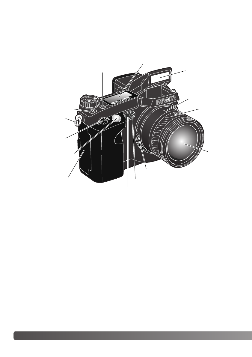
NAMES OF PARTS
CAMERA BODY
Data panel (p. 15)
Pro-auto button (p. 42)
Control dial
Shutter-release button
Focusing ring (p. 43)
Focal-length index
Zooming ring
1
Lens*
Card-slot door (p. 22)
The USB port is located behind
the card-slot door.
Self-timer lamp (p. 66)
Built-in flash (p. 30)
Digital-subject-program button (p. 32)
Strap eyelet (p. 18)
1 The focal-length scale on the zooming ring is given in 35mm focal-length equivalents. The DiMAGE
Viewer software supplied with the camera can display the actual focal length used to capture the recorded
image as well as the equivalent focal length in 35mm photography.
Microphone
NAMES OF PARTS
Page 13
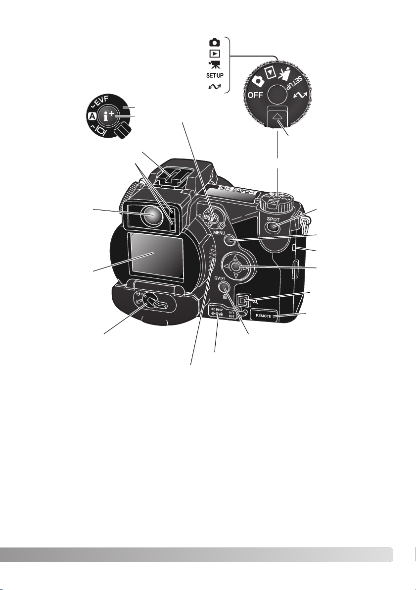
13
Accessory shoe
Display mode switch
Display information button
(p. 40, 36)
Electronic viewfinder*
(EVF) (p. 31)
LCD monitor*
(p. 16)
Menu button
Controller
DC/AV-out terminal cover
Spot-AE lock button (p. 43)
Battery-chamber lock (p. 20)
Eyepiece sensors*
(p. 40)
Magnification button
Remote-control
terminal cover (p. 57)
Access lamp
QV/ Delete button (p. 34)
Dial release
Main switch/Mode dial
Playback mode (p. 34)
Recording mode (p. 26)
Movie mode (p. 102)
Setup mode (p. 118)
Data-transfer mode (p. 132)
Speaker
Page 14
14
N
AMES OF PARTS
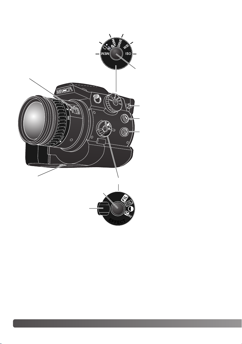
Function button
Macro release (p. 47)
Focus-mode (AF/MF) button (p. 43)
Digital-effects switch
Diopter-adjustment dial (p. 31)
Tr ipod socket
Memory (p. 50)
Metering modes (p. 51)
Exposure modes (p. 52) Drive modes (p. 58)
White balance (p. 67)
Camera sensitivity (p. 70)
Digital-effects button
Function dial (p. 48)
Digital-effects Controller (p. 73)
Flash sync terminal (p. 72)
Page 15
15
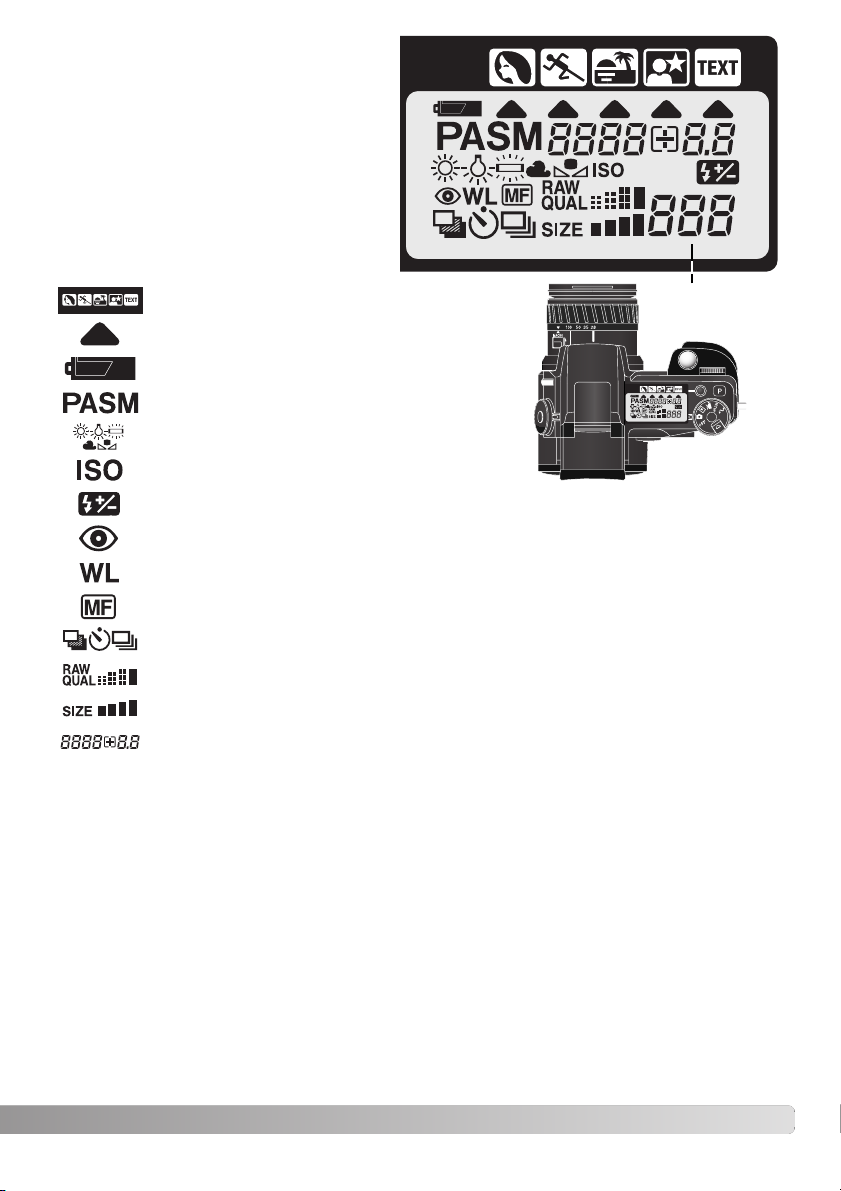
DATA PANEL
Digital-subject-program indicators (p. 32)
Camera-sensitivity indicator (p. 70)
Exposure-mode indicators (p. 52)
Battery-condition indicator (p. 21)
White-balance indicators (p. 67)
Red-eye reduction indicator (p. 88)
Manual-focus indicator (p. 43)
Image-quality display (p. 85)
Image-size display (p. 84)
Flash-compensation indicator (p. 74)
Digital-subject-program icons (p. 32)
Drive-mode indicators (p. 58)
Frame counter
(p. 84)
Located on the top of the camera body, the
data panel shows the status of the camera.
All icons have been shown for clarity.
The frame counter cannot exceed
999. When the number of recordable images exceeds this, 999 will
be displayed. The frame counter
will continue to count down when
the number of recordable images
falls below one thousand.
Wireless/Remote flash indicator (p. 90)
Shutter-speed and aperture display/exposure/flash compensation display
Page 16

7. Color-saturation-compensation display (p. 77)
16
N
AMES OF PARTS
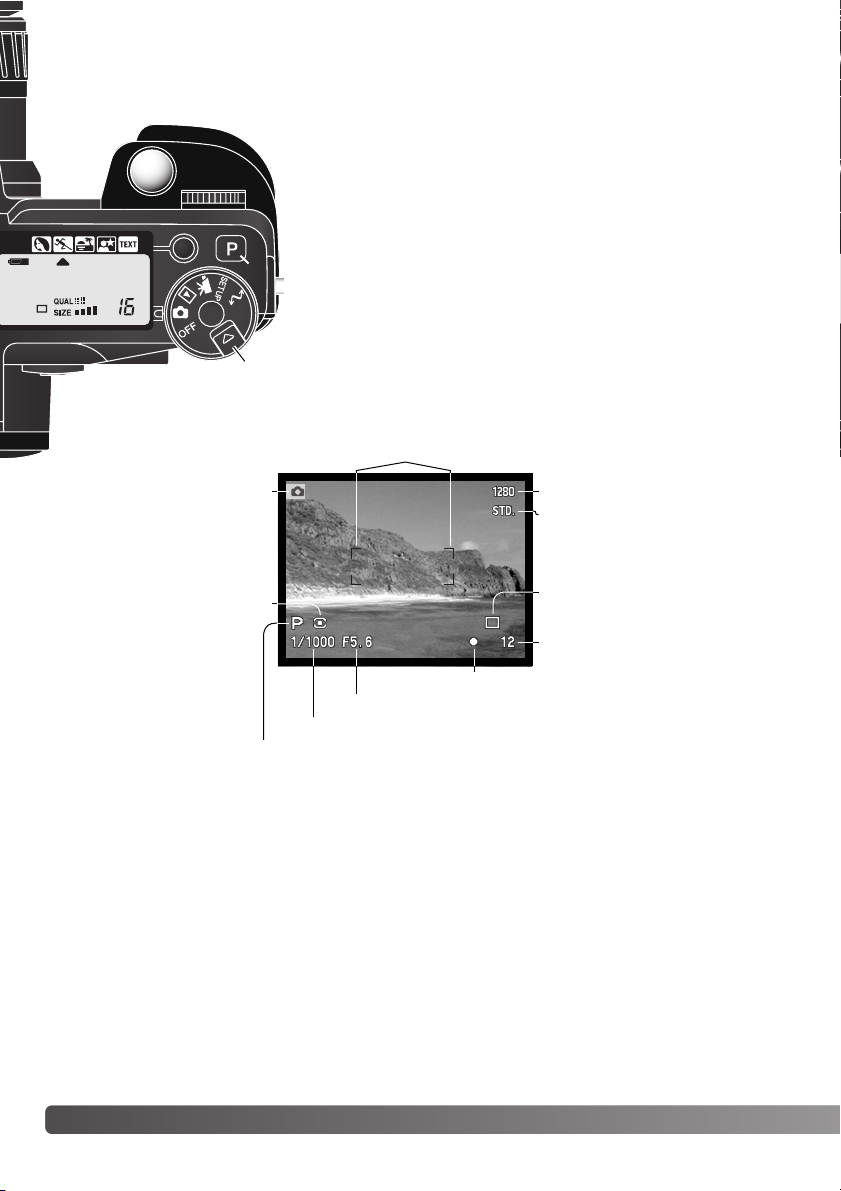
MONITOR DISPLAY – RECORDING MODE
2. Flash-mode indicator (p. 88)
5. Flash-compensation display (p. 74)
9. Sharpness display (p. 99)
8. Contrast-compensation display (p. 76)
10. Exposure-compensation display (p. 74)
11. White-balance indicator (p. 67)
17. Camera-sensitivity (ISO) display (p. 70)
12. Exposure-mode/Digital-subject-program
indicator (p. 52, 32)
13. Metering-mode indicator (p. 51)
14. Shutter-speed display
23. Manual-focus indicator (p. 43)
18. Macro-mode indicator (p. 47)
22. Drive-mode indicator (p. 58)
19. Focus signal (p. 29)
21. Frame counter (p. 84)
27. Digital-zoom display (p. 46)
26. Image-size display (p. 84)
25. Image-quality indicator (p. 85)
24. Battery-condition indicator (p. 21)
4. Mode indicator
3. Flash signal (p. 30)
A. Focus frame
B. Spot metering area (p. 51)
C. AF sensors
D. Flex Focus Point (p. 45)
1. Microphone indicator
6. Filter display (p. 77)
16. Camera-shake warning (p. 31)
15. Aperture display
20. Data-imprinting indicator (p. 97)
28. Color-mode indicator (p. 98)
Page 17
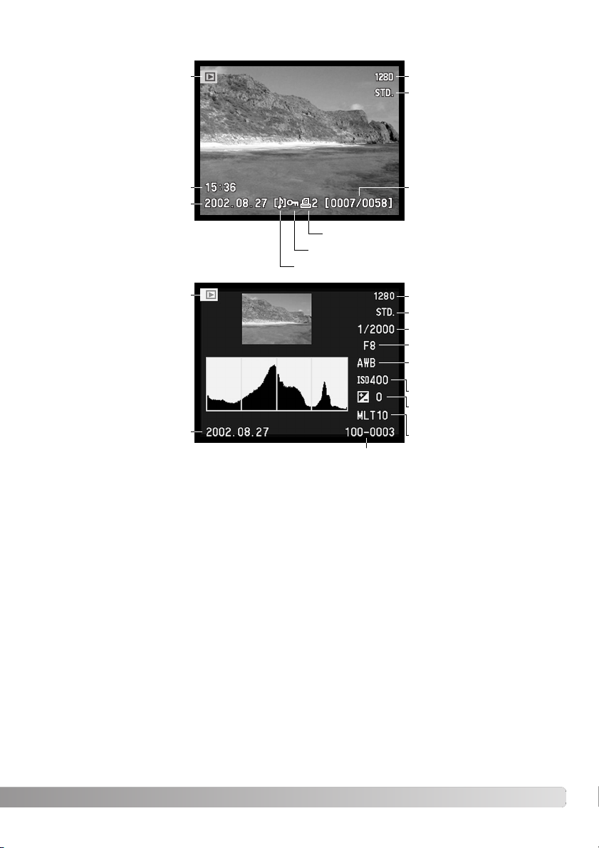
17
Shutter speed
Aperture value
White-balance setting
(p. 67)
Sensitivity setting (p. 70)
Degree of exposure
compensation (p. 74)
Folder name (p. 140)
Folder number – image file number
Histogram
Image size (p. 84)
Image quality (p.85)
Date of capture
Mode indicator
The black area of the histogram shows the luminance distribution of the recorded image from black
(left) to white (right). Each one of the 256 vertical lines indicates the relative proportion of that light
value in the image. The histogram can be used to evaluate exposure and contrast, but displays no
color information.
MONITOR DISPLAY – QUICK VIEW & PLAYBACK MODE
Date of capture
Frame number/
total number of images
Lock indicator (p. 111)
Print indicator (p. 114)
Image size (p. 84)
Image quality (p. 85)
Time of capture
Mode indicator
Voice-memo indicator (p. 101)
Page 18
18
G
ETTING UP AND RUNNING
GETTING UP AND RUNNING
This section covers the preparation of the camera. This includes the changing of batteries and memory card as well as the use of external power supplies.
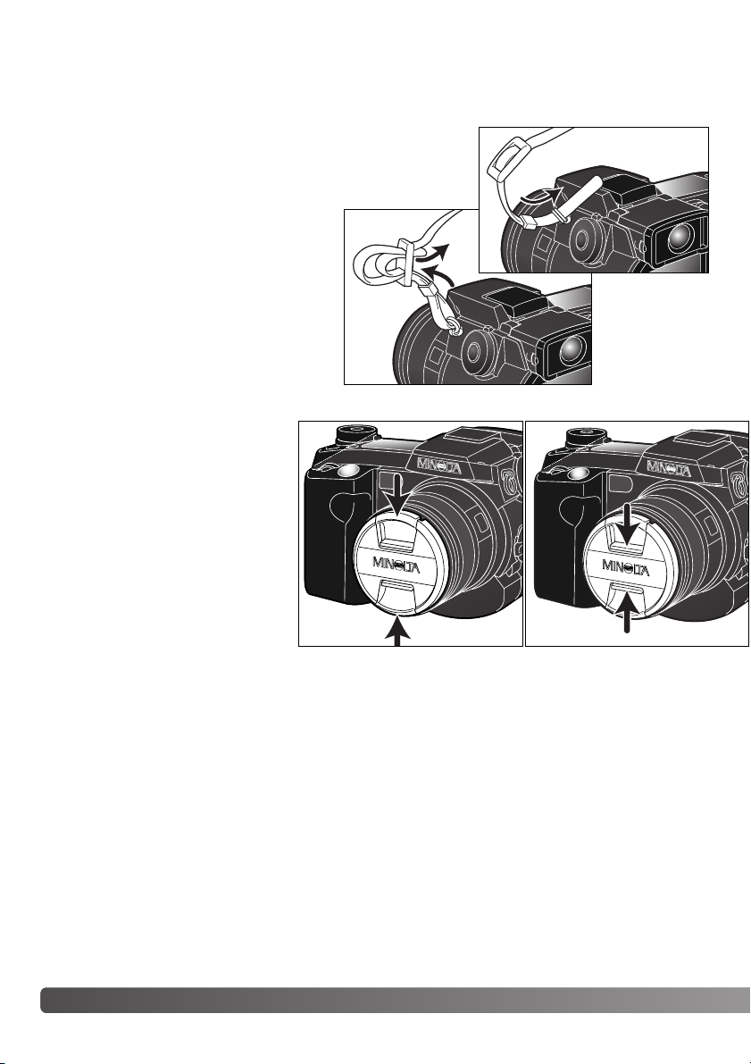
AT TACHING THE CAMERA STRAP
REMOVING THE LENS CAP
Using your thumb and index finger,
pinch the inside or outside tabs of
the lens cap to remove. When the
camera is not in use, always replace
the lens cap.
Attach the camera strap to the strap eyelets
as shown. Always keep the camera strap
around your neck in the event that you drop
the camera.
The neck strap is made with leather. Water
may stain the strap. When the strap is wet
or in contact with light colored material, the
strap may stain the wearers clothing.
1
2
Page 19
19
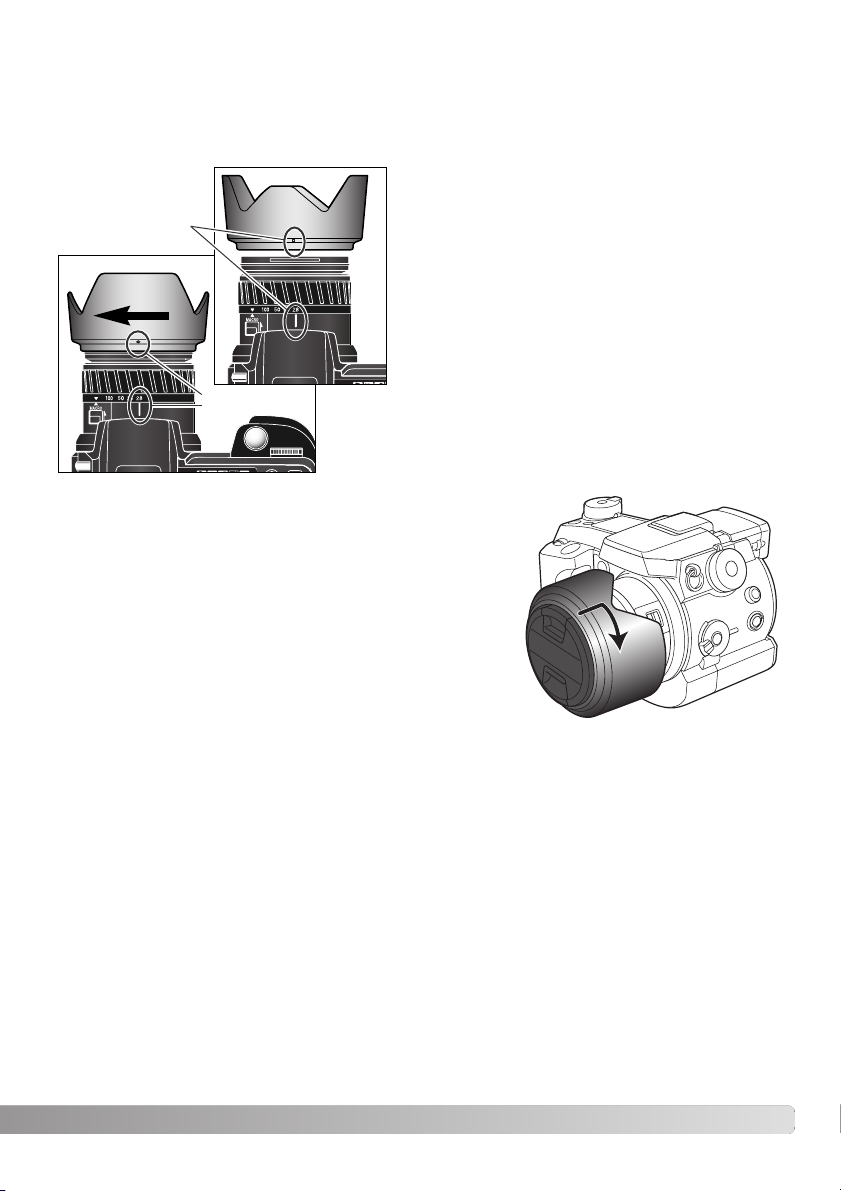
AT TACHING THE LENS HOOD
To mount the lens hood, align the rectangular dimple
on the rim of the hood with the focal-length index on
the top of the lens barrel (1).
Slide the hood onto the end of the lens and turn it
90° clockwise until it clicks and the circular dimple is
aligned with the focal-length index (2). When mounted correctly, the large petals of the lens hood should
be to the top and bottom. Never force the lens hood.
If it does not fit, check its orientation. To detach the
lens hood, turn it 90° counterclockwise and remove.
The lens hood can be reverse mounted when the camera is
not is use.
With one of the large petals to the top, slide the hood onto the
end of the lens. Turn it 90° clockwise until it it clicks into place.
The lens hood can be attached or removed with the lens cap
on the camera. To detach the lens hood, turn it 90° counterclockwise and remove.
The lens hood is used to control stray light from entering the lens and causing flare. When using the
camera under bright light, the use of the lens hood is recommended. The lens hood should not be
used with the built-in flash as it can cause a shadow.
2
1
Page 20
20
G
ETTING UP AND RUNNING
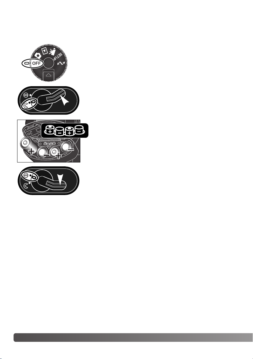
INSTALLING AND CHANGING BATTERIES
Open the battery-chamber door by moving the battery-chamber lock
to the open position.
Insert the batteries. Make sure the positive and negative battery
terminals are orientated as illustrated on the diagram in the battery chamber.
This digital camera uses four AA-size nickel-metal hydride (Ni-MH) batteries. When using new Ni-MH
batteries, fully charge them before their initial use.
When replacing batteries, check that the mode dial is in the off position.
Close the battery-chamber door and slide the lock lever to the close
position.
Although alkaline batteries can be used with this product, their performance will be limited. Only use
alkaline batteries for test photographs or when Ni-MH batteries, the Minolta External High-power
Battery Pack, or AC adapter are not available.
Page 21
21
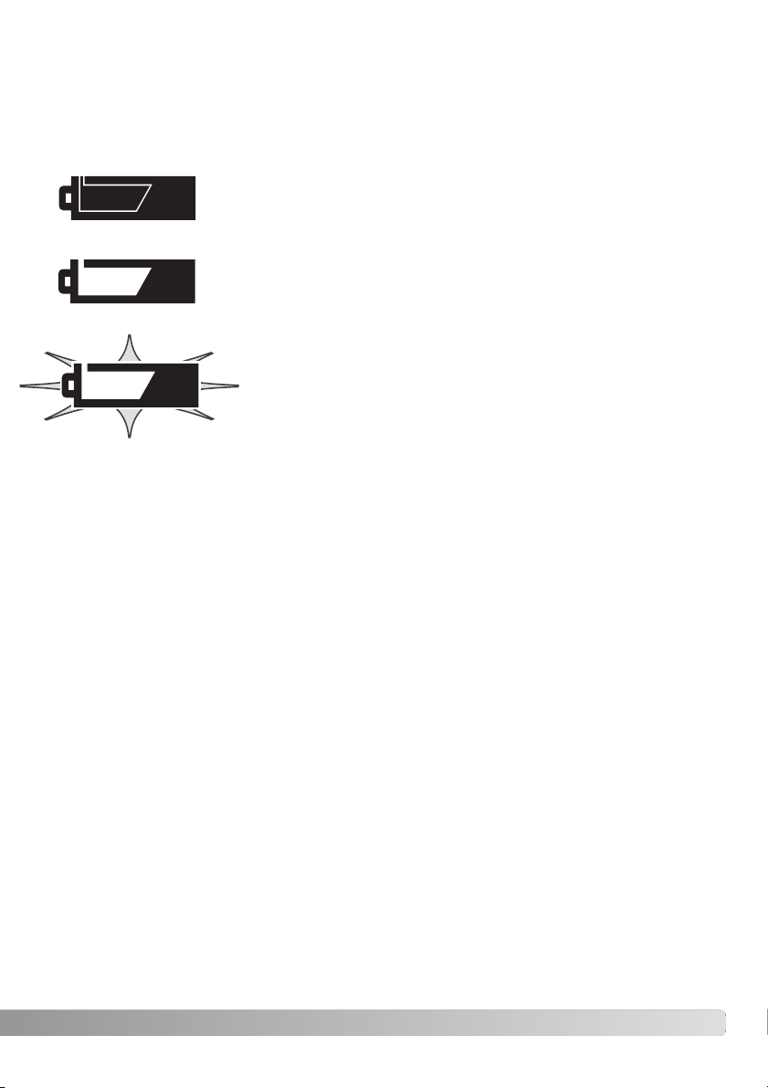
BATTERY CONDITION INDICATOR
Full-battery – the batteries are fully charged. This icon is displayed for
five seconds on the monitors when the camera is turned on. The icon
remains on the data panel.
Blinking low battery warning – displayed on the data panel with no other
icons. Power is insufficient for camera operation. The shutter will not
release. Replace or recharge the batteries immediately.
Low battery warning – battery power is very low, but all functions are
operational. The batteries should be replaced as soon as possible. This
warning automatically appears and remains on the display until the batteries are changed.
AUTO POWER SAVE
To conserve battery power, the camera will turn off displays and unnecessary functions if an operation is not made within a certain period. The LCD monitor will turn off after thirty seconds, and the
EVF and data panel turn off after one minute. To restore the displays, press the shutter-release button partway down or press the display-information button. The length of the auto-power-save period
for the EVF and data panel can be changed in the advanced 2 section of the setup menu (p. 118).
This camera is equipped with an automatic battery-condition indicator. When the camera is on, the
battery-condition indicator appears on the data panel and monitors. The monitor icon will change
from white to red when battery power is low. If the data panel and monitors are blank, the batteries
may be dead or installed incorrectly.
Page 22
22
G
ETTING UP AND RUNNING
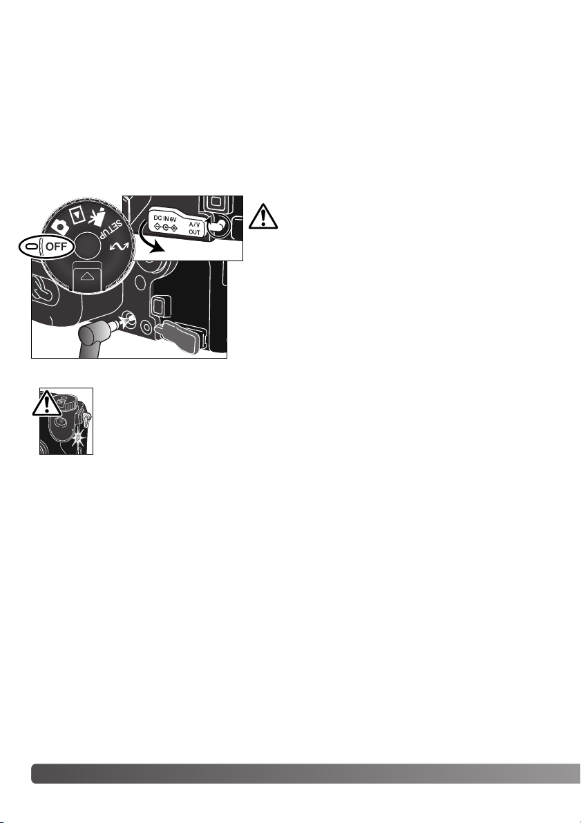
EXTERNAL POWER SUPPLIES (SOLD SEPARATELY)
INSERTING AND CHANGING A MEMORY CARD
The AC Adapter allows the camera to be powered from an electrical household outlet. The AC
Adapter is recommended when the camera is interfaced with a computer or during periods of heavy
use. AC Adapter model AC-1L is for use in North America, Japan, and Taiwan, and AC-2L is for use
in all other areas.
The External High-power Battery Pack Kit EBP-100 is a portable power source and significantly
extends the operating time of the camera. The kit contains a high-power lithium-ion battery, holder,
and charger. The battery, holder, and charger are also available separately.
Insert the mini plug of the AC adapter or battery pack into the
DC terminal (2).
Insert the AC adapter plug into an electrical outlet.
Remove the DC terminal cover from the left (1). The cover is
attached to the body to prevent loss.
A memory card must be inserted for the camera to operate. If a card has not been inserted, a nocard warning will be displayed on the monitors. Type I and II CompactFlash cards and IBM
Microdrives are compatible with this camera. For memory card care and handling, see page 149.
Always turn off the camera and confirm the access
lamp is not lit before changing between power supplies.
Always turn off the camera and confirm the access lamp is not lit before inserting or
removing a memory card, otherwise the card may be damaged, and data lost.
1
2
Page 23
23
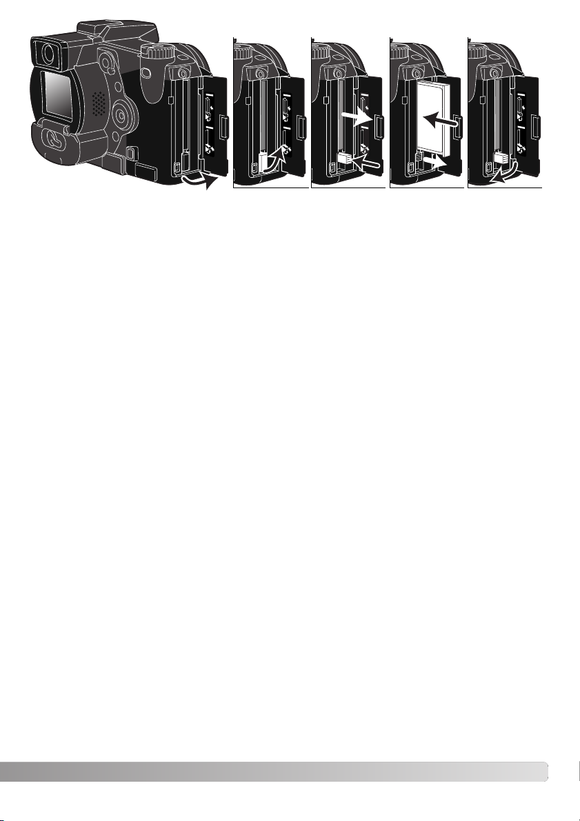
Open the card-slot door in the direction indicated (1).
To eject a memory card, lift (2) then press (3) the card-eject lever. The card can now be pulled out.
Ta ke care when removing the card as it becomes hot with use.
Insert a memory card into the card slot until the card-eject lever pops out (4). Insert the card so the
face is toward the front of the camera. Always push the card in straight. Never force the card. If the
card does not fit, check that it is orientated correctly.
Fold the card-eject lever down as shown (5) and close the card-slot door.
If the card-not-recognized message appears, the inserted card in the camera may need to be formatted. A memory card used in another camera may have to be formatted before being used. If the
unable-to-use-card message appears, the card is not compatible with the camera and should not be
formatted. A card can be formatted in the basic section of the playback menu (p. 106). When a card
is formatted, all the data on the card is permanently erased. If the card-error message appears,
press the central button of the controller to close the window; check the Minolta web site for the latest
compatibility information: North America: http://www.minoltausa.com, Europe: http://www.minoltaeurope.com/pe/digital/languages_stage.html.
12345
Page 24

24
G
ETTING UP AND RUNNING
SETTING THE DATE AND TIME
After initially inserting a memory card and battery, the camera’s clock and calendar must be set.
When images are recorded, the image data is saved with the date and time of recording. Depending
on the region, the menu language may also have to be set. To change the language, see the camera
notes on the following page.
Tu rn the mode dial on the top of the camera to the setup position. The camera will
turn on and the setup menu will be displayed.
The central button of the controller selects menu options
and sets adjustments.
Setup
Basic Adv.1
Adv.2
LCDbrightness
EVFbrightness
Audio signals
Shutter FX
Volume
3
3
1
1
2
Language
English
Cust.
Navigating the menu is simple. The up/down and left/right keys of the controller (1) move the cursor and change settings on the menu.
Controller
Page 25
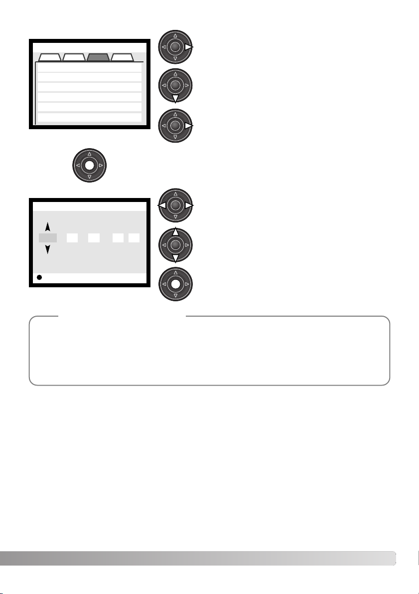
25
Use the right controller key to highlight the advanced
2 tab at the top of the menu.
Use the down key to highlight the date/time-set menu
option.
Press the central button to display the date/time setting screen.
Use the left and right keys to select the item to be
changed.
Press the central button to set the clock and calendar. The setup menu will be displayed.
Press the right key. “Enter” will appear on the right
side of the menu.
Advanced 2 section
Date/Time setting screen
Use the up and down keys to adjust the item.
For customers in certain areas, the menu language must also be set. Highlight the language
option in the basic section of the setup menu. Press the right key to display the language settings. Using the up/down keys, highlight the desired language. Press the central button to set
the highlighted language; the setup menu will be displayed in the selected language.
Camera notes
Setup
Basic Adv.1
Adv.2
Reset default
EVF autoSwtch
Date/Time set
Date format
Video output
–
Auto EVF/LCD
–
MM/DD/YYYY
NTSC
Powe r s ave
1 min.
Cust.
Enter
Setup
Date/Time set
2001 7 20 16 33:..
Page 26
1
2
26
B
ASIC RECORDING
SETTING THE CAMERA TO RECORD IMAGES AUTOMATICALLY
EVF AND LCD MONITOR DISPLAY
While holding in the dial release (1), turn the mode dial to stillimage recording; the electronic viewfinder (EVF) and LCD monitor
will activate. Press the pro-auto button (2) to reset the programmed
and automatic functions.
All camera operations are now fully automatic. The autofocus, exposure, and imaging systems will work together to bring professional
results effortlessly.
Metering-mode
indicator (p. 51)
Shutter-speed display
Aperture display
Drive-mode indicator (p. 58)
Focus signal (p. 29)
Frame counter (p. 15, 84)
Image-size display (p. 84)
Image-quality indicator (p. 85)
Mode indicator
Focus frame
Exposure-mode/Digital-subject-program indicator (p. 52, 32)
BASIC RECORDING
Page 27
3
4
27
BASIC RECORDING OPERATION
Place the subject within the focus frame.
•For off-center subjects use the focus-lock function (p. 28).
• Make sure the subject is within the focus range of the lens: 0.5m
(1.6ft) – ∞.For subjects closer than 0.5m, use the macro function
(p. 47).
Press the shutter-release button all the way down (4) to take the
picture.
The access lamp will glow indicating the image data is being
written to the memory card. Never remove a card while data is
being transferred.
Tu rn the mode dial to the recording position (1). Use the zooming ring to frame the subject (2). The effect of the zoom is immediately displayed in the viewfinder (EVF) and LCD monitor.
Press the shutter-release button partway down (3) to lock the
focus and exposure.
• The focus signals (p. 29) on the monitors will confirm that the
image is in focus. If the focus signal is red, the camera was unable
to focus on the subject. Repeat the previous steps until the signal
is white.
• When the focus is set, an AF sensor will briefly appear in the live
image to indicate the point of focus.
• The shutter speed and aperture value will change from white to
black indicating the exposure is locked.
• The live image may freeze for an instant as the AF system
determines focus.
2
1
Page 28
28
B
ASIC RECORDING
FOCUS LOCK
The focus-lock function is used when the subject is off-center and outside the focus frame. Focus
lock may also be used when a special focusing situation prevents the camera from focusing on the
subject.
Place the subject within the focus frame. Press and hold the
shutter-release button partway down.
• The focus signals will indicate that the focus is locked. The
shutter speed and aperture value will change from white to
black indicating the exposure is locked.
• When the focus is set, an AF sensor will briefly appear on the
live image to indicate the point of focus.
Without lifting your finger from the shutter-release button,
recompose the subject within the image area. Press the shutter-release button all the way down to take the picture.
AUTOMATIC MONITOR AMPLIFICATION
In extremely low-light conditions when the camera-sensitivity gain has reached its limit, the automatic
monitor-amplification function will intensify the EVF and LCD monitor image. The live image will be
brighter, however, the display will be black and white. This will have no effect on the final color image.
When the automatic monitor amplification activates, the electronic-magnification function (p. 95) cannot be used. If the real-time histogram (p. 40) is used, the display will reflect the amplified image and
not the final values of the exposure.
Page 29
This digital camera has a quick, accurate autofocusing system. The focus signals in the lower right
corner of the EVF and LCD monitor indicate the focus status. For more information on autofocus
modes see p. 83.
FOCUS SIGNALS
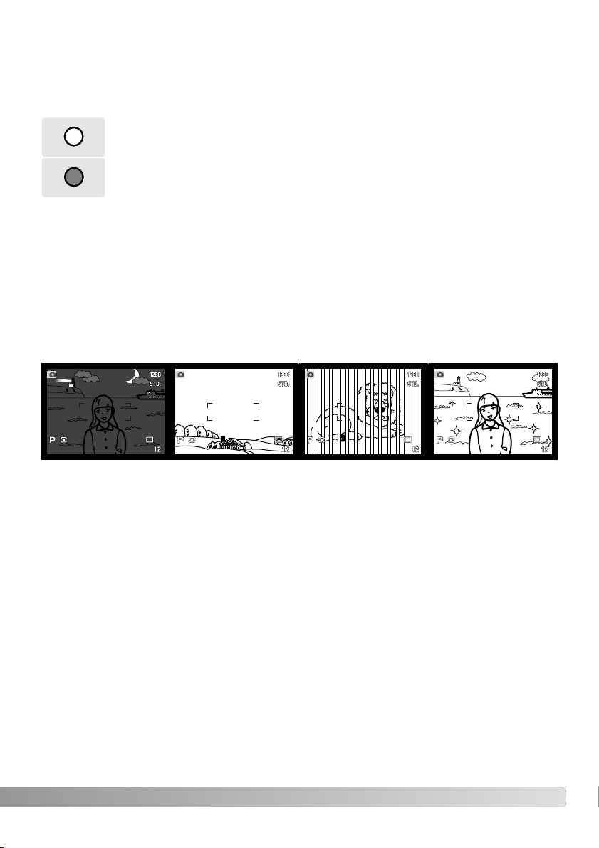
SPECIAL FOCUSING SITUATIONS
The camera may not be able to focus in certain situations. If the autofocus system cannot focus on a
subject, the focus icon will turn red. In this situation the focus-lock function can be used to focus on
another object at the same distance as your main subject, and then the image can be recomposed to
take the picture.
The subject in the
focus frame is low in
contrast.
The subject is too dark. Tw o subjects at differ-
ent distances overlap
in the focus frame.
The subject is near a
very bright object or
area.
29
When the AF system cannot focus, the focus is set between 5 m and infinity (16.4 ft and ∞). When
the flash is in use, the focus is set between 3.0 m and 3.8 m (9.8 ft and 12.5 ft). In this case, focus
lock can be used with an object at the same distance as the main subject or the camera can be
focused manually (p. 43).
White focus indicator – focus confirmed.
Red focus indicator – the subject is too close or a special situation is preventing the
AF system from focusing. The shutter can be released.
Page 30

30
B
ASIC RECORDING
USING THE BUILT-IN FLASH
FLASH RANGE – AUTOMATIC OPERATION
To use the flash, simply pull up the unit by the tabs on each side.
The flash position must be set manually, and once up, the flash unit
will always fire regardless of the amount of ambient light. The following indicators will appear in the upper left corner of the EVF and
LCD monitors to show the flash status
The camera will automatically control the flash output. For well-exposed images, the subject must be
within the flash range. Because of the optical system, the flash range is not the same at the lens’
wide-angle position as it is at the telephoto position.
Wide-angle position
Telephoto position
0.5m ~ 3.8m (1.6 ft. ~ 12.5 ft.)
0.5m ~ 3.0m (1.6 ft. ~ 9.8 ft.)
Flash warning. In backlit situations, the icon appears to recommend the use of the flash.
When pressing the shutter-release button partway down, the white flash icon indicates
the flash is ready to fire.
When pressing the shutter-release button partway down, the red flash icon indicates the
flash is charging.
After taking a picture, a blue flash icon appears if the flash properly exposed the subject.
In low-light conditions or indoors, the flash is needed to illuminate the subject and reduce blurring
through camera shake. The flash can also be used as a fill light in direct sunlight to soften harsh
shadows. Always remove the lens hood when using the built-in flash; the hood may cast a shadow if
mounted.
Page 31

While using the electronic viewfinder (EVF) or LCD monitor, grip the
camera firmly with your right hand while supporting the body with the
palm of your left hand. Keep your elbows at your side and your feet
shoulder-width apart to hold the camera steadily.
HANDLING THE CAMERA
CAMERA-SHAKE WARNING
The EVF has a built-in diopter that can be adjusted between
–5.0 to +0.5. While looking through the EVF, turn the diopteradjustment dial until the viewfinder image is sharp.
The electronic viewfinder can be tilted between 0° to 90°.
Simply grip the finder between your fingers and move it to the
position desired. Always store the camera with finder down
against the body.
If the shutter speed falls below the point where the camera can be hand held safely, the camerashake warning will appear on the monitors; the shutter can still be released. Camera shake is slight
blurring caused by subtle hand motion and is more pronounced at the telephoto setting of the lens
than at the wide-angle. The warning appears at approximately the reciprocal of the focal length used;
if the lens is set at 100mm, the camera shake warning will appear at 1/100 second. If the warning
appears, the following steps can be taken:
• Place the camera on a tripod.
• Use the built-in flash.
• Increase the camera sensitivity (ISO) (p. 70).
• Zoom the lens towards the wide-angle position.
31
DIOPTER ADJUSTMENT
Page 32

32
B
ASIC RECORDING
DIGITAL-SUBJECT-PROGRAM BUTTON
The digital-subject-program button (1) optimizes the camera’s
performance for various conditions and subjects. Exposure,
white-balance, and image-processing systems work in unison
for beautiful results.
Pressing the digital-subject-program button cycles through
the modes: portrait, sport action, sunset, night portrait, text,
and the original exposure mode. A pointer will indicate the
active subject program. The subject program will remain in
effect until it is changed.
Portrait – optimized to reproduce warm, soft skin tones and a slight defocusing of the
background.
Sports action – used to capture fast action by maximizing shutter speeds and tracking
subjects with continuous AF.
Sunset – optimized to reproduce rich, warm sunsets.
Night portrait – for deep, subtle night scenes. When used with flash, the subject and
background are balanced.
Te xt – for the crisp reproduction of black text on white backgrounds.
1
Page 33

33
While camera performance is optimized for each shooting condition, some changes can be made to
camera settings with subject programs. The autofocus mode can be changed (p. 83). The sports
action mode uses continuous AF, the other modes use single AF.The Digital Effects Controller can
be used to adjust image brightness, contrast, and color (p. 73). White balance can be changed in all
modes except sunset and night portrait (p. 67). Sharpness can be changed in the sport action, sunset, and text modes (p. 99). The metering mode cannot be changed.
Portrait – Most portraits look best at a telephoto setting; the longer focal length does not exaggerate facial features and the shallower depth of field softens the background. Use the built-in
flash with strong direct sunlight or backlight to reduce harsh shadows.
Sports action – When using a flash, make sure the subject is within the flash range (p. 30).
The flash range can be extended by changing the camera sensitivity (p. 71). A monopod is
more flexible and compact than a tripod when shooting events.
Sunset – When the sun is above the horizon, do not point the camera toward the sun for prolonged periods of time. The intensity of the sun could damage the CCD. Between exposures,
turn off the camera or cover the lens.
Night portrait – When taking pictures of a landscape at night, use a tripod to eliminate blurring
from camera shake. The flash can only be used with close subjects such as with a portrait of a
person. When using the flash, ask your subjects not to move after the burst; the shutter will still
be open for the background exposure.
Text – When taking pictures of small text on a sheet of paper, the macro mode (p. 47) can be
used. Use a tripod to eliminate camera shake and ensure the sharpest images.
Shooting tips
Page 34

To view images from the playback mode, turn the mode
dial to the playback position.
To view images from the recording or movie recording
modes, press the Quick View / delete button.
34
B
ASIC PLAYBACK
SINGLE-FRAME PLAYBACK AND HISTOGRAM DISPLAY
Date of capture
Frame number/ total number of images
Lock indicator (p. 111)
Print indicator (p. 114)
Image size (p. 84)
Image quality (p. 85)
Time of
capture
Mode indicator
Voice-memo
indicator (p. 101)
To view the histogram,
press the up key.
Shutter speed
Aperture value
White-balance
setting (p. 67)
Sensitivity
setting (p. 70)
Degree of exposure
compensation (p. 74)
Folder name (p. 140)
Folder number – image file number
Histogram (p. 17)
Images can be viewed in the Quick View or playback modes. This section covers the basic functions
in both modes. The playback mode has additional menu functions, see page 106.
BASIC PLAYBACK
Page 35

35
To return to a recording mode from Quick
View, press the menu button.
Controller
QV/Delete button
VIEWING IMAGES
To delete a displayed image, press the QV/delete button; a
confirmation screen will appear.
The displayed image can be deleted. Once deleted, an image cannot be recovered.
Press the controller to execute the command on the confirmation screen. The camera will return to playback mode.
DELETING SINGLE IMAGES
Use the left/right keys to highlight “Yes.” “No” will cancel the
operation.
Confirmation screen
Delete this frame?
NoYe s
When in the Quick view or playback mode, use the
left/right keys of the controller to scroll through the
images on the memory card.
To view the histogram of a still image,
press the up key. Press the down key to
return to single-frame playback.
Page 36

36
B
ASIC PLAYBACK
In the center of the display switch, the display-information button controls the display format. Each
time the button is pressed, the display cycles through to the next format: full display, image only,
index playback.
Full display Image only
Index playback
In index playback, the left/right keys of the controller will move the yellow border to the next or the
previous image. When the image is highlighted with the border, the date of recording, voice-memo
icon, the lock and printing status, and the frame number of the image are displayed at the bottom of
the screen. The highlighted image can be deleted using the QV/delete button (p. 35) or an accompanying audio track can be played by pressing the central button of the controller. When the display
information button is pressed again, the highlighted image will be displayed in the single-frame playback mode. A nine or four image index can be displayed. The index-playback format can be changed
in the basic section of the playback-mode menu (p. 106).
CHANGING THE QUICK VIEW & PLAYBACK DISPLAY
Page 37

37
ENLARGED PLAYBACK
In single-frame playback, a still image can be
enlarged for closer examination. Images can be magnified between 1.2X and 4.0X in 0.2X increments. 640
X 480 size images can only be magnified between
1.2X and 2.0X. RAW and super fine images cannot
be enlarged.
With the image to be enlarged displayed, press the
magnification button (1). The degree of magnification
is displayed on the monitors.
1
Use the up/down keys of the controller to adjust the magnification.
Press the central button of the controller to switch between the
zoom and scroll functions. The scroll arrows or magnification display will turn blue to indicate the active function.
When the scroll arrows are blue, use the four-way key to scroll
the image. Press and hold the four-way key to scroll continuously. Press the magnification button to exit the enlarged playback
mode.
The guidance bar and display icons can be hidden or shown by
pressing the display information button (i+).
Scroll
Scroll
Zoom
Page 38

38
B
ASIC PLAYBACK
Standard, Night, time-lapse, and UHS continuous-advance movies can be played back on the camera. Movie files are indicated by a icon at the bottom of the display. Standard and Night Movies are
also indicated by a thumbnail of the first frame.
Press the center of the controller to play back the file.
To cancel the playback, press the down key of the controller.
VIEWING MOVIES
: play
: pause : stop 23s
Press the controller to pause the movie; pressing the
controller again will resume the playback.
PLAYING BACK VOICE MEMOS
Controller
Press the central button of the controller
to start the audio playback. To cancel the
playback, press the down key.
Voice memos (p. 101) are indicated by the
voice-memo indicator displayed at the bottom of
the monitor image.
Page 39

39
VIEWING IMAGES ON A TELEVISION
It is possible to view camera images on your television. The camera has a video-out terminal which
can be used to connect the camera to a television using the supplied AV cable. The camera is compatible with the NTSC and PAL standards. The video-output setting can be checked and set in the
advanced 2 section of the setup menu (p. 118).
Tu rn off the television and the camera.
Insert the mini-plug end of the AV cable into the camera’s
AV-out terminal.
Plug the other end of the AV cable into the video and
audio input terminal on the television. The yellow plug is
for the video output, and the white plug is for the monaural audio output.
Tu rn the television on.
Tu rn the camera’s mode dial to the playback position. The
camera’s monitors will not activate when the camera is
attached to a television. The playback-mode display will
be visible on the television screen.
Change the television to the video channel.
View images as described in the playback section. Use the television controls to adjust the volume of the audio playback. Because of the broadcast standard used to display television images,
image quality and resolution will appear lower than when displayed on a computer monitor.
2
1.
2.
3.
4.
5.
6.
7.
3
Page 40

40
A
DVANCED RECORDING
DISPLAY CONTROLS – RECORDING MODE
Auto display – the camera will automatically change between displaying the
live image in the EVF or on the LCD monitor. The EVF’s eye sensors monitor
if the EVF is being used and switches the display location accordingly.
EVF display – the live image will only be displayed in the electronic viewfinder. Under bright light, the image is easier to see in the EVF than on the LCD
monitor.
LCD monitor display – the live image will only be displayed on the LCD monitor.
Located on the back of the camera, the display-mode switch and the display-information button control on which monitor the image is displayed and what information is included in the display. The three
position switch allows the choice between automatic display and setting the display to the EVF or
LCD monitor.
If battery power is a concern, have the eye sensor activate the EVF when in use, but not the LCD
monitor. The auto-display function can be changed in the advanced 2 section of the setup menu (p.
118).
ADVANCED RECORDING
This section contains detailed information on the camera’s recording functions and operation. Read
the sections pertaining to your interest and need.
Page 41

41
In the center of the display switch, the display-information button controls what
information is displayed with the live image. Each time the button is pressed,
the display cycles to the next format: standard display, focus frame, real-time
histogram, and live image only. The number of screens and their formats can
be changed in the advanced 1 section of the setup menu (p. 118).
Standard display Focus frame
Live image only Real-time histogram
The real-time histogram shows the approximate luminance distribution of the live image. This histogram will not be accurate when the monitor image is amplified (p. 28, 56), or the built-in or a compatible Minolta flash unit is used. The histogram of a recorded image may not have the same distribution as the real-time histogram.
Page 42

42
A
DVANCED RECORDING
Flash mode
Color-saturation compensation
Exposure mode
PRO-AUTO BUTTON
Simply pressing the pro-auto button (1) resets the camera to programmed and automatic functions in the still-image recording mode.
The camera’s systems work together to bring professional results leaving the operator free to concentrate on aesthetic decisions. The proauto button affects functions in either the recording or movie modes (p.
105) only when the mode is in use.
Drive mode
White balance
Metering mode
Exposure compensation
Flash compensation
Focus mode
Autofocus area
Program (p. 53)
Single-frame advance (p. 58)
Auto white balance (p. 67)
Multi-segment metering (p. 51)
0.0 (p. 74)
0.0 (p. 74)
Fill or red-eye reduction* (p. 88)
Single AF (p. 83)
Wide (p. 44)
*The flash mode is reset to whichever of the two modes was set last.
Digital subject program Canceled (p. 32)
Flash control ADI metering (p. 94)
Contrast compensation 0 (p. 76)
0 (p. 77)
Sharpness Normal (p. 99)
Filter 0 (p. 77)
1
The last camera settings before the pro-auto
button is pressed can be reset; press and hold
the function button and press the pro-auto button.
Page 43

43
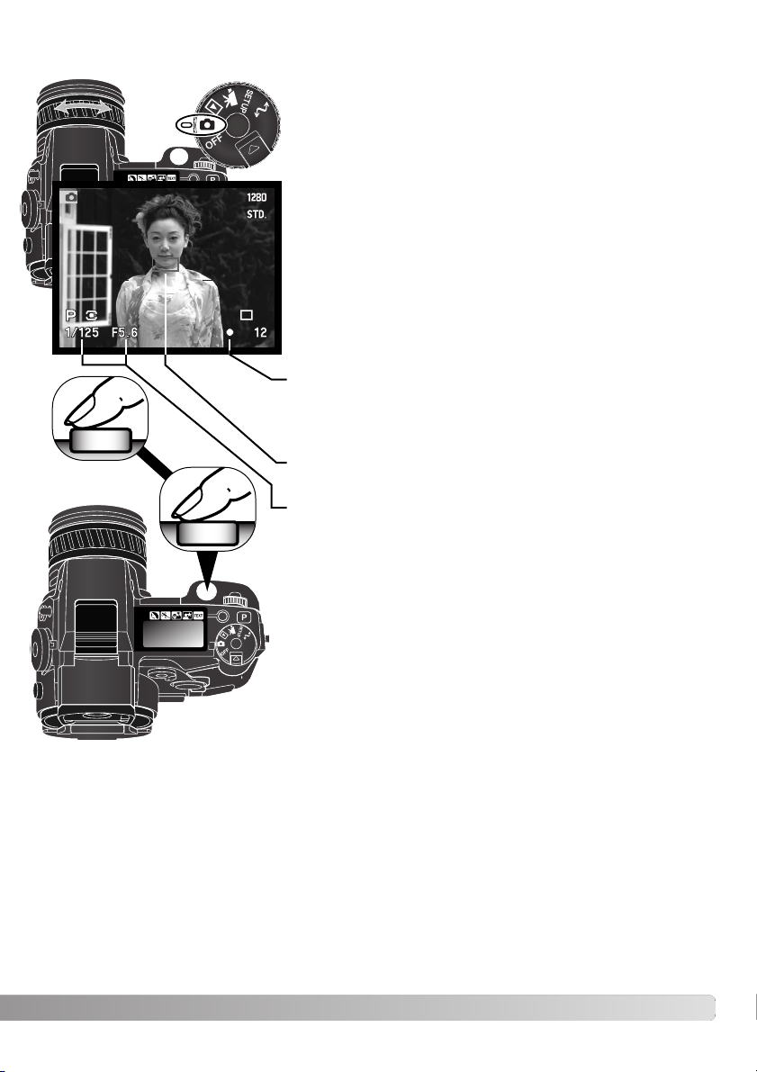
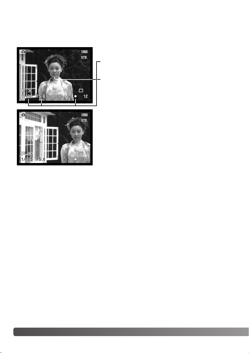
The spot-AE lock button below the main dial on the back of the body locks the automatic exposure system. This function allows the exposure to be set by a specific element within the scene or a gray card outside the scene.
When the spot-AE lock button is pressed and held, the spot metering circle is displayed indicating the area used for the exposure calculation; the shutter speed and
aperture of the exposure will be displayed in black on the monitor. The setting will
remain in effect until the button is released. Focus is locked by pressing the shutterrelease button partway down.
The operation of the spot button can be customized in the advanced 1
section of the recording-mode menu (p. 96).
SPOT-AE LOCK BUTTON
Manual control over focus is simple. The focus mode button
(AF/MF) (1) switches between automatic and manual focus.
The MF icon is displayed on the data panel and monitors
when the camera is in the manual-focus mode.
Use the focus ring (2) at the rear of the lens barrel to make a
sharp image on monitors. The approximate distance from the
CCD to the subject is displayed near the frame counter.
Manual focus can be used with movie recording and in macro
mode.
MANUAL FOCUS
2
1
Spot metering display
Approximate location of the CCD
plane.
Page 44

44
A
DVANCED RECORDING
AUTOFOCUS AREAS AND CONTROL
In still-image recording mode, the controller selects the focus area used and moves the spot-focus
area within the image. The two focus areas, wide focus area and spot focus point, allow flexibility over
a variety of situations.
The wide focus area is an array of local focus areas that work together to control focus. This system
is especially effective with moving subjects or quick shooting during fast-moving events. When the
focus is locked in single AF mode, one of the AF sensors within the wide focus area will briefly indicate the point of focus. The spot focus point gives critical control over focus. It can be used to single
out an individual subject from a group.
Wide focus area
AF sensor
Spot focus point
Switching between the wide focus area to the spot focus point is simple. Press and hold the central
button of the controller (1) until the wide-focus-area frame lines change to the spot-focus-point cross.
Press and hold the controller again to return to the wide-focus-area frame lines.
1
Page 45

45
FLEX FOCUS POINT
Once displayed, the spot focus area can be moved to any point in the image area. This Flex Focus
Point is a powerful tool for off-center subjects. The Flex Focus Point cannot be used with the digital
zoom (p. 46).
With the spot-focus-area cross displayed, use the controller’s four-way keys (1) to
move the focus point anywhere within the live image. Press the shutter-release button partway down to focus; the cross will turn red to confirm focus.
Pressing the central button of the controller (2) returns the focus point to the center
of the image area. To return to the wide-focus-area mode press and hold the button
until the wide-focus-area frame lines appear.
1
2
1
2
Page 46

1280 X 960
Image size setting
2560 X 1920 1600 X 1200 1280 X 960
640 X 480
1280 X 960 1280 X 960
640 X 480
Recorded
image size
46
A
DVANCED RECORDING
DIGITAL ZOOM
The digital zoom doubles the lens magnification. The digital zoom cannot be used with RAW image
quality or in movie recording.
Press the magnification button (1) on the back of the camera. The effect
is immediately displayed. Pressing the magnification button a second
time cancels the digital zoom.
The live image is enlarged on the LCD monitor and is cropped with a
shaded border in the EVF. X2.0 is displayed in the monitors when the
digital zoom is in effect. When using the wide focus area (p. 44), the AF
sensor will not appear to indicate the point of focus.
When an image is taken with the digital zoom, the final image size depends on the image-size setting
on the camera. The image is trimmed and then the total number of pixels are interpolated to produce
an image with a pixel resolution shown in the chart.
EVF
1280 X 960 UHS continuous-advance images are resized to 640 X 480.
LCD monitor
1
Page 47

47
The macro mode is used for close-up photographs of small objects. The marco mode can be used
with the digital zoom to increase the close-up effect. Subject programs and movie recording can be
used with the macro setting. The built-in flash cannot be used with macro mode.
Align one of the arrows on the zoom ring with the arrow next to the
macro switch. The lens must be zoomed to the wide-angle or telephoto
position for the macro switch to engage.
Slide the macro switch on the lens barrel forward. The camera is now in
macro mode. The macro icon is displayed in the lower right corner of the
monitors. Make sure the subject is within the macro focusing range:
Wide angle: 0.3 – 0.6m / 12 – 24 in from the CCD.
Telephoto: 0.25 – 0.6m / 10 – 24 in from the CCD.
The zoom ring will be locked at the wide-angle position in macro mode.
At the telephoto position, the zoom ring can move slightly to make fine
adjustments to image size.
To return to normal recording mode, slide the macro switch towards the
rear of the lens.
Because of the high image magnification, hand holding cameras during
close-up photography is very difficult. When possible, use a tripod.
Use the Flex Focus Point (p. 45) to specify the area to be within focus.
Because depth of field (the area in focus) is narrow in close-up photography, using focus lock with off-center subjects can cause minor errors
which are exaggerated at high magnifications.
The variable position EVF makes working in tight spaces and at low levels
easy. The EVF can be tilted between 0° and 90°.
Shooting tips
MACRO MODE
Approximate location of the
CCD plane.
Page 48

48
A
DVANCED RECORDING
SETTING THE FUNCTION DIAL
The memory function, metering mode, exposure mode, drive mode, white balance, and camera sensitivity are controlled by the function dial. Making changes with the function dial is simple. The function dial can only be used for still photography.
Tu rn the function dial to the mode to be changed (1).
While pressing the button in the center of the
function dial, turn the control dial near the
shutter-release button to change the mode
(2). Release the function button to set the
mode. Changes are displayed on the monitors
and data panel.
ISO
WB
DRIVE
P
ASM
MEM
Memory – to store and recall camera settings (p. 50).
Metering modes – changes the metering pattern (p. 51).
Exposure modes – changes the method of exposure control (p. 52).
Drive modes – changes the method of image capture (p. 58).
White balance – changes between automatic, preset, and custom white balance
(p. 67).
ISO – changes camera sensitivity (p. 70).
1
2
Page 49

49
Dial
MEM
PASM
DRIVE
WB
ISO
Display
P
A
S
100, 200,
400, 800.
Setting
Memory registers or the setting
function are selected with a special menu displayed on the monitors.
Multi-segment
Center weighted
Spot
Program
Aperture priority
Shutter priority
Manual
Single-frame advance
Continuous advance
Self-timer
Interval
Bracketing
Automatic white balance
Daylight
Tungsten
Fluorescent 1 and 2
Cloudy
Custom setting 1 through 3
Custom calibration
Automatic gain
Preset camera sensitivity in ISO
equivalents.
Page
50
51
53
54
55
56
58
62
60
61
64
68
68
68
70
EVF & Monitor Display
Menu
ISO value
is displayed
(No display when set)
UHS continuous advance
59
No data panel display.
66
High-speed continuous advance
(No display when set)
M
Display for the
data panel, EVF
and LCD monitor
are the same
unless indicated.
Page 50

50
A
DVANCED RECORDING
MEMORY – STORING CAMERA SETTINGS
Five sets of camera settings can be saved.This saves time under frequently
repeating conditions by eliminating the need to set the camera. Except for the
spot AEL button, subject programs, data imprinting, voice memo, and instant
playback settings, all recording-mode camera settings will be saved including the
position of the Flex Focus Point, the display mode, the custom white balance setting, and changes made with the function dial and digital effects control. Although
the bracketing drive mode setting can be saved, the type of bracket, exposure,
contrast, color saturation, or filter must be reset.
To save the current camera settings, turn the function dial to
the memory position, and press the function button (1) to display the memory settings on the monitor. Turn the control dial
(2) to highlight the store-memory option. Release the function
button to open the store-memory screen.
Memory 1
Memory 2
Memory 3
Store memory
1
2
Camera settings are saved with the function dial (p. 48).
Initially, each memory location contains the camera’s original
settings.
On the store-in-memory screen, use the up/down keys of the
controller (3) to select the memory register in which the camera settings are to be saved. Press the central button of the
controller (4) to save the settings; the previous settings will be
erased and replaced by the new ones. A confirmation screen
will open; press the central button of the controller to close.
Rec.
Store memory
select
enter
1
Store in
1
2
3
4
Memory 4
Memory 5
4
5
3
Page 51

51
METERING MODES
The icons indicating the metering mode are displayed on the monitors only. Do
not confuse these icons with the focus signals (p. 29). The metering mode is
changed with the function dial (p. 48). When center-weighted or spot metering is
selected, pressing the shutter-release button partway down will activate the
exposure system, but will not lock the exposure; the spot AE lock button (p. 43)
can be used to lock the exposure, but uses the spot metering area only.
Spot – uses a small area within the image to calculate the exposure. When this mode is selected, a small circle will appear in
the middle of the live image indicating the measuring area. The
spot allows precise exposure measurements of a particular
object without being influenced by extremely bright or dark
areas within the scene.
Multi-segment – uses 300 segments to measure luminance and color. This data is combined with distance information to calculate the camera exposure. This advanced metering
system will give accurate worry-free exposures in almost all situations.
Center weighted – a traditional metering method in silver-halide cameras. The system measures light values over the entire image area with emphasis given the central region.
Spot metering display
To recall a setting, press the function button and highlight the memory register using the control dial.
Release the function button to apply the memory settings. Memory settings can also be recalled
using the digital subject program button, see page 129.
Camera settings cannot be deleted from memory by turning the camera off or using the pro-auto button. They will be erased with the default function on the setup menu.
Page 52

52
A
DVANCED RECORDING
P
EXPOSURE MODES
A
S
M
Program – the camera controls both the shutter speeds and aperture.
Aperture priority – the photographer selects the aperture and the camera sets the appropriate shutter speed.
Manual exposure – the photographer selects both the shutter speed and aperture.
Shutter priority – the photographer selects the shutter speed and the camera sets the
appropriate aperture.
LCD monitor
Data panel
The four exposure modes allow extensive control over image making.
Programmed AE gives carefree operation, aperture and shutter priority allow
photographers to maximize exposures in different situations, and manual exposure provides complete freedom in controlling the final image. See setting the
function dial section on page 48.
All exposure mode icons on the data
panel have been shown for clarity.
Exposure modes
Shutter speed
Aperture
Page 53

53
PROGRAM – P
The programmed AE exposure control uses luminance and focal-length information to ensure perfect
exposures. The sophisticated exposure system allows the photographer the freedom to shoot without
having to worry about the technical details of exposure settings. The shutter speed and aperture values of the exposure are displayed on the monitors and data panel.The shutter speed range in program exposure mode is 8 to 1/4000 second when camera sensitivity is set to auto (p. 71). If the
brightness level of the scene is outside the exposure control range of the camera, the shutter-speed
and aperture displays will turn red on the monitors and blink on the data panel.
The program line adjusts with the changes in focal length of the zoom lens.The camera is programmed to maximize depth of field in the wide-angle range to provide sharp landscape pictures,
and to maximize shutter speed in the telephoto range to minimize camera shake and blurred images.
When the shutter speed falls below an acceptable limit for the camera to be hand held, the camerashake warning appears in the lower left corner of the monitors (p. 31).
PROGRAM SHIFT
Although exposure calculations can be left to the camera, photographers can still have control over
the final exposure with the program-shift function. As described in the basic recording operation (p.
31), press the shutter-release button partway down (1) until the shutter speed and aperture value are
displayed. The control dial (2) can then be used to shift the shutter speed and
aperture combination; each combination will give the optimum exposure.
The built-in flash cannot be used with program shift. The
camera gives priority to the flash exposure; once the flash is
raised, any changes made with the program shift will be canceled.
1
2
Page 54

The aperture values can be changed by half stop increments between f/2.8 and f/8 at the lens’ wideangle position and f/3.5 to f/9.5 at the lens’ telephoto position. If the aperture value is beyond the
shutter-speed range, the shutter-speed display will blink on the data panel and turn red on the monitors. The shutter speed range in aperture-priority exposure mode is 15 to 1/4000 second when camera sensitivity is set to auto (p. 71).
When the shutter speed falls below an acceptable limit for the camera to be hand held, the camerashake warning (p. 31) appears in the lower left corner of the EVF and LCD monitor. When the warning appears, decrease the aperture value until the warning disappears or place the camera on a tripod.
Because the shutter speeds can be adjusted in fine steps, the same shutter speed maybe displayed
when the aperture is changed. With the camera sensitivity (ISO) set to auto, the shutter speed may
not change when the aperture is adjusted.
The photographer selects the aperture and the camera sets the
appropriate shutter speed to ensure correct exposure. When A mode
is selected, the aperture value on the monitors turns blue.
Tu rn the control dial (1) to set the desired aperture. Press the shutter-release button partway down to activate the exposure system (2);
the corresponding shutter speed will be displayed.
54
APERTURE PRIORITY – A
1
2
A
DVANCED RECORDING
Page 55

The photographer selects the shutter speed and the camera sets the
appropriate aperture to ensure correct exposure. When S mode is
selected, the shutter speed on the monitors turns blue.
Tu rn the control dial (1) to set the desired shutter speed. Press the
shutter-release button partway down to activate the exposure system
(2); the corresponding aperture will be displayed.
55
SHUTTER PRIORITY – S
1
2
For 35mm photographers, an aperture range of f/2.8 to f/8 does not seem impressive. However,
because of the CCD size and the actual focal length of the lens, the apertures on this digital
camera give significantly more depth of field at any given angle of view with any given aperture
than a 35mm camera. So even with the minimum aperture of f/8, the depth of field will give the
coverage needed to create beautiful, sharp images.
Camera Notes
The shutter speeds can be changed by half stop
increments from 15 to 1/2000 second when camera
sensitivity is set to auto (p. 71). If the shutter speed is
beyond the aperture range, the aperture display will
blink on the data panel and turn red on the monitors.
Page 56

Manual exposure mode allows individual selection of shutter speeds
and apertures. This mode overrides the exposure system giving the
photographer total control over the final exposure. The shutter
speeds and aperture values can be changed in half stop increments.
The shutter speed range in manual exposure mode is 15 to 1/2000
second including bulb when camera sensitivity is set to auto (p. 71).
The camera sensitivity is set to ISO 100, but can be changed with
the function dial (p. 48).
As changes are made to the exposure, the effect will be visible on
the monitors. The shutter-speed and aperture display will blink on
the data panel and turn red on the monitors if the image is extremely under or overexposed. If the
monitors are black, increase the exposure until the image is visible; decrease the exposure if the
monitors are white. If the monitor image is too dark because of the exposure setting, press the function button and display-information button (i+) at the same time to amplify the image; the M on the
monitor will turn red. The AE system will maintain a bright image on the monitors, however, the image
nor the real-time histogram will reflect the final exposure. Repeat the procedure to cancel the amplified display. When using the built-in flash, the monitor image is also amplified and does not reflect the
ambient light exposure.
56
MANUAL EXPOSURE – M
To set the aperture:
• Set the digital effects switch (2) to the exposurecompensation position.
• While pressing the digital effects button (3), turn the the
control dial (1) to set the aperture. Flash compensation (p. 74)
can also be set with the up/down key of the controller.
1
3
To set the shutter speed:
•Turn the control dial (1) to set the shutter speed.
2
A
DVANCED RECORDING
The operation of the manual exposure mode can be customized with the setup menu (p. 130).
Page 57

Use the control dial (1) to decrease the shutter-speed until “bulb” is
displayed.
To set the aperture value, turn the digital effects switch to exposure compensation (2) position. While pressing the digital
effects button (3), turn the control dial (1) until the correct aperture is displayed.
To take the picture, press and hold the shutter-release button
for the duration of the exposure. Releasing the shutter button
will end the exposure.
The monitors will be blank during the exposure. If on, the shutter
sound effect will signal the end of the exposure. The monitors will
remain blank for a period equal to the exposure time while noisereduction processing is applied to the image.
Bulb photographs can be taken in the manual-exposure mode (M). Exposures up to thirty seconds
can be made by pressing and holding the shutter-release button. The use of a tripod and a remote
cord is recommended for bulb exposures. The camera’s exposure system cannot be used to calculate bulb exposures. The use of a separate light meter is recommended.
57
1
BULB EXPOSURES
AT TACHING A REMOTE CORD (SOLD SEPARATELY)
The optional remote cords (RC-1000S or RC-1000L) can be
used to reduce vibrations from touching the camera during long
exposures.
Remove the remote-control terminal cover using the notch on
the right side of the cover. The cover is attached to the body to
prevent loss.
Insert the plug of the cord into the terminal.
2
3
Page 58

58
A
DVANCED RECORDING
The drive modes control the rate and method images are captured. Icons indicating the selected drive mode appear on the data panel and LCD monitor and
in the EVF. See setting the function dial section on page 48.
DRIVE MODES
Single-frame advance – to take a single image each time the shutter-release button is
pressed.
Continuous advance – to take multiple images when the shutter-release button is
pressed and held.
Self-timer – to delay the release of the shutter. Used for self-portraits.
Bracketing – to take a series of images with differing exposure, contrast, saturation, and
color.
Interval – to take a series of images over a period of time.
All icons have been shown for clarity.The single-frame advance
and continuous advance indicators occupy the same area of the
data panel. All the drive-mode icons appear at the same location
in the monitors.
When a large amount of image data is captured in a short span
of time, the camera’s internal buffer memory becomes full. Time
must be given for this data to be written to the memory card.
Depending on the battery power level, the frame counter or
drive-mode indicator turns yellow on the monitors (see chart).
Wait for the indicator to turn white before capturing more
images.
UHS continuous advance – to take multiple 1280 X 960 images at approximately 7
frames per second.
High-speed continuous advance – to take multiple images at size and quality setting
approximately 3 frames per second.
Buffer full
warning
Frame
counter
Drivemode
indicator
Page 59

Compose the picture as described in the basic recording section
(p. 27). Press the shutter-release button partway down (1) to lock
the exposure and focus for the series; if the autofocus mode is
set to continuous AF, the lens will continually focus during the
series (p. 83). Press and hold the shutter-release button all the
way down (2) to begin taking pictures.
59
Continuous-advance mode allows a series of images to be captured while holding down the shutterrelease button. Continuous advance acts like a motor drive on a film camera. The number of images
that can be captured at one time depends on the image-quality and image-size setting. The maximum rate of capture is 2 fps with full-size images with manual focus in manual-exposure mode. The
continuous-advance mode is set with the function dial (p. 48).
When the shutter-release button is pressed and held, the camera will begin recording images until
the maximum number has been taken or the shutter button is released. The built-in flash can be
used, but the rate of capture is reduced because the flash must recharge between frames. The following chart lists the maximum number of images that can be captured with different image-quality
and image-size combinations.
Standard
Fine
Extra fine
2560 X 1920
Quality
Size
1600 X 1200 1280 X 960 640 X 480
7
10
17
12
19
29
15
27
42
33
61
84
1
2
CONTINUOUS ADVANCE
Super fine
5
3
–
3
–
3
–
3
RAW
Page 60

60
A
DVANCED RECORDING
HIGH-SPEED CONTINUOUS ADVANCE
Compose the picture as described in the basic recording section
(p. 27). Press the shutter-release button partway down (1) to lock
the exposure and focus for the series. Press and hold the shutter-release button all the way down (2) to begin taking pictures.
The monitor will be blank when recording full size images.
If the low battery warning (p. 21) appears, the maximum number
of images that can be captured will be reduced. Low power will
also prevent RAW or super fine images to be captured in series;
the shutter-release button must be pressed to capture each
image.
High-speed continuous-advance allows a series of images to be captured rapidly. The rate of capture
is approximately 3 fps with full-size images with manual focus in manual-exposure mode. The rate of
capture decreases with images smaller than 2560 X 1920. The continuous-advance mode is set with
the function dial (p. 48).
When the shutter-release button is pressed and held, the camera will begin recording images until
the maximum number has been taken or the shutter button is released. The built-in flash can be
used, but the rate of capture is reduced because the flash must recharge between frames. The following chart lists the maximum number of images that can be captured with different image-quality
and image-size combinations.
1
2
Standard
Fine
Extra fine
2560 X 1920
Quality
Size
1600 X 1200 1280 X 960 640 X 480
7
10
17
12
19
29
15
27
42
33
61
84
Super fine
RAW
5
3
–
3
–
3
–
3
Page 61

61
UHS continuous-advance mode allows a series of 1280 X 960 images to be captured at a rate of
approximately 7 frames per second; image size is changed to 640 X 480 when the digital zoom is
used. The number of images that can be captured at one time depends on the image-quality setting:
extra fine – 32 frames, fine – 62 frames, and standard – 100 frames. This mode cannot be used with
super-fine or RAW image quality, flash illumination, or Digital Subject Programs. If image quality is
set to RAW or super fine before selecting the drive mode, it is reset to fine. Shutter speeds slower
than 1/8th of a second cannot be used. If the low battery power indicator (p. 21) appears, the shutter
cannot be released. The UHS continuous-advance mode is set with the function dial (p. 48).
When the shutter-release button is pressed and held, the camera will begin recording images until
the maximum number has been taken or the shutter button is released.
Compose the picture as described in the basic recording section (p. 27). Press the shutter-release button partway down (1) to lock the exposure and focus for the series. Press
and hold the shutter-release button all the way down (2) to begin taking pictures. Very
bright light sources in the image may cause streaking. A recorded image may show
black areas caused by a loss of data. After the series is captured, the monitor will remain
blank while the images are saved.
UHS CONTINUOUS ADVANCE
1
2
UHS CONTINUOUS-ADVANCE MOVIES
By turning on the UHS movie function in the advanced 1 section of the recording-mode menu, a separate VGA (640 X 480) movie file with audio will be created automatically from the captured still
images. When the function is active, the movie camera icon is displayed next to the
UHS continuous-advance indicator on the monitors. The time required to make the
movie file is approximately equal to the recording time, the monitor will be blank and
the access lamp will glow during that period. The shutter sound effect is disabled.
Page 62

62
A
DVANCED RECORDING
BRACKETING
This mode makes a three image bracket of a scene. Bracketing is a method of taking a series of
images of a static subject in which each image has a slight variation in exposure. The camera is not
limited to exposure brackets, but can also make contrast, saturation, and filter brackets. Only one
image characteristic can be bracketed at a time. The bracketing mode is set with the function dial (p.
48).
Tu rn the function dial to the drive-mode position (1). While
pressing the function button (2), turn the control dial (3) to set
the bracketing mode.
The order of the exposure bracket series is normal exposure (as indicated by the shutter-speed and
aperture displays), underexposure, and overexposure. The exposure bracket is set to 0.3Ev increments, but can be adjusted to 0.5Ev or 1.0Ev increments in the advanced 2 section of the recordingmode menu (p. 80).
Set the contrast, color saturation or filter to the desired level; the bracket series is from the Digital
Effects Control setting to one unit under to one unit over. See the Digital Effects Control section on
page 73 to set the contrast, color saturation, and filter. Except for a RAW image, if the contrast or
color saturation is set to the maximum or minimum level (±3), one bracket will be made at ± 4: +3,
+2, +4. A RAW image cannot exceed the maximum and minimum levels and will contain two identical brackets: +3, +2, +3. A black and white Filter bracket is made to the Filter settings before and
after the set Filter (p. 155). If filter 10 is selected, the bracket series will be 10, 9, 0.
Tu rn the digital-effect switch to the image characteristic to be bracketed. For
more on the Digital Effects Control, see page 73.
Exposure bracket
Contrast bracket
Color-saturation bracket Filter bracket
2
1
3
Page 63

63
If the memory card is filled or the shutter button is released before the series has completed, the
camera will reset and the entire bracket must be made again.
To make a flash bracket, set the digital-effects switch to the exposure position and raise the camera
flash. When using flash, the bracket will not advance automatically; the shutter-release button must
be pressed for each frame of the series. Once the serie begins, the focus and exposure are fixed.
The remaining number of frames in the bracket series is displayed on the monitors next to the bracketing icon.
When exposure brackets are made in S exposure mode, the aperture controls the bracket. In A and
M modes, the shutter speed controls the bracket. The aperure can be used to control the bracket in
M mode by setting the digital-effects switch to the exposure position and holding the digital-effects
button during the exposures. Both the aperture and shutter speed can control the bracket in P mode.
NOTES ON BRACKETING
Normal
Under
Exposure bracket
Compose the picture as described in the basic recording section (p. 27). Press the
shutter-release button partway down (1) to lock the exposure and focus for the series;
the camera will continue to focus during the series if set to continuous AF (p. 83).
Press and hold the shutter-release button all the way down (2) to make the bracket
series; three consecutive images will be captured.
1
2
Number of frames in bracketing series
Frame counter
Over
Page 64

64
A
DVANCED RECORDING
INTERVAL
Number of frames in the interval series
Frame counter
The interval mode makes a series of still or moving images over a period of time. Similar to timelapse photography, a series of images of a slow moving event can be taken: the blossoming of a
flower, the construction of a building.The built-in flash can be used. Instant playback (p. 100) is disabled.
The parameters of the interval series is set up in the advanced 1 section of the recording-mode
menu. Refer to the navigation section on page 80 on how to use the menu. The length of the interval
between frames can be set at 1 – 10, 15, 20, 30, 45, and 60 minutes. The number of images in the
series is set with the frames menu option: 2 – 99 frames.To capture a series of still images or to
make a movie file is selected with the interval-mode option.
Set the drive mode to interval with the function dial (p. 48). After mounting the camera on a tripod,
compose the image so that the subject area falls within the focus frames; the camera sets the focus,
exposure, and white balance, and charges the flash just before each exposure. Continuous AF can
be used. Settings locked with the spot AE lock button are canceled after the first frame. To override
the automatic systems, use manual focus (p. 43), manual exposure (p. 56), and preset or custom
white balance (p. 67).
Still image – to create a series of still images specified within the parameters set on the
recording-mode menu. Image size and quality can be changed.
Time-lapse movie – to create a movie specified within the parameters set on the recordingmode menu. The movie file is played back at four frames per second. Image size can be
changed. If image quality is set to RAW or super fine before selecting the time-lapse movie
mode, the quality setting is reset to fine.
Page 65

65
Confirm the memory card has enough storage capacity for the series by comparing the number of
frames in the interval series with the number of recordable images displayed on the frame counter.
When taking still-images, image size and quality settings can be changed to increase the number of
pictures that can be saved on the memory card.
Press the shutter-release button to begin the series. During the interval series, the monitors will be
turned off to conserve power. “Int” will be displayed on the data panel and the data-panel frame
counter will countdown the remaining frames in the interval series. The access lamp will glow when
an image is being recorded.
The setting sun: 10 minute intervals
The camera will stop recording images and reset to the first frame when the number of frames set
has been taken, or when the memory card is full. To cancel the interval series, turn off the camera.
When viewing time-lapse movies on a computer, the computer performance is important. On slower
computers, frames may be dropped during the playback of movies recorded at 2560 X 1920 or 1600
X 1200.
Page 66

66
A
DVANCED RECORDING
Used for self-portraits, the self-timer will delay the release of the shutter for approximately ten seconds after the shutter is released. The self-timer is set with the function dial (p. 48).
With the camera on a tripod, compose the picture as described in the basic recording section (p. 27). Focus lock (p. 28) or the Flex Focus Point (p. 45) can be used
with off-center subjects. Press the shutter-release button partway down (1) to lock
the exposure and focus. Press the shutter-release button all the way down (2) to
begin the countdown. Because focus and exposure are determined when the shutterrelease button is pressed, do not stand in front of the camera when taking a selftimer image. Always confirm the focus with the focus signals
before beginning the countdown (p. 29).
During the countdown, the self-timer lamp on the front of the
camera will start to blink and is accompanied by an audio signal.
A few seconds before the exposure, the self-timer lamp will blink
rapidly. The lamp will glow steadily just before the shutter fires. To
stop the countdown, press the pro-auto button or change the
position of the flash (lift it or push it down). The audio signal can
be turned off in the basic section of the setup menu (p. 118).
SELF-TIMER
The self-timer can be used to minimize camera shake with long exposures. When using the
camera on a tripod, photographs of static subjects (landscapes, still-lifes, or close-up photographs) can be made with the self-timer. Because no contact is made with the camera during
exposure, there is no risk of camera shake caused by the operator.
Shooting tips
1
2
Page 67

67
White balance is the camera’s ability to make different types of lighting appear
neutral. The effect is similar to selecting daylight or tungsten film, or using color
compensating filters in conventional photography.
Custom setting – for using the custom white-balance setting.
WHITE BALANCE
No
display
Fluorescent – for fluorescent lighting: office ceiling lights.
Tungsten – for incandescent lighting: household filament light bulbs.
Daylight – for outdoor and sunlit subjects.
AUTO / AWB – to automatically detect the type of light and adjust the white balance
accordingly.
Cloudy – for overcast outdoor scenes.
Custom calibration – for manual white-balance calibration.
When setting the white balance, “Auto” (data panel)
and “AWB” (monitors) will be displayed to indicate
the auto white-balance setting. An icon will be displayed on the data panel and monitors if a setting
other than auto white-balance was chosen. See
setting the function dial section on page 48.
Page 68

68
A
DVANCED RECORDING
AUTOMATIC WHITE BALANCE
PRESET WHITE BALANCE
The automatic white balance compensates for the color temperature of a scene. In most cases, the
AUTO setting will balance the ambient light and create beautiful images, even under mixed-lighting
conditions. When the built-in flash is used, the white balance is set for the color temperature of the
flash.
White balance cannot correct high-energy vapor lighting: sodium-vapor (yellow highway lights),
or mercury vapor. For portraits under these lighting conditions, the flash can be used to overpower the ambient light. With landscapes containing these types of lights, set the white balance
to the preset daylight setting. Auto, preset, and custom white balance will not change the color
of neon signs.
Shooting tips
Preset white-balance settings must be set before the image is taken. Once set, the effect is immediately visible on the monitors. Five settings are available: daylight, tungsten, fluorescent 1, fluorescent
2, and cloudy. Fluorescent 1 is for standard fluorescent lighting, and fluorescent 2 is for fluorescent
lighting with a higher color temperature close to natural daylight.
The built-in flash can be used with preset white-balance settings, but will create a pinkish or blueish
cast with the fluorescent and tungsten settings. The flash is daylight balanced and will produce good
results with the daylight setting.
Custom-white-balance function allows a photographer to calibrate the camera to a specific lighting
condition. Three setting can be stored in the camera and used repeatedly. Custom white balance is
especially useful with mixed-lighting conditions or when critical control over color is needed.
CUSTOM WHITE BALANCE
Page 69

To calibrate the camera, press the function button and turn the control dial until the custom white-balance icon and “SET” appear on
the data panel and red on the monitors. While holding the function
button (1), use the up/down keys of the controller (2) to select one
of the three memory registers. Select a white object and fill the
image area with it; the object does not need to be in focus. Press
the shutter-release button to calibrate the camera.
If an error occurs during calibration, an error message will appear
on the monitors. Press the controller to cancel the message; the
custom white balance icon will turn yellow to indicate the error.
Recalibrate using a suitable reference target and the shutterrelease button. This sequence can be repeated as many times as
necessary.
The setting will remain in the selected register until it is replaced with another calibration. If the custom white-balance setting needs to be used again, while pressing the function button, turn the control
dial until the custom white-balance icon is displayed without the “SET” on the data panel and white
on the monitors. While holding the function button (1), use the up/down keys of the controller (2) to
select one of the three memory registers.
The built-in flash can be used with the custom setting. However, since the flash is daylight balanced,
it will give an unusual color cast to an image if the camera is calibrated to any other light source.
69
When making the calibration, the color of the object used is critical. The object should be white.
A colored object will cause the calibration to compensate for the object color rather than the
color temperature of the ambient light. A blank piece of white paper is an ideal surface and can
easily be carried in a camera bag.
A calibration error may occur under extremely bright light sources, especially with high-power
flash units. Use a gray card as the calibration target to reduce the intensity of the illumination.
The aperture can also be stopped down in the manual exposure mode to control the light.
Shooting tips
2
1
Page 70

70
A
DVANCED RECORDING
CAMERA SENSITIVITY – ISO
Five settings can be selected for camera sensitivity: Auto, 100, 200, 400, and
800; the numerical values are based on an ISO equivalent. ISO is the standard
used to indicate film sensitivity: the higher the number, the more sensitive the
film. See setting the function dial section on page 48 to change the ISO setting.
The auto setting automatically adjusts the camera sensitivity to the light conditions between ISO 100 and 200. When any other setting than auto is used,
“ISO” will appear on the data panel, and “ISO” and the set value will be displayed on the monitors.
Photographers can select a specific sensitivity setting. Like grain in silver-halide film that increases
with speed, noise increases with sensitivity in digital imaging; an ISO setting of 100 will have the
least noise and 800 will have the most noise. A change in ISO also affects the flash range; the higher
the ISO, the greater the range.
As the ISO value doubles, the camera sensitivity doubles; changing the ISO between 100 and 200,
200 and 400, or 400 and 800 changes the camera sensitivity by one stop or 1 Ev (p. 79). A change
between 100 and 800 changes the camera sensitivity by a factor of 8 or three stops. High ISO settings (400, 800) will allow the photographer to hand hold the camera in low-light conditions without
the need of a flash.
When making bulb exposures (p. 57), noise can be more pronounced because of the unusually
long exposure times, especially at 400 and 800 ISO. Longer bulb exposures at lower ISO settings will be less affected by noise than the equivalent exposure at a high ISO. For example, a
fifteen second exposure at ISO 200 will have less noise than a four second exposure at ISO
800. With long exposures at high ISO settings, noise from interference may be noticeable.
Camera Notes
Page 71

71
FLASH RANGE AND CAMERA SENSITIVITY
Flash range (wide angle)ISO setting
AUTO
100
200
400
800
0.5m ~ 3.8m / 1.6 ft. ~ 12.5 ft.
Flash range (telephoto)
0.5m ~ 3.0m / 1.6 ft. ~ 9.8 ft.
0.5m ~ 2.7m / 1.6 ft. ~ 8.8 ft.
0.5m ~ 3.8m / 1.6 ft. ~ 12.5 ft.
0.5m ~ 5.4m / 1.6 ft. ~ 17.6 ft.
0.5m ~ 7.6m / 1.6 ft. ~ 25 ft.
0.5m ~ 2.1m / 1.6 ft. ~ 6.9 ft.
0.5m ~ 3.0m / 1.6 ft. ~ 9.8 ft.
0.5m ~ 4.2m / 1.6 ft. ~ 13.8 ft.
0.5m ~ 6.0m / 1.6 ft. ~ 19.6 ft.
For correct flash exposures, the subject must be within the flash range. The flash range can be
extended by changing the camera sensitivity. When the camera sensitivity is set to auto, the ISO is
set between ISO 100 and 200. The flash range is measured from the CCD. Because of the optical
system, the flash range is not the same at the lens’ wide-angle position as it is at the telephoto position.
The shutter speed range changes with the camera sensitivity. A change in ISO only affects the slowest shutter speed, it does not change the length of bulb exposures.
SHUTTER-SPEED RANGE AND CAMERASENSITIVITY
Numbers in parentheses indicate shutter speed at the 200mm zoom position.
15 s.
Exposure mode
Aperture priority
15 s.Shutter priority
15 s.Manual
8 (10) s.Program
AUTO
15 s.
15 s.
15 s.
15 s.
100
15 s.
15 s.
15 s.
8 (10) s.
200
8 (10) s.
8 (10) s.
8 (10) s.
2 (6) s.
400
4 (6) s.
4 (6) s.
4 (6) s.
2 (3) s.
800
Page 72

To extend the versatility of the camera, an accessory flash unit (sold separately) can be mounted on
the camera. See page 154 for a list of compatible flash units. Always remove the accessory flash
when the camera is not in use, and replace the accessory-shoe cap to protect the contacts.
Slide the accessory-shoe cap off as shown. Mount the flash
unit on the accessory shoe by sliding it forward until it stops.
The flash sync terminal allows a studio or location flash system to be connected to the camera with a
standard PC cord. The terminal is compatible with both center positive (normal polarity) and center
negative (positive polarity) flash units with a voltage of 400V or lower.
Unscrew the terminal cover. Securely connect the flash’s PC
cord to the flash sync terminal. Always replace the cover when
the terminal is not in use.
To ensure correct exposures, use the manual exposure mode
(p. 56). Set the shutter speed equal to or slower than the flash
duration; refer to the flash unit’s instruction manual. If the builtin flash is raised when another flash unit is connected to the flash sync terminal, both flash units will
fire. However, the camera’s automatic flash control systems will not provide correct exposures. To use
the built-in flash as a fill light, use manual flash control (p. 94).
The use of custom white balance is recommended (p. 68). When calibrating the camera, use the
shutter speed and aperture settings require for the final exposure. A gray card may have to be used
as the reference target with powerful flash units to reduce the intensity of the illumination. If custom
white balance is not practical, use the preset daylight setting; auto white balance is not recommended.
72
A
DVANCED RECORDING
AT TACHING A MINOLTA ACCESSORY FLASH UNIT
USING THE FLASH SYNC TERMINAL
Page 73

Tu rn the digital-effect switch to the image characteristic to be adjusted.
Adjustments can be made repeatedly and in combination. Adjustments remain in effect until manually reset.
When set to any value other than zero, an icon will be
displayed on the monitors as a warning.
To adjust flash compensation, the up/down keys of the
controller are used instead of the control dial. See page
74.
73
2
DIGITAL EFFECTS CONTROL
1
Press and hold the digital-effects button (1) in the center of the switch and adjust the setting by turning the control dial (2) next to the shutter-release button. Release the digital-effects button to set the
adjustment.
The Digital Effects Controller is a powerful tool. As well as being able to make adjustments to exposure, the controller can also change image contrast, color, and saturation. The effect of any change is
instantly visible on the monitors before the image is captured. Since compensation is applied to the
image before it is compressed and saved, image information can be maximized before leaving the
scene. The digital effects controller can be used with movie recording. Operating the controller is very
simple:
Exposure
Contrast
Color-saturation
Filter
To reset all changes made with the Digital Effects Controller,
press the Pro-auto button while holding in the digital-effects
button.
Page 74

74
A
DVANCED RECORDING
EXPOSURE AND FLASH COMPENSATION
The ambient light and flash exposure can be adjusted before the image is
captured to make the final picture lighter or darker. Exposure can be adjusted by as much as ±2Ev in 1/3 increments (p. 79). The exposure and flash
compensation will remain in effect until it has been reset.
Adjustments to exposure must be set before the image is captured. When
setting exposure or flash compensation, the change in Ev is shown on the
data-panel aperture display and on the monitors. After the setting is made,
the shutter-speed and aperture displays will indicate the actual exposure. Because the shutter
speeds can be adjusted in fine steps, the same shutter speed or aperture value may be displayed
after the exposure is compensated.
2
1
Flash compensation
Exposure compensation
3
Press and hold the digital-effects button (1)
in the center of the switch and adjust the
exposure compensation by turning the control dial (2), or the flash compensation by
using the up/down key of the controller (3).
Set the digital effects switch to the exposurecompensation position.
Release the digital-effects button (1) to set
the adjustment.
Page 75

Sometimes the camera’s exposure meter is deceived by certain
conditions. Changing the exposure value can compensate for these
situations. For example, a very bright scene, such as a snowy landscape or a white sandy beach, can appear too dark in the captured
image. Before taking the picture, adjusting the exposure by +1 or +2
EV will result in an image with normal tonal values.
In this example, the dark scene appears bright and washed-out on
the LCD monitor. By decreasing the exposure by –1.5 EV, the richness of the sunset is preserved.
When using the fill-flash to reduce harsh shadows on the subject’s face caused by bright illumination or direct sunlight, flash compensation can be used to change the ratio between the highlights
and shadows. The fill-flash will affect the darkness of the shadows without affecting the area illuminated by the main light source. By decreasing the flash output with a negative Ev setting, the shadows will receive less light than with normal fill-flash and be harder, but will bring out subtle details
in the shadows that would not appear without the flash. Increasing the flash output by using a positive Ev setting will soften and can even nearly eliminate shadows.
75
Positive compensation
No compensation
Negative compensation
Shooting tips
Page 76

76
A
DVANCED RECORDING
The contrast of a scene can be adjusted within seven levels (±3) with the
digital effects controller. If a scene is too contrasty, information will be lost; if
a scene is flat, the image information is not optimized for the recording ability
of the camera. Control over the contrast gives photographers the ability to
maximize the image information at the scene.
The contrast must be set before the image is captured. When changing the
contrast setting, an icon will appear in the live image. The monitors will indicate if an increase (+) or decrease (–) in contrast has been made. If contrast is set to any other value
than zero, the icon will remain on the displays as a warning.
CONTRAST COMPENSATION
High contrast
scene
Flat scene
After compensation
After compensation
Unlike the display on a computer monitor, changes to contrast and color saturation can be difficult to see in the EVF and LCD monitor. To ensure the optimum level of contrast or color saturation, make an automatic bracket (p. 62) or manual bracket of the scene.
Shooting tips
Page 77

The color saturation of a scene can be adjusted within seven levels (±3) with
the digital effects controller. Colors can be accented or subdued.
The color saturation must be set before the image is captured. When chang-
ing the color-saturation setting, an icon will appear in the live image. The
monitors will indicate if an increase (+) or decrease (–) in saturation has
been made. If color saturation is set to any other value than zero, the icon
will remain on the displays as a warning.
COLOR-SATURATION COMPENSATION
The overall color of a scene can be adjusted with the digital effects con-
troller. The Filter effects differ between the color mode in use, see the color
examples on page 155.
The filter must be set before the image is captured. When changing the set-
ting, an icon and numeral will indicate the filter controls in effect. Any
changes are immediately applied to the monitor image. If the Filter is set to
any other setting than zero, the icon will remain on the displays as a warn-
ing.
When used with Natural Color, Vivid Color or Adobe RGB, the Filter can be adjusted in seven levels
from +3 to –3. A positive adjustment acts like a warming filter. A negative adjustment has the opposite effect and makes the image cooler.
When used with the black-and-white color mode, the Filter can tone the neutral monochrome image
in eleven steps. The Filter effect cycles from neutral to red, to green, to magenta, to blue, and returning to neutral. The zero position is neutral. Black and white filter settings have no effect on RAW
images.
FILTER
77
Page 78

Photography can be a rewarding pursuit. It is a broad and disciplined field that can take years to
master. But the pleasure in making photographs and the joy of capturing a magical moment cannot
be compared. The guide is an introduction to some basic photographic principles.
The lens aperture controls not only exposure, but also depth of field; the area between the closest
object in focus and the furthest object in focus. The larger the aperture value, the greater the depth of
field and the longer the shutter speed needed to make the exposure. The smaller the aperture value,
the shallower the depth of field and the faster the shutter speed needed to make the exposure.
Usually landscape photographs use a large depth of field (large aperture value) to keep the foreground and background in focus, and portraits use a shallow depth of field (small aperture value) to
separate the subject from the background.
78
Depth of field also changes with focal
length. The smaller the focal length, the
greater the depth of field; the longer the
focal length, the shallower the depth of field.
A
SHORT GUIDE TO PHOTOGRAPHY
A SHORT GUIDE TO PHOTOGRAPHY
Page 79

79
The shutter controls not only exposure, but also the
ability to stop motion. Fast shutter speeds are used
in sport photography to stop action. Slow shutter
speeds can be used to show the flow of motion
such as water cascading over a waterfall. The use
of a tripod is recommended with slow shutter
speeds.
The change in aperture and shutter speed is not apparent in the live image. Unlike film cameras, test
photographs can be taken and immediately viewed. For critical work, take a test photograph at the
set aperture or shutter speed and view the result in Quick View (p. 34). The image can be deleted if
not acceptable and another test image can be taken at a different setting.
WHAT IS AN EV? WHAT IS A STOP?
Ev stands for exposure value. Stop refers to click stops in mechanical cameras. A change of one Ev
or one stop will adjust the exposure calculated by the camera by a factor of two – +1.0 Ev is twice as
much light, -1.0 Ev is one half as much light, +2.0 Ev is four times as much light, and -2.0 Ev is one
quarter as much light.
Page 80

1
2
Activate the recording-mode menu with the menu button (1). The “Basic” tab at the top of the menu will
be highlighted. Use the left/right keys of the controller (2) to highlight the appropriate menu tab; the
menus will change as the tabs are highlighted.
80 R
ECORDING MODE MENU
NAVIGATING THE RECORDING-MODE MENU
In recording mode, press the menu button (1) to activate the menu.The menu button also turns off
the recording-mode menu after making settings. The four-way key of the controller (2) are used to
move the cursor in the menu. Pressing the central button of the controller will enter a setting.
When the desired menu section is displayed, use the up/down key (2) to scroll through the menu
options. Highlight the option whose setting needs to be changed.
Press the right controller key to display the settings; the current setting is indicated by an arrow. To
return to the menu options, press the left key.
Use the up/down key to highlight the new
setting.
Press the central button of the controller
to select the highlighted setting.
Once a setting has been selected,
the cursor will return to the menu
options and the new setting will be
displayed. Changes can continue to
be made. To return to the recording
mode, press the menu button.
Rec.
Basic Adv.1 Adv.2
AF mode
Image size
Quality
Flash mode
Wireless Ch.
Single
2560 X 1920
Standard
Fill-flash
1
Flash control
ADI flash
Page 81

Digital zoom
81
Please refer to the following sections for
descriptions of the menu options and their
settings.
AF mode
2560 X 1920
1600 x 1200
1280 X 960
640 X 480
Super fine
Extra fine
Fine
Standard
Fill-flash
Red-eye
Rear sync.
Wireless
Image size
Quality
Flash mode
Basic
Single
Continuous
RAW
1 – 4Wireless Ch.
ADI flash
Pre-flash TTL
Manual
Flash control
Interval
2 – 99 frames
Still image
Movie
On / Off
AF/AE toggle
AE hold
AE toggle
Frames
Interval mode
Advanced 1
1 – 10, 15, 20,
30, 45, 60 min.
AF/AE hold
UHS movie
Spot AF/AEL
Elec. mag.
Mag. button
Vivid (sRGB)
Nat. (sRGB)
B&W
Solarization
Normal
Soft (–)
0.3, 0.5, 1.0Ev
Color mode
Advanced 2
Hard (+)Sharpness
Exp. bracket
10 sec/2 sec/OffInstant playback
15 sec/5 sec/OffVoice memo
Data imprint Off
MM/DD/hr:min
YYYY/MM/DD
Te xt
Te xt + ID#
Text input
select enter
See page 82 for information on the electronic keyboard.
Rec
Adobe RGB
Page 82

82
R
ECORDING MODE MENU
ELECTRONIC KEYBOARD
The electronic keyboard is used to enter text for imprinting data or for naming new folders. The keyboard automatically appears when text needs to be entered.
To enter text,
simply use the
four-way keys of
the controller to
highlight the
desired character
and then press the central button of the controller
to enter it. Entering the case key will
switch between upper and lower
case; the change is immediately
displayed on the keyboard. When
complete, highlight the enter key
and press the controller to enter the
text and complete the operation. To
cancel the operation, press the
menu button.
To delete text, move the cursor into the text block at the top of the screen. Use the cursor to highlight
the character to be deleted. Press the down key; the delete key will be highlighted. Press the center
of the controller to delete the character.
To replace a character, repeat the previous procedure, but when the delete key is highlighted, use
the four-way keys to highlight the character to replace the one highlighted in the text box; press the
controller to replace the character.
Te xt block Delete key Case key
Enter key
Rec.
Text input
select enter
Page 83

83
AUTOFOCUS MODES
Do not confuse these icons with the metering-mode icons on page 51.
Red focus indicator – the subject is too close or a special situation is preventing the AF system from focusing. The shutter can be released.
Continuous AF indicator – focus confirmed.
Single AF indicator – focus confirmed and locked.
This digital camera has two autofocusing modes. The single and continuous AF are selected in the
basic section of the recording-mode menu (p. 80).
Single AF – for general purpose photography and static subjects. When the shutter-release button is
pressed partway down, the autofocus system locks onto the subject in the focus area and will remain
locked until the shutter button is released. Direct Manual focus (p. 125) can be used with single AF.
Continuous AF – for moving subjects. When the shutter-release button is pressed partway down, the
autofocus system will activate and continue to focus until the exposure is made. When using continuous AF with the wide focus area (p. 44), the AF sensors used to indicate the point of focus will not be
displayed.
The continuous AF mode may have difficulty focusing on extremely fast subjects. In this situation, use
manual focus to focus on a point in the subject’s path and release the shutter just before the subject
reaches that point; there is a slight delay between the time the shutter-release button is pressed and
the shutter opens.
Page 84

84
IMAGE SIZE
Changing image size affects the number of pixels in each image. The greater the image size, the
larger the file size. Choose image size based on the final use of the image – smaller images will be
more suitable for web sites whereas larger sizes will produce higher quality prints.
Image size must be set before the picture is taken. Changes made to image size are displayed on
the data panel, EVF, and LCD monitor. Image size must be reset manually. See navigating the
recording-mode menu on page 80.
EVF and
LCD monitor
2560
1600
1280
640
Number of pixels
(hor. X vert.)
2560 X 1920
1600 X 1200
1280 X 960
640 X 480
Image size
FULL
UXGA
SXGA
VGA
The frame counter indicates the approximate number of images that can be stored on the memory
card at the camera’s image quality and size settings. If the settings are changed, the frame counter
adjusts accordingly. Because the calculation is based on average file sizes, the actual image may not
change the counter or may decrease it by more than one.
ABOUT THE FRAME COUNTER
R
ECORDING MODE MENU
Data panel
Page 85

This camera has five image quality settings: raw, super fine, extra fine, fine, and standard. Always
select the desired setting before taking the picture. See navigating the recording-mode menu on page
80.
Image quality controls the rate of compression, but has no effect on the number of pixels in the
image. The higher the image quality, the lower the rate of compression and the larger the file sizes.
The super-fine mode will produce the highest quality image and the largest image files. If the economical use of the memory card is important, use the standard mode; standard image quality is sufficient for normal usage.
File formats vary with the image quality setting. Super fine images are saved as a TIFF file. The extra
fine, fine, and standard settings are formatted as a JPEG file. Super fine, extra fine, fine, and standard files are saved as 24-bit color or 8-bit monochrome images. RAW creates a high-quality file format that can only be read with the DiMAGE Viewer software.
If the image quality is changed, the data panel will display the approximate number of images that
can be recorded at that setting on the installed memory card. One memory card can contain images
with differing qualities.
85
IMAGE QUALITY
Data
panel
RAW
S. FIN
X.FIN
FINE
STD.
Standard
RAW data
Super fine
Extra fine
Fine – the default setting.
EVF and
LCD monitor
Page 86

86
Because super-fine and RAW data files are so large, the UHS continuous-advance drive mode cannot be used with these image-quality settings. After capturing five RAW or three super fine images
successively, there will be a a few minutes delay while the images are being saved to the memory
card. The access lamp will glow and the monitors will be blank during this period.
In the RAW image-quality mode, the image size is set at full and cannot be changed.The image size
will not be displayed on the monitors. The digital zoom, enlarged playback, data imprinting, and print
functions cannot be used.
Unlike the other image-quality modes, RAW image data is unprocessed and requires image processing before it can be used. To view the RAW data, the DiMAGE Viewer software is required. This software can reconstruct the image and apply the same image processing controls as the camera. RAW
data is saved as a 12-bit file; the DiMAGE Viewer software can convert this data into 24-bit or 48-bit
TIFF files.
A RAW image is stored with a file header that contains white-balance information, changes made to
contrast, saturation, and color with the Digital Effects Control, any image processing applied in a subject-program setting, and changes to sharpness. The changes in camera sensitivity are applied to the
RAW data; ISO values can be manually set to control noise (p. 48).
The camera’s image-processing controls apply the affect of the color modes to the live image displayed on the monitors, but the stored data may not be influenced by the setting. The black and white
color mode has no effect on the final image; a raw image taken in the black-and-white color mode
can be restored to a color picture. However, black and white filter effects (p. 77) are not applied to a
RAW image. The saturation difference between the Natural Color and Vivid Color modes is preserved
in the RAW data, but the solarization color mode does not alter the image data. For more on color
modes, see page 98.
ABOUT SUPER-FINE AND RAW IMAGE QUALITY
R
ECORDING MODE MENU
Page 87

87
IMAGE-FILE SIZE AND MEMORY CARD CAPACITY
RAW
Super fine
Extra fine
Fine
Standard
1–––
12415
271136
5142148
10 23 33 65
Approximate number of images that can be stored on a 16MB CompactFlash card.
Image size
2560 X 1920 1600 X 1200 1280 X 960 640 X 480
RAW
Super fine
Extra fine
Fine
Standard
9.6MB – – –
14.2MB 5.6MB 3.6MB 1.0MB
4.0MB 1.7MB 1.3MB 530KB
2.1MB 1.0MB 680KB 280KB
1.1MB 620KB 420KB 200KB
Approximate file sizes.
The number of images that can be stored on a memory card is determined by the size of the card
and the file size of the images. The actual file size is determined by the scene; some subjects can be
compressed further than others. The tables below list approximate file sizes based on average file
sizes.
Image quality
Page 88

88
FLASH MODES
Data
panel
EVF & LCD
monitor
–
–
Fill-flash
Red-eye reduction
Rear flash
sync
The flash mode can be changed in the basic section of
the recording-mode menu (p. 80). For the flash to fire,
the unit must be manually lifted. The flash will fire in the
selected mode regardless of the amount of ambient
light. When the flash is used, the camera sensitivity is
automatically set between ISO 100 and 200. This setting can be changed using the function dial (p. 48). The
auto-white-balance setting will give priority to the flash’s
color temperature. If preset or custom white-balance
settings are used, priority is given to the active setting’s
color temperature.
Fill-flash can be used as the main or supplementary light. In low-light conditions, the
flash will act as the main source of illumination and overpower the ambient light. Under
strong sunlight or in backlit situations, the
fill-flash can reduce harsh shadows.
FILL FLASH
R
ECORDING MODE MENU
WL
Wireless
Red-eye reduction is used when taking photographs of people or animals in low-light conditions. The
red-eye effect is caused by light reflected from the retina of the eye. The camera will fire a pre-flash
before the main flash to contract the pupils of the subject’s eyes.
RED-EYE REDUCTION
Page 89

89
Rear flash sync is used with long exposures to make trailing
lights or blurring appear to follow rather than proceed the
subject. The effect is not apparent if the shutter speed is too
fast and stops the subject’s motion.
When the shutter is released, a pre-flash will fire. This preflash does not exposure the subject, but is used in the calculation of the flash exposure. The flash will fire again just
before the shutter closes.
REAR FLASH SYNC
Slow shutter sync can be set in P and A exposure modes. This flash mode controls the shutter
and aperture to balance the ambient and flash illumination. When photographing a subject outside at night, the ambient-light exposure will be balanced to bring out the details in the background with the flash exposure for the subject. Because shutter speeds can be longer than
usual, the use of a tripod is recommended.
1. Set the camera to the P or A exposure mode (p. 48).
2. Set “AE hold” or “AE toggle” in the Spot AF/AEL option of the advanced 1 section of the
recording-mode menu (p. 80).
3. Frame the subject on the monitors.
4. Press the spot AF lock button to lock the exposure.
5. Press the shutter-release button partway down to lock the focus. Compose the image on the
monitors.
6. Press the shutter-release button all the way down to take the picture.
Camera Notes
Page 90

90
R
ECORDING MODE MENU
WIRELESS/REMOTE FLASH
Wireless/Remote flash allows the camera to control an offcamera Minolta 5600HS(D) and 3600HS(D) flash unit without the need of a cable. Single or multiple flash units can be
placed around the subject to create different lighting effects.
The camera’s built-in flash fires to control the off-camera
flash units rather than to illuminate the subject. See your
local camera dealer about Minolta lighting accessories.
On-camera
flash.
Wireless/
Remote
flash.
1
Slide the Minolta 5600HS(D) or 3600HS(D) flash on the
accessory shoe until the safety lock engages (1).
Tu rn on the camera and flash unit.
Rec.
Basic Adv. 1
Adv. 2
AF mode
Image size
Quality
Flash mode
Wireless Ch.
Fill-flash
Red-eye
Rear sync.
Flash control
Wireless
Set the camera to the wireless flash mode in the basic section of the recording-mode menu (p. 80). This will simultaneously set the flash to the wireless mode and set the camera
to the flash’s wireless channel.
Slide the cap off the accessory shoe (p. 72).
Page 91

91
Press and hold the mounting-foot-release button (2) to disengage the safety catch to remove the flash unit from the
camera.
Position the camera and flash around the subject. See the
following page for the camera-to-subject and flash-to-subject
ranges. Make sure no objects come between the camera
and flash unit.
Raise the built-in flash on the camera. The wireless flash indicator (WL) will be displayed in the top left corner of the live image. The number next to it indicates the
channel in use. Press the shutter-release button partway down to charge the builtin flash; the flash signal will turn white when charged.
When the 5600HS(D) and 3600HS(D) flash is charged, the AF illuminator on the
front of the unit will blink (3). Take a picture as described in the basic recording
section on page 27.
The flash units can be test fired by pressing the spot AE lock button on the camera. If the flash does not fire, change the camera, flash, or subject position. The
spot AF/AEL option in the basic section of the recording-mode menu must be set
to AE hold or AE toggle. If AF/AE hold or AF/AE toggle is active, the flash will not
fire. The slow-shutter-sync function will be active in P and A exposure modes (p.
89).
3
2
Page 92

92
R
ECORDING MODE MENU
WIRELESS/REMOTE CAMERA AND FLASH RANGES
Flash-to-subject
distance
Camera-to-subject
distance
The camera and flash must
be within 5m or 16.4 ft of
the subject.
Aperture
ƒ/2.8
ƒ/4
ƒ/5.6
ƒ/8
ISO 100 ISO 200/AUTO ISO 400 ISO 800
Camera sensitivity setting
1.4 m / 4.6 ft
1.0 m / 3.2 ft
0.7 m / 2.3 ft
0.5 m / 1.6 ft
2.0 m / 6.6 ft
1.4 m / 4.6 ft
1.0 m / 3.2 ft
0.7 m / 2.3 ft
2.0 m / 6.6 ft
2.0 m / 6.6 ft1.4 m / 4.6 ft
1.4 m / 4.6 ft1.0 m / 3.2 ft
2.8 m / 9.2 ft
2.8 m / 9.2 ft
3.9 m / 12.8 ft
ƒ/2.8
ƒ/4
ƒ/5.6
ƒ/8 0.4 m / 1.3 ft2
1.0 m / 3.2 ft
0.7 m / 2.3 ft
0.5 m / 1.6 ft1
1.4 m / 4.6 ft
1.0 m / 3.2 ft
0.7 m / 2.3 ft
2.0 m / 6.6 ft
2.0 m / 6.6 ft1.4 m / 4.6 ft
1.4 m / 4.6 ft1.0 m / 3.2 ft
2.8 m / 9.2 ft
0.5 m / 1.6 ft1 0.7 m / 2.3 ft 1.0 m / 3.2 ft
1 Maximum flash-to-subject distance for the 3600HS(D) for these conditions is 3.5 m / 11.5 ft.
2 Maximum flash-to-subject distance for the 3600HS(D) for these conditions is 2.5 m / 8.2 ft.
Minimum camera-to-subject distance
Minimum flash-to-subject distance
Page 93

93
NOTES ON WIRELESS/REMOTE FLASH
Wireless/Remote flash performs best under subdued light or interior lighting. Under bright light
sources, the flash may not be able to detect the control signals from the camera’s built-in flash.
The wireless/remote system has four channels so that multiple lighting systems can be used in the
same area without affecting each other. Once the camera and flash are separated, the wireless channel can be changed. On the camera, the channel can be selected in the basic section of the recording-mode menu (p. 80). Refer to the flash’s instruction manual on how the set the wireless channel.
The flash and the camera must be set to the same channel.
When not using off-camera flash units, always turn off the wireless flash mode in the basic section of
the recording-mode menu, or inaccurate flash exposures will result. The 5600HS(D) and 3600HS(D)
flash units can be reset simultaneously with the camera. Simply mount the flash unit in the accessory
shoe and change the wireless flash mode setting on the menu to another flash mode.
This camera does not have a preset flash sync speed. In program (P) or aperture-priority (A) exposure mode, the shutter speed will not fall below the camera-shake limit unless the slow-sync function
is activated (p. 89). When using shutter-priority (S) or manual (M) exposure mode, any shutter speed
can be used in the exposure.
The flash can synchronize with the camera at any shutter speed, the 5600HS(D) and 3600HS(D)
high-speed sync function is unnecessary. The Wireless/Remote Flash Controller is not compatible
with this camera.
Page 94

94
R
ECORDING MODE MENU
FLASH CONTROL
ADI, pre-flash TTL, and manual flash controls are available. Flash control is changed in the basic
section of the recording-mode menu (p. 80).
ADI flash metering – Advanced Distance Integration. This mode combines distance information from
the autofocusing system with information from a pre-flash exposure. Unlike conventional TTL flash
metering, ADI is not influenced by the reflectance of the subject or background ensuring optimum
flash exposures.
Pre-flash TTL – calculates flash exposure with a pre-flash only. This mode must be used when using
close-up filters or filters that reduce the amount of light entering the camera such as neutral density
filters. Pre-flash TTL must be used when a diffuser is attached to the built-in flash or an external flash
unit.
The camera will automatically switch from ADI metering to pre-flash TTL when a low-contrast subject
is preventing the autofocus system from focusing. If the autofocus system cannot lock on the subject,
press the AF/MF button and manually focus; the ADI metering will remain in effect.
Manual flash control – fires the flash at full power, 1/4 power, or 1/16 power. Because no pre-flash is
used, it can be used to fire slave flash units.
Flash power
Set the manual flash control on the menu and return to
the recording mode. Set the digital effects switch to the
exposure-compensation position (1).
Press and hold the digital-effects button (2) and adjust the
flash power by using the up/down key of the controller (3).
Release the digital-effects button (2) to set the adjustment.
2
1
3
Page 95

8 / 26 11 / 36 16 / 52 22 / 72
95
The magnification button can be used to activate the digital zoom (p. 46) or enlarge the center of the
image by 4X to aid manual focusing. The function of the magnification button is selected in the
advanced 1 section of the recording-mode menu (p. 80).
When electronic magnification is selected on the menu, the digital zoom is canceled. Electronic magnification can only be used during manual focus. The magnified display cannot be used to set the
exposure.
Press the magnification button on the back of the camera. The magnifier icon is displayed on the monitors when electronic magnification is in
effect.
Pressing the magnification button a second time cancels the function.
When the shutter-release button is pressed partway down, the magnified display is canceled showing the entire image area.
MAGNIFICATION BUTTON AND ELECTRONIC MAGNIFICATION
The chart lists approximate guide numbers for manual flash calculations. The following equations are
useful in determining the guide number, aperture (ƒn), or flash-to-subject distance required for exposure.
Guide no. (for distance in meters / feet)
Manual
flash
Full (1/1)
1/4
1/16
100 200 400 800
Camera sensitivity (ISO)
4 / 13
2 / 6.6
5.6 / 18 8 / 2 6
5.6 / 184 / 13
11 / 36
Guide no. = ƒn. X distance
Guide no.
ƒn.
= distance
Guide no.
distance
= ƒn.
2.8 / 9.2
Page 96

96
R
ECORDING MODE MENU
When the spot-AE lock button is pressed and held, the exposure is locked. How the spot-AE lock button operates and what functions it controls can be changed in the advanced 1 section of the recording-mode menu (p. 80). If one of the AF/AE settings are selected, the metering mode set with the
function dial will be employed when the spot-AE lock button is used.
SPOT AF/AEL
Recording-mode
menu setting
AF/AE hold
While pressing and holding the spot-AE lock button, the focus and exposure are set and
locked. These settings will remain in effect until the spot button is released.
AF/AE toggle
Pressing and releasing the spot-AE lock button will set and lock the focus and exposure. The
settings are canceled when the spot-AE lock button is pressed again.
AE hold
AE toggle
The camera’s default setting.While pressing and holding the spot-AE lock button, the exposure is set and locked based on the spot metering circle. This setting will remain in effect until
the spot-AE lock button is released.
Pressing and releasing the spot-AE lock button will set and lock the exposure based on the
spot metering circle. The setting is canceled when the spot button is pressed again.
The autofocus and auto-exposure settings will not reset after an image has been captured until the
spot-AE lock button has been released (hold setting) or pressed again (toggle setting).
The AE hold or AE toggle setting can be used to active the slow-shutter-sync flash mode in P or A
exposure modes (p. 89).
When the camera is set to continuous AF, focus can locked when the spot-AE lock button is set to
AF/AE hold or toggle. If activated in the advanced 1 section of the setup menu, Direct Manual Focus
(p. 125) can be used with continuous AF when the focus is locked.
Page 97

97
DATA IMPRINTING
Data can be printed directly on the image. The imprinting function must be activated before the image
is taken. Once activated, data will continue to be imprinted until the function is reset; a yellow bar is
displayed behind the distance indicator and frame counter on the monitors to indicate the imprinting
function is active. Data imprinting is controlled in the advanced 2 section of the recording-mode menu
(p. 80). Data imprinting cannot be used with super fine or RAW images or with UHS continuousadvance drive mode.
No
YYYY/MM/DD
MM/DD/hr:min
Tex t
Text + ID#
Recording-mode
menu setting
Data imprinting function disabled.
Prints the year, month, and day the image was taken. The date format can be changed in the
advanced 2 section of the setup menu (p. 118).
Prints the date and time the image was taken. The date and time can be set in the
advanced 2 section of the setup menu (p. 118).
Up to 16 characters can be printed on the image. When this setting is selected, the electronic
keyboard will appear (p.
82).
Up to ten characters and a serial number can be printed on the image. As each successive
image is captured, the ID number will increase by one. When this setting is selected, the electronic keyboard will appear (p.
82). The serial number is reset every time the setting is made.
The data is imprinted in the lower right corner of the image when viewed horizontally. Only one
imprinting format can be employed at one time. The data is printed directly on the photograph writing
over the image information.
Every time a still image is recorded, it is stored with an Exif tag that contains the date and time
of recording as well as shooting information. This information can be viewed with the camera in
the playback or quick-view mode, or on a computer with the DiMAGE Viewer software.
Camera Notes
Page 98

98
R
ECORDING MODE MENU
COLOR MODE
The color mode controls whether a still image is color or black and white. This must be set before the
image is recorded. The color mode is set in the advanced 2 section of the recording-mode menu (p.
80). The live image on the monitors will reflect the selected color mode. The color mode has no effect
on image file size.
Natural Color – reproduces the colors in the scene faithfully. This
mode uses no monitor indicator when active. Employs the sRGB
color space.
Vivid Color – increases the saturation of the colors in the scene.
The increased saturation affects the RAW image data. Employs
the sRGB color space.
Adobe RGB – like Natural Color, this color mode reproduces
the colors in the scene faithfully, but uses the extended gamut
of the Adobe RGB color space.
Solarization – produces a partial reversal of tones in the
image. The Digital Effects Control’s exposure compensation
function can be used to accentuate the solarization effect
(p. 73). Contrast, saturation, and filter adjustments cannot
be made. This color mode does not affect RAW images.
For more on RAW image quality and color mode, see page
86.
Black & White – produces monochrome images. Images can
be toned using the Filter setting on the Digital Effects Control
(p. 73).
Page 99

99
SHARPNESS
The sharpness of the image can be altered. This must be set before the image is recorded.
Sharpness is set in the advanced 2 section of the recording-mode menu (p. 80). If any setting other
than normal is selected, the sharpness icon will be displayed on the monitors with the degree of
sharpness.
Recording-mode
menu settings
EVF and LCD
monitor display
Hard (+)
Normal
Soft (–)
Increases the sharpness of the image, accentuating
details.
No filter applied.
Softens the details of the image.
–
Adobe RGB has a larger color gamut than the more common sRGB. The size of the gamut limits the
colors that can be reproduced; the larger the gamut, the more colors. If the image will be printed out
with a high-quality printer, the use of the Adobe RGB color mode is recommended over the sRGB
color modes of Natural and Vivid Color.
Color matching must be used when opening Adobe-RGB image files. When using the DiMAGE
Viewer, the color matching function must be active and the color space set to Original Color Space
(Adobe RGB) in the color preferences window, see color matching in the advanced setup section in
the DiMAGE Viewer manual. DiMAGE Viewer version 2.1 or later is required to open Adobe RGB
images.
When recording Adobe RGB images, it is recommended to embed the color space into the image
file. Color profiles are embedded in the custom section of the setup menu (p. 118). For more on
embedding color profiles, see page 131.
ABOUT ADOBE RGB
Page 100

: delete : store
Delete this frame?
NoYe s
INSTANT PLAYBACK
If the central button of the controller is pressed during the instant playback, the displayed
image(s) will immediately be saved and the playback canceled.
To delete an image during the instant playback, press the QV/delete
button. A confirmation screen will appear.
Use the left/right keys of the controller to highlight “YES.” “NO” will cancel the operation.
Press the central button of the controller to delete the image. When a
continuous or bracketed series of
images is captured, the entire series
will be erased.
100
Pressing the display-information
button switches between displaying the image with and without the guidance bar.
R
ECORDING MODE MENU
After an image is captured, it can be displayed on the monitors for two or ten seconds before being
saved. When using the continuous-advance, HS continuous advance, or bracketing mode, an index
display is used. With UHS continuous advance, only the last frame of the series is displayed. Instantplayback is activated and the length of the playback period is set in the advanced 2 section of the
recording-mode menu (80).
 Loading...