

Page 1

AFR-12/AF-5
SERVICE MANUAL
Page 2

GENERAL/MECHANICAL/
ELECTRICAL
Table Of Contents-1 AFR-12/AF-5Rev. 1.0/05.99
Page 3

1GENERAL/MECHANICAL/ELECTRICAL
1.1 Specifications - - - - - - - - - - - - - - - - - - - - - - - - - - - - - 1
1.2 Components Identification- - - - - - - - - - - - - - - - - - - - 4
1.3 Cross-sectional View- - - - - - - - - - - - - - - - - - - - - - - - 6
1.4 Driv e System - - - - - - - - - - - - - - - - - - - - - - - - - - - - - - 8
1.5 Electrical Component Layout- - - - - - - - - - - - - - - - - - 9
1.6 Description Of Modes - - - - - - - - - - - - - - - - - - - - - - 1 0
1.6.1 Mixed Original Mode- - - - - - - - - - - - - - - - - - - - - - - - - - - - - 10
1.6.2 1-Sided Original Mode - - - - - - - - - - - - - - - - - - - - - - - - - - - 10
1.6.3 2-Sided Mode - - - - - - - - - - - - - - - - - - - - - - - - - - - - - - - - - 10
1.6.4 2-in-1 Mode - - - - - - - - - - - - - - - - - - - - - - - - - - - - - - - - - - - 10
1.6.5 S-ADF (Single Feed) Mode - - - - - - - - - - - - - - - - - - - - - - - - 10
1.6.6 Thin Mode (As set by "Ori ginal Thickness" of User’s Mode) - 11
1.7 Document Take-up/feeding Mechanism - - - - - - - - - 12
1.7.1 Construction - - - - - - - - - - - - - - - - - - - - - - - - - - - - - - - - - - 12
1.7.2 Document Pick-Up Mechanism - - - - - - - - - - - - - - - - - - - - -13
1.7.3 Document Tak e- U p Mec hanism- - - - - - - - - - - - - - - - - - - - - 14
1.7.4 Separating Mechanism - - - - - - - - - - - - - - - - - - - - - - - - - - - 16
1.7.5 Single Feed Mechanism - - - - - - - - - - - - - - - - - - - - - - - - - - 17
1.8 Document Transport Mechanism- - - - - - - - - - - - - - 18
1.8.1 Construction - - - - - - - - - - - - - - - - - - - - - - - - - - - - - - - - - - 18
1.8.2 Document Transpo rt Mechanism - - - - - - - - - - - - - - - - - - - - 18
1.8.3 Original Width Scale Retraction Mechanism - - - - - - - - - - - - 19
1.9 Turnover/Exit Mechanism - - - - - - - - - - - - - - - - - - - 20
1.9.1 Construction - - - - - - - - - - - - - - - - - - - - - - - - - - - - - - - - - - 20
1.9.2 Turnover/Exit Document Transport Mechanism- - - - - - - - - - 21
1.9.3 Turnover/Exit Switching Mechanism (AFR-12) - - - - - - - - - - 23
1.9.4 Exit Mechanism (AF-5) - - - - - - - - - - - - - - - - - - - - - - - - - - - 24
Table Of Contents-2EP1052 Rev. 1.0/05. 99
Page 4

1.10 Miscell an eous - - - - - - - - - - - - - - - - - - - - - - - - - - - - 25
1.10.1 Document Size Detection Mechanism - - - - - - - - - - - - - - - - 25
1.10.2 Raised/Lowered Position Detecting Mechanism - - - - - - - - - 25
Table Of Contents-3 AFR-12/AF-5Rev. 1.0/05.99
Page 5

1GENERAL/MECHANICAL/ELECTRICAL
1.1 Specifications
NAME Duplexing Document Feed er AFR-12
Document Feeder AF-5
Electrical
General/Mechanical
TYPE
● Paper Take-Up: Take-up from top of stack,
U-turn feeding
● Transpor t: Automatic single-belt trans port system
● Turnover: Loop turnover system (AFR-12)
● Ejection: U-turn ejection
INST ALLAT ION Mounted onto the copier
TYPE OF DOCUMENT
● Plain paper
● 1-Sided and Dual Original
● Scanning (2-in-1) Modes: 50 to 100 g/m²
● 2-Sided Mode: 60 to 90 g/m²
● Mixed Original Mode: 60 to 90 g/m²
● Single Feed Mode: AFR-12 · 35 to 200 g/m²,
AF-5 · 35 to 157 g/m²
DETECT ABLE
DOCUMENT SIZES
CAP ACITY
A3L, B4L, A4LC, B5LC, A5L, 11" x 17"L, 8-1/2 " x 14" L,
8-1/2" x 11"LC, 11" x 15"L, 8-1/4" x 13"L
● Document Feed Table:
A4 or smaller 50 sheets (of paper weighing 80 g/m²)
B4 or larger 30 sheets (of paper weighing 80 g/m²)
● Document Exit Table:
A4 or smaller 50 sheets (of paper weighing 80 g/m²)
B4 or larger 30 sheets (of paper weighing 80 g/m²)
ALIGNMENT Aligned along the rear Document Edge Guide
DOCUMENT LOADING Face up (Single Feed Mode-Face down)
M-1 AFR-12/AF-5Rev. 1.0/05.99
Page 6

MODES ● 1-Sided Original
● 2-Sided Original
● 2-in-1
● Mixed Original
● Single Feed Mode
The "Original Thickness" function of User ’s Choice
permits selection between the plain paper and thi n
paper mode.
POWER SOURCE 24 VDC, supplied from the copier
POWER
CONSUMPTION
DIMENSIONS
<AFR-12>
WEIGHT
<AFR-12>
DIMENSIONS
<AF-5>
WEIGHT
<AF-5>
OPERA TING
ENVIRONMENT
DOCUMENTS WHICH
CANNOT BE USED
AFR-12 · 60W or less/2.5A AF-5 · 48W or less/2A
Width 627 mm
Depth 515 mm
Height 125 mm
13.0 kg
Width 604 mm
Depth 515 mm
Height 125 mm
12.0 kg or less
Same as copier
The following docum ents, if used in the AFR-12/AF-5,
are very likely to cause trouble.
Type of Document Possible Trouble
Documents stapled or clipped
together
Documents glued together Take-up failure, damaged document
Documents folded, torn, or wrinkled Take-up failure, damaged document
Documents severely curled Documents mis-fed due to being dog-eared
Take-up failure, damaged document, defective drive train due to
jammed staples or clips.
M-2AFR-12/AF-5 Rev. 1.0/05. 99
Page 7

DOCUMENTS FOR
WHICH
The following documents, if used in the
AFR-12/AF-5, may or may not cause trouble.
FEEDING CANNOT BE
GUARANTEED.
Type of Document Possible Trouble
Slightly curled documents Dog-eared pages, ejection failure
Heat-sensitive paper for facsimile Crease, ejection failure
Coated documents Take-up failure
Documents with uneven surface
(letter head etc.)
Translucent paper Take-up failure, transport failure
Paper just ejected from the ADF Take-up failure, transport failure
Perforated documents (loose
leafed etc.)
Documents weighing 40 to 50 g/m² Folded leading edge, transport failure
Folded documents Transport failure, distorted image
Take-up failure
Take-up failure, transport failure
Electrical
General/Mechanical
M-3 AFR-12/AF-5Rev. 1.0/05.99
Page 8
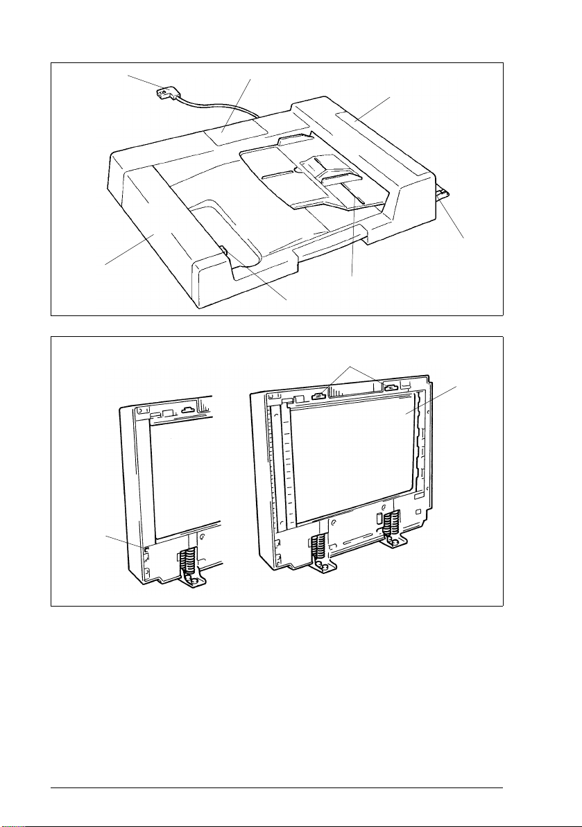
1.2 Components Identification
1
7
<AF-5> <AFR-12>
2
3
4
5
6
9
8
10
M-4AFR-12/AF-5 Rev. 1.0/05. 99
Page 9

1. Hookup Cord
2. Maintenance Cover
3. T a ke -Up Co ve r
4. Single Feed Tray
5. Document Feed Table
6. Turnover Cover Release Swit ch (AFR-12)
7. Turnover Cover (AFR- 12)
8. Transport Belt
9. Magnet Catches
10.Guide Plate Release Lever (AF-5)
Electrical
General/Mechanical
M-5 AFR-12/AF-5Rev. 1.0/05.99
Page 10
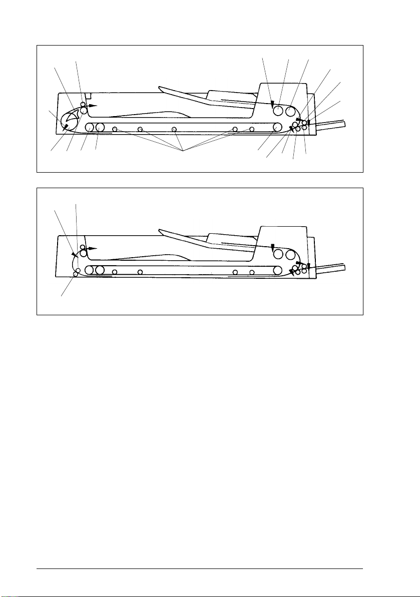
1.3 Cross-sectional View
19
18
<AFR-12>
1
2
3
4
5
17
16 15
21
20
22
14
13
12
<AF-5>
11
10
6
9
7
8
M-6AFR-12/AF-5 Rev. 1.0/05. 99
Page 11

1. Document Detecting Sensor (S1)
2. Document Take-Up Roller
3. Document Separator Roll er
4. Registration Sensor
5. Single Feed Transpor t Roller
6. Manual Feed Take-up Sensor (PWB-D)
7. Single Feed Transpor t Roll
8. Registration Driven Roller
9. Registration Drive Roller
10.Size Sensor
11.Transport Belt Drive Roller
12.Transport Rolls
13.Transport Belt Guide Roller
14.Transport Belt Driven Roller
15. Exit Ro lle r
16.Turnover Roller
17.Turnover/Exit Sensor
18.Turnover/Exit Switching Plate
19.Exit Roll
20.Exit Transport Roll
21.Exit Sensor (S3)
22.Exit Transport Roller
Electrical
General/Mechanical
M-7 AFR-12/AF-5Rev. 1.0/05.99
Page 12
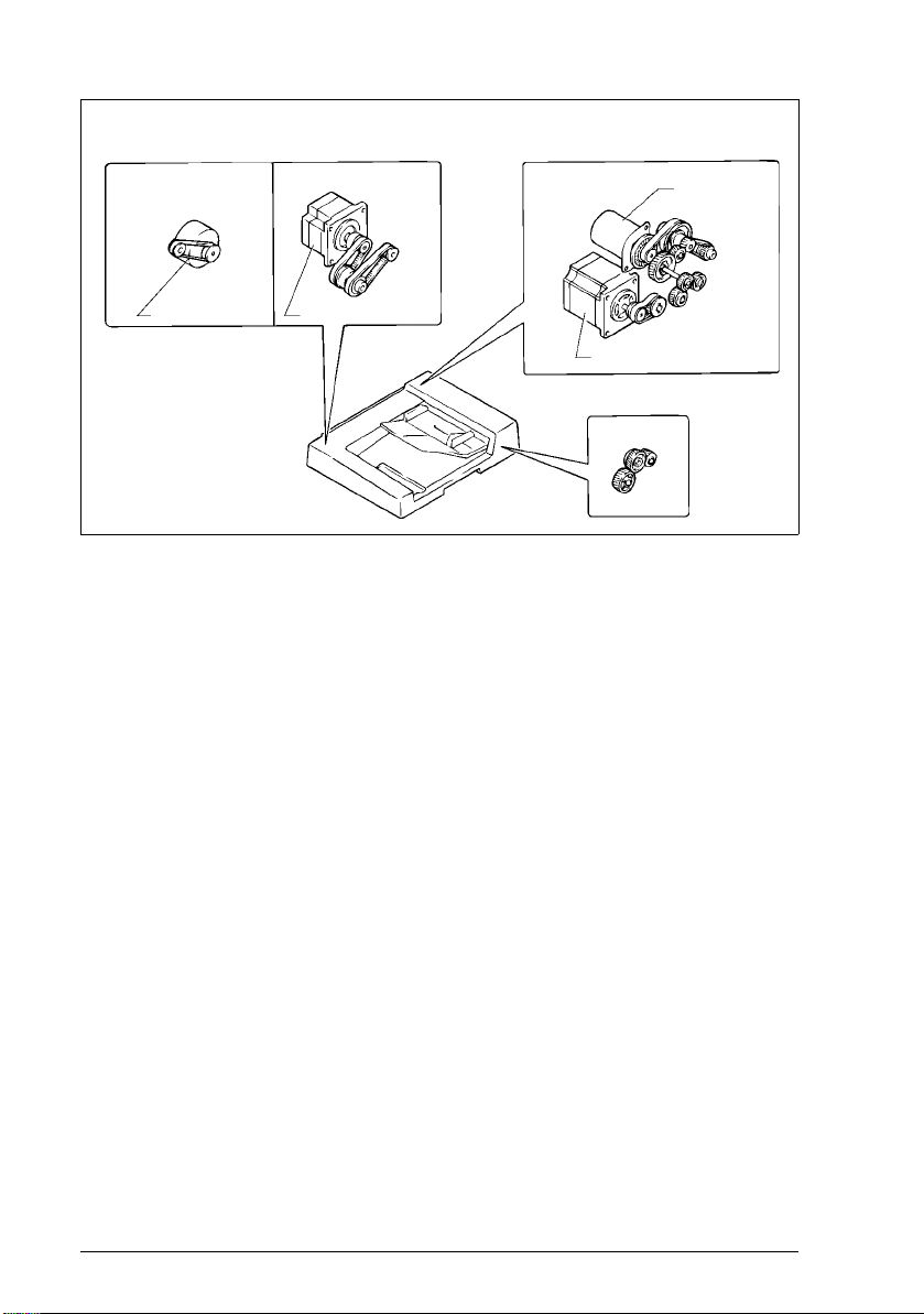
1.4 Drive System
Exit Mechanism
<AF-5>
Exit Motor (M3)
Turnover/
Exit Mechanism
<AFR-12>
Turnover/Exit Motor (M3)
Take-Up/
Transport Mechanism
Take-Up Motor (M1)
Transport Motor ( M2 )
Transport Belt Drive Mech anism
M-8AFR-12/AF-5 Rev. 1.0/05. 99
Page 13
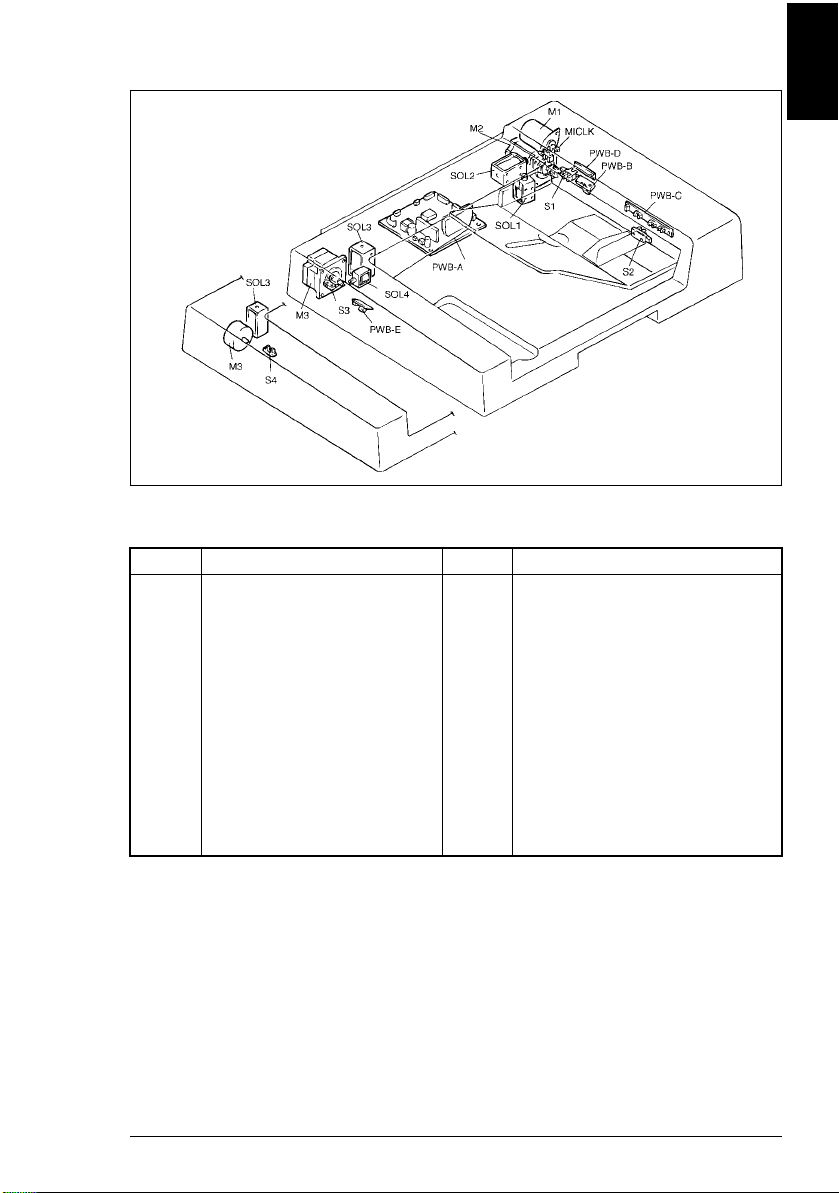
1.5 Electrical Component Layout
<AFR-12>
<AF-5>
Code Name Code Name
PWB-A
PWB-B
PWB-C
PWB-D
PWB-E
M1
M2
M3
M3
Main Control Board
Registration Sensor
Size Sensor
Manual Feed Take-up Sensor
Turnover/Exit Sensor
Take-Up Mot o r
Transport Motor
Turnover/Exit Motor (AFR-12)
Exit Motor (AF-5)
SOL1
SOL2
SOL3
SOL4
S1
S2
S3
S4
MICLK
Document Stopper Solenoid
Document Pressure Solenoid
Scale Solenoid
Turnover/Exit Switching Solenoid
Document Detecting Sensor
Feed Cover Set Switch
Turnover Cover Set Switch
Exit Sensor
Document Feed Motor Pulse Sensor
Electrical
General/Mechanical
M-9 AFR-12/AF-5Rev. 1.0/05.99
Page 14

1.6 Description Of Modes
1.6.1 Mixed Original Mode
● If the Mixed Orig key on the control panel is pressed when the copier is set
in 1- or 2-sided mode, or 2-in-1 mode, the copier detects the size of the
document each time a document is taken up and fed in. The copier feeds
the copy paper of a size selected from among the available paper sources
according to the document size detected.
1.6.2 1-Sided Original Mode
● When in this mode, the copier detects the size of the document which is
taken up and fed in first .
● The copier therefore needs to determine the size of the copy paper only
once based on the detec ted document size and the copying se tting made on
the control pane l. This makes for faster paper feed timing on the part of the
copier.
NOTE
If a set of documents of varying sizes are used in this mode, image trouble could
result including missing copy image. (The system does not force a misfeed
condition.)
1.6.3 2-Sided Mode
● The copier automatically turns over the 2-sided document for a speedy
copying operation (copies are made in the order of the first and second
pages).
1.6.4 2-in-1 Mode
● When in this mode, the copier positions two different documents on the
Original Glass side-by-side for making a copy of the two documents onto
one side of a single sheet of paper in a single copy run.
● If this mode is to be used for a set of documents of different widths, the
Mixed Orig key must first be pressed.
1.6.5 S-ADF (Single Feed) Mode
● When a single document is placed in the Single Feed Tray, the ADF
automatically takes it up and feeds it in to let the copier run a single copy
cycle.
NOTE
The ADF automatically takes up and feeds in documents even when two or more
documents are placed on the Single Feed Tray ; However, it could resul t in a double
feed or other faulty condition. Only one document should therefore be lo aded.
M-10AFR-12/AF-5 Rev. 1.0/05. 99
Page 15

1.6.6 Thin Mode (As set by "Original Thickness" of User’s M ode)
● When in this mode, the ADF transports the document at a low speed and
stops it without l etting it hit against the Original Width Scale.
Electrical
General/Mechanical
M-11 AFR-12/AF-5Rev. 1.0/05.99
Page 16
1.7 Document Take-up/feeding Mechanism
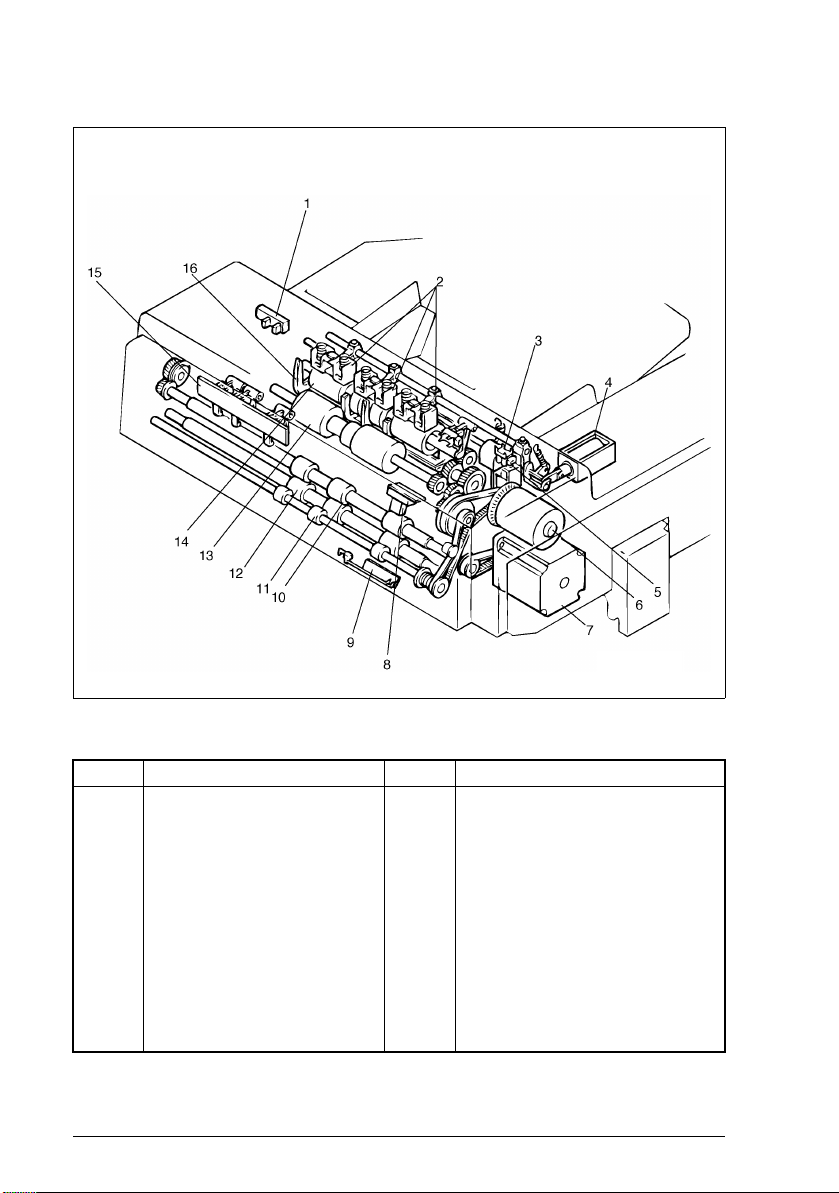
1.7.1 Construction
No. Name No. Name
1
Feed Cover Set Sensor (S2)
2
Document Pressure Pad
3
Document Feed Motor Pulse Sensor
(M1CLK)
4
Document Pressure Solenoid (SOL2)
5
Document Stopper Solenoid (SOL1)
6
Take-Up Motor (M1)
7
Transport Motor
8
Registration Sensor (PWB-B)
9
Manual Feed Take-up Sensor
(PWB-D)
10
Registration Drive Roller
11
Single Feed Transport Roller
12
Registration Driven Roller
13
Document Separator Roller
14
Document Take-Up Roller
15
Size Sens or (PWB-C)
16
Document Stopper Guide Plate
M-12AFR-12/AF-5 Rev. 1.0/05. 99
Page 17
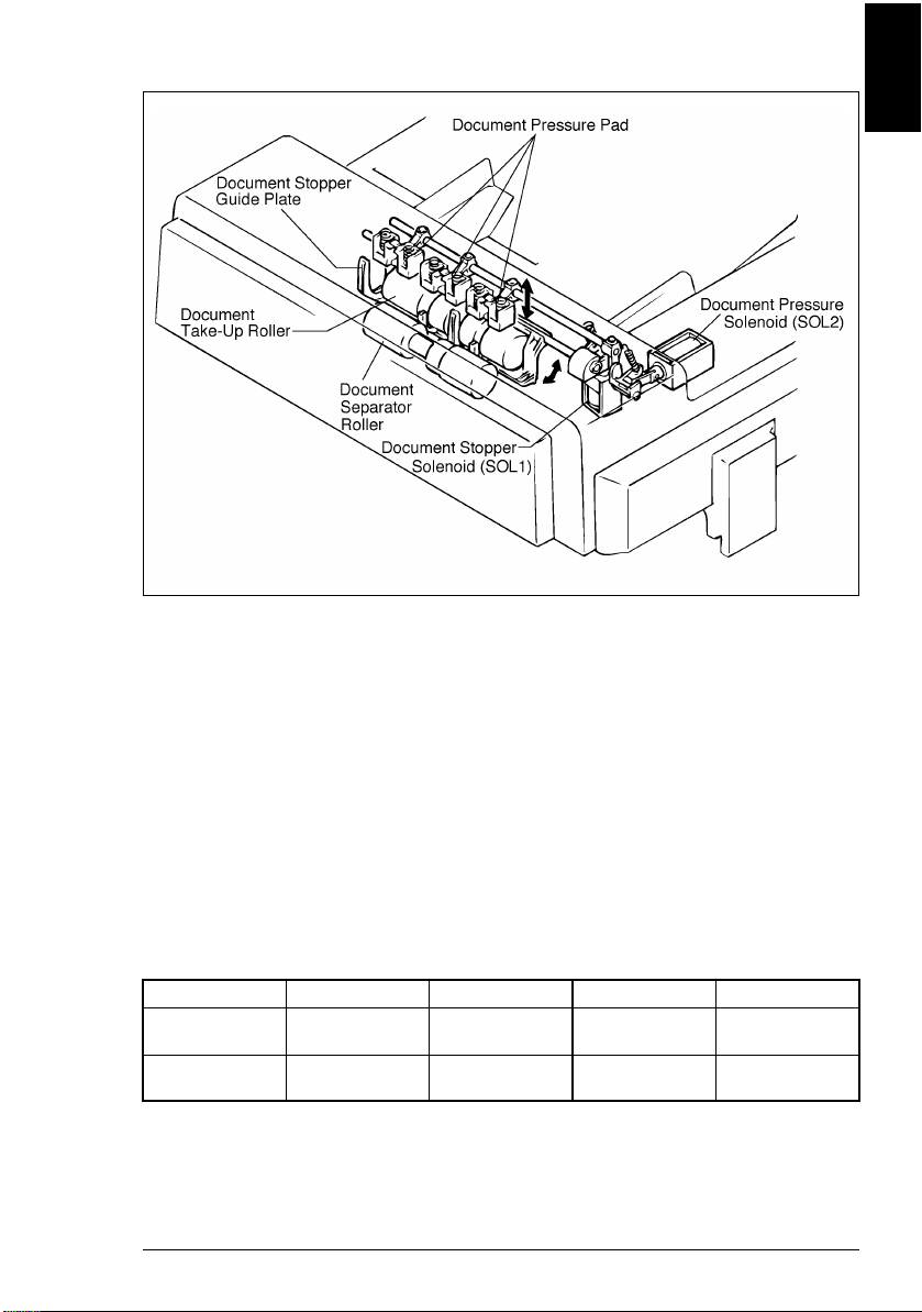
1.7.2 Document Pick-Up Mechanism
● The document pick-up mechanism consists of the Document Pressure
Pads, Document Stopper Guide Plate and Document Take-Up Roller.
● When documents are loaded on the document feed table, they are pressed
against the Document Take-Up Roller by the Document Pressure Pads,
then they are taken up by the Document Take-Up Roller one by one,
commencing with the one from the bottom of the stack.
● The Document Stopper Gu ide Pl ate det ermines t he leadi ng edge posi tio n of
the documents loaded in the ADF. It is normally in the raised position, and
is lowered at the star t of pi ck-up motion.
Electrical
General/Mechanical
SOL1/2 Control
SOL 1 and 2 are energized and de-energized by the signal output from IC3A on
PWB-A.
SOL1 IC3A-20 IC3A-21 SOL2 IC3A- 16
ON
(Stopper UP)
OFF
(Stopper DOWN)
HLONH
LHOFFL
M-13 AFR-12/AF-5Rev. 1.0/05.99
Page 18
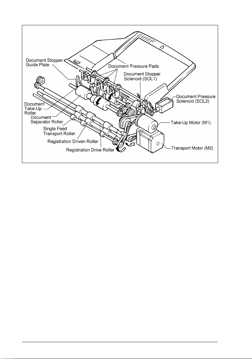
1.7.3 Document Take-Up Mechanism
● The document take-up m echanism takes up a document from the bottom of
a set of documents loaded on the Single Feed Tray and feeds it up to the
registration roller. It is drive n by the Take-Up Motor.
● The Take-Up motor (M1) rotates the Document Take-Up Roller, Document
Separator Roller and Single Feed Transport Roller via Gears, Pulleys and
Timing Belt.
M-14AFR-12/AF-5 Rev. 1.0/05. 99
Page 19
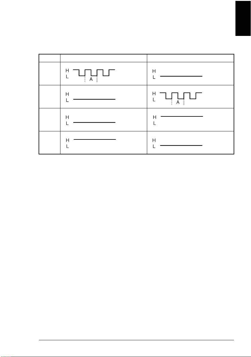
M1 Control
M1 is controlled by the following output signals. M1 speed is detected by the pulse
disk mounted on the motor output shaft and Document Feed Motor Pulse Sensor
(M1 CLK). M1 pulses are applied to IC1A-74, and period A is maintained at the
same length so that the motor rotates at a constant speed.
IC3 Forward Backward
Pin 65
(MIL1)
Pin 66
(MUL2)
Pin 67
(MIHI)
Pin 68
(MIL2)
Electrical
General/Mechanical
M-15 AFR-12/AF-5Rev. 1.0/05.99
Page 20
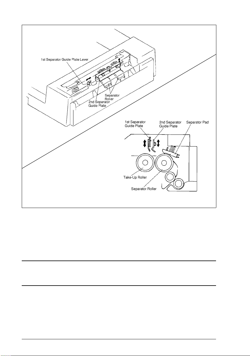
1.7.4 Separating Mechanism
● Movable Separator Guide Plates are used in the Document Separating
Mechanism. The height of the 1st and 2nd Separator Guide Plates can be
adjusted by a lever or screws, respectively.
● Lowering the Guide Plates can reduce the occurrence of Smudging on the
back of documents and smearing of the document image by reducing the
number of documents delivered of the Separator Roller.
NOTE
Both 1st an d 2n d Sep arator Guide Pla tes ha ve b een set i n the rais ed p ositi on at the
time of shipment from the factory.
● The Separator Pad is design ed t o be pr esse d aga inst the Sepa rator Rolle rs.
This ensures t hat documents ar e transport ed one by one even i f two or more
documents are fed fr om the Take-Up Roller.
M-16AFR-12/AF-5 Rev. 1.0/05. 99
Page 21
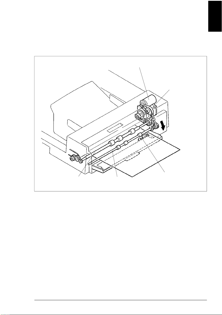
1.7.5 Sing le Feed M e chanis m
● The single feed mechanism is used to copy docum ents one at a time only.
● Open the Single Feed Tray and set a doc um ent in place. The Manual Feed
Take-up Sensor (PWB-D) will detect the document and the Single Feed
Transport Roller/Registration Roller begins to rotate to take up the
document automatically even if the Start key i s not pressed.
Take-Up Motor (M1)
Transport Motor (M2)
Electrical
General/Mechanical
Registration Drive
Roller
Single Feed
Transport Roller
M-17 AFR-12/AF-5Rev. 1.0/05.99
Manual Feed
Take - up Sens o r (P WB-D)
Page 22
1.8 Document Transport Mechanism
1.8.1 Construction
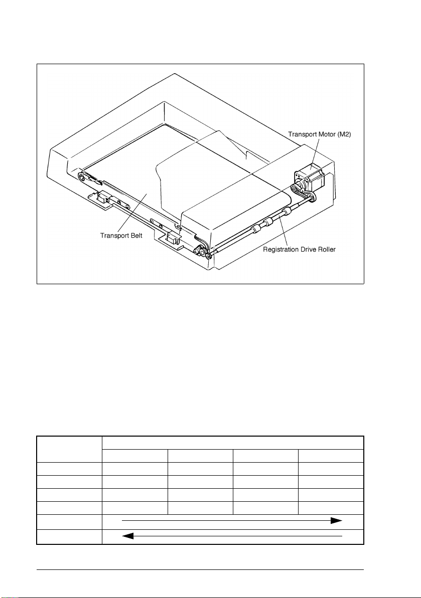
1.8.2 Document Transport Mec hanism
● The document transport mechanism transport the document, which has
been fed up to the Registration Roller from the document take-up
mechanism, up to the Original Width Scale by means of the Document
Transport Belt.
● During the turnover motion, the Document Transport Belt is turned to
transport the docum ent toward the take-up end.
M2 Control
Whether M2 is turned f orward or bac kward is det ermined by the combinat i on of the
following signals output from IC4 on PWB-A.
IC4
Pin 2 H H L L
Pin 3 L L H H
Pin 6 L H H L
Pin 7 H L L H
Forward Rotation
Backward Rotation
Step1 Step2 Step3 Step4
Procedure
M-18AFR-12/AF-5 Rev. 1.0/05. 99
Page 23
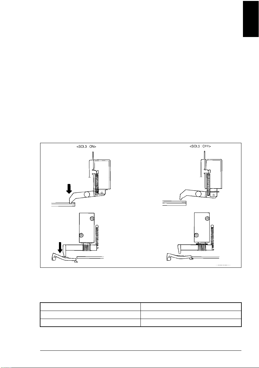
1.8.3 Original Width Scal e Retraction Mechanism
● When the document is positioned on the Original Glass by the ADF, the
leading edge o f the d ocument is p res sed agai nst th e Ori ginal Width Scale t o
improve positioning accuracy. During turnover and ejection motion,
however, the document must move over the Original Width Scale. For this
reason, the Orig inal Width Scale retraction mechanism is employed.
● Scale Solenoid SOL3 is used to drive the retraction mechanism.
<Operation>
When the document is positioned: SOL3 is de-energized and the Original
Width Scale i s rai sed by t he t ensio n of t he
Original Width Scal e Spring.
While the document is being
transported and during a copy cycle:
SOL3 is en ergi zed and the Original Width
Scale is pressed downward by the
Original Width Scale Drive Lever and
spring.
Electrical
General/Mechanical
SOL3 Control
The SOL3 is energized and de- energized by the signal output from IC3A on
PWB-A.
SOL3 IC3A-14
ON H
OFF L
M-19 AFR-12/AF-5Rev. 1.0/05.99
Page 24

1.9 Turnover/Exit Mechanism
1.9.1 Construction
<AF-5>
Exit
Transport Roller
Exit Motor (M3)
Exit
Roller
Scale Solenoid (SOL3)
Exit Sensor (S4)
M-20AFR-12/AF-5 Rev. 1.0/05. 99
Page 25

1.9.2 Turnover/Exit Docu men t Transport Mechanism
● The turnover/exit document transport mechanism turns over and ejects the
document which has been transported by the document transport
mechanism. It is driven by the Turnover/ Exit Motor (M3).
● M3 turns both the Turnover Roller and Exit Roller. These rollers are turned
in the same direction regardless of whether a document is turned over or
ejected from the ADF.
Electrical
General/Mechanical
M-21 AFR-12/AF-5Rev. 1.0/05.99
Page 26

M3 Control
Whether M3 is turned f orward or bac kward is det ermined by the combinat ion of t he
following signals output from IC13 or PWB-A.
<AFR-12>
IC13
Pin 2 HHHLLLLL
Pin 3 L L L L H H H L
Pin 6 LLHHHLLL
Pin 7 HLLLLLHH
Forward Rotation
IC13
Pin 2 H H L L
Pin 3 L L H H
Pin 6 L H H L
Pin 7 H L L H
Forward Rotation
Step1 Step2 Step3 Step4 Step5 Step6 Step7 Step8
Step1 Step2 Step3 Step4
Procedur
<AF-5>
Procedure
M-22AFR-12/AF-5 Rev. 1.0/05. 99
Page 27

1.9.3 Turnover/Exit Switchi ng M echanism (AFR-12)
● The turnover/exit switching mechanism uses the Turnover/Exit Switching
Plate which is swung downward or upward to change the document path,
thereby allowing the document to be turned over or ejected from the ADF.
This plate is actuat ed by the Turnover/Exit Swit ching Solenoid (SOL4).
SOL4 Control
The SOL4 is energized and de- energized by the signal output from IC3A on
PWB-A.
SOL4 IC3A-17
ON H
OFF L
Electrical
General/Mechanical
M-23 AFR-12/AF-5Rev. 1.0/05.99
Page 28

1.9.4 Exit Mechanism (AF-5)
● If a document misfeed occurs in the document path of the exit mechanism,
the Guide Plate Release Leve r may be pres sed downward usi ng the ti p of a
screwdriver or similar device, thereby raising the Guide Plate to allow the
user or Tech. Rep. to clear a document.
M-24AFR-12/AF-5 Rev. 1.0/05. 99
Page 29

1.10 Miscellaneous
1.10.1 Document Size Detection Mechanism
1. Width Detectio n
● The width of the document is detected by the sensor located on the Size
Sensor (PWB-C).
● The sensor is turned ON and OFF by actuator locat ed at point s approx. 268
mm respectively, from the Rear Document Guide.
2. Length Detection
● The length of the document is detected by the number of pulses generated
by the Transport Motor (M2) for the period in which the Registration Roller
starts turning and the tra il ing edge of the document passes the Registration
Sensor (PWB-B).
1.10.2 Raised/Lowered Position Detecting Mechanism
● DF Set Switch is located at the front left corner of the copier and a magnet
catch is mounted on the front left of the ADF. The position of the ADF,
whether rai sed or lowered, can be detected as the reed swi tch is turned ON
and OFF by the magnet catch.
● Opening/closing the ADF serves to reset a misfeed condition and allows
selection of a Test Mode operation.
Electrical
General/Mechanical
1.10.3
M-25 AFR-12/AF-5Rev. 1.0/05.99
Page 30

TEST MODES
Table Of Contents-1 AFR-12/AF-5Rev. 1.0/05.99
Page 31

2TEST MODES
2.1 Test Modes - - - - - - - - - - - - - - - - - - - - - - - - - - - - - - - 1
2.1.1 Paper Passage Check - - - - - - - - - - - - - - - - - - - - - - - - - - - - 2
2.1.2 Unit Check- - - - - - - - - - - - - - - - - - - - - - - - - - - - - - - - - - - - - 4
2.1.3 Sensor Check - - - - - - - - - - - - - - - - - - - - - - - - - - - - - - - - - - 7
2.1.4 Sensor Adjustment Check- - - - - - - - - - - - - - - - - - - - - - - - - - 9
Table Of Contents-2AFR-12/AF-5 Rev. 1.0/05. 99
Page 32

2TEST MODES
2.1 Test Modes
Test Modes
PSW1
SW1
ON
LED5
LED4
LED3
LED2
LED1
<Test Mode Setting Pr ocedure>
1. The test mode is initiated when the DIP switch (AW1-6) is set to ON with the
Main Switch of the copier set to OFF and then Main Switch is ON.
SW1-6
ON Test Mode
OFF Normal Mode
2. Various test modes are availa ble. They can be se lected by a combi nation of DIP
switches (SW1-1 to 1-6).
S-1 AFR-12/AF-5Rev. 1.0/05.99
Page 33

2.1.1 Paper Passage Check
1. With the Main Switch set to OFF, select the desir ed test mode as shown below.
Transport Speed
High-speed Mode OFF OFF –––ON
Medium-speed Mode ON OFF – – – ON
Low-speed Mode OFF ON – – – ON
123456
SW1
2. Select whether docum ents are to be fed continuously or intermittently.
Continuous Feed After the desired test mode is selected, turn the Main Switch ON.
Intermittent Feed While holding down PSW1, turn the Main Switch ON.
3. Select the plain paper mode or thin paper mode.
Test Mode SW1-3
Plain Paper OFF
Thin Paper ON
4. Select th e d esired test mod e fr om t he ta ble be lo w, the n o pen and cl ose t he ADF
to confirm the selection.
Tes t Mode
1-sided Non-mixed Mode (high-speed) OF F OFF – – – ON
1-sided Mixed Mode (normal) ON OFF – – – ON
2-sided Mode (AFR-12) OFF ON – – – ON
2-in-1 Mode OFF ON – – – ON
123456
SW1
* The following two modes are available to allow the user to check the actual
paper stop position by stopping the paper without allowing it to contact the
Original Width Scale and then raising the Scale. These modes are available
only when the plain paper mode is selected.
● 1-sided document
<Setting Method>
❍ Turn PSW1 ON with the ADF open, then close the ADF and carry out the
test.
● 2-sided document
<Setting Method>
❍ Turn PSW1 ON with the turnover cover open, then close the cover and
carry out the test.
S-2AFR-12/AF-5 Rev. 1.0/ 05.99
Page 34

(1) Flow of Paper Passage Test
Select the desired test mode.
Load a required number of sheets of paper on the Single
feed Tray, then turn PSW1 ON.
The selected test mode starts.
● Tu rning PS W1 ON d uring a test will interrup t the tes t.
Turning it ON agai n will ejec t all the she ets of paper and
terminate the test.
● In the case of the intermittent mode, the test is carried
out each time the PSW1 is turned ON.
(2) LED Status when the Copier is in Standby for Paper Passage Test
● Faulty sections are indicated as follows while the copier is in standby for a
paper passage test. If no fault is present, all the LEDs (LED1 to 4) will be
OFF.
Test Modes
LED
12345
◆❍❍❍●
❍◆❍❍●
❍❍◆❍●Turnover (AFR-12) cover set is faulty.
● : For monotoring ❍ : Not lit ◆ : Lit up
Take-up cover set is faulty.
ADF set is faulty.
Discription
NOTE
LED5 blinks at all ti m es.
S-3 AFR-12/AF-5Rev. 1.0/05.99
Page 35

2.1.2 Unit Check
1. Set SW1-6 to ON with the Main Switch set to OFF.
2. Turn the Main Switch ON, select the desir ed mode from the foll owing table, th en
open and close the ADF to conf ir m the sel ection.
Tes t Mode
Take-Up Motor Check OFF OFF ON OFF OFF OFF
Transport Motor Check ON OFF ON OFF OFF OFF
Exit Motor Check OFF ON ON OFF OFF OFF
Solenoid Check ON ON ON OFF OFF OFF
123456
SW1
3. Turn PSW1 ON to start the test.
–Take-Up Motor Check–
LED
12345
❍❍❍❍●
◆❍❍❍●
❍◆❍❍●
◆◆❍❍● 3 Backward rotation
● : For monotoring ❍ : Not lit ◆ : Lit up
Number of
Times PSW1
is Turned ON
0Stop
1 Forward rotation
2Stop
Operation
S-4AFR-12/AF-5 Rev. 1.0/ 05.99
Page 36

–Transport Motor Check–
LED
12345
❍❍❍❍●
◆❍❍❍●
❍◆❍❍●
◆◆❍❍●
❍❍◆❍●
◆❍◆❍●
❍◆◆❍●
◆◆◆❍●
❍❍❍◆●
◆❍❍◆●
❍◆❍◆●
◆◆❍◆●
● : For monotoring ❍ : Not lit ◆ : Lit up
Number of
Times PSW1
is Turned ON
0Stop
1
Forward rotation
2Stop
3
Backward rotation
4Stop
5
Medium-speed/
Forward rotation
6Stop
7
Medium-speed/
Backward rotation
8Stop
9
Forward rotation
10 Stop
11
Backward rotation
Operation
High-speed/
High-speed/
Low-speed/
Low-speed/
Test Modes
–Exit Motor Check–
LED
12345
❍❍❍❍●
◆❍❍❍●
❍◆❍❍● 2Stop
◆◆❍❍● 3
❍❍◆❍● 4Stop
◆❍◆❍● 5
❍◆◆❍● 6Stop
◆◆◆❍●
● : For monotoring ❍ : Not lit ◆ : Lit up
Number of
Times PSW1
Operation
is Turned ON
0Stop
1
High-speed/
Rotation
Medium-speed/
Rotation
Low-speed/
Rotation
7 Eject-speed
S-5 AFR-12/AF-5Rev. 1.0/05.99
Page 37

–Solenoid Check–
LED
12345
❍❍❍❍●
◆❍❍❍●
❍◆❍❍●
◆◆❍❍●
❍❍◆❍●
◆❍◆❍●
❍◆◆❍●
◆◆◆❍●
● : For monotoring ❍ : Not lit ◆ : Lit up
Number of
Times PSW1
is Turned ON
0Stop
1
2Stop
3
Medium-speed/
4Stop
5
6Stop
7 Eject-speed
Operation
High-speed/
Rotation
Rotation
Low-speed/
Rotation
S-6AFR-12/AF-5 Rev. 1.0/ 05.99
Page 38

2.1.3 Sensor Check
1. Set the SW1-6 to ON with the Main Switch set to OFF.
2. Turn the Main Switch ON, select the desire d mode from the foll owing table, the n
open and close the ADF to confirm the selection.
Te st M od e
Paper Passage Sensor OFF OFF OFF OFF OFF OFF
Cover Sensor ON OFF OFF OFF OFF OFF
Other Sensors OFF ON OFF OFF OFF OFF
123456
SW1
3. Block each sensor with a piece of paper etc. to check whether the
corresponding LED lights up.
NOTE
LED Status
Paper is present: Lit
No paper present: Not lit
– Paper Passage Sensor Check –
LD1: Document Detecting Sensor (S1)
LD2: Manual Feed Take-up Sensor (PWB-D)
LD3: Registrat ion Sensor (PWB-B)
LD4: Exit Sensor (S4): AF-5
Turnover/Exi t Sensor (PWB-E): AFR-12
Test Modes
– Cover Sensor Check –
LD1: Feed Cover Set Sensor (S2)
LD2: Size Reset Switch (S108)
LD3: Turnover Cover Set Swit ch (S3): AFR-12
S-7 AFR-12/AF-5Rev. 1.0/05.99
Page 39

– Other Sensors Check –
LD1: Size Sensor (Rear)
LD2: Size Sensor (Center)
LD3: Size Sensor (Front)
LD4: Document Feed Motor Pulse Sensor
(M1CLK)
NOTE
PWB-C
LD1, LD3 Japan Only
LD4 (Document Feed Motor Pulse Sensor) lights up when the sensor is blocked,
and goes out when the sensor is unblocked.
S-8AFR-12/AF-5 Rev. 1.0/ 05.99
Page 40

2.1.4 Sensor Adjustment Check
1. Set the SW1-6 to ON with the Main Switch set to OFF.
2. Turn the Main Switch ON, select the sensor adjustment mode as shown in the
following table, then open and close the ADF to confirm the selection.
Te st M od e
Sensor Adjustment
123456
ON OFF OFF ON OFF OFF
SW1
3. Turn the PSW1 ON to start the test.
NOTE
An error will oc cur if adjust ment is carr ied out with t he take- up/tur nover co ver open.
So make sure that the cover is closed before st arting adjustment.
– Registration Sensor Adjustment –
LED1 LED2 Sensor Status
❍❍
❍◆
◆❍
◆◆Adjustment complete
Initialized
Upper-limit error
Lower-limit error
– Exit Sensor Adjustm ent –
LED3 LED4 Sensor Status
❍❍
❍◆
◆❍
◆◆Adjustment complete
❍: Not lit
◆: Lit up
Initialized
Upper-limit error
Lower-limit error
Test Modes
2.1.5
S-9 AFR-12/AF-5Rev. 1.0/05.99
Page 41

DIS/REASSEMBLY/ADJUSTMENT
Table Of Contents-1 AFR-12/AF-5Rev. 1.0/05.99
Page 42

For the Utmost Safety
Warning
● For replacement parts, use the genuine parts with their part numbers
specified in the parts manual. Use of a wrong part could cause an overload
or dielectric breakdown, resulting in an electric shock or fire.
● Replace a blown fuse or thermal fuse with the corresponding genuine part
with its part number specified in the parts manual. Use of a fuse with a
different rating or one with the same rating but of a different type can result
in a fire. Especially when a thermal fuse blows frequently, the thermal
control system is probably faulty. Be sure to take necessary action.
● Before attempting to disassemble the machine, be sure to unplug its power
cord. The machine contains a high voltage unit and a circuit with a large
current capac ity that may cause an electri c shock or bur n from s parking. T he
machine also contains quick moving parts, which could injure a person. If
the machine uses a laser, a person can lose his/her eyesight by a laser
beam leak.
● Wherever feasible, keep the c over s and par ts m ounted when ener gizi ng the
machine. If it is absolutely necessary to energize the machine with its cover
removed, do not touch an exposed part that is being charged and use care
not to allow your clothing to be caught by a timing belt, gear, or other moving
part.
● Do not leave the machine unattended while it is being energized.
CAUTION
● To actuate an interlock switch with a cover removed or opened, be sure to
use the interlock switch actuating jig. Use of folded paper can damage the
interlock sw itch mechanism.
Table Of Contents-2AFR-12/AF-5 Rev. 1.0/05. 99
Page 43

CAUTION
● A high voltage is being a ppl ied to the par t marked wit h the sy mbol shown on
the right. Touching it can cause an electric shock. Be sure to unplug the
power cord when servic ing this part or other parts near it.
● When the machine is energized with any of its co ver s removed, ne ver use a
flammable spray near it, as a fire can result.
● Make sure that correct screws (diameter and length of the screw, binding/
tapping screws) are used in the correct places when assembling parts. If a
wrong screw is used, a short insulating distance could result. It could also
result in collapsed threads, which provides only a poor grounding
connection, resulting in an electr ic shock.
● A toothed washer and spring wash er, if used originally, must be reinstall ed.
If they are left out, a contact failure results, causing an electric shoc k or fire.
● Replace a lithium cell only with one having the part number specified in the
parts manual. An explosion could result if the cell is installed with wrong
polarity or a wrong cell is in stalled. Dispose of a used lithiu m cell according
to the appli cable local regulat ions. Never throw it away or abandon i t on the
user’s premises.
Other Precautions
● While the machine is being energized, do not unplug or plug in a connec tor
on a PWB or relay harness.
● Since the Magnet Roller of the Imaging Unit generates a strong magnetic
force, do not bring a CRT, watc h, floppy disk, or magnetic card near it.
● Use of an air gun or v acuu m generat es s tati c elect ricit y which can cause the
ATDC Sensor and associa ted pa rts to brea k down. Be sure the refor e to use
a blower brush or c loth to clean th ese parts. I f a unit is to be c leaned, be sur e
to remove the sens ors in advance.
● MOS lCs are susceptible to static electricity. When handling a PWB loaded
with MOS ICs, follow precautions given in “1-2. INSTRUCTIONS FOR
HANDLING THE PWBs WITH MOS ICs.”
● The PC Drum is highly delicate. When handling the PC Drum, follow the
precautions given in “1-3. HANDLING OF THE PC DRUM.”
● To reassemble, reverse the order of disassembly unless otherwise
specified.
● Note that replacement of a PWB may call for readjustments or resetting of
particula r it em s.
Table Of Contents-3 AFR-12/AF-5Rev. 1.0/05.99
Page 44

CAUTION
DANGER OF EXPLOSION IF BATTERY IS INCORRECTLY REPLACED.
REPLACE ONLY WITH THE SAME OR EQUIVALENT TYPE RECOMMENDED
BY THE MANUFACTURER. DISPOSE OF USED BATTERIES ACCORDING TO
THE MANUFACTURER’S INSTRUCTIONS.
ADVARSEL
LITHIUMBATTERI - EKSPLOSIONSFARE VED FEJLAGTIG HÅNDTERING.
UDSKIFTNING MÅ KUN SKE MED BATTERI AF SAMME FABRIKAT OG TYPE.
LEVÅR DET BRUGLE BAFFERI TILBAGE TIL LEVERANDOREN.
Table Of Contents-4AFR-12/AF-5 Rev. 1.0/05. 99
Page 45

3DIS/REASSEMBLY, ADJUSTMENT
3.1 Disassembly
3.1.1 Removal of the Document Transport Belt
● Push the lever to the left,, then snap of f the C clip to release the Belt assy.
● Hold the top of the Transport Belt Assy and tilt the Assy towards you to
remove it.
Adjustment
Dis/Reassembly
D-1 AFR-12/AF-5Rev. 1.0/05.99
Page 46

● Remove two screws as shown in the figure, then bend the Exit Roller side
toremove the Transport Belt.
3.1.2 Removal of the Document Take-Up Roller Assy
● Remove the Transport Belt , then remove the Cover and Document Stopper
Guide Plate to remove the Take-Up Roller Assy.
D-2AFR-12/AF-5 Rev. 1.0/05.99
Page 47

3.1.3 Removal of the Document Take-Up and Separator Rollers
● Snap off the four C clips, then remove the rollers one by one.
NOTE
Take care not to lose the two pins attached to the Document Take-Up Roller.
Adjustment
Dis/Reassembly
D-3 AFR-12/AF-5Rev. 1.0/05.99
Page 48

3.1.4 Removal of the Separator Pad
● Open the Single Feed Single Feed Tray and Feed Cover, then remove four
screws to remove the Feed Cover.
● Push each Separator Pad to slide it upwards and remove it.
D-4AFR-12/AF-5 Rev. 1.0/05.99
Page 49

3.1.5 Removal of the Document Take-Up Unit Assy
● Remove the Transport Belt.
● Remove the Maintenanc e Cover a nd un plug t he connec tor s fr om PWB-A a s
shown in the figure. Remove the Single Feed Tray.
● Remove the ADF from the copier, and place it on a table upside down.
● Remove the Cover.
● Remove five screws, open the Feed Cover and lift out the Document Take-
Up Unit Assy.
Adjustment
Dis/Reassembly
NOTE
When reinstalling the Document Take-Up Unit Assy, make sure that the Feed
Cover is open. Tighten the five screws lightly by hand, then tighten securely after
the ADF is reinstall ed on the copier.
D-5 AFR-12/AF-5Rev. 1.0/05.99
Page 50

3.1.6 Removal of the Turnover/E xit Assy (AFR-12)
● Remove the Transport Belt, Maintenance Cover and unplug the connectors
from PWB-A as shown in the figure.
● Open the Turnover/Exit Cover and remove the screw.
● Remove the Cover and grounding wire (black).
● Remove five screws, ope n the Tur nover/Ex it Cover an d l ift out th e Turnov er/
Exit Unit A ss y .
NOTE
When reinstalling the Turnover/Exit Unit Assy, make sure that the Turnover/Exit
Cover is open.
D-6AFR-12/AF-5 Rev. 1.0/05.99
Page 51

3.1.7 Removal of the Take-Up Moto r/Transport Motor Unit (AF- 5)
● Remove the Transport Belt.
● Remove the Cover and grounding wire (black).
● Remove five screws, unplug the connectors as shown in the figure, then
remove the Exit Unit Assy.
3.1.8 Removal of the Take-Up Moto r/Transport Motor Unit
● Remove the Take-Up Unit Assy.
● Remove three screws, unplug from connectors, take out two wire saddles
and a spring to remove the Motor Unit.
Adjustment
Dis/Reassembly
D-7 AFR-12/AF-5Rev. 1.0/05.99
Page 52

3.2 Adjustments
3.2.1 Adjustment of Magnet Height NOTE
Requirement
The clearance between the Magnetic Catch and Original Glass should be
0 to 0.5 mm.
1. Remove the Transport Belt and two Screw Covers. (Push up from inside)
2. Set the Transp ort Bel t and, close the ADF, loo sen the Magn etic Catc h adjust ing
screws, check the clearance of the Magnet Catch, then tighten the adjusting
screws.
D-8AFR-12/AF-5 Rev. 1.0/05.99
Page 53

3.2.2 Adjustment of the Document Feed Table NOTE
Requirement
The document Feed Table s hould be positioned within 0 +/- 1 mm fr om the edge of
the Document Positi oning Plate.
1. Slide the Document Positioning Plate towards t he rear and secure it with tape.
2. Affix a piece of tape to each of the Magnet Catch Plates.
3. Place a document on the Document Feed Table and select 1-sided mode.
4. Press the Start key , th en press the Stop key immediately.
5. Open the ADF gently and remove the tape from the Document Positioning
Plate, taking care not to allow the document to move.
6. Check whether the document is aligned with the edge of the Document
Positioning Plat e.
7. If the document is off in direction "a", move the Document Feed Table towards
you. If the document is off in direction "b", move the Document Feed Table
towards the rear.
Adjustment
Dis/Reassembly
D-9 AFR-12/AF-5Rev. 1.0/05.99
Page 54

3.2.3 Adjustment of the Singl e Feed Tray NOTE
Requirement
The document Feed Table should be positioned within +/- 1 mm from the edge of
the Document Positi oning Plate.
1. Slide the Document Positioning Plate towards the rear and secure it with tape.
2. Affix a piece of tape to each of the Magnet Catch Plates.
1. Place a document on the Docum ent Feed Table and select 1-side d mode .
2. Press the Start key, t hen press the Stop key immediately.
3. Open the ADF gently and remove the tape from the Document Positioning
Plate, taking care not to allow the document to move.
4. Check whether the document is aligned with the edge of the Document
Positioning Plate.
5. If the document is off in direction "a", move the Single Feed Tray towards you.
If the document is off in direction "b", move the Single Feed Tray towards the
rear.
a
b
D-10AFR-12/AF-5 Rev. 1.0/05.99
Page 55

3.2.4 Adjustment of Document Stop Position in the 1-Sided Mode NOTE
Requirement
The document should be 0 to 1 mm in the direction of b from the end face of the
Original Widt h Scale.
1. Set "U-4" (Lightweight Original) of User’s Choice to "1." (Make the adjustment
in the Lightweight Original mode.)
NOTE: Metric areas only
2. Slide the Document Positioning Plate towards t he rear and secure it with tape.
3. Affix a piece of tape to each of the Magnet Catch Plates.
Adjustment
Dis/Reassembly
4. Place a document on the Document Feed Table, and select
1-sided original/1-sided copy mode.
5. Press the Start key , th en press the Stop key immediately.
6. Open the ADF gently and check whether t he documen t is aligne d with the edg e
of the Original Glass.
7. Set the service cho ice mode "c-31".
8. Referring to page D-17, adjust the document stop position.
a b
D-11 AFR-12/AF-5Rev. 1.0/05.99
Page 56

3.2.5 Adjustment of Document Stop Position in the 2-Sided Mode NOTE
Requirement
The document should be 0 to 1 mm in the direction of b from the end face of the
Original Widt h Scale.
1. Set "U-4" (Lightweight Original) of User’s Choice to "1." (Make the adjustment
in the Lightweight Original mode.)
NOTE: Metric areas only
2. Slide the Document Positioning Plate towards the rear and secure it with tape.
3. Affix a piece of tape to each of the Magnet Catch Plates.
4. Place a document on the Document Feed Table, and select 2-sided original/1-
sided copy mode.
5. Press the Start key, t hen press the Stop key immediately.
6. Open the ADF gently and chec k whether t he documen t is aligne d with the edge
of the Original Glass.
7. Set the service choice mode "c-32".
8. Referring to page D-17, adjust the document stop position.
a
b
D-12AFR-12/AF-5 Rev. 1.0/05.99
Page 57

3.2.6 Adjustment of Document Stop Position in the 2-in-1 Mode NOTE
Requirement
The document should be 0 to 1 mm in the direction of b from the end face of the
Original Widt h Scale.
1. Set "U-4" (Lightweight Original) of User’s Choice to "1." (Make the adjustment
in the Lightweight Original mode.)
NOTE: Metric areas only
2. Slide the Document Positioning Plate towards t he rear and secure it with tape.
3. Affix a piece of tape to each of the Magnet Catch Plates.
Adjustment
Dis/Reassembly
4. Place two A4Y documents on the Document Feed Table, and select
1-sided original/1-sided 2-in- 1 copy m ode.
5. Press the Start key , th en press the Stop key immediately.
6. Open the ADF gently and check whether t he documen t is aligne d with the edg e
of the Original Glass.
7. Set the service cho ice mode "c-33".
8. Referring to page D-17, adjust the document stop position.
ba
D-13 AFR-12/AF-5Rev. 1.0/05.99
Page 58

3.2.7 Adjustment of Distance Between Documents in the 2-in-1 Mode NOTE
Requirement
The second document should be 0 to 1 mm in the direction of b from the trailing
edge of the first document.
1. Set "U-4" (Lightweight Original) of User’s Choice to "1." (Make the adjustment
in the Lightweight Original mode.)
NOTE: Metric areas only
2. Slide the Document Positioning Plate towards the rear and secure it with tape.
3. Affix a piece of tape to each of the Magnet Catch Plates.
4. Place two A4Y documents on the Document Feed Table, and select
1-sided orig inal/1-sided 2-in-1 copy m ode.
5. Press the Start key, t hen press the Stop key immediately.
6. Open the ADF gently and check whether the 2nd document is positioned
correctly in relation with the 1st document.
7. Set the service choice mode "c-34".
8. Referring to page D-17, adjust the document stop position.
ab
D-14AFR-12/AF-5 Rev. 1.0/05.99
Page 59

3.2.8 Adjustment of Document Stop Position in the Single Feed Mode NOTE
Requirement
The document should be 0 to 1 mm in the direction of b from the end face of the
Original Widt h Scale.
1. Set "U-4" (Lightweight Original) of User’s Choice to "1." (Make the adjustment
in the Lightweight Original mode.)
NOTE: Metric areas only
2. Slide the Document Positioning Plate towards t he rear and secure it with tape.
3. Affix a piece of tape to each of the Magnet Catch Plates.
Adjustment
Dis/Reassembly
4. Place a document into the Manual Feed Port, and press the Stop key
immediately.
5. Open the ADF gently and check whether t he documen t is aligne d with the edg e
of the Original Glass.
6. Set the service cho ice mode "c-37".
7. Referring to page D-17, adjust the document stop position.
ba
D-15 AFR-12/AF-5Rev. 1.0/05.99
Page 60

3.2.9 Adjustment of ADF Registrati on Loop
1. Place a document on the Docum ent Feed Table and press the Start key .
2. Change the setting for service choice "c-38", rem ove the document and place it
on the Document Feed Table agai n, then press the Start key.
3. Referring to the table below, repeat steps 1 and 2 until the document is
positioned so that it can be transported by the Transport Belt.
Setting Method
1. Press the “Stop” , “0 ”, “Stop”, “1”, “2” keys in tha t order.
2. Select the desi red mode, then press the Start key.
3. Press the Clear key to clear the currently selected value.
4. Referring to the table below, enter a setting equi valent to the deviation .
5. Press the Start key to conf irm the entry.
6. Press the Reset key twi ce to return to the main screen.
Stop Position Adjustment Table
Setting
Deviatio
n (mm)
43 7
44 6 52 2
45 5 53 3
46 4 54 4
47 3 55 5
48 2 56 6
49 1 57 7
50 0 Default 58 8
Direction Setting
Moves in direction "a"
(towards the Original Width
Scale )
51 1
Deviatio
n (mm)
Direction
Moves in direction "b"
(towards the Take-Up
Mechanism)
D-16AFR-12/AF-5 Rev. 1.0/05.99
Page 61

3.2.10 Adjustment of Document Stopper Solenoid SOL1
1. Remove the Document Tak e-Up Unit Ass y and place i t on a table upsi de down.
2. Loosen two screws and bring the brush (marked "A" in the figure) of the
Document Stopper Guide Plate into contact with the Take-Up Roller.
3. While pressing the Document Stopper Guide Plate against the Take-Up Roller
gently, lift the solenoid by holding the two screws until it comes to a stop, then
tighten the scr ews.
Adjustment
Dis/Reassembly
NOTE
After comple tion o f adju st ment, l ift the Docu ment Stopper Guid e Plate to che ck t hat
the Guide Plate is supported smoothly by the retaining force of the solenoid.
D-17 AFR-12/AF-5Rev. 1.0/05.99
Page 62

3.2.11 Adjustment of Document Pressu re Solenoid SOL2 NOTE
Requirement
The clearanc e be tween t he Gui de Pla te and Weigh t Lever s hould be app roximat ely
2 ± 1 mm.
1. Remove the Document Take -Up Unit Assy, and place it on a table.
2. Loosen two screws.
3. While pushing t he Plunger towards the Soleno id (up to the posi tion at which t he
Plunger stops), move the Solenoid so that the clearance between the Guide
Plate and Weight Lever is within the specified range.
NOTE
When moving the Solenoid, make sure that the Plunger is pushed towards the
Solenoid and that there is no play between the Plunger and Weight Lever.
D-18AFR-12/AF-5 Rev. 1.0/05.99
Page 63

3.2.12 Adjustment of Scale Solenoid SOL3 NOTE
Requirement
The exposed end of the Stopper Lever is positioned within approximately
8.7 ± 0.2 mm in length.
1. Remove the Turnover/Exit Unit Assy and place it on a table upside down.
2. Loosen two screws.
3. Move the Solenoid up and down so that the exposed end of the Stopper Lever
is within the speci fied length.
4. Tighten the two scr ews.
Adjustment
Dis/Reassembly
D-19 AFR-12/AF-5Rev. 1.0/05.99
Page 64

3.2.13 Adjustment of Turnover/Exit Switching Solenoid SOL4 (AFR-12)
1. Remove the Turnover/Exit Unit Assy and place it on a table.
2. With sponge fitted to the Turnover/Exit Cover in contact with the Turnover/Exit
Switching Plate, move t he solen oid to t he right and lef t to obt ain a cl earance " 0"
at part A shown in the figure, move the solenoid to the right or left so that the
gap indicated by "A" in the figure is eliminat ed.
3. Tighten the two scr ews.
Sponge
A
D-20AFR-12/AF-5 Rev. 1.0/05.99
Page 65

3.2.14 Adjustment of the Separat ing Pressure of Document Separ ator Pad
1. Remove the Take-Up Unit Cover.
2. Loosen each screw and tig hten it to an appropriate level.
NOTE
Make sure that the separating pressure of bot h pads is the same.
Adjustment
Dis/Reassembly
D-21 AFR-12/AF-5Rev. 1.0/05.99
Page 66

3.2.15 Adjustment of the Distance bet w een Separator Rollers
1. Open the Take-Up Cover and loosen the four screws of the Separator Guide
Plate.
2. Cut out a piece of paper of approx. 150 mm by 50 mm and place it between the
Guide Plate and Roller.
3. While gently holding down the Separator Guide Mount Plate (press the Guide
as strongly as th e spri ng pressure), tighten the two screws to the Mount Plate.
4. Tighten the two screws that secure 2nd Separator Guide Plate in position.
5. Loosen the two screws on the 2nd Separator Guide Plate Mount Plate. Raise
the mount plate as far a s it will go and, keeping the m ount plate in that position,
tighten the two screws.
6. Loosen the two scr ews that secur e 2nd Separator Gui de Plate in po sition. Rais e
the guide plate as far as it will go and, keeping the plate in that position, tighten
the two screws.
3.2.16
Separator Guide Plate
2nd Separator Guid e Plat e
D-22AFR-12/AF-5 Rev. 1.0/05.99
Page 67

TROUBLESHOOTING
Table Of Contents-1 AFR-12/AF-5Rev. 1.0/05.99
Page 68

4TROUBLESHOOTING
4.1 Misfeed Detec ti o n - - - - - - - - - - - - - - - - - - - - - - - - - - 1
4.2 Troubleshooting Procedure- - - - - - - - - - - - - - - - - - - 2
Table Of Contents-2AFR-12/AF-5 Rev. 1.0/05. 99
Page 69

4TROUBLESHOOTING
4.1 Misfeed Detec ti o n
Misfeed at the ADF Take-Up/Single Feed Section
Description Detection Timing
Document not reaching
Registration Sensor (PWB-B)
Take-Up Motor (M1) malfunction Document Feed Pulse Sensor (M1CLK) is not activated within
PWB-B is not activated within approx. 1 sec. after Take-Up Motor
(M1) is energized.
approx. 0.2 sec. after M1 is energized.
Misfeed at the Transport Section
Description Detection Timing
Document staying at Registration
Sensor (PWB-B)
Document staying on Glass (before
operation)
Document staying on Glass (after
operation)
Misfeed at the Turnover/Exit Section (AFR-12 only)
Description Detection Timing
Document not reaching Exit Sensor
(PWB-E) (during ejection/turnover)
Document staying at PWB-E
(during ejection)
Document staying at PWB-E
(during turnover)
Description Detection Timing
Document not reaching Exit Sensor
(S4)
Document staying at S4 S4 is not deactivated within approx. 3 sec. after S4 is activated.
PWB-B is not activated even if the next document has reached the
scan position.
A sensor indicates that there is still a document in the document
path when the next document is placed on the Document Feed
Table and all covers are closed.
Exit Sensor (PWB-E: AFR/12, S4: AF-5) is activated when a 1st
document is taken up and fed in.
S4 is not activated within approx. 0.5 sec. after Turnover/Exit Motor
(M3) is energized.
PWB-E S4 is not deactivated within approx. 2 sec. after PWB-E is
activated.
PWB-E S4 is not deactivated within approx. 2 sec. after PWB-E is
activated.
Misfeed at Exit Section (AF-5 only)
S4 is not activated within approx. 0.7 sec. after Turnover/Exit Motor
(M3) is energized.
Troubleshooting
T-1 AFR-12/AF-5Rev. 1.0/05.99
Page 70

4.2 Troubleshooting Procedure
T-2AFR-12/AF-5 Rev. 1.0/05. 99
Page 71

Mis-feed at the ADF Take-Up Section
Symptom Step No. Check Item Result Action
● The document is
not taken up at all.
1 Does the document used
meet the specifications for
reliable feeding?
2 Has the capacity of the
Document Feed Table been
exceeded?
3 A re any of the Document
Take-Up Rollers, Document
Separator Rollers and
Document Separator Pads
deformed, worn or dirty with
paper dust?
Carry out the unit test for the
4
Document Pressure
Solen oid (S OL2) to check
whether it functions
properly.
5 Does the voltage across
CN9-2 on PWB-A and GND
change from 24 VDC when
the Start key is pressed?
6 Carry out the unit test for the
Document Stopper Solenoid
(SOL1) to check whether it
functions properly.
7 Does the voltage across
CN12-3 on PWB-A and
GND change from 24 VDC
to 0 VDC
instantaneously and then
return to 24 VDC when the
Start key is pressed?
Carry out the unit test for the
8
Document Feed Motor
Pulse Sensor (M1CLK) to
check whether it functions
properly.
9 Does the voltage across
CN5-3 on PWB-A and GND
change to "H" when M1CLK
is blocked and change to "L"
when M1CLK is unblocked,
when the pulse disk is
turned by hand?
10 Carry out the unit test for the
Take-Up Motor (M1) to
check whether it functions
properly.
11 Does the voltage across
CN6-1 on PWB-A and GND
change from 24 VDC when
the Start key is pressed?
NO Instruct the user to use
documents that meet the
specifications for reliable
feeding.
YES Instruct the user not to exceed
the capacity.
YES Clean or replace them.
YES Carry out step 6.
YES Replace SOL2.
NO Replace PWB-A.
YES Carry out step 8.
YES Replace SOL1.
NO Replace PWB-A.
YES Carry out step 10.
YES Replace PWB-A.
NO Rep lace.
YES Check each gear for damage.
YES Replace M1.
NO Replace PWB-A.
Troubleshooting
T-3 AFR-12/AF-5Rev. 1.0/05.99
Page 72

Mis-feed at the ADF Take-Up Section
Symptom Step No. Check Item Result Action
● The panel
indicates a
misfeed in the
ADF when the
Start key is
pressed, though
no documents are
placed on the
Document Feed
Table.
● The document is
not taken up in
single feed mode.
1
Does the actuator of the
Document Detecting Sensor
(S1) function properly?
2 Carry out the unit test for S1
to check whether it functions
properly.
3 Does the voltage across
CN3-12 on PWB-A and
GND change from 5 VDC to
0 VDC when the actuator is
lifted by hand?
1 Does the actuator of the
Manual Document Detecting
Sensor (PWB-D) function
properly?
2 Carry out the unit test for
PWB-D to check whether it
functions properly.
3 Does the voltage across
CN5-9 on PWB-A and GND
change from 5 VDC to 0
VDC when the light is
blocked with a piece of
paper?
4 Is the tension of the Timing
Belt correct and the Manual
Feed Transport Roller
clean?
NO Repair or replace the actuator.
YES Check the copier.
YES Replace PWB-A.
NO Replace S1.
NO Repair or replace the actuator.
YES Go to step 4.
YES Replace PWB-A.
NO Replace PWB-D.
YES Adjust the tension and clean or
replace the Roller.
T-4AFR-12/AF-5 Rev. 1.0/05. 99
Page 73

Mis-feed at the ADF Transport Section
Symptom Step No. Check Item Result Action
● The document has
stopped near the
Registration
Roller.
1 Does the document used
meet the specifications for
reliable feeding?
2 Is the Registration Roller
deformed, worn or dirty?
3 Are there any problems
along the document path
between the Registration
Roller and Transport Belt?
4 Is the Transport Belt
installed properly?
5 Is the Transport Belt
deformed, worn or dirty?
6 Carry out the unit test for the
Registration Sensor (PWBD) to check whether it
functions properly.
7 Does the voltage across
CN5-5 on PWB-A and GND
change from "H" to "L" when
the light is blocked with a
piece of paper?
8 Is the tension of the Timing
Belt correct?
NO Instruct the user to use
documents that meet the
specifications for reliable
feeding.
YES Clean the Registration Roller.
YES Clean, repair or replace the
transport path.
NO Install it properly.
YES Clean or repair the Belt.
YES Go to step 8.
YES Replace PWB-A.
NO Replace PWB-B.
NO Adjust the tension of the
Timing Belt.
Troubleshooting
T-5 AFR-12/AF-5Rev. 1.0/05.99
Page 74

Mis-feed at the ADF Transport Section
Symptom Step No. Check Item Result Action
● The document is
caught by the
Original Width
Scale.
● The document has
slipped between
the Original Glass
and Original Width
Scale.
● The document
gets caught
behind the
Transport Belt (2sided mode).
1 Does the document used
meet the specifications for
reliable feeding?
2
When the Original Width
Scale is pushed and
released by hand, does it
return to the correct position
by the force of the spring?
3 Carry out the unit test for the
Scale Solenoid (SOL3) to
check whether it functions
properly.
4 After start of transport, does
the voltage across CN4-2 of
PWB-A and GND change
from "H" to "L"?
5 Is the Transport Belt
NO Instruct the user to use
documents that meet the
specifications for reliable
feeding.
NO Check the mount position of
the spring at the bottom of the
Original Width
Scale. Replace the spring.
YES Go to step 5.
YES Replace SOL3.
NO Replace PWB-A.
YES Clean or replace it.
deformed, worn or dirty?
● The document has
stopped near the
Exit Sensor (S4).
● The document has
stopped near the
Turnover/Exit
Sensor (PWB-D).
(AFR-12)
1 Carry out the unit test for S4
to check whether it functions
properly.
2 Does the voltage across
CN4-5 on PWB-A and GND
change from 5 VDC to 0
VDC when S4 is blocked
with a piece of paper?
3 Is the Exit Roller deformed,
worn or dirty?
1 Carry out the unit test for
PWB-D to check whether it
functions properly.
2 Does the voltage across
CN11-6 on PWB-A and
GND change from "H" to "L"
when PWB-D is blocked
YES Go to step 3.
YES Replace PWB-A.
NO Replace S4.
YES Clean or replace it.
YES Go to step 3.
YES Replace PWB-A.
NO Replace PWB-D.
with a piece of paper?
3 Is the Turnover/Exit Roller
deformed, worn or dirty?
YES Clean.
T-6AFR-12/AF-5 Rev. 1.0/05. 99
Page 75

Misfeed Detected When Documents are Loaded
Symptom Step No. Check Item Result Action
● The panel
indicates a
misfeed in the
ADF when a
document is
placedon the
Document Feed
Table.
1 Is there still a document in
the ADF?
2 Carry out the unit test for the
Registration Sensor (PWBB) to check whether it
functions properly.
3 Does the voltage across
CN5-5 on PWB-A and GND
change from "H" to "L" when
the light is blocked with a
piece of paper?
4 Carry out the unit test for the
Size Sensor (PWB-C) to
check whether it functions
properly.
5 Does the voltage across
CN3-3, 3-4 and 3-5 on
PWB-A and GND change
from 5 VDC to 0 VDC when
the light is blocked with a
piece of paper?
6 Does the actuator of PWB-C
operate properly?
YES Remove the document.
YES Go to step 4.
YES Replace PWB-A.
NO Replace PWB-B.
YES Go to step 6.
YES Replace PWB-A.
NO Replace PWB-C.
YES Repair or replace the actuator.
4.3
Troubleshooting
T-7 AFR-12/AF-5Rev. 1.0/05.99
 Loading...