

Page 1

AD-7
SERVICE MANUAL
Page 2

CONTENTS
GENERAL, MECHANICAL/ELECTRICAL
1. SPECIFICATIO N S. . . . . . . . . . . . . . . . . . . . . . . . . . . . . . . . . . . . . . M-1
2. PARTS IDENTIFICATION. . . . . . . . . . . . . . . . . . . . . . . . . . . . . . . . M-2
3. CROSS-SECTIONAL VIEW . . . . . . . . . . . . . . . . . . . . . . . . . . . . . . M-3
4. DRIVE SYSTEM . . . . . . . . . . . . . . . . . . . . . . . . . . . . . . . . . . . . . . . M-4
5. ELECTRICAL COMPONENTS LAYOUT . . . . . . . . . . . . . . . . . . . . M-5
6. DESCRIPTION OF EACH MECHANISM AND CONTROL
6-1. Exit/Turnover Switching Mechanism . . . . . . . . . . . . . . . . . . . M-6
6-2. Fuser Oil Cleaning Mechanism. . . . . . . . . . . . . . . . . . . . . . . . M-6
6-3. Paper Standby Control . . . . . . . . . . . . . . . . . . . . . . . . . . . . . . M-6
6-4. Switchback Operation (Turnover). . . . . . . . . . . . . . . . . . . . . . M-7
7. OPERATION AND CONTROL
7-1. No. of Multiple 2-Sided Copies . . . . . . . . . . . . . . . . . . . . . . . . M-8
7-2. Sensor Locations . . . . . . . . . . . . . . . . . . . . . . . . . . . . . . . . . . . M-8
7-3. 2-Sided Copying Operation. . . . . . . . . . . . . . . . . . . . . . . . . . . M-10
DIS/RE ASSE MBL Y, ADJ USTM EN T
1. DISASSEMBLY
1-1. Removal of the Exterior Covers and Guides . . . . . . . . . . . . . D-1
1-2. Removal of Vertical Transport Clutch CL1. . . . . . . . . . . . . . . D-2
1-3. Removal of the Vertical Transport Roller (Metallic One) . . . D-3
1-4. Removal of the Vertical Transport Roller (Rubber One). . . . D-3
1-5. Removal of the Turnover Entrance Guide . . . . . . . . . . . . . . . D-4
2. ADJUSTMENTS
2-1. Adjustment of Dup. Left-Margin . . . . . . . . . . . . . . . . . . . . . . . D-4
2-2. Adjustment of Exit/Turnover Switching Solenoid SL1. . . . . . D-5
TROUBLESHOOTING
1. MISFEED DETECTION
1-1. Misfeed Detection Conditions . . . . . . . . . . . . . . . . . . . . . . . . . T-1
1-2. Misfeed Troubleshooting Procedures. . . . . . . . . . . . . . . . . . . T-2
APPENDED DIAGRAMS
◆
ELECTRICAL WIRING DIAGRAM / ELECTRICAL CIRCUIT DIAGRAM
i
Page 3

GENERAL,
MECHANICAL/
ELECTRICAL
Page 4

SPECIFICATIONS
1
Type : Sheet turnover device for making automatic
2-sided copies
Instal la t i on : Mounte d to t he co pi e r
Modes : Exit mode
Duplex mode (single- and two-sheet paper
attraction)
Max. Storage
Capacity
Exit Tray Capacity : 250 sheets of 90-g/m
Registration : Center
Power Source : DC24V ( supplied from copier)
Power Consumption : 30W or le ss
Dimensions : Width .....121 mm or 4-3/4"
Weight : 8.9 kg or 19-1/2 lbs. (including the mount)
Environmental
Requirements
Paper Requirements
- Exit mode Type of Paper : Recommended paper weighing 60 to 90 g/m
Paper Si ze : A5 lengt h w ise to A3 lengt hwi s e and A3 Wide or
- Duplex mode Type of Paper : Recommended paper weighing 60 to 90 g/m
Paper Size : A5 lengthwise to A3 lengthwise or 5-1/2" × 8-1/2"
: 2 (A4 crosswise or s mal l e r, tw o-sheet pape r
attraction mode)
Depth .....536 mm or 21"
Height .. .. 345 mm or 13-1/2"
: Same as copier
16 to 24 lbs., OHP transparencies, thick paper
weighi ng 15 7 g/ m
5-1/2" × 8-1/2" lengthwise to 11" × 17" lengthwise
and Full Bleed
16 to 24 lbs.
lengthwise to 11" × 17" lengthwise
2
or 24-lb. paper
2
or 42 lbs. max.
2
or
2
or
M-1
Page 5
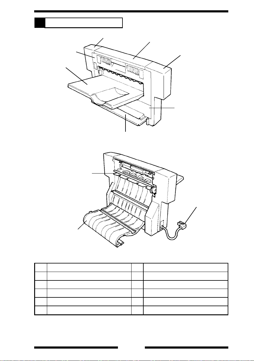
PARTS IDENTIFICATION
2
3
2
1
7
8
4
5
6
4458M001AA
10
9
4458M002AA
No. Name No. Name
1 Exit Tray 6 Exit Section Lower Cover
2 Exit Section Cover 7 Turnover Tray
3 Rear Cover 8 Exit/Turnover Sw itching Finger
4 Top Cover 9 Vertical Transport Guide
5 Front Cover 10 Hookup Cord
M-2
Page 6

CROSS-SECTIONAL VIEW
3
1
9
8
7
No. Name Function
1 Exit Rollers Feed the copy out onto the Exit Tra y.
Exit/Turnover
2
Switching Finger
Vertical Transpor t
3
Guide
Vertical Transpor t
4
Rollers
Vertical Transpor t
5
Sensor PC3
Duplex Paper
6
Take-Up Port
7 Turnover Tray
8 Turnover Rollers
Switchback
9
Sensor PC1
Directs a copy for exit or turnover depending on the
operating mode.
Serves as a guide for the copy for turnover. Used also for
clearing a misfeed.
Transports the copy for turnover. Also removes the fuser
oil from the copy.
Detects a copy to be later turned over. Serves also as a
misfeed sensor.
The port through which the copy which has been turned
over is taken up and fed into the copier for the second
copy cycle.
Prevents the portion of the copy out of the Duplex Unit for
turnover from drooping down.
Reverse the copy fed fro m the ver tical t ransport section
(switchback motion) so that it can be taken up and fed
again into the copier.
Detects the reference t iming for the switchback mot ion of
the copy fed from the vertical transport section.
2
3
4
5
6
4458M003AA
M-3
Page 7
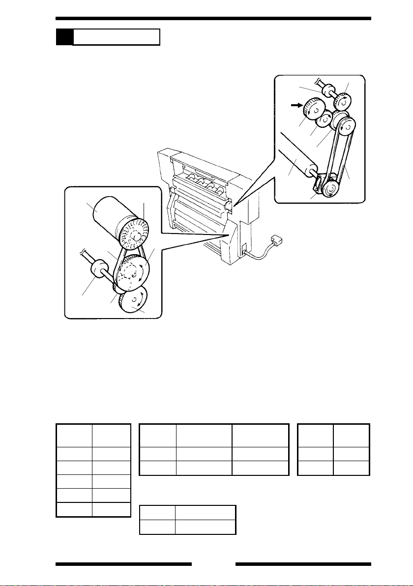
DRIVE SYSTEM
4
M1
Turnover
Roller
B2
G4
P1
PG2
G5
Exit Roller
Drive from
Copier
G1
Vertical
Transport
Roller
G3
G2
PG1
B1
CL1
4458M004AA
Gear
Symbol
G1 30
G2 24
G3 24
G4 19
G5 33
No. of
Teeth
Pulley
Symbol
PG1 31 28
PG2 15 64
No. of
Teeth, Gear
Pulley
Symbol No. of Teeth
P1 16
M-4
No. of
Teeth, Pulley
Belt
Symbol
B1 288
B2 191.01
Length
(mm)
Page 8
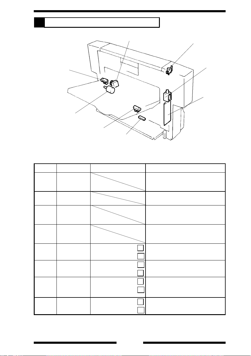
ELECTRICAL COMPONENTS LAYOUT
5
CL1
PC2
M1
PC3
PC1
◆
Functi on of Each Component
Symbol Name Input Signals (∗) Function
PWB-A Drive Board
M1
SL1
CL1
PC1
(PJ2A-8)
PC2
(PJ3A-2)
PC3
(PJ2A-9)
S1
(PJ2A-6)
Turnover
Motor
Exit/Turnover
Switching
Solenoid
Vertical
Transport
Clutch
Switchback
Sensor
Motor Pulse
Sensor
Vertical
Transport
Sensor
Duplex Unit
Set Switch
Paper present:
Paper not present:
Unblocked:
Blocked:
Paper present:
Paper not present:
Unit in position:
Unit out of position:
Performs commu nica tio n wi th the
copier and controls the elec trical
components of the Duplex Unit.
Drives the Turnove r Rollers to
effect a switchback motion.
Moves the Exit/Turnover
Switching Finger to chan ge the
paper path.
Controls the start and stop of the
Vertical Transpor t Ro llers to keep
the copy in the standby state.
L
Detects the reference tim i ng for a
switchback motion .
H
H
Detects the speed of M1.
L
L
Detects the copy present at th e
vertical transport section.
H
L
Detects whether or not the Duplex
Unit is installed in position.
H
S1
SL1
PWB-A
4458M005AA
∗
Signals at th e p r int jack on PW B-A.
M-5
Page 9
DESCRIPTION OF EACH MECHANISM AND CONTROL
6
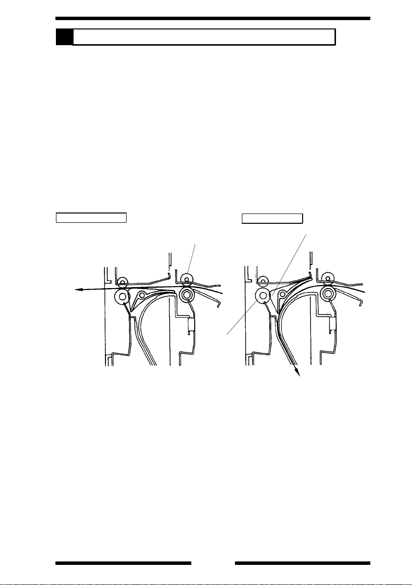
6-1. Exit/Turnover Switching Mechanism
•
The exit/turnover switching mechanism uses the Exit/Turnover Switching
Finger that is moved to change the paper path either for exit or turnover.
•
When in the E xi t mo de or when the co py i s to be fed out in the Dupl ex
mode, Exit/Turnover Switching Solenoid SL1 remains deenergized and the
copy moves above the Exit/Turnover Switching Finger and is fed out of the
copier by the Exit Rollers.
•
When the copy is to be turned over in the Duplex mode, SL1 is ener gized
and the copy moves beneath and along the Exit/Turnover Switching Finger
and is fed by t he Ve rt ical Tran sp or t Rol l er s of the Du pl e x Uni t down
towards the turnover section.
•
As noted above, S L 1 moves the Exit/Turnover Switching Finger to change
the pa per path. I t is energized when a L O W si gnal fr om t he copier is input
to PJ2A-1 on PWB-A.
SL1: Deenergized
Exit
Paper Exit
Roller of Copier
Exit Roller
SL1: Energized
Exit/Turnover
Switching Finger
To Turnover Section
4458M006AA
M-6
Page 10

6-2. Fuser Oil Cleaning Mechanism
•
Since fuser oil is on the front side of the paper after the fusing process, it is
transferred onto the surface of the PC Drum via the Transfer Film during
the seco nd co py pr o ce ss of 2- s i de d cop yin g, whi c h res ul t s i n ima ge
problems. Silicone rubber rollers are used as the Vertical Transport
Rollers of the Duplex Unit. They function to recover fuser oil from the
surface of the paper.
6-3. Paper Standby Control
•
In a Duplex mode making two or more c op y sets of an original set (which
involves two-sheet paper attraction), two sheets of paper are present in the
Duplex Unit, one waiting for take-up from the Duplex Unit following the
turnover cycle and the other remaining stationary at the vertical transport
section. (See "7. OPERATION AND CONTROL" that follows.)
•
There is no problem with the paper waiting for take-up from the Duplex Unit
as it i s d r iven independen t ly of the copier drive. The paper at th e v ertical
transport section is, however, being transported and the drive from the
copier must be cut off. To accomplish this, Vertical Transport Clutch CL1
is mounted on the sh aft of the Ve r ti c al Tr an sp ort Roller and it c ou pl e s or
cuts off the copier drive to the roller.
•
CL1 is energized to stop the Vertical Transport Roller rotation when a LOW
signal from the copier is input to PJ2A-4 on PWB-A.
M-7
Page 11

6-4. Switchback Operation (Turnover)
•
The Turnover Roller turns forward to transport the copy to the turnover
section and, as soon as the trailing edge of the copy moves past
Switchback Sensor PC1, it stops turning. The Turnover Roller then turns
backward to turn over the copy and feed it back into the copier.
•
The drive for the Turnover Roller comes from Turnover Motor M1 wh ich is
turned forward , ba ck wa rd , or st op pe d by th e si gn al s fed from the co pier as
follows.
PJ2A-2 PJ2A-3 Copy Motion
Turning forward Transported towards Turnover Tray
Turning backward
Stopped Stationary
L
H
H
H
Transported tow ar ds D uplex paper
L
take-up side
H
Copy Transported Towards Turnover
Tray
Copy
Turnover Tray
Standby Position
Horizontal Tra nspo rt
Sensor of Cop ier
Turnover Position (Copy is temporarily
stationary)
Switchback
Sensor PC1
4458M007AB
M-8
Page 12

OPERATION AND CONTR OL
7
7-1. No. of Multiple 2-Sided Copies
•
The Duple x Uni t c an st o re only up to two co pi e s in i t an d th e cop i er do es
not sto r e in memo r y the i m age data it scan ned. For these reasons, the
number of multiple 2-sided copies that can be made varies depending on
the paper size, copying mode, and whether the Duplexing Document
Feeder is used or not . Her e are t he de t ai l s .
Copy Paper Size A5, A4C (∗1) A4L, B4L, A3L
Original Placement ADF Glass ADF Glass
1-sided → 2-sided 99 sets (*2) 2 sets (*3) 2 sets (*4) 1 set
2-sided → 2-sided 2 sets (*4)
Book → 2-sided
Copyin g Mo de
*L: Lengthwise; C: Crosswise; ADF: Duplexing Document Feeder
*1: Only when two shee ts of paper ar e to b e attra cted to the Transfer D ru m. I f a
particular copy cycle does not involve attraction of two sheets of paper, the
same control is provided as that for the paper size of B5L or larger.
*2: The originals are fed by the 2-in-1 mode and a book copy cycle is repeated in
which four 2-sided copies are made.
*3: Only when Auto Color Se lect is disabled.
*4: Only when Auto Expos ure, Aut o Co lor Select , and A uto P aper/S ize are disabled.
*5: A cycle is repeated in which four 2-sided copies are made.
99 sets (*5)
2 sets (*4)
7-2. Sensor Locations
•
The illustration below locates different sensors that provide reference for
paper move ment t h roughout t he Dup le x Un i t.
PC3
PC1
Duplex Unit Side
• PC1: Switchback Sensor
• PC3: Vertical Transport
Sensor
S10
PC24
Copier Side
• PC18: Paper Leading Edg e De tecting S enso r
• PC19: Transport Rolle r Sensor
• PC21: Separating Failure D et ecting Sensor
• PC24: Horizontal Tr an spor t Sensor
• S10: Paper Exit Switch
PC18
PC21
PC19
Transfer Drum
PC Drum
4458M009AA
M-9
Page 13

7-3. 2-Sided Copying Operation
1) Making 2-Sided Copies from 2-Sided Original Using ADF (One A4C
original, one copy set)
Paper Position Operation Sequence
The copy is separated from the Transfer Drum after
the image transfer process.
Separating Failure D etect ing Sen sor PC21 is
activated.
The copy reaches Paper Exit Switch S10.
4458M101AA
Exit/Turnover Switching Solenoid SL1 is energized.
The copy is transpor ted t o the vert ical tra nspo rt
section to reach Vert ical Transport Sensor PC3.
Turnover Mo tor M1 turns forward.
4458M010AA
4458M011AA
4458M012AA
4458M013AA
The copy reaches Switchback Sensor PC1.
Turnover Motor M1 turns forward to tra nspo rt t he
copy onto the Turnover Tray.
The trailing edge of the copy moves past PC1.
M1 is temporar ily deenergized and then start s tur ning
backward. (Th e copy is turned over, and the n taken
up and fed into the copier.)
The copy reaches Horizontal Transport Sensor PC24.
As Horizontal Transport Drive Clutch CL23 is
energized, the copy is fed onto t he Synchro n izing
Rollers.
The image tran sfer to the se cond fac e of the copy is
completed a n d then the copy undergoes s ep aration
and fusing befor e being fed out of the c opie r.
4458M014AA
M-10
Page 14

2) Making 2-Sided Copies from 1-Sided Originals Using ADF (Two A4C
originals, two copy sets)
Paper Position Operation Sequence
Two sheets of pape r for the first or iginal are
separated from the Transfer Drum after the image
transfer process.
The first copy activates Separating Failure Detecting
Sensor PC21.
4458M015AA
The first copy reaches Paper Exit Switch S10.
Exit/Turnover Switching Solenoid SL1 is energized.
The first copy is tran sported t o the ver tical t ransport
section to reach Vert ical Transport Sensor PC3.
Turnover Mo tor M1 turns forward.
4458M016AA
4458M017AA
4458M018AA
4458M019AA
The first copy re aches Switchback Sensor PC 1.
Turnover Motor M1 turns forward to transport the first
copy onto the Turnover Tray.
As Vertical Transpo rt Clut ch C L1 is ene rg ized, the
second copy is stationary at the vertical transport
section.
The trailing edge of the first copy move s past PC1.
M1 is temporar ily deenergized and then start s tur ning
backward. (Th e first cop y is turned ov er, a n d then
taken up and fed into the copier.)
The first copy reaches Horizontal Transport Sensor
PC24.
As Horizontal Transport Drive Clutch CL23 is
energized, the first copy is fed onto the Synchronizing
Rollers.
The first copy reaches Paper Leading E dge D etect ing
Sensor PC18 and stops at the Synchronizing Rollers.
➀➁
M-11
Page 15

Paper Position Operation Sequence
➀
➁
As CL1 is deenergiz ed and M17 is energized, the
second copy is transpor ted t o the turn over sec tio n.
The second copy reaches PC1.
M1 turns forwa rd to transport the second copy to the
Turnover Tr ay.
4458M020AA
The trailing edge of the second cop y moves past PC1.
M1 is temporar ily deenergized and then start s tur ning
backward. (Th e second copy is turned ov er, and
then taken up and fed into the copier.) At the same
time, the first copy is again attracted to the Transfer
Drum.
4458M021AA
4458M015AA
4458M022AA
The first and secon d copies are attracted to the
Transfer Drum. When the image transfer to the
second faces of the copies is completed, the copies
undergo separation and fusing before being fed out
of the copier.
M-12
Page 16

DIS/REASSEMBLY,
ADJUSTMENT
Precautions for Disassembly, Reassembly and Adjustment
1. Before attempting to disassemble the unit, always make sure that no power is
being supplied f rom the copier .
2. While power is being supplied to the unit, do not attempt to remove/install the
print jacks from/to the PWBs or unplug/plug in the connectors.
3. If th e u ni t is run with its covers rem oved, use care not t o allo w your clot hing t o
be caught in revolving parts such as th e timing belt.
4. The ba sic rule i s do not r un the un i t any ti me du r i ng dis/reas se m bl y .
5. A toothed washer is used with the screw that secures the ground wire to
ensure positive conduction. Do not forget to insert this washer at reassembly.
6. To reasse mbl e t he un i t, re ve rse t he order of di sa ss emb l y unl e ss ot h er wi s e
specified.
7. Do not attempt to loosen or remove the screw to which red paint has been
applied.
8. The screw to which blue paint has been applied may be removed, but needs to
be adjusted whenever it has been removed.
Purpose of Applying Red Paint
Red paint is applied to those screws that cannot be readjusted or reinstalled in
the field.
Page 17

DISASSEMBLY
1
1-1. Removal of the Exterior Covers and Guides
1
6
4
4458M008AA
3
No. Cover/Gu i de Na me No. of Scr e ws Steps Requi re d Befo re Re mov al
1 Rear C ov er 4 None
2 Front Cover 4 None
3 E xi t S ec t i on Lower Cove r 4 Removal of th e Fron t and Rear Co ver s
4 Exit Section Cover 2 Removal of two ornamental covers
5 Turnover Low er Guide 2 Remov al of th e Fro nt and Rear Co vers
6 V ertica l T r a ns port G uide 2 R emoval of the F ront and Rear Co ve r s
5
4458M008AA
2
D-1
Page 18

1-2. Removal of Vertical Transport Clutch CL1
1. Remove the Front and Rear Covers.
2. Remove t he Exit Sec t i on Lower Co ver .
3. Unplug the connector of CL1.
4458D001AA
4. Loosen the screw shown to release the belt tension.
*
Do not forget to tighten this screw at reinstallation.
4458D005AA
5. Snap off one plastic ring and remove the flange and
belt.
4458D002AA
Frame
Collar
0
4458D003AA
CL1
4458D004AA
6. Loosen one screw with an Allen wrench to remove
CL1 and the collar.
*
When reinstalling CL1, press it against the collar
and, a t the same tim e, t ig hten the screw.
Hook the l oc k of the c lutch onto the frame.
D-2
Page 19

1-3. Removal of the Vertical Transport Roller (Metallic One)
1. Remove the Front and Rear Covers.
2. Unhook two te ns io n c oi l spri n gs .
4458D006AA
3. Remove the plastic ri ngs and bushings from the front
and rear ends and then remove the Vertical Transport
Roller.
4458D007AA
1-4. Removal of the Vertical Transport Roller (Rubber One)
1. Remove the Front and Rear Covers.
2. Remove t he Exit Sec t i on Lower Co ver .
3. Remove V er t i cal Tr a nsp or t C l ut c h CL 1 an d c ol la r .
4. Remove the plastic ring and bearing from the rear end.
4458D008AA
4458D009AA
5. Remove the plastic ri ngs and bushings from the front
end.
6. Remove t he Vert ic al Transport Rolle r.
D-3
Page 20

1-5. Removal of the Turnover Entrance Guide
1. Remove t he Front and Re ar Co ver s.
2. Remove the Turnover Lower Guide.
3. Remove f our scre ws at the fro nt and rear and the
Turno ver Entrance Gui de.
4458D014AA
*
Try to pre ss the T urn o ver Entr an c e G u ide up as
shown at reins t al l a tio n.
0
ADJUSTMENTS
2
Vertical
Transport
Frame
Turnover Entrance
Guide
4458D015AA
2-1. Adjustment of Dup. Left-Margin
Requir e m en ts : The di s t an ce be tween the fr o nt e dg e of th e p ap er and the f ront edg e of t he t est
pattern should be 3 ±1.5mm.
1. Set the copier into the Service mode and select the
following functions in that order:
"Machine Adjust," "PRT Area," and "Dup. Left-Margin."
4458D016AA
2. Select the drawer to be adj usted and press the Start
key.
3. M ea sur e d i me ns io n " A" o n th e te s t p rint fed out of the
copier.
*: No adjustments are necessary if the measurement
A
4458D017AA
is 3 ±1.5mm.
4. If the measurement taken in step 3 falls outside the
speci f i ed ra ng e, a dj u s t usin g th e ▲ or ▼ key.
D-4
Page 21

2-2. Adjustment of Exit/Turnover Switching Solenoid SL1
1. R em ov e t he Front Cover .
2. R em ov e t he ha r ness of Du p le x Uni t Set S wi t c h S1
from t he edge cov er.
SL1
3. Unplug the connector from Drive Board PWB-A.
SL1
PWB-A
4458D010AA
4458D011AA
4458D012AA
Upper Guide Plate
Exit/
Turnover
Switching
Finger
4. Remove one screw and the solenoid assy.
5. Unhook the tension coil spring.
6. R em ov e t wo s cr e ws an d th e sol e no i d.
*
When securing the solenoid at reinstallation, slide it
downward as far as it will go.
*
When sec u ri ng t he s o l en oi d assy, en sur e that the
Exit/Turnover Switching Finger is in contact with the
sponge of th e Upper Gui de Plate with the solenoid i n
the energized position.
After reinsta llati on, check that the switching finger
operates smoothly.
4458D013AA
D-5
Page 22

TROUBLESHOOTING
Genera l Precautions
1. When servicing the unit with its covers removed, use utmost care to prevent
your hands, c l othing, and tools fro m being caught in revol ving parts.
2. Befor e att e m pti n g to rep l ac e parts and un pl u gg i ng co nn ectors, mak e sure that
no power is being supplied from the copier.
3. Never cre at e a clos ed cir cuit acr oss conne ctor pi ns exce pt those a ut horized in
the text and on the PWB.
4. When creating a closed circuit and measuring a voltage across connector pins
speci fi e d in the text, be su re to us e th e gre en wi re (GND).
5. Keep all disassembled parts in good order and keep tools under control so that
none will be lost or damaged.
Reading the Text
1. If a component on a PWB or any other functional part including a motor is
defective, the text only instructs you to replace the whole PWB or functional
part and does not give troubleshooting procedure applicable within the
defective part.
2. The text assumes that there are no breaks in the harnesses and cords and all
connectors are plugged into the right positions.
Page 23

MISFEED DETECTION
1
1-1. Misfeed Detection Conditions
A misfeed in the Duplex Unit is detected under any of the following conditions and a misfeed
•
indication is given on the control panel of the copier. A misfeed can be reset by unlocking and
locking the Duplex Unit.
A mis fe ed a t th e ve r t i cal transp o r t s ection
•
Type Detection Timing
Paper left Vertical Transport Sensor PC3 is unblocked ( L ) when the Power
Leading edge of paper PC3 is not unblocke d ( L ) even after t he la ps e of appr ox. 3.3 se c . af te r
Trailing edge o f paper PC3 is not blocke d ( H ) even after t he lapse of appro x. 3.3 sec . after
A misfeed at the turnover section
•
Type Detection Timing
Paper left Switchback Sensor PC1 is activated ( L ) when the Power Switch is
Leading edge of pape r PC1 is not a c tiv a te d ( H ) even after t he l a pse of appr o x. 1.2 sec . af te r
Trailing edge o f paper PC1 is ac ti va ted ( L ) even afte r the l a ps e of appro x. 4.8 se c . af te r PC 1
Paper which has been
turned over
Switch i s tu rned ON, a m i sf eed is res et , or the F ron t Door is ope ne d an d
closed.
Paper Ex i t S wi t ch S 10 of the c opier h a s detected the leading edge of the
paper.
S10 of the copier has detected the trailing edg e of the pa per.
turned ON, a misfeed is reset, or the Front Door is opened and closed.
PC3 has d et ec t ed t he l e ad i ng edge of the paper.
has det ec t ed t he l e ad i ng edge of the pa p er.
PC1 dete cts no paper at a timing when it should have detected paper
after it has been turned over (e.g., when the paper which has been turned
over i s pulled out).
A mis fe ed a t the Dup l e x pap er tak e-u p section
•
Type Detection Timing
Paper lef t Horiz on ta l Tra ns p ort S e ns o r PC2 4 of th e c op i e r i s blo cke d ( L ) when
Leading edge of pape r PC24 of th e c opie r is no t bl ocked ( L ) even af ter the la p se o f ap prox.
Trailing edge o f paper PC24 is no t unblo c k ed ( H ) e v en af ter t he lapse of a pprox. 1.8 se c.
the Power Switch is turned ON, a misfeed is reset, or the Front Door is
opened a n d cl o se d.
1.8 sec. a ft er PC1 ha s d et ec t ed t he l e ad i ng edge of the pap e r whi ch was
turned over.
after PC1 has detected the trailing edg e of the pape r which was turned
over.
T-1
Page 24

1-2. Mi sf e ed Trouble s h oo t ing Procedures
A Misfeed at the Vertical Transport Section
•
Symptom
A misfeed
occurs
immediately
after the
Power Switch
has been
turned ON.
A misfeed
occurs before
paper
reaches the
vertical
transport
section.
A misfeed
occurs before
paper
reache s PC3.
Step
No.
1 Is Vertic al T r ansport Sens or
PC3 unblocked by a sheet of
paper present at the vertical
trans po rt sec t ion of the Dup l ex
Unit?
2 Doe s the a ctuator of PC 3
operate properly?
3 Is the voltage across PJ2A-9 on
PWB-A an d G ND DC 5 V? D oe s
that voltage change to DC0V
when PC3 is unblocked?
1 Is Exit/Turnover Switching
Solenoid SL1 energized during
the Duplex mode?
2 Does the voltage across PJ2A-1
on PWB-A and GND change
from DC5V to DC0V when SL1
is ener gized?
3 Has the Exit /Turnover Swit ching
Finge r been adjusted properly?
1 Do th e Ve rti c a l T r an s po rt
Rollers turn when drive is
trans mitted fro m t he c o pi e r?
2 Is the voltage across PJ2A-4 on
PWB-A and GND DC5V
normally?
3 Are th e V ert i c al Tr an s po rt
Rollers dirty or scratched?
Check It e m Re sult Action
YES Remove the paper from the
vertical transport section.
NO C h eck th e ins t al le d positio n of
PC3 and check the actuator for
deform at i on a n d foreig n matter.
YES Make checks on the copier side.
NO C h eck the w ir i n g be tw ee n
PWB-A an d PC 3 an d, i f i t i s
intact, replace PC3 or PWB-A.
YES G o to st ep 3.
YES Ch ec k th e wi ri n g be tw ee n
PWB-A an d SL 1 an d, i f i t i s
intact, replace SL1 or PWB-A.
NO Make checks on the copier side.
YES Clean the Exit/Turnover
Switc hi n g Fi ng er and gu i de
plate.
NO Adjust SL1.
YES G o to st ep 3.
YES Ch ec k th e wi ri n g be tw ee n
PWB-A and Vertic al Tr an s port
Clutch CL1 and, if it is intact,
replace CL1 or PWB-A.
NO Make checks on the copier side.
YES Cl e an o r re p l ace the de fect i ve
Vertical Transport Roller.
NO Clean the Vertical Transport
Guide an d c he ck it fo r
deformation.
T-2
Page 25

A Misfeed at the Vertical Transport Section
•
Symptom
A misfeed
occurs after
paper has
reached
Vertical
Transport
Sensor PC3.
Step
No.
1 Does Turnover Motor M1 turn
when pa pe r is fe d int o th e
Duplex Unit?
2 Does the voltage across PJ2A-2
on PWB-A and GND change
from DC5V to DC0V when M1 is
energized?
3 Doe s the a ctuator of PC 3
operate properly?
4 Is the voltage across PJ2A-9 on
PWB-A an d G ND DC 5 V? D oe s
that voltage change to DC0V
when PC3 is unblocked?
Check It e m Re sult Action
YES G o to st ep 3.
YES Ch ec k th e wi ri n g be tw ee n
PWB-A and M1 and, if it is
intact, replace M1 or PWB-A.
NO Make checks on the copier side.
NO C h eck th e ins t al le d positio n of
PC3 and check the actuator for
deform at i on a n d foreig n matter.
YES Make checks on the copier side.
NO C h eck the w ir i n g be tw ee n
PWB-A an d PC 3 an d, i f i t i s
intact, replace PC3 or PWB-A.
T-3
Page 26

A Misfeed at the Turnover Section
•
Symptom
A misfeed
occurs
immediately
after the
Power Switch
has been
turned ON.
Paper is yet
to reac h P C 1.
Paper is
stationary at
the Tur no ver
Rollers.
Paper is not
transported to
the Dupl e x
paper take-up
side.
Step
No.
1 Is Switchback Sensor PC1
activ a te d by a sheet of pape r
present at the turnover section
of the Duplex Unit (or dust on
the underside of the sensor)?
2 Is P C1 i n sta l l ed correct ly ? NO C o rr ect th e i n st a lled pos i ti on of
3 Is the voltage across PJ2A-8 on
PWB-A an d G ND DC 5 V? D oe s
that voltage change to DC0V
when a sheet of paper is
inserted to activate PC1?
1 Is the Turnover Entrance Guide
deformed or dirty?
1 Does Turnover Motor M1 turn
when pa pe r is fe d int o th e
Duplex Unit?
2 Does the voltage across PJ2A-2
on PWB-A and GND change
from DC5V to DC0V when M1 is
energized?
1 Doe s M1 tu r n ba ck wa r d af te r
paper has been fed out onto the
Turnover Tray?
2 Does the voltage across PJ2A-3
on PWB-A and GND change
from DC5V to DC0V when M1 is
energized?
Check It e m Re sult Action
YES Remove the paper from the
turnover section. Or clean the
unders i de o f th e senso r .
PC1.
YES Make checks on the copier side.
NO C h eck the w ir i n g be tw ee n
PWB-A an d PC 1 an d, i f i t i s
intact, replace PC1 or PWB-A.
YES Clean or replace the Turnover
Entran c e Gui d e.
NO C heck the Vertic al T r ansport
Guide an d V ert i c al Tran s po rt
Rollers for dirt and deformation.
YES Clean the Turnover Rollers and
Turno ver Guide.
YES Ch ec k th e wi ri n g be tw ee n
PWB-A and M1 and, if it is
intact, replace M1 or PWB-A.
NO Make checks on the copier side.
YES Clean the Turnover Rollers and
Turno ver Guide.
YES Ch ec k th e wi ri n g be tw ee n
PWB-A and M1 and, if it is
intact, replace M1 or PWB-A.
NO Make checks on the copier side.
T-4
Page 27

A Mis fe ed a t the Dup l e x Pa p e r T ake-U p S e c ti on
•
Symptom
A misfeed
occurs
immediately
after the
Power Switch
has been
turned ON.
A misfeed
occurs before
paper
reaches
Horizontal
Transport
Sensor PC24.
A misfeed
occurs after
paper has
reached
PC24 of th e
copier.
Step
No.
1 See TROUBLESHOOTING of
the copier.
1 Is the Turnover Entrance Guide
or Turnover Lower Guide
deformed or dirty?
2 Is the Turnover Roller or the
Duplex Paper Take-Up Guide of
the copier deformed or dirty?
1 See TROUBLESHOOTING of
the copier.
Check It e m Re sult Action
YES Clean or replace the Turnover
Entran c e Gui d e or Turn ov e r
Lower Guide.
YES Clean or replace the Turnover
Roller or the Dupl ex Pa per
Take-U p G ui d e of th e c op i e r.
NO Check Horizontal Transport
Drive C l ut c h CL 23 o f th e c opi e r.
T-5
Page 28

Use of this manual should
be strictly supervised to
avoid disclosure of
confidential information.
 Loading...