

Page 1

FrameMaker Ver.5.5(PC) DF-331 OPTION FOR 7915/7920
01.02.09
DF-331
SERVICE MANUAL
11563
Page 2

FrameMaker Ver.5.5(PC) DF-331 OPTION FOR 7915/7920
01.02.09
CONTENTS
GENERAL,
MECHANICAL/ELECTRICAL
1. SPECIFICATIONS ........................................................................................... M-1
2. COMPONENT IDENTIFICATION .................................. ........................... .......M-3
3. CROSS-SECTIONAL VIEW ............................................................................M-4
4. DRIVE SYSTEM ..............................................................................................M-5
5. ELECTRICAL COMPONENT LAYOUT ...........................................................M-6
6. DESCRIPTION OF MODES ............................................ .............. ..................M-7
6-1. Mixed Original Mode . ...............................................................................M-7
6-2. 1-Sided Mode ..........................................................................................M-7
6-3. 2-Sided Mode ..........................................................................................M-7
6-4. Single Feed Mode ....................................................................................M-7
7. DOCUMENT TAKE-UP/FEEDING MECHANISM ............................................M-8
7-1. Parts Identification ...................................................................................M-8
7-2. Document Pick-Up Mechanism ...............................................................M-9
7-3. Document Take-Up Mechanism ..............................................................M-11
8. DOCUMENT TRANSPORT MECHANISM ......................................................M-13
8-1. Parts Identification ................................................................................... M-13
8-2. Document Transport Mechanism .............................................................M-13
9. TURNOVER/EXIT MECHANISM .....................................................................M-15
9-1. Parts Identification ................................................................................... M-15
9-2. Document Transport Mechanism .............................................................M-15
9-3. Turnover/Exit Switching Mechanism ........................................................M-17
10. SCALE DRIVE MECHANISM ..................... .....................................................M-18
10-1.Parts Identification ....................... ............. .... .... ............. .... ............. .... .... .M-18
10-2.Pressing of the Scale Drive Mechanism ..................................................M-18
10-3.Scale Drive Mechanism ...........................................................................M-19
10-4.Thin Paper Mode ....................................................... .... ...... ........... ...... ...M-19
11. MISCELLANEOUS ..........................................................................................M-20
11-1.Document Size Detection Mechanism .....................................................M-20
(1) Document Width Detection ..............................................................M-20
(2) Document Length Detection ............................................................ M-20
(3) Document Size Detection ................................................................M-21
11-2.15° Open Detection Mechanism ..............................................................M-22
11-3.Raised/Lowered Position Detection Mechanism .....................................M-22
TEST MODES
1. OUTLINE OF THE TEST MODES ...................................................................S-1
1-1. Test Mode Setting Procedure ..................................................................S-1
1-2. Types of Test Modes ...............................................................................S-1
2. PAPER PASSAGE CHECK ............................................................................. S-2
2-1. Paper Passage Modes ............................................................................S-2
2-2. Paper Passage Check Procedure ...........................................................S-2
2-3. Indication by LEDs in Paper Passage Check ..................................... .... .S-3
(1) Indication by LEDs in closure failure .......................................... .....S-3
i
Page 3

FrameMaker Ver.5.5(PC) DF-331 OPTION FOR 7915/7920
01.02.09
(2) Indication by LEDs in Misfeed, Trouble and Warning ......................S-3
3. UNIT CHECK ..................................... ............................ ........................... .......S-4
3-1. Unit Check Modes ...................................................................................S-4
3-2. Unit Check Procedure ..............................................................................S-4
(1) Pick-Up Motor check ...................... .................................................S-4
(2) Take-Up Motor check ....................... ........................... ....................S-5
(3) Main Motor check .............. ............................ ........................... .......S-5
(4) Turnover/Exit Motor che ck ................................... ............... .............S-5
(5) Scale Drive Motor check .................................................................. S-6
(6) Turnover Solenoid check .................................................................S-6
4. SENSOR CHECK ................................ ............................ ........................... .....S-7
4-1. Sensor Check Mode ............................................................................... .S-7
4-2. Sensor Check Proc edure ....................................... ........................... .......S-8
(1) Sensor Check 1 check .............. ........................... ............................S-8
(2) Sensor Check 2 check .............. ........................... ............................S-8
5. BOARD CHECK ..............................................................................................S-9
5-1. Board Check Mode .................................................................................. S-9
5-2. Board Check Procedure .......................................................................... S-9
DIS/REASSEMBLY, ADJUSTMENT
1. MAINTENANCE SCHEDULE ..........................................................................D-1
2. DISASSEMBLY ...............................................................................................D-2
2-1. Removal of the Transport Belt .................................................................D-2
2-2. Removal of the Pick-Up Rolls, Take-Up Rolls, and Separator Pads .......D-3
3. ADJUSTMENTS ..............................................................................................D-5
3-1. Adjustment of Ske w in the ADF ............................................. ..................D-5
3-2. Adjustment of the Document Feed Tray Reference Position ...................D-6
3-3. Adjustment of the Single Feed Tray Reference Position .........................D-7
3-4. Adjustment of the Document Stop Position in the 1-Sided and
1-Sided Mixed Original Mode ..................................................................D-8
3-5. Adjustment of the Document Stop Position in the 2-Sided Mode ............D-9
3-6. Adjustment of the Document Stop Position in the Single Feed Mode .....D-10
3-7. Adjustment of Turnover Solenoid ............................................................D-11
TROUBLESHOOTING
1. MISFEED DETECTION ................................ ............... ........................... .........T-1
2. MISFEED TROUBLESHOOTING PROCEDURES .........................................T-3
3. Closure Failure Detection ................................................................................T-7
4. Time chart .................................... ............... ........................... ..........................T-8
4-1. 1-Side Original Mode ...............................................................................T-8
4-2. Mixed Original Mode ................................................................................T-9
4-3. 2-Side Original Scanning Mode ...............................................................T-10
4-4. Single Feed Mode ....................................................................................T-11
ii
Page 4

FrameMaker Ver.5.5(PC) DF-331 OPTION FOR 7915/7920
01.02.09
GENERAL,
MECHANICAL/ELECTRICAL
Page 5

FrameMaker Ver.5.5(PC) DF-331 OPTION FOR 7915/7920
01.02.09
1. SPECIFICATIONS
Name : Duplexing Document Feeder
Type : Paper Take-Up : Take-up from top of stack, U-turn feeding
Installation : Mounted on the copier
Type of Document : Plain paper : 1-Sided mode - 50 g/m² to 110 g/m²
Detectable Document
Sizes
Capacity : Document Feed Tray: 50 sheets -- 80 g/m²
Alignment : Rear Document Edge Guide
Document Loading : Face up
Modes : Mixed Original
Power Source : DC 24 V -- supplied from the copier
Power Consumption : 60 W or less
Dimensions : Width 603 mm
Weight : 12.0 kg
Operating Environment : Same as copier
Transport : Single-belt transport
Turnover : Loop turnover
Ejection : Straight ejection
2-Sided mode - 60 g/m² to 90 g/m²
Single Feed mode - 35 g/m² to 200 g/m²
: Metric Area (Standard)
A5 C/L, B5 C/L, A4 C/L, B4 L, A3 L, 11 × 15 L,
8-1/2 × 11 L, 8 × 13 L
Inch Area (Standard)
A4 L, 5-1/2 × 8-1/2 C/L, 8-1/2 × 11 C/L, 8-1/2 × 14 L,
11 × 15 L, 11 × 17 L
Document Exit Tray: 50 sheets -- 80 g/m²
1-Sided
2-Sided
Single Feed
Height 110 mm
Depth 502 mm -- excluding Document Exit Tray
M-1
Page 6
FrameMaker Ver.5.5(PC) DF-331 OPTION FOR 7915/7920
01.02.09
Originals Which Should
Not be Used
Type of Original Possible Trouble
Sheets stapled or clipped together Take-up failure, damaged sheet, defective
Sheets glued together Take-up failure, damaged sheet
Sheets folded, torn, or wrinkled Take-up failure, damaged sheet
Sheets severely curled Sheets mis-fed due to being dog-eared or
Sheets weighing less than 40 g/m² Damaged sheet
Originals for Which Feeding is not Guaranteed
Type of Original Possible Trouble
Pieces of paper pasted up on a sheet Folded or torn pasted-up pieces
Slightly curled sheets: curl 10 to 15 mm Dog-eared pages, ejection failure
Heat-sensitive paper Folded leading edge, ejection failure, trans-
Coated sheets Take-up failure, transport failure
Translucent paper Take-up failure, transport failure
Sheets just fed out of the copier Take-up failure, transport failure
Perforated sheets: loose-leaf, etc. Multiple feed due to burrs in perforations
Sheets with two to four holes Transport failure
Sheets folded in half or Z-folded Transport failure, distorted image
Sheets weighing 40 g/m² to 50 g/m² Folded leading edge
Sheets with surface irregularities:
letterhead, etc.
Pencil-written sheets Dirty originals
Folded sheets Distorted image, multiple feed, take-up
Sheets of a size outside the range detectable by the ADF
: The following types of originals, if used with the ADF, are
very likely to cause trouble.
drive mechanism due to jammed staples or
clips.
fed in askew
: The following types of originals, if used with the ADF, may
or may not cause trouble.
port failure
Take-up failure
failure
Void image
M-2
Page 7

FrameMaker Ver.5.5(PC) DF-331 OPTION FOR 7915/7920
01.02.09
2. COMPONENT IDENTIFICATION
1
8
9
10
2
3
4
7
11
5
4490M001AA
6
1. Hookup Cord
2. Rear Cover
3. Document Feed Tray
4. Upper Cover
5. Single Feed Tray
6. Take-Up Cover
7. Document Edge Guide
13
12
4652M501AA
8. Exit Cover
9. Document Exit Tray
10. Transport Belt
11. Magnet
12. Holder Touch Lever
13. Scale Drive Lever
M-3
Page 8

FrameMaker Ver.5.5(PC) DF-331 OPTION FOR 7915/7920
01.02.09
3. CROSS-SECTIONAL VIEW
22
21
20
17
19
18
1. Pick-Up Roll
2. Empty Sensor PC1
3. Take-Up Roll
4. Separator Pad
5. Registration Sensor PC2
6. Registration Driven Roller
7. Registration Drive Roller
8. Single Feed Empty Sensor PC9
9. Single Feed Roller
10. Single Feed Roll
11. Width Sensor 1/2/3 PC5/6/7
12. Transport Belt Drive Roller
13. Transport Belt
16
15
2423
25
14
14. Transport Rolls
15. Transport Belt Driven Roller
16. Transport Roll
17. Turnover Roller
18. Exit Sensor PC3
19. Exit Roller
20. Exit Roll
21. Turnover/Exit Switching Plate
22. Turnover Roll
23. Turnover Sensor PC4
24. Turnover Roll
25. Transport Roller
123456
13
7
8
9
10
11
12
4652M502AA
M-4
Page 9
FrameMaker Ver.5.5(PC) DF-331 OPTION FOR 7915/7920
01.02.09
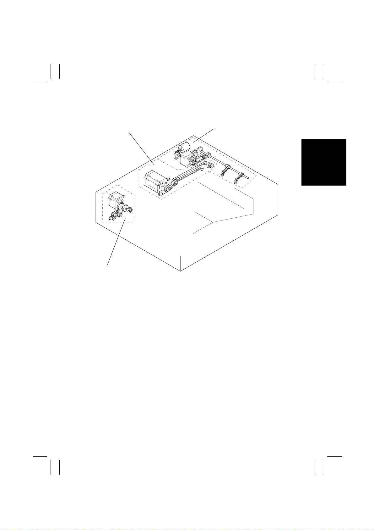
4. DRIVE SYSTEM
Document Transport
Turnover/Exit/Scale Drive
Document Take-Up/Feeding
4652M503AA
M-5
Page 10

FrameMaker Ver.5.5(PC) DF-331 OPTION FOR 7915/7920
01.02.09
5. ELECTRICAL COMPONENT LAYOUT
M2
SL1
PC11
M4
PC3
PWB-A
M5
PC8
M1
M3
PC4
PC12
PC1
PC9
PC2
PC10
PC5
PC6
PC7
4652M504AA
Code Name Code Name
PWB-A
M1
M2
M3
M4
M5
SL1
PC1
PC2
PC3
PC4
Main Control Board
Pick-Up Motor
Take-Up Motor
Main Motor
Turnover/Exit Motor
Scale Drive Motor
Turnover Solenoid
Empty Sensor
Registration Sensor
Exit Sensor
Turnover Sensor
PC5
PC6
PC7
PC8
PC9
PC10
PC11
PC12
Paper Width Sensor 1 (Option)
Paper Width Sensor 2
Paper Width Sensor 3 (Option)
Pick-Up Sensor
Single Feed Empty Sensor
Take-Up Cover Open/Close
Sensor
Exit Cover Open/Close Sensor
Scale Drive Sensor
M-6
Page 11

FrameMaker Ver.5.5(PC) DF-331 OPTION FOR 7915/7920
01.02.09
6. DESCRIPTION OF MODES
6-1. Mixed Original Mode
• The copier detects the size of each page of the document as it is taken up and fed in and,
according to the size detected, feeds the copy paper of the corresponding size selected
from among the available paper sources.
• The mode is mainly used when making copies from a document set consisting of pages
of different sizes.
6-2. 1-Sided Mode
• When a multi-page document is being copied, the copier detects the size of only the first
page of the document and copies the subsequent pages based on that size detection.
• This saves the copier the time required for detecting the sizes of the subsequent pages
of the document, making for a faster and more efficient paper feed timing.
NOTE
If a document of pages of varying sizes is used in this mode, image trouble could result
including missing copy image. (The system does not, however, force a misfeed condition.)
6-3. 2-Sided Mode
• The ADF automatically turns over 2-sided originals for a speedy copying operation (copies are made in the order of the first and second pages).
6-4. Single Feed Mode
• This mode may be used when the user wants to make copies from an original for which
feeding is not guaranteed (pasted-up sheet, translucent paper, heat-sensitive paper,
etc.).
• When a single original is inserted into the Single Feed Tray, the ADF automatically takes
it up and feeds it in to let the copier run a single copy cycle.
• Each original is transported at a low speed.
M-7
Page 12

FrameMaker Ver.5.5(PC) DF-331 OPTION FOR 7915/7920
01.02.09
7. DOCUMENT TAKE-UP/FEEDING MECHANISM
7-1. Parts Identification
1
16
15
14
13
12
1. Take-Up Motor M2
2. Empty Sensor PC1
3. Single Feed Roller
4. Single Feed Empty Sensor PC9
5. Registration Roller
6. Registration Sensor PC2
7. Paper Width Sensor 1 PC5: Option
8. Paper Width Sensor 2 PC6
9. Paper Width Sensor 3 PC7: Option
2
3
4
5
11
10
10. Take-Up Cover Open/Close Sensor
PC10
11. Take-Up Rolls
12. Separator Pads
13. Pick-Up Rolls
14. Document Stoppers
15. Pick-Up Sensor PC8
16. Pick-Up Motor M1
6
7
8
9
4652M505AB
M-8
Page 13
FrameMaker Ver.5.5(PC) DF-331 OPTION FOR 7915/7920
01.02.09
7-2. Document Pick-Up Mechanism
• The document pick-up mechanism consists of the Document Stoppers and Pick-Up
Rolls.
• The Document Stoppers determine the leading edge position of the document loaded in
the ADF.
• They are in the lowered position when in their standby position and raised when a document take-up sequence is started.
• The Pick-Up Rolls are in the raised position in their standby state and lowered when a
document take-up sequence is started, pressing the document set downward during the
sequence with the tension of the Document Pressure Springs.
• The operation of the Document Stoppers and Pick-Up Rolls is controlled by Pick-Up
Motor, Pick-Up Sensor, and a cam.
Pick-Up Rolls
Document Pressure Springs
Pick-Up Sensor PC8
Document Stoppers
Pick-Up Motor M1
4490M007AB
M-9
Page 14
FrameMaker Ver.5.5(PC) DF-331 OPTION FOR 7915/7920
01.02.09
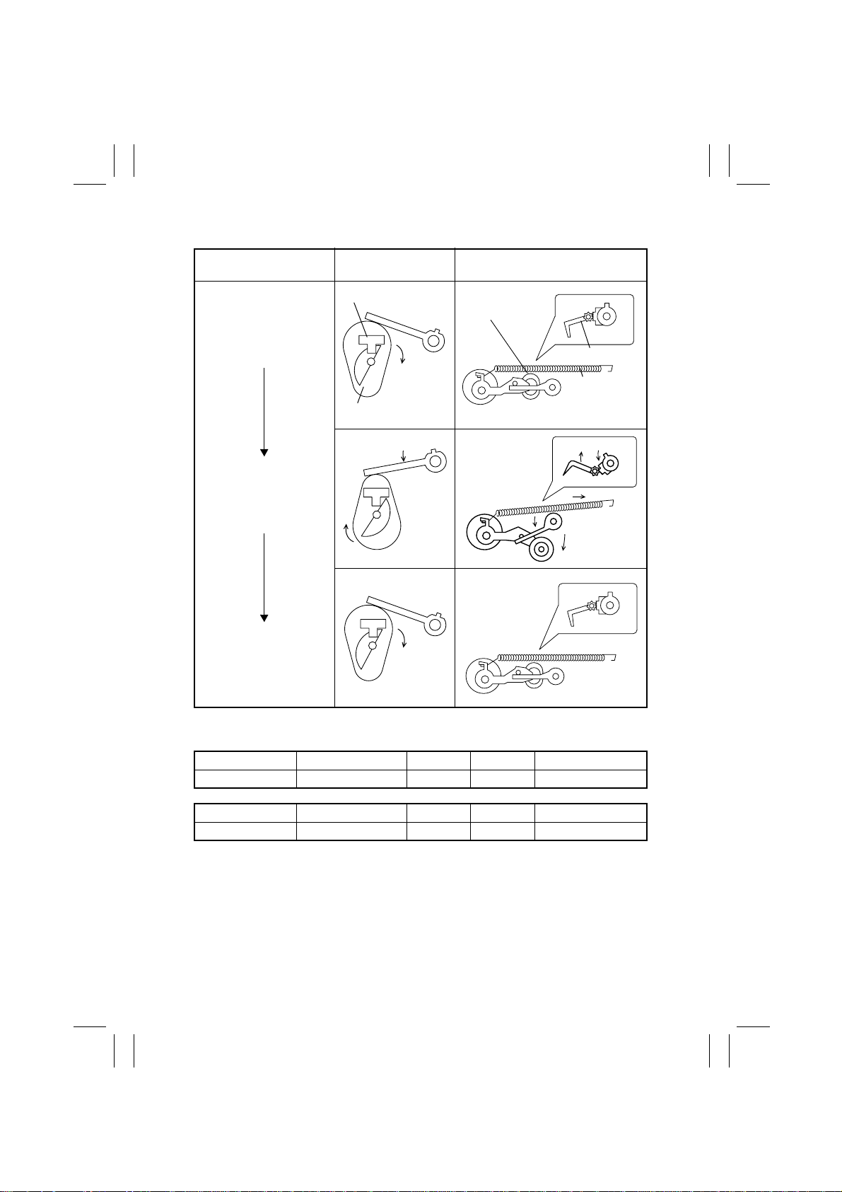
✽
Control of Operation of the Document Stoppers and Pick-Up Rolls
Home position
Pick-Up Rolls press document; Document Stoppers
retract.
Home position
PC8 and Cam
Operation
Pick-Up Sensor PC8
Cam
4490M008AA
4652M506AA 4652M517AA
Document Stoppers/Pick-Up
Rolls Operation
Pick-Up Roll
Document Stopper
Document
Pressure Spring
4490M009AA
4490M008AA
✽
Pick-Up Motor Control
CONTROL SIGNAL ON OFF WIRING DIAGRAM
M1 PWB-A PJ8A-2 L H 7 - H
CONTROL SIGNAL Blocked Unblocked WIRING DIAGRAM
PC8 PWB-A PJ12A-2 L H 3 - I
M-10
4490M009AA
Page 15

FrameMaker Ver.5.5(PC) DF-331 OPTION FOR 7915/7920
01.02.09
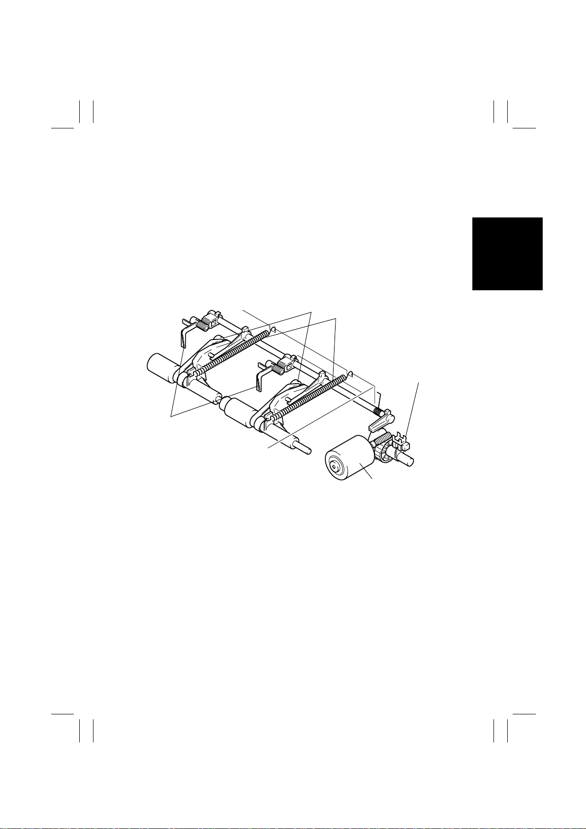
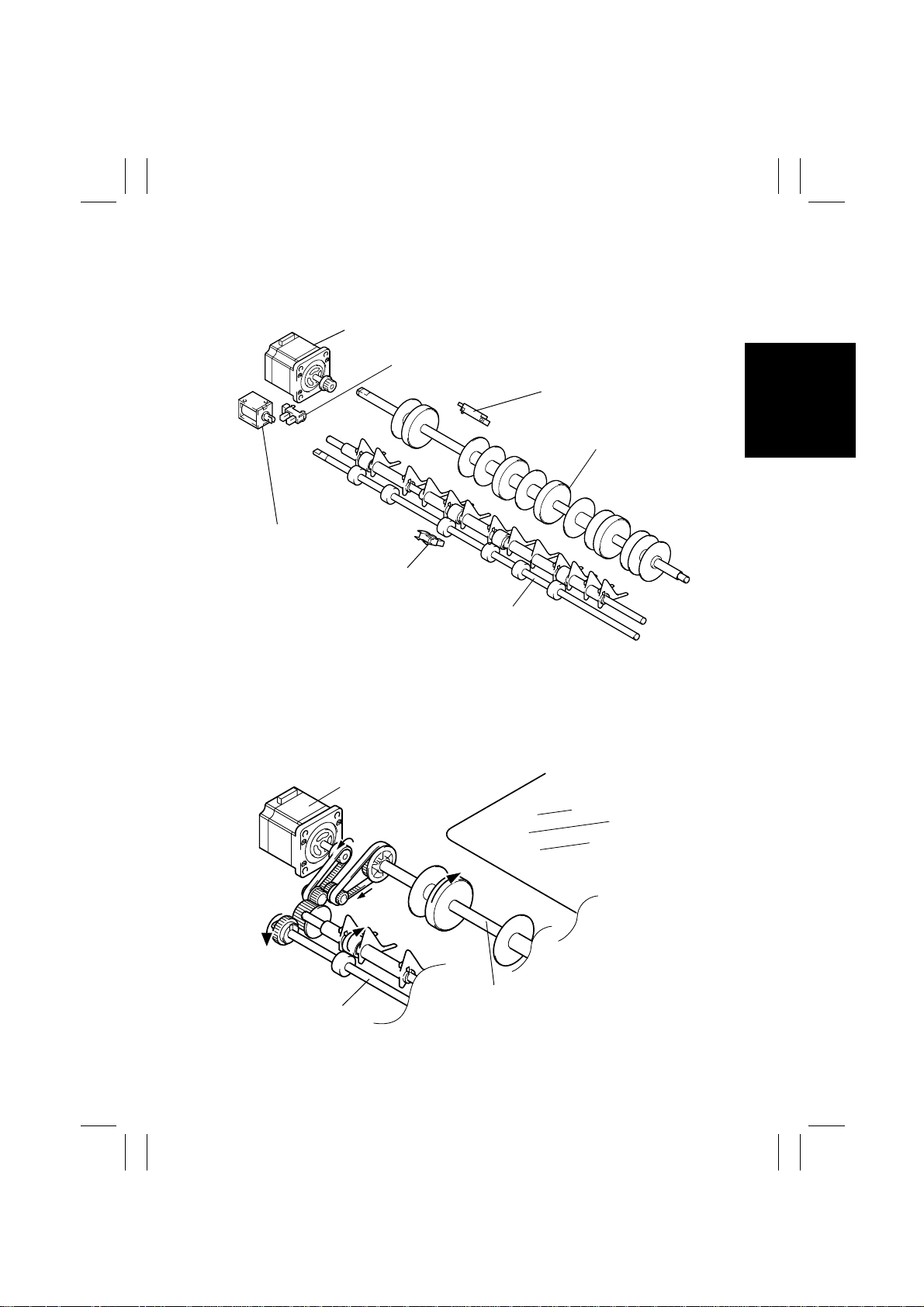
7-3. Document Take-Up Mechanism
• The Pick-Up Rolls and Take-Up Rolls turn to transport the document loaded in the Document Feed Tray up to the Registration Roller.
• The Single Feed Roller, on the other hand, turns to transport the document placed in the
Single Feed Tray.
• The Pick-Up Rolls, Take-Up Rolls, and Single Feed Roller are driven by Take-Up Motor.
• To drive the Single Feed Roller, Take-Up Motor is turned backward, at which time the
Take-Up Roll Shaft also turns backward. Because of the functioning of the one-way pulley, however, the backward rotation of the shaft is not transmitted to the Pick-Up Rolls or
Take-Up Rolls.
• The Front Separator Pads and Separator Pads together function to prevent double feed
when two or more pages of a document set are taken up.
One-Way Pulley
Take-Up Motor M2
Take-Up Roll Shaft
Pick-Up Rolls
Front Separator Pads
Separator Pads
Take-Up Rolls
Single Feed
Roller
Registration Roller
4490M012AD
M-11
Page 16

FrameMaker Ver.5.5(PC) DF-331 OPTION FOR 7915/7920
01.02.09
✽
Take-Up Motor Control
• The pulse signals output from PJ7A on PWB-A are supplied to the two coils inside TakeUp Motor and the combination and sequence of the pulse signals energized are varied to
turn Take-Up Motor forward or backward.
• The distance over which an original is transported is detected by counting the number of
pulses generated.
PWB-A
PJ7A-5 L H H L
PJ7A-4 L L H H
PJ7A-6 H L L H
PJ7A-3 H H L L
Forward
Rotation
Backward
Rotation
Sequence
1234
M2 PWB-A PJ7A-3~6 Pul se Output 7 - I
Pick-Up Rolls and Take-Up Rolls are turned to take up an
original.
The Single Feed Roller is turned to take up an original.
CONTROL SIGNAL ON OFF WIRING DIAGRAM
M-12
Page 17

FrameMaker Ver.5.5(PC) DF-331 OPTION FOR 7915/7920
01.02.09
8. DOCUMENT TRANSPORT MECHANISM
8-1. Parts Identification
1
4
2
3
4650M507AA
1. Main Drive Motor M3
2. Registration Driven Roller
3. Registration Drive Roller
4. Transport Belt
8-2. Document Transport Mechanism
• Rotation of the Registration Rollers and Transport Belt results in the original fed from the
Document Feed Tray or Single Feed Tray being transported up to the Original Width
Scale.
• The Registration Rollers and Transport Belt are driven by Main Drive Motor.
Main Drive Motor M3
Registration Rollers
Transport Belt
4490M014AA
M-13
Page 18

FrameMaker Ver.5.5(PC) DF-331 OPTION FOR 7915/7920
01.02.09
✽
Main Drive Motor Control
• The pulse signals output from PJ6A on PWB-A are supplied to the two coils inside Main
Drive Motor and the combination and sequence of the pulse signals energized are varied
to turn Main Drive Motor forward or backward.
• The distance over which an original is transported is detected by counting the number of
pulses generated.
• The motor speed is controlled by varying the cycle “A” of the pulse signal.
PWB-A
PJ6A-3 L H H L
PJ6A-5 L L H H
PJ6A-4 H L L H
PJ6A-6 H H L L
Forward
Rotation
Backward
Rotation
Sequence
1234
M3 PWB-A PJ6A-3~6 Pulse O utput 8 - G
A
Transports the original toward the Original Width Scale.
Transports the original, which has been turned over, towards
the take-up section.
CONTROL SIGNAL ON OFF WIRING DIAGRAM
M-14
Page 19
FrameMaker Ver.5.5(PC) DF-331 OPTION FOR 7915/7920
01.02.09
9. TURNOVER/EXIT MECHANISM
9-1. Parts Identification
Turnover/Exit Motor M4
Exit Cover Open/Close Sensor PC11
Turnover Solenoid SL1
Exit Sensor PC3
Turnover Sensor PC4
Turnover Roller
Exit Roller
4490M015AC
9-2. Document Transport Mechanism
• The Turnover Roller and Exit Roller turn over or feed out of the ADF the original transported from the transport mechanism.
• The Turnover Roller and Exit Roller are driven by Turnover/Exit Motor.
Turnover/Exit Motor M4
Transport Belt
Turnover Roller
Exit Roller
4490M016AC
M-15
Page 20

FrameMaker Ver.5.5(PC) DF-331 OPTION FOR 7915/7920
01.02.09
✽
Turnover/Exit Motor Control
• The pulse signals output from PJ4A on PWB-A are supplied to the two coils inside Turnover/Exit Motor to energize Turnover/Exit Motor.
• The distance over which an original is transported is detected by counting the number of
pulses generated.
• The motor speed is controlled by varying the cycle “A” of the pulse signal.
PWB-A
PJ4A-3 L H H L
PJ4A-5 L L H H
PJ4A-4 H L L H
PJ4A-6 H H L L
Energized
Sequence
1234
A
Transports the original towards the turnover or exit
mechanism.
CONTROL SIGNAL ON OFF WIRING DIAGRAM
M4 PWB-A PJ4A-3~6 Pulse O utput 8 - C
CONTROL SIGNAL Blocked Unblocked WIRING DIAGRAM
PC3 PWB-A PJ11A-2 L H 3 - C
PC4 PWB-A PJ3A-5 L H 3 - C
PC11 PWB-A PJ3A-2 L H 3 - B
M-16
Page 21

FrameMaker Ver.5.5(PC) DF-331 OPTION FOR 7915/7920
01.02.09
9-3. Turnover/Exit Switching Mechanism
• The turnover/exit switching mechanism uses the Turnover/Exit Switching Plate which is
swung downward or upward to change the document path, thereby allowing the original
to be turned over or ejected from the ADF.
• The switching plate is actuated as Turnover Solenoid is energized and deenergized.
✽
Arrow indicates the direction of motion when SL1 is energized.
Turnover/Exit Switching Plate
Exit Roller
Turnover/Exit Switching Shaft
Turnover Solenoid
SL1
<For Exit> SL1-Deenergized <For Turnover> SL1-Energized
Turnover Roller
Turnover/Exit Switching Plate
Exit Roller
SL1 PWB-A PJ5A-2 L H 8 - B
Original
CONTROL SIGNAL ON OFF WIRING DIAGRAM
4652M508AA 4652M509AA
Turnover/Exit Switching Lever
4652M510AA
M-17
Page 22

FrameMaker Ver.5.5(PC) DF-331 OPTION FOR 7915/7920
01.02.09
10. SCALE DRIVE MECHANISM
10-1. Parts Identification
Scale Drive Motor M5
Scale Drive Cam
Scale Drive Sensor
PC12
Actuator
Scale Drive Lever
Positioning Lever
4652M511AA
10-2. Pressing of the Scale Drive Mechanism
• The Scale Drive Mechanism is pressed against the Scale Holder to ensure positive
action of the Original Width Scale.
Positioning Lever
Scale Drive Lever
Fulcrum
Original Width Scale
Scale Holder
Tension Spring
Scale Drive Motor M5
4652M512AA
M-18
Page 23

FrameMaker Ver.5.5(PC) DF-331 OPTION FOR 7915/7920
01.02.09
10-3. Scale Drive Mechanism
• The Original Width Scale is installed on the left edge of the Original Glass. To allow the
originals to be turned over and ejected out of the ADF even in this configuration, a mechanism is provided that retracts the Original Width Scale and brings it back to the original
position.
✽
Control of Operation of the Scale Drive Lever
Scale Drive Sensor and Cam Operation
Home Position
Cam
Actuator
Scale Drive Sensor
PC12
Scale Drive Lever
Scale Drive Lever Down
Original Width Scale
is Retracting
Scale Drive Lever Up
Home Position
M5 PWB-A PJ14A -2 L H 7 - A
CONTROL SIGNAL Blocked Unblocked WIRING DIAGRAM
PC12 PWB-A PJ13A-2 H L 3 - D
Original Width Scale
Rotation
Down
Rotation
Up
CONTROL SIGNAL ON OFF WIRING DIAGRAM
Scale Holder
Stops rotating when
sensor is unblocked.
Stops rotating when
sensor is blocked.
4652M513AA
4652M514AA
4652M515AA
10-4. Thin Paper Mode
• A function is provided to prevent a thin original from being bent as it is brought to contact
with the Original Width Scale. It brings the original to a stop at an exact point without letting it hit against the Original Width Scale. In the Thin Orig. mode, the Original Width
Scale is in the retracted position.
✽
Set method: Utility Administrator mode Expert User’s Mode Thin Orig.
Functioning mode: 1-Side No Detect mode, 1-Side Mixed orig. mode, Single feeding mode
M-19
Page 24

FrameMaker Ver.5.5(PC) DF-331 OPTION FOR 7915/7920
01.02.09
11. MISCELLANEOUS
11-1. Document Size Detection Mechanism
• The document size is determined by means of two different systems of document width
detection and document length detection.
(1) Document Width Detection
• The width of an original is detected by the combination of the “L” and “H” states of Width
Sensors 1 PC5, 2 PC6, and 3 PC7, as detected while the original is being taken up.
• Each sensor is located as follows with reference to the Document Edge Guide in the
rear.
PC5: 236.5 mm; PC6: 268 mm; PC7: 288 mm
Paper Width Sensor 1 PC5 (Option)
Paper Width Sensor 2 PC6
Paper Width Sensor 3 PC7 (Option)
4652M518AA
(2) Doc ument Lengt h Detection
• The length of an original is detected by counting the number of pulses generated by Main
Motor for the period of time from when the Registration Roller starts turning to when the
trailing edge of the original moves past Registration Sensor.
• In the Single Feed mode, the period of time for counting the number of pulses is up to
when the trailing edge of the original moves past Single Feed Empty Sensor.
M-20
Page 25

FrameMaker Ver.5.5(PC) DF-331 OPTION FOR 7915/7920
01.02.09
(3) Document Size Detection
• Details of Paper Width Sensor/Document Length and Detectable Document Sizes
Standard (PC6 only)
Metric Area Inch Area
Document Length
PC6
(mm)
Document Size PC6
~ 158.5 A5 C
158.6 ~ 192.0 B5 C 149.8 ~ 225.9 5-1/2
192.1 ~ 220.0 A5 L 226.0 ~ 289.4 8-1/2
Document Length
(mm)
~ 149.7 5-1/2
Document Size
×
8-1/2 C
×
8-1/2 L
×
220.1 ~ 267.0 B5 L 289.5 ~ 307.0 A4 L
H
267.1 ~ 289.4 8-1/2
289.5 ~ 307.0 A4 L 365.7 ~ 11
307.1 ~ 340.0 8
×
11 L 307.1 ~ 365.6 8-1/2 × 14 L
×
13 L
H
×
17 L
340.1 ~ 374.0 B4 L
374.1 ~ A3 L
~ 220.0 A4 C
220.1 ~ 391.0 11
L
×
15 L 226.0 ~ 391.0 11 × 15 L
L
~ 225.9 8-1/2
391.1 ~ A3 L 391.1 ~ 11
×
×
17 L
11 L
11 C
Standard with Options (PC5, 6, 7)
Paper Width sensor
PC5 PC6 PC7 Metric Area Inch Area
Document Length
(mm)
Document Size
~ 158.5 A5 C 5-1/2
158.6 ~ 225.9 A5 L 5-1/2
226.0 ~ 267.0 B5 L
×
×
13 L
×
14 L
11 L
HHH
267.1 ~ 289.4 8-1/2
289.5 ~ 307.0 A4 L
307.1 ~ 340.0 8
340.1 ~ 365.6 8
365.7 ~ A3 L
~ 192.0 B5 C
192.1 ~ 220.0 A4 C
×
HHL
220.1 ~ 225.9 8-1/2
226.0 ~ 289.4 8-1/2
11 C
×
11 L
289.5 ~ 374.0 B4 L
374.1 ~ A3 L
×
HLH or L
226.0 ~ 391.0 11
391.1 ~ 11
L H or L H or L
220.1 ~ A3 L
~ 225.9 8-1/2
~ 220.0 A4 C
×
15 L
×
17 L
11 C
×
8-1/2 C
×
8-1/2 L
M-21
Page 26

FrameMaker Ver.5.5(PC) DF-331 OPTION FOR 7915/7920
01.02.09
11-2. 15° Open Detection Mech anis m
• To enable the copier to detect the document size when the ADF is used as the Original
Cover of the copier, there is the Lever Actuator provided in the ADF body.
• The Lever Actuator moves the Original Cover Detecting Lever mounted on the copier.
11-3. Raised/Lowered Position Detection Mechanism
• There is a magnet installed in the ADF body to allow the copier to know that the ADF is
raised or lowered.
• This magnet actuates the Size Reset Switch on the copier.
Magnet
Lever Actuator
Original Cover Detecting Lever
Size Reset Switch SW10
4652M516AA
M-22
Page 27

FrameMaker Ver.5.5(PC) DF-331 OPTION FOR 7915/7920
01.02.09
TEST MODES
Page 28

FrameMaker Ver.5.5(PC) DF-331 OPTION FOR 7915/7920
01.02.09
1. OUTLINE OF THE TEST MODES
• The test modes for the ADF may be initiated from the “Tech. Rep. Mode” menu screen
provided for the copier or by changing the position of a DIP switch key on PWB-A of the
ADF.
• For the “Tech. Rep. Mode” menu screen, see “SWITCHES ON PWBs: Tech. Rep. Mode”
of the copier’s Service Manual.
1-1. Test Mode Setting Procedure
ON
DIP Switch S2
1
4
2
5
3
Test Mode Switch S1
LED
PWB-A
4490S001AB
• Flip S2-5 to the ON position and turn OFF and ON the Power Switch of the copier. This
sets the ADF into the Test mode.
• Various types of Test Mode operations are available, each being selected with a particular combination of ON and OFF settings of S2-1 to -5. To run a particular operation,
make the correct DIP switch key settings, raise and lower the ADF to validate the settings, and press S1 to start the operation.
1-2. Types of Test Modes
• The following four types of Test Modes are available:
Paper Passage Check
Unit Check
Sensor Check
Board Check
S-1
Page 29

FrameMaker Ver.5.5(PC) DF-331 OPTION FOR 7915/7920
01.02.09
2. PAPER PASSAGE CHECK
2-1. Paper Passage Modes
• Each paper passage mode starts by setting the DIP switch of S2.
Paper Passage Mode
1-Sided Continuous ON
Intermittent ON ON
Mixed Original Continuous ON ON
Intermittent ON ON ON
2-Sided Continuous ON ON
Intermittent ON ON ON
Single Feed Intermittent ON ON ON
(Blank means OFF.)
✽
To adjust the stop position, flip S2-3 to ON. The adjustment procedure will be found in
DIS/REASSEMBLY , ADJUSTMENT to follow.
12345
Setting the DIP switch of S2
2-2. Paper Passage Check Procedure
1. Turn OFF the Power Switch of the copier and flip S2-5 to ON.
2. Turn ON the Power Switch of the copier. (This sets the ADF into the Test Mode.)
3. Make the necessary settings of S2-1 to -4 for the desired paper passage mode.
4. Raise and lower the ADF.
5. Load a document set in the Document Feed Tray.
6. Press S1 once.
7. This starts the paper passage check.
✽
To interrupt a continuous paper passage mode (S2-4: OFF), press S1 once. If S1 is then
pressed a second time, the ADF feeds all originals out of itself to terminate the paper
passage mode.
✽
In an intermittent paper passage mode (S2-4: ON), each press of S1 lets the ADF feed
an original through itself.
✽
To select either the continuous or intermittent mode, turn OFF the Power Switch of the
copier, flip S2-4 to OFF and then ON, and turn ON the Power Switch.
S-2
Page 30

FrameMaker Ver.5.5(PC) DF-331 OPTION FOR 7915/7920
01.02.09
2-3. Indication by LEDs in Paper Passage Check
(1) Indication by LEDs in closure failure
LED Indication
12345
❍❍❍●
❍❍●❍
❍●❍❍
( : Blinking, ❍: OFF, ●: ON)
LED1 stays blinking at all times.
(2) Indication by LEDs in Misfeed, Trouble and Warning
LED Indication
12345
❍❍❍❍
❍❍❍
❍❍ ❍
❍❍
❍❍❍
❍❍
❍❍
❍
❍❍❍
❍❍
❍❍
●●●●
( : Blinking, ❍: OFF, ●: ON)
LED1 stays blinking at all times.
Displays the control internal data while paper is being fed through the ADF.
Take-Up Cover
ADF open
Exit Cover
Standby
Document not reaching Registration Sensor.
Document staying at Registration Sensor.
Document not reaching Exit Sensor.
Document staying at Exit Sensor.
Document left after operation is started.
Pick-Up Motor M1 malfunction.
Document staying at Single Feed Empty Sensor.
Document not reaching Turnover Sensor.
Document staying at Turnover Sensor.
Scale Drive Motor M5 malfunction.
Document staying at Document Feed Tray or Sin-
gle Feed Tray. -- Warning
Document left at before operation is started.
-- Warning
Description
Description
S-3
Page 31

FrameMaker Ver.5.5(PC) DF-331 OPTION FOR 7915/7920
01.02.09
3. UNIT CHECK
3-1. Unit Check Modes
• Each unit check mode starts by setting the DIP switch of S2.
Unit Check Mode
Pick-Up Motor M1 ON
Take-Up Motor M2 ON ON
Main Drive Motor M3 ON
Turnover/Exit Motor M4 ON ON
Scale Drive Motor M5 ON ON
Turnover/Exit Switching
Solenoid
(Blank means OFF.)
✽
Flipping S2-4 to ON before the Power Switch is turned ON allows for setting the ADF into
the Durability mode which, once started, continues running until stopped.
SL1 ON ON ON
12345
Setting the DIP switch of S2
3-2. Unit Check Procedure
1. Turn OFF the Power Switch of the copier and flip S2-5 to ON. (Flip S2-4 to ON for the
Durability mode.)
2. Turn ON the Power Switch of the copier. (This sets the ADF into the Test Mode.)
3. Make the necessary settings of S2-1 to -5 for the desired unit check mode.
4. Raise and lower the ADF.
5. This completes the setting of the unit check mode.
(1) Pick-Up Motor check
• Each press of S1 repeats the operation shown below.
No. of Times S1
is Pressed
0
1
( : Blinking, ❍: OFF, ●: ON)
12345
LED Indication
❍❍❍❍
❍❍❍●
Standby
Rotation (Take-Up Rolls down)
Operation
S-4
Page 32

FrameMaker Ver.5.5(PC) DF-331 OPTION FOR 7915/7920
01.02.09
(2) Take-Up Motor check
• Each press of S1 repeats the operation shown below.
• The motor automatically stops turning in about 60 second.
No. of Times S1
is Pressed
0
1
2
3
( : Blinking, ❍: OFF, ●: ON)
(3) Main Motor check
• Each press of S1 repeats the operation shown below.
• The motor automatically stops turning in about 60 second.
No. of Times S1
is Pressed
0
1
2
3
4
5
( : Blinking, ❍: OFF, ●: ON)
(4) Turnover/Exit Motor check
• Each press of S1 repeats the operation shown below.
• The motor automatically stops turning in about 60 second.
12345
12345
LED Indication
❍❍❍❍
❍❍❍●
❍❍●❍
❍❍●●
LED Indication
❍❍❍❍
❍❍❍●
❍❍●❍
❍❍●●
❍●❍❍
❍●❍●
Operation
Standby
Forward rotation (150 mm/s)
Stop
Backward rotation (300 mm/s)
Operation
Standby
Forward rotation (660 mm/s)
Stop
Backward rotation (660 mm/s)
Stop
Forward rotation (300 mm/s)
No. of Times S1
is Pressed
0
1
2
3
( : Blinking, ❍: OFF, ●: ON)
12345
LED Indication
❍❍❍❍
❍❍❍●
❍❍●❍
❍❍●●
Standby
Rotation (660 mm/s)
Stop
Rotation (300 mm/s)
S-5
Operation
Page 33

FrameMaker Ver.5.5(PC) DF-331 OPTION FOR 7915/7920
01.02.09
(5) Scale Drive Motor check
• Each press of S1 repeats the operation shown below.
• The motor automatically stops turning in about 60 second.
No. of Times S1
is Pressed
0
1
( : Blinking, ❍: OFF, ●: ON)
(6) Turnover Solenoid check
• Each press of S1 repeats the operation shown below.
• The solenoid stops operating in about 60 second.
No. of Times S1
is Pressed
0
1
( : Blinking, ❍: OFF, ●: ON)
12345
12345
LED Indication
❍❍❍❍
❍❍❍●
LED Indication
❍❍❍❍
❍❍❍●
Operation
Standby
Rotation
(Original Width Scale is
Retracting)
Operation
Standby
ON/OFF is repeated at one
cycle of the second.
S-6
Page 34

FrameMaker Ver.5.5(PC) DF-331 OPTION FOR 7915/7920
01.02.09
4. SENSOR CHECK
4-1. Sensor Check Mode
•“Tech. Rep. Mode” menu screen on the copier Touch Panel:
1. Select “ADF Check” on the “Tech. Rep. Mode” menu screen.
4652S501CA
2. Select “I/O Check”.
3. Using a sheet of paper or other device, activate the sensor to be checked and check
the data shown on the screen (paper present: 1; paper not present: 0).
4652S502CA
• DIP Switch S2 on PWB-A of this ADF:
Mode
Sensor Check 1
Sensor Check 2 ON
(Blank means OFF.)
Sensor Check 1:
• Empty Sensor PC1
• Registration Sensor PC2
• Exit Sensor PC3
• Turnover Sensor PC4
4652S503CA
Setting the DIP switch of S2
12345
Sensor Check 2:
• Single Feed Empty Sensor PC9
• Width Sensor 1 PC5 (option)
• Width Sensor 2 PC6
• Width Sensor 3 PC7 (option)
S-7
Page 35

FrameMaker Ver.5.5(PC) DF-331 OPTION FOR 7915/7920
01.02.09
4-2. Sensor Check Procedure
1. Turn OFF the Power Switch of the copier and flip S2-5 to ON.
2. Turn ON the Power Switch of the copier. (This sets the ADF into the Test Mode.)
3. Make the necessary settings of S2-1 to -5 for the desired sensor check mode.
4. Raise and lower the ADF.
5. This completes the setting of the sensor check mode.
(1) Sensor Check 1 check
• Using a sheet of paper or other device, activate the sensor to be checked and check for
the LED condition.
Sensor
Empty Sensor PC1
Registration Sensor PC2
Exit Sensor PC3
Turnover Sensor PC4
( : Blinking, ❍: OFF, ●: ON)
(2) Sensor Check 2 check
• Using a sheet of paper or other device, activate the sensor to be checked and check for
the LED condition.
Sensor
Single Feed Empty Sensor PC9
Width Sensor 1 PC5 (option)
Width Sensor 2 PC6
Width Sensor 3 PC7 (option)
( : Blinking, ❍: OFF, ●: ON)
12345
12345
LED Indication
❍❍❍●
❍❍●❍
❍●❍❍
●❍❍❍
LED
❍❍❍●
❍❍●❍
❍●❍❍
●❍❍❍
Operation
Blocked
Blocked
Unblocked
Blocked
Operation
Blocked
Unblocked
Unblocked
Unblocked
S-8
Page 36

FrameMaker Ver.5.5(PC) DF-331 OPTION FOR 7915/7920
01.02.09
5. BOARD CHECK
5-1. Board Check Mode
• Each electrical component is energized sequentially to determine if the drive circuit of
PWB-A is fully operational.
1. Turn OFF the Power Switch of the copier and DIP switch to ON.
Mode
Board Check Mode ON
(Blank means OFF.)
2. Turn ON the Power Switch of the copier.
3. This completes the setting of the board check mode.
12345
Setting the DIP switch of S2
5-2. Board Check Procedure
• Each press of S1 energizes the following electrical components in that order, one at a
time.
• The motor automatically stops turning in about 60 second.
No. of Times S1
is Pressed
0
1
2
3
4
5
12345
LED Indication
❍❍❍❍
❍❍❍●
❍❍●❍
❍❍●●
❍●❍❍
❍●❍●
Standby
Scale Drive Motor turns.
Turnover Solenoid ON. (1 s)
Pick-Up Motor turns.
Take-Up Motor turns.
(150 mm/s)
Main Motor turns. (660 mm/s)
Turnover/Exit Motor turns.
(660 mm/s)
Operation
S-9
Page 37

FrameMaker Ver.5.5(PC) DF-331 OPTION FOR 7915/7920
01.02.09
DIS/REASSEMBLY,
ADJUSTMENT
Page 38

FrameMaker Ver.5.5(PC) DF-331 OPTION FOR 7915/7920
01.02.09
1. MAINTENANCE SCHEDULE
• To ensure good copies and an extended service life of the this Unit, it is recommended
that the maintenance jobs described in this schedule be carried out.
Maintenance
PM Parts
Pick-Up Roll
Take-Up Roll 111V51160 2
Separator Pad 111V-9310 2
Transport Belt
Registration Drive
Roller
Registration Driven
Roller
Turnover Roller – 1
Turnover Roll – 4
Exit Roller – 1
Exit Roll – 4
Reflector-type
sensor
K = 1,000 sheets
✽
Perform the service job based on the values of the PM Counter of the copier.
✽
The Pick-Up Roll, Take-Up Roll and Separator Pad should be replaced as a set.
✽
During regular maintenance visit, clean or replace parts an necessary.
• The above information is subject to change without notice.
Schedule Cycle
Clean Replace
120K
30K
120K
–
Tools
Used for
Cleaning
Cloth,
Alcohol
Blower
brush
Parts No. QTY
111V51150 2
– 1
– 1
– 1
– 2
PM
Counter
ADF
Feed
ADF
Rev.
ADF
Feed
Reference
Page
☞
D-3
☞
D-3
☞
D-3
D-1
Page 39

FrameMaker Ver.5.5(PC) DF-331 OPTION FOR 7915/7920
01.02.09
2. DISASSEMBLY
2-1. Removal of the Transport Belt
1. Snap off the C-clip.
4652D520AA
2. Unlock the holder that holds the Transport Belt
Drive Roller.
4490D002AB
4490D003AA
4490D004AB
4490D005AA
3. Pull the Transport Belt Roller Assy toward you
and remove it from the ADF.
NOTE
• At reinstallation, make sure that the mylar on the
right-hand side does not sneak under the Transport Belt.
4. Remove two screws and bend the roller unit
inward.
5. Remove the Transport Belt.
D-2
Page 40

FrameMaker Ver.5.5(PC) DF-331 OPTION FOR 7915/7920
01.02.09
2-2. Removal of the Pick-Up Rolls, Take-Up Rolls, and Separator
Pads
1. Open the Take-Up Cover and remove one screw
and the Upper Cover.
4490D006AB
2. Lift the Pick-Up Roll Arm.
3. Snap off the C-clip from the Pick-Up Roll Shaft
and remove the Pick-Up Roll.
4490D007AB
4. Unhook the two springs from the Pick-Up Roll
Arm.
5. Remove one screw and the Paper Empty Sensor.
4490D008AB
4490D009AB
4490D010AB
6. Snap off the C-clip.
7. Slide off the bushing and raise the shaft.
8. Snap off the C-clips and remove the Take-Up
Rolls from their shaft.
NOTE
When reinstalling the Take-Up Rolls, make sure that
the blue end of the one-way bearing is on the side
opposite the Take-Up Roll.
D-3
Page 41

FrameMaker Ver.5.5(PC) DF-331 OPTION FOR 7915/7920
01.02.09
9. Remove the Transport Belt Roller Assy.
☞
D-2
4490D003AA
10. Remove two screws and the Separator Pad
Assy.
4490D012AA
11. Remove the Separator Pads.
4652D521AA
D-4
Page 42

FrameMaker Ver.5.5(PC) DF-331 OPTION FOR 7915/7920
01.02.09
3. ADJUSTMENTS
• NEVER attempt to adjust “Registration Loop” under “Tech. Rep. Choice” in the field. It is
only for factory adjustment.
• Before starting any of the adjustment procedures, take necessary steps to prevent the
Original Width Scale from interfering with the procedures.
1. Press down the Original Width Scale and insert a
piece of paper into the space in the Scale Holder
in the rear. Make sure that the Original Width
Scale remains lower than the surface of the Original Glass.
Bend Piece of Paper
toward the Rear
4652D501AA
3-1. Adjustment of Skew in the ADF
Requirement: Skew should be 0.35% or less with respect to the document length.
For A4 crosswise: 1.0 mm
Start Key
A4C original
NOTE
• Bend the piece of paper inserted toward the rear to
ensure that it will not be in the way through which
originals move.
1. Load an A4C original in the Document Feed Tray
and select 1-Sided mode.
2. Press the Start key.
3. Press the Stop key when the original is taken up
and then the scan motion stops.
4. Gently raise the ADF.
Stop key
4652D502AA
5. Check in which direction, A or B, the original positioned on the Original Glass tilts.
6. If the specifications are not met, perform the following steps 7 through 9.
Specifications: 1 mm or less
A4C
4652D503AA
1 mm or less
7. Loosen the three screws of the left hinge.
8. If the original tilts in the direction of A:
Move the ADF to the front.
If the original tilts in the direction of B:
Move the ADF to the rear.
9. Tighten the three screws.
Screws
4652D504AA
✽
After this adjustment has been made, perform the following steps: Adjustment of the
Document Feed Tray Reference Position and Adjustment of the Document Stop Position
in each mode.
D-5
Page 43

FrameMaker Ver.5.5(PC) DF-331 OPTION FOR 7915/7920
01.02.09
3-2. Adjustment of the Document Feed Tray Reference Po sitio n
Requirement: The deviation of the edge of the original with respect to the Original Length
Start Key
Scale should be 4 ± 1 mm.
1. Load an A4C original in the Document Feed Tray
2. Press the Start key.
3. Press the Stop key when the original is taken up
A4C original
4. Gently raise the ADF.
and select 1-Sided mode.
and then the scan motion stops.
Stop key
4652D502AA
4652D505AA
4490D017AB
5. Check in which direction, C or D, the original
positioned on the Original Glass deviates with
respect to the Original Length Scale.
6. If the specifications are not met, perform the following steps 7 through 9.
Specifications: 4 ± 1 mm
Original Length Scale
A4C
4 ± 1 mm
4652D506AA
7. Loosen the screw shown.
8. 3 mm or less:
Move the Document Edge Guide to the front.
5 mm or more:
Move the Document Edge Guide to the rear.
9. Tighten the screw.
D-6
Page 44

FrameMaker Ver.5.5(PC) DF-331 OPTION FOR 7915/7920
01.02.09
3-3. Adjustment of the Single Feed Tray Reference Position
Requirement: The deviation of the edge of the original with respect to the Original Length
Scale should be 4 ± 1 mm.
1. Insert an original into the Single Feed Tray.
2. Press the Stop key when the original is taken up
3. Gently raise the ADF.
4490D018AA
4. Check in which direction, C or D, the original
5. If the specifications are not met, perform the fol-
4652D505AA
and then the scan motion stops.
positioned on the Original Glass deviates with
respect to the Original Length Scale.
lowing steps 6 through 8.
Specifications: 4 ± 1 mm
Original Length Scale
4652D508AA
A4C
4 ± 1 mm
4652D506AA
6. Loosen the screw shown.
7. 3 mm or less:
Move the Document Edge Guide to the front.
5 mm or more:
Move the Document Edge Guide to the rear.
8. Tighten the screw.
D-7
Page 45

FrameMaker Ver.5.5(PC) DF-331 OPTION FOR 7915/7920
01.02.09
3-4. Adjustment of the Document Stop Position in the 1-Sided
and 1-Sided Mixed Original Mode
Requirement: The leading edge of the original should be located 1 to 3 mm toward the exit
Start Key
side away from the end face of the Original Width Scale.
1. Load an A4C original in the Document Feed Tray
and select 1-Sided mode.
2. Press the Start key.
3. Press the Stop key when the original is taken up
A4C original
and then the scan motion stops.
4. Gently raise the ADF.
Stop key
4652D502AA
5. Determine how much (in mm) the original posi-
6. If the specifications are not met, perform the fol-
4652D509AA
7. Select the functions in the following order: Tech.
8. That follows: adjust the document stop position.
4652D515CA
✽
Document Stop Position Setting Procedure:
9. Go back to the Basic screen.
1. Select the appropriate paper passage mode (the
10 key
2. Using the Clear key, clear the numeric value.
3. Enter the new value from the 10-Key Pad.
ID key
• Select + to move in the direction of F.
• Select - to move in the direction of E.
Clear key
4652D517AA
4. Touch [END].
5. Make the paper passage check.
tioned on the Original Glass is off in the direction
of E or F with respect to the Original Width Scale.
lowing steps 7 through 9.
Specifications: 1~3 mm
Exit Section
A4C
1~3 mm
4652D510AA
Rep. Mode ADF check Tech. Rep.
Choice Original Stop Position 1-Sided
Set
Referring to “Document Stop Position Setting
Procedure”
selected mode is highlighted).
(Use the ID key to change the sign.)
D-8
Page 46

FrameMaker Ver.5.5(PC) DF-331 OPTION FOR 7915/7920
01.02.09
3-5. Adjustment of the Document Stop Position in the 2-Sided
Mode
Requirement: The leading edge of the original should be located 1 to 3 mm toward the exit
Start Key
side away from the end face of the Original Width Scale.
1. Load an original in the Document Feed Tray and
select the 2-Sided 2-Sided mode.
2. Press the Start key.
3. When the second face of the original is posi-
A4L original
tioned on the Original Glass, press the Stop key.
Stop key
A4L
4652D511AA
4652D512AA
4652D514CA
4. Gently raise the ADF.
5. Determine how much (in mm) the original positioned on the Original Glass is off in the direction
of E or F with respect to the Original Width Scale.
6. If the specifications are not met, perform the following steps 7 through 9.
Specifications: 1~3 mm
Exit Section
A4L
1~3 mm
4652D513AA
7. Select the functions in the following order: Tech.
Rep. Mode ADF check Tech. Rep.
Choice Original Stop Position 2-Sided
Set
8. Adjust the document stop position.
☞
D-8
9. Go back to the Basic screen.
D-9
Page 47

FrameMaker Ver.5.5(PC) DF-331 OPTION FOR 7915/7920
01.02.09
3-6. Adjustment of the Document Stop Position in the Single
Feed Mode
Requirement: The leading edge of the original should be located 1 to 3 mm toward the exit
side away from the end face of the Original Width Scale.
1. Insert an original into the Single Feed Tray.
2. Press the Stop key when the original is taken up
and then the scan motion stops.
3. Gently raise the ADF.
4490D018AA
4. Check in which direction, C or D, the original
positioned on the Original Glass deviates with
respect to the Original Length Scale.
5. If the specifications are not met, perform the following steps 6 through 8.
Specifications: 1~ 3 mm
4652D509AA
4652D516CA
Exit Section
A4C
1~ 3 mm
4652D510AA
6. Select the functions in the following order: Tech.
Rep. Mode ADF check Tech. Rep.
Choice Original Stop Position SingleFeed Set
7. Adjust the document stop position.
☞
D-8
8. Go back to the Basic screen.
D-10
Page 48

FrameMaker Ver.5.5(PC) DF-331 OPTION FOR 7915/7920
01.02.09
3-7. A d justment of Turnover Solenoid
Requirement: The Turnover/Exit Switching Plate should be positioned in contact with the
rib on the exit guide plate.
1. Remove two screws shown and the Rear Cover.
2. Unplug the seven connectors.
3. Remove one screw shown and the ground wire.
4652D518AA
4. Remove one screw shown and the Document
Exit Tray.
4490D023AA
4490D024AB
4490D026AA
4490D025AB
5. Remove the ADF from the copier.
6. Remove the Transport Belt Roller Assy.
☞
D-2
7. Open the Exit Cover.
8. Remove the four screws shown and the Turnover/Exit Assy.
D-11
Page 49

FrameMaker Ver.5.5(PC) DF-331 OPTION FOR 7915/7920
01.02.09
9. Loosen two screws that secure Turnover Solenoid.
4490D027AA
Rib
Contact
10. With Turnover Solenoid in the energized position,
move the Turnover Solenoid body to the right and
left to find a position at which the Turnover/Exit
Switching Plate is in contact with the rib on the
exit guide plate. Then, secure Turnover Solenoid.
4490D028AB
D-12
Page 50

FrameMaker Ver.5.5(PC) DF-331 OPTION FOR 7915/7920
01.02.09
TROUBLESHOOTING
Page 51

FrameMaker Ver.5.5(PC) DF-331 OPTION FOR 7915/7920
01.02.09
1. MISFEED DETECTION
• When a misfeed or malfunction is detected in the ADF, the corresponding code as
detailed below is shown on the copier Touch Panel.
• In addition, the LEDs on PWB-A of the ADF blink or remain OFF, as detailed below, to
indicate the type of misfeed or malfunction.
B
✽
Touch Panel Code, LED Indication, and Detection Timing of Each Misfeed/Malfunction.
• The following lists the types of misfeed detection and detection timings for different misfeed locations within the ADF.
• The symbol “L” (for the leading edge) and “T” (for the trailing edge) given in ( ) indicate
the particular edge of the original page detected by the sensor.
A. Take-up section misfeed
Touch
LED Indication Description Detection Start Detection Timing
Panel
❍❍❍
A
❍❍
(Blinking: OFF: ❍)
Original not reaching
Registration Sensor
Pick-Up Motor
malfunction
AC
4652T501CA
When Main Motor is
energized
When Pick-Up Motor
is energized
Registration Sensor
(L)
Pick-Up Motor Pulse
Sensor
(Blocked) or
(Unblocked)
T-1
Page 52

FrameMaker Ver.5.5(PC) DF-331 OPTION FOR 7915/7920
01.02.09
B. Transport section misfeed
Touch
LED Indication Description Detection Start Detection Timing
Panel
❍❍ ❍
❍
❍❍
B
(Blinking: OFF: ❍)
C. Turnover/exit section misfeed
Touch
Panel
C
(Blinking: OFF: ❍)
❍❍❍
❍❍
❍❍
LED Indication Description Detection Start Detection Timing
❍❍❍
❍❍
Document staying at
Registration Sensor
Document staying at
Single Feed Empty
Sensor
Document not reaching Exit Sensor
Document not reaching Turnover Sensor
Scale Drive Motor
malfunction
Document left (after
operation is started)
Document staying at
Exit Sensor
Document staying at
Turnover Sensor
When Main Motor is
energized.
When Main Motor is
energized.
When Main Motor is
energized.
When Main Motor is
energized.
When Scale Drive
Motor is energized.
When original is
positioned after it
has been taken up.
When Main Motor is
energized
When Main Motor is
energized
Registration Sensor
(T)
Single Feed Empty
Sensor
(T)
Exit Sensor
(L)
Turnover Sensor
(L)
Scale Drive Sensor
(Blocked) or
(Unblocked)
Exit Sensor
(L)
Exit Sensor
(T)
Turnover Sensor
(T)
D. Warning for document left
Touch
LED Indication Description Detection Start Detection Timing
Panel
A ~ C
(Blinking: OFF: ❍)
Document left
(before operation is
started)
When an original is
loaded in the Document Feed Tray with
all closures in the
closed position
Registration Sensor
Exit Sensor
Turnover Sensor
(Blocked)
T-2
Page 53

FrameMaker Ver.5.5(PC) DF-331 OPTION FOR 7915/7920
01.02.09
2. MISFEED TROUBLESHOOTING PROCEDURES
1. Check the code shown on the Touch Panel.
2. Check the LED indication to identify the detail of the misfeed.
3. Determine the problem.
4. Perform the check procedures according to the problem.
A. Take-up section misfeed
• Original is not taken up at all.
• Original is stationary before Registration Sensor.
Step Check Item Result Action
1 Original meets specifications for reliable feeding. NO Instruct User.
2 Document exceeds the tray capacity. YES Instruct User.
3 Take-Up Rolls, Pick-Up Rolls, or Separator Pads
deformed, worn, or dirty with paper dust.
4 P ick-Up Rolls pressing the original. NO Check the Pick-Up
5 Take-Up Motor rotation. YES Replace Main Control
YES Clean or Replace.
Mechanism.
Board.
NO Replace Take-Up
Motor.
• Two or more originals are taken up at once.
Step Check Item Result Action
1 Original meets specifications for reliable feeding. NO Instruct User.
2 Take-Up Rolls, Pick-Up Rolls, or Separator Pads
deformed, worn, or dirty with paper dust.
YES Clean or Replace.
T-3
Page 54

FrameMaker Ver.5.5(PC) DF-331 OPTION FOR 7915/7920
01.02.09
B. Transport section misfeed
• The original has been transported to Registration Sensor.
Step Check Item Result Action
1 Registration Sensor check. YES Replace Main Control
Board.
2 Voltage acros s PJ9A-11 on Main Control Board
and GND change from DC5 V to DC0 V when
Registration Sensor is blocked with a sheet of
paper.
• The trailing edge of the original is yet to move past Registration Sensor.
Step Check Item Result Action
1 Original meets specifications for reliable feeding. NO Instruct User.
2 Reg istration Roller deformed, worn, or dirty. YES Clean or Replace.
3 Reg istration Sensor chec k. YES Go to step 5.
4 Voltage acros s PJ9A-11 on Main Control Board
and GND change from DC5 V to DC0 V when
Registration Sensor is blocked with a sheet of
paper.
5 Trans port Belt worn or dirty. YE S Clean or Replace.
6 Original Glass dirty. YES Clean or Replace.
7 Main Motor rotation. YES Replace Main Control
YES Replace Main Control
Board.
NO Replace Registration
Sensor.
YES Replace Main Control
Board.
NO Replace Registration
Sensor.
Board.
NO Replace Main Motor.
• The original is not taken up at all.
• The trailing edge of the original is yet to move past Single Feed Empty Sensor.
Step Check Item Result Action
1 Original meets specifications for reliable feeding. NO Instruct User.
2 S ingle Feed Empty Sensor check. YES Go to step 4.
3 Voltage acros s PJ9A-14 on Main Control Board
and GND change from DC0 V to DC5 V when Single Feed Empty Sensor is blocked with a sheet of
paper.
4 Trans port Belt worn or dirty. YE S Clean or Replace.
5 Original Glass dirty. YES Clean or Replace.
6 Main Motor rotation. YES Replace Main Control
YES Replace Main Control
Board.
NO Replace Single Feed
Empty Sensor.
Board.
NO Replace Main Motor.
T-4
Page 55

FrameMaker Ver.5.5(PC) DF-331 OPTION FOR 7915/7920
01.02.09
• An ADF misfeed is displayed on the Touch Panel when a document is loaded in the Document Feed Tray.
• An ADF misfeed is displayed on the Touch Panel immediately after the Start key has
been pressed.
Step Check Item Result Action
1 Original left in the ADF. YES Remove the original.
2 Felt paper of Registration Sensor dirty or sepa-
rated.
3 Car ry out a unit check of each sensor placed
along the document path to determine if it is operational.
• The original is stationary before Exit Sensor.
Step Check Item Result Action
1 Original meets specifications for reliable feeding. NO Instruct User.
2 Trans port Belt worn or dirty. YE S Clean or Replace.
3 Original Glass dirty. YES Clean or Replace.
4 E xit Sensor check . YES Go to step 6.
5 Voltage acros s PJ11A-2 on Main Control Board
and GND change from DC5 V to DC0 V when Exit
Sensor is blocked with a sheet of paper.
6 Main Motor rotation. YES Replace Main Control
YES Clean or replace the felt
paper.
YES Replace Main Control
Board.
NO Replace the defective
sensor.
YES Replace Main Control
Board.
NO Replace Exit Sensor.
Board.
NO Replace Main Motor.
• The original is stationary before Turnover Sensor.
Step Check Item Result Action
1 Original meets specifications for reliable feeding. NO Instruct User.
2 Trans port Belt worn or dirty. YE S Clean or Replace.
3 Original Glass dirty. YES Clean or Replace.
4 Turnover Sensor check. YES Go to step 6.
5 Voltage across PJ3A-5 on Main Control Board and
GND change from DC5 V to DC0 V when Exit
Sensor is blocked with a sheet of paper.
6 Main Motor rotation. YES Replace Main Control
YES Replace Main Control
Board.
NO Replace Turnover Sen-
sor.
Board.
NO Replace Main Motor.
T-5
Page 56

FrameMaker Ver.5.5(PC) DF-331 OPTION FOR 7915/7920
01.02.09
• An original is caught by the Turnover/Exit Switching Plate.
Step Check Item Result Action
1 Turnover/Exit Switching Plate operates abnor-
mally.
2 Carry out a unit check of Turnover Solenoid. YES Replace Main Control
C. Turnover/exit section misfeed
• The trailing edge of the original is yet to move past Exit Sensor.
Step Check Item Result Action
1 Original meets specifications for reliable feeding. NO Instruct User.
2 Trans port Belt worn or dirty. YE S Clean or Replace.
3 Original Glass dirty. YES Clean or Replace.
4 E xit Sensor check . YES Go to step 6.
5 Voltage acros s PJ11A-2 on Main Control Board
and GND change from DC5 V to DC0 V when Exit
Sensor is blocked with a sheet of paper.
6 Main Motor rotation. YES Replace Main Control
YES Replace the Turnover/
Exit Switching Plate.
Board.
NO Replace the Turnover
Solenoid.
YES Replace Main Control
Board.
NO Replace Exit Sensor
Board.
NO Replace Main Motor.
• The trailing edge of the original is yet to move past Turnover Sensor.
Step Check Item Result Action
1 Original meets specifications for reliable feeding. NO Instruct User.
2 Turnov er Ro ller deformed, worn, or dirty. YES Clean or Replace.
3 Trans port Belt worn or dirty. YE S Clean or Replace.
4 Original Glass dirty. YES Clean or Replace.
5 Turnover Sensor check. YES Go to step 7.
6 Voltage across PJ3A-5 on Main Control Board and
GND change from DC5 V to DC0 V when Exit
Sensor is blocked with a sheet of paper.
7 Turnover/Exit Motor rotation. NO Replace Turnover/Exit
8 Main Motor rotation. YES Replace Main Control
YES Replace Main Control
Board.
NO Replace Turnover Sen-
sor.
Motor.
Board.
NO Replace Main Motor.
T-6
Page 57

FrameMaker Ver.5.5(PC) DF-331 OPTION FOR 7915/7920
01.02.09
3. CLOSURE FAILURE DETECTION
• When a closure failure is detected in the ADF, the corresponding code as detailed below
is shown on the copier Touch Panel.
• In addition, the LEDs on Main Control Board of the ADF blink or remain OFF, as detailed
below, to indicate the type of closure failure.
BAC
4652T502CA
✽
Touch Panel Code, LED Indication, and Detection Timing of Each Closure Failure
Touch
LED Indication Description Detection Start Detection Timing
Panel
❍❍❍●
A
❍❍●❍
B
❍●❍❍
C
( : Blinking, ❍: OFF, ●: ON)
Take-Up Cover closure failure
ADF closure failure When Original is set Size Reset Switch on
Exit Cover closure
failure
When Original is set Take-Up Cover
Open/Close Sensor
(Blocked)
the copier (ON)
When Original is set Exit Cover Open/
Close Sensor
(Blocked)
T-7
Page 58

FrameMaker Ver.5.5(PC) DF-331 OPTION FOR 7915/7920
01.02.09
4. TIME CHART
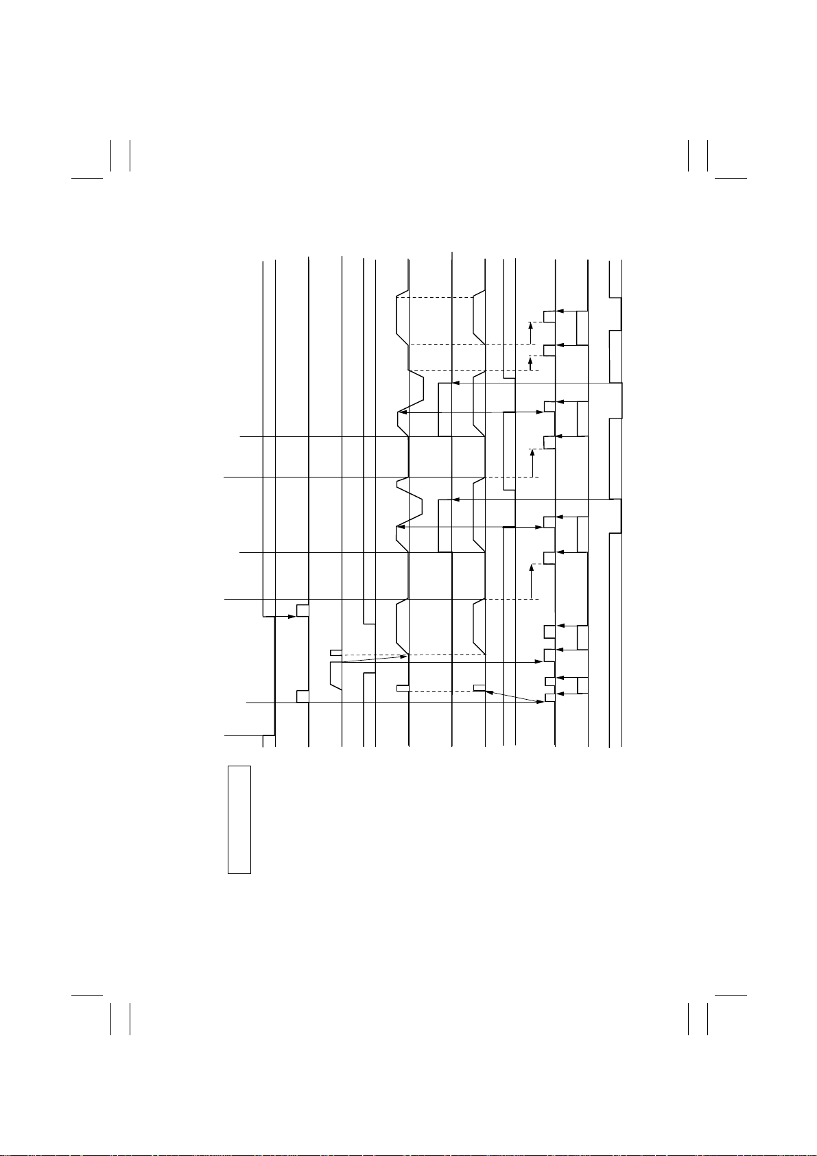
4-1. 1 -Side Or iginal Mode
2nd Copy End
2nd Copy Set
1st Copy End
1 1-Side Original Mode (When Two A4) Documents are Loaded Crosswise
1st Copy Set
Start Key"ON"
Documents Set
H
Empty Sensor
CW : Forward Rotation
CCW: Backward Rotaition
Ascent
Descent
L
PC1
ON
OFF
ON
Take-Up Motor
Pick-Up Motor
M1
OFF
M2
H
L
CW
Main MotorM3Turnover Solenoid
Registration Sensor
PC2
OFF
ON
OFF
SL1
ON
OFF
CW
Scale Drive Motor
Turnover/Exit Motor
M4
OFF
M5
H
L
Scale Drive Sensor
PC12
4652T503CB
H
L
Exit Sensor
PC3
T-8
Page 59

FrameMaker Ver.5.5(PC) DF-331 OPTION FOR 7915/7920
01.02.09
4-2. Mixed Original Mode
2nd Copy End
2nd Copy Set
Ascent
1st Copy Set
2 Mixed Original Mode (When Two A4) Documents are Loaded Crosswise
1st Copy End
Start Key"ON"
Documents Set
H
Empty Sensor
CW : Forward Rotation
CCW: Backward Rotaition
L
PC1
Descent
ON
OFF
Pick-Up Motor
M1
H
ON
OFF
Take-Up Motor
M2
Registration Sensor
L
CW
OFF
Main MotorM3Turnover Solenoid
PC2
ON
OFF
SL1
ON
OFF
CW
Scale Drive Motor
Turnover/Exit Motor
M4
OFF
M5
H
L
Scale Drive Sensor
PC12
4652T504CB
H
L
Exit Sensor
PC3
T-9
Page 60
FrameMaker Ver.5.5(PC) DF-331 OPTION FOR 7915/7920
01.02.09
4-3. 2-Side Original Scanning Mode
TurnoverTurnover
2nd Copy End
2nd Copy Set
1st Page Set
Documents Set
3 2-Side Original Mode (When Two A4) Documents are Loaded Crosswise
1st Copy End
Start Key"ON"
H
Empty Sensor
CW : Forward Rotation
CCW: Backward Rotaition
L
PC1
Ascent
Descent
ON
OFF
Pick-Up Motor
M1
H
ON
OFF
Registration Sensor
Take-Up Motor
M2
L
PC2
T-10
CW
OFF
CCW
Main Motor
M3
ON
ON
OFF
Turnover/Exit Motor
Turnover Solenoid
SL1
OFF
M4
H
L
Turnover Sensor
PC4
CW
OFF
Scale Drive Motor
M5
H
L
Scale Drive Sensor
PC12
4652T505CC
H
L
Exit Sensor
PC3
Page 61

FrameMaker Ver.5.5(PC) DF-331 OPTION FOR 7915/7920
01.02.09
4-4. Single Feed Mode
4 Single Feed Mode (When One A4) Documents are Loaded Crosswise
Copy Start
Documents Set
H
Empty Sensor
CW : Forward Rotation
CCW: Backward Rotaition
L
PC1
ON
OFF
CCW
Take-Up Motor
M2
ON
OFF
CW
M4
OFF
M5
CW
OFF
Main MotorM3Scale Drive Motor
Turnover/Exit Motor
T-11
H
L
Scale Drive Sensor
PC12
H
L
Exit Sensor
PC3
4652T506CB
 Loading...