

Page 1

FrameMaker Ver.5.5(PC) PF-231 OPTION FOR 7915/7920
01.02.09
PF-231
SERVICE MANUAL
10794
Page 2

FrameMaker Ver.5.5(PC) PF-231 OPTION FOR 7915/7920
01.02.09
CONTENTS
GENERAL,
MECHANICAL/ELECTRICAL
1. SPECIFICATIONS ........................................................................................... M-1
2. PARTS IDENTIFICATION ................................ ...............................................M-2
3. CROSS-SECTIONAL VIEW ............................................................................M-2
4. DRIVE SYSTEM ..............................................................................................M-3
5. ELECTRICAL COMPONENTS LAYOUT ........................................................M-3
6. MECHANISM AND CONTROL ............................... ............... ..........................M-4
6-1. Vertical Transport Drive Mechanism ........................................................M-4
6-2. Paper Take-Up Mechanism .....................................................................M-4
6-3. Paper Take-Up Control ............................................................................M-4
6-4. Edge Guides and Trailing Edge Stop ......................................................M-5
6-5. Paper Lifting Plate ...................................................................................M-5
6-6. Double Feed Prevention ..........................................................................M-6
6-7. Drawer-in-Position Detection ................................................................... M-6
6-8. Paper Near Empty Detection ...................................................................M-7
6-9. Paper Empty Detection . ...........................................................................M-7
6-10.Paper Level Indicator LED .......................................................................M-8
6-11.Paper Size Detection ...............................................................................M-9
6-12.Paper Dehumidifying Heater (Option) .....................................................M-10
DIS/REASSEMBLY, ADJUSTMENT
1. DISASSEMBLY ...............................................................................................D-1
1-1. Maintenance Schedule .......................................................... ......... .. .... .. .D-1
1-2. Removal of the Paper Take-Up Roll ........................................................D-2
1-3. Removal of the Separator Roller Assy .....................................................D-3
1-4. Cleaning of the Paper Take-Up Roll ............................................. .... .... .. .D-4
1-5. Cleaning of the Separator Roll .................................................................D-4
1-6. Cleaning of the Vertical Transport Roller/Ro lls ........................................D-4
2. ADJUSTMENT .................................................................................................D-5
2-1. Reference Position Adjustment .................................................. .............D-5
MISFEED DETECTION
1. MISFEED DETECTION ........................................................................ ...........T-1
1-1. Location of Misfeed Detecting Sensors ...................................................T-1
1-2. Misfeed Detection Timing ........................................................................T-2
i
Page 3

FrameMaker Ver.5.5(PC) PF-231 OPTION FOR 7915/7920
01.02.09
GENERAL,
MECHANICAL/ELECTRICAL
Page 4

FrameMaker Ver.5.5(PC) PF-231 OPTION FOR 7915/7920
01.02.09
1. SPECIFICATIONS
Type : Add-on paper source unit
Installation : Mounted beneath Upper Drawer of copier
Type of Copy Paper : Plain paper
Paper Sizes : B5L/C to A3L or 8-1/2 × 11LC to 11 × 17L
Paper Weight :
Registration : Center
Capacity : 500 sheets
Power Requirements : DC24 V ± 10 %, DC5.1 V ± 5 % (supplied from copier)
Max. Power Consumption : 16.8 W
Dimensions : Width ... 535 mm or 21 in
Weight : 8.5 kg or 18-3/4 lbs.
64 to 90 g/m
Depth ... 568 mm or 22-1/4 in
Height ... 127 mm or 5 in
2
or 17 to 24 lbs.
M-1
Page 5
FrameMaker Ver.5.5(PC) PF-231 OPTION FOR 7915/7920
01.02.09
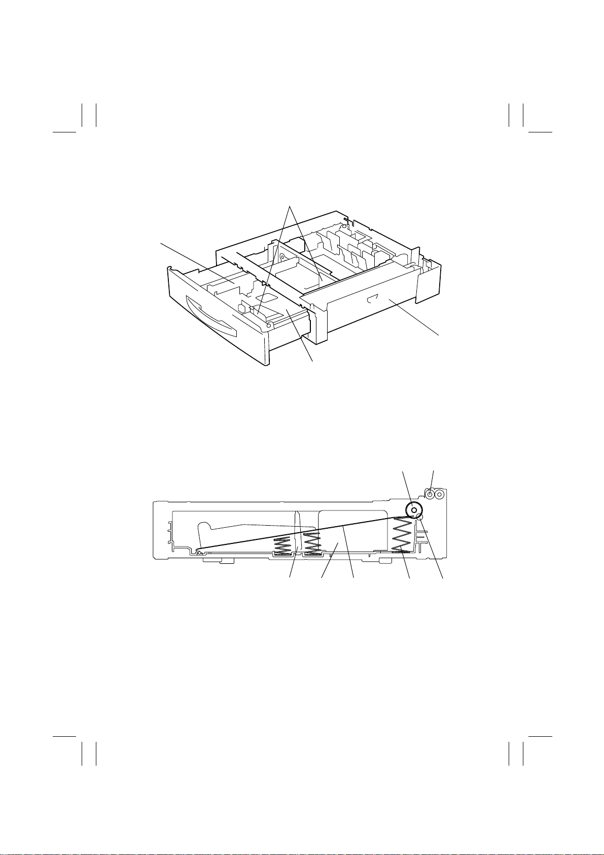
2. PARTS IDENTIFICATION
1
4
2
1. Edge Guides
2. Right Side Door
3. Paper Lifting Plate
4. Trailing Edge Stop
3. CROSS-SECTIONAL VIEW
1. Paper Take-Up Roll
2. Vertical Transport Roller
3. Separator Roll
4. Paper Lifting Spring
5. Paper Lifting Plate
6. Edge Guide
7. Trailing Edge Stop
3
4658M001AB
21
34567
4658M002AA
M-2
Page 6

FrameMaker Ver.5.5(PC) PF-231 OPTION FOR 7915/7920
01.02.09
4. DRIVE SYSTEM
Paper Take-Up
Drive Mechanism
5. ELECTRICAL COMPONENTS LAYOUT
4658M003AA
CL1
M1
PWB-A
PW A
Symbol Name Symbol Name
PWB-A
Control Board
M1
Paper Take-Up Motor
CL1
Paper Take-Up Clutch
UN1
Paper Near Empty Board
PC1
Paper Take-Up Sensor
PC2
Paper Empty Sensor
PC3
Paper Near Empty Sensor
PW C
PW B
PC4
PW D
PC4
PC5
SW A
SW B
SW C
SW D
PC3
PC5
PC2
PC1
4658M004AA
Door Set Sensor
Double Feed Sensor
Paper Size Detection Switch 1
Paper Size Detection Switch 2
Paper Size Detection Switch 3
Drawer Set Switch
UN1
M-3
Page 7

FrameMaker Ver.5.5(PC) PF-231 OPTION FOR 7915/7920
01.02.09
6. MECHANISM AND CONTROL
6-1. Vertical Transport Drive Mechanism
• The Paper Take-Up Motor provides the drive for the Vertical Transport Roller.
Paper Take-Up Motor
M1
Vertical Transport Roller
4658M005AB
6-2. Paper Take-Up Mechanism
• Paper take-up drive is provided by the Paper Take-Up Motor via the Paper Take-Up
Clutch.
Paper Take-Up Clutch
CL1
Paper Take-Up Roll
Paper Take-Up Motor
M1
Separator Roll
4658M006AB
6-3. Paper Take-Up Control
• The Paper Take-Up Clutch is energized and deenergized by the signals output from pins
13 and 14 of PJ3A on the Control Board.
Start Key ON
Paper Tak e-Up Motor
M1
Paper Tak e-Up Clutch
CL1
Paper Tak e-Up Sensor
PC1
ON
OFF
ON
OFF
H
L
4658M502CA
M-4
Page 8

FrameMaker Ver.5.5(PC) PF-231 OPTION FOR 7915/7920
01.02.09
6-4. Edge Guides and Trailing Edge Stop
• The Trailing Edge Stop can be removed and reinstalled to the specified position corresponding to the size of the paper to be loaded.
• The Edge Guides can be slid to the exact size of the paper to be loaded.
Trailing Edge Stop
4658M007AA 4658M008AA
Edge Guides
6-5. Paper Lifting Plate
• The Paper Lifting Plate is locked into position when it is pressed down. It is unlocked
automatically when the drawer is slid into the unit.
• The Paper Lifting Plate is pushed upward by the Paper Lifting Springs at all times.
Paper Lifting Spring
Paper Lifting Plate
4658M009AB
M-5
Page 9

FrameMaker Ver.5.5(PC) PF-231 OPTION FOR 7915/7920
01.02.09
6-6. Double Feed Prevention
• If a sheet of paper reaches the Double Feed Sensor earlier than a predetermined period
of time after the paper take-up sequence has been started, the sequence is temporarily
halted. After an adequate period of time thereafter, the paper take-up sequence is
restarted again so that a given distance is provided between sheets of paper.
Paper Path
Vertical Transport Roller
Paper Take-Up Roll
Paper
Double Feed Sensor PC5
4658M503AA
6-7. Drawer-in-Position Detection
• When the drawer is slid into the unit, the Drawer Set Switch is actuated, allowing the
copier to determine that the drawer has been slid into position.
Drawer Set Switch SW D
4658M010AA
M-6
Page 10

FrameMaker Ver.5.5(PC) PF-231 OPTION FOR 7915/7920
01.02.09
6-8. Paper Near Empty Detection
• The Paper-Near-Empty Sensor detects a paper-near-empty condition in the drawer.
• A given number of sheets of paper has been determined as the basis for detection of a
paper-near-empty condition.
Predetermined No. of Sheets (Paper Level)
Paper-Near-Empty Detected 50 ± 30 sheets
Paper Near Empty Sensor PC3
Paper
4658M011AA
6-9. Paper Empty Detection
• The Paper Empty Sensor detects a paper-empty condition in the drawer.
Paper Empty Sensor PC2
4658M012AA
Paper Lifting Plate
4658M504AA
4658M505AA
M-7
Page 11

FrameMaker Ver.5.5(PC) PF-231 OPTION FOR 7915/7920
01.02.09
6-10. Paper Level Indicator LED
• An LED is used to indicate different levels of the paper loaded in the drawer.
Drawer Condition LED Indication
Open ON
Paper empty ON
Paper near empty Blinking
Paper loaded OFF
LED
M-8
4658M013AA
Page 12

FrameMaker Ver.5.5(PC) PF-231 OPTION FOR 7915/7920
01.02.09
6-11. Paper Size Detection
• When the drawer is slid into the unit, some of the contacts of the three Paper Size
Detecting Switches are closed according to the position of the Edge Guides and Trailing
Edge Stop. The combination of the open and closed states of these contacts of the
Paper Size Detecting Switches determines a specific paper size.
SW A SW B SW C
FD1 FD2 FD3 FD4 FD5 FD6 FD7 FD8 FD9 FD10 FD11 CD1
Leager L H H H H H H H H H H H L
A3L LHHHHHHHH H H L
B4L HLHHHHHHH H H H
11 × 14L HHL H HHHHH H H L
Legal L H H L H H H H H H H H H
FLS HHHLHHHHH H H H
A4L HHHHLHHHH H H H
Letter L H H H H H L H H H H H H
B5L HHHHHHLHH H H H
Letter C HHHHHHHLH H H L
A4C HHHHHHHHL H H L
G, Letter C HHHHHHHHH L H H
B5C HHHHHHHHH H L H
✽
ON: L, OFF: H
Trailing Edge Stop
Paper Size Detection Switch 1
SW A
Paper Size Detection Switch 2
SW B
Paper Size Detection Switch 3
SW C
4658M014AB
Edge Guides
M-9
Page 13

FrameMaker Ver.5.5(PC) PF-231 OPTION FOR 7915/7920
01.02.09
6-12. Paper Dehumidifying Heater (Option)
• The Paper Dehumidifying Heater prevents an image transfer failure from occurring,
caused by paper that gets damp under changing environmental conditions (temperature
and humidity).
Conditions
Power cord plugged in ON
Power Switch OFF ON
Sleep ON
Copy cycle OFF
Predrive (Imaging Unit Motor energized) OFF
Paper Dehumidifying Heater
(Heater Switch ON)
M-10
Page 14

FrameMaker Ver.5.5(PC) PF-231 OPTION FOR 7915/7920
01.02.09
DIS/REASSEMBLY,
ADJUSTMENT
Page 15

FrameMaker Ver.5.5(PC) PF-231 OPTION FOR 7915/7920
01.02.09
1. DISASSEMBLY
1-1. Maintenance Schedule
• To ensure good copies and an extended service life of the this Unit, it is recommended
that the maintenance jobs described in this schedule be carried out.
Maintenance
PM Parts
Paper Take-Up
Roll
Separator Roll
Assy
Vertical
Transport
Roller
Vertical
Transport Rolls
K=1,000 sheets
✽
The above maintenance schedule is to be based on the value of Counter/Life.
✽
Cleaning (indicated by “❍” in the above schedule) should be performed when a paper
transport failure occurs.
✽
The Paper Take-Up Roll and Separator Roll Assy should be replaced at the same time.
✽
The above information is subject to change without notice.
Schedule Cycle (K)
Clean Replace
❍
❍
❍
❍
200
200 111T-5010 1
––1
––9
Tools
Used for
Cleaning
Cloth,
alcohol
Parts No. Q T Y
111T51010 1
Counter/
Life
2nd.
3rd.
4th.
Reference
Page
☞
☞
☞
☞
D-2
D-3
D-4
D-4
D-1
Page 16

FrameMaker Ver.5.5(PC) PF-231 OPTION FOR 7915/7920
01.02.09
1-2. Removal of th e Paper Take-Up Roll
1. Slide out the drawer.
4658D001AA
2. Lock the Paper Lifting Plate.
3. Snap off one C-clip from the Paper Take-Up Roll
assy.
4. Move the Paper Take-Up Roll assy toward the rear
of the unit and lift it off the bushing at the front.
4658D008AA
5. Snap off one C-clip and remove the Paper TakeUp Roll.
4658D009AA
D-2
Page 17

FrameMaker Ver.5.5(PC) PF-231 OPTION FOR 7915/7920
01.02.09
1-3. Removal of the Separator Roller Assy
1. Slide out the drawer.
4658D001AA
2. Remove two screws and the Separator Roll mounting bracket assy.
4658D002AA
3. Remove the rubber stopper, shaft, spring, and the
guide plate. Then, remove the Separator Roll fixing
bracket assy.
4658D003AA
4658D004AA
NOTE
• At reinstallation, make sure that the rubber stopper
is on the rear side of the unit.
4. Snap off one E-ring and remove the Separator Roll
assy.
D-3
Page 18

FrameMaker Ver.5.5(PC) PF-231 OPTION FOR 7915/7920
01.02.09
1-4. Cleaning of the Paper Take-Up Roll
1. Slide out the drawer.
2. Dampen a soft cloth with alcohol and wipe the surface of the Paper Take-Up Roll clean of dirt.
4658D005AA
1-5. Cleaning of the Separator Roll
1. Slide out the drawer.
2. Remove two screws and the Separator Roll mounting bracket assy.
3. Dampen a soft cloth with alcohol and wipe the surface of the Separator Roll clean of dirt.
4658D006AA
1-6. Cleaning of the Vertical Transport Roller/Rolls
1. Slide out the drawer.
2. Open the Right Side Door.
3. Dampen a soft cloth with alcohol and, turning the
knob, wipe the surfaces of the Vertical Transport
Roller/Rolls clean of dirt.
4658D007AA
D-4
Page 19

FrameMaker Ver.5.5(PC) PF-231 OPTION FOR 7915/7920
01.02.09
2. ADJUSTMENT
2-1. Reference Position Adjustment
1. Press the Utility key and touch “Meter Count.”
2. Press the following keys in this order to show the
Tech. Rep. mode screen: Stop → 0 → 0 → Stop →
0 → 1.
3. Touch “Machine Adjust.”
4658D507CA
4. Touch “PRT Area.”
4658D508CA
Feeding
Direction
5. Touch “Left Margin.”
4658D509CA
6. Touch “2nd.”
NOTE
• Use the same procedures that follow for “3rd” and
“4th.”
4658D510CA
7. Press the Start key to produce a test print.
8. Measure dimension A to determine if it falls within
A
the specified range.
✽
Specifications: 3.0 ± 1.0 mm
9. Using or key, input the difference
between the measured value of dimension A and
the specifications.
4658D505AA
10. Produce another test print and make a check
again.
D-5
Page 20

FrameMaker Ver.5.5(PC) PF-231 OPTION FOR 7915/7920
01.02.09
11. If the specifications are not met, perform the following steps to make an adjustment.
12. Unload paper from the drawer and loosen the two
screws of the drawer.
C4658U024AA
13. Watching the scale on the adjusting plate inside
the drawer, move the Edge Guide as necessary.
14. Tighten the two screws. Then, produce a test print
to check again.
C4658U025AA
D-6
Page 21

FrameMaker Ver.5.5(PC) PF-231 OPTION FOR 7915/7920
01.02.09
MISFEED DETECTION
Page 22

FrameMaker Ver.5.5(PC) PF-231 OPTION FOR 7915/7920
01.02.09
1. MISFEED DETECTION
1-1. Location of Misfeed Detecting Sensors
• The explanations given hereunder are based on a paper feed unit configuration of the
2nd Drawer (standard) + 3rd Drawer + 4th Drawer as illustrated below.
Synchronizing Roller Sensor PC17
Paper Take-Up Sensor of the 2nd Drawer PC101
Paper Take-Up Sensor of the 3rd Drawer PC1
Paper Take-Up Sensor of the 4th Drawer PC1
4658T501AA
T-1
Page 23

FrameMaker Ver.5.5(PC) PF-231 OPTION FOR 7915/7920
01.02.09
1-2. Misfeed Detection Timing
• The following lists the types of misfeed detection and detection timings for different misfeed locations.
• The symbol “L” (for the leading edge) and “T” (for the trailing edge) given in ( ) indicate
the particular edge of the paper detected by the sensor.
Type Detection Start Detection
Paper left
Paper take-up failure in
the 2nd Drawer
Paper take-up failure in
the 3rd Drawer
Paper take-up failure in
the 4th Drawer
Misfeed in the 2nd
Drawer vertical transport
section
Misfeed in the 3rd Drawer
vertical transport section
Misfeed in the 4th Drawer
vertical transport section
Misfeed caused by a size
error
Power Switch ON
Misfeed reset
Paper Take-Up Motor of the
2nd Drawer energized
Paper Take-Up Motor of the
3rd Drawer energized
Paper Take-Up Motor of the
4th Drawer energized
Paper Take-Up Sensor of the
2nd Drawer (L)
Paper Take-Up Sensor of the
3rd Drawer (L)
Paper Take-Up Sensor of the
4th Drawer (L)
Paper Take-Up Sensor of the
2nd Drawer (L)
Paper Take-Up Sensor of the
3rd Drawer (L)
Paper Take-Up Sensor of the
4th Drawer (L)
Paper Take-Up Sensor of
each drawer ON
Paper Take-Up Sensor of the
2nd Drawer (L)
Paper Take-Up Sensor of the
3rd Drawer (L)
Paper Take-Up Sensor of the
4th Drawer (L)
Synchronizing Roller Sensor
(L)
Paper Take-Up Sensor of the
2nd Drawer (L)
Paper Take-Up Sensor of the
3rd Drawer (L)
Paper Take-Up Sensor of the
2nd Drawer (T)
Paper Take-Up Sensor of the
3rd Drawer (T)
Paper Take-Up Sensor of the
4th Drawer (T)
T-2
 Loading...