

Page 1

7832
SERVICE HANDBOOK
Dec. 2000
Ver. 1.0
KONICA CORPORATION
TECHNOLOGY SUPPORT CENTER
TOKYO JAPAN
KCS783210
Page 2

INDEX (GENERAL)
GENERAL
MECHANICAL/ELECTRICAL
Page 3

Blank page
Page 4

GENERAL
Page 5

Blank page
Page 6

CONTENTS
1. SAFETY INFORMATION .................................................................................G-1
1-1. Laser Safety .............................................................................................G-1
1-2. Internal Laser Radiation ...........................................................................G-1
1-3. CDRH Regulations ..................................................................................G-2
1-4. Laser Safety Label ...................................................................................G-4
1-5. Location of Laser Warning Labels ...........................................................G-4
2. SPECIFICATIONS ...........................................................................................G-7
3. PRECAUTIONS FOR INSTALLATION ............................................................G-10
4. PRECAUTIONS FOR USE ..............................................................................G-11
5. HANDLING OF THE CONSUMABLES ...........................................................G-12
6. OTHER PRECAUTIONS .................................................................................G-12
7. SYSTEM OPTIONS .........................................................................................G-13
8. HIGHLIGHTS ...................................................................................................G-14
i
Page 7

Blank page
Page 8

1. SAFETY INFORMATION
1-1. Laser Safety
This is a digital copier which operates by means of a laser. There is no possibility of danger
from the laser, provided the copier is operated according to the instructions in this manual.
Since radiation emitted by the laser is completely confined within protective housing, the
laser beam cannot escape from the copier during any phase of user operation.
This copier is certified as a Class 1 laser product. This means the copier does not produce
hazardous laser radiation.
1-2. Internal Laser Radiation
Maximum Average Radiat Power: 78.1 µW at the laser aperture of the upper print head
assy.
Wavelength: 675-695 nm
This product employs a Class
The Laser Diode and the Scanning Polygon Mirror are Incorporated in the print head assy.
The print head assy is NOT A FIELD SERVICE ITEM.
Therefore, the print head assy should not be opened under any circumstances.
III
b Laser Diode that emits a laser beam.
Upper Print Head Assy
G-1
Lower Print Head Assy
1179O070AA
Page 9

1-3. CDRH Regulations
For the United States
This copier is certified as a Class I Laser product under Radiation Performance Standard
according to the Food, Drug and Cosmetic Act of 1990. Compliance is mandatory for Laser
products marketed in the United States and is reported to the Center for Devices and
Radiological Health (CDRH) of the U.S. Food and Drug Administration of the U.S. Department of Health and Human Services (DHHS). This means that the device does not produce
hazardous laser radiation.
The label shown to page G-4 indicates compliance with the CDRH regulations and must be
attached to laser products marketed in the United States.
CAUTION:
Use of controls, adjustments or performance of procedures other than those specified in
this manual may result in hazardous radiation exposure.
This is a semiconductor laser. The maximum power of the laser diode is 35 mW and the
wavelength is 675-695 nm.
For European Users
CAUTION:
Use of controls, adjustments or performance of procedures other than those specified in
this manual may result in hazardous radiation exposure.
This is a semiconductor laser. The maximum power of the laser diode is 35 mW and the
wavelength is 675-695 nm.
For Denmark Users
ADVARSEL
Laserstråling ved åbning, når sikkerhedsafbrydere er ude af funktion. Undgå udsættelse
for stråling. Klasse 1 laser produkt der opfylder IEC60825 sikkerheds kravene.
Dansk: Dette er en halvlederlaser. Laserdiodens højeste styrke er 35 mW og
bølgelængden er 675-695 nm.
G-2
Page 10

For Finland, Sweden Users
LOUKAN 1 LASERLAITE
KLASS 1 LASER APPARAT
VAROITUS!
Laitteen Käyttäminen muulla kuin tässä käyttöohjeessa mainitulla tavalla saattaa altistaa
käyttäjän turvallisuusluokan 1 ylittävälle lasersäteilylle.
Tämä on puolijohdelaser. Laserdiodin suurin teho on 35 mW ja aallonpituus on 675-695
nm.
VARNING!
Om apparaten används på annat sätt än i denna bruksanvisning specificerats, kan användaren utsättas för laserstrålning, som överskrider gränsen för laserklass 1.
Det här är en halvledarlaser. Den maximala effekten för laserdioden är 35 mW och
våglängden är 675-695 nm.
VARO!
Avattaessa ja suojalukitus ohitettaessa olet alttiina lasersäteilylle. Älä katso säteeseen.
VARNING!
Laserstrålning när denna del är öppnad och spärren är urkopplad. Betrakta ej strålen.
For Norway Users
ADVERSEL
Dersom apparatet brukes på annen måte enn spesifisert i denne bruksanvisning, kan
brukeren utsettes for laserstråling som overskrider grensen for laser klass 1.
Dette en halvleder laser. Maksimal effekt till laserdiode er 35 mW og bølgelengde er 675695 nm.
G-3
Page 11
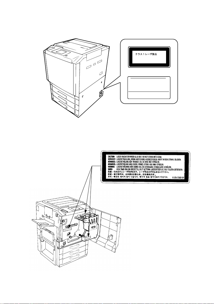
1-4. Laser Safety Label
A laser safety labels is attached to the outside of the copier shown below.
For Europe
CLASS 1 LASER PRODUCT
LASER KLASSE 1 PRODUKT
For United States
KONICA CORPORATION
1-26-2, Shinjuku Nomura Building No.26-2,
Nishishinjuku 1-chome, Shinjuku-ku, Tokyo 163-0512, Japan
MANUFACTURED :
THIS PRODUCT COMPLIES WITH 21 CFR
CHAPTER I , SUBCHAPTER J .
1-5. Location of Laser Warning Labels
Inside the Copier (Front)
1154-7411-01
1179M037CA
1179O075AA
G-4
1179O077AA
Page 12

Internal Right Side View
1179O080AA
1179O079AA
Rear Side View
1179O069AB
1179O076AA
G-5
1179O078AA
1179O078AA
Page 13

ALL Areas
Danger of explosion if battery is incorrectly replaced.
CAUTION
Replace only with the same or equivalent type
recommended by the manufacturer.
Dispose of used batteries according
to the manufacturer’s instructions.
Denmark only
Norway only
Sweden only
Finland only
ADVARSEL!
Lithiumbatteri - Eksplosionsfare ved fejlagtig håndtering
Udskiftning må kun ske med batteri
af samme fabrikat og type.
Levér det brugte batteri tilbage til leverandøren.
ADVARSEL
Eksplosjonsfare ved feilaktig skifte av batteri.
Benytt samme batteritype eller en tilsvarende
type anbefalt av apparatfabrikanten.
Brukte batterier kasseres i henhold til fabrikantens
instruksjoner.
VARNING
Explosionsfara vid felaktigt batteribyte.
Använd samma batterityp eller en ekvivalent
typ som rekommenderas av apparattillverkaren.
Kassera använt batteri enligt fabrikantens
instruktion.
VAROlTUS
Paristo voi räjähtää, jos se on virheellisesti asennettu.
Vaihda paristo ainoastaan laitevalmistajan suosittelemaan
tyyppiin. Hävitä Käytetty paristo valmistajan ohjeiden
mukaisesti.
G-6
Page 14

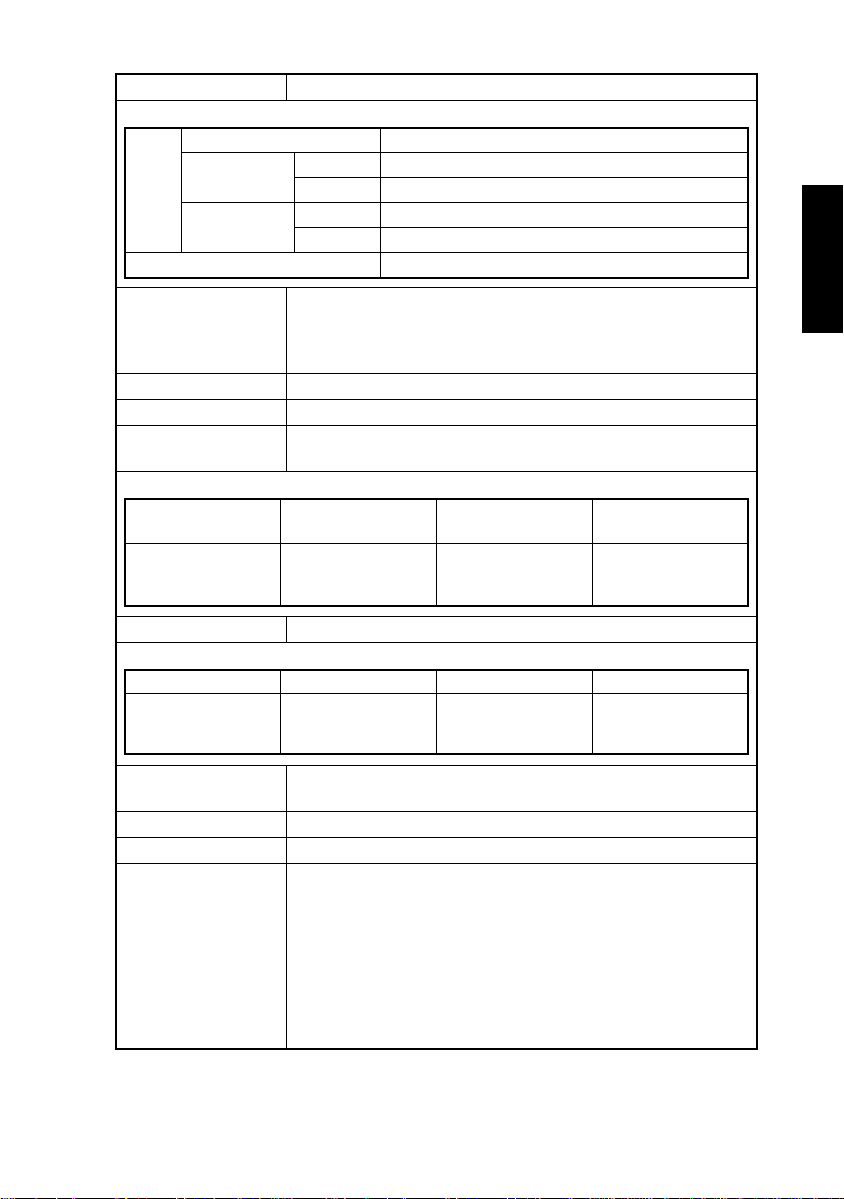
2. SPECIFICATIONS
Type Freestanding
Platen Type Stationary
Original Scanning Sequential scanning of different colors with a reduction-type color
CCD (RGB 3 lines each comprising 7,500 pixels)
Scanning Density 600 dpi × 600 dpi
Print Density 1800 dpi equivalent × 600 dpi
Copying System Electrostatic dry-powdered image transfer to plain paper
Paper Feeding System Four-way system
• Multi Bypass Table: 90 sheets of paper
• Middle Drawer (universal type): 250 sheets of paper
• Upper and Lower Drawer (fixed-size type): Each holding up to
500 sheets of paper
Exposure System Laser Diode 1 + Polygon Mirror
Developing System Micro-Toning System
Charging System Scorotron system (single-wire DC (–) + grid mesh)
Paper Attraction
System
Image Transfer
System
Paper Separating
System
Transfer Film Cleaning
System
PC Drum Cleaning
System
Ozone Removal
System
Fusing System Two lamp-heated rollers
Transfer Film Charge
Neutralizing
PC Drum OPC-MLII (Organic Photoconductor)
Types of Originals Sheet, book, and three-dimensional objects weighing up to 2 kg.
Maximum Size of
Original
Copy Paper Size Multi Bypass Table: Metric - A3 wide L (305 mm × 457 mm) to
Static charge attraction system (corotron charger + attraction
roller + backup mechanism)
Static image transfer system (corotron charger + backup mecha-
nism)
Static charge separating system (corotron charger + separator
fingers + film pressure mechanism)
Fur Brush (bias 0 or 360 V) + Oil Roller (900 V)
Cleaning Blade + PC Drum Charge Neutralizing Corona
Ozone Filters
Static charge neutralizing (corotron charger)
Metric - A3L
Inch - 11 × 17L
A5L, A6 thick paper
Inch - 12 × 18 to 5-1/2 × 8-1/2L,
4 × 6 thick paper
Upper/Middle/Lower Drawer: Metric - A3L to A5L
Inch - 11 × 17L to 5-1/2 × 8-1/2L
G-7
Page 15

Copy Paper Type:
1st to 3rd Drawers
(automatic feeding)
Plain paper (64 to 90 g/m2)
Translucent paper ——
OHP transparencies (dedicated) —
Thick paper 1 (91 to 128 g/m
Thick paper 2 (129 to 209 g/m
Copy paper
A6 thick paper (Metric)
4 × 6 thick paper (Inch)
Recycled paper ——
Max. (width × length mm) 297 × 432 mm 305 × 457 mm
Min. (width × length mm) 140 × 182 mm
Dimensions
❍
: Reliably fed —: Unreliably fed
✽
1: Reliably fed if 90 sheets or less.
✽
2: Reliably fed if 40 sheets or less.
✽
3: Reliably fed if 30 sheets or less.
2
)
2
)
❍❍ ✽
—
—
—
Multi Bypass Table
1
2
❍ ✽
2
❍ ✽
2
❍ ✽
3
❍ ✽
140 × 182 mm
[A6 thick paper
105 × 148 mm (Metric)
4 × 6 thick paper
102 × 152 mm (Inch)]
Warming-up Time Approx. 9 min. at ambient temperature of 20 °C and rated source
voltage
Warming-up Time
60 sec. or less
After Energy Saver
Mode
First Copy Time (Upper Drawer, ×1.000, manual color selection)
Area Paper Size Full Color Mono Color
Inch 8-1/2 × 11C
Metric A4C
21 sec. 10 sec.
Copying Speed for Multi-Copy Cycle (Upper Drawer, ×1.000) (copies/min.)
Area Paper Size Full Color Mono Color
A3L
Metric
Inch
B4L
A4L
B5L
A4C
A5L
11 × 17L
8-1/2 × 11L
8-1/2 × 11C
5-1/2 × 8-1/2L
416
832B5C
416
832
G-8
Page 16
Multiple Copies 1 to 99 copies (count-down system)
Zoom Ratios
Full size
Fixed
Enlargement
Reduction
Variable
Inch
Metric
Inch
Metric
×
1.214, ×1.294, ×2.000
×
1.154, ×1.224, ×1.414
×
0.647, ×0.733, ×0.785
×
0.707, ×0.816, ×0.866
×
0.250 to ×6.000 (in 0.001 increments)
1.000
×
Void Image Width Leading edge: 5 mm
Trailing edge: 4 mm
Front/rear edge: 3 mm [4 × 6 thick paper (Inch), A6 thick paper
(Metric); 5 mm]
Lens Through lens (F = 5, f = 79 mm)
Light Source Halogen frost tube lamp
Fusing Temperature Upper Fusing Roller surface temperature: 160 °C
Lower Fusing Roller surface temperature: 170 °C
Power/Current Consumption
Exposure Lamp
(Rating)
70 V
150 W
Fusing Roller Heater
Lamp (Rating)
120 V, 220-240 V
Upper: 650 W
Lower: 400 W
Max. Power
Consumption
1500 W 13 A/7 A
Max. Current
Consumption
Power Requirements 120 V, 220-240 V; 50 Hz/60 Hz
Environmental Conditions
Temperature Humidity Ambient Illumination Levelness
10 to 32 °C with a
fluctuation of 10 °C or
less per hour
15 to 85 % with a fluctuation of 10 % or less
per hour
3000 lx or less 1° or less
Dimensions 640 (W) × 765 (D) × 994 (H) mm (H: Up to Original Glass surface)
640 (W) × 765 (D) × 1024 (H’) mm (H’: Up to Original Cover)
Weight 215 kg
Standard Accessories Exit Tray, Operator’s Manual Holder
Options • Duplexing Document Feeder
DF-724
• ADF Kit 7823
• 10 Bin Staple Sorter ST-724
• 10 Bin Sorter ST-723
• Printer Controller Fiery Z4
08C-M
• VI Kit VI-631
• Large Capacity Cassette
LT-723
• Duplex Unit AD-723
• Printer Controller Fiery X3e
08C-M
• VI Kit VI-632
G-9
Page 17

3. PRECAUTIONS FOR INSTALLATION
Installation Site
To ensure safety and utmost performance of the copier, the copier should NOT be used in
a place:
• Where it will be subjected to extremely high or low temperature or humidity.
• Which is exposed to direct sunlight.
• Which is in the direct air stream of an air conditioner, heater or ventilator.
• Which puts the operator in the direct stream of exhaust from the copier.
• Which has poor ventilation.
• Where ammonia gas might be generated.
• Which does not have a stable, level floor.
• Where it will be subjected to sudden fluctuations in either temperature or humidity. If a
cold room is quickly heated, condensation forms inside the copier, resulting in blank
spots in the copy.
• Which is near any kind of heating device.
• Where it may be splashed with water.
• Which is dirty or where it will receive undue vibration.
• Which is near volatile flammables or curtains.
Power Source
Use an outlet with a capacity of 120 V/13 A, or 220-240 V/7 A or more.
• If any other electrical equipment is sourced from the same power outlet, make sure that
the capacity of the outlet is not exceeded.
• Use a power source with little voltage fluctuation.
• Never connect by means of a multiple socket any other appliances or machines to the
outlet being used for the copier.
• Make the following checks at frequent intervals:
✽
Is the power plug abnormally hot?
✽
Are there any cracks or scrapes in the cord?
✽
Has the power plug been inserted fully into the outlet?
✽
Does something, including the copier itself, ride on the power cord?
• Ensure that the copier does not ride on the power cord or communications cable of other
electrical equipment, and that it does not become wedged into or underneath the mechanism.
Grounding
To prevent receiving electrical shocks in the case of electrical leakage, always ground the
copier.
• Connect the grounding wire to:
✽
The ground terminal of the outlet.
✽
A grounding contact which complies with the local electrical standards.
• Never connect the grounding wire to a gas pipe, the grounding wire for a telephone, or a
water pipe.
G-10
Page 18

4. PRECAUTIONS FOR USE
To ensure that the copier is used in an optimum condition, observe the following precautions.
• Never place a heavy object on the copier or subject the copier to shocks.
• Insert the power plug all the way into the outlet.
• Do not attempt to remove any panel or cover which is secured while the copier is making
copies.
• Do not turn OFF the Power Switch while the copier is making copies.
• Provide good ventilation when making a large number of copies continuously.
• Never use flammable sprays near the copier.
• If the copier becomes inordinately hot or produces abnormal noise, turn it OFF and
unplug it.
• Do not turn ON the Power Switch at the same time when you plug the power cord into
the outlet.
• When unplugging the power cord, do not pull on the cord; hold the plug and pull it out.
• Do not bring any magnetized object near the copier.
• Do not place a vase or vessel containing water on the copier.
• Be sure to turn OFF the Power Switch at the end of the workday or upon power failure.
• Use care not to drop paper clips, staples, or other small pieces of metal into the copier.
Operating Environment
The operating environmental requirements of the copier are as follows.
• Temperature: 10 °C to 32 °C with a fluctuation of 10 °C per hour
• Humidity: 15 % to 85 % RH with a fluctuation of 10 % per hour
Power Requirements
The power source voltage requirements are as follows.
• Voltage Fluctuation: AC120 V, 220-240 V
• Frequency Fluctuation: 50/60 Hz ±0.3 %
±10 % (Copying performance assured)
–15 % (Paper feeding performance assured)
G-11
Page 19

5. HANDLING OF THE CONSUMABLES
Before using any consumables, always read the label on its container carefully.
• Use the right toner. The applicable copier model name is indicated on the Toner Bottle.
• Paper is apt to be easily damaged by dampness. To prevent absorption of moisture,
store paper, which has been removed from its wrapper but not loaded into the Drawer, in
a sealed plastic bag in a cool, dark place.
• Keep consumables out of the reach of children.
• Do not touch the PC Drum with bare hands.
• Store the paper, toner, and other consumables in a place free from direct sunlight and
away from any heating apparatus.
• The same sized paper is of two kinds, short grain and long grain. Short grain paper
should only be fed through the copier crosswise, long grain paper should only be fed
lengthwise.
• If your hands become soiled with toner, wash them with soap and water immediately.
• Do not throw away any used consumables (PC Drum, starter, toner, etc.). They are to be
collected.
NOTE
Do not burn, bury in the ground, or throw into the water any consumables (PC Drum,
starter, toner, etc.).
6. OTHER PRECAUTIONS
The Printerhead of this copier uses a laser diode that emits a laser beam. Use the following
precautions when performing service jobs at the users’ premises.
• When a service job needs to be performed in the laser beam path, such as when working
around the printerhead and PC Drum, be sure first to turn the copier OFF.
• If the job requires that the power cord be left plugged in, observe the following precautions
1. Take off your watch, ring, and any other reflective object and wear laser protective gog-
gles.
2. At the job site, select a place that is as far as possible away from the users and that is
enclosed by walls.
3. Do not bring a highly reflective tool into the laser beam path during the service job.
G-12
Page 20

7. SYSTEM OPTIONS
1
1151O007AA
6
1144O184AA
5
1139O0020A
1. Duplexing Document Feeder DF-724
2. Large Capacity Cassette LT-723
3. Printer Controller Fiery X3e 08C-M
4. Printer Controller Fiery Z4 08C-M
1154O028AA
1179O014AA
1179M558AA
1179O046AA
5. 10 Bin Staple Sorter ST-724
10 Bin Sorter ST-723
6. Duplex Unit AD-723
2
3
4
G-13
Page 21

8. HIGHLIGHTS
1. High-quality image reproduction
• HYPER DASH LIMOS & FEET processing.
2. Greater ease of operation
• Employs a touch panel display.
• Equipped with two image quality adjustment modes, “Color Adjust Mode (Basic)” and
“Color Adjust Mode (Professional).”
• Photo mode and Postcard
• ACS mode
• Capable of automatically determine the type of the original, whether it is a photo, text, or
a map, to set the most appropriate copy function.
• Color Auto Exposure function
• Copy track function by means of specific access codes that can be entered from the 10-
Key Pad.
3. Higher productivity
• Efficient, high-speed 2-sided printing with four sheets of paper being resident along the
paper path inside the copier.
4. Environmental consciousness
• Fuser oil recycling system
• Two-sheet attraction for a lower system speed and lower operating noise without sacrific-
ing productivity.
• The reduced number of drive-transmitting parts means a reduced number of noise
sources.
• Lower concentration of ozone by means of the Ozone Filter.
• Uses recyclable plastic materials.
• No harmful substances are used.
5. Better serviceability
• Unitized construction for greater serviceability
• Version upgraded by a flash memory card
G-14
Page 22

MECHANICAL/
ELECTRICAL
Page 23

CONTENTS
1. CROSS-SECTIONAL VIEW AND PAPER PATH ............................................M-1
2. COPY PROCESS ............................................................................................M-2
3. DRIVE SYSTEM ..............................................................................................M-5
4. OPERATING SEQUENCE ..............................................................................M-6
5. CONTROL BLOCK DIAGRAM ........................................................................M-13
6. IMAGE STABILIZATION SYSTEM ..................................................................M-14
6-1. Image Stabilization System Overview .....................................................M-14
6-2. Image Stabilization System Control .........................................................M-15
(1) V detection during multi-copy cycles ...............................................M-16
(2) AIDC detection during multi-copy cycles .........................................M-16
(3) Evaluation of whether or not to run image stabilization ...................M-16
(4) AIDC background adjustment ..........................................................M-16
(5) LDC detection ..................................................................................M-17
(6) Image formation Vg/Vb setting ........................................................M-17
(7) Series gradation detection ...............................................................M-17
(8) Density conversion by density table ................................................M-18
7. PC DRUM SECTION .......................................................................................M-19
7-1. Grounding of the PC Drum ......................................................................M-19
7-2. PC Drum Drive Mechanism .....................................................................M-20
7-3. PC Drum Temperature Control ................................................................M-21
8. PC DRUM CHARGING SECTION ...................................................................M-22
8-1. PC Drum Charge Corona ON/OFF Control .............................................M-22
8-2. PC Drum Charge Corona Wire Cleaning Mechanism .............................M-23
8-3. PC Drum Charge Section Ozone Filter ....................................................M-24
9. IMAGE READER (IR) SECTION .....................................................................M-25
9-1. IR Image Processing ...............................................................................M-26
9-2. CCD Sensor .............................................................................................M-35
9-3. Exposure Components Section ...............................................................M-36
9-4. Exposure Lamp Control ...........................................................................M-37
9-5. Scanner and 2nd/3rd Mirrors Carriage Movement Mechanism ...............M-38
9-6. Scanner Motor Drive Control ...................................................................M-39
9-7. IR Section Cooling Fan Motor Mechanism ..............................................M-41
9-8. Original Size Detecting Section ...............................................................M-42
(1) Original Size Detecting Sensors ......................................................M-42
(2) Original Size Detection Timing ........................................................M-43
(3) Determining Original Size ................................................................M-44
10. PRINTERHEAD (PH) SECTION ......................................................................M-46
10-1.Image Processing Block Diagram ...........................................................M-47
10-2.Laser Exposure Process .........................................................................M-50
10-3.Laser Emission Timing (SOS Signal) ......................................................M-51
10-4.Laser Emission Area ...............................................................................M-52
10-5.HYPER DASH LIMOS and FEET ............................................................ M-53
11. DEVELOPING UNIT SECTION .......................................................................M-54
11-1.Developing Unit Drive Mechanism ..........................................................M-55
11-2.Developer Flow ........................................................................................M-57
11-3.Developing Bias and ATDC Bias .............................................................M-59
i
Page 24

11-4.ATDC Sensor ..........................................................................................M-60
11-5.AIDC Sensor ............................................................................................M-62
11-6.Black Toner Replenishing Control ...........................................................M-63
11-7.Auxiliary Toner Replenishing Mechanism ...............................................M-64
11-8.Toner Suction Fan Motor ......................................................................... M-65
11-9.Pre-Image Transfer Corona .....................................................................M-66
11-10.Pre-Image Transfer Corona Output Control ..........................................M-67
11-11.Pre-Image Transfer Corona ON/OFF Control .......................................M-67
11-12.Pre-Image Transfer Corona Output Stabilization Control ......................M-67
12. TONER HOPPER SECTION ...........................................................................M-68
12-1.Toner Replenishing Mechanism ..............................................................M-69
12-2.Toner Empty Detection Control ...............................................................M-71
13. PAPER TAKE-UP/FEED SECTION ................................................................M-72
13-1.Universal Tray Paper Size Detection Mechanism ...................................M-73
13-2.Drawer-in-Position Detection Mechanism ...............................................M-75
13-3.Drawer Paper Lifting/Lowering Mechanism .............................................M-76
13-4.Paper Empty Detection Mechanism ........................................................M-78
13-5.Paper Take-Up Mechanism ..................................................................... M-79
13-6.Paper Dehumidifying Heaters and Humidity Sensor ...............................M-82
13-7.Vertical Transport Drive Mechanism .......................................................M-83
13-8.Paper Take-Up Control ............................................................................M-84
14. MANUAL FEED TABLE SECTION ..................................................................M-86
14-1.Manual Feed Paper Take-Up Mechanism ............................................... M-86
14-2.Manual Feed Take-Up Control ................................................................M-87
14-3.Manual Take-Up Roll Pressure Mechanism ............................................M-88
14-4.Manual Feed Paper Separating Mechanism ...........................................M-89
14-5.Manual Feed Paper Empty Detection Mechanism ..................................M-90
14-6.Manual Feed Paper Width Detection Mechanism ................................... M-91
14-7.Manual Feed Paper Length Detection Mechanism .................................M-92
15. SYNCHRONIZING ROLLERS SECTION ........................................................M-93
15-1.Synchronizing Roller Drive Mechanism ................................................... M-93
15-2.Synchronizing Roller Drive Control ..........................................................M-94
16. TRANSFER DRUM SECTION .........................................................................M-95
16-1.Transfer Drum Drive Mechanism ............................................................. M-96
16-2.Paper Attraction .......................................................................................M-97
(1) Static Charge Roller ........................................................................M-99
(2) Backup Blade 2 ...............................................................................M-100
(3) Static Charge Corona ......................................................................M-100
(4) Charge Neutralizing Cloth 1 ............................................................M-100
(5) Charge Neutralizing Cloth 2 ............................................................M-101
(6) Paper Attraction Detection (before image transfer) .........................M-101
(7) Control .............................................................................................M-102
16-3.Image Transfer Section ...........................................................................M-103
(1) Backup Blade 1 ...............................................................................M-104
(2) Image Transfer Corona ................................................................... M-105
(3) Charge Neutralizing Cloth 3 ............................................................M-105
(4) Paper Attraction Detection (after image transfer) ............................M-105
ii
Page 25

(5) Image Transfer Control ....................................................................M-106
16-4.Paper Separation Section ........................................................................M-107
(1) Paper Separation Lifting Finger .......................................................M-108
(2) Paper Separator Corona .................................................................M-108
(3) Paper Separator Finger ...................................................................M-108
(4) Paper Separating Failure Detection Mechanism .............................M-109
(5) Paper Holding Mechanism ..............................................................M-109
(6) Paper Separation Control ................................................................M-110
16-5.Transfer Film Cleaning mechanism .........................................................M-111
16-6.Oil Cleaning .............................................................................................M-113
(1) Oil Cleaning Backup Brush ..............................................................M-114
(2) Oil Roller ..........................................................................................M-114
(3) Oil Cleaning Control ........................................................................M-115
16-7.Toner Cleaning ........................................................................................M-116
(1) Toner Cleaning Backup Brush .........................................................M-117
(2) Fur Brush Unit .................................................................................M-117
(3) Fur Brush Roller/Toner Collecting Roller .........................................M-118
(4) Fur Brush Control ............................................................................M-119
16-8.Charge Neutralizing .................................................................................M-120
16-9.Transfer Drum Retraction Mechanism .....................................................M-121
17. PC DRUM CLEANING SECTION ....................................................................M-122
17-1.Pre-Cleaning Charge Corona ..................................................................M-122
17-2.PC Drum Cleaning ...................................................................................M-123
17-3.Ozone Exhaust from Pre-Cleaning Charge Corona and Transfer Drum .M-125
18. MAIN ERASE SECTION ..................................................................................M-126
19. FUSING UNIT SECTION .................................................................................M-127
19-1.Fusing Unit Drive Mechanism ..................................................................M-128
(1) Upper Fusing Roller .........................................................................M-128
(2) Lower Fusing Roller .........................................................................M-128
(3) Fusing Rollers Drive Mechanism .....................................................M-129
(4) Fusing Rollers Drive Control ............................................................M-130
(5) Fusing Speed Switching Control .....................................................M-131
(6) Fusing Motor Small-Amount Rotation Control .................................M-131
19-2.Fusing Roller Pressure Mechanism .........................................................M-132
19-3.Fusing Temperature Control ....................................................................M-133
19-4.Fusing Oil Application/Collection Mechanism .......................................... M-136
20. EXIT UNIT SECTION ......................................................................................M-138
21. HORIZONTAL TRANSPORT UNIT SECTION ................................................M-139
22. 2-Sided Copy Control with Several Sheets of Paper Resident along Paper
Path .................................................................................................................M-141
23. POWER SUPPLY ............................................................................................M-142
23-1.Power Lines When the Power Cord is Plugged in ...................................M-142
23-2.Power Lines When the Power Switch is Turned ON ...............................M-144
23-3.Power Supply Boards ON/OFF Control ...................................................M-146
23-4.CPU Reset Function ................................................................................M-146
23-5.Power Supply Cooling Mechanism ..........................................................M-147
24. MEMORY BACKUP .........................................................................................M-147
iii
Page 26

Blank page
Page 27

1. CROSS-SECTIONAL VIEW AND PAPER PATH
• The illustration below shows where different parts of the copier are placed and how the
copy paper moves through the copier.
• Each of the mechanical and electrical parts is identified and located in the relevant section that appears later in this manual.
Fusing Unit
IR
Sorter
Upper PH
Assy
Transfer
Unit
Duplex
Unit
PC Unit
Lower PH
Assy
Developing
Unit
Upper
Drawer
M-1
Middle
Drawer
Lower
Drawer
1179M014AA
Page 28

2. COPY PROCESS
20. Paper Exit 19. Fusing
13. Paper
Separation
14. Oil Cleaning
15. Toner Cleaning
16. Charge
Neutralizing
10. Manual
Feed
Transfer Drum
9. Paper
Feeding
11. Attraction
3. Photoelectric
Conversion
5. PH Image
Processing
17. Cleaning
12. Image
Transfer
8. Pre-Image
Transfer Corona
Charging
6. Laser
Exposure
1. PC Drum
4. IR Image
Processing
18. Main Erase
2. PC Drum
Charging
7. Developing
Upper Drawer
Middle Drawer
Lower Drawer
M-2
1179M038CA
Page 29

1. PC Drum
• An electrostatic latent image is formed on the surface of a photoconductive material that
coats an aluminum cylinder.
• An OPC type photoconductor is used.
2. PC Drum Charging
• A single-wire PC Drum Charge Corona employing the Scorotron system deposits a negative DC charge across the entire surface of the PC Drum.
3. Photoelectric Conversion
• The light from Exposure Lamp is directed onto the original and reflected to strike the
CCD Sensor through mirrors and lens, thereby forming a reduced image of the original.
• The CCD Sensor separates the light striking it into different colors using its color filters
(R, G, and B), then converts it into a corresponding electrical signal and outputs the signal to the IR Image Processing Unit.
4. IR Image Processing
• The electrical signal output from the Photoelectric Converter is converted to 8-bit digital
image signals (R, G, and B). After making some corrections, the IR Image Processing
Unit outputs video signals (C, M, Y, and Bk) to the PH Image Processing Unit.
5. PH Image Processing
• The video signals (C, M, Y, and Bk) output from the IR Image Processing Unit go through
some corrections. Following digital-to-analog conversion, these signals are then used for
the control of the intensity level of the laser diode.
6. Laser Exposure
• The laser beam emitted by the laser diode strikes the surface of the PC Drum to form an
electrostatic latent image.
7. Developing
• The toner, agitated and negatively charged in the developing unit of each color, is
attracted onto the electrostatic latent image formed on the surface of the PC Drum,
changing it to a visible, developed image.
• AC and DC negative bias voltages are applied to the Sleeve/Magnet Roller to ensure
toner transfer to the PC Drum.
8. Pre-Image Transfer Corona Charging
• A Scorotron system is used to even out the charge of toner, thereby stabilizing image
transfer.
9. Paper Feeding
• Paper is fed from each drawer.
10. Manual Paper Feeding
• The paper loaded in the Multi Bypass Table is fed.
M-3
Page 30

11. Attraction
• The Static Charge Corona applies a positive DC corona emission to the Transfer Film,
while the Static Charge Roller presses the paper against the surface of the Transfer Film
so that the paper is attracted to the film by static charge.
12. Image Transfer
• The Image Transfer Corona applies a DC positive corona emission to the Transfer Film to
attract the negatively charged toner on the surface of the PC Drum onto the surface of
the paper.
13. Paper Separation
• The Paper Separator Corona applies an AC corona emission to the paper to weaken the
attraction of the paper to the Transfer Film.
• The Lifting Finger pushes up the Transfer Film, while the Paper Separator Finger pushes
down the Transfer Film so that the paper can be effectively separated from the surface of
the Transfer Drum.
14. Oil Cleaning
• The Oil Roller collects fusing oil from the surface of the Transfer Film during 2-sided
copying.
15. Toner Cleaning
• The Fur Brush Unit collects toner particles sticking to the surface of the Transfer Film.
16. Charge Neutralizing
• The Charge Neutralizing Corona showers both sides of the Transfer Film with AC and DC
overlapped corona charges so that the film is neutralized.
17. Cleaning
• The Pre-Cleaning Corona applies either a DC negative or AC corona emission to the surface of the PC Drum to neutralize it.
• The residual toner left on the surface of the PC Drum is scraped off by the Cleaning
Blade and is then conveyed by the Toner Conveying Coil to the Toner Collecting Box.
18. Main Erase
• Light from Main Erase Lamp neutralizes any surface potential remaining on the surface
of the PC Drum.
19. Fusing
• The Upper and Lower Fusing Rollers apply heat and pressure to the paper so that the
four different color layers of toner lying on the surface of the paper are mixed and fused
together, as well as being fixed collectively to the paper.
• Fusing oil is applied to the Fusing Rollers to secure the release of the paper and to help
toner be cleaned from the surfaces of the two fusing rollers.
• The Oil Collecting Blade scrapes residual oil from the Lower Fusing Roller. The recovered oil is then filtered for recycling.
20. Exit
• The Paper Exit Roller is turned to feed the paper out of the copier.
M-4
Page 31

3. DRIVE SYSTEM
• The illustration below outlines the drive system of the copier.
• The directions of rotation of the motors, gears, pulleys, and belts will be found in the rele-
vant section that appears later in this manual.
Scanner Drive Motor
PC Drum
Drive Motor
PC Drum/
Transfer
Drum
Developing
Unit Drive
Developing Drive Motor
Hopper
Drive
Drive for Synchronizing Roller, Static
Charge Roller, and Fur Brush Unit
Cleaning Unit Drive
Flywheel
Paper Take-Up
Motor
Toner Replenishing Motor (Bk)
Toner Replenishing Motor (C)
Toner Replenishing Motor (M)
Toner Replenishing Motor (Y)
Fusing Motor
Drive for Paper
Take-Up,
Vertical
Transport,
Multi Bypass,
and Horizontal
Transport
Toner Transport Motor (C, M, Y)
Toner Transport Motor (Bk)
1179M549AA
M-5
Page 32

4. OPERATING SEQUENCE
Transfer Drum cleaning control
M-67
☞
Pre-Image Transfer Corona
output stabilization control
M-15
☞
Image stabilization control
rotation
Decelerated-speed
wire cleaning control
PC Drum Charge Corona
rotation
Full-speed
Power Switch ON
Power Switch ON
Power Supply Cooling Fan Motor
M20
Mxe Cooling Fan Motor M26
Ozone Ventilation Fan Motor M5
Toner Suction Fan Motor M4
M-6
rotation
Backward
rotation
Forward
Fusing Unit Cooling Fan Motor
M14
Charge Cleaner Return Position
Sensor PC17
PC Drum Charge Wire Cleaning
Motor M3
Charge Cleaner Home Position
Sensor PC16
Paper Take-Up Motor M15
ABC DEF
PC Drum Charge Corona output
PC Drum Drive Motor M18
ATDC bias
1179M039CA
Page 33

BC DEF
Fusing Roller Heater Lamp
temperature control completed
(warm-up cycle completed)
temperature: 110 C or more
Upper Fusing Roller surface
A
Main Erase Lamp LA2
Pre-Cleaning Charge Corona
output (AC)
Pre-Image Transfer Corona output
Fusing Motor M17
Transfer Drum Reference Position
Sensor 1 PC20
Static Charge Roller Solenoid
SL13
Backup Blade 2 Solenoid
SL19
M-7
Static Charge Corona output
Charge Neutralizing Corona
output (AC)
Fur Brush Pressure Solenoid
SL11
Internal Fur Brush Solenoid
SL15
Fur Brush Drive Clutch CL20
AG
Fur Brush HV
Paper Dehumidifying Heaters
1 to 4 H4 to H7
Scanner Motor M1
1179M040CB
Page 34

AG
Exposure Lamp LA1
Original Glass Cooling Fan Motor
M2
IR Cooling Fan Motor 1 M24
IR Cooling Fan Motor 2 M25
1179M041CA
M-8
Page 35

Image stabilization control
End of job
M-15
☞
Transfer Drum
cleaning control
ABC D E F G H I J K L M N O PQ R ST U
Start key ON
Start key ON (Full color, A4C, paper fed from Upper Drawer, single copy)
Transfer Drum Reference Position
Sensor 1 PC20
Transfer Drum Reference Position
Sensor 2 PC28
Paper Take-Up Motor M15
PC Drum Drive Motor M18
Upper Drawer Paper Take-Up
Clutch CL11
Upper Drawer Paper Take-Up
Transport Roller Clutch CL15
Transport Roller Sensor PC19
Paper Leading Edge Detecting
Sensor PC12
Sensor PC18
Synchronizing Roller Clutch CL21
Static Charge Roller Solenoid
SL13
Backup Blade 2 Solenoid SL19
1179M042CA
M-9
Page 36

ABC D E F G H I J K L M N O P Q R ST U
Static Charge Corona output
PC Drum Charge Corona output
ATDC bias
Main Erase Lamp LA2
Transfer Drum Retract Solenoid
SL12
Pre-Image Transfer Corona output
Pre-Cleaning Charge Corona
output (AC)
Developing Drive Motor M16
Developing bias output (DC)
M-10
C developing bias output (AC)
Developer Supply Clutch (C)
CL17
M developing bias output (AC)
Developer Supply Clutch (M)
CL18
Y developing bias output (AC)
1179M043CA
ABC D V F GWHXIJ K LMN PQRTU
Developer Supply Clutch (Y)
CL19
Page 37

ABC D V F GWHXIJ K LMN PQRTU
Bk developing bias output (AC)
Developer Supply Clutch (BK)
CL16
Toner Transport Motor (C, M, Y)
M23
Toner Transport Motor (BK) M22
Image Transfer Corona output
Backup Blade 1 Solenoid SL18
Paper Separator Finger Solenoid
SL14
Lifting Finger Solenoid SL16
M-11
Paper Separator Corona output
Charge Neutralizing Corona output
(DC)
Charge Neutralizing Corona output
(AC)
Fur Brush Pressure Solenoid
SL11
Internal Fur Brush Solenoid SL15
ABC D F G H J K L M N P Q R T U
Fur Brush HV
Fur Brush Drive Clutch CL20
1179M044CA
Page 38

ABC D F G H J K L M N PPQ R T U
Fusing Motor M17
Scanner Motor M1
Exposure Lamp LA1
Original Glass Cooling Fan Motor
M2
IR Cooling Fan Motor 1 M24
IR Cooling Fan Motor 2 M25
Power Supply Cooling Fan Motor
M20
Mxe Cooling Fan Motor M26
M-12
Ozone Ventilation Fan Motor M5
Toner Suction Fan Motor M4
Fusing Unit Cooling Fan Motor
M14
Paper Dehumidifying Heaters
1 to 4 H4 to H7
1179M045CB
Page 39

5. CONTROL BLOCK DIAGRAM
IR
Control Panel
UN27
Master Board
PWB-IM
PH
PH Control Board
SOS Board
PWB-S
IR Image
Processing Unit
IR Control Board
PWB-C
(Digital)
PWB-JD
Photo Diode Board
PWB-JM
Photoelectric
Converter
CCD Sensor Board
PWB-A
SCP Board
PWB-G
PHC Power Supply Board
PWB-LP
PH Image Processing Unit
LD Drive Board
PWB-JL
Laser Diode
LD1
Paper Take-Up
Board
PWB-K
Paper Source
PC Drum
Drive Board
PWB-ID
Transfer Drum
Engine Power Supply Board
PWB-LE
Developing Unit
Fusing Unit
Control Signal
Image Signal
M-13
Page 40

6. IMAGE STABILIZATION SYSTEM
6-1. Image Stabilization System Overview
Purpose Means Control (Sensor)
✽ γ
• To stabilize
image density
• To stabilize gradation
correction control
• V detection during multi-copy cycles
• AIDC detection during multi-copy
cycles
• AIDC background adjustment
• LDC detection
• Image formation Vg/Vb setting
• Series gradation detection
• To stabilize the
amount of toner
✽
ATDC control (C, M, Y)
✽
Black toner replenishment control (Bk)
attracted
• To stabilize PC
✽
PC Drum temperature control • PC Drum Heater Control
Drum sensitivity
• To stabilize
paper attration,
image transfer,
✽
Static Charge, Image Transfer, Paper
Separator, and Charge Neutralizing
Corona output control
paper separation, and charge
neutralization
✽
An explanation is given of each control other than γ correction control in the relevant section that follows the current one.
• AIDC Sensor UN20
• Surface Potential Detec-
tion Sensor UN22
• Humidity Sensor UN23
• ATDC Sensors UN33,
34, 35
• AIDC Sensor UN20
Board PWB-W
• Humidity Sensor UN23
Paper
Separator
Transfor mer
Fur Brush
Bias
Transformer
Image
Transfer
Transfor mer
Charge
Neutralizing
Transformer
Static
Charge
Transfor mer
Image Transfer,
Paper Separation,
Charge Neutralizing
Fur Brush
Toner
Replenishing
Motor
Humidity
Sensor
Charge
Neutralizing
Corona
ATDC Control
Black Toner
Replenishing
Control
Paper Separator
Corona
Image Transfer
Corona
Static
Charge
Corona
AIDC
Sensor
Pre-Image
Transfer
Corona
PC Drum
Heater Control
System
PC Drum Heater
Control Board
Developing Bias
ATDC Sensor
M-14
Pre-Cleaning Charge Corona
PC Drum
Heater
PC Drum Charge Corona
Pre-Image Transfer
Corona Transformer
LD1
Surface Potential
Detection Sensor
Developing
Bias
Transformer
PC Drum
Charge Corona
Grid and PreCleaning
Charge Corona
Transformer
LD1 Driver
Correction Control
γ
1179M046CA
Page 41

6-2. Image Stabilization System Control
• The copier uses the data obtained through AIDC detection and PC Drum surface potential detection to perform various operations, thereby finding the optimum γ correction
exposure curve for image stabilization control.
Sensitometry
Reversal
Developing
Characteristics
ID (Image Density)
VB
Image Density
Characteristics
=1
PC Drum
Surface
Potential
PC Drum Light
Decay Curve
Operation Flow
Start key ON
Copy cycle run
(1)
V detection during multi-copy cycles
(2)
AIDC detection during multi-copy cycles
End of copy cycle
(3)
Whether to run image stabilization or not evaluated.
Not run Run
Short
(5)
(6)
Image formation Vg/Vb setting
(7)
Series gradation detection
Misfeed or malfunction reset Power Switch ON
Long
LDC detection
Laser Radiation
Characteristics
Laser Light Intensity
Image
Input
Data
curve
1144M161CA
(4)
AIDC background adjustment
✽ Carried out twice when the Power
Switch is turned ON.
γ
set in PH Control Board (Digital).
Long
Pmax, Vg, and Vb updated.
End
M-15
Short
Page 42

(1) V detection during multi-copy cycles
• For correction of the intensity of light that can be varied due to variations in the PC Drum
sensitivity during multi-copy cycles, a potential pattern is produced between sheets of
paper to detect the surface potential.
Control Details
1. The potential pattern is produced before the Bk image is formed during a single-sheet
attraction and in areas between the Bk odd-numbered and even-numbered sheets
during two-sheet attraction. The Surface Potential Detection Sensor then detects the
surface potential.
2. The maximum intensity of the light of LD1 (Pmax) is corrected based on the detected
value.
(2) AIDC detection during multi-copy cycles
• To calculate developing efficiency during multi-copy cycles, a toner image is formed on
the potential pattern produced for the detection of V during multi-copy cycles and the
AIDC Sensor is used to detect the amount of toner sticking to the pattern on the PC
Drum.
Control Details
1. A toner image is formed on the potential pattern produced for the detection of V during
multi-copy cycles and the AIDC Sensor detects the amount of toner sticking to the pattern.
2. Developing efficiency is then calculated based on the detected value.
3. The amount of Bk toner supply is calculated based on the value found through the calculation.
☞
M-63
(3) Evaluation of whether or not to run image stabilization
• Whether to run image stabilization or not is evaluated based on the amount of process
fluctuation from the preceding sequence of image stabilization.
• If it is determined to run one, the specific type of image stabilization is then determined,
either Long or Short.
Long image stabilization
• Consists of AIDC background adjustment (only when power is turned ON), LDC detection, image formation Vg/Vb setting, and series gradation detection.
Short image stabilization
• Only series gradation detection is performed.
(4) AIDC background adjustment
• The AIDC Sensor detects the background level and the data is stored in memory.
Control Details
1. A toner image is formed with exposure data 0 level and the amount of toner sticking is
detected using the AIDC Sensor.
2. The detected results are used to calculate the background level and that data is stored
in memory.
M-16
Page 43

(5) LDC detection
• To prepare a formula approximating LDC (light decay curve) of the PC Drum, electrostatic latent image patterns with ten different exposure levels are formed at three varied
steps of Vg, thereby letting the Surface Potential Detection Sensor detect each surface
potential.
Control Details
1. Electrostatic latent image patterns are formed with ten different exposure levels at
three varied steps of Vg and the Surface Potential Detection Sensor detects the surface potential of each pattern.
2. The pattern is further exposed with a bias intensity for Vg = 0 V to detect surface
potential, thereby finding the residual potential.
3. The values of α and β concerning LDC (light decay curve) at each point of development and charging efficiency are calculated from 1 and 2.
4. The maximum intensity (Pmax) is calculated from LDC at each point of development.
(6) Image formation Vg/Vb setting
• Actual values are assigned for Vg and Vb of each color and, based on the values of the
amount of toner sticking to the PC Drum as detected by the AIDC Sensor, Vg and Vb are
set to obtain the target amount of toner sticking.
Control Details
1. Vb of three patterns is selected.
2. The value of Vg for producing each pattern is calculated based on the values of α and
β
calculated through LDC detection and the value of Vb for producing each pattern.
3. Each pattern is produced by using Pmax calculated through LDC detection.
4. The amount of toner sticking to each pattern is detected by the AIDC Sensor.
5. From the detection results, the value of Vb for each color that ensures the target
amount of toner sticking is calculated.
6. The optimum Vg value is calculated form the values of α, β, and Vb calculated.
(7) Series gradation detection
• A series gradation pattern is produced and gradation reproduction at that time is
detected using the AIDC Sensor to create a γ curve.
Control Details
1. A series gradation pattern is produced and the AIDC Sensor detects the amount of
toner sticking to it.
2. The density of the pattern is calculated based on the detected value (in which density
conversion by density table is used).
3. A table is calculated for conversion of exposure data to image density.
4. The value of γ is calculated based on the data obtained in step 3.
5. Developing efficiency is then calculated from the value detected by the AIDC Sensor
and exposure data.
M-17
Page 44

(8) Density conversion by density table
• The AIDC Sensor output value is converted to the corresponding image density value.
Corrections are also made at that time for environmental factor, IR scanning factor, and
image choice setting (Service mode) as detailed below.
Control Details
1. The value detected by the AIDC Sensor is converted to the corresponding image density value by using the density table.
2. A correction is made based on absolute temperature.
3. A correction is made based on the results of γ automatic adjustment.
4. A correction is made based on the adjustment value of “PRT Highlight” available from
the Service mode.
M-18
Page 45

7. PC DRUM SECTION
• The photoconductive drum used in this copier is the organic photoconductor (OPC) type.
• The drum consists of two distinct, light-sensitive, organic semiconductor materials on an
aluminum alloy base. The outer of the two layers is called the Charge Transport Layer
(CTL), while the inner layer is called the Charge Generating Layer (CGL).
• It is a type that is sensitive to the near infrared wavelength.
• Size = φ100 × 350 mm
φ
100
PC Drum
Handling Precaution
The PC Drum exhibits light fatigue after being exposed to light for a long time, which results
in its sensitivity being changed. Therefore, always wrap the drum in the PC Drum Cloth or a
soft cloth immediately after it has been removed from the copier.
350 mm
1074M017
CTL
Aluminum Cylinder
CGL
1076M043
7-1. Grounding of the PC Drum
• The potential on the surface of the PC Drum exposed to the laser beam is grounded
through the Ground Plate which is in contact with the drum shaft.
Flywheel
Ground Plate
Drum Shaft
PC Drum Drive Motor M18
PC Drum
M-19
1154M024AC
Page 46

7-2. PC Drum Drive Mechanism
• The PC Drum is driven by PC Drum Drive Motor.
• A flywheel is mounted on the PC Drum shaft to prevent image noise from occurring due
to uneven rotation of the drum.
• The PC Drum is turned backward for a very small period of time after the copy cycle has
been completed to remove any foreign objects that might have been trapped in the
Cleaning Blade.
☞
M-123
Flywheel
Ground Plate
Drum Shaft
PC Drum Drive Motor M18
<PC Drum Drive Control>
Control Signal Energized Deenergized Wiring Diagram
M18
PWB-ID PJ8ID-7 H H
PWB-ID PJ8ID-8 L H
Control Signal Blocked Unblocked Wiring Diagram
Transfer Drum
Reference
Position Sensor
PWB-ID PJ4ID-5B L H 17-E
PC20
Start Key ON
M18
ON
OFF
ON
OFF
H
L
PC20
Paper Take-Up
Motor M15
PC Drum
1154M024AC
16-C
1179M047CA
M-20
Page 47

7-3. PC Drum Temperature Control
• PC Drum Heater is installed inside the PC Drum to maintain drum sensitivity and prevent
condensation from forming on the drum surface.
• PC Drum Heater is turned ON or OFF by a temperature-sensitive reed switch installed
inside the PC Drum, keeping the drum surface temperature at 35±5 °C.
• PC Drum Heater is a 40 W heater.
• Power to PC Drum Heater is supplied through the electrodes on the front flange face.
<Temperature-Sensitive Reed Switch>
• The temperature-sensitive reed switch turns OFF when the temperature reaches 37 °C
and turns ON when the temperature becomes lower than 33 °C.
<PC Drum Heater ON Conditions>
• Power Switch is turned ON.
• The temperature-sensitive reed switch is turned ON.
<PC Drum Heater OFF Conditions>
• The temperature-sensitive reed switch is turned OFF.
• Power Switch is turned OFF.
• A misfeed or malfunction is reset or a door is opened.
PC Drum
Heater H3
TemperatureSensitive
Reed Switch
PC Drum
Internal
Temperature
ON
OFF
ON
OFF
( C)
37
33
0
PC Drum Heater H3
PC Drum
Front Flange
Temperature-Sensitive
Reed Switch
Electrodes
1144M025AA
Time
1179M048CA
M-21
Page 48

8. PC DRUM CHARGING SECTION
• The PC Drum Charge Corona has a Scorotron grid to deposit a negative DC charge
evenly across the surface of the PC Drum.
• The grid voltage (Vg) applied to the grid mesh is kept in the range between -300 and
-1000 V by the Constant-Voltage Circuit in High Voltage Unit 1. The constant voltage of
High Voltage Unit 1 is determined through image stabilization control.
Grid Mesh
Corona Wire
High Voltage Unit 1 HV1
PC Drum
Constant-Voltage
Circuit
1144M026AA
8-1. PC Drum Charge Corona ON/OFF Control
Control Signal Energized Deenergized Wiring Diagram
High Voltage
Unit 1 HV1
(PC Drum
Charge Corona)
PWB-ID PJ11ID-9 L H 13-E
Transfer Drum
Reference
Position Sensor
PC20
PC Drum Drive
Motor M18
HV1
PC20
Control Signal Blocked Unblocked Wiring Diagram
PWB-ID PJ4ID-5B L H 17-E
Start Key ON
ON
OFF
ON
OFF
H
L
End of Copy Cycle
1144M10TCC
M-22
Page 49

8-2. PC Drum Charge Corona Wire Cleaning Mechanism
• Rotation of PC Drum Charge Wire Cleaning Motor turns the screw shaft, which moves
the cleaner mounted on the screw shaft to clean the corona wire.
• Charge Cleaner Home Position Sensor and Charge Cleaner Return Position Sensor
detect the point at which the direction of PC Drum Charge Wire Cleaning Motor rotation
is switched from forward to backward, or vice versa, and at which PC Drum Charge Wire
Cleaning Motor is stationary, thereby moving or stopping the cleaner.
Cleaning Conditions
• Power Switch S1 is turned ON.
• The Front Door is opened and closed.
• At the end of a multi-copy cycle making 100 copies
Charge Cleaner Return
Position Sensor PC17
Charge Cleaner Home
Position Sensor PC16
Cleaner
Charge Corona Wire
Screw Shaft
Cleaner
PC Drum Charge
Wire Cleaning
Motor M3
Screw Shaft
1179M017AA
<Control>
Control Signal
PWB-ID PJ17ID-5A L H H
M3
PWB-ID PJ17ID-4A H L H
Forward
Rotation
Backward
Rotation
Stop Wiring Diagram
16-E
Control Signal Home Position Return Position Wiring Diagram
PC16 PWB-ID PJ8ID-12 L H 16-C
PC17 PWB-ID PJ8ID-11 H L 16-C
If PC16 is in the activated state when cleaning is started
Cleaning Conditions Met
H
PC16
L
1179M568AA
PC17
M3
(Forward Rotation)
M3
(Backward Rotation)
ON
OFF
OFF
ON
H
L
1179M049CA
M-23
Page 50

8-3. PC Drum Charge Section Ozone Filter
• Ozone produced by the PC Drum Charge Corona is absorbed by the Ozone Filter from
the air blown against the back of the PC Drum Charge Corona by Ozone Ventilation Fan
Motor.
PC Drum Charge Corona
1154M093AA
<Control>
Control Signal Energized Deenergized Wiring Diagram
M5 PWB-ID PJ17ID-6A L H 16-E
S1 ON
ON
M5
OFF
Ozone Ventilation
Fan Motor M5
Ozone Filter
Power OFF
1144M12TCA
M-24
Page 51

9. IMAGE READER (IR) SECTION
5 6
4
3
2
1
22
1. DC Power Supply 2 PU2
2. Original Glass Cooling Fan Motor M2
3. Original Cover Angle Detection Sensor
PC2
4. Actuator
5. SCP Board PWB-G
6. Scanner Motor M1
7. Original Size Detecting Sensor 1 SE1
8. Original Size Detecting Sensor 2 SE2
9. IR Section Thermostat TS3
10. IR Cooling Fan Motor 1 M24
11. CCD Sensor
8
7
9
10
11
18
19
20
21
12. IR Cooling Fan Motor 2 M25
13. Scanner Home Position Sensor PC1
14. Cable Pulley
15. Cable
16. IR Control Board PWB-C
17. CCD Sensor Board PWB-A
18. Exposure Lamp LA1
19. Scanner
20. 2nd/3rd Mirror
21. Size Reset Switch S12
22. Original Size Detecting Sensor 4 SE4
12
17
13
14
1179M019AA
15
16
M-25
Page 52

9-1. IR Image Processing
1. Photoelectric Conversion
2. Analog-to-Digital Conversion
3. Shading Correction
4. Line-to-Line Variation Correction
5. Zoom/Movement Processing
7. Image Data Editing
8. AE Processing
10. Color Correction (Reflection/Density
Conversion, Masking, UCR/BP)
11. Miscellaneous Processing (Improved Reproduction of Black Characters, Smoothing, Color Bal-
ance, Gamma (
To Printer Head (PH)
) Correction)
γ
6. Histogram Making
(ACS/AE Processing)
9. Image Area Discrimination
M-26
Page 53

1. Photoelectric Conversion
• A reduction-type color CCD Sensor is used.
• The R, G, and B chips of the CCD Sensor read the light reflected off the original and con-
vert the optical data into a corresponding analog electric signal.
• To make data processing faster, data transfer and output are done through two channels,
one for even-numbered pixels and the other for odd-numbered pixels.
2. Analog-to-Digital Conversion
The odd and even analog signals output from the CCD Sensor chips are synthesized to
form a single string of signal data which is in turn converted to 8-bit digital signals.
3. Shading Correction
An error is corrected that occurs due to variations in sensitivity of each CCD chip and the
light distribution varying along the length of Exposure Lamp.
Operation:
A. Before the start of each copy cycle, light from Exposure Lamp strikes the shading sheet
and the CCD Sensor reads the light reflected off this sheet.
B. This reading is compared with the shading sheet reading reference value (white refer-
ence value = max. value of image data) to determine the correction value for each pixel.
C. When the image is scanned, each pixel data is corrected with the above correction
value.
To prevent adverse effects on the image due to dust on the white plate (shading sheet), a
correction is made based on the readings taken of multiple lines.
4. Line-to-Line Variation Correction
• The R, G, and B chips of the CCD Sensor are placed so that there is a gap of 4 lines in
the sub-scanning direction between the two adjacent chips (R → G → B). This results in a
deviation in the scanning position of the original. (The slower the scanning speed, the
greater the amount of deviation.)
• A memory called FIFO
timing for R and G data to match it with that for B data.
✽
is used to compensate for this deviation. It retards the output
R data FIFO FIFO Output
G data FIFO Output
B data Output
✽
FIFO (first-in-first-out): Data is output in the same order as it is input.
M-27
Page 54

5. Zoom/Movement Processing
• The image is edited according to the editing features selected on the control panel
(enlargement/reduction, image moving, image repeat)
• Two memories (FIFOs) are used to edit the image as required.
• While one of the memories is reading, data is being written to the other one.
Input
(Write)
FIFO
Output
(Read)
Input
(Write)
Zoom
• The synchronous timing of the input data (read) and output data (read) is varied to
decrease (reduction) or increase (enlargement) the number of data readings, thereby
reducing or enlarging the image in the main scanning direction.
• The image is reduced or enlarged in the sub-scanning direction by varying the speed at
which the Scanner moves.
Movement
• The start position of the output data (read) with respect to the input data (read) is varied
to move the image in the main scanning direction.
• The image is moved in the sub-scanning direction by varying the scan start timing of the
Scanner.
Image Repeat
• The input data (read) stored in the memory is output (read) several times.
FIFO
Output
(Read)
M-28
Page 55

6. Histogram Making
• The scanning area is divided into multiple blocks.
• The image data of the original (excluding the edges) is sampled during the prescan after
the shading correction.
• A histogram is then generated of lightness by saturation.
• The number of color dots in each block is counted.
• The results of the counting are then used to determine whether each block on the original
(excluding the edges) is colored or monochrome.
• Based on the results of the color/monochrome evaluation made of each block, the copier
determines whether the entire original is colored or monochrome (ACS, or Auto Color
Selection).
Block Division
Edge
Edge
Original
Edge
7. Image Data Editing
• R, G, and B data are converted to V (value), Cr, and Cb (color component) for color
adjustments (saturation, lightness, and hue).
Edge
CD
FD
1154M076AA
Histogram
Frequency
Dark
Colored
Lightness
Monochrome
Light
1154M078AA
M-29
Page 56

8. AE Processing
Histogram Making
• Lightness data readings are tallied up for each four gradation levels using the image data
sampled through “Histogram Making.”
• The lightness data readings tallied up for each four gradation levels are totaled to generate one lightness histogram (for AE processing).
AE Level Evaluation
• From the histogram with lightness blocked into four gradation levels, the local maximum
value of each block (the gradation level with the greatest frequency in each block) is
extracted.
• Calculation is made to determine if there is any gradation level extracted, the sum of frequency of ±8 gradation levels of which accounts for a given level or more of the sum of
frequency of the entire original. (Processing is done in the order of the gradation level of
higher lightness).
• If there is, the AE level (local minimum value) is determined according to the lightness
frequency at that local maximum value.
• If not, the AE level is determined according to the original mode.
• The AE processing table is determined based on the AE level.
• Background processing (AE processing) is performed as the AE processing table is
determined.
Lightness Histogram
Frequency
Monochrome
Color
4 gradation levels
Local maximum value
Low Lightness High
1154M080AB
M-30
Page 57

9. Image Area Discrimination
• The image areas (color edge area, black edge area, dot area, continuous gradation area)
are discriminated to optimize edge emphasis, smoothing and other processing just right
for the image.
• Either HYPER DASH LIMOS or FEET is selected according to the result of this discrimination.
Original Mode Original Area
Text & Photo
mode
Photo Image
mode
Printed Image
mode
Map mode Edge area FEET Strong edge emphasis
Text mode Dot area HYPER DASH
Dot area HYPER DASH
Black edge area FEET BP amount 100 % (Printed
Color edge area FEET Edge emphasis
Continuous gradation area HYPER DASH
Edge area HYPER DASH
Continuous gradation area HYPER DASH
Dot area HYPER DASH
Continuous gradation area FEET
Black edge area FEET BP amount 100 % (printed
Color edge area FEET Edge emphasis
Continuous gradation area HYPER DASH
HYPER DASH
LIMOS/FEET
LIMOS
LIMOS
LIMOS
LIMOS
LIMOS
LIMOS
LIMOS
Smoothing/Edge Emphasis
Smoothing processing
with Bk toner only)
Weak edge emphasis
Smoothing processing
with Bk toner only)
M-31
Page 58

10. Color Correction
Reflection/Density Conversion
• Color reproduction faithful to the original is not possible if the original reflection data (R,
G, B) obtained through the CCD Sensor is converted to the complementary color data for
developing.
Example: White
Reflection
Factor
255
RGB
0
Becoming Black
255
CMY
0
1144M178CA
• The R, G, and B data are therefore input to the LOG table shown below to convert to the
density data (DR, DG, and DB).
Example : White
Reflection
Factor
RGB
255
0
225
DR
DG
DB
255
LOG Table
DR DG DB
0
RGB
225
0
Becoming WhiteDensity
255
CMY
0
1179M051CA
M-32
Page 59

Masking
Considering the spectral transmission characteristics of the R, G, and B filters of the CCD
Sensor and the spectral reflection characteristics of the toner, the image data is corrected
and the DR, DG, and DB data are replaced with C, M, and Y data, thereby enabling color
reproduction faithful to the original.
UCR and BP
• In UCR, or Under Color Removal, the C, M, and Y data required for color reproduction
areas are retained, while the C, M, and Y data of gray areas are removed.
• With BP, or Black Paint, a certain ratio of the gray area is replaced with Bk data, the ratio
varying depending on the saturation of the color.
255
M
Y
C
UCR
0
255
M
Y
C
0
Bk
1154M086AA
• Because of the spectral reflection characteristics of the toner, simply placing C, M, and Y
toner one on top of the other does not make a pure black.
• If C, M, and Y toner are put together to create a color close to black, it results in an
increased amount of toner sticking, meaning that more toner scatters and is consumed.
M-33
Page 60

11. Miscellaneous Processing
<Improved reproduction of black characters>
The Bk data for black characters is replaced with MAX (DR, DG, DB) data, which improves
reproduction of black fine lines, realizing reproduction of black characters that do not
depend on line width very much.
DR DG DB
1154M020AA
Edge Emphasis
• The number of data readings on the edges of the image is increased to make the outline
of the image sharper as it appears on the copy.
1144G04MBA
• The amount of edge emphasis is obtained in directions of 0°, 90°, 45°, and -45° and is
determined using the greatest value obtained.
Smoothing
The noise components contained in the image data are removed to smooth the data.
1144G05MBA
Density Adjustment and Color Balance
• Density adjustment is made by changing the angle of the γ curve that represents the rela-
tion between the input and output of the image data.
• Color balance is adjusted by changing the angle of the γ curve for each color.
255
Higher
Output
Density
128
0
Lower
Density
128 255
Input
curve
1179M052CB
Gamma (γ) Correction
The type of γ curve is changed to make the image brighter or darker, or sharper or softer.
Output
255
128
0
Darker
Brighter
128 255
Input
1179M053CB 1179M054CB
Output
255
128
0
Sharper
128 255
Input
Softer
M-34
Page 61

9-2. CCD Sensor
• A reduction-type color CCD sensor is used.
• Each of the R, G, and B CCD chips is placed in a line with a clearance of 37.3 µm from
the adjacent chip and provided with a color filter.
• The interval each of these CCD chips scans the image is equivalent to 0.17 mm on the
surface of the Original Glass through the lens and mirrors.
• The deviation produced in the scanning position of each pixel is therefore corrected by “4.
Line-to-Line Variation Correction” of the IR image processing.
• The CCD sensor offers a resolution of 600 dpi on the surface of the Original Glass.
• Each of the R, G, and B chips has 7,500 effective pixels.
SubScanning
Direction
R
G
B
Main Scanning
Direction
Scanner’s Scan
Scanner’s Scan
Direction
Direction
9.325 m
CCD Sensor
BGR
0.17 mm0.17 mm
Lens
9.325 m
Each 37.3 m
Original Glass
R
37.3 m
G
R
G
B
B
CCD Sensor
1179M055CA
1179M056CA
M-35
Page 62

9-3. Exposure Components Section
1. Exposure Lamp
• Exposure Lamp uses a DC power supply to emit an even amount of light.
• It is a halogen frost lamp that works in combination with the Edge Reflectors to ensure
uniform light distribution.
2. Main and Auxiliary Reflectors
• The Main and Auxiliary Reflectors are laid out to correct any deviation in condensing of
the Exposure Lamp light that may result from Exposure Lamp positioned eccentrically or
improperly.
• The illumination distribution in the sub-scanning direction on the surface of the original is
made flat over a ±1-mm width with reference to the G chip.
3. IR Section Thermostat
• This thermostat forces the circuit to be shut down as soon as it detects 115 °C or more as
a result of Exposure Lamp turning ON abnormally.
B G R
0.17 mm
0.17 mm
Auxiliary Reflector
2nd Mirror
3rd Mirror
Edge Reflector
Exposure Lamp LA1
IR Section Thermostat TS3
Main Reflector
1st Mirror
1179M057AA
M-36
Page 63

9-4. Exposure Lamp Control
• The Exposure Lamp is turned ON and OFF by the Scan Start Timing signal (PRE-TRIG)
and Image Request signal (I-REQ) fed from the Master Board and the Lamp ON signal
(LMPON) and Sub-Scanning Area signal (VD) from the IR Control Board.
Control Signal Wiring Diagram
PRE-TRIG (PWB-IM PJ2IM-26B) 18-H
Exposure Lamp
LA1
When the Power Switch is turned ON, a misfeed or malfunction is reset, or the Front Door is
opened and closed:
I-REQ (PWB-IM PJ2IM-25B) 18-H
LMPON (PWB-C PJ2C-9B) 24-H
VD
Power Switch ON or
Scanner Motor
M1
Exposure Lamp
LA1
CPU reset
Scan
Stop
Return
ON
OFF
Under the Shading Sheet
AB C E
D F
Standby Position
1179M058CA
A. Automatically adjusts the clamp value of the CCD Sensor output voltage for black
level.
B. Automatically adjusts the intensity of the Exposure Lamp.
C. Automatically adjusts the gain value of the CCD Sensor output voltage for R, G, and B.
D. Readjusts the clamp value using the adjusted gain value.
E. Readjusts the gain value, as the clamp level has been lowered as a result of readjust-
ment of the clamp value.
F. Corrects the table used for shading correction.
Full Color, Manual Mode, Full Size:
Start key ON
LA1
(VD)
OFF
ON
H
L
H
L
H
L
H
L
Image Request Signal
(I-REQ)
Scan Start Timing Signal
(PRE-TRIG)
Lamp ON Signal
(LMPON)
Exposure Lamp
Sub-Scanning Area Signal
1st scan
B
A
A: Varies for different paper sizes and zoom ratios.
B: Shading correction
2nd scan 3rd scan 4th scan
A A A
1179M059CA
M-37
Page 64

9-5. Scanner and 2nd/3rd Mirrors Carriage Movement Mecha-
nism
<Scanner>
• The Scanner is stationary at the Scanner Home Position Sensor position on the righthand side of the copier whenever the Power Switch is turned ON, a misfeed or malfunction is reset, or the Front Door is opened and closed.
• When the Start Key is pressed, it moves to the scan start position on the left-hand side
while making a shading correction.
• The Scanner projects an even amount of Exposure Lamp light, as it moves, onto the
entire surface of the original and reflects this light, with the 1st Mirror, onto the 2nd and
3rd Mirrors.
• It is driven by Scanner Motor with the Scanner Drive Cables attached to the front and
rear.
<2nd/3rd Mirrors Carriage>
• The light reflected off the 1st Mirror is directed to the Lens through the 2nd and 3rd Mirrors. It then strikes CCD Sensor Board.
• Drive for the 2nd/3rd Mirrors Carriage comes from Scanner Motor via two cables. The
carriage moves at a speed half that of the Scanner.
M-38
Page 65

9-6. Scanner Motor Drive Control
• The Scanner Motor is a three-phase stepping motor and controlled by the Master Board,
IR Control Board, and SCP Board.
Master Board PWB-IM
Image Request Signal (I-REQ)
L
PH Control Board (Digital)
PWB-JD
IR Control Board PWB-C
SCP Board PWB-G
Scan Start Timing Signal (PRE-TRIG)
PJ2IM
PJ3JD
PJ1JD
CN1C
Scanner Motor M1
Drive Pulse (PJ2C)
PJ2C
PJ2G
PJ3G
123
Scanner Motor M1
L
Reference Clock
The M1 drive pulse is timed with
the reference clock.
The direction of the motor rotation
is switched from forward to backward, or vice versa, by changing
the output sequence of pulses 1
to 3.
M-39
Page 66

<When Making Two Mono-Color Copies>
Start Key ON
(I-REQ)
H
L
H
L
H
L
Scan Start Timing Signal
(PRE-TRIG)
Lamp ON Signal
(LMPON)
Image Request Signal
Sub-Scanning Area Signal
Scanner Motor
(VD)
M1
H
Scan
Stop
Return
L
1st Copy
2nd Copy
1179M060CA
<Speed Control>
• When the time of one period (T) of the reference clock of SCP Board is varied, it correspondingly varies the period of the Scanner Motor drive pulse, thereby accelerating or
decelerating Scanner Motor.
Reference
T1 T2 T3 T4 T5
Clock
Accelerating
Decelerating
1144M36TCA
<Scanner Home/Standby Position Detection>
Power Switch S1 is turned ON, a misfeed or malfunction is reset, or the Front Door is opened and
closed.
Scanner Home Position Sensor PC1
Unblocked (H)
Scanner Motor M1 turns backward causing the Scanner to move to the left.
Blocked (L)
M1 stops when PC1 is unblocked (H).
M1 turns forward causing the Scanner to move to the right.
M1 stops when the Scanner moves to the right a distance equivalent to 1 mm after PC1 has been
blocked (L).
M-40
Page 67

9-7. IR Section Cooling Fan Motor Mechanism
• Original Glass Cooling Fan Motor M2:
Draws air into the copier to prevent the temperature on the surface of the Original Glass
from rising due to heat from Exposure Lamp.
• IR Cooling Fan Motor 1 M24 and 2 M25:
Draws air into the copier to prevent the CCD Sensor’s sensitivity from being degraded by
its getting hot.
<Control>
Control Signal Energized Deenergized Wiring Diagram
M2 PWB-C PJ2C-4B L H 24-H
M24 PWB-C PJ6C-4 L H 24-E
M25 PWB-C PJ6C-7 L H 24-E
<When Making One Mono-Color Copy>
Scanner Drive
Motor M1
M2
M24
M25
Scan
Stop
Return
ON
OFF
ON
OFF
ON
OFF
Start Key ON
One Copy
Scanner at Standby Position
1154T43MCA
M-41
Page 68

9-8. Original Size Detecting Section
(1) Original Size Detecting Sensors
• The Original Size Detecting Sensors (SE1 to SE6) work on a principle that the intensity
of light reflected off the original varies with different distances.
• Light emitted from the LED of each sensor is reflected off the surface of the original.
When the photoreceiver of the sensor receives light of a given intensity level or higher,
the copier then determines that there is an original on the Original Glass.
Original
Original Glass
Photoreceiver
Original Size Detecting
Sensor
LED
4002M522AA
M-42
Page 69

(2) Original Size Detection Timing
Original Cover Angle
Detection Sensor PC2
HIGH
(Original Cover angle: 15°
or more)
HIGH to LOW
(when the Original Cover
is opened to 15°)
LOW
(Original Cover angle: 0°)
Original Cover or Duplexing
Document Feeder
Original Cover Angle Detection
Sensor PC2
NOTES
• No size detection sequence is carried out if the Original Cover is raised to an angle less
than 15°.
• The original size data is canceled when the Size Reset Switch is deactuated.
• If the Start key is pressed with the original size data canceled, the copier notifies the user
that it is unable to detect the original size.
• If the Start key is pressed with the Original Cover raised to an angle of 15° or more, the
copier determines the original size at that particular point in time.
Size Reset Switch
S12
OFF
OFF
ON
Actuator
A size-detection sequence is carried
out regardless of whether there is an
original on the Original Glass.
The size-detection sequence is
interrupted and the copier takes the
last data immediately before the
interruption as the original size data.
The original size data is retained.
Magnet
A
B
C
1144M015AA
Size Reset Switch S12
A
B
C
M-43
Page 70

(3) Determining Original Size
• The copier determines the size of the original by the combination of the HIGH and LOW
outputs from the Original Size Detecting Sensors (SE1 to 6).
• Even if an original is of an irregular size, the copier rounds the size to the nearest standard size.
SE2 SE3
Original Leading
Edge Side
SE1
SE6
F
G
SE4
✽
SE3, SE5, and SE6 are optional.
SE5
H
I
J
B C D E
A
1179M061AA
M-44
Page 71

Inch Areas
<Standard>
SE1 SE2
ABC
8-1/2 × 5-1/2L 8-1/2 × 11L 8-1/2 × 14
H B5C 8-1/2 × 11C B4L B4L
SE4
I8-1/2 × 11C 8-1/2 × 11C 11 × 17 11 × 17
<When Optional Sensors (SE3, SE5 and SE6) are Mounted>
SE1 SE2 SE3
ABCDE
8-1/2 × 5-1/2L 8-1/2 × 11L A4L FLS 8-1/2 × 14
F8-1/2 × 5-1/2C B5L 8-1/2 × 11L A4L FLS 8-1/2 × 14
SE6
G8-1/2 × 5-1/2C 8-1/2 × 11C 8-1/2 × 11L A4L FLS 8-1/2 × 14
H B5C 8-1/2 × 11C B4L B4L B4L B4L
SE4
I8-1/2 × 11C 8-1/2 × 11C 11 × 17 11 × 17 11 × 17 11 × 17
J A4C A4C A3L A3L A3L A3L
SE5
Metric Areas
<Standard>
SE1 SE2
ABC
A5L 8-1/2 × 11L A4L
H B5C A4C B4L B4L
SE4
I A4C A4C A3L A3L
<When Optional Sensors (SE3, SE5 and SE6) are Mounted>
SE1 SE2 SE3
ABCDE
A5L 8-1/2 × 11L A4L FLS 8-1/2 × 14
FA5C B5L 8-1/2 × 11L A4L FLS 8-1/2 × 14
SE6
G A5C 8-1/2 × 11C 8-1/2 × 11L A4L FLS 8-1/2 × 14
H B5C 8-1/2 × 11C B4L B4L B4L B4L
SE4
I8-1/2 × 11C 8-1/2 × 11C 11 × 17 11 × 17 11 × 17 11 × 17
J A4C A4C A3L A3L A3L A3L
SE5
L: lengthwise; C: crosswise
M-45
Page 72

10. PRINTERHEAD (PH) SECTION
2
1
8
7
6
1. Upper PH Assy
2. PH Control Board (Digital) PWB-JD
3. Photo Diode Board PWB-JM
4. LD Drive Board PWB-JL
Laser Beam Path
Polygon Mirror
f-θ Lens
3
4
5
1179M584AA
5. Lower PH Assy
6. PH Cooling Fan Motor M13
7. Polygon Motor Drive Board UN19
8. SOS Board PWB-S
Photo Diode Board
PWB-JM
SOS Board PWB-S
SOS Mirror
Laser Diode LD1
PC Drum
1179M569AA
M-46
Page 73

10-1. Image Processing Block Diagram
IR
Digital image data
PH Control Board (Digital) PWB-JD
FIFO Memory 1
Master
Board
PWB-IM
Test Pattern
ASIC
Print Area Control
D/A Control
Max. Intensity Control
D/A
Bias Intensity Control
D/A
LD Drive Board PWB-JL
Bias Error Detector
Selector
FIFO Memory 2
Edge Smoother
γ
Correction Circuit
DASH LIMOS
D/A Converter
Bias Intensity Control
Max. Intensity Setting VR Adjustment
APC-IC
Laser Diode
LD1
Amount of Sticking
Toner Detector
PLL Circuit
SOS Board
PWB-S
Photo Diode Board
PWB-JM
Photodiode
M-47
Page 74

FIFO Memory 1
Receives image data scanned by the IR and corrects the processing speed to match that of
the PH.
Selector
Transmits the test pattern data from Test Pattern ASIC or image data from the IR to FIFO
Memory 2.
FIFO Memory 2
Fetches image data for five lines in the FIFO Memory.
Edge Smoother
Generates a right-shift, left-shift, or centralize signal for edge evaluation and edge smoothing.
γ
Correction Circuit
Sets the FEET and HYPER DASH processing tables for each color of C, M, Y, and Bk.
DASH LIMOS
Performs processing as it relates to HYPER DASH LIMOS.
Performs FEET processing for the edges.
D/A Converter
Converts image data (digital) to the corresponding analog data.
Bias Intensity Control
Adds a bias intensity offset voltage to the analog voltage of the image D/A Converter.
Max. Intensity Setting VR Adjustment
Sets the maximum intensity for the LD.
APC-IC
Controls the intensity of the LD according to analog voltage level.
Test Pattern ASIC
Generates test patterns (image check pattern of image monitor and line, automatic γ
adjustment pattern).
Print Area Control
Generates an HIA signal (main scanning) and VIA signal (sub-scanning) to set the print
area in the main and sub-scanning directions.
M-48
Page 75

D/A Control
Generates a control signal for the Max. Intensity Control D/A and Bias Intensity Control
D/A.
Max. Intensity Control D/A
Generates amplitude-adjusting voltage to determine the maximum analog voltage of the
image D/A converter.
Bias Intensity Control D/A
Generates a voltage for adding a bias intensity offset voltage.
Amount of Sticking Toner Detector
Detects the amount of toner sticking to four dots in the main scanning direction in units of
four gradation levels (for each sub-scanning line).
PLL Circuit
Sets the synchronizing clock.
It also times with the SOS signal.
Bias Error Detector
Examines the output from PD to determine if a given bias intensity level is reached.
The Master Board corrects bias intensity based on the results of the detection made.
M-49
Page 76

10-2. Laser Exposure Process
Press the Start key.
Laser Diode is forced to turn ON.
The laser beam strikes the SOS Board via the Polygon Mirror, lens, and mirror, which generates and SOS signal.
The SOS signal is input to the PH Control Board (Digital), which makes the timing at which
the LD is turned ON same for all main scanning lines.
The PH Control Board (Digital) generates an HIA signal (main scanning) and VIA signal
(sub-scanning) that indicate the laser beam area in the main and sub-scanning directions.
The PH Control Board (Digital) outputs an analog voltage representing the image data in
synchronism with the SOS, HIA, and VIA signals.
The LD Drive Board sets the Laser Diode drive current and the Laser Diode turns ON
accordingly.
The laser beam is directed at the surface of the PC Drum to form an electrostatic latent
image.
M-50
Page 77

10-3. Laser Emission Timing (SOS Signal)
• The signal output from the Master Board forces the Laser Diode to turn ON. The laser
beam then strikes the SOS Board via the Polygon Mirror, lens, mirror, and SOS Mirror to
generate an SOS signal.
• This SOS signal ensures that the LD1 is turned ON at the same timing for all main scanning lines.
PC Drum
SOS
SOS Mirror
Board
PWB-S
DC
A to B: LD force-ON area
B to C: LD OFF
C to D: Laser beam area according to the image data
= Timing Chart =
Start Key ON
LD1
H
L
ON
OFF
H
L
SOS-EXP
Signal
Laser Diode
SOS Signal
A: Varies depending on the image area (paper size and zoom ratio).
SOS Signal
AB
PH Control
Board (Digital)
PWB-JD
1179M062CA
A
1154T44MCB
M-51
Page 78

10-4. Laser Emission Area
• The laser beam area is controlled by the main scanning direction valid image area signal
(HIA) and the sub-scanning direction valid image area signal (VIA) generated by the Print
Area Control of the PH Control Board (Digital).
• The paper size reading area in the main and sub-scanning directions is controlled by the
HD and VD signals, respectively.
• To ensure that the image from the IR is properly aligned with the edge of the paper (in the
main scanning direction), HIA is generated at the edge of the paper; but the actual image
area becomes HIA’ (main scanning direction valid image area) which is HIA less the
leading edge portion of the image through masking.
• The areas outside the image data (HD - HIA’ and VD - VIA) is erased by generating white
data (Laser Diode: OFF).
HD
Feeding
Direction
HIA
HIA’
VD
Image Data
Laser Emission Area in the Main Scanning Direction
LD1
H
L
H
L
H
L
ON
OFF
SOS Signal
HD Signal
HIA Signal
Laser Diode
Erase Area Erase Area
Laser Emission Area in the Sub-Scanning Direction
Transfer Drum Reference
Position Sensor 1 PC20
VD Signal
VIA Signal
Laser Diode LD1
H
L
H
L
H
L
ON
OFF
Erase Area Erase Area
VIA
1179M063CA
1154T24MCA
M-52
Page 79

10-5. HYPER DASH LIMOS and FEET
• The following outlines the control for turning ON the Laser Diode in HYPER DASH
LIMOS and FEET performed in “9. Image Area Discrimination” as part of the IR image
processing functions performed by the IR.
✽
HYPER DASH LIMOS
Theory • The intensity of the Laser Diode light is modulated for each one third of a
pixel.
• The exposure energy is concentrated so that a latent image, which is suitable for forming a highly granular image resistant to extraneous light, can
be formed.
• The screen angle is deviated for each color to reduce color moire.
Processing
Area
Schematic
Drawing
✽
FEET
Theory • For each of the target pixels, the type edge processing is determined,
Processing
Area
Schematic
Drawing
Dot area, continuous gradation area (mode other than Map), edges (Photo
Image mode)
Cyan image density data
255
B
A
0
either centralize, right-shift, or left-shift, according to the densities of the
pixels surrounding the target one.
• Based on the results of the evaluation made, the edge line is either made
thinner or broader.
Edges (mode other than Photo Image), continuous gradation area (Map
mode)
C
Image density data
ABC
1179M545AB
M-53
1179M533AA
Page 80

11. DEVELOPING UNIT SECTION
• The Developing Units are placed under the PC Drum in the order of the Y, M, C, and Bk
from right to left as viewed from the front of the copier to prevent a mixture of colors from
adversely affecting the image quality.
• Development takes place in the order of C, M, Y, and Bk for better color reproduction.
PC Drum
Y
BK
C
7
6
5
4
3
2
1
1. High Voltage Unit 4 HV4
2. AIDC Sensor UN20
3. Pre-Image Transfer Corona
4. Developing Drive Motor M16
5. Developer Supply Clutch (BK) CL16
6. Developer Supply Clutch (C) CL17
M
8
12
7. Developer Supply Clutch (M) CL18
8. Developer Supply Clutch (Y) CL19
9. ATDC Sensor (Y) UN35
10. ATDC Sensor (M) UN34
11. ATDC Sensor (C) UN33
12. Automatic Adj. Board PWB-M1
1144M030AA
9
10
11
1179M022AA
M-54
Page 81

11-1. Developing Unit Drive Mechanism
• The Sleeve/Magnet Roller of each color of toner is driven via gears and belts by Developing Drive Motor.
• The Developer Supply Roller and Single-Shaft Circulation Screw are driven through the
Developer Supply Clutch of each color of toner (CL16 to 19) by Developing Drive Motor.
[They are turned when the corresponding clutch (CL16 to 19) is energized.]
Developing Unit (Y)
Drive Transmitting
Gear (Y)
Developing Drive Motor M16
Developer Supply
Clutch (Y)
Drive Transmitting Gear (M)
Drive Transmitting Gear (C)
Drive Transmitting
Gear (Bk)
1179M570AA
Developer Supply
Roller
Sleeve/Magnet Roller
CL16 to 19
1144M033AA
Single-Shaft Circulation
Screw
M-55
Page 82

<Control>
Control Signal Energized Deenergized Wiring Diagram
Developing Drive
Motor M16
PWB-ID PJ2ID-3A L H 17-F
Developer
Supply Clutch
PWB-ID PJ2ID-5A L H 17-F
(BK) CL16
Developer
Supply Clutch
PWB-ID PJ2ID-8A L H 17-F
(C) CL17
Developer
Supply Clutch
PWB-ID PJ2ID-7A L H 17-F
(M) CL18
Developer
Supply Clutch
PWB-ID PJ2ID-6A L H 17-F
(Y) CL19
<When Making a Full-Color Copy>
Transfer Drum Reference
Position Sensor 1 PC20
M16
CL16
CL17
CL18
CL19
Start key ON
H
L
ON
OFF
ON
OFF
ON
OFF
ON
OFF
ON
OFF
End of Fur Brush Motion
A
A
A
A
A: Varies depending on the paper size.
1179M064CA
M-56
Page 83

11-2. Developer Flow
1. From toner replenishment to development
Toner is supplied from the Hopper.
Single-Shaft Circulation Screw
Inner screw
As the inner screw turns, the toner, being mixed together
with the developer, is fed to the rear of the copier.
The developer is fed to the outer screw.
Outer screw
As the outer screw turns, the developer is conveyed
to the front of the copier.
The ATDC Sensor detects the toner-to-carrier ratio of the developer.
Toner Supplied from Hopper
Front of
Copier
Circulating
Rear of
Copier
Inner Screw
Developer Supply Roller
With its magnetic force, the roller
attracts developer from the surface
of the outer screw.
The roller conveys the developer
through its rotation and magnetic
pole positioning.
The Doctor Blade regulates the
amount of developer being conveyed.
A
Outer Screw
Sleeve/
Magnet
Roller
Developer
Supply
Roller
M-57
1144M034AA
PC
Drum
Single-Shaft
Circulation Screw
Doctor
Blade
S5
S2
N6
N1
N2
S1
1144M035AA
Page 84

A
Sleeve/Magnet Roller
With its magnetic force, the roller
attracts developer from the surface
of the Developer Supply Roller.
The roller conveys the developer
through its rotation and magnetic
pole positioning.
The developer is attracted to the
surface of the PC Drum.
2. After development
The Developer Supply Roller stops turning and the
developer is no longer conveyed onto the Sleeve/
Magnet Roller.
As the Sleeve/Magnet Roller keeps turning, all the
developer on the Sleeve/Magnet Roller is returned
to the Developer Supply Roller.
S4
N4
N5
S3
N3
S5
S2
N6
N2
S1
N1
1144M036AA
M-58
1179M519AA
Page 85

11-3. Developing Bias and ATDC Bias
Developing Bias
• A developing bias (Vb) is applied to the Sleeve/Magnet Roller to maintain an adequate
amount of toner attracted onto the surface of the PC Drum.
• During development, AC and DC negative bias voltages are applied to the Sleeve/Magnet Roller to help toner transfer to the PC Drum.
• At any time other than during development, the normal DC negative bias voltage is being
applied.
• The DC negative Vb value is set by image formation Vg/Vb setting of the image stabilization system.
• The Vb output is controlled by High Voltage Unit 4.
ATDC Bias
• A negative DC bias voltage is applied to the ATDC detection surface thus preventing
toner from being compacted on the surface and the ATDC Sensor from making a false
detection.
• The ATDC bias output is controlled by High Voltage Unit 4.
<Control>
Control Signal ON OFF Wiring Diagram
Y PWB-ID PJ3ID-12 L H 18-F
Vb
(AC)
Vb [DC (-)] PWB-ID PJ3ID-8 L H 17-F
ATDC Bias PWB-ID PJ3ID-7 L H 17-F
M PWB-ID PJ3ID-11 L H 18-F
C PWB-ID PJ3ID-10 L H 17-F
Bk PWB-ID PJ3ID-9 L H 17-F
Control Signal ON OFF Wiring Diagram
Cyan Development
Paper Take-Up
Motor M15
Developing Drive
Motor M16
Developer Supply
Clutch (C) CL17
Vb (-DC)
Vb (AC)
ATDC Bias
Stert key ON End of Fur Brush Motion
ON
OFF
ON
OFF
ON
OFF
ON
OFF
ON
OFF
ON
OFF
1179M065CA
M-59
Page 86

11-4. ATDC Sensor
• The optical ATDC Sensors (UN33, 34, 35) installed under the inner screw of the SingleShaft Circulation Screw detect the toner-to-carrier ratio of the developer.
• A DC negative voltage is applied to the ATDC detection surface, thereby preventing false
detection due to toner sticking to the surface. Fitted on the Single-Shaft Circulation Screw
is a magnetic brush that scrapes toner off the ATDC detection surface.
• No ATDC detection is made of the Black toner as it absorbs light.
<Detection Flow>
Infrared light from the ATDC Sensor LED strikes the toner.
The light striking the toner reflects diffusely.
The photodiode of the ATDC Sensor receives the light reflected diffusely off the toner.
(Only the toner reflects light diffusely as carrier absorbs light.)
The ATDC Sensor converts the intensity data of the light it receives to a corresponding
voltage value and inputs it to pins 2 to 4 of PJ8IM on the Master Board, thus allowing
the CPU to detect the T/C ratio.
Single-Shaft Circulation Roller
Carrier
ATDC
Detection
Surface
Toner
LED
PD
ATDC Sensors
UN33, 34, 35
1144M038AA
M-60
Page 87

<Toner Replenishing Control by ATDC Detection>
• An ATDC detection is made while each of the Developer Supply Clutches (C, M, and Y)
CL17, 18, and 19 is energized (during a copy cycle).
• The number of detections made varies depending on the paper size in the feeding direction as detailed below.
Feeding-Direction Paper Size No. of Detections
To 275.0 mm (or at 2-sheet attraction) 2 (4)
275.1 mm to 412.5 mm 3
412.6 mm to 550.0 mm 4
• Time for toner replenishing from the Hopper is determined by comparing the actual reading of toner-to-carrier ratio with the ratio set for “ATDC Level Setting” of the Service
Mode.
• There is a minimum length of time set for a single toner replenishing sequence to prevent
the Toner Supply Port from being plugged with toner.
• The length of time that falls short of the minimum replenishing time is stored in memory
and added to the next toner replenishing time.
• The maximum toner replenishing time is also fixed since toner replenishing is possible
only during agitation of developer.
• If the maximum toner replenishing time is not sufficient to replenish a required amount of
toner during a particular replenishing sequence, the excess time is stored in memory and
added to the next replenishing time.
M-61
Page 88

11-5. AIDC Sensor
• AIDC Sensor of a reflector type converts the amount of toner attracted to the surface of
the PC Drum and the PC Drum background level to corresponding voltage values which
are in turn used for γ correction control of the image stabilization system.
• AIDC Sensor is mounted on top of the Developing Unit.
Output GND
PC Drum
Surface
• The amount of toner attracted is detected based on the output voltage from the AIDC
Sensor (that is applied to PJ8IM-1 of the Master Board).
• The amount of toner attracted is relative to the output voltage.
Amount of Toner
Attracted
Large Low Low
Small High High
Reflected Light
Intensity
LED Power
Supply
1136M068AA
Output
M-62
Page 89

11-6. Black Toner Replenishing Control
Calculating the amount of toner to be replenished
The amount of toner to be replenished is calculated based on the following data:
• C, M, Y, and Bk developing efficiency values calculated from the value detected by the
AIDC Sensor.
• T/C ratio set with “ATDC Level Setting” of the Service mode.
• The amount of toner consumed calculated from the density level (0 to 255) of each dot
(one dot for every four gradation levels)
Bk toner supply
• Toner is replenished when the Developer Supply Clutch (Bk) is energized for the next
copy.
• The minimum length of time is set for a single toner replenishing sequence to prevent the
Toner Hopper from being plugged with toner and stabilize the amount of toner replenished.
• The length of time that falls short of the minimum replenishing time is stored in memory
and added to the next toner replenishing time.
• The maximum length of time is until the time that the Developer Supply Clutch (Bk) is
deenergized.
• If the copier fails to replenish the calculated amount of toner to be replenished before the
Developer Supply Clutch (Bk) is deenergized, it stores the excess time in memory and
adds it to the next replenishing time.
M-63
Page 90

11-7. Auxiliary Toner Replenishing Mechanism
• The Developing Unit of each color of toner can be set into the auxiliary toner replenishing
mode when that particular developing unit is selected with “ATDC Toner Supply” of
“Image Adjust” available from the Service mode and when the Start Key is then pressed.
• This function can be used to quickly increase the copy image density within a short
period of time.
Press the Start Key.
(C, M, Y toner)
An ATDC detection is made to detect the toner-to-carrier ratio.
(C, M, Y toner)
Is the ratio reading lower than the ratio set in the “ATDC Level Setting” in the Service Mode?
(Black toner)
Is the estimated toner-to-carrier ratio lower than the ratio of the upper limit of replenishment?
NO YES
(C, M, Y toner)
Toner is mixed with the developer in the Developing Unit for 120
sec. by repeating these cycles five times: energizing the Toner
Replenishing Motor for 5 sec. and deenergizing it for 8 sec.
(Black toner)
The amount of toner equivalent to 1 % is replenished and the
Developing Unit is agitated for 60 sec.
End of operation
The above operation is repeated four times.
M-64
Page 91

11-8. Toner Suction Fan Motor
• Toner Suction Fan Motor is used to draw toner particles from the developing unit of each
color of toner into the Toner Collecting Box.
Y Developing Unit
Rear of Copier
Duct
Toner Collecting Box
Toner Suction Fan Motor M4
<Control>
Control Signal Energized Deenergized Wiring Diagram
M4 PWB-ID PJ17ID-6A H L 16-E
PC Drum Drive
Motor M18
M4
ON
OFF
ON
OFF
M-65
1179M577AA
1179M087CA
Page 92

11-9. Pre-Image Transfer Corona
• Instead of the conventional Carrier Retrieving Assy mounted in the Developing Unit, a
Scorotron corona is provided.
• It evens out unstable charge in toner after development, thereby limiting the effects of
charge deposition during image transfer and enabling stable image transfer.
Construction of the Pre-Image Transfer Corona
Comb Electrode
Housing
• To prevent contamination with scattering toner, the duct of the Bk Developing Unit is used
to draw airborne toner particles around the corona unit. In addition, the potential of the
housing is maintained at the same level as that of the mesh, thus making toner hard to
stick to them.
Openings in Housing
PC Drum
Mesh
1179M024AA
PC Drum
Mesh
Bk Developing Unit Duct
1179M571AA
M-66
Page 93

11-10. Pre-Image Transfer Corona Output Control
• High Voltage Unit 4 controls the output from the Pre-Image Transfer Corona as follows.
At the start of PC Drum Drive Motor rotation for image formation:
• It outputs 800 V to aid in charging.
During image formation:
• Changes the Pre-Image Transfer Corona output to a value calculated based on the following data A and B.
A: Correction made by absolute temperature and color
B: Coefficient calculated through Pre-Image Transfer Corona output stabilization control
At the start of PC Drum Drive Motor rotation at timings other than image formation:
• Outputs 200 V.
11-11. Pre-Image Transfer Corona ON/OFF Control
Control Signal ON OFF Wiring Diagram
Pre-Image
Transfer Corona
HV4
PWB-ID PJ3ID-4 L H 17-F
HV4
ON
OFF
ON
OFF
1179M066CA
PC Drum Drive
Motor M18
11-12. Pre-Image Transfer Corona Output Stabilization Control
• This control is provided to correct any variations in charging characteristics caused by
contamination of the Pre-Image Transfer Corona with toner.
• It is provided before image stabilization initial control during predrive.
Operation Flow
With the PC Drum Charge Corona and LD bias turned OFF, the Pre-Image Transfer Corona
is controlled to produce outputs in three steps of -200, -500, and -800 V.
The Surface Potential Detection Sensor samples the surface potential of the area of the PC
Drum surface, to which the outputs have been applied.
The readings are then used to allow the copier to estimate the charging potential at each of
those points.
Based on the charging potential values at the three points, the output value from the PreImage Transfer Corona during image formation is calculated.
M-67
Page 94

12. TONER HOPPER SECTION
Toner Replenishing
Motor (C) M10
Toner Replenishing
Motor (M) M11
C
Toner Replenishing
Motor (Y) M12
M
Y
Storage
BK
Toner Replenishing Motor (Bk)
M9
Toner Transport Motor (Bk)
M22
Toner Transport Motor (C, M, Y)
M23
1179M026AA
CMYBK
Toner Agitator 1
Empty Detector/
Toner Agitator 2
Meter
Chute
Conveyor
M-68
BK
C
1179M520AA
Y
M
Page 95

12-1. Toner Replenishing Mechanism
• Toner is replenished from the Hopper to the developing unit according to the amount of
toner to be replenished as detected through ATDC detection for the C, M, and Y toner
and through the black toner replenishing control for the Bk toner.
Toner Agitator 1 and Empty Detector/Toner Agitator 2
• The agitating coil turns and agitating mylar sheets vibrate to agitate toner.
• In Toner Agitator 2, rotation of the agitating shaft cam moves the empty detecting plate
up and down and the Toner Empty Switch for each color (S5 to 8) is actuated and deactuated by the magnet fitted to the plate to detect a toner-empty condition.
Agitating
Coil 1
Agitating Mylar
S5 to 8
• Agitating Coil 2 is turned through gears by the Toner Replenishing Motor of each color of
toner (M9 to 12).
Agitating Coil
2 Drive Gear
Metering Roller
Drive Gear
1154M073AA
Empty
Detecting
Plate
Agitating
Coil 2
Agitating Coil 1
Drive Gear
Toner Replenishing
Motor (C, M, Y) M10,
11, 12
Agitating Coil
2 Drive Gear
Metering Roller
Drive Gear
S5 to 8: ActuatedS5 to 8: Deactuated
S5 to 8
1179M540AA
Agitating Coil 1
Drive Gear
Toner
Replenishing
Motor (Bk) M9
1154M074AA
Toner Metering
M-69
Page 96

Toner Metering
• The Metering Roller turns to let toner drop into the Conveyor. The time over which this
roller is turned determines the amount of toner to be replenished.
Metering
Roller
1144M045AA
• The Metering Roller is turned through gears by the Toner Replenishing Motor of each
color of toner (M9 to 12).
Conveyor
• The Toner Conveying Screw turns to convey toner to the developing unit.
• The Toner Conveying Screws of C, M, and Y toner are driven through gears by Toner
Transport Motor (C, M, Y).
• The Toner Conveying Screw of Bk toner is driven through gears and belt by Toner Transport Motor (Bk).
Y
C
M
Toner Transport Motor
(C, M, Y) M23
C Toner
Conveying
Screw
M Toner
Conveying
Screw
1154M032AB
Y Toner
Conveying
Screw
Toner Transport
Motor (C, M, Y)
M23
1144M048AA
Belt
1144M047AA
Bk Toner Conveying Screw
Bk Toner Horizontal
Conveying Screw
Belt
1144M049AA
M-70
Toner Transport
Motor (BK) M22
Toner Transport
Motor (BK) M22
Page 97

12-2. Toner Empty Detection Control
The Toner Empty Switches (S5 to 8) are actuated two consecutive times.
The Empty Detection Counter starts to count the ON times of S5 to 8.
When S5 to 8 are actuated 12 times, Near Toner Empty is displayed on the control panel.
1179M603CA
S5 to 8 are actuated
two consecutive
times.
Toner Empty is displayed on the control panel and a copy cycle is prohibited.
Turn the Power Switch OFF, then
ON.
The toner-empty display is reset.
S5 to 8 are actuated two consecutive times.
Turn the Power
Switch OFF, then ON.
The Near Toner Empty display
disappears.
S5 to 8 are actuated two
consecutive times.
Open the Front Door, pull out the
Hopper Unit, replenish toner, and
close the Front Door.
The Near Toner Empty display
disappears.
Open the Front Door, pull out the
Hopper Unit, replenish toner, and
close the Front Door.
The toner-empty display is reset.
1179M604CA
M-71
Page 98

13. PAPER TAKE-UP/FEED SECTION
21
13
19
18
17
13
16
15
14
13
20
1
2
3
4
12
11
10
98 7
1. Upper Drawer Paper Take-Up Roll
2. Upper Drawer Paper Lifting Plate
3. Upper Drawer
4. Middle Drawer
5. Lower Drawer
6. Middle Drawer Paper Lifting Plate
7. Middle Drawer Paper Take-Up Roll
8. Lower Drawer Paper Lifting Plate
9. Lower Drawer Paper Take-Up Roll
10. Lower Drawer Separator Roll
11. Lower Drawer Feed Roll
12. Lower Drawer Paper Take-Up Sensor
PC14
5
6
1154M033AB
13. Vertical Transport Rollers
14. Middle Drawer Separator Roll
15. Middle Drawer Feed Roll
16. Middle Drawer Paper Take-Up Sensor
PC13
17. Upper Drawer Separator Roll
18. Upper Drawer Feed Roll
19. Upper Drawer Paper Take-Up Sensor
PC12
20. Transport Roller Sensor PC19
21. Transport Roller
M-72
Page 99

13-1. Universal Tray Paper Size Detection Mechanism
• The width (crosswise direction) and length (feeding direction) of the paper are independently detected and the copier determines the paper size by combining the two separate
detections made.
• Reed switches, built into CD Size Detection Unit and FD Size Detection Unit, are actuated and deactuated by the magnets placed as illustrated below.
• The setting for the type of paper to be used (inch or metric) can be changed with Inch/
Metric Setting Switch.
Inch/Metric Setting Switch
Magnet
Magnet
FD Size Detection
Unit UN25
CD Size Detection
Middle Drawer
Unit UN26
F
HDCB
: Reed Switch
1179M572AA
• Here are the paper sizes indicated by the actuated and deactuated reed switches.
<Metric set on Inch/Metric Setting Switch>
Universal Sensors Universal Sensors
BCDFH Size BCDFH Size
––––– B5L –––
–
––
–
––––
–
––
–
–––
–
––
–
: Reed switch actuated
❍
––– A5L –
❍
–– B6L ––
❍
❍❍
❍
❍❍
❍
❍❍❍
–– A5L –
❍
––
❍
–
❍❍
–
–
❍
❍
❍
❍
❍
– A3L
– A4C
– B5C
– A4C
A4L
A5L
B5C
A5L
❍
❍❍❍❍
–––– B5L
❍
❍❍
–––
❍
❍❍
––
❍
❍❍
––
❍
❍❍
❍❍
–
❍❍
❍❍❍
––– B5L
❍
––
–
–
❍
❍
❍
❍❍
❍❍
B4L
B5C
B5C
B5C
A4L
A4L
– B4L
– A4C
B4L
B5C
–: Reed switch deactuated
L: Lengthwise; C: Crosswise
M-73
Page 100

<Inch set on Inch/Metric Setting Switch>
Universal Sensors Universal Sensors
BCDFH Size BCDFH Size
–––––Invoice L –––
–
––
–
––––
–
––
–
–––
–
––
–
: Reed switch actuated
❍
–––Invoice L –
❍
––Invoice L ––
❍
❍❍
❍
❍❍
❍
❍❍❍
––Invoice L –
❍
––
❍
–
❍❍
–
–
❍
❍
❍
❍
❍
– 11 × 17
– Letter C
– Invoice L
– Letter C
Legal L
Invoice L
Invoice L
Invoice L
❍
❍❍❍❍
––––Invoice L
❍
❍❍
–––
❍
❍❍
––
❍
❍❍
––
❍
❍❍
❍❍
–
❍❍
❍❍❍
–––Invoice L
––
❍
–
❍
❍❍
–
❍❍
Legal L
Invoice L
Invoice L
Invoice L
Legal L
❍
Letter L
❍
– 11 × 14
– Letter C
Legal L
Letter L
–: Reed switch deactuated
L: Lengthwise; C: Crosswise
<Control>
Control Signal ON OFF Wiring Diagram
FD Size Detection Unit
UN25
CD Size Detection Unit
UN26
BPWB-K PJ2K-6LH
DPWB-K PJ2K-2LH
FPWB-K PJ2K-5LH
HPWB-K PJ2K-4LH
7-FCPWB-K PJ2K-1LH
7-F
M-74
 Loading...