

Page 1

PF-120
SERVICE HANDBOOK
KONICA CORPORATION
TECHNOLOGY SUPPORT CENTER
TOKYO JAPAN
Page 2

PF-120
SERVICE MANUAL
107194
Page 3

CONTENTS
GENERAL, MECHANICAL/ELECTRICAL
1. SPECIFICATIONS ...........................................................................................M-1
2. PAPER TAKE-UP AND FEEDING MECHANISM ............................................ M-2
2-1. Trailing Edge Stop and Edge Guides ......................................................M-3
2-2. Tray Positioning .......................................................................................M-3
2-3. Paper Lifting Plate ...................................................................................M-4
2-4. Tray-in-Position Detection ....................................................................... M-4
2-5. Paper Empty Detection ............................................................................M-5
2-6. Paper Separating Mechanism .................................................................M-5
2-7. Paper Take-Up Rolls ............................................................................... M-6
2-8. Paper Take-Up Retry Control ..................................................................M-6
3. WIRING DIAGRAM ..........................................................................................M-7
DIS/REASSEMBLY, ADJUSTMENT
1. DISASSEMBLY ...............................................................................................D-1
1-1. Removal of Paper Take-Up Rolls Assy and Paper Take-Up Rolls .......... D-1
1-2. Removal of Paper Take-Up Solenoid ......................................................D-2
2. ADJUSTMENT .................................................................................................D-3
2-1. Inclination Adjustment .............................................................................. D-4
2-2. Registration Adjustments in CD/FD Directions ........................................D-5
MISFEED DETECTION
1. MISFEED DETECTION ...................................................................................T-1
1-1. Misfeed Detection Sensor Layout ............................................................ T-1
1-2. Types of Misfeed Detection and Detection Timing .................................. T-1
i
Page 4

GENERAL,
MECHANICAL/ELECTRICAL
Page 5

1. SPECIFICATIONS
Type : Extension paper take-up and feeding unit
Installation : On the underside of the copier (no screws being used to
Paper Type :
Paper Size : A4 lengthwise, Letter lengthwise
Capacity : Plain paper 500 sheets (max.),
Power Requirements : DC24V, DC5V (supplied from the copier)
Power Consumption : Less than 8W
Dimensions : Width 548 mm (21-1/2”)
Weight : 5.5 kg (12-1/4 lbs)
fix to the copier)
Plain paper, recycled paper (60 to 90 g/m
Recycled paper 400 sheets (max.)
Depth 450 mm (17-3/4”)
Height 128 mm (5”)
2
, 16 to 24 lbs)
M-1
Page 6
2. PAPER TAKE-UP AND FEEDING MECHANISM
• This paper source accommodates paper of a fixed size.
• It is capable of holding up to 500 sheets of paper.
Paper Take-Up Rolls
Trailing Edge Stop
Paper Transport Roller
Edge Guides
4646M001AA
M-2
Page 7

2-1. Trailing Edge Stop and Edge Guides
• The Trailing Edge Stop and Edge Guides should be fixed in the correct positions according to the size of the paper (A4 lengthwise or Letter lengthwise) to be loaded in the tray.
Trailing Edge Stop
Edge Guide (Front)
Edge Guide (Rear)
4646M002AA
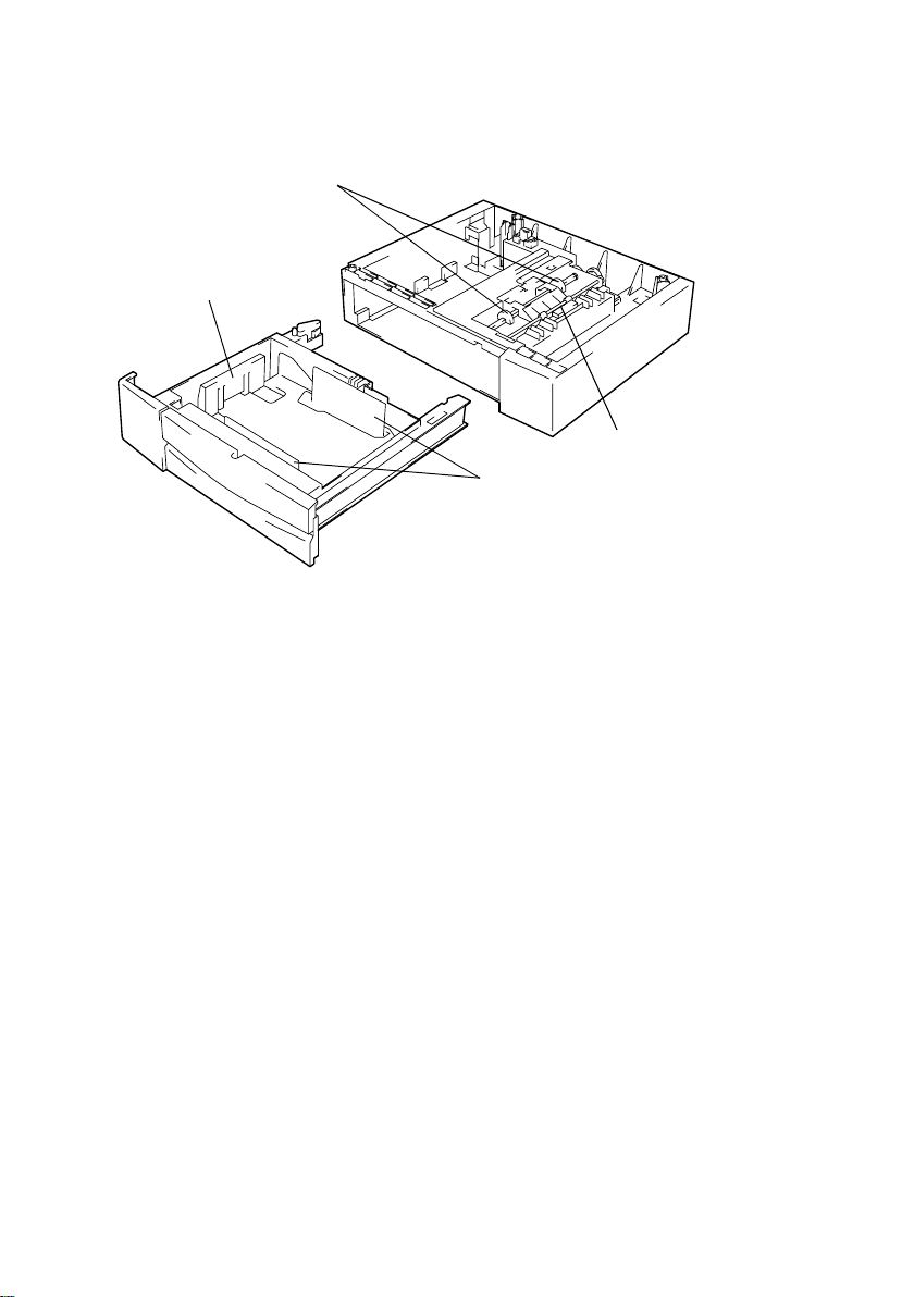
2-2. Tray Positioning
• The tray is positioned with respect to the unit housing at the following two places.
• The positioning rib on the tray that mates with the rib receiving part on the unit housing.
• The boss on the bottom in the rear of the tray that mates with the boss receiving part on
the unit housing. This point serves also as the fulcrum for inclination adjustment.
Boss Receiving Part
Positioning Rib
M-3
Rib Receiving Part
Boss
4646M003AB
Page 8

2-3. Paper Lifting Plate
• The Paper Lifting Plate is pushed upward by the Paper Lifting Springs.
Paper Lifting Plate
Paper Lifting Springs
4646M004AA
2-4. Tray-in-Position Dete ction
• When the tray is slid into the unit housing, the actuator is pushed, allowing the copier to
detect that the tray is in position.
Actuator (Tray Set Sensor S4)
4646M005AA
Control Signal Blocked Unblocked
S4 CN15-5B L H
M-4
Page 9

2-5. Paper Empty Detection
• A paper-empty condition in the Paper Feed Unit is detected by the Paper Empty Sensor.
Paper Empty Sensor PC11
4646M006AA
<Control>
Control Signal Blocked Unblocked
PC11 CN15-5A L H
2-6. Paper Separating Mechanism
• The Paper Take-Up Rolls and Paper Separator Fingers form a loop in the top sheet of
paper, allowing only the top sheet of paper to ride over the fingers and be fed out of the
tray at one time.
Paper Take-Up Roll
Paper Lifting Plate
Paper
Separator Finger
Paper Lifting Spring
4646M007AA
M-5
Page 10

2-7. Paper Take-Up Rolls
• Drive for the paper take-up motion is supplied from the copier through gears and the
Paper Take-Up Solenoid.
• Paper is wedged in the mechanism when the tray is slid out of the unit housing if the
Paper Take-Up Rolls are round in shape. So the rolls are semicircular and the circular
parts of the rolls are positioned on top at times other than take-up.
Paper Take-Up Rolls
Paper Take-Up Solenoid SL5
Transport Roller
4646M008AB
<Control>
Control Signal ON OFF
SL5 CN15-6A L H
2-8. Paper Take-Up Retry Control
To minimize the occurrence of a paper misfeed, the paper take-up sequence is temporarily
halted if the paper fails to reach the Paper Take-Up Sensor within a given period of time
after the sequence has been started. The paper take-up sequence is then performed
again. These paper take-up sequence are repeated a given number of times.
No. of Paper Take-Up Retry Sequences
Paper Take-Up Retry 1
M-6
Page 11

3. WIRING DIAGRAM
CN15-6A(FEED2)
CN15-5A(P_EMP2 ON)
CN15-4A(GND)
CN15-3A(ANODE(P_EMP2))
CN15-2A(GND)
CN15-1A(GND)
CN15-7A(DC24V)
the copier
From
CN15-6B(GND)
CN15-5B(CASET SET2)
1
2
3
PC11
PJ1
1
2
M-7
2
1
SL5
CN2
2
PJ2
1
S4
4646C01TAA
Page 12

DIS/REASSEMBLY,
ADJUSTMENT
Page 13

1. DISASSEMBLY
1-1. Removal of Paper Take-Up Rolls Assy and Paper Take-Up
Rolls
1. Slide out the tray from the unit housing.
2. Pushing the stoppers on both sides of the tray indicated by the arrows, pull the tray out of the unit
housing.
4646D001AA
3. Remove the Paper Take-Up Rolls Assy (one
screw).
4646D002AA
4. Raise the tab and slide the Paper Take-Up Roll in
the direction of the arrow.
4646D003AA
4646D004AB
4646D005AA
5. Remove the Paper Take- Up Roll.
6. When reinstalling the Paper Take-Up Rolls Assy,
make sure that the Paper Take-Up Solenoid is in
the locked position and the circular parts of the
Paper Take-Up Rolls are on the upper side.
D-1
Page 14

1-2. Removal of Paper Take-Up So lenoid
1. Slide out the tray from the unit housing.
2. Pushing the stoppers on both sides of the tray indicated by the arrows, pull the tray out of the unit
housing.
4646D001AA
3. Remove the bracket (two screw).
4646D006AB
4. Unplug one connector.
4646D007AA
4646D008AA
4646D005AA
5. Remove the Paper Take-Up Solenoid (one screw).
6. When reinstalling the Paper Take-Up Solenoid,
make sure that the solenoid is in the locked position and the circular parts of the Paper Take-Up
Rolls are on the upper side.
D-2
Page 15

2. ADJUSTMENT
• Perform the following steps to enter the Tech. Rep. mode and let the copier produce a
test pattern.
<Procedure>
1. Press the following keys in this order :
Clear/Stop → Exposure Control Lighter (<) → Clear/Stop → Exposure Control Darker
(>).
2. Press the 1Key until “F” (Function) appears on the display.
3. Press the Start key to validate the selection of the Function sub-mode.
4. Press the 1Key until “5” (Test Pattern 1) appears on the display.
5. Press the Start key to produce a test pattern.
<Exiting the Mode>
• Press the Clear/Stop key.
NOTE
The test pattern is used when making the following adjustments:
• Inclination adjustment
• Registration adjustments in CD/FD directions
• Follow these steps to enter the Adjust mode.
<Procedure>
1. Press the following keys in this order :
Clear/Stop → Exposure Control Lighter (<) → Clear/Stop → Exposure Control Darker
(>).
2. Press the 1Key as necessary until “A” (Adjust) appears on the display.
3. Press the Start key to validate the selection of the Adjust sub-mode.
<Exiting the Mode>
• Press the Clear/Stop key.
D-3
Page 16

2-1. Inclination Adjustment
1. Select the Paper Feed Unit for the paper source.
2. Produce a test pattern.
4646D009AA
3. Measure dimensions A and B on the test pattern.
A B
4646D011AA
4. Slide out the tray and move the positioning holder
5. Produce a test pattern again to check for correct
4646D012AA
NOTE
After the adjustment has been made, be sure to make
the registration adjustment in the CD/FD directions.
Specifications: A – B = ±1.6 mm
as detailed below.
If the difference is on the plus side, move the
holder to the right.
If the difference is on the minus side, move the
holder to the left.
difference.
D-4
Page 17

2-2. Registration Adjustments in CD/FD Directions
1. Select the Paper Feed Unit for the paper source.
2. Produce a test pattern.
4646D009AA
Registration Adjustment in CD Direction (Ab)
3. Fold the test pattern produced in half and check
C
D
4646D013AA
E
4646D014AA
that the centerline on the test pattern is aligned
with the crease.
If the centerline deviates in the C direction,
decrease the setting value.
If the centerline deviates in the D direction,
increase the setting value.
Registration Adjustment in FD Direction (AC)
4. Measure dimension “E” on the copy.
Specifications: 20 ±2.0 mm
If the dimension is less than the specified range,
increase the setting value.
If the dimension is greater than the specified range,
decrease the setting value.
4646D010AA
4646D015AA
5. Enter the Adjust mode.
6. Press the 1Key until “Ab” or “AC” appears on the
display.
7. Press the Start key to validate the selected function.
8. Using the 1Key or 10Ke y, change the setting value.
9. Press the Start key to validate the setting.
10. Produce a test patter n again to check for correct
adjustments.
D-5
Page 18

MISFEED DETECTION
Page 19

1. MISFEED DETECTION
1-1. Misfeed Detection Sensor Layout
Paper Take-Up Sensor PS1
4007T002AA
1-2. Types of Misfeed Detection and Detection Timing
• The following lists the types of misfeed detection and detection timings for different misfeed locations within the copier.
• The symbols “L” (for the leading edge) and “T” (for the trailing edge) given in ( ) indicate
the particular edge of the paper detected by the sensor.
<Paper Take-Up Misfeed>
Type Detection Start Detection
Paper take-up fail ure detection Paper Take-Up Solenoid
energized
Paper Take-Up Sensor (L)
T-1
 Loading...