

Page 1

DF-313
SERVICE HANDBOOK
Dec. 1999
Ver. 1.0
KONICA CORPORATION
TECHNOLOGY SUPPORT CENTER
TOKYO JAPAN
Page 2

CONTENTS
CONTENTS
SAFETY AND IMPORTANT WARNING ITEM ....................
Refer to the 7075 service handbook on page C-1
1. OUTLINE
DF-313 PRODUCT SPECIFICATIONS................... 1-1
[1] Type ............................................................ 1-1
[2] Functions ....................................................1-1
[3] Machine Data.............................................. 1-1
[4] Maintenance ...............................................1-1
[5] Operating Environment ............................... 1-1
CENTER CROSS-SECTIONAL DRAWING............ 1-2
DRIVE SYSTEM DIAGRAM.................................... 1-3
ORIGINAL CONVEYANCE PROCESS .................. 1-4
[1] Single side original copy mode (large)........ 1-4
[2] Single side original copy mode (small) .......1-6
[3] Double side original copy mode (large) ......1-7
[4] Double side original copy mode (small) ...... 1-8
[5] Mixed original copy mode ........................... 1-9
2. UNIT EXPLANATION
EXTERNAL SECTION ............................................ 2-1
[1] Composition ................................................ 2-1
[2] Mechanism..................................................2-1
ORIGINAL FEED/CONVEYANCE/EXIT
SECTION ................................................................ 2-3
[1] Composition ................................................ 2-3
[2] Mechanisms................................................ 2-3
[3] Original Feed/Conveyance/Scan Control....2-5
[4] Original Reversal and Conveyance
Control ........................................................2-8
[5] Original Exit Control .................................. 2-10
[6] Original Size Detection Control................. 2-12
3. DISASSEMBLY/ASSEMBLY
EXTERNAL SECTION ............................................ 3-1
[1] Removing the RADF ................................... 3-1
[2] Reinstalling the RADF.................................3-2
ORIGINAL FEED/CONVEYANCE/EXIT
SECTION ................................................................ 3-5
[1] Removing/Cleaning/Reinstalling the Original
Feed Roller Unit .......................................... 3-5
[2] Cleaning the Cleaning Pad ......................... 3-5
[3] Replacing the Original Feed Roller/Separa-
tion Roller/Auxiliary Separation Roller ........3-6
[4] Cleaning the Paper Separation Rubber ......3-8
[5] Replacing the Double Feed Prevention
Roller/Torque Limiter ..................................3-8
[6] Cleaning Photo Sensors/Mirrors for Photo
Sensors....................................................... 3-9
Page 3

1
OUTLINE
1 OUTLINE
Page 4
DF-313 PRODUCT SPECIFICATIONS
DF-313
[1] Type
Type:
Sheet-through type reversible DF
[2] Functions
Original size:
A3R, B4R, A4, A4R, B5, B5R, A5, A5R, 11x 17R,
8.5 x11, 8 x13
• All sizes are detected automatically.
• Mixing of original sizes possible.
Original type
Plain original:
50 - 130 g/m2 fine quality paper.
Special original:
Original feed and conveyance ability may be inferior to those of 50 to 130 g/m2 fine quality original.
Only SDF mode single-sided passage allowed
for 131 to 200 g/m2 thick original and bonded
original.
The following types of original cannot be used:
• OHP film
• Blueprint masters
• Label original
• Offset masters
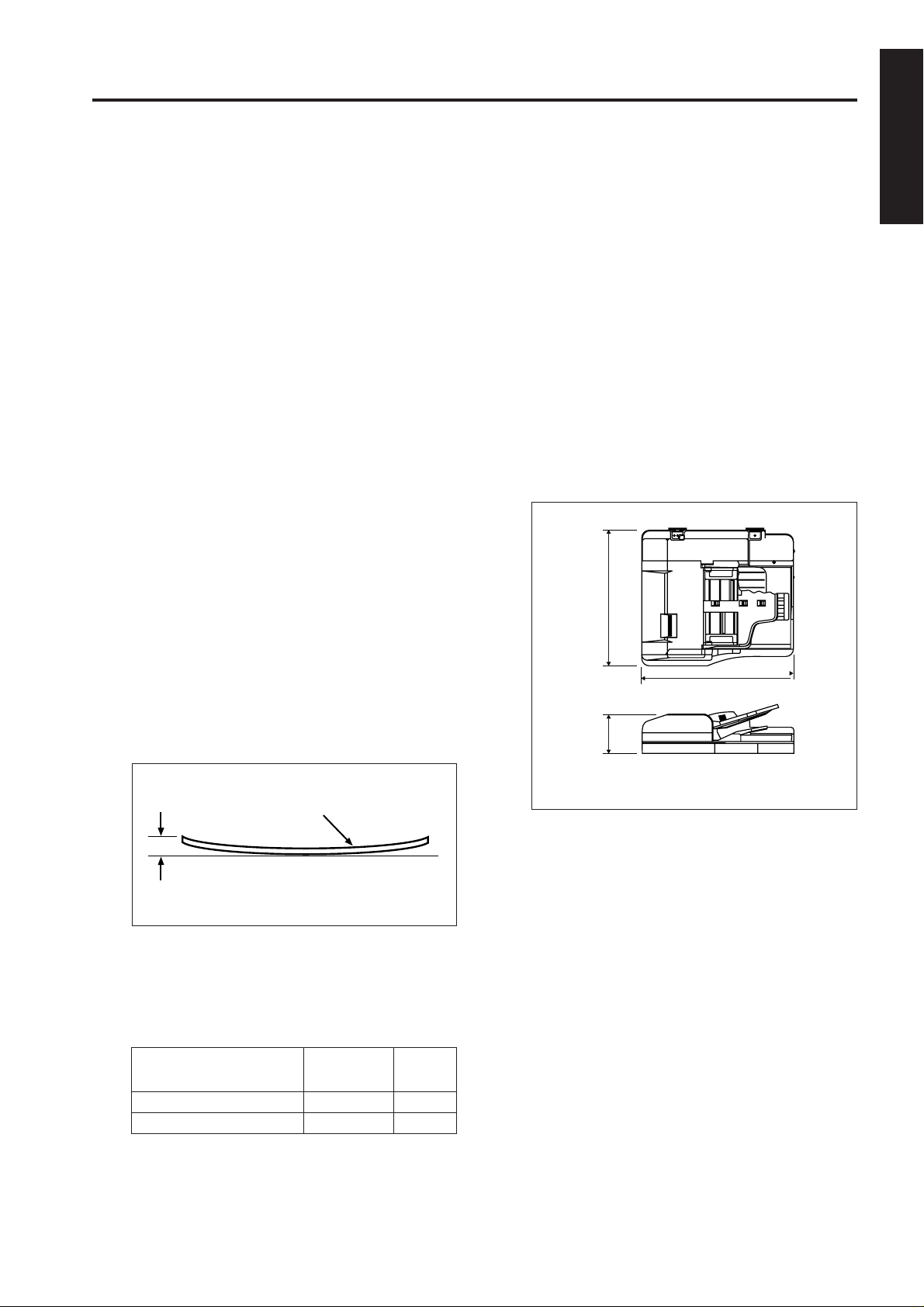
Original curling:
10 mm maximum
Original feed layout:
Face-up placement, centered, U-turn feed/
straight eject (large size/small size independent
eject), reversal section placed at ejection side.
Original image read position:
At the slit glass section
[3] Machine Data
Power source:
24V DC/5V (supplied from the main unit)
Max. power consumption:
Less than 120VA
Weight:
Approx. 20 kg
Machine dimensions:
570
650
170
1 OUTLINE
unit:mm
Original
Curling
Maximum number of stacked originals:
100 sheet maximum (80g/m2)
Original read speed (copies per minute)
Mode Original Feed
size speed
Single-sided original A4 75
Dual-sided original A4 50
[4] Maintenance
Maintenance:
Same as the main unit
[5] Operating Environment
Temperature:
10°C to 30°C (50°F to 86°F)
Humidity:
10% to 80%RH
Note: The contents of this manual may change
without prior notice.
1 - 1
Page 5
DF-313
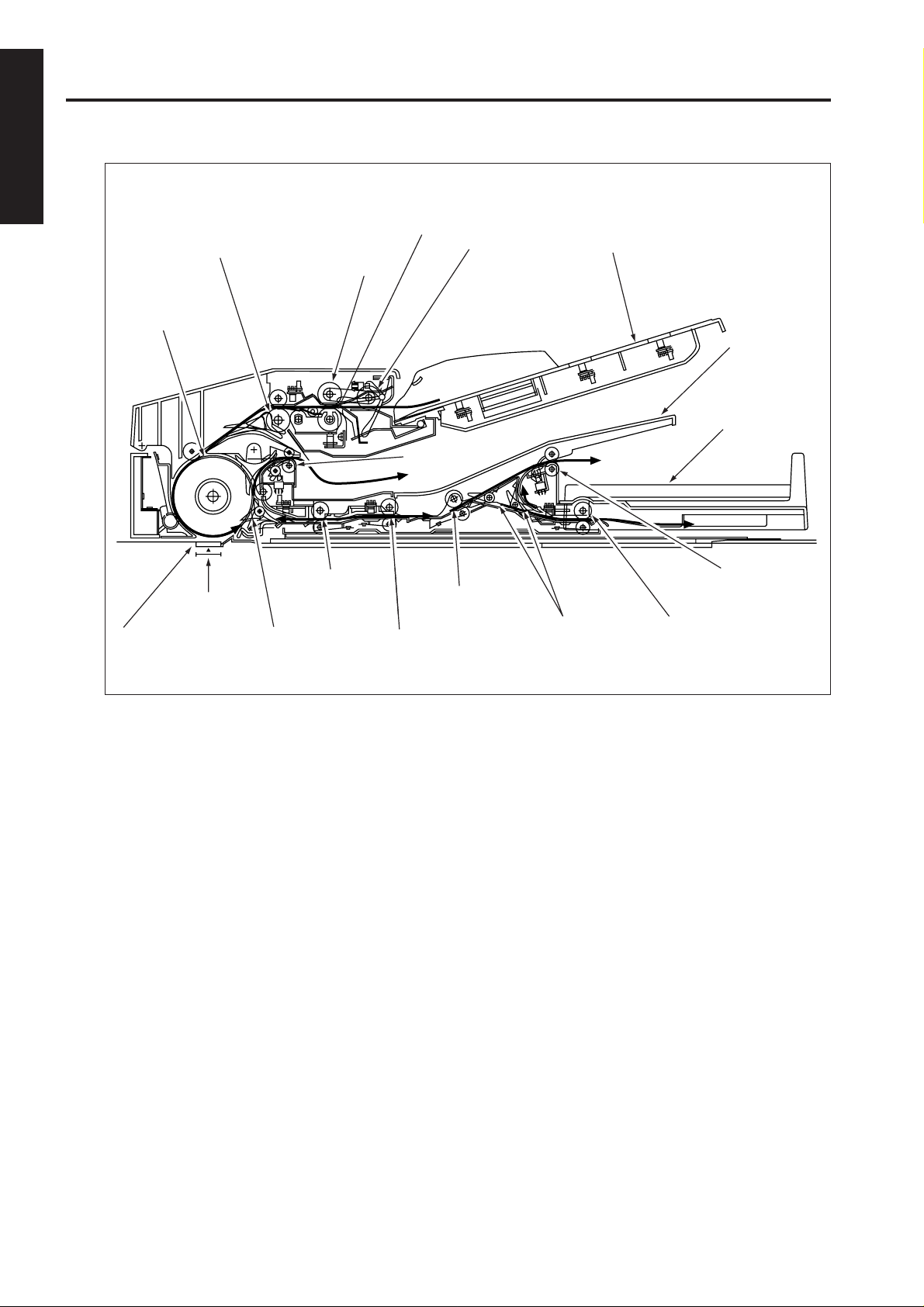
CENTER CROSS-SECTIONAL DRAWING
1 OUTLINE
Double feed
Registration roller
Original
conveyance
roller
prevention roller
Separation roller
Original feed roller Original feed tray
Original exit
roller 1
Original exit
tray (for largesize original)
Original exit
section (for smallsize original)
Slit glass
Read position
Flapper
Reversal roller
Reversal
conveyance roller 1
Reversal conveyance roller 2
Original exit gate
Original exit
roller 2
Original exit reversal
roller
1 - 2
Page 6
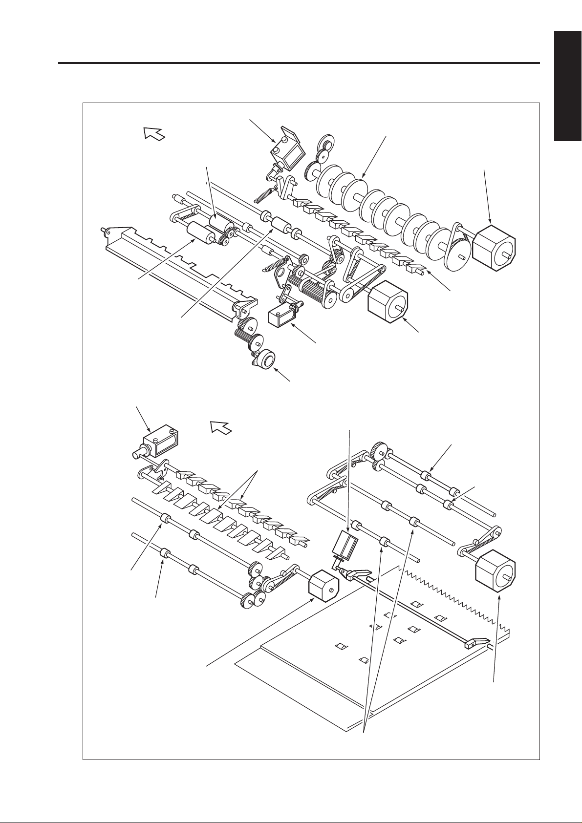
DRIVE SYSTEM DIAGRAM
DF-313
FRONT
Original
feed roller
Registration roller
Original exit gate SD
(SD303)
Flapper drive
SD (SD 301)
Separation roller
Original conveyance roller
SDF switching SD
(SD304)
Tray up/down drive
motor (M303)
1 OUTLINE
Original conveyance motor
(M301)
Flapper
Original feed motor
(M302)
Original exit
roller 2
Original exit motor 2
(M305)
Original exit reversal
roller
Pressure roller release SD (SD302)
FRONT
Original exit gate
Original exit roller 1
Reversal roller
Original exit motor 1
(M304)
1 - 3
Reversal conveyance roller
Page 7
DF-313
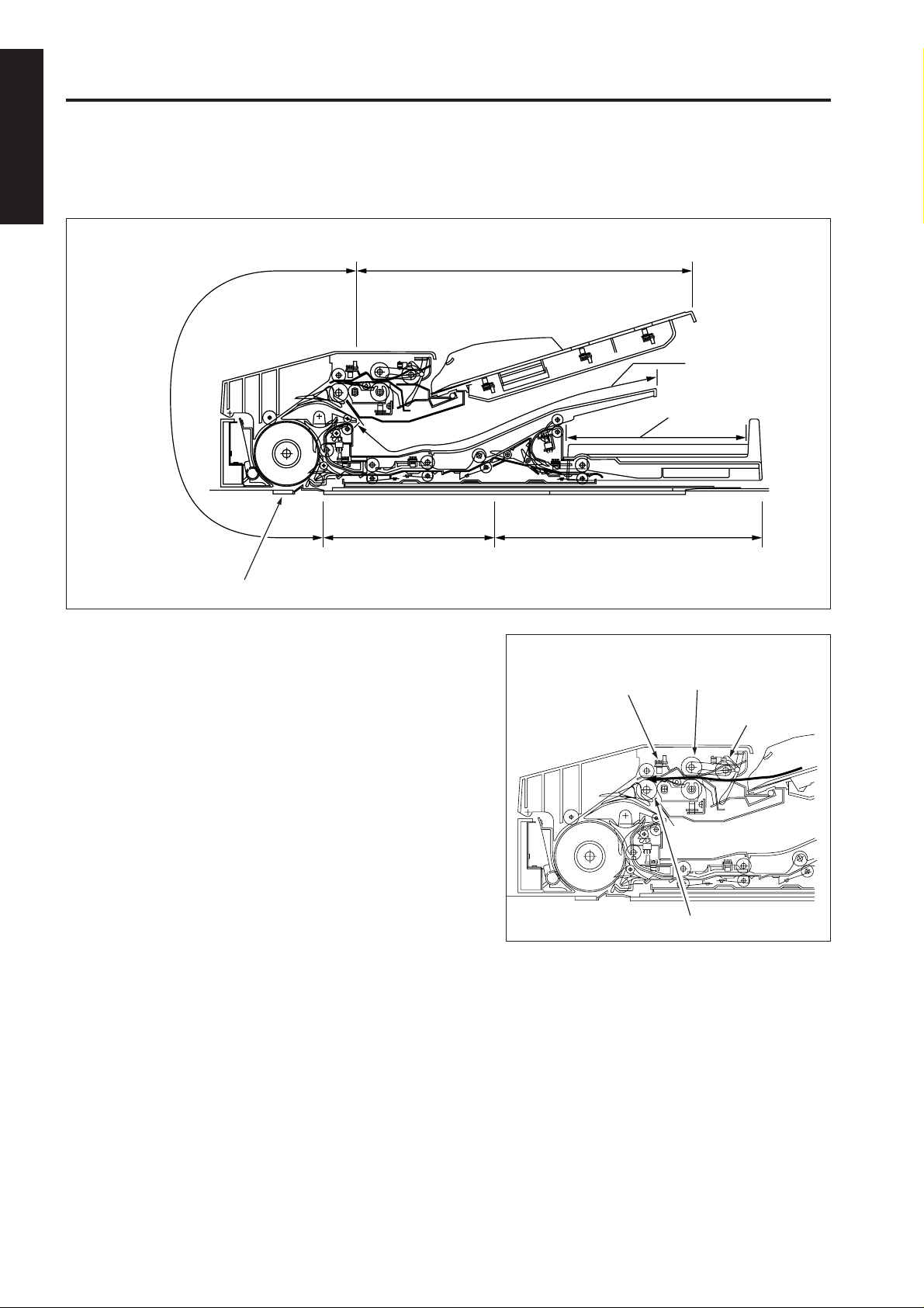
ORIGINAL CONVEYANCE PROCESS
1 OUTLINE
The DF-313 consists of a original feed section, conveyance section, reversal section, original exit reversal section,
original exit tray (large), and original exit tray (small).
Original conveyance
section
Original reversal
section
Slit glass (Read section)
The original placed faced up on the original feed tray
is fed from the topmost original. The f ed original is not
conveyed to the original glass. Instead, it is read when
it passes the slit glass placed in the conveyance path.
Original feed section
PS306
(Original
registration detection)
Original exit tray
Original exit tray (small)
Original exit reversal
section
Separation roller
Original feed
roller
The DF-313 operation consists of (a) single side original
copy mode, (b) double side original copy mode, (c)
mixed original copy mode and Z fold mode. Each has
a different conveyance path. The conveyance path
also depends on the original size.
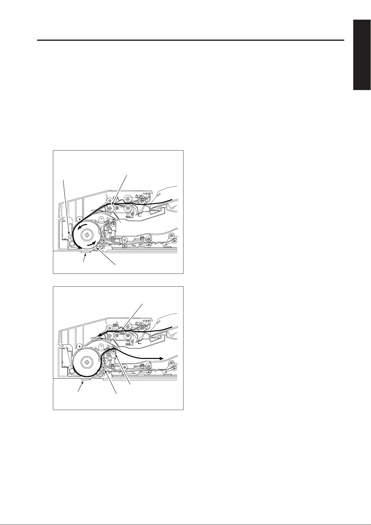
[1] Single side original copy mode
(large)
(single side to single side copy, single side to
double side copy)
The original set in the original feed tray is fed by
the original feed roller and separation roller until
PS306 (original registration detection) turns on.
Registration roller
1 - 4
Page 8
DF-313
When PS306 turns on, the registration roller prefeeds the original and original is rapidly conveyed
to the conveyance roller. The speed of the
conveyance roller changes to scan speed at
predefined interval after PS306 turns ON and
feeds the original over the slit glass.
At this point, if the next original is present, it is
pre-fed as soon as PS306 detects its leading
edge.
PS308
(Original conveyance
detection)
Registration roller
1 OUTLINE
Slit glass
Slit glass
Original conveyance roller
Next original
Original exit roller 1
Flapper
The original is read when it passes over the slit
glass. The original that has been read is
conveyed along the circumference of the
conveyance roller by the opening of the flapper,
goes through original exit roller 1, and is exited
to the original exit tray (large).
1 - 5
Page 9
DF-313
1 OUTLINE
[2] Single side original copy mode (small)
(single side to single side copy, single side to double side copy)
The original feed and conveyance actions up to scanning are performed in the same manner as for single
side original copy mode (large). The original that has been scanned is fed to the original re versal unit b y the
reversal roller because the flapper is closed and the paper exit path is blocked. The original fed to the
reversal unit passes through the original exit roller 2 and is exited to the original exit tray (small) since the
original exit gate is closed.
Flapper
Reversal roller
Original reversal
section
Original exit gate
Original exit roller 2
1 - 6
Page 10
DF-313
[3] Double side original copy mode (large)
(double side to single side copy, double side to double side copy)
The original conveyance action up to the start of scanning of the front side of the first double side original is
the same as for single side original copy mode (large). The original that has been scanned and read on the
front side is fed by the reversal roller to the reversal unit since the flapper is closed and the original exit path
is blocked. The original f ed to the re versal unit does not fit in the re v ersal unit so the original e xit gate opens
to feed it to the original exit reversal section.
1 OUTLINE
Flapper
Reversal roller
Original exit gate
When PS309 (original reversal detection) detects the
trailing edge of the original and turns off, the reversal
roller changes direction and feeds the original in the
reversal section to the conveyance roller. Since the
original is passed over the surface of the flapper , it is
sent to the conveyance roller with sides reversed.
The original reaching the conveyance roller does not
exit the reversal roller so the pressure roller is
released. The conveyance roller feeds this original
over the slit glass for scanning.
PS309
(Original reversal
detection)
Reversal roller
Original exit reversal roller
The original that has completed scanning of the
back side is fed inside the re versal unit once again
since the flapper is closed. When PS309 detects
the trailing edge of the original and turns off, the
reversal roller changes direction and feeds the
original in the reversal unit to the conveyance
roller. Since the flapper is now opened, the
original is fed along the flapper, passes through
original exit roller 1, and is exited to the original
exit tray (large).
Reversal roller
Flapper
Pressure roller
1 - 7
Flapper
Original exit roller 1
Page 11
DF-313
1 OUTLINE
[4] Double side original copy mode (small)
(double side to single side copy, double side to double side copy)
The original conveyance action up to the start of scanning of the back side is the same as double side
original copy mode (large). The original that has been scanned and read on the back side is fed by the
reversal roller to the reversal section since the flapper is closed and the original exit path is blocked. Then
the original exit gate opens and the original is fed to the original exit reversal section.
PS313
(Original exit reverse detection)
Reversal roller
Original exit gate
Original exit reversal roller
1 - 8
Page 12
DF-313
When PS313 (original exit reverse detection) detects the trailing edge of the original and turns off, the
original exit reversal roller changes direction and feeds the original to the original exit gate. Since the
original exit gate is closed, the original passes over the original exit gate and is exited from the original exit
roller 2 to the original exit section (small) with sides reversed.
PS313
(Original exit reverse detection)
Original exit roller 2
1 OUTLINE
Original exit gate
Original exit reversal roller
[5] Mixed original copy mode
The mixed original copy mode supports both the same series originals and different series originals. Ho wever ,
since the size of the original in the conveyance direction is determined by the ON interval of PS306, size
detection is performed prior to scanning.
The subsequent operations are the same as other copy modes.
For details on size detection, refer to section [6] Original Size Detection Control in section 2. UNIT EXPLANATION.
1 - 9
Page 13

2
UNIT EXPLANATION
2 UNIT EXPLANATION
Page 14

EXTERNAL SECTION
[1] Composition
Jam access
cover
Original exit tray (for large-size original)
DF-313
Original feed tray
2 UNIT EXPLANATION
Original exit section
(for small-size original)
[2] Mechanism
Mechanism
*1
Jam removal
Jam access cov er
Jammed original release knob
Original conveyance guide open/
close lever
Platen guide
*1 Jam removal
If an original jam occurs during original feed, open
the Jam access cover and the original conveyance
guide by releasing the original conveyance guide
open/close lever, then turn the jammed original
release knob to remove the jammed original.
Jammed original
release knob
System
Jam access cover
Original conveyance
guide open/close lever
If an original jam occurs during original reversal
operation, open the platen guide to remove the
jammed original .
Lock
Platen guide
Original conveyance
guide open/close lever
Original conveyance
guide
2 - 1
Page 15

DF-313
If an original jam occurs during original exit, open
the original feed tray and original exit tray (for
large-size original) to remove the jammed
original.
2 UNIT EXPLANATION
Original feed
tray
Original exit tray
(for large-size original)
2 - 2
Page 16

ORIGINAL FEED/CONVEYANCE/EXIT SECTION
[1] Composition
SD303
(Original exit gate SD)
Original feed tray
Jam access cover
DF-313
SD301
(Flapper drive SD)
SD302
(Pressure roller release SD)
M305
(Original exit 2)
M304
(Original exit 1)
[2] Mechanisms
Mechanism System
Original feed Original feed roller
Double feed Double feed prevention
prevention roller
Separation roller
Original conveyance
*1 Original conveyance Flapper
path selection
*2 Original reverse and Reversal roller pressure
feed Reversal roller rotation
*3 Original exit Gate 1
path selection Gate 2
Original conveyance roller
M301
(Original conveyance)
M302
(Original feed)
SD304
(SDF switching SD)
*1 Original conveyance path selection
In the two-sided copy mode, the original
conveyance path selected after completion of
scanning differs depending on whether the image
on the front surface is to be printed or the image
on the back surface is to be printed. A flapper is
used to switch between these original
convey ance paths. The SD301 (flapper driv e SD)
is turned ON/OFF to switch between the reversal
section and the original exit section.
2 UNIT EXPLANATION
FRONT
SD301
(Flapper drive SD)
Flapper
2 - 3
Page 17

DF-313
*2 Reversed original feed
In the double-side copy mode, the original fed to
the reversal section is fed back by pressing the
the pressure roller against the reversal roller.
The pressure roller is driven by the SD302
(pressure roller release SD).
SD302
(Pressure roller release SD)
2 UNIT EXPLANATION
FRONT
Pressure roller
*3 Original exit path swtching
Large-size one-side and two-side originals are
exited to the original exit tray (for large-size
original). On the other hand, small-size one-side
and two-side originals are exited to the original
exit section (for small-size original) through the
reversal section. The small-size two-side original
fed to the reversal section is reversed and exited
to the small size original exit section. The original
exit path switching to which the original is exited
is performed by the gate 1 and gate 2, driven by
the ON/OFF contol of the SD303 (original exit
gate SD).
SD303
(Original exit gate SD)
FRONT
Original exit gate
2 - 4
Page 18

[3] Original Feed/Conveyance/Scan Control
PS312 PS311 PS308 PS301 PS316 PS315 PS305 PS306
DF-313
MS301
5VDC
PS312
PS312 LED CONT
5VDC
SGND
PGND
24VDC
MAIN BODY
PS311
PS311 LED CONT
DF VALID
DF CTS
DF DTR
5VDC
DF RXD
DF RTS
DF TXD
DF DSR
5VDC
PS308
PS308 LED CONT
SD304
SGND
PS301
24VDC
SD304 DRIVE
5VDC
PGND
FM301 LD
FM301 M302 M301 M303
Original feed is performed by the original feed roller and
separation roller driven by M302 (original feed). Original
conveyance is performed by the original conveyance roller
driven by M301 (original conveyance).
M301 and M302 are controlled by DFCB (RADF control board).
1. Operation
a. Sensor activation at power ON
When SW1 (main) is ON, a sensitivity adjustment
for PS306 (original registration detection), PS308
(original conveyance detection), PS311 (original
skew detection 1) and PS312 (original skew detection 2) are performed. However, automatic
adjustment is not performed when the RADF jam
access cover is opened and MS301 (cover open/
close MS) is OFF or when there is original inside
the RADF.
b. Pressing original against roller
(1) First original
When a control signal is received from the main
body, M303 (tray up/down drive) turns forward
to raise the original feed tray. By this moment,
5VDC
SGND
PS316
DFCB
FM301 DRIVE
5VDC
M302 DRIVE B
M302 DRIVE B
M302 DRIVE A
M302 DRIVE A
SGND
PS315
24VDC
24VDC
5VDC
PS305
24VDC
24VDC
SGND
M301 DRIVE A
M301 DRIVE A
M301 DRIVE B
M301 DRIVE B
the original is raised and pressed against the
original feed roller.
After PS315 (tray upper limit detection) turns ON,
M303 stops after a predefined interval and leaves
the original feed tray raised in standby state.
After M302 feeds the first original, M303 rotates
backward after a predefined time has elapsed
since it stopped, lowering the original feed tray,
and the pressure on the originals is released.
M303 continues to rotate backward for a
predefined interval and then stops and remains
in standby state. At this point the original feed
tray waits without lowering to the bottom.
(2) Second and subsequent originals
When PS308 (original conveyance detection)
detects the leading edge of the first original and
turns ON, M303 that was in standby turns forward
to raise the original feed tray and presses the
original against the original feed roller.
Subsequent operations are the same as for the
first original.
5VDC
PS306
PS306 LED CONT
M303 DRIVE B
M303 DRIVE B
M303 DRIVE A
M303 DRIVE A
MS301
24VDC
24VDC
24VDC
2 UNIT EXPLANATION
2 - 5
Page 19

DF-313
c. Original feed
M302 drives the original feed roller and separation roller.
When a control signal from the main unit is received, M302 rotates forward at low speed, stops,
and goes into standby.
When the original feed tray is raised and PS315
turns ON, M302 turns backward after a predefined
interval to start original feed operation. Then,
when PS306 (original registration detection)
detects the leading edge of the original and turns
ON, M302 switches to high speed forward after a
2 UNIT EXPLANATION
predefined interval to complete the original feed
operation. After completing original feed at high
speed forward, M302 returns to low speed forward
and stops and goes into standby when PS308
(original conveyance detection) turns ON.
d. Original conveyance operation
When feeding the first original, M302 transports
the original to the conveyance roller by continuing
to rotate at high and low speed.
During this time, M301 (original conveyance)
starts rotating forward at low speed at predefined
time after PS306 turns ON. The original reached
to the conveyance roller is then conveyed to the
scan position.
After starting conveyance of the first original,
M301 continues to rotate forward at low speed
until the last original is scanned.
e. Scan operation
The original is passed over the slit glass of the
optics unit by the low speed forward rotation of
M301 and read (scanned). While the original is
being scanned, original feed and conveyance operations continue, triggered by the turning ON of
PS308.
f. Original mis-centering detection control
PS311 (original skew detection 1) and PS312
(original skew detection 2) are provided to detect the inclined leading edge of the original during conveyance.
PS311 and PS312 are placed at the front and
back of the pre-scan conveyance path and determine the inclination of the original by
measuring the difference in interval at which the
leading edge of the original turns these switches
ON. A skewed image caused by original
inclination is corrected through image processing
so that the image on the original is copied to a
copy paper as it is on the original.
g. SDF (Single Document Feeder) control
When SDF mode is selected, SD304 (SDF
switching SD) cut the drive force to the double
feed prevention roller to facilitate original feeding.
(1) ON timing
At the start of original feed
(2) OFF timing
When PS306 turns OFF
h. FM301 (ADF fan) operation
FM301 is used to cool M301 so that M301 does
not overheat during operation.
(1) ON timing
At the start of original feed
(2) OFF timing
When original ejection completed.
i. Jammed original ejection control
Upon receiving a control signal from the main
body, M301 rotates at high speed forward,
attempting to eject a jammed original in the
RADF.
2. Signals
a. Input signal
(1) MS301 (MS301 to DFCB)
Jam access cover open/close detection signal.
[L] : Cover opened
[H]: Cover closed
(2) PS301 (PS301 to DFCB)
RADF open/close detection signal.
[L] : RADF closed
[H]: RADF opened
(3) PS305 (PS305 to DFCB)
No original on original feed tray detection signal.
[L] : Original present
[H]: No original
(4) PS306 (PS306 to DFCB)
Original feed over original conveyance roller
detection signal.
[L] : Original present
[H]: No original
(5) PS308 (PS308 to DFCB)
Pre-scan position original detection signal.
[L] : Original present
[H]: No original
2 - 6
Page 20

DF-313
(6) PS311 (PS311 to DFCB)
Front side original skew detection signal.
[L] : Original present
[H]: No original
(7) PS312 (PS312 to DFCB)
Rear side original skew detection signal.
[L] : Original present
[H]: No original
(8) PS315 (PS315 to DFCB)
Original feed tray upper limit detection signal.
[L] : Tray at upper limit
[H]: Tray not at upper limit
(9) PS316 (PS316 to DFCB)
Original feed tray lower limit detection signal.
[L] : Tray at lower limit
[H]: Tray not at lower limit
(10)FM301 LD (FM301 to DFCB)
Goes [L] when FM301 reaches predefined speed.
(11)DF TXD (MAIN BODY to DFCB)
Serial data for transmitting main body PRCB
operating status to RADF.
(12)DF RTS (MAIN BODY to DFCB)
Send the Request To Send signal from main body
PRCB to RADF.
(13)DF DSR (MAIN BODY to DFCB)
Send the Data Set Ready signal from main body
PRCB to RADF.
b. Output signals
(1) PS306 LED CONT (DFCB to PS306)
Reflective sensor PS306 LED ON/OFF control
signal.
[L] : PS306 LED ON
[H]: PS306 LED OFF
(2) PS308 LED CONT (DFCB to PS308)
Reflective sensor PS308 LED ON/OFF control
signal.
[L] : PS308 LED ON
[H]: PS308 LED OFF
(3) PS311 LED CONT (DFCB to PS311)
Reflective sensor PS311 LED ON/OFF control
signal.
[L] : PS311 LED ON
[H]: PS311 LED OFF
(4) PS312 LED CONT (DFCB to PS312)
Reflective sensor PS312 LED ON/OFF control
signal.
[L] : PS312 LED ON
[H]: PS312 LED OFF
(5) M301 DRIVE A, A (DFCB to M301)
M301 A phase drive signal.
(6) M301 DRIVE B, B (DFCB to M301)
M301 B phase drive signal.
(7) M302 DRIVE A, A (DFCB to M302)
M302 A phase drive signal.
(8) M302 DRIVE B, B (DFCB to M302)
M302 B phase drive signal.
(9) M303 DRIVE A, A (DFCB to M303)
M303 A phase drive signal.
(10)M303 DRIVE B, B (DFCB to M303)
M303 B phase drive signal.
(11)FM301 DRIVE (DFCB to FM301)
FM301 ON/OFF drive signal.
[L] : FM301 ON
[H]: FM301 OFF
(12)DF TXD (DFCB to MAIN BODY)
Serial data for transmitting RADF operating status to main body PRCB.
(13)DF DTR (DFCB to MAIN BODY)
Send the Data Terminal Ready signal from RADF
to main
(14) DF CTS (DFCB to MAIN BODY)
Send the Clear To Send signal from RADF to main
body
(15)DF VALID (DFCB to MAIN BODY)
Image forming start signal.
body
PRCB.
PRCB.
2 UNIT EXPLANATION
2 - 7
Page 21

DF-313
[4] Original Reversal and Conveyance Control
PS308 PS309 PS304 PS306
2 UNIT EXPLANATION
5VDC
SGND
24VDC
5VDC
PS308
PS308 LED CONT
DF VALID
DF CTS
PGND
MAIN BODY
PS309
PS309 LED CONT
DF DTR
DF RXD
DF RTS
DF DSR
5VDC
PS304 LED CONT
DF TXD
In two side copy mode, an original that has been
scanned on the front side is conveyed to the original
reversal section to be reversed and then rescanned.
At entrance to the original reversal section, there is a
flapper to switch the original conveyance path. The
flapper is driven by SD301 (flapper drive SD). The
reversal roller, which reverses and con v eys front-sidescanned original to the original reversal section and
feeds that original to the scan section again, is driven
by M304 (original exit 1). The original reversal roller
which conveys original to the original reversal section
is driven by M305 (original exit 2). When reversing
and feeding large originals, the pressure roller is released by SD302 (pressure roller release SD).
M304, M305, SD301, and SD302 are controlled by
DFCB (RADF control board).
1. Operation
a. Sensor activation during power ON
When SW1 (main) is turned ON, a sensitivity
adjustment for PS309 (original reversal detection)
and PS313 (original exit reverse detection) are
performed. However, automatic adjustment is
not performed when the RADF jam access cover
5VDC
PS304
PS313
5VDC
PS306
PS306 LED CONT
24VDC
SD301 DRIVE
SD301 SD302 SD303
DFCB
5VDC
PS313
24VDC
SD302 DRIVE
PS313 LED CONT
24VDC
is opened and MS301 (cover open/close MS) is
OFF or when there is original inside the RADF.
b. Original conveyance path switching/
reversal and original feed operation
(1) Small size original
SD301 is always OFF and the flapper is closed.
Therefore, the scanned original, whether it is
single side or double side, is conveyed to the
reversal section by M304 rotating at low speed
forward.
When copying the back side of a double-side
original, at predefined interval after PS309
(original reversal detection) detects the trailing
edge of original and turns OFF, M304 rotates
backward at low speed and then at high speed
to reverse and feed the original. The reversed
original is conveyed through the flapper and the
guides to the conveyance roller.
(2) Large size original
The scanned-single side original is conveyed to
the original exit tray (large) by the original
conveyance roller since SD301 is ON and the
flapper is opened.
M305 DRIVE A
M305 DRIVE B
M305 DRIVE B
SD303 DRIVE
M304M305
24VDC
24VDC
M305 DRIVE A
M302 DRIVE B
M304 DRIVE B
M304 DRIVE B
M302 DRIVE B
M302 DRIVE A
M302 DRIVE A
24VDC
24VDC
M302 M301
24VDC
24VDC
M304 DRIVE A
M304 DRIVE A
24VDC
24VDC
M301 DRIVE A
M301 DRIVE A
M301 DRIVE B
M301 DRIVE B
2 - 8
Page 22

DF-313
In the case of large double-side original, the original is conveyed to the reversal section when
SD301 turns OFF after scanning the front side
of a double-side original . The original reaching
the reversal section does not fit in the reversal
section so it is fed to the large-size original exit
tray side by the large original reversal roller,
which is driven by M305 (original exit 2). During
this time, SD303 (original exit gate SD) turns ON
and the original exit gate is closed.
The original conveyed to the reversal section is
reversed and fed to the scan section again in the
same manner as small originals. Since the
original reaching the conveyance roller does not
exit the reversal roller, SD302 is turned ON at
predefined interval after high speed backward
rotation of M304 to release the pressure roller
for the reversal roller. This enables original
convey ance using the conve yance roller . SD302
turns OFF when it detects an image scan
complete signal from the main unit.
c. Two side original next original feed
operation
(1) Small size original
During front-side scanning of two-side original,
the original feed of the next one is started by the
rotation of M302 (original feed) when PS306
(original registration detection) detects the trailing edge of the previous original and turns OFF.
The next original stops and waits in standby at
predefined interval after the turning ON of PS306
by its own leading edge.
When the back side of the first original is scanned
and PS308 (original conveyance detection) turns
ON, M302 turns ON after a predefined interval
to resume original feed to scan the front side of
the next original. Thereafter, the same operation is repeated.
(2) Large size original
During front-side scanning of double-side original, the original feed of the next original is started
when PS306 (original registration detection) detects the trailing edge of the previous original and
turns OFF. The next original stops and waits in
standby at predefined interval after the turning
ON of PS306 by its own leading edge.
During ejection of previous original by reverse
and exit operation, when PS309 (original reversal
detection) detects the trailing edge of the previous original and turns OFF , M302 turns ON after
a predefined interval to resume original feeding
to scan the front side of the next original. Thereafter, the same operation is repeated.
Note: See [5] Original Exit Control for informa-
tion on reverse and exit operation.
d. Jammed original ejction control
Upon receiving a control signal from the main
unit, M304 and M305 rotate at high speed
forward, attempting to eject a jammed original in
the RADF.
2 UNIT EXPLANATION
2. Signals
a. Input signals
(1) PS304 (PS304 to DFCB)
Reversal section original detection signal.
[L] : Original present
[H]: No original
(2) PS309 (PS309 to DFCB)
Reversal section entrance original detection
signal.
[L] : Original present
[H]: No original
(3) PS313 (PS313 to DFCB)
Original ejection reversal section original detection signal.
[L] : Original present
[H]: No original
b. Output signals
(1) M304 DRIVE A, A (DFCB to M304)
M304 A phase drive signal.
(2) M304 DRIVE B, B (DFCB to M304)
M304 B phase drive signal.
(3) M305 DRIVE A, A (DFCB to M305)
M305 A phase drive signal.
(4) M305 DRIVE B, B (DFCB to M305)
M305 B phase drive signal.
2 - 9
Page 23

DF-313
[5] Original Exit Control
PS307 PS309 PS304
5VDC
SGND
PS307
2 UNIT EXPLANATION
5VDC
SGND
PGND
24VDC
MAIN BODY
The ejection destination of the original that has
been scanned depends on the size of original.
The original exit roller 1 which conveys the
original to the original exit tray (large) is driven
by M304 (original exit 1). The original exit roller
2 which conveys the original to the original exit
section (small) is driven by M305 (original exit
2). The flapper which switches the original exit
path and the original exit gate are driven by
SD301 (flapper drive SD) and SD303 (original
exit gate SD) respectively.
M304, M305, SD301, and SD303 are controlled
by DFCB (RADF control board).
1. Operation
a. Small size original exit operation
(1) Single-side original
Scanned original is conveyed to the reversal section since SD301 is OFF and the flapper is closed.
Original conveyed to the reversal section is
conveyed to the original exit gate by the reversal
roller which is driven by M304. During this time,
M304 drives the conveyance roller with low speed
forward rotation.
5VDC
PS309
PS309 LED CONT
DF VALID
DF CTS
DF DTR
DF RXD
DF RTS
DF DSR
5VDC
PS304
PS304 LED CONT
DF TXD
PS314 PS313
5VDC
SGND
PS314
DFCB
5VDC
PS313
PS313 LED CONT
24VDC
SD301 DRIVE
SD301 SD302 SD303
The original is conveyed to the original exit roller
2 since SD303 is OFF and the original exit gate
is opened. M305 drives the original exit roller 2
with low speed forward rotation and ejects the
original to the original exit section (small) with
the original surface facing down.
(2) Two-side original
A original that has been scanned on the back
side is conveyed to the original exit gate in the
same manner as single-side original. During this
time, SD303 is ON and the original exit gate is
closed. Theref ore, the original is passed through
the original exit rev ersal roller , which is driven by
the low speed forward rotation of M305, and
conveyed to the original exit reversal section.
M305 turns OFF when PS313 ( original exit reverse detection) is turned OFF by the conveyed
original. When SD303 turns OFF and the original exit gate opens, M305 starts high speed backward rotation after a predefined interval and reverses the direction of the conveyed original.
Since the original exit gate is opened, the original is conveyed to the original exit section (small)
rather than returning to the reversal section.
24VDC
SD302 DRIVE
M305 M304
24VDC
24VDC
M305 DRIVE A
M305 DRIVE A
M305 DRIVE B
M305 DRIVE B
24VDC
SD303 DRIVE
24VDC
24VDC
M301
24VDC
M304 DRIVE A
M304 DRIVE A
M304 DRIVE B
M304 DRIVE B
M301 DRIVE A
M301 DRIVE A
M301 DRIVE B
M301 DRIVE B
24VDC
2 - 10
Page 24

As a result, the two-side original is ejected with
the front side facing down.
b. Large size original ejection operation
(1) Single-side original
The scanned original is conveyed to the original
exit roller 1 by the conveyance roller since SD301
is ON and the flapper is opened. The original
exit roller 1 is driven by the low speed forward
rotation of M304 and the original is ejected to
the original exit tray (large) with the copy surface
facing down.
(2) Two-side original
The original that has been scanned on the back
side is conveyed to the reversal section since
SD301 is OFF and the flapper is closed.
When PS309 (original reversal detection) detects
the trailing edge of conveyed original, SD301
(flapper drive SD) is turned ON and the flapper
is opened. Then, M304 (original exit 1) rotates
backward and the original is ejected to the original exit tray (large size original) since the flapper
is open.
DF-313
2 UNIT EXPLANATION
2. Signals
a. Input signal
(1) PS307 (PS307 to DFCB)
Original exit tray (large) entrance original
detection signal.
[L] : Original present
[H]: No original
(2) PS314 (PS314 to DFCB)
Original exit section (small) entrance original
detection signal.
[L] : Original present
[H]: No original
2 - 11
Page 25

DF-313
[6] Original Size Detection Control
PS317 PS308 PS306
5VDC
SGND
PS317
2 UNIT EXPLANATION
5VDC
SGND
PGND
24VDC
MAIN BODY
The size of the original placed in the original feed
tray is detected by PS302 (original size detection
1), PS303 (original size detection 2), and VR301
(original size detection).
PS302, PS303, and VR301 are controlled by
DFCB (RADF control board) through PTBD (tray
drive board). DFCB contains a non-volatile
memory for storing data such as timing data and
original size detection threshold.
1. Operation
a. Normal copy mode
DFCB detects the original size from the combination of the following signals:
(1) Drum axis direction size detection
A guide plate is connected to VR301 and the resistance vary with the position of the guide plate.
This is used to determined the vertical dimension of the original.
(2) Original feed direction size detection
The horizontal dimension of the original is detected with the ON/OFF combination of PS302
and PS303.
PS315
DF VALID
DF CTS
5VDC
PS308
PS308 LED CONT
DF DTR
DF RXD
DF RTS
DF TXD
DF DSR
5VDC
PS306
PS306 LED CONT
24VDC
24VDC
PS302 PS303 VR301
M301 DRIVE A
M301
M301 DRIVE A
M301 DRIVE B
M301 DRIVE B
5VDC
SGND
PS302
PTBD
DFCB
5VDC
5VDC
SGND
PS303
PS302
PS303
SGND
VR301
5VDC
SGND
VR301
b. Mixed copy mode original size detection
Size detection during mixed copy mode is performed as follows:
(1) Drum axis direction size detection
The vertical dimension of the largest original is
determined by the position of the guide plate.
(2) The ON interval of PS306 (original registration
detection) after the original passes the registration roller is used to determine the horizontal
dimension of each original.
2 - 12
Page 26

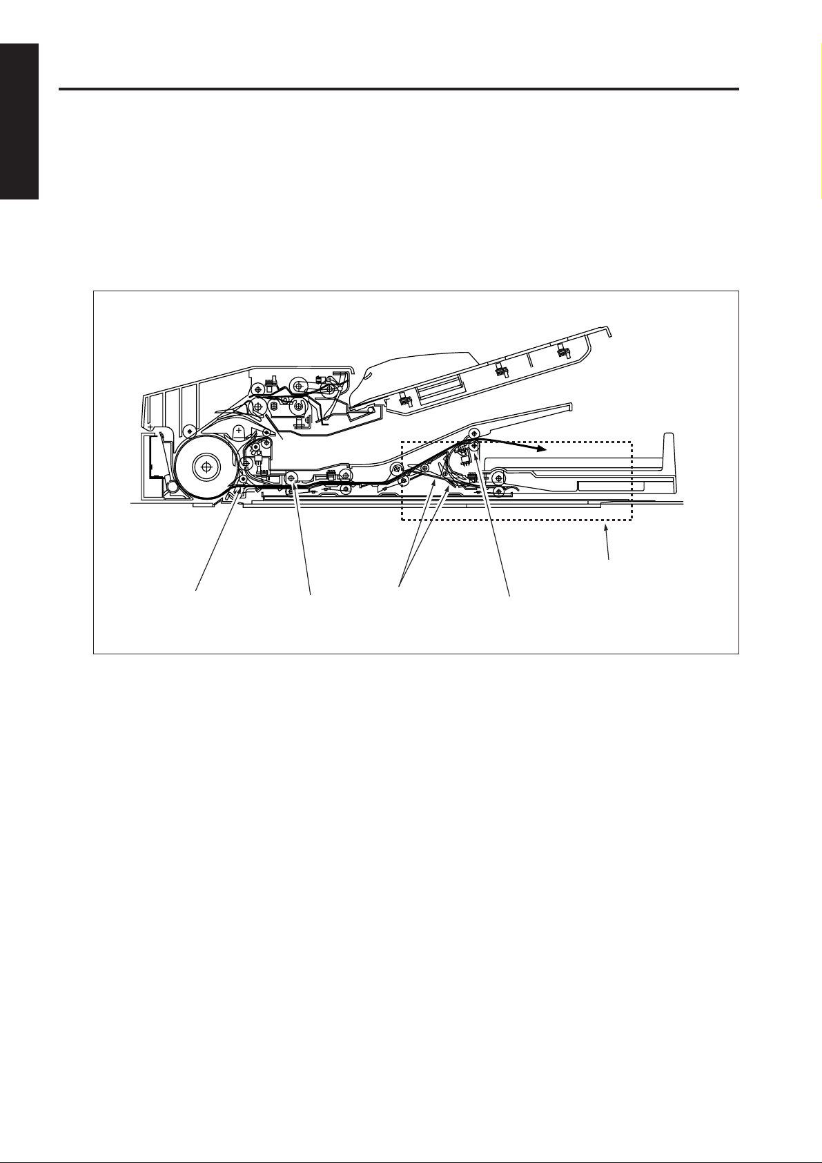
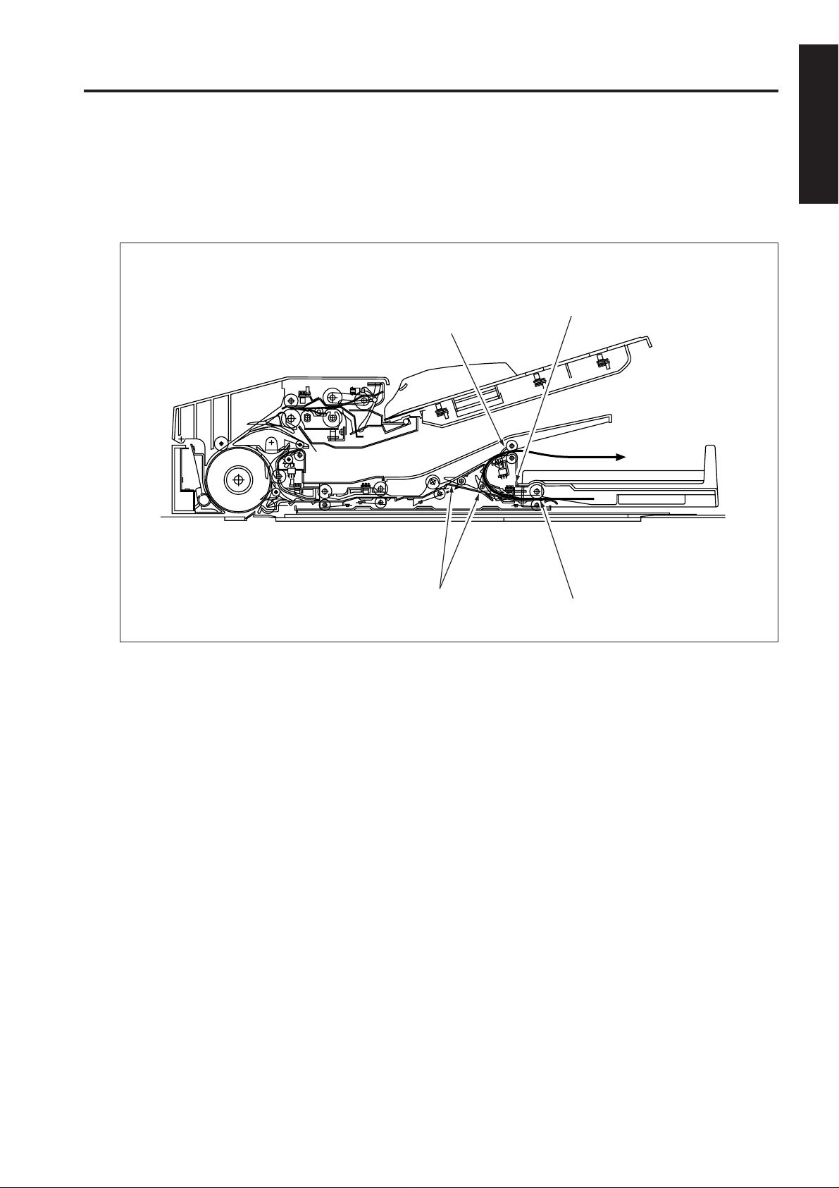
DF-313
(3) Original feed direction size detection
When the original is fed, M301 (original
conveyance) turns forward and conveys the
original to the original exit tray (large). M301
continues to rotate forward until PS306 detects
the trailing edge of the original and turns OFF.
At this point, the ON interval of PS306 is used to
detect the size of original in the feed direction.
PS 306 (Original
Registration
roller
PS 308 (Original conveyance detection)
registration detection)
Original
conveyance roller
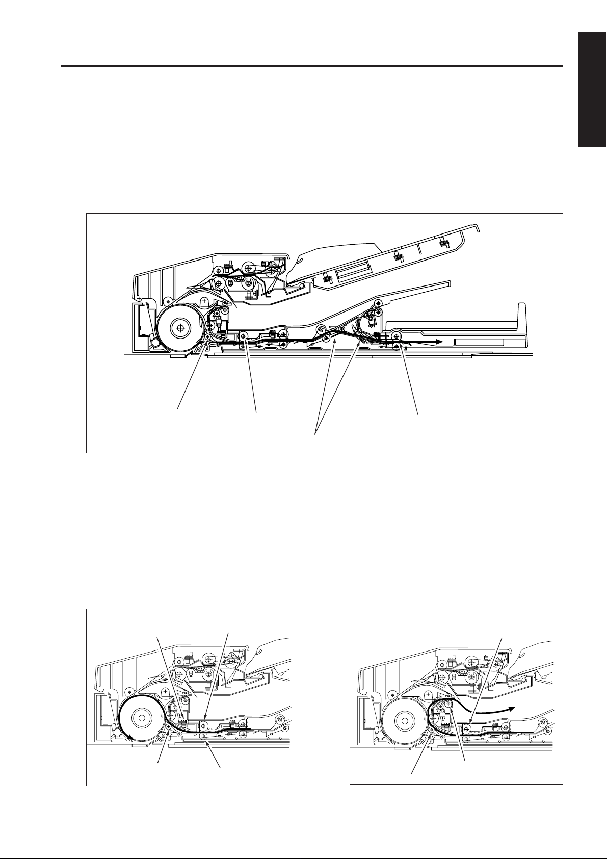
After a predefined interval since PS306 turns
OFF, M301 changes direction and returns the
leading edge of the original conveyed to the
original exit section to the scan wait position. The
trailing edge of the returned original is conveyed
to the original exit tray (large) due to the shape
of the conveyance guide plate.
The backward rotation of M301 stops at
predefined interval after PS308 (original conveyance detection) detects the leading edge of the
original and turns OFF.
Scan stanby position
Thereafter, read operation (scan) is performed
in the same manner as normal mode.
Second original
First original
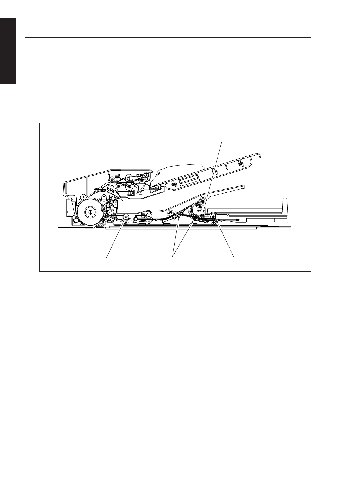
The size detection of the second and subsequent
originals differ for single-side mode and two-side
mode.
• Single-side mode: After scanning of the pre vious original starts
• Two-side mode: When scanning of the back
side of the previous original starts
c. Allowed size combination
(❏: Same siz e, ❍ : Same series, ▲: Diff erent series, ✕: Mixing prohibited, —: Not supported)
Reference original (maximum-size original
detectable with guide plate)
A3 A4 B4 B5 A4R A5
A3 ❏❍——————
A4 ❍❏——————
B4 ▲▲❏❍————
B5 ▲▲❍❏————
A4R ▲▲▲▲❏❍——
A5 ▲▲▲▲❍❏——
B5R ✕✕▲▲▲▲❏ —
B6R ✕✕✕✕✕✕▲❏
2 UNIT EXPLANATION
B5R B6R
Original conveyance roller
PS 308 (Original conveyance detection)
2 - 13
Page 27

DF-313
2. Signals
a. Input signals
(1) PS302 (PS302 to PTBD to DFCB)
Original horizontal dimension detection signal
[L] : Original present
[H]: No original
(2) PS303 (PS303 to PTBD to DFCB)
Original horizontal dimension detection signal
[L] : Original present
[H]: No original
(3) VR301 (VR301 to PTBD to DFCB)
2 UNIT EXPLANATION
Original vertical dimension detection signal
(4) PS317 (PS317 to DFCB to MAIN BODY)
Original size detection timing signal during platen
mode
Original size is detected when this signal changes
from [H] to [L].
2 - 14
Page 28

3
DISASSEMBLY/ASSEMBLY
3 DIS./ASSEMBLY
Page 29

3 DIS./ASSEMBLY
This section explains how to disassemble and reassemble the machine.
When disassembling and reassembling the machine, follow the
precautions given below.
1. Be sure the power cord has been unplugged from the wall outlet.
2. The disassembled parts must be reassembled following the
disassembly procedure in reverse unless otherwise specified.
3. Care should be taken not to lose small parts. Care should also be
taken not to install small parts in wrong places.
4. Do not operate the machine before installing all the disassembled
parts completely .
5. Removal of some screws is prohibited in this section. Never loosen
them.
Page 30

EXTERNAL SECTION
DF-313
[1] Removing the RADF
Caution: Make sure the power cord of the
main unit has been unplugged
from the wall outlet.
a. Procedure
(1) Remove the rear cover.
(2) Remove the two screws to detach the two stop-
pers.
Screws
Stopper
(5) Remove the screw to disconnect the ground
cable.
(6) Remove the two relay connectors (CN31, CN32).
Ground
cable
Screw
Relay connector (CN32)
Relay connector (CN31)
(7) Remove the three screws to detach the cable
conduit.
3 DIS./ASSEMBLY
(3) Open the RADF to the upright position.
(4) Remove the three screws to detach the top cover
(rear) of the main unit.
Screws
Top cover (rear)
Cable conduit
Screws
3 - 1
Page 31

DF-313
(8) Draw the cable to the top of the main unit.
(9) Close the RADF. Remove the two screws to
detach each of the two fixing plates (R).
Screws
Fixing plate (R)
(10)Open the RADF up to the upright position.
3 DIS./ASSEMBLY
(11)Holding the RADF, remove one screw to detach
each of two fixing plates.
(12)Holding the RADF, remove it from the main unit.
Caution: When the fixing plates (F) are
removed, the RADF may fall down to
the rear side. Be sure to hold the
RADF while performing steps 11 and
12.
[2] Reinstalling the RADF
Caution: Make sure the power cord of the
main unit has been unplugged
from the wall outlet.
a. Procedure
(1) Place the RADF on the top of the main unit and
loosely secure each of the two fixing plates (F)
with one screw.
Caution: The nec ked hole in the fixing plate (F)
must fit over the guide screw.
(2) Remove the two screws to detach the original
stopper plate (left).
Guide
screw
Screw (Tighten
temporarily)
Screws
Original
stopper plate
(left)
Necked
hole
Fixing
plate (F)
Fixing plate (F)
Screw
(3) Following the removal procedure in reverse, in-
stall the cable conduit, two relay connectors
(CN31, CN32), ground cable, and top cover (rear)
of the main unit.
(4) Install two RADF positioning jigs in the mounting
holes of the original stopper plate (left).
3 - 2
Page 32

DF-313
(5) Close the RADF to mate the reference holes and
RADF positioning jigs.
Reference hole
(round hole)
Reference hole
(oblong hole)
RADF positioning
jigs
(6) Install two screws to secure each of the two fixing
plates (R) following the removal procedure in
reverse.
(7) Open the RADF, install the other screw for each
of the two fixing plates (F), and finaly tighten all
the four screws to secure the two fixing plates (F).
(8) Remove the RADF positioning jigs and install the
original stopper plate (left) with two screws.
(9) Close the RADF and check whether both stopper
pieces on the RADF-side touch the slit glass.
Caution: The state of contact between the
stopper pieces and the silt glass can
be checked by looking into the slits in
the top cover of the main unit.
Stopper
piece
Stopper
piece
Slit glass
Top cover
(middle)
3 DIS./ASSEMBLY
Slit
Slit
3 - 3
Page 33

DF-313
(10)If both stopper pieces do not touch the slit glass
at the same time, make adjustments using adjusting screws A and B alternately.
Adjusting screw B
Adjusting screw A
(11)Perform steps 9 and 10 repeatedly until the two
3 DIS./ASSEMBLY
stopper pieces touch the slit glass at the same
time.
(12)Install the rear cover of the main unit.
3 - 4
Page 34

ORIGINAL FEED/CONVEYANCE/EXIT SECTION
DF-313
[1] Removing/Cleaning/Reinstalling the
Original Feed Roller Unit
Caution: Make sure the power cord of the
main unit has been unplugged
from the wall outlet.
a. Procedure
(1) Open the Jam access cover.
(2) Remove the screw to detach the sensor cover.
Screw
Jam access cover
(3) Remove the spring.
(4) Remove the two stop rings to slide the bearing
and one-way clutch outward.
(5) Slide the original feed roller unit to the front to
release it from the coupling, then remove it upward.
Sensor cover
(6) Clean rollers using a blower brush or the like.
(7) Reinstall the original feed roller unit in the reverse
order of the removal procedure.
Caution: Make sure the angled portion of the
original feed roller unit is positioned
above the angled portion of the stay.
If the angled portion of the original
feed roller unit is positioned below the
angled portion of the stay , originals are
not fed properly.
[2] Cleaning the Cleaning Pad
Caution: Make sure the power cord of the
main unit has been unplugged
from the wall outlet.
a. Procedure
(1) Open the movable cover.
(2) Remove one screw to detach the cleaning pad.
(3) Using a blower brush, clean the cleaning pad.
Screw
Cleaning
pad
Movable
cover
3 DIS./ASSEMBLY
Original feed
roller unit
Bearing
Stop ring
One-way clutch
Stop ring
Spring
Original feed
tray
Angled portion
Coupling
Angled portion
of original feed
roller unit
Stay
Angled
portion of
stay
Resistration
roller
(4) Reinstall the above parts following the removal
steps in reverse.
3 - 5
Page 35

DF-313
[3] Replacing the Original Feed Roller/
Separation Roller/Auxiliary
Separation Roller
Caution: Make sure the power cord of the
main unit has been unplugged
from the wall outlet.
a. Procedure
(1) Remove the original feed roller unit.
(2) Remove the one-way clutch.
(3) Remove stop ring (1) to detach gear (1) and belt.
(4) Remove stop ring (2) and pull out shaft (1) to
detach the original feed roller.
(5) Pull the pin for gear (1) and the spacer from shaft
(2).
(6) Remove stop rings (3), (4), and (5) to pull the pin
for gear (2) from shaft (2).
(7) Pull out shaft (2) to detach the separation roller.
(8) Remove stop ring (6) to pull the pin for gear (3)
from shaft (3).
3 DIS./ASSEMBLY
3 - 6
Page 36

(9) Pull out shaft (3) to detach the auxiliary separation roller.
DF-313
Original feed roller
Auxiliary separation roller
Stop ring (3)
Belt
Gear (3) (with a pin)
Shaft (1)
Stop ring (2)
Stop ring (6)
Shaft (3)
3 DIS./ASSEMBLY
Shaft (2)
Stop ring (5)
Gear (2) (with a pin)
One-way clutch
Stop ring (1)
Gear (1) (with a pin)
Spacer
Stop ring (4)
Separation roller
(10)Reinstall the original feed roller/separation roller/auxiliary separation roller in the reverse order of the removal
procedure.
Caution: Make sure the one-way clutch and rollers are oriented properly when reinstalling them.
3 - 7
Page 37

DF-313
[4] Cleaning the Paper Separation
Rubber
Caution: Make sure the power cord of the
main unit has been unplugged
from the wall outlet.
a Procedure
(1) Remove the original feed roller unit.
(2) Clean the paper separation rubber using a drum
cleaner and cleaning pad.
3 DIS./ASSEMBLY
Paper
separation
rubber
[5] Replacing the Double Feed
Prevention Roller/Torque Limiter
Caution: Make sure the power cord of the
main unit has been unplugged
from the wall outlet.
a. Procedure
(1) Remove the original feed roller unit.
(2) Remove the two screws to detach the auxiliary
roller assembly.
Screw
Auxiliary roller assembly
(3) Reinstall the cleaning roller in the reverse order of
the removal procedure.
(3) Remove the stop ring to detach the gear.
(4) Slide the two bearings outward to detach the
double feed prevention roller unit.
Double feed
prevention unit
Bearing
Bearing
Stop ring
Gear
3 - 8
Page 38

DF-313
(5) Remove the stop ring to detach the double feed
prevention roller and torque limiter.
(6) Reinstall the double feed prevention roller and
torque limiter in the reverse order of the removal
procedure.
Caution: Make sure the double feed prevention
roller is oriented properly when
reinstalling it.
Double feed prevention roller
Torque limiter
Stop ring
[6] Cleaning Photo Sensors/Mirrors for
Photo Sensors
a. Procedure
(1) Close the RADF.
(2) Clean sensors using a blower brush or the like.
PS310 (original count detection)
PS303 (original size
detection 2)
PS302 (original size detection 1)
3 DIS./ASSEMBLY
(3) Open the RADF.
(4) Remove the two screws to detach the driven
roller assembly.
(5) Remove the two screws to detach the original
conveyance guide.
Original
conveyance
guide
Screws
Driven roller assembly
Screws
3 - 9
 Loading...