

Page 1

3
DISASSEMBLY/ASSEMBLY
3 DIS./ASSEMBLY
Page 2

3 DIS./ASSEMBLY
This section explains how to disassemble and reassemble the machine.
When disassembling and reassembling the machine, follow the
precautions given below.
1. Be sure the power cord has been unplugged from the wall outlet.
2. The disassembled parts must be reassembled following the
disassembly procedure in reverse unless otherwise specified.
3. Care should be taken not to lose small parts. Care should also be
taken not to install small parts in wrong places.
4. Do not operate the machine before installing all the disassembled
parts completely .
5. Removal of some screws is prohibited in this section. Never loosen
them.
Page 3

EXTERNAL SECTION
EXTERNAL SECTION
[1] Replacing Ozone Filters
Caution: Be sure the power cord has
been unplugged from the wall
outlet.
Caution: When replacing ozone filters, insert
them in the openings in the main body
as far as they will go.
a. Procedure
(1) Loosen the two screws to remove the cooling fan
cover.
(2) Replace two ozone filters 1 (upper/2) and one
ozone filter 2 (lower/1).
Ozone filter 1
Screws
(loosen 2)
[2] Removing and Reinstalling the
External Cover
Caution: Be sure the power cord has
been unplugged from the wall
outlet.
a. Procedure
(1) Remove the two screws to detach the option
cover.
(2) Remove the nine screws to detach the rear cover.
Rear cover 1
Screws (9)
3 DIS./ASSEMBLY
Ozone filter 2
(3) Reinstall the above parts following the removal
steps in reverse.
Cooling cover
Option cover 1
(3) Remove the six screws to detach the left side
cover.
Screws (6)
Left side cover
Screws (2)
3 - A - 1
Page 4

EXTERNAL SECTION
(4) Remove the four screws to detach the right side
cover (upper).
Right side cover (upper)
Screws (4)
(5) Open the vertical paper transport jam access
door.
(6) Remove the four screws to detach the right side
3 DIS./ASSEMBLY
cover (lower).
[3] Removing and Reinstalling the Front
Right Door
Caution: Be sure the power cord has
been unplugged from the wall
outlet.
a. Procedure
(1) Open the front right door.
(2) Remove the screw to disconnect the ground
cable.
Ground
cable
Right side cover (lower)
Screws (4)
Vertical paper
transport access
door
(7) Reinstall the above parts following the removal
steps in reverse.
Caution: Covers can be detached separately.
Screw
(3) Loosen the two screws securing the hinge.
(4) While holding the top of the front right door by
hand so that it does not fall down, remove the
door with the hinge pin held up.
Front
right door
Screws
(loosen)
3 - A - 2
(5) Reinstall the above parts following the re-
moval steps in reverse.
Page 5

EXTERNAL SECTION
[4] Removing and Reinstalling the Front
Left Door
Caution: Be sure the power cord has
been unplugged from the wall
outlet.
a. Procedure
(1) Open the front left door.
(2) Remove the screw to disconnect the ground
cable.
Ground cable
[5] Removing and Reinstalling the
Operation Panel
Caution: Be sure the power cord has
been unplugged from the wall
outlet.
a. Procedure
(1) Open the RADF.
(2) Remove the two shoulder screws to remove
the original stopper plate (right).
(3) Remove the three shoulder screws to remove
the original stopper plate (rear).
(4) Remove the two shoulder screws to remove
the original stopper plate (left).
(5) Remove the platen glass.
Shoulder
screws
(2)
Shoulder
screws (3)
Original
stopper
plate (rear)
Shoulder
screws (2)
3 DIS./ASSEMBLY
Screw
(3) Loosen the two screws securing the hinge.
Caution: When loosening the screws, hold the
top of the door by hand so that it does
not fall down.
(4) Remove the door with the hinge pin held up.
Front left door
Screws
(loosen)
Original
stopper
plate (left)
Platen glass
Original
stopper plate
(right)
(5) Reinstall the above parts following the removal
steps in reverse.
3 - A - 3
Page 6

EXTERNAL SECTION
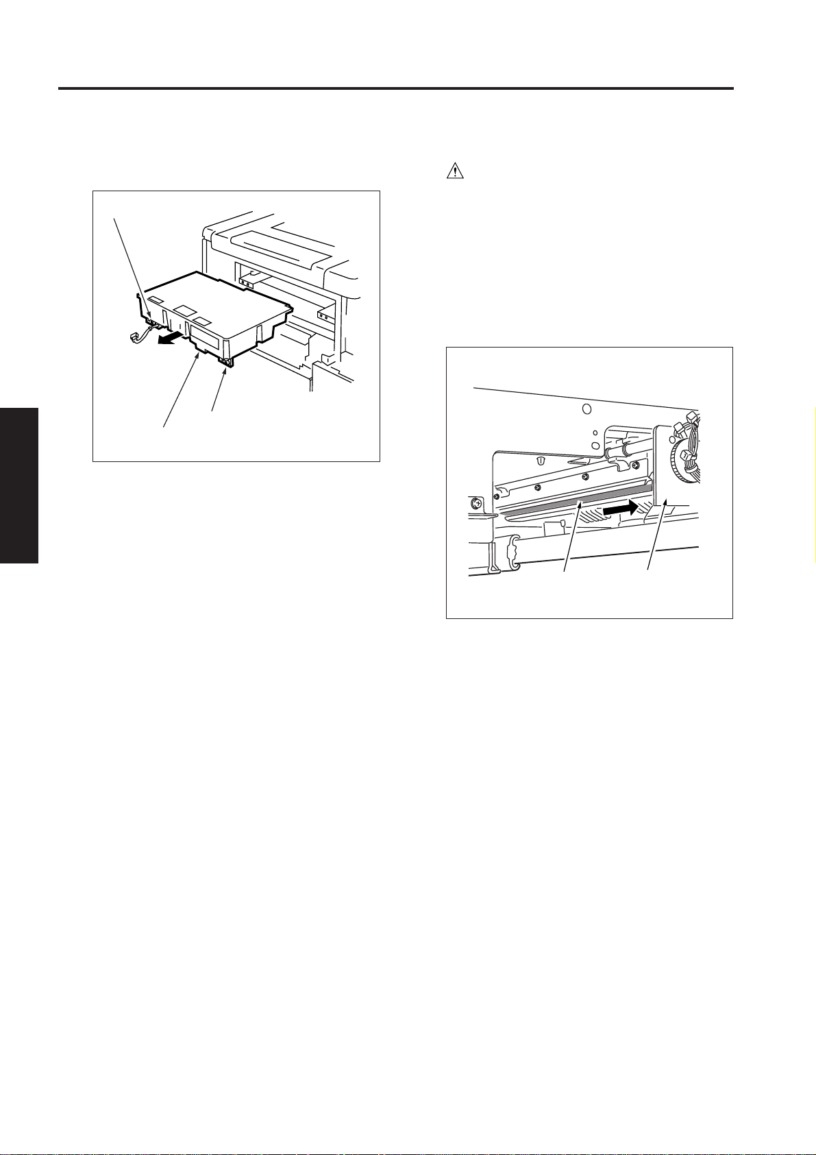
(6) Remove the six screws to detach the top
cover (middle).
(7) Open the front right door and the front left door.
Screws (6)
Top cover (middle)
(8) Draw out the toner supply unit. (See “TONER
3 DIS./ASSEMBLY
SUPPLY UNIT.”)
(9) Remove the seven screws (three at the top and
four on the bottom).
(10)Draw out the operation panel forward.
Caution: When removing the operation panel,
pay attention to the following points:
• The operation panel and main
body are connected with a wiring
harness. Moving the operation
panel too far away from the main
body could break the wiring
harness.
• Care should be taken not to
damage the display section.
(11) Disconnect the two relay connectors (CN475,
CN157) and remove the operation panel.
Connector (CN475)
Connector (CN157)
Screws (3 at the top)
Screws (4 on the buttom)
(12)Reinstall the above parts following the removal
steps in reverse.
3 - A - 4
Page 7
DRIVE SECTION
DRIVE SECTION
[1] Removing and Reinstalling the
Drum Motor
Caution: Be sure the power cord has
been unplugged from the wall
outlet.
Caution: Be sure to draw the drum unit out of
the main body before removing or
reinstalling the drum drive motor.
If you fail to draw out the drum unit,
the cleaning blade may be damaged
because the drum rotates when
installing or removing the flywheel
or gear.
a. Procedure
(1) Draw the drum unit out of the main body. (See
“DRUM UNIT.”)
(2) Remove the rear cover. (See “EXTERNAL SEC-
TION.”)
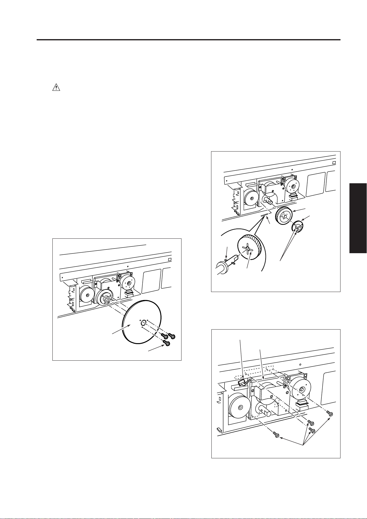
(3) Remove the three screws to remove the three
flywheels.
(4) Loose the two setscrews to remove the gear
holder, gear, and pin from the shaft.
Caution 1: Install the gear with the shaft pin fit
into the groove at the back of the
gear. As the pin inserted in the shaft
moves freely, take care not to drop
or lose it.
Caution 2: Secure the gear holder with the
setscrews while pressing the gear
holder against the gear.
Gear
Gear
holder
Pin
Pin
3 DIS./ASSEMBLY
Flywheels (3)
Setscrews (loosen 2)
Groove (at
the back of
gear)
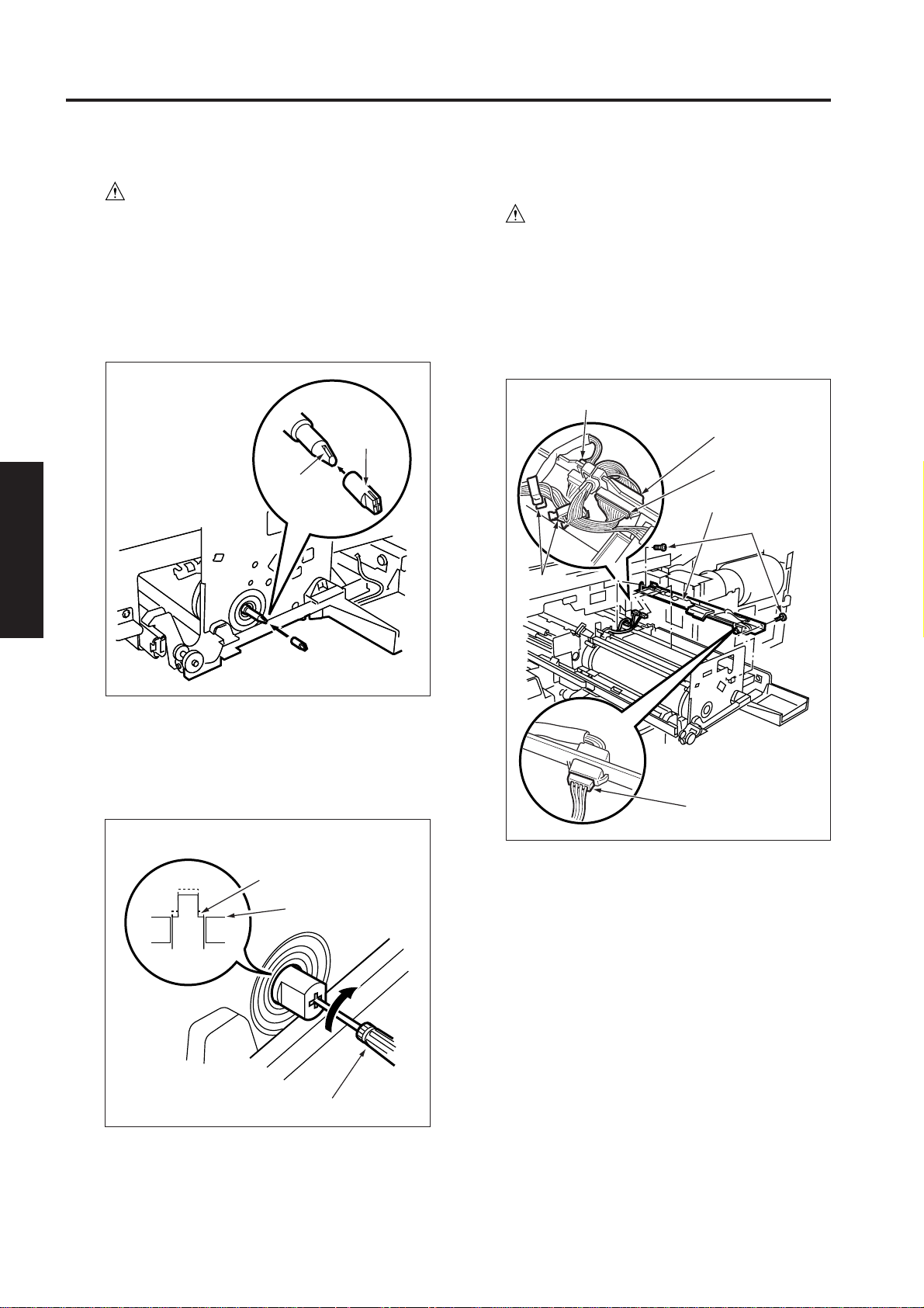
(5) Disconnect the connector (CN58) and remove
the four screws to detach the drum motor unit.
Connector (CN58)
Drum motor unit
Screws (3)
3 - B - 1
Screws (4)
Page 8

DRIVE SECTION
(6) Disconnect the connector (CN180) and remove
the four screws and two locking supports to
remove the drum motor from the drum motor unit.
Screw (4)
Drum motor
(M2)
Connector (CN180)
Locking supports
(7) Reinstall the above parts following the removal
3 DIS./ASSEMBLY
steps in reverse.
Caution: When installing the gear holder, set it
to fit to the gear, then secure it b y the
set screw .
[2] Removing and Reinstalling the Main
Motor
Caution: Be sure the power cord has
been unplugged from the wall
outlet.
(1) Remove the rear cover. (See “EXTERNAL SEC-
TION.”)
(2) Disconnect the connector (CN181).
(3) Remove the four screws to release the motor
board locking supports.
(4) Remove the main motor from the main body.
Main motor
Locking
supports
Screws
Connector (CN181)
3 - B - 2
Page 9

READ SECTION
READ SECTION
[1] Screw that Must not be Removed/
Loosened
a. 14 screws securing the CCD unit
Screws that
Screws that
must not be
removed
Screws that must not be removed
Screws that
must not be
removed
b. One screw securing the read position
adjusting plate and two screws securing the
glass stopper plate (right)
must not be
removed
[2] Removing and Reinstalling the CCD
Unit
Caution: Be sure the power cord has
been unplugged from the wall
outlet.
Caution: Be sure to perform image adjustment
after installing the CCD unit. (See
“ADJUSTMENT.”)
a. Procedure
(1) Remove the original stopper plates (right, rear,
and left), platen glass, and top cover (middle).
(See “EXTERNAL SECTION.”)
(2) Remove the two screws to detach the white color
reference plate assembly.
Screws (2)
3 DIS./ASSEMBLY
Read position
adjusting plate
Screws that must
not be removed
White color reference
plate assembly
(3) Remove the two screws to detach the lens light
blocking cover 2.
Screws (2)
Glass stopper plate (right)
Lens light blocking cover
3 - C - 1
Page 10

READ SECTION
(4) Remove the eight screws to detach the lens light
blocking cover 1.
Screws (8)
Lens light blocking cover 1
(5) Remove the left side cover. (See “EXTERNAL
SECTION.”)
(6) Remove the seven screws to detach the fan
3 DIS./ASSEMBLY
mounting plate.
(7) Disconnect the connector (CN110) from the im-
age control board.
Image control board
Connector (CN110)
(8) Disconnect the connector (CN197) from the CCD
unit.
Screws (7)
Connector (CN197)
Fan mounting bracket
3 - C - 2
Page 11

READ SECTION
(9) Remove the two screws to detach the CCD unit.
Screws (2)
CCD unit
(10)Reinstall the above parts following the removal
steps in reverse.
[3] Replacing the Exposure Lamp
Caution 1. Be sure the power cord has
been unplugged from the wall
outlet.
Caution 2. Do not touch the exposure
lamp with bare hands.
Caution: Be sure to perform image adjustment
after installing the exposure lamp.
(See “ADJUSTMENT.”)
a. Procedure
(1) Remove the original stopper plates (right, rear,
and left), platen glass, and top cover (middle).
(See “EXTERNAL SECTION.”)
(2) Move the exposure unit to the notch in the main
body frame on the paper exit side.
(3) Remove the connector and two screws to detach
the exposure unit.
Screws (2)
Exposure lamp
Connector
3 DIS./ASSEMBLY
3 - C - 3
(4) Reinstall the above parts following the removal
steps in reverse.
Page 12

READ SECTION
[4] Replacing and Reinstalling the
Exposure Unit
Caution: Be sure the power cord has
been unplugged from the wall
outlet.
Caution 1: When installing the exposure unit,
use the optical unit positioning jig.
Caution 2: Be sure to perform image adjust-
ment after installing the exposure
lamp. (See “ADJUSTMENT.”)
a. Removal procedure
(1) Remove the original stopper plates (right, rear,
and left), platen glass, and top cover (middle).
(See “EXTERNAL SECTION.”)
(2) Remove the operation panel. (See “EXTERNAL
SECTION.”)
(3) Move the exposure unit to the notch in the main
body frame on the paper exit side.
(4) Remove the two screws to detach the cord clamp
(B).
(5) Remove the screw to remove the ground termi-
3 DIS./ASSEMBLY
nal.
(6) Disconnect the connector (CN632).
(7) Remove the four screws to detach the exposure
unit.
Exposure unit fixing screw
b. Installation procedure
(1) Insert the optics unit positioning jig in the hole at
the exposure unit mounting position from the
front.
(2) Slide the exposure unit to the paper feed side
until it touches the optical unit positioning jig.
Exposure unit
Optics unit positioning jigs
(3) Secure the four screws to attach the exposure
unit to the optics wire mounting bracket.
(4) Remove the optics unit positioning jig.
(5) After the procedure (4), reinstall the parts re-
moved in "a. Removal procedure" following the
removal steps in reverse.
Screws (2)
Screws (2)
Connector
(CN632)
Screw (ground) Exposure unit fixing screw
Cord clamp/B
Screws
3 - C - 4
Page 13

READ SECTION
[5] Installing the Optics Wire
Caution: Be sure the power cord has been
unplugged from the wall outlet.
Caution 1: When winding the optics wire
around the pulley, be sure to run
the wire tightly so that it does not
ride on the side of the pulley.
Caution 2: When re-tensioning or replacing
the optics wire, be sure to use the
optics positioning jig.
Caution 3: Be sure to perform image adjus-
tment after replacing or re-installing the wire. (See “ADJUSTMENT.”)
a. Procedure
(1) Remove the exposure unit.
(2) Remove the two screws to detach the white color
reference plate.
Screws
(4) Insert the optics positioning jigs in the holes at the
exposure unit mounting position from the front.
Exposure unit
V-mirror unit
Optics positioning jigs
Exposure unit fixing hole
V-mirror fixing hole
3 DIS./ASSEMBLY
White color reference
plate
(3) Move the V-mirror unit toward the paper feed
side, then insert the optics positioning jigs from
the front to secure the V-mirror unit. Ensure that
the optics positioning jigs pass through the Vmirror unit.
Optics positioning jig insertion holes
3 - C - 5
Page 14

READ SECTION
(5) The exposure unit mounting plate is installed on
each optics wire. The position of mounting plate
differs depending on whether it is installed on the
front or rear wire. Use the wire on which the
mounting plate is installed nearer to the metal
bead at the end, at the rear.
(6) Place the metal bead at the midpoint of each
optics wire in the mounting hole in the drive
pulley. Starting at this point, wind the optics wire
five turns to the outside and four times to the
inside on the drive pulley.
Caution 1: Ensure that there is a metal bead
at the end of the outer wire, and a
wire terminal at the end of the inner
wire.
Caution 2: Pull out the outer wire from above
the drive pulley in the paper exit
direction, and the inner wire from
under the drive pulley in the paper
feed direction.
(7) After winding the outer wire, secure it to the wire
3 DIS./ASSEMBLY
stopper via the outside of pulley 1 and V-mirror
pulley.
3 - C - 6
Page 15

READ SECTION
Five turns
Front
Metal bead
Optics wire
(front)
11
Four
Drive
pulley
Wire stopper
Metal bead
Wire
stopper
10
Pulley 1
Four
10
Wire stopper
Metal bead
Metal bead
Five turns
Rear
Metal bead
Exposure unit
mounting piece
Optics wire
(rear)
V-mirror
unit
Wire stopper
V-mirror unit
Metal
bead
Spring
Screws
Spring fixing plate
Exposure unit
mounting piece
Metal bead
Rear
Pulley 3
Spring fixing plate
13
12
Lug terminal
11
Pulley 1
Pulley 2
3 DIS./ASSEMBLY
9
Pulley 1
V-mirror
unit
Caution: There are two grooves in the wire
stopper. Ensure that the outer groo ve
is at the rear and the inner groove is
at the front.
(8) Pass the inner wire through the notch in the wire
stopper, reverse it at pulley 2, pass it along the
inside of the V-mirror pulley and pulley 3, then
attach the wire terminal to the spring fixing plate.
At this time, secure the spring fixing plate temporarily with one screw.
Metal bead
Optics wire (rear)
Optics wire (front)
(9) Install the other wire following the same proce-
dure.
(10)Loosen each screw that was tightened tempo-
rarily, install the spring on the spring fixing plate,
and tighten each screw.
3 - C - 7
Page 16

READ SECTION
[6] Cleaning the Slit Glass and White
Color Reference Plate Glass
Caution: Be sure the power cord has
been unplugged from the wall
outlet.
(1) Open the RADF.
(2) Remove the original stopper plates (right, rear,
and left) and platen glass. (See “EXTERNAL
SECTION.”)
(3) Remove the two screws to detach the white color
reference plate subassembly.
(4) Clean the slit glass portions of the removed white
color reference plate subassembly and the glass
surface of the white color reference plate, using
drum cleaner and cleaning pad.
White color reference
plate subassembly
3 DIS./ASSEMBLY
Slit glass
[7] Cleaning the Platen Glass
Caution: Be sure the power cord has been
unplugged from the wall outlet.
(1) Open the RADF.
(2) Remove the original stopper plates (right, rear,
and left) and platen glass. (See “EXTERNAL
SECTION.”)
(3) Place the removed platen glass on the towel or
rags and clean it using drum cleaner and cleaning
pad.
Shoulder
screws (2)
Original stopper plate (rear)
Shoulder
screws (3)
Shoulder
screws (2)
White color reference
plate glass
(5) Reinstall the above parts following the removal
steps in reverse.
Platen glass
Original stopper plate (left)
Original
stopper plate
(right)
(4) Reinstall the above parts following the removal
steps in reverse.
3 - C - 8
Page 17

WRITE SECTION
WRITE UNIT
[1] Removing and Reinstalling the Write
Unit
Warning:
(1) Do not energize the write unit when it is
not in the correct position.
(2) Never remove the write unit cover and the
polygon unit cover.
If the laser beam gets into your eyes, y ou
may lose your sight.
(3) Never remove the write unit for at least
two minutes after turning OFF the main
switch.
Caution: Be sure the power cord has
been unplugged from the wall
outlet.
a. Procedure
(1) Remove the original stopper plates (right/rear/
left) and platen glass. (See “EXTERNAL SECTION.”)
(2) Remove the six screws to detach the board
protection cover.
Screws (6)
(3) Disconnect the four connectors (CN190, 191,
192, and 193) from the write unit.
CN190
CN191
Write unit
(4) Remove the right side cover (upper) (by remov-
ing the four screws).
(5) Disconnect the three connectors (CN76, 474 and
583).
(6) Remove the four screws to detach the write unit
cover.
CN193
CN192
3 DIS./ASSEMBLY
Board protection cover
Screws (4)
Connector (CN76,
CN583)
Write unit cover
Connector (CN474)
3 - D - 1
Page 18
WRITE UNIT
(7) Loosen the two screws to draw out and remove
the write unit.
Screw (loosen)
Screw (loosen)
Write unit
(8) Reinstall the above parts following the removal
steps in reverse.
3 DIS./ASSEMBLY
[2] Cleaning the Dust-proof Glass
Caution: Be sure the power cord has
been unplugged from the wall
outlet.
a. Procedure
(1) Draw out the drm unit. (See “Drum Unit.”)
(2) Remove the dust-proof glass assembly by draw-
ing it out forward.
(3) Using a cleaning pad and blower brush, clean the
dust-proof glass portions.
Dust-proof glass
Drum unit
(4) Reinstall the above parts following the removal
steps in reverse.
3 - D - 2
Page 19

[3] Removing and Reinstalling the
Image Control Board
Caution: Be sure the power cord has
been unplugged from the wall
outlet.
a. Procedure
(1) Remove the left side cover. (See “EXTERNAL
SECTION.”)
(2) Remove the seven screws to detach the fan
mounting plate.
Fan mounting plate
WRITE UNIT
(5) Reinstall the above parts following the removal
steps in reverse.
Caution 1: Insert the board along the guides
in the main body.
Caution 2: Be sure the connector of the board
is inserted securely.
Image control board
Screw (7)
(3) Remove the CCD flat cable connector (CN110)
and ethernet cable connector (CN111).
(4) Remove the two screws and the image control
board.
Connector (CN 110)
Connector
(CN111)
Guide
3 DIS./ASSEMBLY
Screws (2)
Image control board
3 - D - 3
Page 20

DRUM UNIT
DRUM UNIT
[1] Removing and Reinstalling the
Drum Unit
Caution: Be sure the power cord has
been unplugged from the wall
outlet.
Caution 1: Be sure to put a drum cover over
the removed drum unit and store
the drum unit in a dark place.
Caution 2: When installing or removing the
drum unit, do not rotate it in the
direction opposite to the specified
one. Rotating the drum unit in the
opposite direction during copy
operation could damage the
cleaning blade.
Caution 3: When installing or removing the
drum unit, take care not to touch
the separation claw.
a. Procedure
(1) Open the front right door to draw out the toner
supply unit completely. (See “TONER SUPPLY
UNIT”)
(2) Remove the three screws to detach the drum
cover.
(3) With the solenoid release lever under the ADU
frame held down to the left, turn down the ADU
frame drawing lever.
(4) Remove the two screws securing the drum unit.
(5) Remove the screw securing the coupling to de-
tach the coupling.
(6) Supporting the drum unit by hand at the two
positions shown below, draw out the drum unit.
Caution: When drawing out the drum unit, do
not grip the pipe in the toner recycle
section.
Hold here.
3 DIS./ASSEMBLY
Handle
Coupling
Screw
Drum cover
Screws (2)
Handle release lever
(7) Reinstall the above parts following the removal
steps in reverse.
Caution: For how to install the coupling, see “[2]
Installing the Coupling.”
Screw (3)
3 - E - 1
Page 21
DRUM UNIT
[2] Cleaning and Installing the Coupling
Caution: Be sure the power cor d has been
unplugged from the wall outlet.
a. Procedure
(1) Clean the outer surface of the coupling with drum
cleaner.
(2) Aligning the line marked on the coupling with the
key way in the drum shaft, push in the coupling by
hand.
Markedoff line
Key way
3 DIS./ASSEMBLY
[3] Removing and Reinstalling the
Drum Temperature Sensor Board
Caution: Be sure the power cord has
been unplugged from the wall
outlet.
a. Procedure
(1) Draw the drum unit out of the main body.
(2) Disconnect the three connectors (350, 351, and
353) and remove two screws to detach the sensor support stay assembly.
Connector (CN350)
Connector (CN353)
Connector (CN353)
Sensor support stay
assembly
Screws (2)
Cord tie
(3) While pressing the standard screwdriver tip
against the coupling, turn the coupling clockwise
until the cut face of the coupling is flush with the
bearing face.
Cut face
Bearing face
Driver
(4) Tighten the screws.
Connector (CN351)
3 - E - 2
Page 22

DRUM UNIT
(3) Disconnect the connector (CN455) and remove
three screws to detach the drum temperature
sensor.
Connector (CN455)
Drum temperature sensor
Screws (three)
(4) Reinstall the above parts following the removal
steps in reverse.
Caution: After reinstalling the drum temperature
sensor board, visually check that the
drum temperature sensor is in good
contact with the drum.
[4] Cleaning the Toner Control Sensor
Board
Caution: Be sure the power cord has
been unplugged from the wall
outlet.
a. Procedure
(1) Draw the drum unit out of the main body.
(2) Remove the drum cleaning unit. (See “CLEAN-
ING/TONER RECYCLE UNIT.”)
(3) Remove the screw at the back of the sensor
guide and loosen the screw at the front to move
the sensor guide.
Screw
3 DIS./ASSEMBLY
Sensor guide
Screw (loosen)
(4) Clean the sensors on the toner control sensor
board (the Dmax/jam detection sensor at the
front and the γ sensor at the back) using a blower
brush.
γ sensor
Dmax/jam detection sensor
3 - E - 3
Page 23

DRUM UNIT
[5] Removing, Cleaning and
Reinstalling the Drum
Caution: Be sure the power cord has
been unplugged from the wall
outlet.
Caution1: Be careful not to touch the drum
or the cleaning blade with bare
hands, or damage these parts.
Caution2: When leaving the drum to stand,
be sure to put a drum cover over
the drum and store it in a dark
place.
Caution3: When reinstalling the drum,
cleaning blade and toner guide
brush, apply setting powder to the
entire surface of the drum and also
to the cleaning blade regardless of
whether the parts are new or old.
Caution4: After applying setting powder to the
drum, carry out the following work
before installing the drum unit in
3 DIS./ASSEMBLY
a. Procedure
(1) Draw the drum unit out of the main body.
(2) Remove the charging corona unit, developing
unit, developing suction assembly drum temperature sensor board, and cleaning unit. (See
“CORONA UNIT SECTION,” “DEVELOPING
UNIT,” and “CLEANING/TONER RECYCLE
UNIT.”)
the main body.
1) With the charging corona unit
and developing unit removed,
turn the drum once (to prevent
setting powder from scattering
onto the charging corona unit,
and to prevent image defects).
2) When installing a new drum, be
sure to enter the 25 mode and
select “Copy Count by Parts to
be Replaced” to reset drum
counter. (See “ADJUSTMENT. ”)
(3) Remove the screw at the back of the sensor
guide and loosen the screw at the front to move
the sensor guide (to prevent the drum from being
damaged during reinstallation).
Screw
Sensor guide
Screw (loosen)
(4) Supporting the drum at both ends with your
fingers so that the drum surface is not damaged,
slowly remove it upward (front side first).
(5) Clean the hole (that engages with the bearing on
the rear end of the drum shaft) on the rear side of
the drum cartridge with drum cleaner.
(6) Clean toner scattered around the drum installation
area using a blower brush.
Engaging hole
Drum
3 - E - 4
Need to clean
toner
(7) Reinstall the above parts following the removal
steps in reverse.
Page 24

DRUM UNIT
[6] Removing and Reinstalling the
Separation Claws
Caution: Be sure the power cord has
been unplugged from the wall
outlet.
Caution 1: T ake care not to damage the drum
when removing the separation
claws.
Caution 2: Pa y attention to the orientation and
position of the separation claws
when reinstalling them.
Caution 3: Do not touch the cleaning blade
and drum with bare hands.
a. Procedure
(1) Draw the drum unit out of the main body.
(2) Remove the cleaning/toner recycle unit. (See
“CLEANING/TONER RECYCLE UNIT.”)
(3) To protect the drum surface, set A3 paper as
shown below.
Caution: After installing the separation claw,
remove the A3 paper by pulling it do wn
as shown below.
(4) Disconnect the connector (CN354), and remove
the spring and two screws to detach the separation claw unit.
(5) Remove the retaining ring and slide the shaft to
remove the three separation claws.
Caution 1: Clean the separation claw drive
shaft with alcohol when installing
it.
Caution 2: Must insert the retaining ring
between the ribs.
Caution 3: After reinstalling the separation
claws, make sure they move
smoothly.
Separation
claws
Retaining
ring
3 DIS./ASSEMBLY
Screws
Spring
Connector (CN354)
A3 paper
Ribs
3 - E - 5
Page 25

DRUM UNIT
(6) Reinstall the above parts following the removal
steps in reverse.
Caution: When installing the separation claw
unit, be sure to fit the pin in the guide
hole as shown below.
Pin
Guide hole
Drum unit
3 DIS./ASSEMBLY
Separation
claw unit
[Reference]
When you removed the separation claw unit (you
need not remove it usually but you need to remove
it only when replacing the solenoid), install it in
the following manner:
(1) Install the separation claw unit in the drum car-
tridge.
(2) Tighten the solenoid screw when one of the
separation claws, which is closest to the drum,
contacts the drum. (Hex. nut, M3)
Separation
claw
solenoid
(SD4)
Screws (2)
(Hex. nut)
Drum
Separation
claw unit
(3) Set the drum cartridge in the main body and
check the tips of the separation claws are off the
drum surface.
Standard value of clearance: More than 0 mm up
to 1 mm inclusive
3 - E - 6
Page 26

CORONA UNIT SECTION
CORONA UNIT SECTION
[1] Screws that Must not be Removed/
Loosened
a. Five screws securing the transfer entrance
guide plate
Screws that must not be removed
Transfer entrance guide
plate
Caution 1: Do not strain the transf er entrance
guide plate and guide rollers, for
example, pressing down on them
strongly, when removing the
charging corona unit.
Caution 2: T ak e care not to damage the edge
of the transfer entrance guide plate
since it is deformed easily.
[2] Removing and Reinstalling the
Charging Corona Unit
Caution: Be sure the power cord has
been unplugged from the wall
outlet.
Caution: When removing the charging
corona unit, do not touch the mesh
of the charge control plate.
a. Procedure
(1) Remove the drum unit from the main unit. (See
“DRUM UNIT.”)
(2) Disconnect the connector (CN353). Holding the
charging corona unit at the positions shown below with both hands, remove it.
Connector (CN353)
Charging corona
unit
3 DIS./ASSEMBLY
3 - F - 1
(3) Reinstall the above parts following the removal
steps in reverse.
Page 27

CORONA UNIT SECTION
[3] Removing and Reinstalling the
Charge Control Plate
Caution: Be sure the power cord has
been unplugged from the wall
outlet.
a. Procedure
(1) Remove the charging corona unit.
(2) Press the lever in the direction of the arrow to
release the lock, then remove the charge control
plate.
Caution: Do not loosen or tighten the screws
securing the lever.
Charge control plate
3 DIS./ASSEMBLY
(4) Remove the springs of wires (one each) to re-
move the wires.
Caution 1: Do not drop or lose the support
rubbers when removing wires.
Caution 2: Reinstall wires so that their hooks
are inside.
Spark arrester plate
Lever
(3) Reinstall the above parts following the removal
steps in reverse.
[4] Replacing the Charging Wires
Caution: Be sure the power cord has
been unplugged from the wall
outlet.
a. Procedure
(1) Remove the charging corona unit.
(2) Remove the charge control plate.
(3) Remove the spark arrester plates (front and
rear).
Support rubber
Wire
Spring
Hook (inward)
3 - F - 2
(5) Reinstall the above parts following the removal
steps in reverse.
Page 28

CORONA UNIT SECTION
1
2
3
[5] Removing and Reinstalling the
Charging Wire Cleaning Pad
Caution: Be sure the power cord has
been unplugged from the wall
outlet.
a. Procedure
(1) Remove the two charging wires.
(2) Remove the two retaining rings to remove the
charging wire cleaning pads.
Caution 1: Take care not to drop or lose the
lower collars when removing the
charging wire cleaning pads.
Caution 2: When reinstalling the charging wire
cleaning pads, pay attention to the
orientation shown below. Do not
forget to attach the collars.
Charging wire cleaning pad
[6] Removing and Reinstalling the PCL
Caution: Be sure the power cord has
been unplugged from the wall
outlet.
a. Procedure
(1) Remove the charging corona unit.
(2) Disconnect the connector (CN356) of the PCL
and release the lock to remove the PCL.
Connector
(CN356)
3 DIS./ASSEMBLY
Collar
Retaining ring
Charging wire
cleaning pad
(3) Reinstall the above parts following the removal
steps in reverse.
(3) Reinstall the above parts following the removal
steps in reverse.
3 - F - 3
Page 29

CORONA UNIT SECTION
[7] Cleaning the Charging Corona Unit/
PCL
Caution: Be sure the power cord has
been unplugged from the wall
outlet.
a. Procedure
(1) Remove the charging corona unit.
(2) Remove the charge control plate and PCL.
(3) Place the charge control plate on a flat place and
clean its surface with light taps of the cleaning
pad moistened with drum cleaner. Next, remove
any remaining dirt with a blower brush.
Caution: Take care not to damage the mesh of
the charge control plate during
cleaning.
(4) Clean the PCL with a cleaning pad moistened
with drum cleaner.
3 DIS./ASSEMBLY
Charge control plate
[8] Removing and Reinstalling the
Transfer/Separation Corona Unit
Caution: Be sure the power cord has
been unplugged from the wall
outlet.
a. Procedure
(1) Open the toner supply unit. (See “TONER SUP-
PLY UNIT.”)
(2) Detach the ADU cover. (See “ADU UNIT.”)
(3) Loosen the two screws to remove the transfer/
separation corona unit.
Transfer/separation corona unit
Screw
PCL
Screw
Lever
(4) Reinstall the above parts following the removal
steps in reverse.
Caution: When installing the transfer/
separation corona unit, make sure the
cleaning gear coupling is engaged
properly.
3 - F - 4
Page 30

CORONA UNIT SECTION
[9] Removing and Reinstalling the
Plunger Prevention Plate
Caution: Be sure the power cord has
been unplugged from the wall
outlet.
a. Procedure
(1) Open the toner supply unit. (See “TONER SUP-
PLY UNIT.”)
(2) Draw the ADU frame out of the main body. (See
“ADU UNIT.”)
(3) Remove the transfer/separation corona unit.
(4) Release the twelve locks to remove the plunger
prevention plate.
Plunging prevention plate
[10] Replacing the Transfer/Separation
Wires, Transfer/Separation Wire
Cleaning Block and Support
Rubbers
Caution: Be sure the power cord has
been unplugged from the wall
outlet.
a. Procedure
(1) Open the toner supply unit. (See “TONER SUP-
PLY UNIT.”)
(2) Draw the ADU frame out of the main body. (See
“ADU UNIT.”)
(3) Remove the transfer/separation corona unit.
(4) Remove the plunger prevention plate.
(5) Remove the spark arrester plates (front and
rear).
Spark arrester plate (rear)
Spark arrester plate (front)
3 DIS./ASSEMBLY
Locks
(the same number of locks
on the opposite side)
(5) Reinstall the above parts following the removal
steps in reverse.
(6) Remove the springs of wires (one each) to re-
move the wires.
Caution: When installing the springs, bend the
edge of each spring in side.
3 - F - 5
Page 31

CORONA UNIT SECTION
(7) Remove the three wires from cleaning blocks
along with support rubbers.
Transfer/cleaning
block
Separation wire cleaning block
Transfer wire
Separation wire
Support rubber
3 DIS./ASSEMBLY
(8) Turn the transfer/separation corona unit upside
down, remove the retaining rings, and remove
the transfer wire cleaning block and separation
wire cleaning block from the front side.
Spring
Coupling
Retaining rings
(9) Reinstall the above parts following the removal
steps in reverse.
Caution: When installing the transfer/
separation wires, check the coupling
of the cleaning pad drive gear is
engaged correctly.
3 - F - 6
Page 32

CORONA UNIT SECTION
[11] Removing and Reinstalling the TSL
Unit
Caution: Be sure the power cord has
been unplugged from the wall
outlet.
a. Procedure
(1) Open the toner supply unit. (See “TONER SUP-
PLY UNIT.”)
(2) Draw the ADU frame out of the main body. (See
“ADU UNIT.”)
(3) Remove the transfer/separation corona unit.
(4) Remove the four screws to remove the transfer
exposure cover.
Transfer and exposure cover
Screws
Screw
(5) Disconnect the relay connector (CN567) to re-
move the TSL unit.
Caution: Each relay connector consists of a
male side and a female side. Be sure
to remove only the male side (shown
below) of the CN567 connector.
Relay connector (CN567)
TSL unit
3 DIS./ASSEMBLY
(6) Reinstall the above parts following the removal
steps in reverse.
3 - F - 7
Page 33

DEVELOPING UNIT
DEVELOPING UNIT
[1] Screws that must not be Removed/
Loosened
a. Procedure
(1) Two screws securing the toner transfer regulation
plate.
(2) One screw securing the magnet angle adjusting
knob.
Screws that must not be removed
Screws that must not be removed
[2] Removing and Reinstalling the
Developing Unit
Caution: Be sure the power cord has
been unplugged from the wall
outlet.
a. Procedure
(1) Draw out the drum unit from the main body. (See
“DRUM UNIT.”)
(2) Remove the screw to remove the toner suction
filter case.
Toner suction filter case
Screw
3 DIS./ASSEMBLY
(3) Release the developing unit push pressure lever.
Caution: When releasing the push pressure
lever, do not touch the front and rear
panels of the drum unit.
Developing unit push
Rear panel
pressure lever
Front panel
3 - G - 1
Page 34

DEVELOPING UNIT
(4) Supporting the developing unit at the positions
shown below with both hands, remove it from the
drum unit.
Developing unit
(5) Reinstall the above parts following the removal
steps in reverse.
3 DIS./ASSEMBLY
Caution 1: When installing the developing unit,
assure that the toner transfer sleeve
does not contact with the front panel
of the drum unit.
Caution 2: Never rotate the developing gear
clockwise.
[3] Replacing the Developer
Caution 1: When replacing the developer in
the developing unit, take care not
to allow dirt to get into it.
Caution 2: To rotate the developing sleeve,
rotate the developing gear counterclockwise using a standard screwdriver.
Caution 3: Never rotate the developing gear
clockwise.
Developing gear
a. Procedure
(1) Draw out the drum unit from the main body. (See
“DRUM UNIT.”)
(2) Remove the developing unit from the drum unit.
(3) Release the hooks of the developing unit cover
and remove it upward.
3 - G - 2
Developing unit cover
Page 35

DEVELOPING UNIT
(4) Tilt the developing unit about 45° and rotate the
developing gear counterclockwise using a
standard screwdriver to discharge all of the
developing adhering to the inside of the developing
unit and magnet roller.
Developing gear
45°
(5) Supply fresh developer evenly from the top of the
agitator screws.
(6) Rotate the developing gear until the developer
enters the developing unit.
(7) Perform steps (5) and (6) repeatedly to supply all
of the developer.
(8) Rotate the developing gear counterclockwise to
check that the developer bristles along the entire
length of the toner transfer sleeve.
Developing sleeve
Developing gear
Developing unit
stopper roller
(9) Install the developing unit cover, then install the
developing unit in the drum unit.
Caution: After installing the developing unit in
the drum unit, make sure the
developing unit stopper roller is in
contact with the developing unit
stopper plate (allocation of DSD).
3 DIS./ASSEMBLY
Developer
Developing unit
stopper roller
3 - G - 3
Page 36

DEVELOPING UNIT
[4] Removing and Reinstalling the
Developing Suction Filter
Caution: Be sure the power cord has
been unplugged from the wall
outlet.
a. Procedure
(1) Draw out the drum unit from the main body. (See
“DRUM UNIT.”)
(2) Open the lid of the developing suction filter case
and remove the suction filter.
Suction filter case
Suction filter
Lid
3 DIS./ASSEMBLY
(3) Reinstall the above parts following the removal
steps in reverse.
Caution: When installing the developing suction
filter, assure that the lid of de v eloping
suction filter is closed completely.
3 - G - 4
Page 37

TONER SUPPLY UNIT
TONER SUPPLY UNIT
[1] Replacing and Cleaning the Toner
Cartridge
a. Procedure
(1) Open the front left and right doors to pull forward
the toner supply unit.
(2) Pull out the toner cartridge locking lever to re-
move the toner cartridge.
Toner cartridge
Push pressure lever
[2] Drawing out the Toner Supply Unit
Warning: The hinge used in the toner
supply unit mounting section
moves in two steps. Take care
not to get your finger caught in
the hinge when drawing out the
toner supply unit.
Caution: Be sure the power cord has
been unplugged from the wall
outlet.
a. Procedure
(1) Open the front left and right doors.
(2) Remove the three screws.
Caution: The upper left (rear) screw is not
removed because it is f astened with a
clip. Loosen it completely.
Screw fastened with clip
3 DIS./ASSEMBLY
(3) After removing the toner cartridge, clean the area
around the toner cartridge insertion hole with a
cleaning pad.
(4) Reinstall the above parts following the removal
steps in reverse.
Screws (3)
3 - H - 1
Page 38

TONER SUPPLY UNIT
(3) Pull forward the toner supply unit. Gripping the
portion shown below, pull out the unit completely.
Toner supply unit
3 DIS./ASSEMBLY
[3] Removing and Reinstalling the
Toner Supply Sleeves 1 and 2
Caution: Be sure the power cord has
been unplugged from the wall
outlet.
a. Procedure
(1) Pull out the toner supply unit completely.
(2) Remove the toner cartridge.
(3) Remove the four screws to detach the top cover.
Screws (4)
Top cover
(4) Reinstall the above parts following the removal
steps in reverse.
3 - H - 2
Page 39

TONER SUPPLY UNIT
(4) Remove toner supply sleeves 1 and 2.
Caution: T oner supply slee ves 1 and 2 must be
installed observing the correct
orientation shown below.
Toner supply sleeve 2
Correct orientation
Toner supply sleeve 1
[4] Removing and Reinstalling the
Toner Supply Unit
Caution: Be sure the power cord has
been unplugged from the wall
outlet.
a. Procedure
(1) Pull out the toner supply unit completely.
(2) Remove the toner cartridge.
(3) Disconnect the connector (CN473) and remove
the wiring harness from the four wiring harness
clamps.
Caution: Route the wiring harness carefully
when reinstalling the toner supply unit,
because it is a movable component.
Connector (CN473)
3 DIS./ASSEMBLY
Toner supply sleeve 2
Toner supply sleeve 1
(5) Reinstall the above parts following the removal
steps in reverse.
Wiring harness
clamps (2)
(4) Loosen the two screws to remove the toner
supply unit.
Screws
(2)
(5) Reinstall the above parts following the removal
steps in reverse.
3 - H - 3
Page 40

CLEANING/TONER RECYCLE UNIT
CLEANING/TONER RECYCLE UNIT
[1] Removing and Reinstalling the
Cleaning/Toner Recycle Unit
Caution: Be sure the power cord has
been unplugged from the wall
outlet.
Caution 1: Do not touch the edges of the
cleaning blade with bare hands.
Caution 2: Before reinstalling the cleaning
unit, clean the cleaning/toner
recycle unit with a blower brush
and cleaning pad.
Caution 3: When reinstalling the cleaning unit,
apply setting powder to the entire
surface of the drum and cleaning
blade regardless of whether the
drum and cleaning blade are new
or old.
Caution 4: When you have applied setting
powder to the drum, carry out the
following work bef ore installing the
drum unit on the main body:
1) To ensure accurate toner
concentration, wipe scattered
setting powder off the γ and
Dmax sensors on the toner
control sensor board with a rag
moistened with alcohol.
2) With the charging corona unit
and developing unit removed,
turn the drum once (to prevent
setting powder from scattering
onto the charging corona unit,
and to prevent image defects).
a. Procedure
(1) Manually turn the drum once.
Caution: Must turn the drum once to prevent
toner on the brush falling.
(2) Draw out the drum unit from the main body. (See
"DRUM UNIT.")
(3) Release cleaning unit release levers (on both
sides).
(4) Disconnect one connector (CN355) and remove
the cleaning unit.
Caution 1: Remove the cleaning unit with its
rear surface alingned with the ribs
of the drum cartridge. (Tilt the
cleaning unit approximately 15
degree.)
Caution 2: Remove the cleaning unit with
drum cartridge reference pin in line
with the notch of the cleaning unit.
Notch
3 DIS./ASSEMBLY
Reference pin
Connector (CN355)
3 - I - 1
Cleaning unit
Cleaning unit mounting levers
(5) Reinstall the above parts following the removal
steps in reverse.
Page 41

CLEANING/TONER RECYCLE UNIT
[2] Cleaning the Cleaning/Toner
Recycle Unit
a. Procedure
(1) Remove the cleaning unit.
(2) Clean the areas shown below with a blower brush
and cleaning pad.
3 DIS./ASSEMBLY
[3] Removing and Reinstalling the
Cleaning Blade
Caution: Be sure the power cord has
been unplugged from the wall
outlet.
Caution 1: Be sure to replace the following
parts at the same time:
• Toner cleaning blades 1 and 2
• Toner guide brush/plunging
prevention felt
Caution 2: Do not touch the edges of the
cleaning blade with bare hands.
Caution 3: When reinstalling the cleaning
bade, apply setting powder to the
entire surface of the drum and
cleaning blade regardless of
whether the drum and cleaning
blade are new or old.
Caution 4: When you have applied setting
powder to the drum, carry out the
following work bef ore installing the
drum unit on the main body:
1) To ensure accurate toner
concentration, wipe scattered
setting powder off the γ and
Dmax sensors on the toner
control board with a rag
moistened with alcohol.
2) With the charging corona unit
and developing unit removed,
turn the drum once (to prevent
setting powder from scattering
onto the charging corona unit,
and to prevent image defects).
3 - I - 2
Page 42

CLEANING/TONER RECYCLE UNIT
a. Procedure
(1) Remove the cleaning unit.
(2) Remove one screw to detach cleaning blade 2.
Screw (1)
Cleaning blade 2
(3) Clean the inside of the cleaning unit with a clean-
ing pad and blower brush.
(4) Install two new cleaning blades.
(5) Pull the blade release arm in the direction as
indicated by arrow in the following figure.
(6) Rotate the blade replacement lever all the way in
the direction as indicated by arrow in the following
figure, and then rotate the blade twice.
Caution: Do not release the blade release arm.
Must keep pulling it.
Blade replacement lever
(7) Pull down the blade release arm.
Caution: Must keep the blade replacement
lever being rotated in the arrow
direction by hand.
(8) Release the blade replacement lever.
(9) Remove one screw to detach cleaning blade 1.
Blade replacement lever
Screw (1)
Cleaning blade 1
(10)Clean the inside of the cleaning unit with a clean-
ing pad and blower brush.
(11)Install new cleaning blade 1.
(12)Reinstall other parts following the removal steps
in reverse.
Caution 1: After replacing cleaning blades 1
and 2, make sure that the blade
replacement lever has been pulled
to stretch the wire.
Caution 2: After replacing cleaning blades,
make sure to perform Blade Setting
Mode Adjustment in the 36 mode to
prevent the blades from peeling.
3 DIS./ASSEMBLY
Blade release
arm
3 - I - 3
Page 43

CLEANING/TONER RECYCLE UNIT
[4] Removing and Reinstalling the Toner
Guide Brush and Plunger
Prevention Felt
Caution 1: Be sure to replace the following
parts at the same time:
• Toner cleaning blades 1 and 2
• Toner guide brush/plunging
prevention felt
Caution 2: Do not touch the edges of the
cleaning blade with bare hands.
Caution 3: When reinstalling the cleaning
blade, apply setting powder to the
cleaning blade regardless of
whether the parts are new or old.
Caution 4: When you have applied setting
powder to the drum, carry out the
following work before installing the
drum unit on the main body:
1)To ensure accurate toner
concentration, wipe scattered
setting powder off the γ and
3 DIS./ASSEMBLY
Caution 5: When installing the toner guide
Caution 6: Do not touch the toner guide brush
Dmax sensors on the toner
control sensor board with a rag
moistened with alcohol.
2) With the charging corona unit
and developing unit removed,
turn the drum once (to prevent
setting powder from scattering
onto the charging corona unit,
and to prevent image defects).
brush, apply an even coat of setting
powder to the toner guide brush with
it removed from the cleaner unit.
with bare hands. Do not allow the
brush to come into direct contact
with other objects.
a. Procedure
(1) Remove the cleaning unit.
(2) Remove the two screws to detach the toner seal
plate.
Caution: When installing the toner seal plate,
must start securing the front screw
first.
Toner seal board
Caution: If the toner collection sheet on both
ends of cleaner unit are bent over to
the toner guide brush side, toner may
be spilled from the toner collection
unit.
If this happens, correct bent sheet as
follows.
Correct bent toner collection sheet as
it is in parallel with the toner guide
brush or is slightly bent toward the
front (less than 1 mm).
Toner guide br ush
Screws (2)
3 - I - 4
Toner collection
sheet
Page 44

CLEANING/TONER RECYCLE UNIT
(3) Remove the two screws to detach the two side
seals (front/rear).
Screw
Side seal (front)
(5) Remove one retaining ring and one bearing, then
the plunging prevention felt from the toner guide
brush shaft.
Toner guide brush
Toner prevention collar
(Do not lose.)
Splash
prevention felt
(replace)
Retaining ring
Bearing
(6) Reinstall the above parts following the removal
steps in reverse.
3 DIS./ASSEMBLY
Side seal (rear)
Screw
(4) Remove one retaining ring to detach the toner
guide brush.
Caution: Pull the toner guide brush leftward,
then remove it forward with the gap
between the brush and the bearing
aligned with the side plate.
Tone guide brush
3 - I - 5
Page 45

CLEANING/TONER RECYCLE UNIT
[5] Replacing Guide Plate Assembly
Caution: Be sure the power cord has
been unplugged from the wall
outlet.
a. Procedure
(1) Remove the toner guide brush.
(2) Remove one E-ring, and one cleaning unit
mounting lever collar.
(3) Remove two screws to detach the drive shafts
support palte.
(4) Remove the cleaner drive gear A assembly.
(5) Remove the cleaner drive bearing and the
plunging prevention felt.
Caution: Once the plunging prevention felt is
removed, replace it.
(6) Remove one E-ring from the toner guide shaft,
then the cleaner drive gear B.
(7) Remove one E-ring from the toner guide shaft,
then the paper feed bearing.
3 DIS./ASSEMBLY
Paper feed
bearing
Toner guide
shaft
Cleaner
bearing
E-ring
Cleaner drive
gear B
E-ring
Cleaning unit
mounting lever
collar
E-ring
Plunging
prevention
felt
Cleaner drive
gear A
assembly
Drive shaft
support plate
Screw
(TP M3x6)
Screw
(B tight M3x8)
3 - I - 6
Page 46

(8) Remove one retaining ring from the toner guide
shaft, then the cleaner bearing.
(9) Remove the toner guide shaft.
Caution: When removing the toner guide shaft,
remove it from the side plate R first,
then from the side plate F.
(10)Remove two screws to detach the guide plate
assembly.
Caution: When installing the guide plate
assembly, secure it as it touches the
bottom.
Side plate F
Retaining
ring
Cleaner
bearing
CLEANING/TONER RECYCLE UNIT
Guide plate
assembly
Screws
(TP M4 x 4)
Toner guide
shaft
(11)Reinstall the above parts following the removal
steps in reverse.
Caution: When installing the drive reinforcing
plate, do not confuse the B tight screw
with the TP screw. After securing the
cleaning lever collar with the E-ring,
secure the drive reinforcing plate by
tightening the B tight screw first and
the TP screw next.
3 DIS./ASSEMBLY
Side plate R
3 - I - 7
Page 47

PAPER FEED UNITS OF TRAYS1 AND 2
PAPER FEED UNITS OF TRAYS 1 AND 2
Caution: The shape and mechanism of tray 1
is the same as those of tray2. The
procedure for removing and reinstalling tray 1 is explained below.
[1] Removing and Reinstalling Paper
Feed Trays 1 and 2
Warning: When removing the tray, stand
in a proper position so that you
do not hurt your back and waist.
If the tray contains paper,
remove all paper before
removing the tray.
Caution: Be sure the power cord has
been unplugged from the wall
outlet.
a. Procedure
(1) Open the front left and right doors.
(2) While pressing the tray release lever (at the left)
inward, draw out the tray.
(3) Remove the four screws and remove tray 1 with
it lifted.
[2] Removing and Reinstalling the Front
Covers of Trays 1 and 2
Caution: Be sure the power cord has
been unplugged from the wall
outlet.
a. Procedure
(1) Draw out paper feed tray 1.
(2) Remove the five screws to remove the front cover
of tray.
Caution: The front cover and main body of the
tray are connected with a wiring
harness of the handle release PS1
(PS14), handle release PS2 (PS15).
Remove the front cov er from the main
body carefully so as not to break the
wiring harness.
(3) Disconnect the handle detection PS connector
(CN265).
Caution: When reinstall the front cover, connect
the handle detection PS connector
without fail. If you f orget to connect it,
you cannot draw out any tray.
3 DIS./ASSEMBLY
Release lever
Screws (4)
Tray 1
Connector
(CN265)
Screws (2)
(4) Reinstall the above parts following the removal
steps in reverse.
Screws (2)
Tray 1 front cover
Screw (1)
Handle releae
PS1 (PS14)
Handle release
PS2 (PS15)
(4) Reinstall the above parts following the removal
steps in reverse.
3 - J - 1
Page 48

PAPER FEED UNITS OF TRAYS 1 AND 2
[3] Cleaning the Paper Dust Removing
Brush
a. Procedure
(1) Draw out paper feed tray 1.
(2) Release the two latches to detach the paper dust
removing brush.
(3) Clean the paper dust removing brush with a
cleaning pad and blower brush.
Paper dust removing brush
3 DIS./ASSEMBLY
Latches
[4] Cleaning the Paper Pre-registration
PS/Paper Feed PS
a. Procedure
(1) Draw out paper feed tray 1.
(2) Clean the paper pre-registration PS1 (PS48) / the
paper pre-registration PS2 (PS50) and the paper
feed PS1 (PS47) / the paper feed PS2 (PS49)
with a blower brush.
Paper pre-registration PS1
(PS48)
Paper pre-registration PS2
(PS50)
Paper feed PS1
(PS47)
Paper feed PS2
(PS49)
Clean these sensors.
(View from below)
3 - J - 2
Page 49

PAPER FEED UNITS OF TRAYS1 AND 2
[5] Removing and Reinstalling the
Paper Feed Roller and the Feed
Roller
a. Procedure
(1) Draw out paper feed tray 1.
(2) Remove the two retaining rings and slide the two
bearings outward to detach the paper feed roller
unit.
Retaining
ring
Bearing
Paper feed roller
unit
Bearing
Retaining
ring
(3) Remove the following parts from the paper pick-
up roller unit to remove individual rollers:
• Retaining rings (three)
• Bearing (one)
• Paper feed reference actuator
• Shafts (two)
• Fixing plate
Painting mark
Feed roller
Fixing
plate
Retaining ring
Paper pickup
reference
actuator
Paper feed
roller
Retaining
Bearing
ring
3 DIS./ASSEMBLY
(4) Reinstall the above parts following the removal
steps in reverse.
Caution 1: When reinstalling rollers, pay
attention to their orientation.
Caution 2: Check whether grease or the like
remains on each roller. If it does,
wipe it.
3 - J - 3
Page 50

PAPER FEED UNITS OF TRAYS 1 AND 2
[6] Removing and Reinstalling the
Double Feed Prevention Roller
a. Procedure
(1) Draw out paper feed tray 1.
(2) Raise the paper feed roller unit straight up.
(3) Remove the two screws to detach the inner
cover.
Inner cover
Screws (2)
3 DIS./ASSEMBLY
(4) Remove the two screws to detach the double
feed prevention roller.
(5) Remove the retaining ring to detach the double
feed prevention shaft with roller.
(6) Slide the double feed prevention roller out of the
shaft.
Painting mark
Double feed prevention
roller rubber
Paper feed
roller unit
Retaining ring
(7) Reinstall the above parts following the removal
steps in reverse.
Caution 1: When reinstalling the double feed
prevention roller, pay attention to
their orientation.
Caution 2: Check whether grease or like
remains on the double feed
prevention roller. If it does, wipe it.
Double feed
prevention
roller
Screws (2)
3 - J - 4
Page 51

PAPER FEED UNITS OF TRAYS1 AND 2
[7] Replacing the Pre-registration and
the Feed Clutches (MCs)
a. Procedure
(1) Draw out paper tray 1.
(2) Remove four screws to detach the paper convey-
ance cover.
Screw
(3) Disconnect the two connectors (CN261, CN260).
(4) Remove the retaining ring to detach the pre-
registration MC1 (MC4) / the pre-registration MC2
(MC6) and the feed MC1 (MC3) / the feed MC2
(MC5).
Paper conveyance
cover
Screw
[8] Removing and Reinstalling the Up/
Down Unit
a. Procedure
(1) Draw out paper feed tray 1.
(2) Remove the front cover of the tray.
(3) Disconnect the connector (CN264).
(4) Remove the two screws to detach the up/down
unit.
Connector (CN264)
Screws (2)
Up/down unit
(5) Reinstall the above parts following the removal
steps in reverse.
3 DIS./ASSEMBLY
Detent
Feed MC1
(MC3)
Feed MC2
(MC5)
Retaining
ring
Connector
(CN260)
Pre-registration
MC1 (MC4)
Pre-registration
MC2 (MC6)
Connector
(CN261)
Retaining ring
Detent
(5) Reinstall the above parts following the removal
steps in reverse.
Caution: When reinstalling each MC, fit the
detent in the slit in the MC.
3 - J - 5
Page 52

PAPER FEED UNITS OF TRAYS 1 AND 2
[9] Replacing the Up/Down Plate Wires
Caution 1: This section explains how to replace the rear wires. To replace the front wires, remove the
front cover of tray and paper up/down unit. The replacement procedure is the same as that
for the rear wires.
Caution 2: When replacement or reinstallation of the wires is complete, check whether the up/down
plate moves up and down smoothly by rotating the up/down plate drive pulley by hand.
Caution 3: Be sure to install wires so that they do not cross nor ride over each other.
Caution 4: After installing the wires, adjust inclination of the up/down plate.
<Removing Wires>
(1) Remove the up/down unit.
(2) Draw out paper feed tray 1/2.
(2)(4) Remove the retaining
ring to detach the wire
regulation cover and pulley.
Wire
regulation
cover
3 DIS./ASSEMBLY
Wire A
(Black)
(1) Remove the E-ring to slide
out the drive pulley.
Wire D
Wire C
Drive pulley
E-ring
Wire C
Wire B
(Black)
(3) Remove
wire C.
Pulley
Retaining ring
Wire D
(5) Remove wire D.
Wire D
Wire C
3 - J - 6
Page 53

<Wire Lengths>
PAPER FEED UNITS OF TRAYS1 AND 2
Wire A, C
Wire B, D
<Installing Wires>
207.5 mm (trays 1, 2)
497.5 mm (trays 1, 2)
Wire
regulation
cover
Wire A, C: 207.5±1 mm
Wire B, D: 497.5±1 mm
(2) Install the pulley, pass wire D through the
pulley, and install the wire restraining cover
and retaining ring.
(4) Install the pulley, pass wires D and C, and
install the wire restraining cover and retaining ring. Wire D must be inside. Wires
should not cross nor ride over each other.
Wire regulation
cover
3 DIS./ASSEMBLY
Pulley
Retaining ring
Wire A
(Black)
(5) Install wires D and C
from inside the drive
shaft hole and push in
the drive pulley.
Wire D
Wire C
Drive pully
E-ring
Wire B (Black)
(3) Pass wire C
Wire C
Fixing plate A
through the
wire fixing
plate A.
Pully
Wire D
Retaining ring
Fixing plate B
(1) Pass wire D through the wire fixing
plate B.
Wire D
Wire C
3 - J - 7
Page 54

TRAY 3 PAPER FEED UNIT
TRAY 3 PAPER FEED UNIT
[1] Removing and Reinstalling the
Paper Feed Tray 3
Warning: When removing the tray, stand
in a proper position so that you
do not hurt your back and waist.
If the tray contains paper,
remove all paper before
removing the tray.
Caution: Be sure the power cor d has been
unplugged from the wall outlet.
a. Procedure
(1) Open the front left and right doors.
(2) While pressing the tray release lever (at the left)
inward, draw out the tray.
(3) Remove the four screws and remove the tray with
it lifted.
Release lever
[2] Removing and Reinstalling the Front
Cover of Paper Tray 3
Caution: Be sure the power cord has
been unplugged from the wall
outlet.
a. Procedure
(1) Draw out paper feed tray 3.
(2) Remove the five screws to remove the front cover
of tray.
Caution: The front cover and main body of the
tray are connected with a wiring
harness of the handle release PS3
(PS16). Remove the tray front cover
from the main body carefully so as not
to break the wiring harness.
(3) Disconnect the handle detection PS connector
(CN282).
Caution: When reinstalling the front cover,
connect the handle detection PS
connector without fail. If y ou f orget to
connect it, you cannot draw out any
tray.
3 DIS./ASSEMBLY
steps in reverse.
Screws (4)
Tray 3
Connector (CN282)
Screws (2)
(4) Reinstall the above parts following the removal
steps in reverse.(4) Reinstall the above parts following the removal
Tray front cover
Screws (2)
Screw (1)
Handle release PS3
(PS16)
3 - K - 1
Page 55

TRAY 3 PAPER FEED UNIT
[3] Cleaning the Paper Dust Removing
Brush
a. Procedure
(1) Draw out paper feed tray 3.
(2) Release the two latches to detach the paper dust
removing brush.
(3) Clean the paper dust removing brush with the
cleaning pad and blower brush.
Paper dust removing brush
3 DIS./ASSEMBLY
Latches
[4] Cleaning the Paper Pre-registration
PS/the Paper Feed PS
a. Procedure
(1) Draw out paper feed tray 3.
(2) Clean the paper pre-registration PS3 (PS52)/ the
paper feed PS3 (PS51) with a blower brush.
Paper pre-registration PS3
(PS 52)
Paper feed PS3
(PS51)
Clean these
sensors.
(View from below)
3 - K - 2
Page 56

TRAY 3 PAPER FEED UNIT
[5] Removing and Reinstalling the
Paper Feed Roller and the Feed
Roller
a. Procedure
(1) Draw out tray 3.
(2) Remove the two retaining rings and slide the two
bearings outward to detach the paper feed roller
unit.
Retaining
ring
Bearing
Paper pick-up
roller unit
Bearing
Retaining
ring
(3) Remove the following parts from the paper feed
roller unit to remove individual rollers:
• Retaining rings (3)
• Bearing (1)
• Paper feed reference actuator
• Shafts (2)
• Fixing plate
Painting mark
Feed roller
Fixing
plate
Retaining ring
Paper pickup
reference
actuator
Paper pickup roller
Bearing
Retaining
ring
3 DIS./ASSEMBLY
(4) Reinstall the above parts following the removal
steps in reverse.
Caution 1: When reinstalling rollers, pay
attention to their orientation.
Caution 2: Check whether grease or like
remains on each roller. If it does,
wipe it.
3 - K - 3
Page 57

TRAY 3 PAPER FEED UNIT
[6] Removing and Reinstalling the
Double Feed Prevention Roller
a. Procedure
(1) Draw out paper feed tray 3.
(2) Raise the paper feed roller unit straight up.
(3) Remove the three screws to detach the inner
cover.
Inner cover
Screws (3)
3 DIS./ASSEMBLY
(4) Remove the two screws to detach the double
feed prevention roller unit.
(5) Remove the retaining ring to detach the double
feed prevention roller shaft with roller.
(6) Slide the double feed prevention roller out of the
shaft.
Painting mark
Double feed
prevention
roller
Paper feed
roller unit
Retaining ring
(7) Reinstall the above parts following the removal
steps in reverse.
Caution 1. When reinstalling the roller, pay
attention to its orientation.
Caution 2. Check whether grease or the like
remains on double feed pre vention
roller. If it does wipe it.
Double feed
prevention
roller
Screws (2)
3 - K - 4
Page 58

TRAY 3 PAPER FEED UNIT
[7] Replacing the Pre-registration MC3
(MC8) and the Feed MC3 (MC7)
a. Procedure
(1) Draw out paper tray 3.
(2) Remove the four screws to detach the paper
conveyance cover.
Screw
(3) Disconnect the two connectors (CN278, CN277).
(4) Remove the retaining ring to detach the pre-
registration MC3 (MC8) and the feed MC3 (MC7).
Paper conveyance
cover
Screw
Detent
[8] Removing and Reinstalling the Up/
Down Unit
a. Procedure
(1) Draw out paper feed tray 3.
(2) Remove the front cover of the tray.
(3) Disconnect the connector (CN281).
(4) Remove the two screws to detach the up/down
unit.
Connector (CN281)
Screws (2)
Up/down unit
(5) Reinstall the above parts following the removal
steps in reverse.
3 DIS./ASSEMBLY
Feed MC3
(MC7)
Retaining
ring
Connector
(CN277)
Pre-registration
MC3 (MC8)
Connector
(CN278)
Retaining ring
Detent
(5) Reinstall the above parts following the removal
steps in reverse.
Caution: When reinstalling each MC, fit the
detent in the slit in the MC.
3 - K - 5
Page 59

TRAY 3 PAPER FEED UNIT
[9] Replacing the Up/Down Plate Wires
Caution 1: This section explains how to replace the rear wires. To replace the front wires, remove the
front cover of tra y and paper up/down unit. The replacement procedure is the same as that f or
the rear wires.
Caution 2: When replacement or reinstallation of the wires is complete, check whether the up/down
plate moves up and down smoothly by rotating the up/down plate drive pulley by hand.
Caution 3: Be sure to install wires so that they do not cross nor ride over each other.
Caution 4: After installing the wires, adjust inclination of the up/down plate.
<Wire Lengths>
<Removing wires>
(1) Remove the up/down unit.
(2) Draw out paper feed tray 3.
(2)(4) Remove the
retaining ring to detach the
wire regulation cover and
pulley.
Wire regulation
cover
3 DIS./ASSEMBLY
Wire A
(Black)
(1) Remove the E-ring to slide
out the drive pulley.
Wire D
Wire C
Drive pulley
E-ring
Wire C
Wire B
(Black)
(3) Remove
wire C.
Pulley
Retaining ring
Wire D
(5) Remove wire D.
Wire D
Wire C
3 - K - 6
Page 60

Wire A, C: 309±1 mm
309 mm (tray 3)
Wire A, C
Wire B, D
Wire
regulation
cover
Pulley
Retaining ring
599 mm (tray 3)
Wire B (Black)
TRAY 3 PAPER FEED UNIT
Wire B, D: 599±1 mm
<Installing Wires>
(2) Install the pulley, pass wire D through the
pulley, and install the wire restraining cover
and retaining ring.
(4) Install the pulley, pass wires D and C, and
install the wire restraining cover and retaining ring. Wire D must be inside. Wires
should not cross nor ride over each other.
Wire regulation cover
3 DIS./ASSEMBLY
Wire A
(Black)
Wire C
(5) Install wires D and C
from inside the drive
shaft hole and push in
the drive pulley.
Wire D
Wire C
Drive pully
E-ring
(3) Pass wire C
Fixing plate A
(1) Pass wire D through the wire fixing
through the
wire fixing
plate A.
Pully
Wire D
Fixing plate B
plate B.
Wire D
Retaining ring
Wire C
3 - K - 7
Page 61

BY-PASS TRAY
BY-PASS TRAY
[1] Removing and Reinstalling the By-
pass Tray
Caution: Be sure the power cord has
been unplugged from the wall
outlet.
a. Procedure
(1) Remove the right side cover (upper). (See "EX-
TERNAL SECTION.")
(2) Disconnect the connector (CN254).
(3) Remove the four screws to remove the by-pass
tray.
Connector (CN254)
[2] Cleaning the Paper Size Detection
Sensors
a. Procedure
(1) Open the bypass tray.
(2) Clean the two paper size sensors (PS55, PS56)
with a blower brush.
Paper size sensor 1
(PS55)
Paper size sensor 2
(PS56)
3 DIS./ASSEMBLY
Screws (4)
By-pass tray
(4) Reinstall the above parts following the removal
steps in reverse.
3 - L - 1
Page 62

BY-PASS TRAY
[3] Replacing the Paper Feed Roller/the
Feed Roller Rubbers
a. Procedure
(1) Remove the by-pass tray.
(2) Remove the two retaining rings and slide the two
bearings outward to remove the roller assembly.
Roller
assembly
Bearings
3 DIS./ASSEMBLY
Retaining rings
[4] Replacing the Double Feed
Prevention Roller Rubber
a. Procedure
(1) Remove the by-pass tray and place the tray
upside down.
(2) Remove the spring and retaining ring to remove
the double feed prevention roller together with
the shaft.
Caution: There are three spring mounting
holes. Engage the spring with the hole
at the center.
Spring mounting
hole
Spring
Retaining
ring
(3) Remove the three retaining rings from the roller
subassembly to remove rollers.
Painting mark
Retaining ring
Paper feed
roller
Feed roller
Feed roller rubber
Paper feed
roller rubber
Retaining ring
(4) Reinstall the above parts following the removal
steps in reverse.
Caution: When reinstalling the rollers, pay
attention to their orientation and
position.
Double feed
prevention roller
shaft
(3) Remove the retaining ring to pull the double feed
prevention roller from the shaft.
<Installation>
Painting mark
shaft
Double feed prevention roller
Retaining ring
Double feed prevention
roller rubber
(4) Reinstall the above parts following the removal
steps in reverse.
Caution: When reinstalling the roller, pay
attention to its orientation.
3 - L - 2
Page 63

VERTICAL CONVEYANCE SECTION
VERTICAL CONVEYANCE SECTION
[1] Removing and Reinstalling the
Vertical Conveyance Section
Caution: Be sure the power cord has
been unplugged from the wall
outlet.
a. Procedure
(1) Remove the right side cover (lower). (See "EX-
TERNAL SECTION.")
(2) Disconnect the connector (CN253).
(3) Remove the four screws to remove the vertical
conveyance section.
Connector (CN253)
[2] Removing and Reinstalling the
Vertical Conveyance MC (MC9,
MC10)
Caution: Be sure the power cord has
been unplugged from the wall
outlet.
a. Procedure
(1) Remove the vertical conveyance section.
(2) Remove two retaining rings to detach two gears.
(3) Disconnect the two connectors (CN290, CN291)
to remove the wiring harness from the wring
harness guide.
(4) Remove the two retaining rings to detach clutches.
Caution: When reinstalling the vertical
conveyance MCs clutches, be sure to
fit the detent in the slit in the clutch.
Connector (CN290)
Connector (CN291)
3 DIS./ASSEMBLY
Screws (4)
Vertical conveyance
section
(4) Reinstall the above parts following the removal
steps in reverse.
Caution: When installing the vertical
conveyance section, secure the
section by four screws with its door
closed.
Vertical conveyance
door
Gear
Retaining
rings
Vertical Conveyance
MC1 (MC9)
Detent
Vertical
Conveyance
MC2 (MC10)
Retaining ring
MC
3 - M - 1
(5) Reinstall the above parts following the removal
steps in reverse.
Page 64

VERTICAL CONVEYANCE SECTION
[3] Replacing the Vertical Conveyance
Roller (Upper)
Caution: Be sure the power cord has
been unplugged from the wall
outlet.
a. Procedure
(1) Remove the vertical conveyance section.
(2) Remove the E-ring to remove the gear and pin.
(3) Remove the two E-rings to move the bearing
outward.
(4) Remove the vertical conveyance roller (upper).
Bearing
E-ring
Pin
3 DIS./ASSEMBLY
[4] Removing and Reinstalling the
Vertical Conveyance Rollesrs
(Middle/Lower)
Caution: Be sure the power cord has
been unplugged from the wall
outlet.
a. Procedure
(1) Remove the vertical conveyance section.
(2) Remove vertical MCs 9 and 10.
(3) Remove the two E-rings to move the bearing.
(4) Remove the vertical conveyance rollers (middle/
lower) together with the shaft.
E-ring
Caution: This illustration shows how to remove
the vertical conveyance roller (middle).
Remove the vertical conveyance roller
(lower) in the same manner.
E-ring
Bearings
Gear
E-ring
Caution: Install the gear with the shaft pin fit into
the groove at the back of the gear.
Vertical
conveyance roller
Gear
Pin
(5) Reinstall the above parts following the removal
steps in reverse.
Vertical conveyance
roller (lower)
E-ring
Vertical conveyance
roller (middle)
(5) Reinstall the above parts following the removal
steps in reverse.
3 - M - 2
Page 65

[5] Cleaning the Vertical Conveyance
PS/Loop PS
Caution: Be sure the power cord has
been unplugged from the wall
outlet.
a. Procedure
(1) Remove the vertical conveyance unit.
(2) Clean the vertical conveyance PS (PS53) and
loop PS (PS54) using a blower brush.
Loop PS (PS54)
VERTICAL CONVEYANCE SECTION
Vertical conveyance PS
(PS53)
(3) Reinstall the above parts following the removal
steps in reverse.
3 DIS./ASSEMBLY
3 - M - 3
Page 66

ADU UNIT
ADU UNIT
[1] Drawing out and Reinstalling the
ADU Stand
Caution: Be sure the power cor d has been
unplugged from the wall outlet.
Warning: The interlock which is turned off
when the front right or left door
opens/closes, should never
been turned on forcibl y with the
ADU stand drawn out.
a. Procedure
(1) Open the front right and left doors.
(2) With the solenoid release lever under the ADU
stand pushed to the left, turn down the ADU
drawing lever to the right.
(3) Gripping the ADU stand drawing lever, draw out
the ADU stand.
ADU stand
ADU stand drawing lever
[2] Cleaning the Paper Dust Removing
Brush for Registration Roller
Caution: Be sure the power cord has
been unplugged from the wall
outlet.
a. Procedure
(1) Draw out the ADU stand from the main body.
(2) Slide the paper dust removing lever to the right,
then pull it out to detach the paper dust removing
brush.
Paper dust removing lever
3 DIS./ASSEMBLY
Front right door
Front left door
Solenoid release lever
(4) To reinstall the ADU stand, push in the ADU
stand and then turn the ADU stand drawing lever
upright.
ADU stand
(3) Using a blower brush, clean the paper dust
removing brush for the registration roller.
Paper dust removing brush for
registration roller
Cleaning area
(4) Reinstall the above parts following the removal
steps in reverse.
3 - N - 1
Page 67

ADU UNIT
[3] Cleaning the Paper Dust Removing
Brushes for the Registration Roller
Caution: Be sure the power cord has
been unplugged from the wall
outlet.
Warning: The interlock which is turned
OFF when the front right or left
door opens/closes, should
never been turned ON forcibly
with the ADU stand drawn out.
a. Procedure
(1) Draw out the ADU stand from the main body.
(2) Press the projections (two for each brush) to
release the paper dust removing three brushes
for registration roller, then detach them.
Paper dust removing brush for registration roller
3 DIS./ASSEMBLY
[4] Cleaning PS44 (Registration PS)
Caution: Be sure the power cord has
been unplugged from the wall
outlet.
Warning: The interlock which is turned
OFF when the front right or left
door opens/closes, should
never been turned ON forcibly
with the ADU stand drawn out.
a. Procedure
(1) Draw out the ADU stand from the main body.
(2) Remove the two screws to release the sensor
bracket.
Screws
ADU stand
Projections
(3) Clean the paper dust removing brushes for
registration roller using a blower brush.
Paper dust removing brush
for registration roller
Cleaning area
(4) Reinstall the above parts following the removal
steps in reverse.
ADU stand
Sensor bracket
(3) Turn the sensor bracket upside down and clean
registration PS (PS44) with a drum cleaner or
cleaning pad.
Registration PS (PS44)
Sensor bracket
(4) Reinstall the above parts following the removal
steps in reverse.
3 - N - 2
Page 68

ADU UNIT
[5] Cleaning Paper Mis-centering PS
(PS1)/Leading Edge Detection PS
(PS45)
Caution: Be sure the power cord has
been unplugged from the wall
outlet.
Warning: The interlock which is turned off
when the front right or left door
opens/closes, should never
been turned on forcibl y with the
ADU stand drawn out.
a. Procedure
(1) Draw out the ADU stand from the main body.
(2) Open the pre-transfer jam handler. Clean paper
mis-centering PS (PS1) and leading edge
detection PS (PS45) at the rear of the pre-transfer
jam handler using a drum cleaner or cleaning
pad.
Pre-transfer jam handler
Leading edge
detection PS
(PS45)
[6] Cleaning Paper Reverse PS (PS57)/
ADU Deceleration PS (PS59)
Caution: Be sure the power cord has
been unplugged from the wall
outlet.
Warning: The interlock which is turned off
when the front right or left door
opens/closes, should never
been turned on forcibly with the
ADU stand drawn out.
a. Procedure
(1) Draw out the ADU stand from the main body.
(2) Using a blower brush, clean the paper reverse PS
(PS57) through the sensor window at the top of
paper reverse paper exit roller 1.
(3) Open the ADU conveyance unit guide A.
(4) Using a drum cleaner or cleaning pad, clean the
ADU deceleration PS (PS59) through the sensor
window at the right of ADU horizontal conveyance
roller 2.
Window for paper reverse PS (PS57)
3 DIS./ASSEMBLY
ADU stand
Paper mis-centering PS
(PS 1)
(3) Reinstall the above parts following the removal
steps in reverse.
Window for ADU deceleration PS
(PS59)
Reverse paper
exit roller 1
ADU horizontal conveyance roller 2
Movable guide A
(5) Reinstall the above parts following the removal
steps in reverse.
3 - N - 3
Page 69

ADU UNIT
[7] Removing and Reinstalling the ADU
Cover
Caution: Be sure the power cord has
been unplugged from the wall
outlet.
Warning: The interlock which is turned off
when the front right or left door
opens/closes, should never
been turned on forcibly with the
ADU stand drawn out.
a. Procedure
(1) Draw out the ADU stand from the main body.
(2) Open the ADU paper conveyance unit guide A.
(3) Remove the screw to remove the ADU stand
drawing lever.
ADU stand drawing lever
3 DIS./ASSEMBLY
(4) Loosen the four screws to detach the ADU cover.
Screws (loosen)
ADU stand
Screw (loosen)
(5) Reinstall the above parts following the removal
steps in reverse.
Screw
ADU paper
conveyance unit
guide A
3 - N - 4
Page 70

ADU UNIT
[8] Removing and Reinstalling
Registration MC (MC1)
Caution: Be sure the power cord has
been unplugged from the wall
outlet.
Warning: The interlock which is turned off
when the front right or left door
opens/closes, should never
been turned on forcibl y with the
ADU stand drawn out.
a. Procedure
(1) Draw out the ADU stand from the main body.
(2) Detach the ADU cover.
(3) Loosen the setscrew to remove the registration
roller rotation knob.
Registration MC
Setscrew (loosen)
(MC1)
(5) Remove the retaining ring to detach registration
MC (MC1).
Caution: When reinstalling MC1, pay attention
to the position of the stopper.
Registration MC (MC1)
Stopper
Relay connector (CN565) Retaining ring
(6) Reinstall the above parts following the removal
steps in reverse.
3 DIS./ASSEMBLY
Registration roller rotation knob
(4) Disconnect the relay connector (CN565).
Caution: Each relay connector consists of two
plugs and one socket. Be sure to
remove only one plug (shown below)
of the CN565 connector.
3 - N - 5
Page 71

ADU UNIT
[9] Removing and Reinstalling ADU
Pre-registration MC (MC2)
Caution: Be sure the power cord has
been unplugged from the wall
outlet.
Warning: The interlock which is turned off
when the front right or left door
opens/closes, should never
been turned on forcibly with the
ADU stand drawn out.
a. Procedure
(1) Draw out the ADU stand from the main body.
(2) Detach the ADU cover.
(3) Disconnect the relay connector (CN564).
Caution: Each relay connector consists of two
plugs and one socket. Be sure to
remove only one plug (shown below)
of the CN564 connector.
(4) Remove the retaining ring to detach ADU pre-
registration MC (MC2).
Caution: When reinstalling MC2, pay attention
3 DIS./ASSEMBLY
to the position of the stopper.
[10] Removing and Reinstalling the
Second Paper Feed Unit
Caution: Be sure the power cord has
been unplugged from the wall
outlet.
Warning: The interlock which is turned off
when the front right or left door
opens/closes, should never
been turned on forcibly with the
ADU stand drawn out.
a. Procedure
(1) Draw out the ADU stand from the main body.
(2) Detach the ADU cover.
(3) Disconnect the three relay connectors (CN565,
568, 569).
Caution: Each relay connector consists of two
plugs and one socket. Be sure to
remove only one plug (shown below)
of each connector.
Relay connector
(CN565)
Registration MC
(MC1)
Stopper
Relay connector
Retaining ring
ADU pre-registration MC (MC2)
(CN564)
(6) Reinstall the above parts following the removal
steps in reverse.
3 - N - 6
Relay connector
(CN568)
Relay connector
(CN569)
Stopper
Page 72

ADU UNIT
(4) Remove the four screws to remove the second
paper feed unit.
Caution: When reinstalling the second paper
feed unit, pay attention to the position
of the stopper of second paper feed
MC (MC1).
Registration MC (MC1)
Screw
Screw
2nd paper feed unit
Screw
Screw
(5) Reinstall the above parts following the removal
steps in reverse.
[11] Removing and Reinstalling the ADU
Stand
Caution: Be sure the power cord has
been unplugged from the wall
outlet.
Warning 1: The interlock which is turned
off when the front right or left
door opens/closes, should
never been turned on forcib ly
with the ADU stand drawn out.
Warning 2: Removal and reinstallation of
the ADU stand belongs to the
work of carrying a heavy load,
so assistance of another
worker is required.
(1) Draw out the ADU stand from the main body.
(2) Remove the fixing unit. (See "FIXING UNIT.")
(3) Remove the transfer/separation corona unit. (See
"CORONA UNIT SECTION.")
(4) Remove the second paper feed unit.
(5) Remove the two screws to detach the connector
cover.
Connector cover
3 DIS./ASSEMBLY
3 - N - 7
Screws (2)
Reverse paper feed unit
(6) Disconnect the three relay connectors (CN540,
541, 542).
Caution: Each relay connector consists of two
plugs and one socket. Be sure to
remove only one plug (shown below)
of each connector.
Page 73

ADU UNIT
(7) Remove the two screws to remove the cable arm
from the ADU stand.
Relay connector
(CN542)
Cable arm
Relay connector
(CN540)
Relay connector
(CN541)
(8) Remove the two screws securing the guide rail on
the paper feed side and remove the two screws
3 DIS./ASSEMBLY
securing the guide rails on the paper exit side.
(9) Remove the ADU stand upward with the second
paper feed side stay held by one worker and the
paper reverse/exit side stay held by the other
worker.
Caution: Must avoid placing the ADU
stand on a non flat place after
the removal. If it is placed on a
non flat place, its handle on the
open/close guide A may be
deformed.
Paper
reverse/exit
unit
2nd paper feed side stay
<Paper feed side>
Guide rail
Paper reverse/exit side
stay
Screws
Guide rail
Screws
<Paper exit side>
(10)Reinstall the above parts following the removal
steps in reverse.
3 - N - 8
Page 74

ADU UNIT
[12] Removing and Reinstalling the
Registration Roller
Caution: Be sure the power cord has
been unplugged from the wall
outlet.
Warning: The interlock which is turned off
when the front right or left door
opens/closes, should never
been turned on forcibl y with the
ADU stand drawn out.
a. Procedure
(1) Draw out the ADU stand from the main body.
(2) Remove the second paper feed unit.
(3) Remove the paper dust removing brush for
registration roller.
(4) Remove the registration MC (MC1).
Paper dust removing brush for
registration roller
Registration MC (MC1)
(6) Slide the registration roller to the front, then
remove it by lifting its rear end.
Bearing
E-ring
2
1
Registration roller
E-ring
Bearing
3 DIS./ASSEMBLY
Registration roller
2nd paper feed unit
(5) Remove the two E-rings (one at the left and the
other at the right) and one bearing from the
registration roller.
(7) Reinstall the above parts following the removal
steps in reverse.
3 - N - 9
Page 75

ADU UNIT
[13] Removing and Reinstalling the
Registration Motor (M12) Assembly
Caution: Be sure the power cord has
been unplugged from the wall
outlet.
Warning: The interlock which is turned off
when the front right or left door
opens/closes, should never
been turned on forcibly with the
ADU stand drawn out.
a. Procedure
(1) Draw out the ADU stand from the main body.
(2) Remove the second paper feed unit. See [10]
Removing and Reinstalling the Second Paper
Feed Unit.
(3) Remove ADU pre-registration MC (MC2).
(4) Disconnect eight relay connectors (CN557, 564,
565, 568, 569, 575, 577).
Caution: Each relay connector consists of two
plugs and one socket. For CN564,
565, 568, and 569, one plug of each
3 DIS./ASSEMBLY
relay connector has already been
disconnected when removed the
second paper feed unit. At this point,
disconnect the other plug of these
connectors. For CN557, remove two
plugs. For CN575 and 577,
disconnect one plug shown below.
(5) Release the wiring harness from the registration
motor assembly and stay.
(6) Remove one screw to detach the stay.
(7) Remove the three screws to detach the registration
motor (M12) assembly.
Registration motor assembly
Stay
Screw
Screw
2nd paper feed unit
open/close guide A
(8) Reinstall the above parts following the removal
steps in reverse.
Relay connector (CN557)
Relay connector
(CN565)
Relay connector
(CN568)
Relay connector (CN569: Opposite side)
Relay connector
(CN557)
Relay connector
(CN575)
Movable
guide A
Relay connector
(CN577)
Relay
connector
(CN564)
3 - N - 10
Page 76

ADU UNIT
[14] Removing and Reinstalling the Loop
Roller, ADU Paper Exit Roller, and
Pre-registration Roller
Caution: Be sure the power cord has
been unplugged from the wall
outlet.
Warning: The interlock which is turned off
when the front right or left door
opens/closes, should never
been turned on forcibl y with the
ADU stand drawn out.
a. Procedure
(1) Draw out the ADU stand from the main body.
(2) Remove the registration motor assembly. See
[13] Removing and Reinstalling the Registration
Motor (M12) Assembly.
(3) Open the second paper feed unit open/close
guide A.
(4) Remove the E-ring and spacer from each gear.
(5) Detach the timing belt.
(6) Remove the loop roller pulley and pull the pin
from the shaft.
(7) Remove the ADU paper exit roller pulley and pull
the pin from the shaft.
Loop roller pulley
(9) Remove the two screws to release the bearing
fitting.
(10)Pull out the loop roller, ADU paper exit roller, and
pre-registration roller.
Screw
Screw
Bearing
Loop roller
ADU paper
exit roller
Bearing fitting
Pre-registration
Screw
roller
Bearing
(11)Remove the two E-rings and one bearing from
the loop roller.
3 DIS./ASSEMBLY
Pin
Spacer
E-ring
Spacer
E-ring
ADU paper exit
roller pulley
Timing belt
Pin
(8) Remove the two screws to slide the loop roller
and ADU paper exit roller bearings to the front.
Bearing
E-ring
Loop roller
E-ring
3 - N - 11
Page 77

ADU UNIT
(12)Remove the two E-rings and one bearing from
the ADU paper exit roller.
E-rings
Bearing
ADU paper exit roller
(13)Remove the four E-rings, two bearings and one
bearing fitting from the pre-registration roller.
3 DIS./ASSEMBLY
[15] Removing and Reinstalling the Pre-
transfer Roller and Pre-registration
Loop Roller
Caution: Be sure the power cord has
been unplugged from the wall
outlet.
Warning: The interlock which is turned
OFF when the front right or left
door opens/closes, should
never been turned ON forcibly
with the ADU stand drawn out.
a. Procedure
(1) Draw out the ADU stand from the main body.
(2) Remove the registration motor assembly. See
[13] Removing and Reinstalling the Registration
Motor (M12) Assembly.
(3) Remove the two screws to detach the transfer
roller drive motor (M9) assembly.
Screw
Bearing fitting
Bearing
Bearing
E-rings
E-rings
Pre-registration roller
(14)Reinstall the above parts following the removal
steps in reverse.
Screw
Transfer roller drive motor
assembly
3 - N - 12
Page 78

ADU UNIT
(4) Disconnect eight relay connectors (CN561, 567,
574, 576, 587, 593).
Caution: Each relay connector (CN567, 574,
576, 593) consists of two plugs and
one socket. For CN576 and 593,
disconnect two plugs from each
connector. For other connectors,
disconnect one plug from each
connector as shown below.
(5) Release the wiring harness from the stay.
(6) Remove the three screws to detach the stay.
Relay connector (CN567)
Relay connector (CN576)
Stay
Relay
connector
(CN587)
Screw
Relay connector
(CN574)
Relay connector (CN576)
Relay
connector
(CN593)
Relay
connector
(CN561)
Screws
Relay
connector
(CN593)
(8) Remove one E-ring from the pre-transfer roller to
detach the gear.
(9) Remove one E-ring from the pre-registration loop
roller to detach one spacer.
E-ring
Spacer
E-ring
Pre-transfer roller
Gear
Pre-registration loop
roller
(10) Remove one pin, one E-ring, and one spacer
from the pre-transfer roller.
(11)Detach the timing belt.
(12)Remove the pre-transfer roller pulley and pre-
registration loop roller pulley.
Pulley
E-ring
Spacer
3 DIS./ASSEMBLY
(7) Remove the two screws to remove the ADU lock
solenoid assembly.
Screws
ADU lock solenoid
assembly
Pre-transfer
roller
Pre-regstration
loop roller
Pin
Timing belt
Pulley
3 - N - 13
Page 79

ADU UNIT
(13)Pull one pin from each roller.
(14)Remove the two screws to slide the pre-transfer
roller bearing to the front, and remove the two
screws to slide the pre-registration loop roller
pulley to the front.
(15)Slide the pre-transfer roller shaft toward the front
side, and release the shaft's rear side first, then
hold and pull out the shaft's front side by sliding
its rear side upward.
(16)Remove the pre-registration loop roller shaft by
pulling it out from the mount bracket.
Screws
Pin
3 DIS./ASSEMBLY
Bearing
Bearing
Pin
(18)Remove the two E-rings from the pre-registration
loop roller.
E-ring
Pre-registration loop
roller
(19)Reinstall the above parts following the removal
steps in reverse.
Pre-registration Loop roller
Screws
(17) Remove the two E-rings from the pre-transfer
roller.
E-ring
Pre-transfer roller
3 - N - 14
Page 80

ADU UNIT
[16] Removing and Reinstalling the ADU
Reverse Roller
Caution: Be sure the power cord has
been unplugged from the wall
outlet.
Warning: The interlock which is turned off
when the front right or left door
opens/closes, should never
been turned on forcibl y with the
ADU stand drawn out.
a. Procedure
(1) Draw out the ADU stand from the main body.
(2) Disconnect the two relay connectors (CN531,
562).
Caution: Each relay connector consists of two
plugs and one socket. Disconnect one
plug from each connector as shown
below.
(3) Remove the three screws to detach the jam
indicator board assembly.
Screws
Relay connector
(CN562)
(5) Remove the three screws to detach the ADU
reverse motor (M7) assembly.
Relay connector
(CN553)
ADU reverse motor
assembly
Screws
Connector (CN523)
(6) Remove one E-ring to detach the idle gear.
(7) Remove one E-ring to detach the ADU reverse
roller gear.
3 DIS./ASSEMBLY
Jam indicator board
assembly
Relay connector
(CN531)
(4) Disconnect one relay connector (CN553) and
one connector (CN523).
Caution: The relay connector (CN553) consists
of two plugs and one socket.
Disconnect one plug shown below.
Idle gear
Gear
ADU reverse roller
E-rings
(8) Pull the pin from the ADU reverse roller.
(9) Remove the two screws and slide the bearing to
remove it.
3 - N - 15
Page 81

ADU UNIT
(10)Pull out the ADU reverse roller.
Screw
Bearing
Pin
ADU reverse roller
(11)Remove the two E-rings from the ADU reverse
roller.
3 DIS./ASSEMBLY
E-rings
[17] Removing and Reinstalling the ADU
Stand Drive Board Assembly
Caution: Be sure the power cord has
been unplugged from the wall
outlet.
Warning: The interlock which is turned
OFF when the front right or left
door opens/closes, should
never been turned ON forcibly
with the ADU stand drawn out.
a. Procedure
(1) Draw out the ADU stand from the main body.
(2) Disconnect the two relay connectors (CN531,
562).
Caution: Each relay connector consists of two
plugs and one socket. Disconnect one
plug from each connector as shown
below.
(3) Remove the three screws to detach the jam
indicator board assembly.
Screw
Relay connector
(CN562)
ADU reverse roller
(12)Reinstall the above parts following the removal
steps in reverse.
3 - N - 16
Relay connector (CN531)
Jam indicator board assembly
Page 82

ADU UNIT
(4) Disconnect the fire relay connectors (CN523,
525, 559, 572, 573) .
Caution: Each relay connector consists of two
plugs and one socket. For CN525,
disconnect two plugs. For other relay
connectors, disconnect one plug from
each connector as shown below.
(5) Disconnect all the 11 connectors on the ADU
stand drive board.
Relay connector (CN559)
Relay connector
Relay connector (CN525)
Relay connector
(CN525)
ADU stand
drive board
Relay connector
(CN523)
(CN573)
Relay connector
(CN572)
[18] Removing and Reinstalling the ADU
Horizontal Conveyance Rollers 1
and 2
Caution: Be sure the power cord has
been unplugged from the wall
outlet.
Warning: The interlock which is turned off
when the front right or left door
opens/closes, should never
been turned on forcibly with the
ADU stand drawn out.
a. Procedure
(1) Draw out the ADU stand from the main body.
(2) Remove the ADU stand drive board assembly.
(3) Disconnect relay connector (CN553) and
connector (CN523).
Caution: The relay connector (CN553) consists
of two plugs and one socket.
Disconnect one plug shown below.
(4) Remove the three screws to detach the ADU
reverse motor (M7) assembly.
Relay connector
(CN553)
Screw
3 DIS./ASSEMBLY
(6) Release the wiring harness from the ADU stand
drive board assembly.
(7) Remove the four screws to detach the ADU stand
drive board assembly.
Screws
ADU stand drive board assembly
(8) Reinstall the above parts following the removal
steps in reverse.
ADU reverse motor
(M7) assembly
Connector (CN523)
3 - N - 17
Page 83

ADU UNIT
(5) Disconnect eight relay connectors (CN561, 567,
574, 576, 587, 593).
Caution: Each relay connector (CN567, 574,
576, 593) consists of two plugs and
one socket. For CN576 and 593,
disconnect two plugs from each
connector. For other connectors,
disconnect one plug from each
connector as shown below.
(6) Release the wiring harness from the stay.
(7) Remove the three screws to detach the stay.
Relay connector (CN567)
Stay
Relay connector (CN576)
Relay connector (CN576)
Relay connector
(CN593)
3 DIS./ASSEMBLY
Relay
connector
(CN587)
Screws
Relay connector
(CN574)
Relay
connector
(CN561)
Relay connector (CN593)
Screw
(8) Open ADU horizontal conveyance unit open/
close cover A.
(9) Remove one E-ring and one spacer from each of
ADU horizontal conveyance rollers 1 and 2.
(10)Detach the timing belt.
(11) Remove pulley from each of ADU horizontal
conveyance rollers 1 and 2.
Pulley
Movable cover A
ADU horizontal
conveyance
roller 1
Timing belt
Spacer
E-ring
Pulley
ADU horizontal
conveyance
roller 2
(12)Remove the two screws and slide each bearing
forward to remove it.
(13)Pull out each roller.
ADU horizontal
conveyance roller 1
Bearing
Screws
ADU horizontal
conveyance roller 2
Bearing
Screws
3 - N - 18
Page 84

ADU UNIT
(14)Remove the two E-rings from each roller.
E-rings
ADU horizontal paper tansport roller 1 or 2
(15)Reinstall the above parts following the removal
steps in reverse.
[19] Removing and Reinstalling the
Paper Reverse/Exit Rollers 1, 2, and
3
Caution: Be sure the power cord has
been unplugged from the wall
outlet.
Warning: The interlock which is turned
OFF when the front right or left
door opens/closes, should
never been turned ON forcibly
with the ADU stand drawn out.
a. Procedure
(1) Draw out the ADU stand from the main body.
(2) Remove the ADU stand drive board assembly.
(3) Open the paper reverse/exit unit.
(4) Loosen one setscrew to detach the reverse paper
exit roller rotation knob.
(5) Remove one E-ring and one spacer from each of
paper reverse/exit rollers 1 and 2.
(6) Detach the timing belt.
(7) Remove one pulley from each roller.
(8) Pull one pin out of each roller.
3 DIS./ASSEMBLY
Paper reverse/
exit roller
rotation knob
Setscrews
Spacer
E-ring
Spacer
Pulley
Timing belt
Paper reverse/
exit roller 1
Pulley
Paper reverse/
exit roller 2
Paper
reverse/exit
unit
Pins
Pulley
3 - N - 19
Page 85

ADU UNIT
(9) Remove one E-ring to detach the idle gear.
(10)Remove one gear from paper reverse/exit roller
1 and remove one pin.
(11)Remove one E-ring from paper reverse/exit roller
3 and remove one spacer.
(12)Detach the timing belt.
(13)Remove one pulley from each of paper reverse/
exit rollers 2 and 3 and remove one pin.
Pulley
Pins
E-ring
Paper
reverse/exit
roller 2
Idle gear
Pin
Pulley
Paper
reverse/exit
roller 3
Timing
belt
Pin
3 DIS./ASSEMBLY
Paper
reverse/exit
roller 1
(16)Remove the two E-rings from paper reverse/exit
roller 1.
E-rings
Spacer
E-ring
Paper reverse/exit roller 1
(17)Remove the two E-rings from paper reverse/exit
roller 2.
Pulley
E-rings
(14)Remove two screws and slide the bearing to the
front to remove it.
(15)Pull out each roller.
Paper reverse/exit roller 1
Screws
Bearing
Paper reverse/exit
roller 3
Bearing
Screws
Screws
Bearing
Paper reverse/exit
roller 2
Paper reverse/exit roller 2
3 - N - 20
Page 86

ADU UNIT
(18)Remove the two E-rings from paper reverse/exit
roller 3.
E-ring
Paper reverse/exit roller 3
(19)Reinstall the above parts following the removal
steps in reverse.
[20] Removing and Reinstalling the
Paper Reverse/Exit Unit Entrance
Roller
Caution: Be sure the power cord has
been unplugged from the wall
outlet.
Warning: The interlock which is turned off
when the front right or left door
opens/closes, should never
been turned on forcibly with the
ADU stand drawn out.
a. Procedure
(1) Draw out the ADU stand from the main body.
(2) Hold the paper reverse/exit unit down toward left.
(3) Remove one E-ring to detach the one-way clutch.
Caution: When reinstalling the one-way clutch,
pay attention to the marking.
(4) Remove the two screws to slide one bearing to
the rear side.
(5) Pull out the paper reverse/exit unit entrance
roller.
3 DIS./ASSEMBLY
Screws
One-way
clutch
E-ring
Paper reverse/exit unit entrance roller
Stamp
Bearing
3 - N - 21
Page 87

ADU UNIT
(6) Remove the three E-rings and one bearing from
the paper reverse/exit unit entrance roller.
E-ring
Paper reverse/exit unit
entrance roller
(7) Reinstall the above parts following the removal
steps in reverse.
3 DIS./ASSEMBLY
E-rings
Bearing
[21] Removing and Reinstalling the
Paper Reverse/Exit Switchover Gate
Caution: Be sure the power cord has
been unplugged from the wall
outlet.
Warning: The interlock which is turned
OFF when the front right or left
door opens/closes, should
never been turned ON forcibly
with the ADU stand drawn out.
a. Procedure
(1) Draw out the ADU stand from the main body.
(2) Remove the two screws to detach the paper
reverse/exit unit cover.
Paper reverse/exit
unit cover
3 - N - 22
Screws
(3) Remove one screw to release the gate drive
fitting.
(4) Remove each E-ring and bearing from the front
and rear.
Page 88

ADU UNIT
(5) Open the jam access guide plate to remove the
paper reverse/exit switchover gate.
Bearing
E-ring
E-ring
Bering
Gate drive
fitting
Movable guide plate
Paper
reverse/exit
switchover gate
Screw
(6) Reinstall the above parts following the removal
steps in reverse.
Caution: When installing the paper reverse/exit
switchover gate, must perform the
following adjustment.
1.5~2mm
Gate installation
adjustment
screws (2)
Reversal/paper exit
switchover gate
Paper guide
plate
3 DIS./ASSEMBLY
Loosen the two paper reverse/exit switchover
gate installation adjustment screws.
Stack fifteen plain papers (64g/m
them between the gate and the paper guide
plate, then tighten the adjustment screws.
2
) and insert
3 - N - 23
Page 89

ADU UNIT
[22] Removing and Reinstalling the
Paper Exit Roller
Caution: Be sure the power cord has
been unplugged from the wall
outlet.
Warning: The interlock which is turned
OFF when the front right or left
door opens/closes, should
never been turned ON forcibly
with the ADU stand drawn out.
a. Procedure
(1) Remove the left side cover. (See "EXTERNAL
SECTION.")
(2) Draw out the ADU stand from the main body.
(3) Remove the four screws to detach the paper exit
unit.
(4) Disconnect one relay connector (C177) in the
paper exit unit.
Caution: Each relay connector consists of two
plugs and one socket. For CN177,
3 DIS./ASSEMBLY
disconnect only the plug shown below .
(7) Remove the paper exit roller from the paper exit
unit.
Stamp
M
A
R
N
E
Y
E-ring
G
Bering
Gear
Bearing
Paper exit roller
Paper exit unit
E-rings
(8) Reinstall the above parts following the removal
steps in reverse.
Relay connector (CN177)
Screws
Paper exit unit
Screws
(5) Remove one E-ring to detach the gear.
Caution: When installing the gear, pay attention
to the orientation of the marking on
the gear.
(6) Remove the three E-rings to detach the left
bearing and right bearing.
3 - N - 24
Page 90

FIXING UNIT
FIXING UNIT
[1] Removing and Reinstalling the
Fixing Unit
Caution 1: Be sure the power cord has
been unplugged from the wall
outlet.
Caution 2: Do not touch the fixing unit
immediately after turning OFF
the main switch because it is
very hot and you may suffer
burns. Wait until the fixing unit
has cooled down sufficiently
before working on it.
a. Procedure
(1) Draw out the ADU stand. (See "ADU UNIT.")
(2) Remove the two screws to detach the fixing unit
front cover.
(3) Open the paper reverse/exit unit.
(4) Remove one screw to detach the inlet guide plate
push-down lever.
(5) Remove one screw to draw out the fixing unit.
Then, remove it upward.
Fixing unit
Screw
Screw
Inlet guide plate
push-down lever
Fixing unit
front cover
[2] Removing and Reinstalling the
Fixing Unit Top Cover
Caution: Before opening the fixing unit
top cover, be sure to rotate the
pressure release shaft in order
to release the lower roller
(pressure roller) pressured to
contact to the upper roller (heat
roller for fusion).
After closing the fixing unit top
cover, rotate the pressure
release shaft in the opposite
direction to apply pressure to
the lower roller.
a. Procedure
(1) Draw out the ADU stand. (See "ADU UNIT.")
(2) Insert a screwdriver or the like in the hole in the
pressure release shaft and rotate the pressure
release shaft to release pressure.
Caution: Perform pressure release with the
fixing unit top cover closed.
(3) Remove the four screws to open the fixing unit
top cover.
(2) Remove four screws.
Fixing unit top cover
3 DIS./ASSEMBLY
Screws (2)
Paper reverse/exit
unit (open)
(6) Reinstall the above parts following the removal
steps in reverse.
3 - O - 1
Fixing paper
exit unit
Pressure
release shaft
(4) Close the fixing unit top cover following the opening
steps in reverse.
Caution: When the fixing unit top cover has
been closed and secured with the four
screws, pressure must be applied to
it without fail.
(1)
Release pressure.
Page 91

FIXING UNIT
[3] Replacing the Cleaning Web
a. Procedure
(1) Draw out the ADU stand. (See "ADU UNIT.")
(2) Open the fixing unit top cover.
(3) Remove the two screws to detach the cleaning
web unit.
Cleaning web unit
Pin
Screws (2)
3 DIS./ASSEMBLY
(4) Reinstall the above parts following the removal
steps in reverse.
Caution 1: When installing the cleaning web,
align the groove in the take-up gear
with the shaft pin on the unit,
keeping its tension.
Caution 2: After replacing the cleaning web,
make sure to reset the count value
of the fixing unit cleaning web by
"Copy Count by Parts to be
Replaced (Fixed Parts)" in the 25
mode.
Gear groove
[4] Replacing the Fixing Heater Lamps
(Upper/Roller) (L2, L3)
Caution: Do not touch the fixing heater
lamp with bare hands.
Caution 1: Install the heater lamp with the
maker mark indication side facing
front.
Caution 2: The heater lamp should not touch
the inner surface of the upper
roller.
Caution 3: When replacing a heater lamp, be
sure to insert the lamp end in the
lamp terminal securely.
a. Procedure
(1) Remove the fixing unit from the main body.
(2) Open the fixing unit top cover.
(3) Remove the two screws at the front to detach the
two wire harness clamps.
Caution: Install the wiring clamp screws
through the lower mounting holes. If
installed through a wrong mounting
hole, the fixing unit front cover cannot
be installed.
(4) Remove the two screws to detach the front lamp
fixing plate.
(5) Remove the two Faston terminals.
Front lamp fixing plate
Screws
(2)
3 - O - 2
Screws
(2)
Wiring
harness
clamps (2)
Faston
terminals (2)
Faston terminals (remove 2)
Page 92

FIXING UNIT
(6) Remove the two screws at the back to detach two
wiring harness clamps.
(7) Remove the two Faston terminals at the back.
Wiring
harness
clamps (2)
Screws (2)
Faston terminals (2)
Faston terminals (remove 2)
(8) Pull out the fixing heater lamps (L2, L3) from the
front side of the fixing upper roller.
[5] Removing and Reinstalling the
Fixing Upper Roller
a. Procedure
(1) Remove the fixing unit from the main body.
(2) Release the fixing unit lower contact with the
upper roller.
(3) Open the fixing unit top cover.
(4) Remove the fixing upper roller heater lamps (L2,
L3).
(5) Remove the fixing upper roller upward.
Fixing upper
roller
3 DIS./ASSEMBLY
Heater lamps (L2, L3)
(9) Reinstall the above parts following the removal
steps in reverse.
Caution: When installing new lamps, pay
attention to their orientation. The size
of the lamp terminal mounting hole in
the front lamp fixing plate is different
from that in the rear lamp fixing plate.
The lamp inserted in the fixing upper
roller in the opposite direction cannot
be secured properly.
(6) Remove the two C-rings, two gears, two bearings,
and two insulating sleeves from the fixing upper
roller.
Caution: Reinstall the bearings and insulating
sleeves with their collar facing
outward.
collars
Gear (iron)
Gear (resin)
C-ring
Insulating sleeve
Bearing
Fixing upper
roller
Bearing
Insulating
sleeve
C-ring
collars
(7) Reinstall the above parts following the removal
steps in reverse.
3 - O - 3
Page 93

FIXING UNIT
[6] Removing and Reinstalling the
Fixing Lower Roller
a. Procedure
(1) Remove the fixing upper roller.
(2) Remove one screw to detach the fixing knob.
(3) Remove the fixing lower roller upward.
Fixing lower roller
3 DIS./ASSEMBLY
Screw
Fixing knob
[7] Removing and Reinstalling the
Fixing Heat Roller Assembly
a. Procedure
(1) Remove the fixing unit from the main body.
(2) Remove the two springs and one screw (along
with the ground cable) from the thick paper
transport auxiliary plate.
Caution: The front and rear springs are different
in size and length. Install them
properly.
(3) Remove the two shoulder screws to detach the
thick paper transport auxiliary plate.
(4) Remove the two screws to detach the fixing plate.
Spring (short)
Spring (long)
Shoulder
screws
(4) Reinstall the above parts following the removal
steps in reverse.
Fixing
Thick paper
transport
auxiliary plate
Screw/ground wire
plate
Screws
(5) Remove the two springs and one screw to detach
the fixing heat roller assembly.
Screw
Spring
Spring
Fixing heat roller
assembly
3 - O - 4
Page 94

FIXING UNIT
Caution: When installing the fixing heat roller
assembly, be sure to fit the guide pin
in the guide hole on the rear side.
(6) Reinstall the above parts following the removal
steps in reverse.
[8] Replacing the Heater Lamp (Heat
roller) (L4)
Caution: Do not touch the fixing heater
lamp (heat roller)(L4) with bare
hands.
Caution: Install the heater lamp (heat roller)
(L4) with the maker mark indication
side facing front.
a. Procedure
(1) Remove the fixing heat roller assembly.
(2) Cut the insulating cable tie to disconnect the
connector (CN462).
(3) Remove one screw to detach the lamp fixing
plate (rear).
Cable tie (for heat insulation)
3 DIS./ASSEMBLY
Connector
Screw
(4) Cut two insulating cable ties and remove the
screw securing the cable clamp to remove the
Faston terminal.
(5) Remove one screw to detach the lamp fixing
plate (front).
Lamp fixing plate (rear)
3 - O - 5
Page 95

FIXING UNIT
(6) Remove the heater lamp (L4) from the front side.
Cable tie (for heat
insulation)
Faston terminal
Heater
lamp (L4)
Lamp fixing
plate (front)
(7) Reinstall the above parts following the removal
steps in reverse.
Caution: When reinstalling the lamp, pay
3 DIS./ASSEMBLY
attention to its orientation.
Cable clamp
(for heat
insulation)
Screws
[9] Removing and Reinstalling the
Fixing Heat Roller
Caution: Do not touch the fixing heater
lamp (lower)(L4) with bare
hands.
a. Procedure
(1) Remove the fixing heat roller assembly.
(2) Remove the heater lamp (lower) (L4).
(3) Remove the two C-rings and the front bearing to
remove the fixing heat roller.
(4) Remove two insulating sleeves from the fixing
heat roller.
Caution: Reinstall the front and rear insulating
sleeves with the collars facing toward
the fixing heat roller.
C-ring
Bearing
Collar
C-ring
Bearing
Insulating sleeve
Fixing heat
roller
Collar
Insulating sleeve
(5) Reinstall the above parts following the removal
steps in reverse.
3 - O - 6
Page 96

FIXING UNIT
[10] Removing and Reinstalling the
Cleaning Roller
a. Procedure
(1) Open the fixing paper exit unit.
(2) Remove the two screws to detach the cleaning
roller assembly.
Screw
Cleaning roller
assembly
Fixing paper
exit unit
(3) Remove the two E-rings and two bearings to
detach the cleaning roller from the cleaning roller
assembly.
Screw
[11] Removing and Reinstalling the
Fixing Separation Claws (Lower)
a. Procedure
(1) Open the fixing paper exit unit.
(2) Remove the two screws to detach the fixing
separation claws (lower) assembly.
Screws
Fixing separation
claw
(lower) assembly
(3) Remove the spring supporting each fixing
separation claw (lower).
(4) Remove the fixing separation claws (lower).
3 DIS./ASSEMBLY
E-ring
Bearing
Cleaning roller
E-ring
(4) Reinstall the above parts following the removal
steps in reverse.
Fixing separation
claw (lower)
Spring/lower
(5) Reinstall the above parts following the removal
steps in reverse.
3 - O - 7
Page 97

FIXING UNIT
[12] Removing and Reinstalling the
Fixing Separation Claws (Upper)
a. Procedure
(1) Open the fixing paper exit unit.
(2) Remove the six springs connected to the fixing
separation claws.
(3) Remove the six fixing separation claws.
Fixing
separation
claws
(upper)
Spring
3 DIS./ASSEMBLY
[13] Removing and Reinstalling the
Actuator for Fixing Exit PS (PS2)
a. Procedure
(1) Open the fixing paper exit unit.
(2) Disconnect the two connectors (CN464, 465)
(3) Remove one screw to detach the fixing separation
claw (lower) (on the drive side).
(4) Remove the two screws to detach the actuator/
sensor assembly.
Screws
Actuator/
sensor
assembly
Connectors
(CN465)
Connectors (CN464)
(4) Reinstall the above parts following the removal
steps in reverse.
(5) Remove the spring from the actuator/sensor
assembly to detach the actuator for fixing exit PS
(PS2).
Fixing paper exit
actuator
(6) Reinstall the above parts following the removal
steps in reverse.
3 - O - 8
Page 98

FIXING UNIT
[14] Removing and Reinstalling Fixing
Temperature Sensors 1 and 2
Caution 1: After reinstalling fixing tempe-
rature sensor 2, make sure that the
sensor touches the fixing upper
roller.
Caution 2: Make sure the sensor wires do not
touch the fixing upper roller.
Caution 3: When reinstalling fixing tempe-
rature sensor 1, adjust its position
using the positioning jig and secure
it with screws. Be sure to apply
screw lock agent to the screws.
a. Removal procedure
(1) Open the fixing unit top cover.
(2) Remove the two screws to detach the fixing unit
top cover.
Fixing unit top cover (upper)
(5) Remove one screw (on the fixing plate side) to
detach fixing temperature sensor 2.
Fixing temperature
sensor 1 (CN466)
Fixing temperature
sensor 2 (CN467)
Screw
Fixing temperature
sensor 2
Fixing temperature
sensor 1
b. Reinstallation procedure
(1) Secure fixing temperature sensor 2 with a screw.
(2) Make sure that fixing temperature sensor 2
touches the fixing upper roller. If they do not
touch each other, be sure to bring the sensor in
touch with the roller.
(3) Set a fixing temperature sensor positioning jig
between fixing temperature sensor 1 and fixing
upper roller, and secure fixing temperature sensor
1 with two screws so that the distance between
the sensor and roller is equal to the thickness of
the jig.
3 DIS./ASSEMBLY
Screws
(3) Disconnect the two connectors (fixing temperature
sensor 1, CN466; fixing temperature sensor 2,
CN467) and release the sensor wires from the
cable guides.
(4) Remove the two screws to detach fixing
temperature sensor 1.
3 - O - 9
Fixing upper
roller
The fixing temperature
sensor 2 must contact
the fixing upper roller.
Screws
Positioning jig
Fixing temperature sensor 1
Page 99

FIXING UNIT
(a) Set the distance "a" between the fixing
temperature sensor 1 and fixing upper roller so
that it is equal to the thickness of the positioning
jig.
Fixing upper roller
Fixing temperature
sensor 1
Standard value of a: 0.75 ± 0.1 mm
3 DIS./ASSEMBLY
(4) Apply screw lock agent to the two screws securing
fixing temperature sensor 1.
(5) Secure the wires of fusion temperature sensors 1
and 2 in the wire guides, and connect their
connectors.
(6) Reinstall other parts following the removal steps
in reverse.
a
[15] Removing and Reinstalling Fixing
Temperature Sensors 3 and 4
Caution 1: After reinstalling fixing tempe-
rature sensor 4, make sure that the
sensor touches the fixing heat
roller (upper).
Caution 2: Make sure the sensor wires do not
touch the fixing heat roller.
Caution 3: When reinstalling fixing tempera-
ture sensor 3, adjust its position
using the positioning jig and secure
it with screws. Be sure to apply
screw lock agent to the screws.
a. Removal procedure
(1) Remove the fixing heat roller assembly.
(2) Disconnect one connector (CN469), remove the
screw to detach the cable clamp, and cut insulating
ties.
(3) Remove one screw (on the fixing plate side) to
remove fixing temperature sensor 4.
Fixing
temperature
sensor 4
Fixing
temperature
sensor 4
Cable tie
3 - O - 10
Screw
Screw/wiring harness clamp
Page 100

FIXING UNIT
(4) Disconnect one connector (CN468) and remove
four screws to detach two wire clamps.
(5) Remove the two screws to detach fixing
temperature sensor 3.
Fixing
temperature
sensor 3
Fixing temperature
sensor 3
Screws (2)
Screw/
wiring
harness
clamp
b. Reinstallation procedure
(1) Secure fixing temperature sensor 4 with a screw.
(2) Make sure that fixing temperature sensor 4
touches the fixing heat roller (upper). If they do
not touch each other, be sure to bring the sensor
in touch with the roller.
(3) Set a fixing temperature sensor positioning jig
between fixing temperature sensor 3 and fixing
heat roller, and secure fixing temperature sensor
3 with two screws so that the distance between
the sensor and roller is equal to the thickness of
the jig.
Fixing heat roller
Screws (two)
3 DIS./ASSEMBLY
Positioning jig
Fixing temperature
sensor 3
(a) Set the distance "a" between the fixing
temperature sensor 3 and fixing heat roller
so that it is equal to the thickness of the
positioning jig.
Fixing heat roller
a
Fixing temperature sensor 3
Standard value of a = 0.7 ± 0.1 mm
3 - O - 11
 Loading...